1
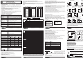
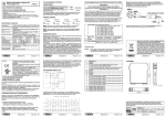
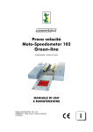
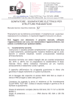
I Z109REG2-H CONVERTITORE UNIVERSALE CON SEPARAZIONE GALVANICA CARATTERISTICHE GENERALI Ingresso universale: tensione, corrente, termocoppie, termoresistenze, potenziometro, reostato. Alimentazione del sensore in tecnica 2 fili: 20 Vcc stabilizzata, 20 mA max protetta dal corto circuito. Misura e ritrasmissione su uscita analogica isolata, con uscita in tensione ed in corrente attiva/passiva. Selezione mediante DIP-switch di: tipo di ingresso, START-END, modo di uscita (elevazione di zero, inversione scala), tipo uscita (mA o V). Indicazione sul frontale di presenza alimentazione, fuori scala o errore di impostazione, stato allarme. Uscita contatto di allarme a relè (spst), impostabile mediante PC. Ingresso di STROBE per attivare l'uscita analogica su comando di un PLC (in alternativa al contatto d'allarme). Possibilità di programmazione mediante PC di inizio e fine scala, tipi di ingresso aggiuntivi, estrazione di radice, filtro, burn-out ecc. Isolamento tra alimentazione e uscita ritrasmessa o ingressi di misura: 3750 Vac. Isolamento tra ingressi di misura e uscita ritrasmessa: 1500 Vac SELEZIONE INGRESSO / SCALA DI MISURA IMPOSTAZIONE START E END DI MISURAA PIACERE La selezione del tipo di ingresso si effettua mediante impostazione del gruppo dipswitch SW1. Ad ogni tipo di ingresso corrisponde un certo numero di valori di inizio scala e di fondo scala selezionabili mediante il gruppo SW2. Nella tabella sottostante vengono elencati i possibili valori di START e END in funzione del tipo di ingresso selezionato; la colonna di sinistra indica la combinazione di dip-switch da impostare per START e END prescelti. I pulsanti START e END posti sotto al gruppo DIP-switch SW2, permettono di impostare l’inizio e il fondo scala a piacere all'interno della scala impostata per mezzo dei dip-switch. Per effettuare questa operazione bisogna disporre di un opportuno generatore di segnale, in grado di fornire il valore di inizio e fine scala desiderati. La procedura da eseguire è la seguente: SW1: TIPO INGRESSO INPUT TYPE Tempo di Risposta: Uscita: Uscita a relè (spst): Condizioni ambientali: Temperatura: -20 - +60°C, Umidità min:30%, max 90% a 40°C non condensante (vedere anche sezione Norme di installazione). Errore Errori riferiti al campo Coeff. Errore di Altro massimo di misura: Calibrazione termico Linearità Ingresso per 0.1% 0.01%/°K 0.05% EMI (4):<1% tensione/corrente: Ingresso per termocoppia 0.1% 0.01%/°K 0.2 °C + (2) J,K,E,T,N: EMI: <1% Ingresso per termocoppia 0.1% 0.01%/°K 0.5 °C + (2) R,S: EMI: <1% Ingresso per termocoppia 0.1% 0.01%/°K 1.5 °C + (2) B (5): EMI: <1% Comp. giunto freddo: 2°C tra 0 e 50°C ambiente. Potenziometro/resistenza: 0.1% 0.01%/°K 0.1% EMI (4):<1% Ingresso termoresistenza 0.1% t > 0°C 0.02% (1) 0.01%/°K (6): t < 0°C 0.05% EMI: <1% Uscita in tensione (3): 0.3% 0.01%/°K 0.01% EEPROM per tutti i dati di configurazione; tempo di ritenuta: Memoria dati 40 anni. Lo strumento è conforme EN61000-6-4 / 2007 (emissione elettromagnetica, alle seguenti normative: ambiente industriale) EN61000-6-2 / 2006 (immunità elettromagnetica, ambiente industriale) EN61010-1/2001 (sicurezza) (1) Influenza della resistenza dei cavi 0.005%/W max 20 W. (2) Influenza della resistenza dei cavi 0.1 mV/W. (3) Valori da sommare agli errori relativi all'ingresso selezionato. (4) EMI: interferenze elettromagnetiche. (5) Uscita zero per t < 400 °C. (6) Tutti gli errori da calcolare sul valore resistivo. Tc K START END 123 456 1 1 W/ Reostato Tc R 2 2 mA Tc S 3 3 NI100 Tc T 4 4 PT100 Tc B 5 5 PT500 Tc E 6 6 PT1000 Tc N 7 7 Tc J Potenziometro 8 8 1 2 3 4 5 6 7 8 DIP-Switch in posizione OFF Tensione Resistenza / Reostato Corrente START (*) 0V 400 mV 1V 2V -5 V -10 V -20 V START (*) 0W 0.5 kW 1 kW 2 kW 5 kW 10 kW 15 kW START (*) 0 mA 1 mA 4 mA -1 mA -5 mA -10 mA -20 mA END (*) 100 mV 200 mV 500 mV 1V 5V 10 V 20 V END (*) 1 kW 2 kW 3 kW 5 kW 10 kW 15 kW 25 kW Potenziometro END (*) 1 mA 2 mA 3 mA 4 mA 5 mA 10 mA 20 mA MI001441-I/E START (*) 0% 10 % 20 % 30 % 40 % 50 % 60 % END (*) 40 % 50 % 60 % 70 % 80 % 90 % 100 % Ora il modulo è configurato per l’inizio e fondo scala richiesti; per riprogrammarlo anche per un tipo diverso di ingresso è sufficiente ripetere l'intera operazione. SELEZIONE USCITA 7 SW2 OUTPUT MODE 0..20mA / 0..10V SW3 1 2 3 4 5 6 7 8 PT100 (RTD) START END (*) (*) -200°C 50°C -100°C 100°C -50°C 200°C 0°C 300°C 50°C 400°C 100°C 500°C 200°C 600°C PT500 (RTD) START END (*) (*) -200 °C 0 °C -100 °C 50 °C -50 °C 100 °C 0 °C 150 °C 50 °C 200 °C 100 °C 300 °C 150 °C 400 °C PT1000 (RTD) START END (*) (*) -200 °C 0 °C -100 °C 50 °C -50 °C 100 °C 0 °C 150 °C 50 °C 200 °C 100 °C 300 °C 200 °C 400 °C 1 2 3 4 5 6 7 8 Termocoppia J START END (*) (*) -200°C 100°C -100°C 200°C 300°C 0°C 100°C 400°C 200°C 500°C 300°C 800°C 500°C 1000°C Termocoppia K START END (*) (*) -200°C 200°C -100°C 400°C 0°C 600°C 100°C 800°C 200°C 1000°C 300°C 1200°C 500°C 1300°C Termocoppia R START END (*) (*) 0°C 400°C 100°C 600°C 200°C 800°C 300°C 1000°C 400°C 1200°C 600°C 1400°C 800°C 1750°C Termocoppia S START END (*) (*) 0°C 400°C 100°C 600°C 200°C 800°C 300°C 1000°C 400°C 1200°C 600°C 1400°C 800°C 1750°C Termocoppia T Termocoppia B Termocoppia E Termocoppia N START END START END START END START END (*) (*) (*) (*) (*) (*) (*) 1 (*) 0°C 500°C -200°C 50°C -200°C 200°C 2 -200°C 50°C -100°C 100°C 500°C 600°C -100°C 100°C -100°C 400°C 3 200°C 0°C 600°C 4 -50°C 150°C 600°C 800°C 0°C 200°C 700°C 1000°C 100°C 300°C 100°C 800°C 5 0°C 250°C 800°C 1200°C 150°C 400°C 200°C 1000°C 6 50°C 7 100°C 300°C 1000°C 1500°C 200°C 600°C 300°C 1200°C 150°C 400°C 1200°C 1800°C 400°C 800°C 500°C 1300°C 8 (*) START o END impostato in memoria mediante PC o pulsanti di programmazione Corrente NORMALE INVERTITA MI001441-I/E MI001441-I/E ITALIANO - 4/8 8 9 12 10 8 9 12 10 12 10 8 9 12 10 P 8 9 12 10 INGRESSO STROBE (7) INGRESSO POTENZIOMETRO/REOSTATO 8 9 12 10 15 + 12..24 Vdc 16 - USCITA RELÈ (10) USCITA RITRASMESSA Tensione 13 Corrente Impressa (8) V output + Corrente Alim. esterna (9) mA output + 13 A 14 A V 14 1 A - 30 V mA output + + 15 16 13 Indicazioni tramite LED sul fronte Significato Lampeggio Fuori Scala, Burn Out o Guasto Interno (freq: 1 lamp./sec) Lampeggio Errore di impostazione dei dip-switch (freq » 2 lamp./sec) Acceso fisso Indica la presenza dell’alimentazione LED Giallo Acceso Significato Segnala Allarme (contatto relè aperto) Spento No Allarme (contatto relè chiuso) ITALIANO - 7/8 IMPOSTAZIONI DA PONTICELLI INTERNI USCITA ATTIVA/PASSIVA J3 J9 Uscita Attiva K1 J2 SW1 Uscita Passiva J9 J9 USCITA RELÈ / INGRESSO STROBE Ingresso STROBE Uscita relè SW3 J3 J2 SW2 J3 J2 NORME DI INSTALLAZIONE Il modulo è progettato per essere montato su guida DIN 46277, in posizione verticale. Per un funzionamento ed una durata ottimale, bisogna assicurare una adeguata ventilazione al/ai moduli, evitando di posizionare canaline o altri oggetti che occludano le feritoie di ventilazione. Evitare il montaggio dei moduli sopra ad apparecchiature che generano calore; è consigliabile il montaggio nella parte bassa del quadro. CONDIZIONI GRAVOSE DI FUNZIONAMENTO: Le condizioni di funzionamento gravose sono le seguenti: Alimentazione del sensore in ingresso. Utilizzo dell'uscita in corrente impressa. Quando i moduli sono montati affiancati è possibile che sia necessario separarli di almeno 5 mm nei seguenti casi: Con temperatura del quadro superiore a 45°C e almeno una delle condizioni di funzionamento gravoso verificata. Con temperatura del quadro superiore a 35°C ed entrambe le condizioni di funzionamento gravose verificate. COLLEGAMENTI ELETTRICI ALIMENTAZIONE La tensione di alimentazione deve essere compresa tra 85 e 265 V sia DC (polarità indifferente) che AC 50-400Hz; vedere anche la sezione NORME DI INSTALLAZIONE. I Iimiti superiori non devono essere superati, pena gravi danni al modulo. E' necessario proteggere la sorgente di alimentazione da eventuali guasti del modulo mediante fusibile opportunamente dimensionato. MI001441-I/E MI001441-I/E POSIZIONE PONTICELLI INTERNI Le istruzioni per l'impostazione ed il cavetto di collegamento sono forniti a corredo del software che deve essere richiesto come accessorio. 3 mV/TC input ITALIANO - 5/8 Per mezzo di un PC e del software ZSETUP2 è possibile impostare oltre a fine e inizio scala, altri parametri normalmente fissi: Tipi di ingresso aggiuntivi; Filtro digitale (normalmente escluso); Estrazione di radice (normalmente escluso); Burn-out negativo (normalmente positivo); Allarme (normalmente impostato come segnalazione errore); Inizio e fine scala dell’uscita analogica; Valore dell’uscita analogica in caso di errore; Reiezione a frequenza di rete 50/60 Hz (normalmente impostata a 50 Hz); Velocità di campionamento/risoluzione (normalmente impostata a 15 sps/16 bit); Misura a 3 o 4 fili per termoresistenze (normalmente impostata a 3 fili); Azione del relè d’allarme in caso di fault dello strumento; 85 - 265 V DC/ AC 50 - 400Hz 2,5 W Max 10 In alternativa all’uscita a relè. È isolato dai rimanenti circuiti e serve ad abilitare l’uscita analogica in corrente. Può essere utilizzato per multiplexing di un ingresso di PLC su n Z109REG2-H. Per abilitare vedi IMPOSTAZIONI DA PONTICELLI (8) Uscita attiva già alimentata da collegare a ingressi passivi. (9) Uscita passiva non alimentata da collegare a ingressi attivi. Per selezionare vedi IMPOSTAZIONI DA PONTICELLI INTERNI. (10) Abilitata in alternativa all’ingresso STROBE; contatto relè normalmente chiuso, aperto in caso di allarme. Tensione 4..20mA / 2..10V 1 11 L'alimentazione del loop è data dal modulo INGRESSO TERMORESISTENZA PT100, NI100, PT500, PT1000 NTC, KTY81, KTY84 RTD 4 fili RTD 3 fili RTD 2 fili INGRESSO TERMOCOPPIA R 9 + (7) 12 8 LED Verde 10 + V input > 300 mV 7 + L'alimentazione del loop è data dal sensore 14 USCITA IMPOSTAZIONE MEDIANTE PC NI100 (RTD) START END (*) (*) -50 °C 20 °C -30 °C 40 °C -20 °C 50 °C 80 °C 0 °C 20 °C 100°C 30 °C 150 °C 50 °C 200 °C 11 + INGRESSO IN TENSIONE mA input (2 fili) mA input Con resistenza R=500 W (non fornita), P= 500 W ¸ 100 kW N.B.: l'impostazione dei dip-switch deve avvenire a modulo non alimentato, evitando scariche elettrostatiche, pena il possibile danneggiamento del modulo stesso. ITALIANO - 3/8 N.B.: l'impostazione dei dip-switch deve avvenire a modulo non alimentato, evitando scariche elettrostatiche, pena il possibile danneggiamento del modulo stesso. ITALIANO - 2/8 1. Impostare tramite il corrispondente gruppo di dip-switch il tipo di ingresso desiderato, START e END di misura che comprendano l’inizio e il fondo scala di misura desiderati. 2. Fornire alimentazione al modulo. 3. Predisporre un generatore o un calibratore del segnale che si intende misurare e ritrasmettere. 4. Impostare sul generatore il valore di inizio scala desiderato. 5. Premere il pulsante START per almeno 3 sec. Un lampo del led verde sul frontale dello strumento indica l'avvenuta memorizzazione del valore. 6. Ripetere i punti 4 e 5 per il valore di END desiderato. 7. Togliere alimentazione al modulo e porre in posizione OFF i dip-switch del gruppo SW2 relativi all’impostazione dei valori di START e END. I DIP-switch numero 7 ed 8 del gruppo SW2 permettono di impostare rispettivamente l'uscita con o senza elevazione di zero, uscita normale o invertita. Il gruppo DIP-switch SW3 permette di selezionare il tipo d'uscita. 1 23 456 78 SW2 ITALIANO - 1/8 35 ms con risoluzione 11 bit, 140 ms con risoluzione 16 bit (misure di tensione, corrente, potenziometro). Corrente impressa 0..20 / 4..20 mA, max resistenza di carico 600 W Tensione 0..5 V / 0..10 V / 1..5 V / 2..10 V, min resistenza di carico 2 kW Risoluzione 2.5 mA / 1.25 mV. Portata: 1 A - 30 Vdc/Vac MI001441-I/E 1234 V Alimentazione: MI001441-I/E INPUT TYPE 1234 SPECIFICHE TECNICHE 85-265 Vdc o Vac 50-400 Hz, max 2.5 W; 1.6 W @ 220 Vac con output 20 mA. Bipolare da 75 mV fino a 20 V in 9 scale, impedenza di Ingresso tensione: ingresso 1 MW, risoluzione max 15 bit + segno. Ingresso corrente: Bipolare fino a 20 mA, impedenza di ingresso ~50 W, risoluzione max 1 mA Ingresso termoresistenza Misura a due, tre o quattro fili, corrente di eccitazione 0.56 (RTD) PT100, PT500, mA, risoluzione 0.1 °C, rilevamento automatico interruzione PT1000, NI100, KTY81, cavi o RTD. Per NTC valore resistivo < 25 kW. KTY84, NTC. KTY81, KTY84 e NTC impostabili solo via software. Ingresso termocoppia: Tipo J, K, R, S, T, B, E, N; risoluzione 2.5 mV, rilevamento automatico interruzione TC, impedenza di ingresso >5 MW Ingresso reostato: Fondo scala min 500 W, max 25 kW. Ingresso potenziometro: Tensione di eccitazione 300 mV, impedenza di ingresso > 5 MW, valore potenziometro da 500 W a 10 kW (con l'ausilio di un resistore in parallelo pari a 500 W ). Variabile da 240 sps con risoluzione 11 bit + segno a 15 sps Frequenza di con risoluzione 15 bit + segno (valori tipici). Campionamento: SW2 : START e END INGRESSO IN CORRENTE ITALIANO - 6/8 COLLEGAMENTI ELETTRICI Si raccomanda l'uso di cavi schermati per il collegamento dei segnali per soddisfare i requisiti di immunità; lo schermo dovrà essere collegato ad una terra preferenziale per la strumentazione. Inoltre è buona norma evitare di far passare i conduttori nelle vicinanze di cavi di installazioni di potenza quali inverter, motori, forni ad induzione ecc. Questo documento è di proprietà SENECA srl. La duplicazione e la riproduzione sono vietate, se non autorizzate. Il contenuto della presente documentazione corrisponde ai prodotti e alle tecnologie descritte. I dati riportati potranno essere modificati o integrati per esigenze tecniche e/o commerciali. Il contenuto della presente documentazione viene comunque R THE INTERNATIONAL CERTIFICATION NETWORK ISO9001-2000 SENECA s.r.l. Via Germania, 34 - 35127 - Z.I. CAMIN - PADOVA - ITALY Tel. +39.049.8705355 - 8705359 - Fax +39.049.8706287 e-mail: [email protected] - www.seneca.it MI001441-I/E ITALIANO - 8/8 EN SELECTION: INPUT / MEASURING SCALE SETTING START AND END AT WILL The type of input is selected by setting the SW1 dip-switch group at the side of the module. Every type of input is matched to a certain number of scale beginnings and ends values which can be selected with the SW2 group. The table below lists possible START and END values according to the type of input selected. The START and END push-buttons under the SW2 DIP-switch group allow to set the beginning and end scale at will within the scale pre-set through the dip-switches. To obtain this facility it is necessary to use a suitable signal generator, able to furnish the desidered values of beginning and end scale. The procedure is following: GENERAL CHARACTERISTICS Universal input: voltage, current, thermocouples, thermoresistences, potentiometer, rheostat. Sensor powered by 2-wire technique: 20 Vcc stabilised, 20mA max with shortcircuit protection. Measurement and re-transmission on isolated analog output, with voltage and current output . DIP-switch for selecting: type of input, START-END, output mode (zero elevation, scale inversion), output voltage type (mA or V ). Front panel indicating: power on, off scale or setting error, alarm status. Relay (spst) output, programmable through PC. STROBE input to activate the analog output on PLC command (alternatively to alarm contact). Facility for programming the following with a PC: beginning and end scale, additional input types, square root extraction, filter, burn-out etc. Insulation between supply and output or input: 3750 Vac. Insulation between output and input: 1500 Vac. SW1: INPUT TYPE INPUT TYPE 1234 Voltage input: 2 3 3 NI100 Tc T 4 4 PT100 Tc B 5 5 PT500 Tc E 6 6 PT1000 Tc N 7 7 Tc J Potentiometer 8 8 1 23 456 78 1 2 3 4 5 6 7 8 Excitation voltage 300 mV, input impedance > 5 MW, potentiometer value from 500 W to 10 kW (with the aid of a parallel resistence equal to 500 W). Variable from 240 sps with 11 bits resolution + sign to 15 sps with 15 bits + sign resolution (typical values). Sampling frequency: MI001441-I/E Response Time: Output: Relay output (spst) : Errors referred to max measuring range: Input for voltage/current: Input for thermocouple J,K,E,T,N: Input for thermocouple R,S: Input for thermocouple B (5): Temperature: -20 - +60°C, Humidity min: 30%, max: 90% a 40°C non condensing (also see section Installation instructions). Calibration Thermal Linearity Others Error Coefficie error 0.1% 0.01%/°K 0.05% EMI(4): <1% 0.1% 0.01%/°K 0.2 °C + (2) EMI: <1% 0.1% 0.01%/°K 0.5 °C + (2) EMI: <1% 0.1% 0.01%/°K 1.5 °C + (2) EMI: <1% Cold junction compens.: Potentiometer/resistor : 2°C in ambient range 0 to 50°C. 0.1% 0.01%/°K 0.1% Environmental conditions: Input for thermoresistance (6): Voltage output (3): 0.1% 0.01%/°K 0.3% 0.01%/°K EMI (4):<1% t > 0°C 0.02% (1) t < 0°C 0.05% EMI: <1% 0.01% Data Memory EEPROM for all configuration data; storage time: 40 years. Standards EN61000-6-4 / 2007 (electromagnetic emission, industrial environment) EN61000-6-2 / 2006 (electromagnetic immunity, industrial environment) EN61010-1/2001 (safety) (1) Influence of cable resistance 0.005%/W max 20 W. (2) Influence of cable resistance 0.1 mV/W. (3) Values to be added to the errors of the selected input. (4) EMI: electromagnetic interferences. (5) Output zero if t < 400 °C. (6) All the values have to be calculated on the resistive value. MI001441-I/E DIP-Switch to OFF position Voltage START (*) 0V 400 mV 1V 2V -5 V -10 V -20 V END (*) 100 mV 200 mV 500 mV 1V 5V 10 V 20 V ENGLISH - 1/8 35 ms with 11 bits resolution, 140 ms with 16 bits resolution (measurement of voltage, current, potentiometer). Generated Current 0..20 / 4..20 mA, max load resistance 600 W Voltage 0..5 V / 0..10 V / 1..5 V / 2..10 V, min load resistance 2 kW Resolution: 2.5 mA / 1.25 mV. Capacity : 1 A - 30 Vdc/Vac 1 2 Thermocouple input: Full scale min 500 W, max 25 kW. 456 1 Tc S SW2 Potentiometer input: 123 mA Bipolar up to 20 mA, input impedance ~50 W, resolution: 1mA. Thermoresistance (RTD) 2, 3 or 4 wires measurement, energising current 0.56 mA, input PT100, PT500, resolution 0.1 °C, automatic detection of cable interruption PT1000, NI100, KTY81, or RTD. Resistive value for NTC: < 25 kW. KTY84 and NTC. KTY81, KTY84 an NTC may be set only via software. Rheostat input: END W/ Rheostat Bipolar from 75 mV up to 20 V in 9 scales, input impedance 1 MW, resolution max 15 bit + sign. Type J,K,R,S,T,B,E,N; resolution: 2.5 mV, automatic detection of TC interruption, input impedance >5 MW Tc K START Tc R 85-265 Vdc or Vac 50-400 Hz, max 2.5 W; 1.6W @ 220Vac with 20mA output. Current input: 1234 V TECHNICAL SPECIFICATIONS Power supply: SW2 : START and END INPUT TYPE Resistance / Rheostat Current START (*) 0W 0.5 kW 1 kW 2 kW 5 kW 10 kW 15 kW START (*) 0 mA 1 mA 4 mA -1 mA -5 mA -10 mA -20 mA END (*) 1 kW 2 kW 3 kW 5 kW 10 kW 15 kW 25 kW Potentiometer END (*) 1 mA 2 mA 3 mA 4 mA 5 mA 10 mA 20 mA MI001441-I/E START (*) 0% 10 % 20 % 30 % 40 % 50 % 60 % END (*) 40 % 50 % 60 % 70 % 80 % 90 % 100 % ENGLISH - 2/8 + 11 N.B.: DIP-switches must be set while the module is powered down, avoiding electrostatic discharges, otherwise the module may be damaged. SW2 OUTPUT MODE 0..20mA / 0..10V SW3 10 P Current 8 NORMAL REVERSED MI001441-I/E 1 2 3 4 5 6 7 8 By using a PC and ZSETUP2 software, it is possible to set other normally fixed parameters in addition to start and end scale: Additional input types.Digital filter (normally disabled); Square root extraction (normally disabled); Negative burn-out (normally positive); Alarm(normally set as error signalling; Start and end scale of the analog output; Value of the analog output in case of error; Rejection programmable for 50 or 60 Hz mains frequency (normally set to 50 Hz); Sampling frequency/resolution (normally set to 15 sps/16 bit); 3 or 4 wires measure for thermal resistance (normally set to 3 wires); Action of the digital output alarm in case of fault; Thermocouple J START END (*) (*) -200°C 100°C -100°C 200°C 0°C 300°C 100°C 400°C 200°C 500°C 300°C 800°C 500°C 1000°C Thermocouple K START END (*) (*) -200°C 200°C -100°C 400°C 0°C 600°C 100°C 800°C 200°C 1000°C 300°C 1200°C 500°C 1300°C Thermocouple R START END (*) (*) 0°C 400°C 100°C 600°C 200°C 800°C 300°C 1000°C 400°C 1200°C 600°C 1400°C 800°C 1750°C Thermocouple S START END (*) (*) 0°C 400°C 100°C 600°C 200°C 800°C 300°C 1000°C 400°C 1200°C 600°C 1400°C 800°C 1750°C Instructions for setting and for the connection cable are supplied with the software (to be requested as an accessory item). 1 2 3 4 5 6 7 8 Thermocouple T START END (*) (*) -200°C 50°C -100°C 100°C -50°C 150°C 0°C 200°C 50°C 250°C 100°C 300°C 150°C 400°C Thermocouple B START END (*) (*) 0°C 500°C 500°C 600°C 600°C 800°C 700°C 1000°C 800°C 1200°C 1000°C 1500°C 1200°C 1800°C Thermocouple E START END (*) (*) -200°C 50°C -100°C 100°C 0°C 200°C 100°C 300°C 150°C 400°C 200°C 600°C 400°C 800°C Thermocouple N START END (*) (*) -200°C 200°C -100°C 400°C 0°C 600°C 100°C 800°C 200°C 1000°C 300°C 1200°C 500°C 1300°C LED Indication on the front Meaning Flashing Out Range, Burn Out or Internal fault (freq: 1 Flash./sec) Flashing Error on dip-switches setting (freq » 2 Flash./sec) Indicates the presence of power supply Yellow LED Steady ON Meaning Alarm Signalling (relay contact opened) OFF No Alarm (relay contact closed) 3 V output + mA output + 13 Power supply voltage must be in the range 85 to 265V either DC (at any polarity) or AC 50-400Hz; also see section INSTALLATION INSTRUCTIONS. The upper limits must not be exceeded, to avoid serious damage to the module. Protect the power supply source against possible damage of the module by using a fuse of suitable size. MI001441-I/E RELAY OUTPUT (10) External Power Supply Current (9) A 14 A 14 1 A - 30 V mA output + + 15 16 13 MI001441-I/E ENGLISH - 7/8 SETTINGS THROUGH INTERNAL BRIDGES ACTIVE / PASSIVE Active Output J3 J9 K1 J2 SW1 Passive Output J9 J9 RELAY OUTPUT / STROBE INPUT STROBE INPUT Relay Output SW3 J3 J2 SW2 J3 J2 INSTALLATION INSTRUCTIONS The module was designed for fitting to guide DIN 46277, in a vertical position. For optimum operation and long life, make sure adequate ventilation is provided for the module/s, avoiding placing raceways or other objects which could obstruct the ventilation grilles. Do not install the modules above appliances generating heat we advise you to install in the lower part of the panel. ELECTRICAL CONNECTIONS We advise you to use shielded cables for connecting signals. The shield must be connected to an earth wire used specifically for instrumentation. Moreover, it is good practice to avoid routing conductors near power appliances such as inverters, motors, induction ovens, etc. ELECTRICAL CONNECTIONS 85 - 265 V DC/ AC 50 - 400Hz 2,5 W Max 13 Generated Current (8) SEVERE OPERATING CONDITIONS: Severe operating conditions are as follows: Power supply of the sensor at input. Use of the output on generated current. When modules are installed side by side, it may be necessary to separate them by at least 5 mm in the following cases: If panel temperature exceeds 45°C and at least one of the severe operating conditions exists. If panel temperature exceeds 35°C and both the severe operating conditions exist. POWER SUPPLY 1 16 - RE-TRANSMITTED OUTPUT Voltage INTERNAL BRIDGES POSITION SETTING WITH A PC Steady ON 15 + 12..24 Vdc With resistance R=500 W (not provided), P= 500 W ¸ 100 kW ENGLISH - 5/8 PT1000 (RTD) START END (*) (*) -200 °C 0 °C -100 °C 50 °C -50 °C 100 °C 0 °C 150 °C 50 °C 200 °C 100 °C 300 °C 200 °C 400 °C Green LED 8 9 12 10 (7) As alternative to the relay output. It is isolated from the other circuits and enables the current analog output. It may be used to multiplex a PLC input on n Z109REG2-H. To enable it see SETTINGS THROUGH INTERNAL BRIDGES. (8) Active Output (powered) to connect to passive inputs. (9) Unpowered passive output to be connected to active inputs. To enable it, see SETTINGS THROUGH INTERNAL BRIDGES. (10) As alternative to STROBE input; relay contact normally closed, opened in event of alarm. Voltage 4..20mA / 2..10V 8 9 12 10 STROBE INPUT (7) 8 9 12 10 14 12 8 9 12 10 8 9 12 10 V OUTPUT 10 The loop is powered by the module 12 SELECTING OUTPUT DIP-switches numbers 7 and 8 of the SW2 group enable you to set the output with or without zero elevation, or as a normal or reversed output. The SW3 DIP-switch group enables you to select the output type. 9 + THERMORESISTANCE INPUT THERMOCOUPLE INPUT PT100, NI100, PT500, PT1000 NTC, KTY81, KTY84 RTD 4 wires RTD 3 wires RTD 2 wires R PT500 (RTD) START END (*) (*) -200 °C 0 °C -100 °C 50 °C -50 °C 100 °C 0 °C 150 °C 50 °C 200 °C 100 °C 300 °C 150 °C 400 °C ENGLISH - 4/8 10 The loop is powered by the sensor POTENTIOMETER/RHEOSTAT INPUT PT100 (RTD) START END (*) (*) -200°C 50°C -100°C 100°C -50°C 200°C 0°C 300°C 50°C 400°C 100°C 500°C 200°C 600°C MI001441-I/E 7 + The module is now configured for the required start and end scale. To re-program it (e.g. for a different type of input) repeat the whole procedure. NI100 (RTD) START END (*) (*) -50 °C 20 °C -30 °C 40 °C -20 °C 50 °C 0 °C 80 °C 20 °C 100°C 30 °C 150 °C 50 °C 200 °C N.B.: DIP-switches must be set while the module is powered down, otherwise, the module may be damaged. 11 + mV/TC input ENGLISH - 3/8 1 2 3 4 5 6 7 8 (*) START or END are set in the memory with the PC or with the programming pushbuttons mA input (2 wires) mA input 1. Set through dip-switches the type of input, START and END measurement which include the required beginning and end values. 2. Power up the module. 3. Supply a calibrator or simulator of the signal you wish to measure and re-transmit. 4. Set the required START value on the calibrator (or other instrument). 5. Press the START push-button for at least 3 sec. The green LED on the front panel flashes to indicate the value has been stored. 6. Repeat points 4 and 5 for the required END value. 7. Cut power to the module and set to OFF position the dip-switches of group SW2, correspondent to the settings of START and END values. 7 VOLTAGE INPUT V input > 300 mV CURRENT INPUT Z109REG2-H UNIVERSAL CONVERTER WITH GALVANIC SEPARATION ENGLISH - 6/8 This document is property of SENECA srl. Duplication and reprodution are forbidden, if not authorized. Contents of the present documentation refers to products and technologies described in it. All technical data contained in the document may be modified without prior notice Content of this documentation is subject to periodical revision. R THE INTERNATIONAL CERTIFICATION NETWORK ISO9001-2000 SENECA s.r.l. Via Germania, 34 - 35127 - Z.I. CAMIN - PADOVA - ITALY Tel. +39.049.8705355 - 8705359 - Fax +39.049.8706287 e-mail: [email protected] - www.seneca.it MI001441-I/E ENGLISH - 8/8