1
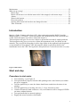
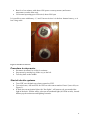
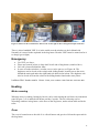
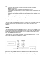
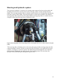
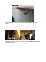
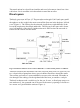
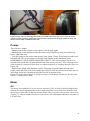
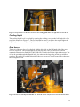
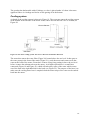
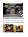
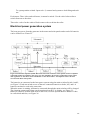
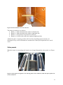
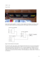
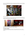
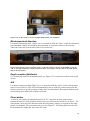
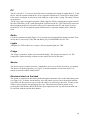
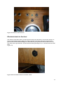
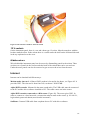
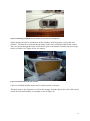
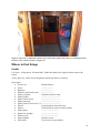
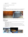
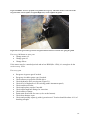
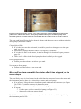
User manual for Maja a 30 foot Fisher motor sailer J. Havskov June 2014 1 Introduction ................................................................................................................................ 3 Start and stop .............................................................................................................................. 3 Procedure to start motor ......................................................................................................... 3 Procedure to stop motor ......................................................................................................... 4 Start of electric systems .......................................................................................................... 4 While running ......................................................................................................................... 5 VHF ............................................................................................................................................ 5 Emergency .................................................................................................................................. 6 Heating ....................................................................................................................................... 6 Motor running ........................................................................................................................ 6 Oven ....................................................................................................................................... 6 Water .......................................................................................................................................... 7 Gas .............................................................................................................................................. 8 Steering and hydraulic system.................................................................................................. 10 Auto pilot.................................................................................................................................. 12 Diesel system............................................................................................................................ 13 Pumps ....................................................................................................................................... 14 Motor ........................................................................................................................................ 14 Oil ......................................................................................................................................... 14 Cooling liquid ....................................................................................................................... 15 Gear box oil .......................................................................................................................... 15 Cooling system ..................................................................................................................... 16 Toilet ........................................................................................................................................ 18 Electrical power generation system .......................................................................................... 20 Solar panels .......................................................................................................................... 21 Charging and discharging batteries ...................................................................................... 24 Monitoring voltage and current ............................................................................................ 24 Electrical units and fuses .......................................................................................................... 24 Converter to 220 V ............................................................................................................... 25 Wind speed and direction ..................................................................................................... 26 Depth sounder (fishfinder) ................................................................................................... 26 AIS ....................................................................................................................................... 26 Chart plotter.......................................................................................................................... 26 Radar .................................................................................................................................... 27 PC ......................................................................................................................................... 28 Radio .................................................................................................................................... 28 Lights .................................................................................................................................... 28 Fridge ................................................................................................................................... 28 Navtex .................................................................................................................................. 28 Electrical winch at the back.................................................................................................. 28 Electrical winch in the front ................................................................................................. 29 12 V sockets ......................................................................................................................... 30 Hidden wirers ....................................................................................................................... 30 Internet ..................................................................................................................................... 30 Tables, benches, chart table etc ................................................................................................ 31 Heavy weather .......................................................................................................................... 32 Where to find things ................................................................................................................. 34 Inside .................................................................................................................................... 34 Outside ................................................................................................................................. 35 2 Maintenance ............................................................................................................................. 35 What can go wrong ? ................................................................................................................ 37 Motor stops ........................................................................................................................... 37 Motor will not turn over with the starter after it has stopped, or the motor stops ................ 38 Alarms .................................................................................................................................. 39 Water in the bottom .............................................................................................................. 40 Electrical problem ................................................................................................................ 40 Steering wheel turns but boat does not change direction ..................................................... 40 Tiller is blocked .................................................................................................................... 41 Introduction Maja is a Fisher 30 motor sailer from 1978. It has registration number RAD122 and the MMSI number is 257564850. It has hull number 158, molded into the side of the boat and visible inside the anchor rope locker at the back (Figure 1). This description will give an overview of how to operate the boat and fix simple problems. This description only gives an overview of how the instruments work, for details see the manuals. They are placed all together in a blue large folder in the cupboard in the dog house, except manuals for chart plotter, VHF and autopilot which are placed on shelf for the instruments next to the VHF. The log book is also placed here. It must be used for every trip. Figure 1 Hull number Start and stop Procedure to start motor Turn on battery 1 (see Figure 2). Turn gas handle 45 degrees forward while pushing in the center button (to avid that the gear is engaged). Turn the ignition key to start, the alarms should now sound since the motor is not running. Turn the ignition key to heating, leave for 5- 10 sec, then turn to start. Connect all batteries (both switches to ‘all’) so all batteries will be charged, NEVER run motor without batteries. Turn gas handle back to neutral (right up). Engage the motor forwards or backwards. 3 Run for a few minutes with about 1500 rpm to warm up motor (until motor temperature reaches blue area). Use normal operating speed if desired, about 2200 rpm It is possible to start with battery 1, 2 and 3 but not 4 since it is the bow thruster battery, so it has a long cable. Figure 2 Switches for batteries Procedure to stop motor Put motor in neutral, let it idle for a minute. Stop motor by turning key all the way to the left. Turn key back to the middle. Start of electric systems Turn VHF on with knob on volume control on VHF. Turn wind vane, AIS and GPS for VHF on with contact marked ‘Instr’ (lower left, see Figure 3). If dark, turn on navigation light with ‘Nav lights’, will turn on red, green and white light in the back. If under motor, also turn on masthead light (M. Head switch), located halfway up the main mast and lighting forwards. 4 Figure 3 Left part of instrument panel. Left round switch is for heating. ComNav is the auto pilot. Above the log is seen the dimmer for the compass light. The windlass is for the front winch. While running Have a look at the instrument panel periodically to check that all measures (oil pressure (around 6), motor temperature (80-90) and voltage (13.2) are within acceptable ranges. Check that cooling water comes out of the exhaust pipe (back, left side). Check that cooling water comes out of the cooling water air vent (small outlet at the back on right hand side). VHF The VHF (Figure 4) normally operates on channel 16, the distress and call channel. The call sign of the radio is LL 9795 and the MMSI number is 257564850. For call to a coast radio, a working channel must be used, see list above radio. Select channel, either by turning channel wheel or using button on microphone. Transmit to coast radio by pressing button on microphone. E.g. “Rogaland radio, this is Maja, Lima Lima 9795 on channel 25”. Wait for response from coastal radio, It is also possible to call using SelCall, a digital service, see VHF manual. When “Instr” is turned on, (should normally be on), the VHF receives the position, speed and heading from an independent GPS (white box on roof outside, above VHF). This information is displayed on the VHF screen, see Figure 4 . When the distress button is pressed, the name and number of Maja as well as the position is set on an emergency channel to other boats with SelCall as well as the cost radio. If the coast radio has received the signal, it will call back. 5 Figure 4 VHF. Note the red button for distress call. To the right is shown navigation output from GPS. There is also a handheld VHF. It is in the cradle near the window on the left hand side. Normally it is stored in the cupboard in the dog house. Breaker VHF2 must be turned on for it to charge (green light). Emergency Use VHF, see above. Flares are located below on large shelf in left side of dog house (round red box). Life raft is located behind the mast. In case of broken windows, wooden covers can be put on, see Figure 46. The doghouse can be closed to the cockpit with sliding boards, located next to the stairs, behind the stairs and under the right hand side bunk in the saloon. The doghouse can also be closed off from the saloon with sliding boards found at the same places. IsatPhone PRO: Number 00870 776 40 73 69, sim number: 898 709 910 416 140 969 Heating Motor running When the more is running, heating by hot air can be used starting the air blower on instrument panel (Figure 3). It is marked with heater and has 3 speeds. The air is blowing out for defrosting windows in dog house, at the floor of the dog house, under saloon table and in the toilet. Oven The oven is located next to the sink. It is a diesel burner and gets its oil from the spare tank in the dog house. 6 Start Stop Turn on the main diesel line, crane just behind the oven on the oil regulator. Remove lid from oven. Pour in a ‘drink’ ethanol (found in lowest cupboard next to oven). Turn on heater with rotary switch on oven oil regulator, regulator at lowest level (just after start). Light with a match and replace lid. In unfavorable wind conditions, the fire goes out quickly, try again. It can be seen if the fire is on looking through the small hole in the cover. If it starts burning ok, the heating can increase after a few minutes. Do not use the maximum setting, the oven might be red hot. Turn off on the rotary regulator and the main oil crane. The oven can often not be used under sail since the sail might press air down the chimney and the smoke comes out in the cabin. This can also happen without sail in special wind conditions. Water The cold water tank is located under the bunk in front. It is filled by a filler cap on the deck in the front. Follow the level while filling on the level tube located near the front cabin. Do not fill above the top mark since water then might overflow through the air tube into the front bunk. The tank holds approximately 100 l. The hot water tank is located in the motor room, left side. It holds approximately 20 l. It is heated by the motor and keeps warm for about 24 hours. Figure 5 Fresh water system. The valve shown for toilet and kitchen can either be in warm or cold position and no mixing can be done. The valve for hot and cold water in the kitchen is located above the oven, see Figure 6. 7 Figure 6 Location of valve for hot and cold water. The handle is in the warm position. Gas The most likely, cause of explosion on board is a leaking gas system. The gas is heavier than air and will sink to the bottom of the boat so it can also kill you. So be careful. The gas bottles are located in the gas locker just outside the doghouse, on the left. It is drained to the outside of the boat so if a bottle starts leaking the gas should drain outside the boat. If gas leaks into the main cabin, a gas detector will give an alarm. The detector is located under the stairs, is always on (green light) if the electricity is turn on, SO DO NOT TURN OFF ELECTRICITY WHEN SLEEPING. The gas system can be checked for leakage: Open gas bottle crane. Push the button on leak detector up, if any gas is leaking out of the system, bubbles will be seen (see Figure 8). Test leak detector by turning on the gas stove, bubbles should be seen. There is room for 2 bottles (standard 5 kg) but only one is connected. The schematics of the gas system is shown in Figure 7. Figure 7 Schematics of the gas system 8 Figure 8 Gas room. In upper left hand corner is seen the leak detector. Operation Turn on gas in gas locker, crane on top of gas bottle. Close gas locker. Turn on gas in the locker under the bunk (see Figure 9) Turn gas handle for a burner, hold it in and light it with the red push button. Hold switch for a couple of seconds, if the gas blows out, the gas supply should be switch off to that burner. When not using the stove, turn off crane near stove. When sleeping or leaving the boat, turn of main crane in gas locker. Figure 9 Gas switch just before the stove. The rubber tube goes to the stove. The figure shows the switch off position. 9 Steering and hydraulic system The steering is hydraulic. It consists of a steering pump connected to the steering wheel and hydraulic hoses from the steering wheel to the steering cylinder, which actually turns the rudder. The steering pump has valves to that the wheel remains in a fixed position and thereby locks the position of the rudder. The autopilot pump is connected in parallel to the manual steering pump. Between the auto pilot pump and the steering pump, there is a rubber hose for airing the system and allowing return of hydraulic fluid. Figure 10 Steering pump, seen from opening in saloon. The middle hose is for overflow from the auto pilot pump. Tiller steering: Due to blocking valve in the auto pilot pump and the steering pump, the tiller cannot normally be moved. In order to move the tiller, the bypass valve under the seat in the cockpit (see Figure 11) must be opened. The fluid then passes through this valve when the tiller is moved. Neither the auto pilot nor the wheel steering can now be used since the hydraulic fluid would then pass through the bypass valve. 10 Figure 11 The handle of the bypass valve to change from tiller steering (rudder) to wheel steering (normal). Maintenance: Once the system has been properly aired (see manufactures description) there should be no maintenance needed. It is possible that a bit of fluid must be added in case of a small leakage or because there is still some air in the system which has escaped. To check the fluid level, see the level in the reservoir (see Figure 12 and Figure 32). It should be about half full, if not add hydraulic fluid (found with oil in motor room). Figure 12 Left: Steering wheel and hose to the hydraulic oil reservoir. Right: Reservoir for hydraulic oil, brown bottle with white cap. 11 Figure 13 Schematics of hydraulic system. Auto pilot The auto pilot can either steer the boat at a given course or it can steer to a waypoint defined by the chart plotter. The control unit is located to the left on the instrument panel, see Figure 14. Figure 14 Autopilot control unit. To operate Steer boat in wanted direction: Press ‘Pilot’ and the boat will continue in same direction. Change course by 1 degree left or right by pressing red and green button, respectively Change course by a larger amount: Hold down green or red key until direction is correct, then press Pilot? Turn off by pressing ‘Off’. 12 The control unit can be released from its holder and moved a few meters since is has a loose cable below. So it is possible to sit in the cockpit to control the auto pilot. Diesel system The diesel system seen in Figure 15. The system has a main tank of 160 l and a spare tank of about 18 l. Both tanks are made of wood covered by epoxy. The main tank is located between the doghouse and the cockpit in the motor room and the spare tank in the doghouse, left-back corner (Figure 16). The filler cap for the main tank is located on the right hand side of the boat on the step between the cockpit and the side. The filler cap for the spare tank is located on the left hand side of the cockpit. Only the main tank is filled up since the spare tank is filled up by the overflow from the motor. Figure 15 Schematics of diesel system. Cranes are indicted by T’s. Their normal positions are indicated. The diesel flows from the main tank to first filter (located in motor room, see Figure 20), then to the electrical diesel pump form where it goes to the fine filter before entering the motor. The overflow goes back to the spare tank which overflows to the main tank. Both tanks are aired through a tube ending up on the right hand side if the boat, just outside the cockpit. The diesel in the spare tank is used directly for the oven. In case, the diesel pump stops or the main tank runs dry, the spare tank can also be used for the motor by opening the closed valve in the motor room (just behind the stairs, see Figure 16). 13 Figure 16 Left: Valve for diverting oil from the spare tank to the motor. The valve is show in closed position (normal operation). Right: Spare diesel tank in cockpit. Notice the glass window showing the diesel level, normally it should be almost full. Pumps The boat has 5 pumps: - Manual pump in the cockpit (water empties over the back right). - Manual pump in the doghouse under the bench (water empties on deck just outside dog house, right hand side). - 2 electric pumps in the motor room (pump1 back, pump 2 front). Water empties at the back, left hand side. The electric pumps are started with buttons on the instrument panel. REMEMBER TO STOP WHEN FINISHED USING IT. The electric pumps also have an internal float switch and will start automatically if the water level rises. This will happen also if the electricity is turned off since they are connected directly to a battery through a fuse (see Figure 34). - Small electric pump with automatic switch. This pump is placed higher than the other pumps, under the floor in the locker under the cockpit. It will only be activated if the water is quite high. It also has a manual switch placed in the aft outside locker. Punmp1 is connected to battery 2, pump 2 to battery 3 and pump3 to battery 4. So that lease battery 1 without power drain. Motor Oil The motor uses synthetic oil, it can also use normal oil. The oil level is checked with the dip stick on the motor right hand side (remove right hand floor cover). The level should be near the top level. Spare oil is in the box near the motor. The oil is put in on top of the valve cover (Figure 17), remove middle floor cover to get access. Oil consumption should be less than 0.5 l in 200 hours. 14 Figure 17 Top of motor: To the left is seen cover for cooling liquid and to the right the cover for the oil. Cooling liquid The cooling liquid level is checked by opening the cooling cover, on the left hand side of the top of the motor, see Figure 17. The level should be about 3 cm below the top, if higher the liquid is just thrown out. Spare liquid is in the box to the right of the motor. Gear box oil The level of the gear box oil is checked with the dip stick on the left hand side of the gear box, see Figure 18. The level should be near the top mark. The gear box uses Dextron automatic transmission fluid (NOT MOTOR OIL) found in box to the right of the motor. The oil can be put in through the dipstick hole, else unscrew the large plug on the top middle of gear box. Be careful to push the dipstick all the way down so it is well seated since otherwise the oil might leak out. Figure 18 Gear box with dip stick and filler cap. Near the square relay boxes are two fuses for the motor. 15 The gearbox has had trouble with oil leakage so a box is placed under it. It then it becomes apparent if there is a leakage and it also avoids getting oil in the bottom. Cooling system A sketch of the cooling system is shown in Figure 19. The sea water enters the cooling system in the bottom in the left side of the motor room, where also the shut off valve is located, see Figure 20. Figure 19 The motor cooling system. The arrows show the normal flow direction. The water then enters the water filter (Figure 20) located above the sea level. It then goes to the water pump in the front of the motor (Figure 21), cools the motor and comes out as hot water at the back of the motor. From there it enters a long loop putting it above the sea level before it enters the exhaust tube near the motor. At it highest point there is a small hose connected (Figure 19 and Figure 51) which will take away some of the water which comes out of the boat at the right hand side in the back (see Figure 52). The purpose of the hose is to make sure the cooling water hose is emptied when the motor stops so no water can be sucked back into the motor. 16 Figure 20 Bottom left of motor room. Top left shows the diesel filter, bottom left the water lock and silencer, top right the water filter, in the middle right the inlet water valve (red handle) and to the right the hot water tank. The small hose in the middle leaving to the right is a tube containing the cable for the log. The exhaust hose also goes above sea level before it is emptied outside on right hand side of the boat at the back. Since this hose is large, it will empty out and no water will be left in the hose after its highest point. The water in the hose before the highest point will run back and accumulate in the combined water lock and silencer and thus not enter the motor. If water enters the motor it will run into the cylinders and the motor might be damaged. It is therefore important to make sure that water comes out of the airing hose when the motor runs since this indicates that it is not blocked. Figure 21 Water pump. To the left is shown the pump and to the right the location of the pump in the bunk in the saloon. 17 Toilet To flush the toilet, put handle on top of pump to in left position (Figure 22) and pump out. To empty completely, put handle to the right and pump out all water. Leave handle in right hand position and twist and lock the pump handle. Figure 22 Toilet and pump. The red valve is just above the blue valve. On top is seen the tube where the airing valve is located (just below sink). The sea water inlet is below the toilet. The sea toilet can be emptied to the holding tank or to the sea directly, see Figure 22 and Figure 24). Empty to sea: Close valve 1 (blue), open valve to sea (under toilet, see Figure 23). Empty to holding tank: Open valve 1 (blue) and close valve to sea. Valve 2 (red) is only open when the holding tank is emptied. The valve venting the holding tank is always open. 18 Figure 23 Valve from toilet to the sea. It is show in closed position. To open, turn 180 degrees. Figure 24 Schematics of toilet and holding tank system. The holding tank holds about 80 l. The level of the tank can be monitored with the gauge in the toilet room, just above the sink. The gauge is not linear since the tank has a funny shape, see numbers marked on the wall. Make sure it is not overfilled since it can then crack when trying to pump more into it. It is important that the air vent is not blocked. There is also a level meter using a blood pressure meter, see calibration inside on the cupboard door. Both measuring systems tend to be clogged and must be cleaned from time to time. For the gauge, it must be removed and cleaned and for the blood pressure tester air must be blown down in the tank through the hose connected to the meter. Empty holding tank: To the sea: Open valve 2 (red handle) and valve to the sea and pump out with the white pump. 19 To a pump station on land: Open valve 2, connect land system to deck fitting and suck out. Fresh water: There is hot and cold water, it cannot be mixed. Use the valve below toilet to switch from one to the other. There also a valve for the outlet of fresh water to the sea below the toilet. Electrical power generation system The boat gets power from the generator in the motor and solar panels and a total of 4 batteries can be charged, see Figure 25. Figure 25 Schematics of power system. Dots mean electrical connection. Solar panels consist of 16panels connected together in parallel so they act as one. For simplicity, the negative connection of solar panels and regulators are not shown. Fuses and diodes are not shown either. An ampmeter shows the total current from all the solar panels. The batteries are connected to the boat power system using the main switches Switch 1 and 2, see Figure 2. Each can switch on one of the two connected batteries or both (‘all’) and 1-4 batteries can thus be used at the same time. When the motor is running, all batteries connected through the main switches will be charged. The charging current and voltage can be monitored on the V-A display, see Figure 32. Battery 4, which is located in the front of the boat, is used to operate the bow thruster. It has its own switch and fuse, see Figure 26. 20 Figure 26 Switch and fuse box for bow thruster. The battery locations are as follows Battery 1: Under the bunk in the saloon, left hand side. Battery 2: Under the bunk in the saloon, right hand side. Battery 3: In dog house in open locker to the left. Battery 4: In front cabin, under the cupboard right hand side. All batteries have a capacity of about 100-130 Ahr, depending on how fast they are discharged. They are all AGM batteries and therefore cannot spill liquid and never needs water. Solar panels When the motor is not running, the batteries are charged through the solar panels, see Figure 27. Figure 27 Solar panels on dog house roof. The long panels can be walked on, while the square panels will break if walked on. 21 Figure 28 Right: Solar panels in the front. Note switch for front winch. Left: Solar panels on the side. The 16 solar panels are all connected in parallel (total 210 W) are connected to the 4 solar panel regulators (Figure 30, Figure 28) which each charge one battery independently. This will happen whether the main switches are on or not. The charging circuits are protected with fuses. A fuse box is located behind the main switches (Figure 34). Solar panel charging can be monitored on the solar panel display panels, see Figure 30. Unfortunately, only the leftmost regulator shows the correct current, but they all work ok. Diodes xx Figure 29 Location of solar panels and the panel numbers. Panel power 10 W: 1 and 2 20 W: 4, 6, 7-10 25 W: 3 and 5 22 30 W: 11-14 Total 330 W Figure 30 Solar panels regulators. To the left is seen the ampmeter measuring the total charge current from all solar panels and the fuses protecting the panels. The next figure shows the interconnection. Figure 31 Interconnection of solar panels The fuse boxes have the purpose of protecting the interconnection in case of a broke panel. It is then easy to disconnect the panel(s). It is also easy to test a pen by just taking out the fuse and measuring directly on the panel. Fuses are 5 A. Panels should have a diode in series so current do not flow back when there is no or little light. Panels 11-14 have diodes installed where the wire comes out of the wall. Panes 1 and 2 probably have diodes built in. For the rest it is unknown. 23 Charging and discharging batteries Normally the batteries will be fully charge after some days of sunshine or after many hours of using the motor. The charge of the batteries can be checked with the voltmeter (see Figure 32): Turn on one battery at a time, make sure nothing is using electricity (only the gas detector will be using electricity, ca 0.1 A). Read voltage. Alternatively use solar cell displays (use set button, see Figure 30), then voltage can be read without connecting any of the batteries. A fully charged battery has a voltage of 12.7-12.9 V depending on the temperature. It is unhealthy to discharge the battery to less than 12.0 V (unloaded). A discharged battery has an unloaded voltage of about 11.8V. When the motor is not running, use battery 1 and 2 together and disconnect battery 3 and 4. If no more power in battery 1 and 2, use battery 4 and reserve battery 3 for starting. Battery 1 and 2 has 200 Ahr when fully charged. If discharged to 20 % this means 160 Ahr to use. Since the batteries seldom are fully charged, one cannot count on more than 140 Ahr. Check how many A are used (x) and calculate how many hours it can run as 140/x. E.g. the fridge will run for ca 140 hr since it uses 1 A. Monitoring voltage and current The monitors are shown in Figure 32. The monitors are tuned on with a switch (volt) on instrument panel (top right). The monitors (VOM) operate on two 9 V batteries located just under the instrument panel. When the main power is turned off, the 9 V batteries are also turned off even if the switch is on. This is done by a relay connected to the main power. Figure 32 Left: Voltage and current monitoring. The left panel shows the voltage and the right panel the current in A. Right: Location of 9 V batteries (for monitors) under instrument panel. Notice also the brown bottle for topping up hydraulic oil. See also Figure 12. The voltage is measured just after the main switches and the current is measured over a shunt (a piece of wire) in the motor room. The voltage for each battery can also be monitored on the solar panel regulators, also when the main switches are off. Electrical units and fuses The main power generating system was shown in Figure 25. From the main 12 V through the main battery switches (Figure 2), power to all devices pass through the fuse boxes. The fuse 24 boxes are located behind the instrument panel and accessed through a cover in the saloon. Spare fuses are found in the lower drawer. In addition there are fuses on the motor (see Figure 18) for the motor Figure 33 The fuse boxes. The only units which are not connected through the fuse boxes are the automatic bilge pumps which are connected directly to a battery with its own fuses (Figure 34). It is the same pumps which can be started manually from the instrument panel. Figure 34 Left: The back of the two main battery switches. Right: Fuse holder for the automatic bilge pumps and fuses for the solar panels (between regulator and battery). Converter to 220 V It is located on instrument shelf, see Figure 35. The unit makes a pure sine wave. It has a continues power of 300 W. It has its own fuse on the back of the unit as well as a fuse in the fuse box. 25 Figure 35 Left: DC to 220 V converter. Right: Radio. Below left: Fishfinder. Wind speed and direction Located on instrument shelf . (Figure 36). It is turned on with the “Instr” switch on instrument panel and then with the on switch on the instrument. It connects wireless to the mast top where the sensor has a small solar panel. Fuse in fuse box. Figure 36 Instrument panel on top. Blue 'mouse' to the left is GPS for the PC. In the middle is seen the AIS. To the right of the AIS i seen the wind instrument, to the right is seen the GPS for the VHF (black) and for the AIS (white).. Depth sounder (fishfinder) It is located just under the instrument panel, see Figure 35. It is turned on with its own on/off switch. AIS Located on instrument shelf (Figure 36). It is turned on with the “Instr” switch on instrument panel. Fuse in fuse box. The AIS will automatically start to send out position and speed and must be turned on to get the position of other ships on chart plotter. Pressing the button on the unit will stop the transmission of Maja’s position. Chart plotter To turn on, use switch on instrument panel call ‘PC’, then turn on chart plotter on the instrument itself. To show position of other boats, the AIS must be turned on, see above. The chart plotter can be used in connection with the autopilot by setting a wavepoint in the chart plotter, see manuals. The interconnection is seen in Figure 37. The chart plotter has the GPS located under the dashboard, next to the PC room. 26 Figure 37 Interconnection of AIS, chart plotter and auto pilot. The signals are sent on a RS232 cable using the NMEA standard. The unites are connected together with a junction box under the char plotter, see Figure 38. Figure 38 Connection box in PC box under chart plotter. The RS232 plug can be connected to the PC and it is possible to access the AIS directly with the program xx. This can be used for setup and getting the list of ships nearby. Radar The radar is located on top of the dog house. It is turned on with the switch ‘Radar’. The radar is using the chart plotter for display and it can use the whole screen or half the screen if the map is also shown. Since the radar is placed low it will only be useful for a few miles. It is normally set to be used until a distance of 3 miles. 27 PC The PC runs on 12 V, however when the motor is running, the voltage is higher then 12 V and the PC must be operated with the PC-power regulator located in PC-room below chart plotter. If the motor is stopped, it can also be used with just a cable to the 12 plug. The cable is found in top drawer. The PC has a spare navigation program called CmapEcs. Before starting the program connect the GPS USB cable (in PC room) through the USB slot on the PC. The GPS used is placed on the instrument shelf to the left and is only used if connected to the PC and it gets its power from the PC. The PC navigation system can therefore be operated without power from the boat. Radio Located on instrument shelf (Figure 35). It is turned on by pushing blue button on radio. Fuse in fuse box. It can receive FM, AM and DAB, play CD and MMS (max 0.5 Gb). Lights All lights use LED so there are no spare. Also navigation lights are LED. Fridge The fridge is turned on with a switch inside the fridge. The main power must be on. The temperature inside the fridge is shown on the wall to the left of the stairs. Navtex The Navtext gives weather forecasts. I tmight have to be set up for the local area, see manual. The Navtext is in the dog house, see Figure 43 and its antenna is in the front cabin. It is turned on and off with the small switch. Electrical winch at the back The winch is connected to the battery bank through an automatic fuse on the instrument panel (see Figure 39). To throw out the anchor, leave the plastic rim over the winch wheel and the rope slides off. Do not leave rope in rode (the roller), tie it directly to the boat. To take up the anchor, remove plastic rim and engage the rope. The winch must first be turned on by pressing the black button (WINCH) and the green light comes on. Up and down motion can be activated with the up and down button 28 Figure 39 Location of winch controls. Electrical winch in the front This winch is connected to battery 4 in the front of the boat, the same battery as for the bow thruster. It has its own automatic breaker (Figure 40) and is connected to the battery through a solenoid switch placed at the end of the left bunk (Figure 41) which must be put in position on for the winch to be used. The winch can be operated with a switch on the instrument panel (Figure 2) or a switch in the front of the boat ( Figure 28). Figure 40 The automatic breaker for the front winch. 29 Figure 41 The solenoid switch for the front winch. 12 V sockets On the instrument panel, there is a car and a boat type 12 socket. Must be turned on with the breaker marked socket. In the saloon there is a socket under the shelf on the left hand side and in the top cupboard over the oven. Hidden wirers Wires behind the instrument panel can be access by dismantling panels in the saloon. There are three set of panels in the roof towards the back of the saloon that can be screwed out. Under the mast, panels can also be removed to get access to the wires from the mast. Internet Internet can be obtained in different ways: Modem and a sim card: A Huawei B932 modem is located in dog house, see Figure 42. It provides WiFi. The sim-card is from OneCall, cost about 1 NOK a MB. Alpha WiFI extender. Mounted in the mast (round tube). The USB cable must be connected to the PC and the driver software installed on PC. The cable comes out in the corner. Alpha WiFi extender connected to a R36 router (Figure 42). The router gives WiFi. In order to connect to a local network, a connection must be made to the router, ip 192.168.2.1, login admin, password admin (more details in manual). SatPhone: Connect USB cable from sat phone box to PC with driver software. 30 Figure 42 Top: To the left is the Huawei modem and router, in corner is seen the sat phone and to the right the R36 router. Bottom: Switch WiFi (R36), modem, and outside light. Tables, benches, chart table etc The chart table is located below the main doghouse chair and can be installed at the entrance to the main cabin, see figure below. 31 Figure 43 Chart table. To the right is seen the Navtex. One of the seat backs can be used as a table in the dog house and the large wash board as a bench, see Figure 44 Figure 44 Table and bench using the seatback fromthe main cabin and the large wash board. Heavy weather In case of lots of spray, the front ventilator (over toilet) should be turned to face backwards. The ventilator in saloon can be closed by turning it from below. The side windows in the saloon leak badly if getting a splash from a wave so they should be covered by plastic splashboards. There are 3 available, two for the left side and one for the right hand side. There is none for the window over the sink and in the toilet since water coming in here will just run out or the bottom of the boat. The three splashboards are found in the right cupboard in the cockpit. There are mounted with rubber bands and the screws fit into the holes in the frame of the windows. See Figure 45. 32 Figure 45 Mounting of splashboard. It cannot be seen since it is transparent. Splash boards can also be mounted on all the windows in the dog house (except the door window). The boards are found under the bunks in the front, and under bunks in the saloon. They are passed through the holes and locked in place with shackles found in the lower large drawer in saloon. See Figure 46 for an example. Figure 46 Wash board for the side window. Lids over all bunks and the motor can be locked in place with clips. The main entry to the dog house as well as the passage from the dog house to the cabin can be closed off with wash boards, an example is seen in Figure 47. 33 Figure 47 One of two wash boards which can be used to block off the main cabin. It is located just below the stairs. Also used for a bench, see Figure 44. Where to find things Inside Life west: In dog house, left hand side. Under the bunk to the right in saloon next to the motor. Tools, glues etc: Under seat in dog house and in top drawer in saloon. Spare parts Screws etc Bottom drawer Fuses ---------------- Batteries ---------------- Shackles and mech. parts: ---------------- Spare propeller: Under the anchor room Spare pumps: --------------------------- Spare starter motor --------------------------- Spare generator --------------------------- Spare parts for drive axis CV --------------------------- Wood: Under bunks in forward room Filters: Under bunk in corner of saloon (back) Motor parts: ------------------------ Spares for dinghy: ------------------------ Elastic cord: ------------------------ Motor liquids: In motor room Sail repair: Tool room over gas bottles 34 Spare auto pilot: Hoses etc: Under bunk in cabin ------------------------- Anchoring tools: Right hand cupboard in cockpit. Sail: Dog house left side. Outside The main storage outside is under the cockpit sole (Figure 48). The cover is locked and can be open with a handle (retrieved) in the doghouse. Normally the bicycles and the dinghy are stored here. Figure 48 Right: Lid for storage room under cockpit. Left: Handle in doghouse for opening, the handle is pulled out. Maintenance Frequent checks Oil level in gear box (make sure plug is pressed all the way down, or else it will leak and the gearbox can run dry). Oil level in motor. Tighten propeller axel gland (Figure 49) if it leaks more than a few drops. It is tightened up with a special short key (Figure 49) and can be accessed from the cargo bay in the cockpit. Grease the axel gland with the grease gun in the motor room, about every 10-20 hours, see Figure 50. Tighten rudder grease cup (Figure 51). 35 Figure 49 Middle: Access to propeller axel gland from cargo bay. The black surface is the back of the large fuel tank. Left: Propeller axel gland. Right: Key used to tighten the gland. Figure 50 Grease gun used to grease the axis gland. On the bottom is seen the hose going the gland. For every 100 hours or once year Change motor oil. Change gear oil. Change filters. If the motor runs for extended periods and at low RPM (like 1500), it is enough to do the service every 150 h. For every year Put grease in grease gun if needed. Put grease in rudder grease cup if needed. Check all nuts on propeller flexible drive. Check hydraulic drive steering nut (Figure 51). Check level of hydraulic oil for steering (under instrument panel) Check rudder axel bolts. Check and replace anodes if needed. Check all through hull fittings for corrosion. Check all hose clamps. Drain main diesel tank for water (valve at the bottom). Check bow thruster room. Check and possibly adjust rig with rig tension tool. Tension should be about 10 % of breaking strength. 36 Figure 51 Left: Grease cup for steering. Right: Auto pilot system and rudder fastening. Figure 52 Steering room. The bottom hose is for the electric bilge pump, the green hose is the exhaust and the transparent hose if the output of the cooling water. Not the small hose venting the cooling water hose. All hoses are here above the water level to make a “swan neck” to prevent water to siphon back in. What can go wrong ? Motor stops Out of fuel: Check fuel gauge below instrument panel. If empty, change to spare tank located in back left hand corner of dog house: Open valve in motor room just behind the stairs (see Figure 16) Stop diesel pump with contact ‘Diesel pump” seen just above the stairs (see Figure 53). In order to turn off pump with the electrical switch, the strap must be cut away. The strap is there to make sure the electrical diesel pump is not stopped by mistake. The diesel level can now be monitored in spare tank through the window in the tank. 37 Figure 53 Emergency starting. Contact ”On” will give electricity to motor independent of instrument panel. “Start” will turn the starter. “Diesel pump” will disconnect power form diesel pump when instrument panel is used. This contact has a lock which must be cut off in order to turn the switch off. The spare tank has sufficient fuel for about 4-5 hours and the motor can run without using the diesel pump (should run without). Clogged diesel filter: If it is the filter near the main tank, it should be possible to change over to the spare tank, see above. Alternatively change the filter if there is no urgency to continue. If it is the fine filter on the motor, it must be changed, for location of spare parts, see page 34. There is also a filter in the diesel pump, but that is unlikely to be clogged. Diesel pump defective: Follow procedure about to switch to spare tank. No current to diesel pump: Follow procedure above to use spare tank. Motor will not turn over with the starter after it has stopped, or the motor stops The most likely cause is a bad contact in the multi function connector between the motor and the instrument panel so there is no electricity to starter and diesel pump. If no urgency, lift up the motor instrument panel and locate the connector (see Figure 54). There is a similar connector in the motor room. Disconnect and connect a couple of times and try again. If urgent: o Use the spare switch to start diesel pump (see Figure 53). o Start motor with spare starter button. Both of these switches bypass the instrument panel and can also be used if the ignition key to the instrument panel is lost. 38 Figure 54 Motor multi connector: The grey connector in the middle of the picture. Alarms When the motor is running there should not be any alarm. The alarms are indicated with a light on the instrument panel (Figure 55). Figure 55 Instrument panel. Note that the real panel in Maja also has a oil pressure meter and motor water temperature meter. If an alarm sounds, the motor should be stopped immediately unless in a critical situation. The alarm can be one of the following (see figure above): 39 4: Water temperature in exhaust. This alarm will sound if the cooling water does not reach the exhaust and the exhaust hose will melt very quickly. This means that no cooling water is getting in, the cause can be: o Water pump defective (bad impeller (rubber wheel inside pump). Change impeller (see under spare parts to find it). The water pump is located in the front of the motor. To access it, open bunk below left in saloon, open small door to motor room (see Figure 21). o One of the water hoses are leaking, check hoses. o Water filter clogged. Clean filter. The filter is located in the motor room, left hand side see Figure 20. o Water valve in bottom of boat is accidentally closed (see Figure 20). o Water inlet clogged under the boat. Close water inlet valve in the bottom. Dismantle the hose and check for obstructions. 5: Low oil pressure, check the oil pressure meter while the motor is still running. If ok, continue and the fault is the on-of oil pressure switch for the alarm. The oil pressure meter has an independent sensor. 6: Water temperature inside motor. Check the motor temperature meter. If ok continue. The fault is then probably in the water temperature alarm switch. 7: No charging from the generator. Check the charging current with the voltmeter, (see Figure 32). The boat can continue for many hours without the generator. If the spare tank is used and the diesel pump turned off, the motor does not use any power at all. Check the current consumption, and calculate how many hours are left (see electrical sections on p 24). Water in the bottom Apart for a new hole, water can enter several places. Check all through-hull fittings: 3 in toilet, 2 below sink and one in motor room. If boat is heeled, water can enter through toilet and kitchen sink: Close valves. Wooden pegs to plug holes are available in tool room, small compartment on the left. Propeller gland can be leaking, see p 35. Exhaust outlet can be leaking and water could enter, although it is above the sea level. One of the hoses for the motor room is leaking, either in the motor room or while going to the back of the boat. Electrical problem Smells burnt: Disconnect main power. No power: Check main switches. No power for some instrument. Check fuses. Steering wheel turns but boat does not change direction Bypass valve (see Figure 11) in cockpit has been opened, close valve. Lack of hydraulic fluid, possibly caused by a leak in the system. o Check for leaks. o Repair if possible. o Add fluid (see Figure 12). Obstructions near the steering system in the back of the boat, see Figure 51. 40 o Open and inspect, remove objects blocking the movement. If hydraulic system fails, the boat can be steered by the tiller. Tiller is blocked The bypass valve is closed, open bypass valve (see Figure 11). Obstructions below, check (Figure 51) 41