1
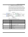
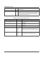
AUTOMATION
User manual
UM EN PROFINET CTRL DEV
PROFINET IO controller/device functions
AUTOMATION
User manual
PROFINET IO controller/device functions
2010-04-19
Designation:
UM EN PROFINET CTRL DEV
Revision:
00
This user manual is valid for:
PROFINET IO devices from Phoenix Contact
8037_en_00
PHOENIX CONTACT
UM EN PROFINET CTRL DEV
Please observe the following notes
In order to ensure the safe use of the product described, you have to read and understand
this manual. The following notes provide information on how to use this manual.
User group of this manual
The use of products described in this manual is oriented exclusively to qualified electricians
or persons instructed by them, who are familiar with applicable national standards and other
regulations regarding electrical engineering and, in particular, the relevant safety concepts.
Phoenix Contact accepts no liability for erroneous handling or damage to products from
Phoenix Contact or third-party products resulting from disregard of information contained in
this manual.
Explanation of symbols used and signal words
This is the safety alert symbol. It is used to alert you to potential personal injury
hazards. Obey all safety measures that follow this symbol to avoid possible
injury or death.
DANGER
This indicates a hazardous situation which, if not avoided, will result in death or serious
injury.
WARNING
This indicates a hazardous situation which, if not avoided, will result in death or serious
injury.
CAUTION
This indicates a hazardous situation which, if not avoided, could result in minor or
moderate injury.
The following types of messages provide information about possible property damage and
general information concerning proper operation and ease-of-use.
NOTE
This symbol and the accompanying text alerts the reader to a situation which may cause
damage or malfunction to the device, either hardware or software, or surrounding
property.
This symbol and the accompanying text provides additional information to the reader. It is
also used as a reference to other sources of information (manuals, data sheets, literature)
on the subject matter, product, etc.
PHOENIX CONTACT
8037_en_00
Please observe the following notes
General terms and conditions of use for technical documentation
Phoenix Contact reserves the right to alter, correct, and/or improve the technical
documentation and the products described in the technical documentation at its own
discretion and without giving prior notice, insofar as this is reasonable for the user. The
same applies to any technical changes that serve the purpose of technical progress.
The receipt of technical documentation (in particular data sheets, installation instructions,
manuals, etc.) does not constitute any further duty on the part of Phoenix Contact to furnish
information on alterations to products and/or technical documentation. Any other
agreement shall only apply if expressly confirmed in writing by Phoenix Contact. Please
note that the supplied documentation is product-specific documentation only and that you
are responsible for checking the suitability and intended use of the products in your specific
application, in particular with regard to observing the applicable standards and regulations.
Although Phoenix Contact makes every effort to ensure that the information content is
accurate, up-to-date, and state-of-the-art, technical inaccuracies and/or printing errors in
the information cannot be ruled out. Phoenix Contact does not offer any guarantees as to
the reliability, accuracy or completeness of the information. All information made available
in the technical data is supplied without any accompanying guarantee, whether expressly
mentioned, implied or tacitly assumed. This information does not include any guarantees
regarding quality, does not describe any fair marketable quality, and does not make any
claims as to quality guarantees or guarantees regarding the suitability for a special purpose.
Phoenix Contact accepts no liability or responsibility for errors or omissions in the content
of the technical documentation (in particular data sheets, installation instructions, manuals,
etc.).
The aforementioned limitations of liability and exemptions from liability do not apply, in so
far as liability must be assumed, e.g., according to product liability law, in cases of
premeditation, gross negligence, on account of loss of life, physical injury or damage to
health or on account of the violation of important contractual obligations. Claims for
damages for the violation of important contractual obligations are, however, limited to
contract-typical, predictable damages, provided there is no premeditation or gross
negligence, or that liability is assumed on account of loss of life, physical injury or damage
to health. This ruling does not imply a change in the burden of proof to the detriment of the
user.
8037_en_00
PHOENIX CONTACT
UM EN PROFINET CTRL DEV
Statement of legal authority
This manual, including all illustrations contained herein, is copyright protected. Use of this
manual by any third party is forbidden. Reproduction, translation, and public disclosure, as
well as electronic and photographic archiving or alteration requires the express written
consent of Phoenix Contact. Violators are liable for damages.
Phoenix Contact reserves all rights in the case of patent award or listing of a registered
design. Third-party products are always named without reference to patent rights. The
existence of such rights shall not be excluded.
How to contact us
Internet
Up-to-date information on Phoenix Contact products and our Terms and Conditions can be
found on the Internet at:
www.phoenixcontact.com
Make sure you always use the latest documentation.
It can be downloaded at:
www.phoenixcontact.net/catalog
Subsidiaries
If there are any problems that cannot be solved using the documentation, please contact
your Phoenix Contact subsidiary.
Subsidiary contact information is available at www.phoenixcontact.com.
Published by
PHOENIX CONTACT GmbH & Co. KG
Flachsmarktstraße 8
32825 Blomberg
Germany
Phone
+49 - (0) 52 35 - 3-00
Fax
+49 - (0) 52 35 - 3-4 12 00
PHOENIX CONTACT
P.O. Box 4100
Harrisburg, PA 17111-0100
USA
Phone
+1-717-944-1300
Should you have any suggestions or recommendations for improvement of the contents and
layout of our manuals, please send your comments to
[email protected]
PHOENIX CONTACT
8037_en_00
Table of contents
Table of contents
1
2
3
4
PROFINET IO controller/device functions ...............................................................................1-1
1.1
User group of the manual ................................................................................... 1-1
1.2
Basic knowledge required .................................................................................. 1-1
1.3
Additional PROFINET documentation ................................................................ 1-1
1.4
System requirements.......................................................................................... 1-2
1.5
PROFINET IO controller/device functions .......................................................... 1-3
Network topologies .................................................................................................................2-1
2.1
Topology 1: Mechatronic unit with lower-level compact controllers .................... 2-1
2.2
Topology 2: Four identical machine controllers under a
machine park controller ...................................................................................... 2-2
2.3
Topology 3: System control with lower-level subsystems ................................... 2-3
Description of a typical application
(all devices in one network) .....................................................................................................3-1
3.1
Information on how it was carried out ................................................................. 3-1
3.2
Typical application.............................................................................................. 3-4
3.3
Offline configuration............................................................................................ 3-7
3.3.1
Lower-level project .............................................................................. 3-7
3.3.2
Higher-level project ...........................................................................3-12
3.4
Online configuration..........................................................................................3-19
3.4.1
Preparing the PC for communication ................................................3-19
3.4.2
Configuring the ILC 170 ETH 2TX .....................................................3-20
3.4.3
Configuring the ILC 330 PN ..............................................................3-25
3.4.4
Observe startup behavior ..................................................................3-26
3.4.5
Checking the program start of the higher-level project ...................... 3-27
3.4.6
Checking the program start of the lower-level project .......................3-28
Description of a typical application
(devices in several networks) ..................................................................................................4-1
8037_en_00
4.1
Offline configuration............................................................................................ 4-3
4.1.1
Lower-level project .............................................................................. 4-3
4.1.2
RFC 470 PN-3TX higher-level/lower-level project ............................... 4-8
4.1.3
Higher-level project ...........................................................................4-14
4.2
Online configuration..........................................................................................4-22
4.2.1
Preparing the PC for communication ................................................4-22
4.2.2
Configuring the ILC 170 ETH 2TX .....................................................4-23
4.2.3
Configuring the RFC 470 PN-3TX .....................................................4-25
4.2.4
Configuring the ILC 330 PN ..............................................................4-26
4.2.5
Observe startup behavior ..................................................................4-30
PHOENIX CONTACT
i
UM EN PROFINET CTRL DEV
4.2.6
4.2.7
ii
PHOENIX CONTACT
Checking the program start of the higher-level project ...................... 4-32
Checking the program start of the lower-level project .......................4-33
8037_en_00
PROFINET IO controller/device functions
1
PROFINET IO controller/device functions
The "PROFINET IO controller/device functions (UM EN PROFINET CTRL DEV) user
manual provides an overview of the PROFINET communication system with device
functions. This system description provides support when installing, starting up or operating
a PROFINET device system. Examples show you how to program IO device diagnostics.
1.1
User group of the manual
Use this user manual if your are responsible for programming user programs or configuring,
starting up and servicing automation systems.
1.2
Basic knowledge required
The following knowledge is required to understand the user manual:
– General knowledge with regard to automation technology
– Knowledge on how to use computers or equipment similar to a PC
(e.g., programming devices) under the Windows operating system
– Knowledge of how to use PC WorX
– Good knowledge of the PROFINET IO communication method.
1.3
Additional PROFINET documentation
The PROFINET documentation is modular, providing you with optimum information.
Available
PROFINET documents
"PROFINET basics" user manual
UM EN PROFINET SYS
The manual describes PROFINET system basics.
This includes:
– PROFINET development
– PROFINET versions
– PROFINET properties
– PROFINET installation and startup
– PROFINET and wireless
8037_en_00
PHOENIX CONTACT
1-1
UM EN PROFINET CTRL DEV
Quick start guides
–
–
"Installing and starting up the starterkit 3.0" quick start guide
UM QS EN PROFINET STARTERKIT 3.0.
"Configuring INTERBUS devices in a PROFINET IO network using the example of
STEP 7"
UM QS EN PROFINET PROXY IB
Device-specific data sheets
The data sheets describe the specific properties of PROFINET IO devices.
These include:
– Function description
– Ordering data and technical data
– Local diagnostic and status indicators
– Pin assignment and connection example
– Programming data/configuration data
PROFINET documents
in preparation
–
–
"Acyclic communication" application note
AH EN PROFINET AZY KOM
"PROFINET diagnostics" application note
AH EN PROFINET DIAG
Make sure you always use the latest documentation.
It can be downloaded at:
www.phoenixcontact.net/catalog
1.4
System requirements
Please note that the PROFINET IO device function of the ILC170 ETH 2TX is only
available in the PC WorX software from version 6.00 Service Pack 2 or later (part of the
AUTOMATIONWORX Software Suite 2009 1.50 Service Pack 2).
The PC WorX Express software does not support these functions.
Firmware 3.5x for all controllers, including the PROFINET IO device function, is at least
required to use the PROFINET IO device functions.
1-2
PHOENIX CONTACT
8037_en_00
PROFINET IO controller/device functions
1.5
PROFINET IO controller/device functions
The master-slave procedure known from PROFIBUS was transferred to a providerconsumer model with PROFINET. A Provider generates and transmits data which the
Consumer receives and processes. In terms of communication all devices in the PROFINET
network have equal rights. The configuration specifies how the field devices are assigned
to a central control system. PROFINET IO divides the control devices into IO controllers and
IO devices. IO controllers are typically control systems (e.g., a central vehicle control).
The interface for IO devices was standardized by the PNO (Profibus User Organization)
(PROFINET IO and GSD). This allows control systems from various manufacturers to
communicate with IO devices. During configuration IO devices are assigned logically to an
IO controller.
Figure 1-1
How communication works
PROFINET system variables (PROFINET IO controller)
System variable
Type
Meaning
PNIO_FORCE_FAILSAFE
BOOL
All outputs are set to the safe state "0“.
PNIO_CONFIG_STATUS
BOOL
Status of the active configuration in the context manager
PNIO_CONFIG_STATUS_ACTIVE
BOOL
Communication is active.
PNIO_CONFIG_STATUS_READY
BOOL
The context manager is active.
PNIO_SYSTEM_BF
BOOL
An error occurred in the PROFINET network, that means, there is no
connection to at least one configured device. This value is not set if the
"Drive BF" parameter was set to FALSE for a device. This device is
removed from connection monitoring.
PNIO_SYSTEM_SF
BOOL
At least one device reported a system error (diagnostic alarm or
maintenance alarm).
PNIO_DIAG_AVAILABLE
BOOL
At least one device reported a diagnostic alarm with an active
connection.
PNIO_MAINTENANCE_REQUIRED
BOOL
At least one device reported the "maintenance demand" alarm with an
active connection.
8037_en_00
PHOENIX CONTACT
1-3
UM EN PROFINET CTRL DEV
PNIO_MAINTENANCE_DEMANDED BOOL
At least one device reported the "maintenance request" alarm with an
active connection.
PNIO_DATA_DIAG
If this bit is set, no device diagnostics is present.
PNIO_DATA_VALID
BOOL
The application program must receive information on whether a
PROFINET IO device is supplying valid data or not. For this reason, the
"PNIO_DATA_VALID" process date exists on each PROFINET IO
device. Only if this bit is set does the PROFINET device supply valid data
and all other process values are valid.
PROFINET system variables (PROFINET IO device)
System variable
Type
Meaning
PND_S1S1_PLC_RUN
BOOL
Status of the higher-level control system/IO controller
PND_S1S1_VALID_DATA_CYCLE
BOOL
The higher-level control system/IO controller has established
the connection.
PND_S1S1_OUTPUT_STATUS_GOOD
BOOL
I/O provider status of the higher-level control system/
IO controller
PND_S1S1_INPUT_STATUS_GOOD
BOOL
I/O consumer status of the higher-level control system/
IO controller
PND_S1S1_DATA_LENGTH
WORD
Process data length that was configured for the IO device.
PND_S1S1_OUTPUTS
PND_IO_512
[256]
[128]
[64]
[32]
OUT process data
Memory area for OUT process data that the IO device
receives from the higher-level control system/IO controller.
PND_S1S1_INPUTS
PND_IO_512
[256]
[128]
[64]
[32]
IN process data
Memory area for IN process data that the IO device receives
from the higher-level control system/IO controller.
1-4
PHOENIX CONTACT
8037_en_00
Network topologies
2
Network topologies
The following pages show three typical examples of network topologies.
These topology examples are to explain the dependence and/or independence of the
PROFINET IO controller/device functions.
The following hardware was used for the network structure:
ILC 330 PN
2988191-03
ILC 170 ETH 2TX
2916532-04
RFC 470 PN-3TX
2916600-07
FL SWITCH SMCS 4TX-PN 2989093-06
2.1
Figure 2-1
Topology 1: Mechatronic unit with lower-level
compact controllers
Topology 1: All devices in one network
Topology 1 describes a central concept with lower-level compact controllers. Every
compact controller (ILC 1xx) is an independent PROFINET IO device and handles a local
mechatronic unit with inputs and outputs. All controllers are available in a local network.
Realtime communication over the central controller (RFC 470 PN-3TX, ILC 3xx) takes place
over PROFINET. Controllers that are connected over a switch can be disconnected from
the network at any time.
8037_en_00
PHOENIX CONTACT
2-1
UM EN PROFINET CTRL DEV
2.2
Figure 2-2
Topology 2: Four identical machine controllers
under a machine park controller
Topology 2: Devices in several networks
Topology 2 describes a central concept with lower-level machine controllers.
Every machine controller (RFC 470 #2, #3, #4, #5) comprises a PROFINET IO device. This
machine controller comprises in parallel IO controllers with their own IO devices. The lowerlevel networks can use the identical IP address range since they are separated by the
controller.
The RFC #1 controller as well as the RFCs #2, #3 and RFCs #4, #5 on the device side are
located in a higher-level network. Being PROFINET IO devices, the individual I/Os are
located in a lower-level network.
2-2
PHOENIX CONTACT
8037_en_00
Network topologies
2.3
Figure 2-3
Topology 3: System control with lower-level
subsystems
Topology 3: Devices in several networks
Topology 3 describes a central concept with lower-level system controllers. Every controller
comprises a PROFINET IO device. This controller is also an IO controller with its own IO
devices. All controllers and IO devices are located in one network.
8037_en_00
PHOENIX CONTACT
2-3
UM EN PROFINET CTRL DEV
2-4
PHOENIX CONTACT
8037_en_00
Description of a typical application (all devices in one network)
3
Description of a typical application
(all devices in one network)
3.1
Information on how it was carried out
Alignment
The alignment of the data elements in the Inline controller memory can result in "data gaps"
when storing data in the memory. The compiler automatically fills these gaps with padding
bytes during the compiler process in order to prevent incorrect processing.
The disadvantage of the "automatic" filling of data gaps becomes apparent when data is
transmitted from the Inline controller to another controller. If this controller does not know the
memory algorithm of the Inline controller it will interpret the received data incorrectly.
It is therefore useful to program the filling of data gaps in your application program. Data
transmissions to other controllers can thus be taken into consideration. For example, use
byte arrays with an even number of bytes and/or word arrays in order to avoid data gaps in
your application program.
The following should be taken into consideration when creating the program:
– Create data types in flat structures, i.e., do not nest user-defined data types.
– Insert padding bytes manually in order to ensure the uniform size and layout of the data
types.
– When inserting padding bytes, please observe the memory alignment method of the
controllers used in the application (1-byte, 2-byte or 4-byte alignment).
8037_en_00
PHOENIX CONTACT
3-1
UM EN PROFINET CTRL DEV
Programming example with data gaps
The following program example shows how data gaps are filled.
Figure 3-1
Programming example with data gaps
Struct1 receives a padding byte after the ByteElement so that the WordElement is at a
WORD address (address that can be divided by 2 leaving no remainder). The alignment of
the overall structure is based on the data type used with maximum alignment. In this case
the WordElement specifies the alignment.
The size of Struct2 is calculated based on the elements used and the resulting alignment.
The corresponding number of padding bytes is inserted so that the size of the data type with
the value of the alignment can be divided by 2 leaving no remainder (data type size modulo
alignment = 0).
Struct3 does not receive any padding bytes as the maximum alignment corresponds to one
byte.
Due to the padding bytes that belong to the Struct2 structure, the Struct3 structure starts at
an even address. The number of padding bytes in array 1 corresponds to that of two
consecutive Struct2 structures.
3-2
PHOENIX CONTACT
8037_en_00
Description of a typical application (all devices in one network)
Programming example without data gaps
The following program shows an example of how data gaps may be filled in your application
program. Fill data gaps, which are to be expected due to the memory alignment, with
application data.
Figure 3-2
3.2
Programming example without data gaps
Typical application
In the following application all devices are in one network, see also the topology example on
page 2-1.
Figure 3-3
8037_en_00
Typical application
PHOENIX CONTACT
3-3
UM EN PROFINET CTRL DEV
The following devices are used for this application:
Device
Order No.
IP address
ILC 330 PN as master
2988191
192.168.0.5
ILC 170 ETH 2TX as device
2916532
192.168.0.7
FL SWITCH SMCS 4TX (optional) 2989093
Notebook as programming device
Figure 3-4
192.168.0.10
Typical application, all devices in one network
In this example, a project is created on the lower-level controller (ILC 170 PN) by requesting
the status variables of PROFINET communication (PND_S1S1). For this purpose, a
function block is created in structured text that sets the value "true" on the
ONBOARD_OUTPUT_BIT0 system variable. The LED is ON when the ILC 330 PN sends
the value "1".
In the example, a function block is used for logical ANDing. The
I_ILC170ETH1_0_PNIO_DATA_VALID and I_ILC170ETH_0_PNIO_APPL_RUN variables
(both system variables) map the status of the inputs to which the PNIO_FORCE_FAILSAFE
system variable is connected.
The PNIO_DATA_VALID system variable indicates for each PROFINET IO device whether
the connection to this PROFINET IO device was established successfully. Only if this bit is
set does the PROFINET IO device supply valid data and all other process values are active.
A negated result is linked to the PNIO_FORCE_FAILSAFE variable. The PROFINET
system is stable when the system variable PNIO_FORCE_FAILSAFE = 0. All outputs are
set according to the process data If PNIO_FORCE_FAILSAFE = 1 (at least one
PNIO_DATA_VALID variable set to 0), the safe state "0" is output for all PROFINET IO
device outputs.
3-4
PHOENIX CONTACT
8037_en_00
Description of a typical application (all devices in one network)
In addition, the value 1 is assigned to the PNArr_OUT[0] variable (user variable). This is
done via the negated status of the PNIO_FORCE_FAILSAFE system variable. The value 1
is converted in the BYTE data type, since the PROFINET IO process data (PND_IO_256)
are assigned as ARRAY OF BYTE data type for the variable.
8037_en_00
PHOENIX CONTACT
3-5
UM EN PROFINET CTRL DEV
3.3
3.3.1
•
Offline configuration
Lower-level project
Select the "New Project..." command from the "File" menu to create a new project using
a template.
The tree structure and the selection of the control system are now prepared.
•
Select the "ILC 170 ETH Rev. >01/3.50" control system and confirm your selection with
"OK".
Figure 3-5
•
•
Select the "File, Save Project As/Zip Project As..." command.
Enter a project name (here: ILC170_Device) and save the project.
Figure 3-6
3-6
PHOENIX CONTACT
Selecting the controller
Save project
8037_en_00
Description of a typical application (all devices in one network)
The following window opens:
Figure 3-7
•
•
Right-click on Logical POUs.
Insert the function block.
Figure 3-8
8037_en_00
PC WorX start screen
Inserting the function block
PHOENIX CONTACT
3-7
UM EN PROFINET CTRL DEV
•
•
Select the ST (Structured Text) language.
Name the block "Data_Acknowledge".
Figure 3-9
•
Open the worksheet by double-clicking on "Data_Acknowledge".
Figure 3-10
3-8
PHOENIX CONTACT
Selecting the programming language and naming the function block
Opening the worksheet
8037_en_00
Description of a typical application (all devices in one network)
•
Insert the following program to your worksheet.
Figure 3-11
Inserting the program
The ONBOARD-OUTPUT_BIT0 system variable and the PROFINET IO device status
variable PND_S1S1_INPUTS for the process data can be found under the
Global_Variables.
•
Select the maximum process data length of 256 bytes (PND_IO_256) for the data
exchange between master and device.
Figure 3-12
8037_en_00
Selecting the process data
PHOENIX CONTACT
3-9
UM EN PROFINET CTRL DEV
•
Afterwards insert the created function block in the "Main" worksheet using drag & drop.
Figure 3-13
•
•
3-10
PHOENIX CONTACT
Inserting the function block into the worksheet
Compile the project and save it.
Close the project.
8037_en_00
Description of a typical application (all devices in one network)
3.3.2
•
Higher-level project
Select the "New Project..." command from the "File" menu to create a new project using
a template.
The tree structure and the selection of the control system are now prepared.
•
Select the "ILC 330 PN Rev. > 01/4.6F/3.50" control system and confirm your selection
with "OK".
Figure 3-14
•
•
Select the "File, Save Project As/Zip Project As..." command.
Enter a project name (here: ILC330_Controller and save the project.
Figure 3-15
8037_en_00
Selecting the controller
Save project
PHOENIX CONTACT
3-11
UM EN PROFINET CTRL DEV
The following window opens:
Figure 3-16
3-12
PHOENIX CONTACT
Start screen
8037_en_00
Description of a typical application (all devices in one network)
•
•
First integrate the ILC 170 ETH 2TX as a PROFINET IO device into the bus structure.
Change to the bus structure. To do this, click on the "Bus Structure" icon in the
toolbar.
•
Insert the ILC 170 ETH 2TX as a device into the bus structure (right click).
Figure 3-17
8037_en_00
Inserting the ILC 170 ETH 2TX as a device in the bus structure
PHOENIX CONTACT
3-13
UM EN PROFINET CTRL DEV
The PROFINET device inserted will be displayed in the Bus Structure workspace. The IP
address is created depending on the IO controller address.
Figure 3-18
The ILC 170 ETH 2TX integrated as PROFINET device in the bus structure
The process data of the PROFINET device will be displayed in the Device Details
workspace of the "Process Data" tab.
Figure 3-19
3-14
PHOENIX CONTACT
Process data of the PROFINET device
8037_en_00
Description of a typical application (all devices in one network)
•
Switch to the IEC programming
•
•
Add the mapped function blocks.
Negate the output at the AND block.
Figure 3-20
and open the "Main" worksheet.
Adding function blocks
For the system variables for displaying the status of a PROFINET IO device, the process
data is generated automatically.
•
Switch to the process data assignment workspace.
•
In the top left window, "Symbols/Variables", select the program
(here: Main : Main).
•
Highlight the PROFINET IO device in the top right window.
•
Highlight the PNIO_APPL_RUN variable in the bottom right window.
•
Enable the context menu on the variable and select the "Create Variable" command. In
this case, a variable is generated automatically.
•
Proceed in the same way for the PNIO_DATA_VALID variable.
Figure 3-21
8037_en_00
Creating variables
PHOENIX CONTACT
3-15
UM EN PROFINET CTRL DEV
•
In addition, create the "PNArr_Out" variable with the "PND_IO_256" data type as "VAREXTERNAL".
Figure 3-22
•
•
•
•
•
Creating the "PNArr_Out" variable
To link the process data to the variables, proceed as follows:
In the top left window (Symbols/Variables) select "Default".
Highlight the PROFINET IO controller in the top right window.
Highlight the "ILC 170 ETH ..." variable in the bottom right window.
Connect the "PNArr_Out" variable to the "I256" process data item of the
ILC 170 ETH 2TX device.
The total available data width of 256 bytes was selected in this example. You can change it
later in the online configuration.
Figure 3-23
3-16
PHOENIX CONTACT
Connecting the "PNArr_Out" variable to the process data
8037_en_00
Description of a typical application (all devices in one network)
•
•
Switch to IEC programming and link the variables as shown in the figure below.
Add a negation to the output of the AND block.
The "PNIO_FORCE_FAILSAFE" system variable is used at the output of the AND block and
the input of the "NOT" block.
Figure 3-24
•
•
8037_en_00
Inserting and linking variables
Select the "0" array in the byte array by writing the field "[0]" after the "PNArr_Out"
variable.
Then compile the project and save it.
PHOENIX CONTACT
3-17
UM EN PROFINET CTRL DEV
3.4
Online configuration
3.4.1
•
Preparing the PC for communication
For configuration and parameterization assign an appropriate IP address for your PC
within the 192.168.0.x address area.
In this example the PC receives the address 192.168.0.10.
Figure 3-25
•
Assigning an IP address
Select the network card of your PC that is to be used for communication in the
"Tools/PROFINET..." menu of PC WorX.
Figure 3-26
Selecting the network card
Now the PC is ready for communications within the subnet.
3-18
PHOENIX CONTACT
8037_en_00
Description of a typical application (all devices in one network)
3.4.2
Configuring the ILC 170 ETH 2TX
Assigning IP settings
To set the IP address in PC WorX proceed as described below:
•
Open your project "ILC170_Device".
•
Establish an Ethernet connection between your PC and the controller.
•
In the PC WorX menu bar, select the
"Extras... BootP/SNMP/TFTP-Configuration..." menu.
Figure 3-27
•
Activate the "BootP server active" checkbox.
Figure 3-28
•
•
•
•
8037_en_00
Selecting "Extras/BootP/SNMP/TFTP-Configuration..."
Activate BootP server
Switch to the bus configuration workspace, see Figure 3-30
Select the controller node.
Select the "IP Settings" tab in the "Device Details" window.
Enter the MAC address of the controller. It is printed on the device and starts with
00.A0.45.
PHOENIX CONTACT
3-19
UM EN PROFINET CTRL DEV
PF
FA
RD1Y
ETH 85330
150
ILC -No.: 2900 .xx
/1 xx
er
Ord W: 00xx.xx.
/F
HW Addr.:
MAC
ET
ES
MR
OP
ST
E
UL
US
UM
FR
FF
Q2
Q1 4
Q
Q3
IL
I2
I1
I4
I3
I6
I5
I8
I7
G
RO
N/P
RU
T
SE
RE
G
PR
AC
LN
T
K
7805A012
Figure 3-29
Printed MAC address on the ILC 150 ETH controller
Figure 3-30
Entering the IP address
•
•
Perform a cold restart for the controller.
To do this, switch the supply voltage off and then on again after around 2 seconds.
The controller is assigned the IP address, which is specified in the project for the controller
(here: 192.168.0.7). The following message appears in the message window in the "Bus
Configurator" tab.
Figure 3-31
Message window
The IP address will now be permanently stored on the controller Flash memory.
3-20
PHOENIX CONTACT
8037_en_00
Description of a typical application (all devices in one network)
Switching on the PROFINET IO device function
The following applies to the devices:
ILC 170/330/350/370/390 PN / RFC 470 PN-3TX
By default upon delivery the PROFINET IO device function is switched off for every
controller.
•
Switch to the "Extended Settings" tab.
•
Select the "IO device status" item in the device details under "Network Settings".
•
Under "Settings", select "activated" in the pull-down menu.
Figure 3-32
•
•
Click on "Transmit".
In the "Settings Communication Path" dialog confirm with "OK" the suggested IP
address or the one you have selected for your application.
Figure 3-33
8037_en_00
Device function activated
Setting the communication path
PHOENIX CONTACT
3-21
UM EN PROFINET CTRL DEV
Successful execution of the service will be displayed in the status window.
Figure 3-34
Status window
To transfer the network settings you have to reset the IO controller.
•
Select the "Ethernet" item in the Device Details window under "Network Settings".
The device name in the higher-level project (ILC 170 ETH device) must match the device
name of the lower-level project (ILC 170 ETH).
•
In the "Activate Network Settings" area click the "Reset Control System" button.
Figure 3-35
3-22
PHOENIX CONTACT
Resetting the controller
8037_en_00
Description of a typical application (all devices in one network)
•
In the "Settings Communication Path" dialog confirm with "OK" the suggested IP
address or the one you have selected for your application.
Figure 3-36
Setting the communication path
Successful execution of the service will be displayed in the status window.
Figure 3-37
Status window
The input/output data ranges available for the ILC 170 ETH 2TX as PROFINET IO device
are displayed under "Network Settings" -> "PROFINET Device".
Figure 3-38
8037_en_00
Input/output data ranges
PHOENIX CONTACT
3-23
UM EN PROFINET CTRL DEV
To set the task to update the I/Os, select the device resource in the Bus Structure window.
•
Set the update task to "DEFAULT".
Figure 3-39
3.4.3
Setting the update task
Configuring the ILC 330 PN
To configure the ILC 330 PN controller, proceed as described in Section "Configuring the
ILC 170 ETH 2TX" on page 3-19.
Assigning IP settings
Open the higher-level project "ILC330_Controller" and proceed as described in Section
"Configuring the ILC 170 ETH 2TX" on page 3-19.
Please not the following modifications:
– Enter the MAC address of the ILC 330 PN controller.
– Assign the IP address 192.168.0.2.
To use the PROFINET device functions, the following conditions apply for the
"ILC330_Controller" project.
ILC 330 PN settings as PROFINET controller:
IP address:
192.168.0.2
Subnet mask
255.255.255.0
PROFINET device name:
ILC330PN1
ILC 170 ETH 2TX settings as PROFINET IO device:
IP address:
192.168.0.7
Subnet mask
255.255.255.0
PROFINET device name:
ILC170ETH1
Please make sure that the same PROFINET device name of the ILC 170 ETH (here:
ILC170ETH1) is used in the lower-level project as in the higher-level project for the
ILC 170 ETH as a device (here: ILC170ETH1).
3-24
PHOENIX CONTACT
8037_en_00
Description of a typical application (all devices in one network)
3.4.4
Observe startup behavior
Starting up the controller is the easiest way to check whether
– The controller is correctly parameterized
– The IO devices have the right name
– There are double names or double IP addresses in the system.
Compile the ILC330_Controller project with the bus configuration. There will be a warning
message if there is no application program. You can ignore this message.
Make sure that the controller has the IP address that was set in the project. Start the project
control dialog via the menu bar.
If the message "Timeout" appears after 10 seconds, the project and device addresses do
not match. It is also possible that the IP address of the computer has not been set correctly.
The controller can be reset from the project control dialog. The existing project will be
deleted. Start the download and perform a cold reset. Afterwards the BF LEDs must go out
on all devices.
To access the network status from the program, the following system variables are mapped
in the global variables of the programming environment. Activate the "Debug On" operating
mode and the values of these variables will be displayed.
8037_en_00
Global variable
Description
PNIO_CONFIG_STATUS_ACTIVE
Connection to these devices is being established
or has been completed.
PNIO_CONFIG_STATUS_READY
The connection establishment to the devices has
been completed.
PHOENIX CONTACT
3-25
UM EN PROFINET CTRL DEV
3.4.5
Checking the program start of the higher-level project
When the program is started correctly, the following screen will be shown in the Debug
mode:
Figure 3-40
Program status
The PNIO_FORCE_FAILSAVE variable is in the FALSE state, thus communication is
ensured and the outputs are set according to the process data.
If you remove the voltage connector of the ILC 170 2TX or change the device to the "Stop
Mode", the status of PNIO_FORCE_FAILSAFE will change to TRUE. All outputs will be set
to "0" and the value "1" is no longer transferred to the device.
Figure 3-41
3-26
PHOENIX CONTACT
Program status in "Stop Mode"
8037_en_00
Description of a typical application (all devices in one network)
3.4.6
Checking the program start of the lower-level project
The behavior described before can also be observed in the ILC170_Device project.
•
Please open the lower-level project of the ILC 170 ETH 2TX.
•
Then open the "Data_Acknowledge" POU and activate the Debug mode.
The following screen appears:
Figure 3-42
Program status active
The value 1 is in array [0] of the PND_S1S1_INPUTS. The ONBOARD_OUTPUT_BIT0
variable is TRUE and the LED is ON.
Figure 3-43
Program is stopped
When communication is interrupted by removing the voltage connector of the ILC 170
device or by changing into the "Stop Mode" through the ILC 330 PN, the value is set to "0".
If you need more detailed information, call the Diag+ diagnostic tool from PC WorX under
View-> Diag+. Here you connect explicitly to a controller and receive further information.
8037_en_00
PHOENIX CONTACT
3-27
UM EN PROFINET CTRL DEV
3-28
PHOENIX CONTACT
8037_en_00
Description of a typical application (devices in several networks)
4
Description of a typical application
(devices in several networks)
In the following application all devices are in several networks, see also the topology
example on page 2-2.
The following devices are used for this application:
8037_en_00
Device
Order No.
IP address
ILC 330 PN as master
2988191
192.168.1.3
RFC 470 PN-3TX as master
2916600
192.168.0.5
RFC 470 PN-3TX as device
2916600
192.168.1.5
ILC 170 ETH 2TX as device
2916532
192.168.0.7
FL SWITCH SMCS 4TX (optional) 2989093
-
Laptop (higher-level network 1)
192.168.1.10
Laptop (lower-level network 2)
192.168.0.10
PHOENIX CONTACT
4-1
UM EN PROFINET CTRL DEV
Figure 4-1
Typical application, devices in several networks
In this example, a project is created on the lower-level controller (ILC 170 ETH 2TX) by
requesting the status variables of PROFINET communication (PND_S1S1). For this
purpose, a function block is created in structured text that sets the value "true" on the
ONBOARD_OUTPUT_BIT0 system variable. The LED is ON when the ILC 330 PN sends
the value "1". This example uses two networks, the RFC 470 PN-3TX links the process data
between ILC 330 PN and ILC 170 ETH 2TX. The program is identical with the first example
application.
In the example, a function block is used for logical ANDing. The PNIO_DATA_VALID and
PNIO_APPL_RUN variables (both system variables) of the RFC map the status of the
inputs to which the PNIO_FORCE_FAILSAFE system variable is connected.
The PNIO_DATA_VALID system variable indicates for each PROFINET IO device whether
the connection to this PROFINET IO device was established successfully. Only if this bit is
set does the PROFINET IO device supply valid data and all other process values are active.
A negated result is linked to the PNIO_FORCE_FAILSAFE variable. The PROFINET
system is stable when the system variable PNIO_FORCE_FAILSAFE = 0. All outputs are
set according to the process data If PNIO_FORCE_FAILSAFE = 1 (at least one
PNIO_DATA_VALID variable set to 0), the safe state "0" is output for all PROFINET IO
device outputs.
Assign the value 1 to the PNArr_OUT[0] variable (user variable). This is done via the
negated status of the PNIO_FORCE_FAILSAFE system variable. The value 1 is converted
in the BYTE data type, since the PROFINET process data (PND_IO_256) are assigned as
ARRAY OF BYTE data type for the variable.
4-2
PHOENIX CONTACT
8037_en_00
Description of a typical application (devices in several networks)
4.1
4.1.1
•
Offline configuration
Lower-level project
Select the "New Project..." command from the "File" menu to create a new project using
a template.
The tree structure and the selection of the control system are now prepared.
•
Select the "ILC 170 ETH Rev. >01/3.50" control system and confirm your selection with
"OK".
Figure 4-2
•
•
Select the "File, Save Project As/Zip Project As..." command.
Enter a project name (here: ILC170_Device) and save the project.
Figure 4-3
8037_en_00
Selecting the controller
Save project
PHOENIX CONTACT
4-3
UM EN PROFINET CTRL DEV
The following window opens:
Figure 4-4
•
•
Right-click on Logical POUs.
Insert the function block.
Figure 4-5
4-4
PHOENIX CONTACT
PC WorX start screen
Inserting the function block
8037_en_00
Description of a typical application (devices in several networks)
•
•
Select the ST (Structured Text) language.
Name the block "Data_Acknowledge".
Figure 4-6
•
Open the worksheet by double-clicking on "Data_Acknowledge".
Figure 4-7
8037_en_00
Selecting the programming language and naming the function block
Opening the worksheet
PHOENIX CONTACT
4-5
UM EN PROFINET CTRL DEV
•
Insert the following program to your worksheet.
Figure 4-8
Inserting the program
The ONBOARD-OUTPUT_BIT0 system variable and the PROFINET IO device status
variable PND_S1S1_INPUTS for the process data can be found under the
Global_Variables.
•
Select the process data length of 256 bytes (PND_IO_256) for the data exchange
between master and device.
Figure 4-9
4-6
PHOENIX CONTACT
Selecting the process data
8037_en_00
Description of a typical application (devices in several networks)
•
Afterwards insert the created function block in the "Main" worksheet using drag & drop.
Figure 4-10
•
•
8037_en_00
Inserting the function block into the worksheet
Compile the project and save it.
Close the project.
PHOENIX CONTACT
4-7
UM EN PROFINET CTRL DEV
4.1.2
•
RFC 470 PN-3TX higher-level/lower-level project
Select the "New Project..." command from the "File" menu to create a new project using
a template.
The tree structure and the selection of the control system are now prepared.
•
Select the "RFC 470 PN-3TX Rev. > 00/4.6F/3.50" control system and confirm your
selection with "OK".
Figure 4-11
•
•
Select the "File, Save Project As/Zip Project As..." command.
Enter a project name (here: RFC470_Controller_Device and save the project.
Figure 4-12
4-8
PHOENIX CONTACT
Selecting the controller
Save project
8037_en_00
Description of a typical application (devices in several networks)
The following window opens:
Figure 4-13
•
•
Right-click on Logical POUs.
Insert the function block.
Figure 4-14
8037_en_00
PC WorX start screen
Inserting the function block
PHOENIX CONTACT
4-9
UM EN PROFINET CTRL DEV
•
•
Select the ST (Structured Text) language.
Name the block "Data_Acknowledge".
Figure 4-15
•
Open the worksheet by double-clicking on "Data_Acknowledge".
Figure 4-16
4-10
PHOENIX CONTACT
Selecting the programming language and naming the function block
Opening the worksheet
8037_en_00
Description of a typical application (devices in several networks)
•
Insert the following program to your worksheet.
Figure 4-17
Inserting the program
The PNArr_OUT[0] variable is linked with the PROFINET device status variable
PND_S1S1_INPUTS, so that the ILC 170 device can call the status of the
ONBOARD_OTPUT_BIT0 system variable.
Select the maximum process data length of 256 bytes (PND_IO_256) for the data exchange
between ILC 330 PN, RFC 470 PN-3TX and ILC 170 ETH 2TX.
The RFC 470 PN-3TX can transmit up to 512 bytes of data, however, the process data
length is adapted to the ILC 170 ETH 2TX. It can transmit up to 256 bytes.
Figure 4-18
8037_en_00
Creating the variables
PHOENIX CONTACT
4-11
UM EN PROFINET CTRL DEV
•
Afterwards insert the created function block in the "Main" worksheet using drag & drop.
Figure 4-19
•
4-12
PHOENIX CONTACT
Inserting the function block into the worksheet
Compile the project and save it.
8037_en_00
Description of a typical application (devices in several networks)
Assigning process data
•
•
Switch to the process data assignment workspace.
In the top left window, "Symbols/Variables", select the "System Variables" program.
•
•
•
•
Highlight the PROFINET IO device in the top right window.
Highlight the I256 process data item in the bottom right window.
Highlight the PNArr_OUT variable in the bottom left window.
Enable the context menu on the variable and select the "Connect" command.
Figure 4-20
•
8037_en_00
Linking process data
Compile, save, and close the project.
PHOENIX CONTACT
4-13
UM EN PROFINET CTRL DEV
4.1.3
•
Higher-level project
Select the "New Project..." command from the "File" menu to create a new project using
a template.
The tree structure and the selection of the control system are now prepared.
•
Select the "ILC 330 PN Rev. > 01/4.6F/3.50" control system and confirm your selection
with "OK".
Figure 4-21
•
•
Select the "File, Save Project As/Zip Project As..." command.
Enter a project name (here: ILC330_Controller and save the project.
Figure 4-22
4-14
PHOENIX CONTACT
Selecting the controller
Save project
8037_en_00
Description of a typical application (devices in several networks)
The following window opens:
Figure 4-23
8037_en_00
Start screen
PHOENIX CONTACT
4-15
UM EN PROFINET CTRL DEV
Integrating the RFC 470 PN-3TX as PROFINET IO device
The following section describes how you integrate the RFC 470 PN-3TX as PROFINET
device in the "ILC330_Controller" project.
•
Change to the bus structure. To do this, click on the "Bus Structure" icon in the
toolbar.
•
Insert the RFC 470 PN-3TX as a device into the bus structure (right click).
Figure 4-24
4-16
PHOENIX CONTACT
Insert the RFC 470 PN-3TX as a device into the bus structure
8037_en_00
Description of a typical application (devices in several networks)
The PROFINET device inserted will be displayed in the Bus Structure workspace. The IP
address is created depending on the IO controller address.
Figure 4-25
The RFC 470 PN-3TX integrated as a PROFINET IO device in the bus
structure
The process data of the PROFINET device will be displayed in the Device Details
workspace of the "Process Data" tab.
Figure 4-26
•
•
•
Process data of the PROFINET IO device
Replace the EA512 I/O module with the EA256 I/O module of the RFC. As a device the
lower-level ILC 170 ETH 2TX can transmit up to 256 bytes.
Delete the EA512 I/O module (right click).
Drag the EA256 I/O module in the bus structure (left click).
The RFC 470 PN-3TX is now available as PROFINET IO device in the "ILC330_Controller"
PC WorX project.
8037_en_00
PHOENIX CONTACT
4-17
UM EN PROFINET CTRL DEV
•
Switch to the IEC programming
•
•
•
Add the mapped function blocks.
Create the following variables at the links as specified.
Negate the output at the AND block.
Figure 4-27
•
4-18
PHOENIX CONTACT
and open the "Main" worksheet.
Adding function blocks
Save the modified main program.
8037_en_00
Description of a typical application (devices in several networks)
Assigning process data
For the system variables for displaying the status of a PROFINET IO device, the process
data is generated automatically.
•
Switch to the process data assignment workspace.
•
In the top left window, "Symbols/Variables", select the program
(here: Main : Main).
•
Highlight the PROFINET IO device in the top right window.
•
Highlight the PNIO_DATA_VALID variable in the bottom right window.
•
Highlight the PNIO_DATA_VALID variable in the bottom left window.
•
Enable the context menu on the variable and select the "Connect" command.
•
Proceed in the same way for the PNIO_APPL_RUN variable.
Figure 4-28
•
In addition, create the "PNArr_Out" variable with the "PND_IO_256" data type as "VAREXTERNAL".
Figure 4-29
8037_en_00
Linking variables
Creating the "PNArr_Out" variable
PHOENIX CONTACT
4-19
UM EN PROFINET CTRL DEV
•
Connect the "PNArr_Out" variable to the "I256" process data item of the
RFC 470 PN-3TX device.
The total available data width of 256 bytes was selected in this example. You can change it
later in the online configuration.
Figure 4-30
•
Switch to IEC programming and link the variables as shown in the figure below.
Figure 4-31
•
•
4-20
PHOENIX CONTACT
Connecting the "PNArr_Out" variable to the process data
Inserting and linking variables
Select the "0" array in the byte array by writing the field "[0]" after the "PNArr_Out"
variable.
Then compile the project and save it.
8037_en_00
Description of a typical application (devices in several networks)
4.2
Online configuration
4.2.1
•
For configuration and parameterization assign an appropriate IP address for your PC
within the 192.168.0.x address area. In this example the PC receives the address
192.168.0.10.
Figure 4-32
•
Preparing the PC for communication
Assigning an IP address
Select the network card of your PC that is to be used for communication in the
"Tools/PROFINET..." menu of PC WorX.
Figure 4-33
Selecting the network card
Now the PC is ready for communications within the subnet.
Set the address 192.168.1.10 for the higher-level network with the ILC 330 PN as a
master and the RFC 470 PN-3TX as a device. Set the address 192.168.0.10 for the lowerlevel network with the RFC 470 PN-3TX as a master and the ILC 170 ETH 2TX as a
device.
8037_en_00
PHOENIX CONTACT
4-21
UM EN PROFINET CTRL DEV
4.2.2
Configuring the ILC 170 ETH 2TX
Assigning IP settings
To set the IP address in PC WorX proceed as described below:
•
Open your project "ILC170_Device".
•
Establish an Ethernet connection between your PC and the controller.
•
In the PC WorX menu bar, select the
"Extras... BootP/SNMP/TFTP-Configuration..." menu.
Figure 4-34
•
Activate the "BootP server active" checkbox.
Figure 4-35
•
•
•
•
4-22
PHOENIX CONTACT
Selecting "Extras/BootP/SNMP/TFTP-Configuration..."
Activate BootP server
Switch to the bus configuration workspace, see Figure 4-37
Select the controller node.
Select the "IP Settings" tab in the "Device Details" window.
Enter the MAC address of the controller. It is printed on the device and starts with
00.A0.45.
8037_en_00
Description of a typical application (devices in several networks)
PF
FA
RD1Y
ETH 85330
150
ILC -No.: 2900 .xx
/1 xx
er
Ord W: 00xx.xx.
/F
HW Addr.:
MAC
ET
ES
MR
OP
ST
E
UL
US
UM
FR
FF
Q2
Q1 4
Q
Q3
IL
I2
I1
I4
I3
I6
I5
I8
I7
G
RO
N/P
RU
T
SE
RE
G
PR
AC
LN
T
K
7805A012
Figure 4-36
Printed MAC address on the ILC 150 ETH controller
Figure 4-37
Entering the IP address
•
•
Perform a cold restart for the controller.
To do this, switch the supply voltage off and then on again after around 2 seconds.
The controller is assigned the IP address, which is specified in the project for the controller
(here: 192.168.0.7). The following message appears in the message window in the "Bus
Configurator" tab.
Figure 4-38
Message window
The IP address will now be permanently stored on the controller Flash memory.
8037_en_00
PHOENIX CONTACT
4-23
UM EN PROFINET CTRL DEV
4.2.3
Configuring the RFC 470 PN-3TX
By default upon delivery the diagnostic display has the following status:
Figure 4-39
Diagnostic display
The initial assignment of the IP settings can generally always be carried out using the
diagnostic display.
When using the PC WorX software, the initial assignment of the IP settings can be carried
out with BootP or using the COM1 serial interface.
•
If the Remote Field Controller already has IP settings that are valid in your network, you
can modify the IP settings via the network using PC WorX.
•
Set the RFC 470 PN-3TX to the mapped IP address 192.168.0.5. It can be accessed in
the network after a restart of the device.
Figure 4-40
LAN1 configuration display
The procedure for assigning the IP settings is essentially the same for the LAN1
(LAN1.1/LAN1.2) and LAN 2 interfaces. The following describes the assignment of the IP
settings at the LAN1 interface as an example. The LAN1.1/LAN1.2 interfaces are switched
internally. Thus, both ports can be accessed using the IP settings defined.
4-24
PHOENIX CONTACT
8037_en_00
Description of a typical application (devices in several networks)
For the LAN2 interface proceed as in the previous example, however, set the IP address to
192.168.1.5. The RFC 470 PN-3TX communicates with this address as a device.
NOTE:
The IP address of your PC must be in the same subnet as the LAN1 or LAN2 interface of
the RFC 470 PN-3TX. Only then is communication for configuration of the ILC 170 ETH
2TX possible.
In this case the modification was done via the LAN1 interface (192.168.0.x subnet).
4.2.4
Configuring the ILC 330 PN
Assigning IP settings
•
•
When assigning the IP settings for the ILC 330 PN, please proceed in the same way as
for the ILC 170 ETH 2TX, see "Configuring the ILC 170 ETH 2TX" on page 4-22.
Open the "ILC330_Controller" project.
Please not the following modifications:
Connect the network cable of your PC to the switch. Now you have established a connection
from the PC to the ILC 330 PN.
– BootP server is active
– Enter the MAC address of the ILC 330 PN controller.
– Assign the IP address 192.168.1.2.
Switching on the IO PROFINET device function
The following applies to the devices:
ILC 170/330/350/370/390 PN / RFC 470 PN-3TX
By default upon delivery the PROFINET device function is switched off for every controller.
To switch it on, start your existing project (in the example here: "ILC170_Device") in PC
WorX and activate the PROFINET device function as follows:
•
Switch to the "Extended Settings" tab.
•
Select the "IO device status" item in the device details under "Network Settings".
•
Under "Settings", select "activated" in the pull-down menu.
8037_en_00
PHOENIX CONTACT
4-25
UM EN PROFINET CTRL DEV
Figure 4-41
•
•
Device function activated
Click on "Transmit".
In the "Settings Communication Path" dialog confirm with "OK" the suggested IP
address or the one you have selected for your application.
Figure 4-42
Setting the communication path
Successful execution of the service will be displayed in the status window.
Figure 4-43
Status window
To transfer the network settings you have to reset the IO controller.
4-26
PHOENIX CONTACT
8037_en_00
Description of a typical application (devices in several networks)
•
Select the "Ethernet" item in the Device Details window under "Network Settings".
The device name in the higher-level project (ILC 170 ETH device) must match the device
name of the lower-level project (ILC 170 ETH).
•
In the "Activate Network Settings" area click the "Reset Control System" button.
Figure 4-44
•
In the "Settings Communication Path" dialog confirm with "OK" the suggested IP
address or the one you have selected for your application.
Figure 4-45
8037_en_00
Resetting the controller
Setting the communication path
PHOENIX CONTACT
4-27
UM EN PROFINET CTRL DEV
Successful execution of the service will be displayed in the status window.
Figure 4-46
Status window
The input/output data ranges available for the ILC 170 ETH 2TX as PROFINET IO device
are displayed under "Network Settings" -> "PROFINET Device".
Figure 4-47
Input/output data ranges
Setting the update task
To set the update task, select the device resource in the Bus Structure window.
•
Set the update task to "DEFAULT".
Figure 4-48
4-28
PHOENIX CONTACT
Setting the update task
8037_en_00
Description of a typical application (devices in several networks)
4.2.5
Observe startup behavior
To use the PROFINET device functions, the following conditions apply for the
"ILC330_Controller" project.
Higher-level controller:
ILC 330 PN
Controller settings:
IP address:
192.168.1.2
Subnet mask:
255.255.255.0
PROFINET device name: ILC330PN1
RFC 470 PN-3TX settings as a PROFINET IO device
IP address:
192.168.1.5
Subnet mask:
255.255.255.0
PROFINET device name: RFC470PN1
To use the PROFINET device functions, the following conditions apply for the
"RFC470_Device" project.
RFC 470 PN-3TX settings as a PROFINET IO controller
IP address:
192.168.0.5
Subnet mask:
255.255.255.0
PROFINET device name:
RFC470PN1
ILC 170 ETH 2TX settings as PROFINET IO device:
IP address:
192.168.0.7
Subnet mask:
255.255.255.0
PROFINET device name:
ILC170ETH1
Please make sure that the same PROFINET device name of the RFC 470 PN-3TX IO
controller (here: RFC470PN1) is used in the lower-level project as in the higher-level
project for the RFC 470 PN-3TX as a device (here: RFC140PN1).
Starting up the controller is the easiest way to check whether
– The controller is correctly parameterized
– The I/O devices have the right name
– There are double names or double IP addresses in the system.
Make sure that the controller has the IP address that was set in the project. Start the project
control dialog via the menu bar.
If the message "Timeout" appears after 10 seconds, the project and device addresses do
not match. It is also possible that the IP address of the computer has not been set correctly.
8037_en_00
PHOENIX CONTACT
4-29
UM EN PROFINET CTRL DEV
The controller can be reset from the project control dialog. The existing project will be
deleted. Start the download and perform a cold reset. Afterwards the BF LEDs must go out
on all devices.
To access the network status from the program, the following system variables are mapped
in the global variables of the programming environment. Activate the "Debug On" operating
mode and the values of these variables will be displayed.
4-30
PHOENIX CONTACT
Global variable
Description
PNIO_CONFIG_STATUS_ACTIVE
Connection to these devices is being established
or has been completed.
PNIO_CONFIG_STATUS_READY
The connection establishment to the devices has
been completed.
8037_en_00
Description of a typical application (devices in several networks)
4.2.6
•
Checking the program start of the higher-level project
Open the "ILC330_Controller" project.
When the program is started correctly, the following screen will be shown in the Debug
mode:
Figure 4-49
Program status
The PNIO_FORCE_FAILSAVE variable is in the FALSE state, thus communication is
ensured and the outputs are set according to the process data.
If you remove the voltage connector of the RFC 470 PN-3TX or change the device to the
"Stop Mode", the status of PNIO_FORCE_FAILSAFE will change to TRUE. All outputs will
be set to "0" and the value "1" is no longer transferred to the device.
Figure 4-50
8037_en_00
Program status in "Stop Mode"
PHOENIX CONTACT
4-31
UM EN PROFINET CTRL DEV
4.2.7
Checking the program start of the lower-level project
The behavior described before can also be observed in the ILC170_Device project. Please
note that the RFC 470 PN-3TX is operating as a master and as a slave at the same time. It
acts as the link between the ILC 330 PN controller and the ILC 170 2TX controller.
•
Please open the lower-level project of the ILC 170 ETH 2TX.
•
Then open the "Data_Acknowledge" POU and activate the Debug mode. The following
screen appears:
Figure 4-51
Program status active
The value 1 is in array [0] of the PND_S1S1_INPUTS. The ONBOARD_OUTPUT_BIT0
variable is TRUE and the Q1 LED on the ILC 170 2TX is ON. Now switch the PROFINET IO
controller (ILC 330 PN and/or RFC 470 PN-3TX) to stop. Communications is terminated and
the value is set to 0. The LED goes out as well, because the ONBOARD_INPUT_BIT0
variable is reset to FALSE.
Figure 4-52
Program is stopped
When communication is interrupted by removing the voltage connector of the ILC 170
device, a BF error appears on the RFC display at the PROFINET controller.
If you need more detailed information, call the Diag+ diagnostic tool from PC WorX under
View-> Diag+. Here you connect explicitly to a controller and receive further information.
4-32
PHOENIX CONTACT
8037_en_00