1
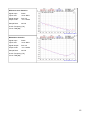
Manual for DBO1
Version 1.0.0
04.12.2012
© Four Audio GmbH & Co. KG 2012
Four Audio GmbH & Co. KG
Bergdriesch 24-26
52062 Aachen
Germany
Phone:. +49 241 4758 3170
Fax: +49 241-4758 3169
Seat: Aachen,
Entry in the commercial
register at the Local Court
Aachen: HRA6830
Partner liable to
unlimited extent:
our Audio Verwaltungsgesellschaft mbH,
Seat: Aachen
Entry in the commercial register at the local court
Aachen: HRB 14189
Managing director:
Dr.-Ing. Rainer Thaden
Contents
1
2
3
4
5
6
7
8
9
Important Safety Information......................................................................................................3
EC Declaration of Conformity.....................................................................................................4
Product Specifications.................................................................................................................5
DBO1 Inputs/Outputs..................................................................................................................6
4.1 Analog Outputs....................................................................................................................6
4.2 Digital Outputs.....................................................................................................................6
4.3 Ethernet Jacks......................................................................................................................7
4.4 Word Clock Input.................................................................................................................7
4.5 Word Clock Output..............................................................................................................7
Front panel...................................................................................................................................8
Basic Usage..................................................................................................................................9
Network Setup...........................................................................................................................10
7.1 Troubleshooting Switch Configuration and Cabling..........................................................11
FAQ............................................................................................................................................12
8.1 Why does the DBO1 not detect the sample rate automatically?........................................12
8.2 Why does the DBO1 not play audio if connected directly to a computer with Dante
Virtual Soundcard as external soundcard?................................................................................12
Audio Performance Measurements............................................................................................13
2
1 Important Safety Information
This device has been manufactured and tested with your safety in mind. However, improper use can
result in potential electric shock or fire hazards.
To avoid defeating the safeguards that have been built into the device, please observe the precautions
discussed in this document.
Warnings on the device
The lightning flash with arrowhead symbol, within a triangle, is intended to alert you to the presence of
uninsulated “dangerous” voltages within your device’s enclosure that may be of sufficient magnitude to
constitute a risk of electric shock to persons.
The exclamation point within a triangle is intended to alert you to the presence of important instructions
in the literature accompanying the device.
Other warnings
TO REDUCE THE RISK OF ELECTRIC SHOCK, DO NOT REMOVE THE COVER OF THE DEVICE.
THERE ARE NO USER-SERVICEABLE PARTS INSIDE IT.
TO REDUCE THE RISK OF FIRE OR ELECTRIC SHOCK, DO NOT EXPOSE THIS DEVICE TO RAIN
OR MOISTURE.
DO NOT PERFORM ANY SERVICING UNLESS YOU ARE QUALIFIED TO DO SO BY FOUR AUDIO.
REFER ALL SERVICING TO QUALIFIED SERVICE PERSONNEL.
SERVICING THE DEVICE YOURSELF WILL INVALIDATE THE WARRANTY.
Ventilation
Slots and openings in the casing of the device are provided for ventilation, to ensure reliable operation
of the device and to protect it from overheating.
Never block the ventilation openings by placing the device on a bed, sofa, rug or other similar surface;
Never cover the ventilation openings with items such as newspapers, table-cloths etc.
Do not place the device in a built-in installation such as a bookcase or rack unless proper ventilation is
provided or you have adhered to the manufacturer’s instructions;
Water and moisture
Do not expose this device to dripping or splashing and ensure that no objects filled with liquids, such as
vases, are placed on the device
SAVE THIS INFORMATION FOR FUTURE REFERENCE
3
2 EC Declaration of Conformity
An example of this equipment has been tested and found to comply with the following European and
international Standards for Electromagnetic Compatibility and Electrical Safety:
Radiated Emissions (EU):
EN55103-1 (1996)
RF Immunity (EU):
EN55103-2 (1996)
Electrical Safety (EU):
EN60065 (1993)
Manufacturer's Name & Address
Four Audio GmbH & Co. KG
Bergdriesch 24-26
52062 Aachen
Germany
Product Name
DBO1
Aachen, Dec-06-2012
Rainer Thaden
4
3 Product Specifications
DBO1 without optional AES output modul
Analog Outputs 8 balanced XLR
Ethernet
3 RJ-45
Word clock
1 Input / 1 output, both BNC type
Samplingrates
44,1 / 48 / 88,2 / 96 / 176,4 / 192 kHz
Resolution
24 bit
DBO1 with optional AES output modul
Analog Outputs 8 balanced XLR
Digital Outputs
4 AES/EBU, balanced XLR
Ethernet
3 RJ-45
Word clock
1 Input / 1 output, both BNC type
Samplingrate
44,1 / 48 / 88,2 / 96 / 176,4 / 192 kHz
Resolution
24 bit
Audio Performance
Analog Outputs
Max. Output Level
Dynamic Range
THD @ +4 dBu output level
DIM100 @ +16 dBu output level
+18 dBu
118 dB(A)
115 dB(lin)
-114 dB
-87,4 dB
5
4 DBO1 Inputs/Outputs
•
8 analog outputs (balanced XLR)
•
4 digital AES/EBU outputs (balanced XLR) (optional)
•
3 Ethernet jacks (EtherCon)
•
1 Word Clock input (BNC)
•
1 Word Clock output (BNC)
4.1 Analog Outputs
The 8 analog outputs provide a dynamic range of 118 dB(A) with a maximum output voltage of 18 dBu.
Following functions will be available in future:
–
Attenuation
-40 dB .. 0 dB in 0.5 dB steps
–
Phase Invert
0° / 180°
–
Mute
On / Off
Bold values are default values. All functions can be set individually for each channel.
Output jack
Function
1
Dante Channel 1
2
Dante Channel 2
3
Dante Channel 3
4
Dante Channel 4
5
Dante Channel 5
6
Dante Channel 6
7
Dante Channel 7
8
Dante Channel 8
4.2 Digital Outputs
As digital outputs 4 balanced AES/EBU outputs are provided. Functions provided for analog outputs are
not available for digital Outputs. Digital outputs provide same audio signals as analog outputs, because
DBO1 is a 8 channel device.
Output jack
Function
1
Left Channel = Dante Channel 1
Right Channel = Dante Channel 2
2
Left Channel = Dante Channel 3
Right Channel = Dante Channel 4
3
Left Channel = Dante Channel 5
Right Channel = Dante Channel 6
4
Left Channel = Dante Channel 7
Right Channel = Dante Channel 8
6
4.3 Ethernet Jacks
The DBO1 has 3 RJ-45 ethernet connectors with different functions:
PRI
Connect to Dante Primary Network
SEC
Connect to Dante Secondary Network (Redundant mode)
LAN
Connect non Dante devices here, e.g. a device which is to be controlled or monitored via
ethernet or a computer for command & control.
4.4 Word Clock Input
For synchronizing multiple clock domains, the DBO1 provides a word clock input. Connect the word
clock output of the clock domain that you want to be the master clock (e.g. an analog sound card
providing a WC output.
Clock Status View
Slave To External Word Clock: where a device can be slaved to an external Word Clock the value 'Yes'
(and a check box) will appear in this column. When checked, this will force the device to derive its local
clock from the external word clock source. This will also ensure that this Dante device becomes master
clock for the relevant clock domain (unless another device has 'Preferred Master' selected). It is not
normal practice to configure more than one device per clock domain with an external clock source. In
this case, the user is assumed to have synchronized external word clock sources (e.g. house clock).
Where a device does not support slaving to an external Word Clock the value in this column will be 'Not
Supported'.
4.5 Word Clock Output
If you want the DBO1 to be the master clock for the audio network consisting of multiple clock domains,
connect the word clock output to the word clock input of a device in a second clock domain.
7
5 Front panel
The front panel features several signalling LEDs and a multi-purpose push button.
The network display section consists of several status LEDs for each network port.
Element
Function / Meaning
GIG LINK:
Port is connected to a gigabit network
LINK/ACT:
Port is connected to a network, blinks on network activity
REDUNDANT:
Secondary port is configured for DANTE redundant mode
LOCKED:
Device is locked to the network PTP clock
LOCATOR:
blinks 10 times when using the identify function in the Dante Controller software
SAMPLE RATE:
displays the sample rate that the Dante card is using
The output display section consists of 4 status LEDs for each channel.
Element
Function / Meaning
SIGNAL:
signal level is above -40 dBFS (-22 dBu)
MODIFIED:
analog output settings are different from default settings
SUBSCRIBED:
a flow is patched to this output
WARNING/ERROR:
subscribed flow is not present in DANTE network
ANY KEY
provided for future features.
Current function: LED test for all LEDs except GIG LINK and LINK/ACT.
Available features are depending on the firmware version. For latest information
visit http://www.four-audio.com/key
8
6 Basic Usage
Basically, the DBO1 is just a break out box which converts Dante flows to analog and AES/EBU signals.
There is no special handling or configuration which is not covered by basic Dante features.
All Dante features can be configured and monitored with Dante Controller which is a software
application provided by Audinate, the inventor of Dante. Dante Controller and its user manual can be
downloaded from Audinate's homepage:
www.audinate.com
Home => Support => Software => Downloads => Dante Controller
If you are not familiar with the Dante Audio network we strictly recommend to read
the user manual of the Dante Controller software first and check the FAQ!
FAQ http://dev.audinate.com/kb/webhelp/home.htm
Most of the options, features and behaviour which a user expects to be device specific are actually
Dante specific. Thus, most of the explanations below are taken from the Dante Controller user manual.
These passages are highlighted in grey.
Please ensure to use latest version of Dante Controller: 3.2.9.2 or higher
9
7 Network Setup
Automatic network configuration
A Dante-enabled device connected to a network will automatically set up its own network configuration,
including its IP address.
If the network has a DHCP server, which may be the case for installed networks, it will receive its IP
configuration using the standard DHCP protocol.
On a network without a DHCP server, which may be the case for temporary or smaller networks, the
Dante-enabled device will automatically assign itself an address using link local protocols, in the same
way PCs and printers often do.
DBO1 supports redundant audio routing and switching between Redundant and Switched mode.
Redundancy
Many Dante devices support redundant audio routing. These devices have two network interfaces,
labelled primary and secondary. Primary interfaces should be connected to one physical network. If
redundancy is being used, secondary interfaces should be connected to a second separate network.
Secondary interfaces cannot communicate with primary interfaces.
Dante Redundancy / Switch Configuration
Depending on the manufacturer's configuration of a device, it may be possible to toggle the device
between Redundant and Switched modes, or to select a Switch Configuration.
Redundant
When a device is set to Redundant, the device will duplicate Dante audio traffic to both Ethernet ports,
allowing the implementation of a redundant network via the secondary port. Not all devices support
redundancy.
Switched
When a device is set to Switched, the secondary Ethernet port will behave as a standard switch port,
allowing daisy-chaining through the device.
Switch Configuration
Certain devices support specialist switching and/or redundancy configurations for the Ethernet ports.
For these devices, the top pane of the Network Config tab will be titled 'Switch Configuration'. Please
refer to the manufacturer's technical documentation for information on the supported switching
configurations for the device.
Addresses
Dante devices obtain IP addresses automatically by default, and in the vast majority of circumstances
there is no need to change the Addresses settings. However, static IP addresses can be assigned if
necessary.
To assign a static IP address:
1. Select 'manually configure an IP Address' for the appropriate Ethernet port.
2. Enter the IP Address and Netmask.
3. Click Apply.
The DNS Server and Gateway settings are optional - the device will use network defaults if they are not
specified.
Click Revert to revert back to the previous settings.
Note: Assigning static IP addresses requires a device reboot.
10
7.1 Troubleshooting Switch Configuration and Cabling
Cables are the most vulnerable part of a network system.
If you suspect cabling issues, check for:
•
Faulty or manually terminated cables
•
Unplugged /badly connected Ethernet cables
•
Misconfigured switches
•
Dante devices removed or turned off
Symptoms of switch or cabling issues
•
You cannot see (some) devices in the Dante Controller network view
•
Dante Controller shows orange “unsuccessful subscription” icons, which usually means a
device that was present earlier is now missing
•
Faulty cables can lead to intermittent faults, which may be heard as dropped samples or
“cracks” in the audio
•
Dante devices may appear and disappear in Dante Controller
Switch and Cabling Checklist
•
Are all the connected link/status lights on the switch lit or flashing as expected?
•
Is the switch powered on?
•
Is the cable correctly plugged in at the switch and the PC or equipment?
•
Is the switch correctly configured?
•
Perhaps QoS or VLANs have been incorrectly set up
•
Are you using a switch from another application with an unchecked or tested configuration?
•
Consult the switch manual and check the switch configuration.
11
8 FAQ
This FAQ answers questions which were asked but maybe not covered by Dante Controller user
manual or Audinate's FAQ.
8.1 Why does the DBO1 not detect the sample rate automatically?
Dante supports different sample rates simultaneously within one network. So before subscribing to a
transmitting device the sample rate needs to be selected with Dante Controller. After that, Dante
Controller allows subscriptions to transmitting devices running with same sample rate only.
Keep in mind, that the DBO1 can receive flows from different transmitting devices and auto detection of
sample rate would fail if transmitting devices are not running with equal sample rates.
8.2 Why does the DBO1 not play audio if connected directly to a computer
with Dante Virtual Soundcard as external soundcard?
Dante is an audio network, not a point to point connection. DBO1 as a receiver, always needs to be
subscribed to the desired transmitter even if there is only one transmitter in the network. Audio routes
are most frequently configured using the Dante Controller software, running on any Windows or Mac
OSX computer that is attached to the Dante network. Dante Controller and Dante Virtual Soundcard
can be used on the same computer.
12
9 Audio Performance Measurements
Frequency Response DAC 1/2
Signal-Input:
Input-Level:
Dante
0 dBFS
Signal-Output:
Output Level:
DAC 1/2
+18 dBu
Sample Rate:
48 kHz
X-Axis: Frequency [Hz]
Y-Axis: Output Level [dBfs]
THD/THD+N @ 1 kHz DAC 1
Signal-Input:
Input-Level:
Dante
-100..0 dBFS
Signal-Output:
Output Level:
DAC 1
-82..+18 dBu
Sample Rate:
48 kHz
X-Axis: Input Level [dBu]
Y-Axis: THD+N(bl)/THD(re) [dB]
Noise DAC 1/2
Signal-Input:
Input-Level:
FFT Length:
8k
Signal-Output:
DAC 1/2
Sample Rate:
48 kHz
X-Axis: Frequency [Hz]
Y-Axis: Output Level [dBfs]
13
DIM100 DAC 1/2
Signal-Input:
Input-Level:
Dante
-80..0 dBu
Signal-Output:
Output Level:
DAC 1/2
-62..+18 dBu
Sample Rate:
48 kHz
X-Axis: Input Level [dBu]
Y-Axis: DIM(bl)/DIM(re) [dB]
THD+N @ 1kHz: DAC 1/2
Signal-Input:
Input-Level:
Dante
-14 dBFS
Signal-Output:
Output Level:
DAC 1/2
+4 dBu
Sample Rate:
48 kHz
X-Axis: Frequency [Hz]
Y-Axis: 8k FFT Spectrum
THD(f)
Signal-Input:
Input-Level:
Dante
-14 dBFS
Signal-Output:
Output Level:
DAC 1/2
+4 dBu
Sample Rate:
48 kHz
X-Axis: Frequency [Hz]
Y-Axis: THD [dB]
14
Difference tone distortion
Signal-Input:
Input-Level:
Dante
-60..0 dBFS
Signal-Output:
Output Level:
DAC 1/2
-42..+18 dBu
Sample Rate:
48 kHz
X-Axis: Frequency [Hz]
Y-Axis: THD [dB]
Modulation distortion
Signal-Input:
Input-Level:
Dante
-60..0 dBFS
Signal-Output:
Output Level:
DAC 1/2
-42..+18 dBu
Sample Rate:
48 kHz
X-Axis: Frequency [Hz]
Y-Axis: THD [dB]
15