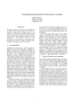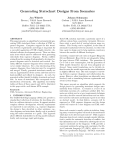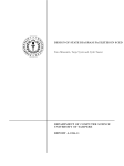
1
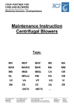
Simulation of Discrete Event Systems Unit 3 Statecharts Fall Winter 2011/2012 Univ.-Prof. Dr.-Ing. Dipl.-Wirt.-Ing. Christopher M. Schlick Chair and Institute of Industrial Engineering and Ergonomics RWTH Aachen University Bergdriesch 27 52062 Aachen phone: 0241 80 99 440 email: [email protected] © Chair and Institute of Industrial Engineering and Ergonomics, RWTH Aachen University Contents - Motivation - State Transition Diagrams (Repetition) - "Statechart Equation" - State Properties and Relations - Configurations - Transitions - Transition Connectors - Compound Transitions - Scope of Transitions © Chair and Institute of Industrial Engineering and Ergonomics, RWTH Aachen University 3-2 Motivation The previously introduced state transition diagrams (1. and 2. lecture) are often not sufficient to model dynamic system behavior efficiently because of - lacking possibilities of state refinements and hierarchies, - lacking modularization, - lacking clearness in case of many states, - lacking support of concurrent states, - lacking states with memory. These aspects apply particularly to reactive systems in mechanical engineering that usually have many states. Therefore we will present significant extensions of the well-known state transition diagrams. These extensions were invented by David Harel in 1987 and are accumulated under the technical term “statecharts” or Harel automata. © Chair and Institute of Industrial Engineering and Ergonomics, RWTH Aachen University 3-3 State transition diagrams (repetition) State machines and their representation are well-known from the lecture “Languages and Automata" (see 7. Definition). States are represented as rounded rectangles (in the lecture as circles!). The initial state is presented as a small solid filled circle, the final state as a small blank circle that contains a small filled circle. Events are represented by arrows between two states. c C e A F i l a f d b D g B k h © Chair and Institute of Industrial Engineering and Ergonomics, RWTH Aachen University 3-4 "Statechart equation" Statecharts are state transition diagrams being enhanced by hierarchical and parallel elements as well as broadcast-communication. The following “statechart equation” holds: Statechart = state transition diagram + hierarchy (depth) + orthogonality (concurrency) + broadcast-communication State transition diagrams are extended by different states that allow state grouping (by means of superstates). Orthogonal states allow modeling of concurrent processes. The broadcast-mechanism allows communication between orthogonal states. © Chair and Institute of Industrial Engineering and Ergonomics, RWTH Aachen University 3-5 Comparison of a statechart and a state transition diagram statechart state transition diagram E,F e D,G d f a f C,F F d C b b E,G a c c E e a b a d c D,F b C,G D f G e © Chair and Institute of Industrial Engineering and Ergonomics, RWTH Aachen University 3-6 Hierarchical states 1.Def.: A superstate is a state that contains another state. A substate is a state that is contained in another state. Remark: A state can be a superstate and a substate simultaneously. 2.Def.: A basic state is a state without substates. 3.Def.: A state is a root if it is not a substate of another state. © Chair and Institute of Industrial Engineering and Ergonomics, RWTH Aachen University 3-7 Example: Hierarchical states Z1 Z1.2 Z1.1 Z1.2.1 Z1.2.2 -superstates: -substates: -basic states: -root: Z1, Z1.2 Z1.1, Z1.2, Z1.2.1, Z1.2.2 Z1.1, Z1.2.1, Z1.2.2 Z1 The states of the example as a tree structure: Z1 Refinement (top-down) Z1.1 Z1.2 Z1.2.1 © Chair and Institute of Industrial Engineering and Ergonomics, RWTH Aachen University Aggregation (bottom-up) Z1.2.2 3-8 Exclusive and orthogonal states 4.Def.: Two states are exclusive if they are related to each other by “exclusive-OR". A state is an "OR"-state if its direct substates are mutually exclusive. 5.Def.: Two states are orthogonal if they are related to each other by "AND". A state is an "AND"-state if its direct substates are mutually orthogonal. Example: O is an "AND"-state with orthogonal substates O1, O2 and O3. O O1 O2 O3 A B C D Remark: A statechart consists of basic states, "OR"-states and "AND"-states. © Chair and Institute of Industrial Engineering and Ergonomics, RWTH Aachen University 3-9 Example: Exclusive and orthogonal states A O O2 O1 B1 C1 D1 C2 D2 B2 The states B1, B2 and O are mutually exclusive. The states O1 and O2 are orthogonal. A, O1, O2 are "OR"-states and O is an "AND"-state. © Chair and Institute of Industrial Engineering and Ergonomics, RWTH Aachen University 3 - 10 Default state A default state is a substate of an "OR"-state which is entered if the "OR"-state is entered. A default state is marked graphically by an arrow with a filled circle at its end. A A B B C C Both figures are equivalent. If the "OR"-state A is entered then B is entered too. © Chair and Institute of Industrial Engineering and Ergonomics, RWTH Aachen University 3 - 11 Configurations 6.Def.: A basic configuration is a complete set of mutually orthogonal basic states, i.e. the set of basic states that a system can be put in simultaneously. Remark: Sbc denotes the set of all legal basic configurations. 7.Def.: A (full) configuration is a basic configuration including the superstates of the elements of the basic configuration. Remark: Given a root state R, a configuration (relative to R) is a set of states C obeying the following rules: • C contains R. • If C contains a state A of type OR, it must contain exactly one of A's substates. • If C contains a state A of type AND, it must contain all of A's substates. • The only states in C are those that are required by the above rules. © Chair and Institute of Industrial Engineering and Ergonomics, RWTH Aachen University 3 - 12 Example: Configurations A O O2 O1 B1 C1 D1 C2 D2 B2 Basic states are B1, B2, C1, C2, D1 and D2. Sbc consists of {B1}, {B2}, {C1, D1}, {C1, D2}, {C2, D1} and {C2, D2}. The associated full configurations are {B1, A}, {B2, A}, {C1, D1, O1, O2, O, A}, {C1, D2, O1, O2, O, A}, {C2, D1, O1, O2, O, A} and {C2, D2, O1, O2, O, A}. © Chair and Institute of Industrial Engineering and Ergonomics, RWTH Aachen University 3 - 13 Transitions 8.Def.: A transition consists of a source state, a target state and a transition label. 9.Def.: A transition label is composed of an event e, a condition c and an action a. A e[ c ] / a B Remark: An event e triggers a transition. There are external and internal events. External events occur randomly outside of the statechart, internal events are generated deterministically inside of a statechart. Remark: A condition c controls a transition, i.e., the transition is only executed if the event e occurs and the condition c is true. Remark: An action a is executed if the event e occurs and the condition c is true. Remark: A transition can leave a state and return to the same state. This is called a transition to self. e[ c ] / a A © Chair and Institute of Industrial Engineering and Ergonomics, RWTH Aachen University 3 - 14 Transition Connectors (1): "AND"-Connectors A joint connector is an "AND"-connector that allows modeling the synchronization of several processes. O Event e causes substates B and C of "AND"-state O to be exited and state A to be entered. O B e A e C A fork connector is an "AND"-connector that allows modeling the splitting up into several processes. O O B A e Event e causes state A to be exited and substates B and C of the "AND"state O to be entered. C © Chair and Institute of Industrial Engineering and Ergonomics, RWTH Aachen University 3 - 15 Transition Connectors (1): “OR"-Connectors A condition connector is an "OR"-connector that differentiates between complied conditions. [b1] A e B C [b2] C Event e causes state A to be exited and state B (C) to be entered if condition b1 (b2) is true. A selection connector is an "OR"-connector that differentiates between occurred events. B A e e1 S e2 C © Chair and Institute of Industrial Engineering and Ergonomics, RWTH Aachen University Events e und e1 cause state A to be exited and state B to be entered. Events e und e2 cause state A to be exited and state C to be entered. 3 - 16 History Connector A history connector of a state Z saves the set of the most recently visited substates when leaving Z. If Z is entered again then the processing is continued with the most recently visited substate, i.e., U1 or U2. If Z is entered for the first time a default initialization is used. Z H U1 O U2 Another history connector H* saves in addition to the set of most recently visited substates the last (full) configuration. © Chair and Institute of Industrial Engineering and Ergonomics, RWTH Aachen University 3 - 17 Example: History Connector B H t4 t1 B2 B1 O t2 t3 Execution of t1 causes that - t2 is executed if the system has the most recently visited state B1 (relative to B1 and B2). - t3 is executed if the system has the most recently visited state B2 (relative to B1 and B2). - t4 and t2 is executed if the system has never visited state B. © Chair and Institute of Industrial Engineering and Ergonomics, RWTH Aachen University 3 - 18 Basic Compound Transitions A transition may consist of several transition segments. 10.Def.: Transition segments connect states and connectors. 11.Def.: A basic compound transition (CT) is a complete chain of transition segments joined by connectors that can be executed simultaneously as a single transition. Remark 1: For a set T of transition segments that lead to or emanate from an "AND"-connector every CT containing one segment of T must contain all the other segments of T. Remark 2: For sets T1 and T2 of transition segments that lead to and emanate from an "OR"connector every CT containing one segment of the union set of T1 and T2 must contain one segment of T1 and one segment of T2. © Chair and Institute of Industrial Engineering and Ergonomics, RWTH Aachen University 3 - 19 Example: Basic Compound Transitions This figure shows two basic compound transitions {e,e1} and {e,e2} with T1={e} and T2={e1,e2}. (Compare remark 2) B e1 A e S e2 © Chair and Institute of Industrial Engineering and Ergonomics, RWTH Aachen University C 3 - 20 Full Compound Transitions The execution of a basic CT does not lead necessarily to a legal configuration. Therefore a full CT is defined. 12.Def.: An initial CT is a (basic) CT whose source is a state and whose target is a state, a history connector or a termination connector. A continuation CT is a (basic) CT whose source is a default or a history connector and whose target is a state or a history connector. 13.Def.: A full CT is a combination of one initial CT and possibly several continuation CT that lead to a full basic configuration when executed. © Chair and Institute of Industrial Engineering and Ergonomics, RWTH Aachen University 3 - 21 Example: Full Compound Transitions This figure shows a full compound transition {a,b}. It is composed of the initial compound transition a and the continuation compound transition b. b B A a c C © Chair and Institute of Industrial Engineering and Ergonomics, RWTH Aachen University 3 - 22 Scope of Transitions During the execution of a transition the system might enter and leave non-basic states. The scope of a CT is the lowest state for a system without exiting and reentering. 14.Def.: The scope of a CT t is the lowest "OR"-state in the hierarchy of states that is a proper common ancestor of all the sources and targets of t, including non-basic states that are explicit sources or targets of transition arrows appearing in t. Remark: A full CT with scope S leaves a legal configuration relative to one substate of S and enters a legal configuration relative to a potential (but not essential) another substate of S. © Chair and Institute of Industrial Engineering and Ergonomics, RWTH Aachen University 3 - 23 Example: Scope of Transitions A e1 O O2 O1 B1 C1 D1 C2 D2 B2 The scope of transition e1 is A. States C1, O1, O, O2 and either D1 or D2 are exited. States O, O1, C2, O2 and D1 are entered. © Chair and Institute of Industrial Engineering and Ergonomics, RWTH Aachen University 3 - 24 References Harel, D., "Statecharts: A Visual Formalism for Complex Systems", Science Computer Programming 8 (1987), pp. 231-274. Harel, D., "Statecharts in the Making: A Personal Account", Proc. 3rd ACM SIGPLAN History of Programming Languages Conference (HOPL III), 2007. Harel, D. & Kugler, H., "The Rhapsody Semantics of Statecharts (or, On the Executable Core of the UML)", Integration of Software Specification Techniques for Applications in Engineering, (H. Ehrig et al., eds.), Lecture Notes in Computer Science, Vol. 3147, Springer-Verlag, 2004, pp. 325-354. Harel, D. & Naamad, A., "The Statemate Semantics of Statecharts", ACM Transactions on Software Engineering and Methodology, 5-4 (1996), pp. 293-333. Harel, D. & Politi, M., "Modeling Reactive Systems with Statecharts: The Statemate Approach". McGraw-Hill, 1998. Downloads: http://www.wisdom.weizmann.ac.il/~dharel/papers.html © Chair and Institute of Industrial Engineering and Ergonomics, RWTH Aachen University 3 - 25 Simulation of Discrete Event Systems Exercise to Unit 3 Statecharts Fall Winter 2011/2012 Univ.-Prof. Dr.-Ing. Dipl.-Wirt.-Ing. Christopher M. Schlick Chair and Institute of Industrial Engineering and Ergonomics RWTH Aachen University Bergdriesch 27 52062 Aachen phone: 0241 80 99 440 email: [email protected] © Chair and Institute of Industrial Engineering and Ergonomics, RWTH Aachen University 1a. Exercise Construct a corresponding state transition diagram! C A a E b a B © Chair and Institute of Industrial Engineering and Ergonomics, RWTH Aachen University b D c 3 - 27 1b. Exercise Construct a corresponding statechart! A,D c A,C A,E a a b b B,C b a a b B,D © Chair and Institute of Industrial Engineering and Ergonomics, RWTH Aachen University B,E c 3 - 28 2a. Exercise: Digital Watch Question 2a: Construct the statecharts for a digital watch (fig.) with this functionality: 1. The display has a main display and four smaller ones. 2. The watch has four control buttons. 3. The watch can display time (12 respective 24 hours mode) and date (day of month, month, day of week). 4. The watch has a light for illumination. 5. The watch has a battery with a low power indicator. (External) events are depressing of buttons. Event a denotes button a being depressed, and â denotes it being released. User manual (1) button current state function/new state b time update time c (2 seconds continuously ) time time update c time update select update content (sec., 1min, 10min,hour,month,date,day,year,12/24mode) d time/date date/time switch Time display will resume after 2 minutes in date. © Chair and Institute of Industrial Engineering and Ergonomics, RWTH Aachen University 3 - 29 Solution 2a: Overview main light display battery inserted battery removed dead power battery discharged © Chair and Institute of Industrial Engineering and Ergonomics, RWTH Aachen University 3 - 30 2b. Exercise: Digital Watch Question 2b: Enhance the watch with two independent alarms! Remark: In state alarm enter the most recently visited state, for the first time enter state „off“. User manual (2) button current state function/new state a normal (display) change display (time,alarm1,alarm2,time) d alarm setting on/off switch © Chair and Institute of Industrial Engineering and Ergonomics, RWTH Aachen University 3 - 31 Solution 2b: Extended overview (1) main alarm 1 – status light display battery inserted battery removed dead alarm 2 – status power battery discharged © Chair and Institute of Industrial Engineering and Ergonomics, RWTH Aachen University 3 - 32 2c. Exercise: Digital Watch Question 2c: Enhance the watch with a stopwatch! The stopwatch has a regular and a lap display. Zero is a special state in which the stopwatch is off but in its initial position. In state stopwatch enter the most recently visited state, for the first time enter state „zero“. Remark: If a is depressed in state alarm 2 then state stopwatch is entered. If a is depressed in state stopwatch then state time is entered. User manual (3) button current state function/new state b zero regular display & stopwatch run b stopwatch run/stop switch d lap display regular display d stopwatch run & regular display stopwatch run & lap display d stopwatch stop & regular display stopwatch to zero © Chair and Institute of Industrial Engineering and Ergonomics, RWTH Aachen University 3 - 33 3. Exercise: On Board Unit (OBU) An On Board Unit (OBU) carries out all toll collection operations during a journey on a toll route. The easiest way to log on is via the On Board Unit (OBU). Users who register with Toll Collect can order one of these On Board Units and use this to automatically log on to the toll system. Logging-on is quick and convenient with an On Board Unit. Before starting a journey, the driver simply verifies the information in the display. Everything else is handled automatically by the OBU. Using GPS satellite signals and other positioning sensors, it detects the sections of the route already driven, calculates the toll charges and transfers the data via mobile radio communication to Toll Collect for invoicing. Menu-key Arrow-keys (up, down, back, next) C-key, OK-key http://www.toll-collect.de/flash_tour/Obu/grundig/index_de.html; These keys have no functions assigned to them to date! © Chair and Institute of Industrial Engineering and Ergonomics, RWTH Aachen University 3 - 34 3a. Exercise: On Board Unit (OBU) Question 3a: Construct the statecharts for an On Board Unit (OBU) with this functionality: • • Starting the engine, starts the OBU Initial dialog contains following entries: 1. vehicle weight: maximum permitted total weight of vehicle including trailers. No toll is collected for a weight category below 12 tons. Select (<12t,>=12t) using the arrow keys (back, next), then confirm with ok. 2. number of axles: total number of axles including trailers. Select (2,3, ..,9) using the arrow keys (back, next), then confirm with ok. 3. route: a new toll charge is calculated when you select a new route. The toll charge display is reset to zero. The current toll calculation remains on the display if you do not select a new route. Select (yes, no) using the arrow keys (back, next), then confirm with ok. 4. cost center: transport company can specify cost centers for certain routes for accounting purposes. Select (00000000, …,99999999) using the arrow keys (back, next, up, down). Select the required digit with up and down keys, change to the next digit with back and next keys. Then confirm with ok. © Chair and Institute of Industrial Engineering and Ergonomics, RWTH Aachen University 3 - 35 3b. Exercise: On Board Unit (OBU) You can configure the OBU according to your requirements, Please note: The OBU menu can only be opened when the vehicle is stationary. It is not possible to operate the unit while the vehicle is in motion. Relevant keys Question 3b: Enhance the statecharts for an On Board Unit (OBU) with this functionality: 1. 2. 3. 4. 5. 6. 7. 8. 9. 10. Open the menu using the Menu key. Scroll in the submenus using the arrow keys. Open a submenu using the OK key. Cancel an entry using the C key. Select language (German, English, French and Polish) using the arrow keys (back, next), then confirm with ok. Select the weight (<12t, >=12t) using the arrow keys (back, next), then confirm with ok. Select number of axles (2,3,…9) using the arrow keys, then confirm with ok. Select new route (yes, no) using the arrow keys (back, next), then confirm with ok. Select cost center (00000000, …,99999999) using the arrow keys (back, next, up, down), then confirm with ok. Select acoustic signal tones (on, off) using the arrow keys (back, next), then confirm with ok. © Chair and Institute of Industrial Engineering and Ergonomics, RWTH Aachen University 3 - 36