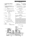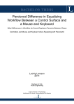
1
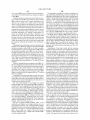
US008332757B1
(12) United States Patent
(10) Patent N0.:
(45) Date of Patent:
Davey et a1.
(54)
VISUALIZING AND ADJUSTING
PARAMETERS OF CLIPS IN A TIMELINE
2010/0278504 A1*
11/2010
11/2010 Langrnacher et a1. .
Lyons et a1. .................. .. 386/52
2010/0281379 A1*
11/2010
715/716
Meaney et a1. ............. .. 715/723
OTHER PUBLICATIONS
Sven DuWenhorst, Hamburg (DE)
“Final Cut Pro User’s Manual,” Chapter 67, Section 25 [Online]
[Retrieved on Sep. 23, 2009] Retrieved from the Internet URL: http://
(73) Assignee: Adobe Systems Incorporated, San Jose,
documentation.apple.corn/en/?nalcutpro/usermanual/index.
CA (US)
Notice:
Dec. 11, 2012
2010/0281366 A1*
(75) Inventors: Matthew Davey, Groton, MA (US);
(*)
US 8,332,757 B1
html#chapter:67%26section:25, 3 pages.
Using Adobe Premiere Pro CS4, Chapter 11, Section: “Adjusting
effects” [Online] [Retrieved on Sep. 23, 2009] Retrieved from the
Subject to any disclaimer, the term of this
patent is extended or adjusted under 35
Internet URL: http://help.adobe.corn/eniUS/PremierePro/4.0/
premiereproics4ihelp.pdf, 6 pages.
U.S.C. 154(b) by 423 days.
* cited by examiner
(21) Appl. No.: 12/565,528
(22) Filed:
(51)
(57)
ABSTRACT
Methods, systems, and apparatus, including computer pro
Int. Cl.
G06F 3/00
G06F 3/16
(52)
(58)
Primary Examiner * Ting Lee
(74) Attorney, Agent, or Firm * Fish & Richardson PC.
Sep. 23, 2009
(2006.01)
(2006.01)
grams encoded on a computer storage medium, for visualiZ
US. Cl. ....................... .. 715/716; 715/723; 715/727
ing and adjusting parameters of clips in a timeline. In one
Field of Classi?cation Search ................ .. 715/716,
aspect, a method includes generating a clip for one or more
715/727, 723
See application ?le for complete search history.
media elements having parameters, each clip being a visual
(56)
representation of an associated media element; displaying an
interface for representing each clip relative to a timeline;
displaying ?rst and second parameter lanes associated With a
References Cited
?rst clip and having associated ?rst and second parameter
lane control elements; receiving an input modifying one or
more of the ?rst and second parameter lane control elements;
and adjusting the parameters of the media element associated
With the ?rst clip according to one or more properties of the
?rst and second parameter lane control elements.
U.S. PATENT DOCUMENTS
5,404,316 A *
5,682,326 A *
2001/0040592
2003/0030661
2006/0180007
2008/0080721
A1*
A1*
A1*
A1*
4/1995
Klingler et a1. ............. .. 715/723
10/1997
Klingler et a1.
11/2001
Foreman et a1.
... ...
. . . . ..
715/202
.. ...
. . . . ..
345/723
2/ 2003 Miyauchi et a1.
4/2008
8/2006
..
McClinsey
Reid
et a1. ...................
..... ..
.. 381/104
22 Claims, 6 Drawing Sheets
ZOON
202
204
Adobe Soundbooth CS4 - Untitled Multitrack 1 *
File Edit
lip View Tasks Processes
206
Window Help
'
218
214
212
226
208a
208C
2410
208
241b
208d
241
0
208e
262
266a
2636
me
282
283
00:02:30.412
286
286a
222
220
US. Patent
Dec. 11,2012
Sheet 1 of6
US 8,332,757 B1
Display User Interface
120\
v
Receive lnput Identifying Media Element(s)
130\
v
Generate Visual Representation
for Each Media Element
"
Display Visual Representations, Each
Containing One or More Parameter Lanes
150\
v
Receive Input Editing/Adding/Removing Keyframes
in One or More of the Parameter Lanes
160\
v
Adjust Properties/Parameters of Media
Element(s) Based on Keyframes/Parameter Lanes
ll
170\
Output Media Element(s) Having Adjusted
Properties/Parameters
FIG. 1
US. Patent
Dec. 11, 2012
Sheet 5 of6
224
(
AquoVisit
l... Part1
212
arametersv
P... Part3 Part1
nensl
Part2 Part3
40D
T241
21“
US 8,332,757 B1
240
261%
eslzer
74% <1<>[>
281b
281a
260
2810
Volume
283
k
280
dd/Remove
286b
2803
234
286b
FIG. 5A
212
r
224
AquoVisi
l... P 1
arametersw
P... Part3 Part1
nensl
263
21“
n eslzer
2663
Part2 Part3
4o
261b
261a
261C
240
%
Go to Next Keyframe
260
234
Volume
%
260a
\
281a
2810
281b
212b
FIG. 5B
280
US 8,332,757 B1
1
2
VISUALIZING AND ADJUSTING
PARAMETERS OF CLIPS IN A TIMELINE
associated media element; displaying an interface for repre
senting each clip relative to a timeline; responsive to a ?rst
selection of a ?rst audio parameter, displaying in the interface
a ?rst parameter lane associated With a ?rst clip and having
BACKGROUND
associated ?rst parameter lane control elements; responsive
to a second selection of a second audio parameter, displaying
in the interface a second parameter lane While the ?rst param
The present disclosure relates to user interfaces for mixing
and editing media elements.
eter lane remains displayed, the second parameter lane being
associated With the ?rst clip and having associated second
parameter lane control elements; receiving an input modify
In general, a media element can refer to audio data, video
data, audio/video, and other data. Example sources for media
elements include audio data from a microphone or the audio
circuitry of a personal computer, audio signals from a radio
receiver (e.g., in form of an mp3 ?le), the raW audio data
ing one or more of the ?rst and second parameter lane control
stream of a compact disc drive playing an audio CD, or other
types of ?les or data streams. Audio signals encoded in the
associated With the ?rst clip according to one or more prop
elements; and adjusting the parameters of the media element
erties of the ?rst and second parameter lane control elements.
Other embodiments of this aspect include corresponding sys
tems, apparatus, and computer programs, con?gured to per
form the actions of the methods, encoded on computer stor
age devices.
These and other embodiments can each optionally include
media elements can come from different sources and have
different adjustable parameters. Examples of parameters of
audio signals include volume, intensity, signal type (e.g.,
mono, stereo), stereo Width, panorama, and phase.
Properties of audio data can be edited using a graphical
interface containing visual representations of media elements
20
one or more of the folloWing features. Each parameter lane is
ment can provide a one dimensional linear time-based area
associated With a keyframeable parameter. The keyframeable
parameter is selected from the group consisting of intensity,
Within the interface containing the visual representations of
volume, synthesizer, intensity, lead, background, rain, con
in a timeline environment. A conventional timeline environ
media elements. The timeline can be divided into one or more
tracks Where the tracks correspond to parallel subdivisions of
the timeline.
25
struction, ?ute, piano, guitar, melody, strings, solo, vocal,
oboe, percussion, bells, strings, choir, environment, clarinet,
and harmony.
Visual representations of media elements are referred to as
Adjusting the parameters of the media element further
clips. Clips can be arranged Within the timeline. Additionally,
includes adjusting the properties of one or more parameter
lane control elements in response to an input changing one or
multiple clips can be arranged Within one or more tracks of
the timeline. In general, there are no restrictions as to the
30
more of the properties of one or more parameter lane control
elements. Adjusting the properties of the one or more media
elements further includes changing one or more of the prop
erties of one or more parameter lane control elements in
response to an input changing a position of one or more
35
parameter lane control elements relative to the associated
parameter lane. The properties of one or more parameter lane
arrangement of the clips, hoWever, multiple clips Within a
single track typically do not overlap.
Clips can contain references to the source material (e.g.,
the media element) or they can contain copies of the source
material. A clip can contain multiple parameters, each of the
parameters associated With a property and/ or parameter of the
media element.
In general, a clip can contain values for particular effect
parameters in the form of one or more control points. The
control points contain the values for particular effect param
control elements further include one or more of a position
Within the parameter lane or a connection to a parameter lane
control element.
40
The one or more parameter lane control elements are icons
eters associated With a particular point in time in relation to
the timeline. Such control points are generally referred to as
having the form of one of a square, a diamond, a disc, and a
keyframes, keyframe controls, or keyframe control points. A
eters and/ or properties. The clip includes a reference to the
associated media element.
The clip includes a copy of the associated media element,
line. Each clip is arranged in a track, and the track has param
clip can contain one or more groups of one or more keyframes
that are associated With a time index relative to a timeline. A 45
and the copy has properties corresponding to the properties of
the media element. Further, adjusting the parameters of the
media element includes adjusting the parameters of the copy
of the associated media element according to the parameters
keyframe can contain a particular value for a particular effect
parameter and serves as a marker for applying those values to
the clip or track at the a speci?ed time. Therefore, each
keyframe has a type and a parameter value, and a number of
keyframes can be used to convey a time dependent series of
50
of the one or more parameter lane control elements associated
parameter value changes. A group of keyframes is part of a
clip and, therefore, is also associated With a media element.
The type of a keyframe can indicate speci?c Ways in Which
With the clip corresponding to the media element.
The method further includes displaying Within the inter
parameter value changes are processed. Examples for key
trols include one or more of a balance control, a volume
frame types are hold-keyframes and linear, BéZier, or spline
face one or more track controls. The one or more track con
55
interpolation keyframes.
control (e.g., an amplitude slider), a panorama control (e.g., a
panorama slider), a mute control, and a solo control. The
method further includes displaying Within the interface one or
SUMMARY
more track meters. The one or more track meters include one
or more of a level meter, phase scope meter, and a spectrum
This speci?cation describes technologies relating to user
interfaces for mixing and editing media elements.
In general, one innovative aspect of the subject matter
60
meter. The method further includes displaying Within the
interface one or more navigation controls. The one or more
described in this speci?cation can be embodied in methods
navigation controls include one or more of a pan control, a
Zoom control, and a current time index control.
that include the actions of receiving one or more media ele
ments including audio data, the one or more media elements
65 face one or more audio controls. The one or more audio
having associated parameters; generating a clip for each
media element, each clip being a visual representation of an
amplitude slider), a panorama control, a balance control, an
The method further includes displaying Within the inter
controls include one or more of a volume control (e.g., an
US 8,332,757 B1
3
4
equalizer, and compressor settings. The method further
can inadvertently affect source material of other clips if not
includes outputting at least one of the one or more media
properly taken care of. In accordance With the present speci
elements. The outputting further includes providing the at
?cation, such orphaned keyframes are automatically deleted
least one of the one or more media elements as a data stream
or as a data ?le.
other clips in the timeline.
or otherWise excluded from processing and cannot affect
In general, another innovative aspect of the subject matter
The details of one or more embodiments of the subject
matter described in this speci?cation are set forth in the
described in this speci?cation can be embodied in a system
including one or more processors con?gured to interact to
generate a user interface, the user interface including a time
accompanying draWings and the description beloW. Other
features, aspects, and advantages of the subject matter Will
become apparent from the description, the draWings, and the
line display including one or more clips, each clip being a
visual representation of an associated media element; a plu
claims.
rality of selectively displayable parameter lanes, each param
eter lane being associated With a ?rst clip of the one or more
BRIEF DESCRIPTION OF THE DRAWINGS
clips, the ?rst clip corresponding to a ?rst media element,
each parameter lane further being associated With a particular
FIG. 1 is a How chart shoWing an example process for
parameter of the ?rst clip; one or more parameter lane control
editing keyframes and adjusting properties of media ele
elements for each of the selectively displayable parameter
ments.
lanes; and Wherein tWo or more of the plurality of displayable
FIG. 2 is an illustration of an example user interface of a
parameter lanes are displayed concurrently; and parameters
of the ?rst media element are adjusted according to properties
keyframe parameter editor shoWing multiple parameter lanes.
20
FIG. 3 is an illustration of an example user interface of a
of the one or more parameter lane control elements in
response to input modifying at least one of the one or more
keyframe parameter editor shoWing options for displaying
multiple parameter lanes.
parameter lane control elements.
Particular embodiments of the subject matter described in
FIGS. 4A to 4D illustrate several example editing steps of
keyframe controls Within a single “Intensity” parameter lane
of an example clip.
FIGS. 5A and 5B illustrate example editing steps of key
this speci?cation can be implemented so as to realiZe one or 25
more of the folloWing advantages. As used in the present
speci?cation, a parameter lane is a group of one or more
frame controls Within a multiple parameter lanes of an
keyframes associated With a clip and a timeline. In general,
multiple parameter lanes can be displayed at the same time
example clip.
and in parallel, facilitating quick and easy editing of multiple
keyframeable parameters Without the need for sWitching
30
betWeen different modal or non-modal user interface ele
draWings indicate like elements.
ments (e.g., WindoWs, dialogs, or tabs). Furthermore, mul
tiple keyframeable parameters can be edited and adjusted in
relation to each other. For example, keyframes Within one
parameter lane can be edited With respect to keyframes in
another parameter lane. This can be done, for example, in
DETAILED DESCRIPTION
35
FIG. 1 is a How chart shoWing an example process 100 for
editing keyframes and adjusting properties of media ele
order to synchroniZe time-dependent adjustments to different
parameters or parameter lanes.
Keyframe controls can be edited, added, or removed not
only at the same time, but adjustments can be made While
FIG. 6 is a block diagram of an exemplary user system
architecture.
Like reference numbers and designations in the various
ments. For convenience, the process 100 is described With
respect to a system that performs process 100.
40
The system displays 100 a user interface. The user interface
can provide various functionality associated With an audio
editing application. Examples include opening and closing of
maintaining an overvieW of the properties of other keyframe
controls (for example number of keyframe controls, their
?les, resiZing or maximiZing the application WindoW, and
positions and/or types, as Well as other parameters). Thus,
keyframe controls can be adjusted With respect to the time
drag and drop functionality.
45
The system receives 120 input identifying media elements.
line, other tracks and/or clips, keyframe controls Within
tracks/clips, and other display or control elements (for
A user can, for example, drag and drop one or more media
example Waveform displays, audio/video streams, or video
face, e. g., into a particular region of the user interface. Alter
elements (e. g. ?les containing audio data) into the user inter
natively, ?les can be opened, e.g., through a corresponding
streams, etc.).
Keyframes can also be anchored to a clip. Thus, modi?ca
tions to the clip (for example re-arrangement to a different
time index Within the timeline) are identically applied to
50
keyframes associated With the clip (for example keyframes
Within a parameter lane associated With the clip). As a result,
clips can be re-arranged Without the need for applying the
same modi?cations to any keyframes associated With the clip.
Clips can also be trimmed. If a clip is trimmed (e.g., the
start or end of the clip is adjusted, resulting in parts of the clip
being cut out), keyframes that are associated With a time index
that falls Within the portion being trimmed along With the
55
menu structure, to retrieve ?les including media elements
from both local and remote locations. Other applications can
provide media elements as input Without interaction of a user.
The system generates 130 a visual representation for each
identi?ed media element. In some implementations, the
media ?les are identi?ed and visual representations generated
in an iterative manner. Therefore, a user can, for example,
drag and drop an audio ?le into the application WindoW. In
response to this dragging and dropping input, the system
generates a visual representation of the selected media ele
60
ment. Subsequently, the user can add more media elements,
source material are not included in further processing (e.g.,
for example, by dragging and dropping additional ?les into
such portions and keyframes are automatically ignored, for
example, in a ?nal mixdoWn). In traditional track-based key
the application WindoW. Each time, the system generates a
corresponding visual representation. In some implementa
framing systems, such keyframes are usually referred to as
“orphaned” keyframes. A problem associated With orphaned
keyframes is that the corresponding source material is no
longer present or has been moved. As a result, such keyframes
65
tions, a visual representation either contains a reference to the
media element or contains a copy of the media element.
As used in the present speci?cation, a clip is a visual
representation of a media element. A clip is associated With a
US 8,332,757 B1
5
6
media element and can include multiple parameter lanes.
Each of the parameter lanes is associated With a parameter of
the media element. Examples for parameters or properties
in a stepWise manner as de?ned by the keyframes added by
the user (e.g., according to the position of the keyframes in the
volume parameter lane).
The system outputs 170 the media element or elements in
include a volume, an intensity, a stereo Width, and a pan
accordance With the keyframes contained in the parameter
lanes associated With the corresponding clip. For example, a
orama. In general, a parameter lane can contain one or more
keyframes that are associated With a time index relative to the
associated media element. Each keyframe has a type and a
parameter value. A number of keyframes can be used to
media element corresponding to audio data can be output
using available audio circuitry of the system. Similarly, a
media element corresponding to audio/video data can be out
convey a time dependent series of parameter value changes.
Keyframes can also be recorded With the corresponding audio
content. For example, parameter lanes and the keyframes
contained therein can provide additional control (e.g., read,
put using available audio and video circuitry of the system.
Additionally, output data can be stored for later use, either
locally or remotely. The output can be stored, e.g., on com
Each clip can be displayed shoWing one or more parameter
puter readable media, for example a hard disk, optical or
magneto -optical storage medium, or ?ash memory. Addition
ally, the output data can be further edited. For example, addi
tional audio editing can be performed, for example, to modify
Write, touch) during recording of audio data.
The system displays 140 the clips in the user interface.
lanes concurrently. For example, a clip can be displayed With
other parameter or to add or remove audio effects. Addition
both an intensity parameter lane and a volume parameter lane.
ally, the output data can be combined With other tracks to form
Each parameter lane optionally includes a number of key
a mix.
frames. Alternatively, keyframes can be added to one or more 20
The steps as set forth above and as illustrated in FIG. 1 are
not restricted to a consecutive order. For example, media
parameter lanes as described beloW. Also, a clip can be shoWn
With one or more associated parameter lanes hidden from
elements can be added or removed from a set of media ele
vieW. In such a case, only the clip, optionally With individual
ments basically at any point in time. Typically, While editing
keyframes, the user Will repeatedly require media elements to
be output (e. g. played back using audio/video circuitry of the
distinguishable portions (e.g. intro, part 1, part 2, part 3, end)
is displayed. Further, visual elements (e.g., WindoWs, tabs,
25
system) or displayed in order to assess the quality of the
editing and check Whether the desired result has been
achieved. Therefore, the system can process user input that is
received, for example, in steps 120 or 150, throughout the
clips, controls, etc.) can be adjusted or modi?ed in order to
present information that is useful or necessary for user inter
action.
The system receives 150 an input editing one or more
parameter lanes. The input can be directed to one or more of 30 process.
FIG. 2 is an illustration of an example user interface 200.
the parameter lanes and can include editing, adding, or
removing keyframes. Keyframes serve to modify parameters
The user interface 200 provides for the visualization of audio
of the media elements that are associated With the clip. For
example, user input may be directed at adding a number of
keyframes to one or more parameter lanes and editing the
data Within a timeline environment. The user interface 200 is
35
provided, for example, as part of a system including a digital
audio Work station (DAW).
40
In some implementations, the user interface 200 displays
several control elements, including a menu bar 202 and drop
doWn list controls 204 and 206. The dropdoWn list controls
204 and 206 serve in the selection of multiple tracks and
single tracks respectively. Further, a slider control 216 alloWs
added or existing keyframes. Editing keyframes can include,
for example, adjusting the parameter values associated With
the keyframes or adjusting the time indexes associated With
the keyframes relative to each other and also relative to a
timeline. A given keyframe can be edited multiple times. This
for horiZontal scrolling along the timeline. The siZe and posi
Way, a user can adjust the keyframes in several parameter
lanes to his or her satisfaction, as the clip is updated With the
result of the editing to provide feedback to the user. Examples
of editing multiple parameter lanes in a single user interface
are described in greater detail beloW With respect to FIGS. 5A
tion of the slider control 216 indicate the siZe and extent of a
45
to 5B.
The system adjusts 160 the properties and/ or parameters of
each media element based on the keyframes contained in the
parameter lanes included in the clip that is associated With the
respective media element. In some implementations, the user
arranges multiple clips in relation to one another and in rela
50
current vieW provided by the interface, relative to a timeline
228 shoWn beloW slider control 216. A Zoom-out-full control
214 alloWs for adjusting the Zoom level in order to gain an
overvieW of the extend of all clips displayed in relation to the
timeline 228.
In some implementations, main controls 230 alloW for
overall adjustments of the audio parameters. Similarly, track
controls 20811 to 208e, displayed Within track 208, alloW for
track speci?c adjustment of audio parameters. For example,
tion to the timeline. For example, the user can arrange mul
track controls can include a mute control 20811, a solo control
tiple clips Within one or more tracks. Typically, multiple clips
arranged Within a single track do not overlap. Additionally,
208b, an amplitude slider control 2080, a panorama slider
multiple clips arranged Within multiple tracks, each clip being
55 one or more audio meters, for example, a mono or stereo level
control 208d. Track controls 20811 to 208e can further include
assigned a single, individual track, can overlap. In some
meter 208e.
implementations, multiple clips arranged Within a single
Generally, a clip 210 can be shoWn Within timeline 228.
track overlap and are cross-faded accordingly. Further, the
Additionally, the clip 210 can include individual parts 210a.
Further, a clip can include multiple parameter lanes, for
user can modify keyframes in multiple parameter lanes con
tained in a number of clips.
60
example parameter lanes 240, 260, 280, as shoWn Within clip
65
210. As shoWn in FIG. 2, the visual representation of a media
element (e. g., clip 210) includes a title 232 Within a title bar,
a parameters dropdoWn list control 224, and a maximiZe
control 226. Other display elements or controls may be pro
vided.
Subsequently, the system adjusts the properties and/or
parameters of the media element associated With each clip
based on the keyframes contained in the parameter lanes of
each clip. For example, a user can add three keyframes to the
“Volume” parameter lane of a clip and edit the keyframes so
as to effect a stepWise increase in volume. As a result, the
system modi?es the volume of the associated media element
The timeline also includes a linearly adjustable (e.g., hori
Zontally adjustable, as shoWn here in FIG. 2) current time
US 8,332,757 B1
7
8
index (CTI) control 212. The CTI control 212 is positioned
outside the single clip 210 and Within the displayed track 208
The interaction With and the functionality of individual
parameter lanes is described With respect to the “Intensity”
parameter lane 240 in reference to FIGS. 4A to 4D. HoWever,
it should be understood that parallel or concurrent editing
Within a number parameter lanes is generally achieved in the
at a relative time of approximately tWo minutes and 30 sec
onds (as shoWn on the loWer left hand side of the interface
200). The CTI control 212 is further shoWn as a vertical bar
212a Within the slider control 216. The interface 200 includes
a numerical value 222 of the CTI control 212. Further, the
same or a similar manner as described in reference to the
particular examples displayed in FIGS. 4A to 4D.
In some implementations, keyframe control elements have
different shapes (e.g., a quadratic shape, a rectangular shape,
interface 200 provides generic playback and recording con
trols 220.
In general, the interface 200 can display multiple param
eter lanes at the same time and in parallel, facilitating quick
a diamond shape, or a circular shape). In some implementa
tions, the shape of a keyframe control element indicates spe
ci?c properties of the keyframe control element and/or the
corresponding parameter lane. In the example shoWn in FIG.
2, keyframe control element 24611 has a quadratic shape and
keyframe control element 26611 has a diamond shape.
and easy editing of multiple keyframeable parameters With
out the need for sWitching betWeen different modal or non
modal user interface elements (e.g., WindoWs, dialogs, and
tabs). The display size of individual parameter lanes 240, 260,
280 can be adjusted Within the limits of the display area of
In some implementations, a quadratic shape may be asso
ciated With a hold keyframe (e.g., holding a constant value
level betWeen keyframes) and a diamond shape may be asso
interface 200 and/or clip 210.
In some implementations, interface 200 displays multiple
parameter lanes concurrently so as to facilitate editing of
keyframeable parameters in multiple parameter lanes at the
20
ciated With a linear interpolation (e. g., linearly interpolating
value levels betWeen keyframes). A hold-keyframe may be
same time and in relation to each other. Editing of keyframe
associated With keeping a parameter value at a constant level
able parameters can be achieved for example using keyframe
used for different audio sources in a mixer setting (e.g.,
from the time index associated With the keyframe control and
the time index associated With the subsequent keyframe con
trol or the end of the associated clip (e. g., a step function). A
linear interpolation keyframe control may be associated With
adjusting a parameter value linearly betWeen the time index
associated With the keyframe control and the time index asso
strings, piano, or vocals). In such cases, the media elements
ciated With the subsequent keyframe control.
controls as described further beloW. Each of the multiple
parameter lanes is typically associated With a speci?c param
eter type. Parameter types can include, for example volume or
25
intensity. Other examples include different input channels as
can include different channels containing audio data that can
be edited separately from each other. In some implementa
30
tions, input channel type parameter lanes and audio properties
(eg volume, intensity, etc.) parameter lanes are distin
guished from one another.
Further, keyframe controls can be edited, added, or
removed not only at the same time, but adjustments can be
made While maintaining an overvieW of the properties of
other keyframe controls (e.g., the number of keyframe con
trols, their positions, and their types). Thus, keyframe con
trols can be adjusted With respect to the timeline, With respect
to other tracks and/or clips, With respect to keyframe controls
Within tracks/clips, and/or With respect to other display or
control elements (e.g., Waveform displays, audio/video
In some implementations, interface 200 displays param
eter lanes Within clip 210 as shoWn in FIG. 2. Here, each
parameter lane has further display elements. For example,
“Intensity” parameter lane 240 has a title element 242, one or
more keyframe control elements 246, and a display element
243. Further, parameter lane 240 has keyframe navigation
35
40
controls 241, including three separate controls, namely “pre
vious” keyframe control 241a, “add/remove” keyframe con
trol 241b, and “next” keyframe control 2410. Other lanes may
have the same (for example title elements 262 and 282, dis
play elements 263 and 283, keyframe navigation controls 261
and 281, keyframe control elements 266 and 286, or other
elements. The size of the clip can be adjusted, for example
With the maximize control 226, or any of the zoom controls
streams, or video streams).
(e.g., zoom-out-full control 214). Adjusting the size of slider
Examples for adjustments that can require coordinated
adjustments in several parameter lanes can include linearly
decreasing the overall volume of a clip, While increasing the
volume of individual components. In this Way, for example,
single or multiple components in a clip (e. g., strings, piano, or
control 216 (e.g., by adjusting either or both of controls 216a
45
200, in Which multiple parameter lanes 240, 260, 280 are
shoWn Within clip 210. In this example, parameters drop
vocals) can be emphasized in relation to the remaining com
ponents of the clip, While maintaining the perceived loudness
of the overall clip (i.e. keeping the clip at subjectively the
50
doWn list control 224 is shoWn in an activated state, display
ing generic options 224a, 224b, 224], and 224g, and param
eter options 2240, 224d, and 224e. In some implementations,
there can be multiple parameter options, including one or
same volume level).
In some implementations, keyframeable parameters are
more of: Volume, Intensity, Lead, Background, Background
anchored relative to the clip, instead of being anchored rela
tive to the timeline or a track. This facilitates clip-oriented
and 2161)) also changes the size of all clips displayed Within
interface 200.
FIG. 3 is another illustration of an example user interface
55
management of keyframeable parameters. For example, clips
1, Background 2, Synthesizer, Synth l, Synth 2, Rain, Con
struction, Flute, Piano, Piano 1, Piano 2, Guitar, Melody,
can be edited, moved, adjusted or otherWise re-arranged
Strings, Solo, Vocal, Oboe, Percussion, Bells, Strings, Choir,
Within one or more tracks, Without the requiring subsequent
Environment, Clarinet, and Harmony. Other parameter
modi?cation of keyframeable parameters (e.g., keyframe
controls). In other Words, if a clip is re-arranged Within the
timeline, all keyframe controls contained in the clip (or con
tained Within parameter lanes that are contained in the clip)
are re-arranged accordingly. Thus, the keyframe controls are
not modi?ed in relation to the clip, but in relation to the
timeline or track, therefore not requiring any adjustments or
modi?cation to the keyframe controls due to the re-arranging
of the clip.
60
options can be provided.
In the example shoWn in FIG. 3, three parameter options
are selected, namely Intensity 224c, Synthesizer 224d, and
Volume 224e. Upon selection of any of these parameter
65
options, the respective option is checked/unchecked and the
display of corresponding parameter lane beloW clip 210 is
toggled accordingly. Each parameter lane that is displayed
can be used to edit/add/remove keyframe controls that serve
to adjust parameters of the media element associated With the
US 8,332,757 B1
10
clip 210. For example, if parameter lane 280 is selected for
FIG. 4B illustrates an example modi?cation of the position
of the keyframe control 24611. A user may select keyframe
control 24611 by positioning the cursor 234 over the keyframe
display (e.g., the corresponding option 224e is checked in
parameter dropdoWn list 224), the user can adjust the volume
of the media element associated With clip 210 by editing/
adding/removing keyframe controls 286a, 286b, etc. as dis
control 246a and clicking an associated button on a suitable
input device (eg a mouse, trackball, etc.). In some imple
mentations, the visual appearance of the keyframe control
24611 is changed to visually indicate a status change (e.g.
played in parameter lane 280 (see FIG. 2).
In some implementations, the display of all parameter
active/inactive or selected/unselected) to the user. For
lanes (e.g. lanes 2240, 224d, 224e) is toggled With generic
options 224a and 224b, switching the display of all parameter
example, as shoWn in FIG. 4B, the keyframe control 24611 is
highlighted in a particular color and a gloW-type visual effect
lanes respectively on or off.
is applied. Other visual effects may be provided, for example
Further, in some implementations, other options are avail
to provide visual feedback to the user. In some implementa
able, for example, options switching to basic editing 224], or
sWitching to keyframe editing 224g. In general, the number of
tions, a focus is assigned to any single parameter lane (e.g.,
any of parameter lanes 240, 260, 280 in this example). Visual
feedback (for example a different colored background, frame,
options and/ or parameter lanes is not limited in any particular
Way, other than, for example by the amount of available
or title) can indicate that the focus is assigned to a particular
parameter lane. For example, parameter lane 240 can contain
memory, processing poWer, or addressable display area.
FIGS. 4A to 4D illustrate several editing steps Within a
parameter lane, e.g., parameter lane 240 shoWn in FIG. 2. The
shape of cursor 234 may change depending on the position
an additional frame or a frame having a different color, in
order to indicate that the focus is assigned to parameter lane
20
Within the interface 200. For example, the cursor 234 may
change to a cross-hair shape When positioned Within a param
240.
In some implementations, When the focus is assigned to a
parameter lane, user input (for example key strokes) are pro
eter lane (e.g., parameter lane 240). Further, the shape of
cessed With a context associated With the parameter lane
cursor 234 can change upon positioning of the cursor over
having the focus. In some implementations, pressing one of
the left and right arroW keys results in the CTI control 212
being moved left or right, respectively. In some implementa
tions, the movement of the CTI control 212 in response to
certain display elements or controls (e.g., keyframe control
25
246a).
FIGS. 4A to 4D shoW an enlarged vieW of clip 210 Within
user interface 200. For illustration purposes, only parameter
lane 240 is shoWn Within clip 210. In this example, “Inten
sity” parameter lane 240 is shoWn enlarged as compared to
clip 210. In this example, interface 200 does not display other
parameter lanes. Generally, the size of any parameter lane or
the clip 210 can be adjusted in order to facilitate adequate
display of keyframe controls or other elements, and/or in
keyboard input can be restricted to existing keyframes. For
example, pressing one of the left and right arroW keys can
30
alloW the user to move the CTI control 212 the time index
associated With the previous/next keyframe control located to
the left or right from the current position of the CTI control
212. In some implementations, upon selection of a keyframe
control, the user can move the keyframe control horizontally
order to facilitate interaction With one or more controls or 35
and/or vertically by pressing one of the left/right/up/doWn
elements at a greater or reduced level of detail.
arroW keys While holding doWn a modi?er key (e.g., the ALT
modi?er key). Other modi?er keys can be associated With
other or additional functionality, e.g., adding or removing
keyframe controls With the shift modi?er key or the CTRL
In the example shoWn in FIG. 4A, the “Intensity” level of
clip 210 is constant for the entire duration of clip 210. Here,
a single horizontal line control 246 indicates the level visu
are positioned along the line 246, located at different time
modi?er key.
By dragging the keyframe control 246a vertically doWn
indexes. In this example, keyframe controls 246a, 246b, and
Wards, the associated parameter value (here “Intensity”) can
2460 are of the type hold-keyframe. Thus, a parameter value,
be decreased. In some implementations, the current param
ally, Whereas three keyframe controls 246a, 246b, and 2460
40
eter value is displayed concurrently in a tool-tip style display
here the level of intensity, is maintained at a constant level
betWeen consecutive keyframes and is adjusted at each key
45
element (e.g., element 24711 as shoWn in FIG. 4B). In this
frame to the associated parameter value. The parameter lane
example, not only is the keyframe control 246a dragged ver
240 shoWs that all three keyframe controls 246a, 246b, and
tically doWnWards, but also horizontally to the left, thereby
adjusting the time index associated With the keyframe control
2460 are positioned at the same vertical position. Thus, the
level of intensity is constant over the entire duration of the
parameter lane 240 and clip 210.
Parameter values can be adjusted in multiple Ways. For
example, the position of existing keyframe controls can be
50
moved, linear element 246 is adjusted accordingly, depend
55
ing on the type of the keyframe control 24611. The linear
element 246 associated With a hold-keyframe (e.g., keyframe
control 246a) is moved vertically according to the keyframe
control 24611. The sub sequent keyframe control 2461) remains
60
along the vertical position of keyframe control 246a up to the
time index associated With keyframe control 2461). At this
time index, the line element 246 has a vertical shape, indicat
ing that the line element 246 continues at the vertical position
adjusted. Keyframe controls can be added to or removed from
a parameter lane.
Adjusting parameter values by adjusting existing keyframe
controls can be achieved by adjusting the position of a key
frame control. The horizontal position of a keyframe control
is associated With the time index relative to the clip, i.e. the
beginning and duration of the clip. Moving a keyframe con
trol horizontally alloWs for the adjustment of the time index
at its position, so that line element 246 continues horizontally
of keyframe control 2461) from the time index on that is
associated With the keyframe control. In case of a hold-key
frame this is the time index at Which the corresponding
parameter value is coming into effect. Moving a keyframe
control vertically alloWs for adjusting the parameter value
itself. For example, moving a keyframe control up increases
the associated parameter value and moving the keyframe
control doWn decreases the associated parameter value.
24611 to an earlier point in time.
In some implementations, as the keyframe control 24611 is
associated With keyframe control 2461).
In some implementations, interface 200 keeps displaying
the previous position of a keyframe control that is being
65
adjusted While the adjustment is taking place. In FIG. 4B,
interface 200 keeps displaying the previous position 24911 of
keyframe control 24611. The previous position 249a can be
US 8,332,757 B1
11
12
displayed visually different from the appearance of keyframe
controls are linearly interpolated. As shoWn in parameter
lanes 260 and 280 in FIG. 3, parameter values are interpolated
control 24611, for example, using a different opacity. In a
similar manner, interface 200 may keep displaying the previ
ous shape, position, or form 249 of linear element 246 during
the time keyframe control 24611 is being modi?ed.
FIG. 4C illustrates selected parameter lane 240, containing
selected keyframe control 246a and unselected keyframe
betWeen keyframe controls (for example keyframe controls
266a and 266b, or keyframe controls 286a and 28619).
In some implementations, other time-dependent adjust
ments of parameter values are provided, for example, based
on parametric curves (for example BeZier-curves) or linear
controls 24619 and 2460, as Well as line element 246, after the
and non-linear equations.
adjustment of the position of keyframe control 24611 as
In some implementations, keyframe controls are added and
removed in response to user input selecting the “add/remove”
described With reference to FIG. 4B. In some implementa
tions, selected elements (for example keyframe control 246a
keyframe control 2411) (see also FIG. 2) in combination With
and/or parameter lane 240) remain selected until user input
the position of the CTI control 212 and the parameter lane
currently having the focus. If the CTI control 212 is posi
selecting a different element or control is received.
FIG. 4D illustrates an example modi?cation of the position
of the keyframe control 2460, similar to the example modi?
cation of the position of the keyframe control 24611 as shoWn
in FIG. 4B. Here, dragging the keyframe control 2460 verti
cally upWards, increases the associated parameter value. In
this example, the current parameter value is displayed con
currently in a tool-tip style display element 2470. Further,
dragging keyframe control element 246c horiZontally to the
right adjusts the time index associated With the keyframe
tioned at the time index associated With a keyframe control
Within the parameter lane having the focus, then this speci?c
keyframe control can be removed in response to user input
selecting the “add/remove” keyframe control 2411). A user
can, for example, position the CIT control 212 on and move
20
frame 241c controls.
control 2460 to a later point in time.
Within the parameter lane having the focus, the CTI control
Accordingly, movement of keyframe control 2460 adjusts
line element 246. Generally, line element 246 indicates the
25
intensity level (the parameter value associated With parameter
lane 240) of the clip from the beginning of the clip (for
control 212 is moved to the time index associated With a
index of the ?rst keyframe control, namely keyframe control
previous or earlier keyframe control (i.e., a keyframe control
30
35
40
single parameter lane having the focus.
In some implementations, other controls are provided for
pop-up menus or keyboard short-cuts.
45
FIGS. 5A and 5B illustrate example editing of keyframe
controls Within multiple parameter lanes of an example clip.
FIG. 5A shoWs an enlarged vieW of clip 210 Within user
interface 200. In this example, parameter lanes 240, 260, and
280 are shoWn concurrently Within clip 210.
50
There are several possibilities to add/remove keyframe
controls Within a parameter lane. One technique includes
keyframe navigation controls, for example, keyframe naviga
control (i.e., the keyframe control associated With the highest
time index) and the end of the clip, the intensity level is kept
tion controls 281 (i.e., keyframe navigation controls 281a,
constant at the value associated With the keyframe control
having the highest time index.
As indicated above, different parameter lanes can provide
In some implementations, clip based controls (not shoWn)
corresponding to controls 241a, 241b, and 2410 are provided,
editing/adding/removing keyframe controls, for example
With keyframe control 2460. Similarly, additional keyframe
controls could be created in parameter lane 240. Finally,
betWeen the time index associated With the last keyframe
CTI control 212 may be positioned at the beginning or end of
the clip, or at other time indexes.
Which alloW for overall movement betWeen keyframe con
trols contained in different parameter lanes, not just Within a
246b, the intensity level is maintained at a constant value
associated With keyframe control 246a.
At the time index associated With keyframe control 246b,
the intensity level is adjusted to the value associated With
keyframe control 2461). Accordingly, betWeen the time index
associated With keyframe control 2461) and the time index
associated With keyframe control 2460, the intensity level is
kept constant at the value associated With keyframe control
2461). At the time index associated With keyframe control
2460, the intensity level is adjusted to the value associated
associated With a loWer time index) upon activation of control
24111. If no previous or next (i.e. earlier or later) keyframe
control is present in the parameter lane having the focus, the
With the ?rst keyframe (i.e., the keyframe control associated
With the loWest time index) in a parameter lane for the time
prior to the time index associated With the ?rst keyframe.
BetWeen the time index associated With keyframe control
246a and the time index associated With keyframe control
212 is moved to the time index associated With a subsequent
or later keyframe control (i.e., a keyframe control associated
With a higher time index) upon activation of control 2410.
LikeWise, Within the parameter lane having the focus, the CTI
example, time index 00:00:00 Within the clip), up to the time
24611, Where the intensity level is adjusted to the value asso
ciated With keyframe control 24611. In some implementations,
the parameter value is kept constant at the level associated
the CTI control 212 betWeen existing keyframe controls by
activating the “previous” keyframe 241a and “next” key
55
different functionality associated With time-dependent
adjustment of parameter values. For example a hold-key
281b, and 2810). The process is described With reference to
FIG. 5A and in reference to parameter lane 280. It should be
understood that this process is applicable to other parameter
lanes (e.g., parameter lanes 240 and 260 in combination With
keyframe navigation controls 241 and 261 respectively).
frame may be associated With keeping a parameter value at a
The user can position CTI control 212 at a certain time
constant level from the time index associated With the key
frame control and the time index associated With the subse
quent keyframe control or the end of the associated clip, as
index, also denoted by vertical line 212b, namely the time
60
index Where a keyframe control is to be added/removed. In
response to the user selecting keyframe navigation control
described above in reference to FIGS. 4A to 4D.
281b, the “add/remove keyframe” control, keyframe control
LikeWise, a linear interpolation keyframe control may be
associated With adjusting a parameter value linearly betWeen
the time index associated With the keyframe control and the
time index associated With the sub sequent keyframe control.
Here, the parameter values betWeen consecutive keyframe
2861) is created, as shoWn in FIG. 5A. Accordingly, if key
frame control 286b had already been existing at the time
index denoted by CTI control 212, a selection of keyframe
navigation control 2811) Would have resulted in keyframe
2861) being removed from parameter lane 280. A tool-tip
65
US 8,332,757 B1
13
14
(e.g., tool-tip 280a) may be displayed upon positioning of
The operating system 616 can be multi-user, multiprocess
ing, multitasking, multithreading, real-time and the like. The
operating system 616 performs basic tasks, including but not
cursor 234 over a control element (e.g., keyframe navigation
control 2811)).
limited to: recogniZing input from input devices 610; sending
Alternatively, the user can position cursor 234 over a por
output to display devices 604; keeping track of ?les and
directories on computer-readable mediums 612 (e.g.,
memory or a storage device); controlling peripheral devices
(e.g., disk drives, printers, etc.); and managing tra?ic on the
tion of linear element 286. Upon selection of linear element
286, a keyframe control can be created. Depending on the
selection (e.g., activation of a control button of a pointing
device), a pop-up menu may be displayed, providing several
one or more buses 614. The netWork communications module
options, including adding and removing keyframe controls.
618 includes various components for establishing and main
Other Ways to add/remove keyframes may be provided. For
taining netWork connections (e. g., softWare for implementing
communication protocols, such as TCP/IP, HTTP, Ethernet,
example, the user may use a pointing device to point to an area
betWeen tWo keyframes Within a parameter lane. Activating
etc.). The broWser 620 enables the user to search a netWork
associated input means (e.g., clicking a mouse button or a
button on a trackball device) then adds a keyframe to the
parameter lane. The system then integrates the neWly added
keyframe control into the parameter lane by adjusting the
parameters of the keyframe in accordance With its position
Within the parameter lane and by providing corresponding
line elements connecting the keyframe With existing key
(e.g., Internet) for information (e.g., digital media items).
The digital audio Workstation 622 provides various soft
Ware components for performing the various functions for
receiving media elements, generating clips, displaying the
user interface including display and control elements, receiv
ing user input, adjusting parameters of the media elements,
20
frames.
Navigating betWeen keyframe controls is described With
reference to FIG. 5B and in reference to parameter lane 280.
Keyframe navigation controls 281 can be used to navigate
betWeen keyframes contained in parameter lane 280. Select
25
ing keyframe navigation control 281a (i.e. the “previous”
keyframe navigation control) serves to position the CTI con
trol 212 at the time index Which the keyframe located to the
left from the current position of CTI control 212 is associated
With. If there is no keyframe control positioned left of CTI
30
control 212, keyframe navigation control 281a cannot be
selected and/or the current position of CTI control 212 is not
35
cal, or electromagnetic signal, that is generated to encode
information for transmission to suitable receiver apparatus
right of CTI control 212, keyframe navigation control 281a
for execution by a data processing apparatus. A computer
40
storage medium can be, or be included in, a computer-read
able storage device, a computer-readable storage substrate, a
An example for a keyframe navigation control that cannot
be selected is shoWn in FIG. 5B. Here, keyframe navigation
control 261a, associated With parameter lane 260, cannot be
random or serial access memory array or device, or a combi
nation of one or more of them. Moreover, While a computer
storage medium is not a propagated signal, a computer stor
45
age medium can be a source or destination of computer pro
gram instructions encoded in an arti?cially-generated propa
gated signal. The computer storage medium can also be, or be
architecture 600. The system architecture 600 is capable of
hosting a audio processing application that can electronically
receive one or more media elements and display and edit
gram instructions can be encoded on an arti?cially-generated
propagated signal, e.g., a machine-generated electrical, opti
CTI control 212 at the time index that the keyframe located to
the right from the current position of CTI control 212 is
associated With. If there is no keyframe control positioned
selected. As shoWn, the visual appearance of an inactive con
trol element may indicate this state.
FIG. 6 is a block diagram of an exemplary user system
tion and their structural equivalents, or in combinations of one
or more of them. Embodiments of the subject matter
described in this speci?cation can be implemented as one or
more computer programs, i.e., one or more modules of com
Likewise, selecting keyframe navigation control 2810 (i.e.
cannot be selected and/ or the current position of CTI control
212 is not modi?ed.
1-5B, including interaction With the user interface, clips,
parameter lanes and the editing of keyframes and other con
trol elements.
Embodiments of the subject matter and the operations
described in this speci?cation can be implemented in digital
electronic circuitry, or in computer softWare, ?rmWare, or
hardWare, including the structures disclosed in this speci?ca
puter program instructions, encoded on computer storage
medium for execution by, or to control the operation of, data
processing apparatus. Alternatively or in addition, the pro
modi?ed.
the “next” keyframe navigation control) serves to position the
and providing output, as described With respect to FIGS.
included in, one or more separate physical components or
50
media (e.g., multiple CDs, disks, or other storage devices).
The operations described in this speci?cation canbe imple
visual representations thereof. The architecture 600 includes
mented as operations performed by a data processing appa
one or more processors 602 (e.g., IBM PoWerPC, Intel Pen
ratus on data stored on one or more computer-readable stor
tium 4, etc.), one or more display devices 1404 (e.g., CRT,
age devices or received from other sources.
LCD), graphics processing units 606 (e.g., NVIDIA GeForce,
etc.), a netWork interface 608 (e.g., Ethernet, FireWire, USB,
etc.), input devices 610 (e.g., keyboard, mouse, etc.), and one
55
or more computer-readable mediums 612. These components
exchange communications and data via one or more buses
sor, a computer, a system on a chip, or multiple ones, or
614 (e.g., EISA, PCI, PCI Express, etc.).
The term “computer-readable medium” refers to any
medium that participates in providing instructions to a pro
cessor 602 for execution. The computer-readable medium
612 further includes an operating system 616 (e.g., Mac OS®,
WindoWs®, Linux, etc.), a netWork communication module
618, a broWser 620 (e.g., Safari®, Microsoft® Internet
The term “data processing apparatus” encompasses all
kinds of apparatus, devices, and machines for processing
data, including by Way of example a programmable proces
60
combinations, of the foregoing The apparatus can include
special purpose logic circuitry, e.g., an FPGA (?eld program
mable gate array) or an ASIC (application-speci?c integrated
circuit). The apparatus can also include, in addition to hard
Ware, code that creates an execution environment for the
65
computer program in question, e.g., code that constitutes
processor ?rmWare, a protocol stack, a database management
system, an operating system, a cross-platform runtime envi
Explorer, Netscape®, etc.), a digital audio Workstation 622,
ronment, a virtual machine, or a combination of one or more
and other applications 624.
of them. The apparatus and execution environment can real
US 8,332,757 B1
15
16
iZe various different computing model infrastructures, such
as Web services, distributed computing and grid computing
feedback; and input from the user can be received in any form,
including acoustic, speech, or tactile input. In addition, a
infrastructures.
A computer program (also knoWn as a program, software,
softWare application, script, or code) can be Written in any
and receiving documents from a device that is used by the
user; for example, by sending Web pages to a Web broWser on
form of programming language, including compiled or inter
preted languages, declarative or procedural languages, and it
Web broWser.
computer can interact With a user by sending documents to
a user’ s client device in response to requests received from the
Embodiments of the subject matter described in this speci
?cation can be implemented in a computing system that
can be deployed in any form, including as a stand-alone
program or as a module, component, subroutine, object, or
other unit suitable for use in a computing environment. A
computer program may, but need not, correspond to a ?le in a
?le system. A program can be stored in a portion of a ?le that
holds other programs or data (e.g., one or more scripts stored
includes a back-end component, e. g., as a data server, or that
includes a middleWare component, e.g., an application server,
or that includes a front-end component, e.g., a client com
puter having a graphical user interface or a Web broWser
through Which a user can interact With an implementation of
the subject matter described in this speci?cation, or any com
bination of one or more such back-end, middleWare, or front
in a markup language document), in a single ?le dedicated to
the program in question, or in multiple coordinated ?les (e.g.,
?les that store one or more modules, sub-programs, or por
end components. The components of the system can be inter
connected by any form or medium of digital data
communication, e.g., a communication netWork. Examples
tions of code). A computer program can be deployed to be
executed on one computer or on multiple computers that are
located at one site or distributed across multiple sites and
interconnected by a communication netWork.
20
The processes and logic ?oWs described in this speci?ca
(e.g., the Internet), and peer-to-peer netWorks (e.g., ad hoc
tion can be performed by one or more programmable proces
sors executing one or more computer programs to perform
actions by operating on input data and generating output. The
processes and logic ?oWs can also be performed by, and
apparatus can also be implemented as, special purpose logic
circuitry, e.g., an FPGA (?eld programmable gate array) or an
peer-to-peer netWorks).
25
The computing system can include clients and servers. A
client and server are generally remote from each other and
typically interact through a communication netWork. The
relationship of client and server arises by virtue of computer
programs running on the respective computers and having a
ASIC (application-speci?c integrated circuit).
Processors suitable for the execution of a computer pro
gram include, by Way of example, both general and special
of communication netWorks include a local area netWork
(“LAN”) and a Wide area netWork (“WAN”), an inter-netWork
30
client-server relationship to each other. In some embodi
ments, a server transmits data (e.g., an HTML page) to a client
device (e. g., for purposes of displaying data to and receiving
user input from a user interacting With the client device). Data
generated at the client device (e.g., a result of the user inter
purpose microprocessors, and any one or more processors of
any kind of digital computer. Generally, a processor Will
receive instructions and data from a read-only memory or a
random access memory or both. The essential elements of a
action) can be received from the client device at the server.
While this speci?cation contains many speci?c implemen
computer are a processor for performing actions in accor 35
dance With instructions and one or more memory devices for
tation details, these should not be construed as limitations on
storing instructions and data. Generally, a computer Will also
include, or be operatively coupled to receive data from or
the scope of any inventions or of What may be claimed, but
rather as descriptions of features speci?c to particular
embodiments of particular inventions. Certain features that
transfer data to, or both, one or more mass storage devices for
storing data, e.g., magnetic, magneto-optical disks, or optical
40
disks. HoWever, a computer need not have such devices.
Moreover, a computer can be embedded in another device,
e.g., a mobile telephone, a personal digital assistant (PDA), a
mobile audio or video player, a game console, a Global Posi
tioning System (GPS) receiver, or a portable storage device
45
implemented in multiple embodiments separately or in any
suitable subcombination. Moreover, although features may
be described above as acting in certain combinations and even
(e. g., a universal serial bus (U SB) ?ash drive), to name just a
feW. Devices suitable for storing computer program instruc
initially claimed as such, one or more features from a claimed
combination can in some cases be excised from the combi
tions and data include all forms of non-volatile memory,
media and memory devices, including by Way of example
semiconductor memory devices, e.g., EPROM, EEPROM,
and ?ash memory devices; magnetic disks, e.g., internal hard
are described in this speci?cation in the context of separate
embodiments can also be implemented in combination in a
single embodiment. Conversely, various features that are
described in the context of a single embodiment can also be
nation, and the claimed combination may be directed to a
50
subcombination or variation of a subcombination.
Similarly, While operations are depicted in the draWings in
disks or removable disks; magneto-optical disks; and CD
a particular order, this should not be understood as requiring
ROM and DVD-ROM disks. The processor and the memory
that such operations be performed in the particular order
can be supplemented by, or incorporated in, special purpose
logic circuitry.
55
shoWn or in sequential order, or that all illustrated operations
be performed, to achieve desirable results. In certain circum
subject matter described in this speci?cation can be imple
stances, multitasking and parallel processing may be advan
tageous. Moreover, the separation of various system compo
mented on a computer having a display device, e.g., a CRT
nents in the embodiments described above should not be
To provide for interaction With a user, embodiments of the
(cathode ray tube) or LCD (liquid crystal display) monitor,
for displaying information to the user and a keyboard and a
pointing device, e. g., a mouse or a trackball, by Which the user
understood as requiring such separation in all embodiments,
60
single softWare product or packaged into multiple softWare
can provide input to the computer. The display device can be
of a kind having integrated input means or pointing device,
products.
Thus, particular embodiments of the subject matter have
e.g., a touch screen. Other kinds of devices can be used to
provide for interaction With a user as Well; for example,
feedback provided to the user can be any form of sensory
feedback, e.g., visual feedback, auditory feedback, or tactile
and it should be understood that the described program com
ponents and systems can generally be integrated together in a
65
been described. Other embodiments are Within the scope of
the folloWing claims. In some cases, the actions recited in the
claims can be performed in a different order and still achieve
US 8,332,757 B1
17
18
desirable results. In addition, the processes depicted in the
8. The method of claim 1, Wherein the ?rst shape and the
second shape are selected from the group consisting of a
quadratic shape, a diamond, a rectangular shape and a circular
accompanying ?gures do not necessarily require the particu
lar order shoWn, or sequential order, to achieve desirable
shape.
results. In certain implementations, multitasking and parallel
processing may be advantageous.
9. A computer program product, encoded on a non-transi
What is claimed is:
tory computer readable storage medium, operable to cause a
1. A computer-implemented method, comprising:
data processing apparatus to perform operations comprising:
receiving one or more media elements including audio
data, the one or more media elements having associated
receiving one or more media elements including audio
data, the one or more media elements having associated
parameters;
parameters;
generating a clip for each media element, each clip being a
visual representation of an associated media element;
displaying an interface for representing each clip relative to
generating a clip for each media element, each clip being a
visual representation of an associated media element;
displaying an interface for representing each clip relative to
a timeline;
responsive to a ?rst selection of a ?rst audio parameter,
a timeline;
responsive to a ?rst selection of a ?rst audio parameter,
displaying in the interface a ?rst parameter lane associ
ated With a ?rst clip and having associated ?rst param
eter lane control elements, Wherein a particular ?rst
parameter lane control element is associated With a ?rst
shape and Wherein the ?rst shape indicates a property of
displaying in the interface a ?rst parameter lane associ
ated With a ?rst clip and having associated ?rst param
eter lane control elements, Wherein a particular ?rst
parameter lane control element is associated With a ?rst
shape and Wherein the ?rst shape indicates a property of
20
the particular ?rst parameter lane control element;
the particular ?rst parameter lane control element;
responsive to a second selection of a second audio param
eter, displaying in the interface a second parameter lane
While the ?rst parameter lane remains displayed, the
second parameter lane being associated With the ?rst
clip and having associated second parameter lane con
trol elements, Wherein a particular second parameter
responsive to a second selection of a second audio param
25
lane control element is associated With a second shape,
Wherein the second shape indicates a property of the
particular second parameter lane control element,
eter, displaying in the interface a second parameter lane
While the ?rst parameter lane remains displayed, the
second parameter lane being associated With the ?rst
clip and having associated second parameter lane con
trol elements, Wherein a particular second parameter
lane control element is associated With a second shape,
Wherein the second shape indicates a property of the
30
particular second parameter lane control element,
Wherein the ?rst and second shapes are different and the
Wherein the ?rst and second shapes are different and the
respective indicated properties are different, and
respective indicated properties are different, and
Wherein the ?rst shape indicates a hold keyframe
betWeen parameter lane control elements and the second
shape indicates a linear interpolation betWeen parameter
lane control elements;
Wherein the ?rst shape indicates a hold keyframe
betWeen parameter lane control elements and the second
shape indicates a linear interpolation betWeen parameter
lane control elements;
35
receiving an input modifying one or more of the ?rst and
receiving an input modifying one or more of the ?rst and
second parameter lane control elements; and
adjusting the parameters of the media element associated
second parameter lane control elements; and
adjusting the parameters of the media element associated
With the ?rst clip according to one or more properties of
the ?rst and second parameter lane control elements.
2. The method of claim 1, Where each parameter lane is
associated With a keyframeable parameter.
3. The method of claim 2, Where the keyframeable param
eter is selected from the group consisting of intensity, volume,
40
10. The computer program product of claim 9, Where each
parameter lane is associated With a keyframeable parameter.
11. The computer program product of claim 10, Where the
45
synthesiZer, lead, background, rain, construction, ?ute, piano,
guitar, melody, strings, solo, vocal, oboe, percussion, bells,
strings, choir, environment, clarinet, and harmony.
4. The method of claim 1, Where adjusting the parameters
of the media element further comprises:
struction, ?ute, piano, guitar, melody, strings, solo, vocal,
oboe, percussion, bells, strings, choir, environment, clarinet,
and harmony.
50
prises:
adjusting the properties of one or more parameter lane
control elements in response to an input changing one or
control elements.
55
13. The computer program product of claim 12, further
operable to cause data processing apparatus to perform opera
parameter lane control elements in response to an input
changing a position of one or more parameter lane con
control, a linear interpolation control, a navigation control,
and an edit control.
more of the properties of one or more parameter lane
control elements.
changing one or more of the properties of one or more
more parameter lane control elements further comprise one or
more of a position Within the parameter lane or a connection
to a parameter lane control element.
7. The method of claim 1, Where the one or more parameter
lane control elements include one or more of a hold-keyframe
12. The computer program product of claim 9, Where
adjusting the parameters of the media element further com
more of the properties of one or more parameter lane
trol elements relative to the associated parameter lane.
6. The method of claim 5, Where the properties of one or
keyframeable parameter is selected from the group consisting
of intensity, volume, synthesiZer, lead, background, rain, con
adjusting the properties of one or more parameter lane
control elements in response to an input changing one or
5. The method of claim 4, further comprising:
With the ?rst clip according to one or more properties of
the ?rst and second parameter lane control elements.
tions comprising:
60
changing one or more of the properties of one or more
parameter lane control elements in response to an input
changing a position of one or more parameter lane con
trol elements relative to the associated parameter lane.
14. The computer program product of claim 13, Where the
65
properties of one or more parameter lane control elements
further comprise one or more of a position Within the param
eter lane or a connection to a parameter lane control element.
US 8,332,757 B1
19
20
15. The computer program product of claim 9, Where the
elements and the second shape indicates a linear inter
one or more parameter lane control elements include one or
polation betWeen parameter lane control elements;
more of a hold-keyframe control, a linear interpolation con
receiving an input modifying one or more of the ?rst and
trol, a navigation control, and an edit control.
16. A system comprising:
5
ated With the ?rst clip according to one or more prop
one or more processors con?gured to perform operations
erties of the ?rst and second parameter lane control
elements.
17. The system of claim 16, Where each parameter lane is
associated With a keyframeable parameter.
comprising:
receiving one or more media elements including audio
data, the one or more media elements having associ
ated parameters;
generating a clip for each media element, each clip being
18. The system of claim 17, Where the keyframeable
parameter is selected from the group consisting of intensity,
a visual representation of an associated media ele
volume, synthesiZer, lead, background, rain, construction,
?ute, piano, guitar, melody, strings, solo, vocal, oboe, percus
sion, bells, strings, choir, environment, clarinet, and harmony.
ment;
displaying an interface for representing each clip rela
tive to a timeline;
responsive to a ?rst selection of a ?rst audio parameter,
displaying in the interface a ?rst parameter lane asso
ciated With a ?rst clip and having associated ?rst
parameter lane control elements, Wherein a particular
?rst parameter lane control element is associated With
19. The system of claim 16, Where adjusting the parameters
of the media element further comprises:
adjusting the properties of one or more parameter lane
control elements in response to an input changing one or
20
20. The system of claim 19, further con?gured to perform
property of the particular ?rst parameter lane control
operations comprising:
element;
parameter, displaying in the interface a second param
eter lane While the ?rst parameter lane remains dis
changing one or more of the properties of one or more
25
cates a hold keyframe betWeen parameter lane control
parameter lane control elements in response to an input
changing a position of one or more parameter lane con
trol elements relative to the associated parameter lane.
21. The system of claim 20, Where the properties of one or
played, the second parameter lane being associated
With the ?rst clip and having associated second
parameter lane control elements, Wherein a particular
second parameter lane control element is associated
With a second shape, Wherein the second shape indi
cates a property of the particular second parameter
lane control element, Wherein the ?rst and second
shapes are different and the respective indicated prop
erties are different, and Wherein the ?rst shape indi
more of the properties of one or more parameter lane
control elements.
a ?rst shape and Wherein the ?rst shape indicates a
responsive to a second selection of a second audio
second parameter lane control elements; and
adjusting the parameters of the media element associ
30
more parameter lane control elements further comprise one or
more of a position Within the parameter lane or a connection
to a parameter lane control element.
22. The system of claim 16, Where the one or more param
eter lane control elements include one or more of a hold
keyframe control, a linear interpolation control, a navigation
35
control, and an edit control.
*
*
*
*
*