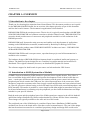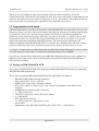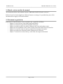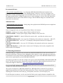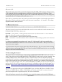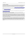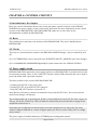
1
RK3188-SOM-EVB
Shield of peripherals
USER’S MANUAL
Document revision C, November 2015
Designed by OLIMEX Ltd, 2015
All boards produced by Olimex LTD are ROHS compliant
OLIMEX© 2015
RK3188-SOM-EVB user's manual
DISCLAIMER
© 2015 Olimex Ltd. Olimex®, logo and combinations thereof, are registered trademarks of Olimex Ltd. Other product
names may be trademarks of others and the rights belong to their respective owners.
The information in this document is provided in connection with Olimex products. No license, express or implied
or otherwise, to any intellectual property right is granted by this document or in connection with the sale of
Olimex products.
The hardware design of RK3188-SOM-EVB development board is considered open source hardware. The source design
files are published online and accessible by everyone.
The hardware designs of RK3188-SOM and RK3188-SOM-4GB development boards are considered intellectual
property to Olimex. Hardware schematics are shared with the customers. However, the board layout files are considered
copyright material and would not be shared.
The software is released under GPL.
It is possible that the pictures in this manual differ from the latest revision of the board.
The product described in this document is subject to continuous development and improvements. All particulars of the
product and its use contained in this document are given by OLIMEX in good faith. However all warranties implied or
expressed including but not limited to implied warranties of merchantability or fitness for purpose are excluded. This
document is intended only to assist the reader in the use of the product. OLIMEX Ltd. shall not be liable for any loss or
damage arising from the use of any information in this document or any error or omission in such information or any
incorrect use of the product.
This evaluation board/kit is intended for use for engineering development, demonstration, or evaluation purposes only
and is not considered by OLIMEX to be a finished end-product fit for general consumer use. Persons handling the
product must have electronics training and observe good engineering practice standards. As such, the goods being
provided are not intended to be complete in terms of required design-, marketing-, and/or manufacturing-related
protective considerations, including product safety and environmental measures typically found in end products that
incorporate such semiconductor components or circuit boards.
Olimex currently deals with a variety of customers for products, and therefore our arrangement with the user is not
exclusive. Olimex assumes no liability for applications assistance, customer product design, software performance, or
infringement of patents or services described herein.
THERE IS NO WARRANTY FOR THE DESIGN MATERIALS AND THE COMPONENTS
USED TO CREATE RK3188-SOM, RK3188-SOM-4GB AND RK3188-SOM-EVB. THEY
ARE CONSIDERED SUITABLE ONLY FOR RK3188-SOM, RK3188-SOM-4GB AND
RK3188-SOM-EVB, RESPECTIVELY.
Page 2 of 34
OLIMEX© 2015
RK3188-SOM-EVB user's manual
Table of Contents
DISCLAIMER............................................................................................................. 2
CHAPTER 1: OVERVIEW........................................................................................5
1. Introduction to the chapter.......................................................................................................5
1.1 Introduction to SOM (System-On-a-Module).......................................................................5
1.2 Target market of the board.....................................................................................................6
1.3 Features of RK3188-SOM-EVB............................................................................................. 6
1.4 Board versions used in the manual........................................................................................ 7
1.5 Document organization........................................................................................................... 7
CHAPTER 2: BOARD LAYOUT.............................................................................. 8
2.1 Board layout (top view)...........................................................................................................8
CHAPTER 3: SETTING UP THE RK3188-SOM-EVB BOARD...........................9
3. Introduction to the chapter.......................................................................................................9
3.1 Electrostatic and electrical polarity warning........................................................................ 9
3.2 Requirements........................................................................................................................... 9
3.3 Powering the board................................................................................................................10
3.4 Button functions..................................................................................................................... 11
3.5 Accessing the board................................................................................................................11
3.5.1 HDMI monitor..............................................................................................................................................12
3.5.2 SSH via Ethernet..........................................................................................................................................13
3.5.3 LCD display..................................................................................................................................................13
3.6 Software support....................................................................................................................14
CHAPTER 4: CONTROL CIRCUITY................................................................... 15
4. Introduction to the chapter.....................................................................................................15
4.1 Reset........................................................................................................................................15
4.2 Clocks......................................................................................................................................15
4.3 Power supply circuit.............................................................................................................. 15
CHAPTER 5: CONNECTORS AND PINOUT......................................................17
5. Introduction to the chapter.....................................................................................................17
5.1 UART_DEBUG pins..............................................................................................................17
5.2 UEXT connectors...................................................................................................................18
5.2.1 UEXT1...........................................................................................................................................................18
5.2.2 UEXT2...........................................................................................................................................................19
5.3 PWR jack................................................................................................................................19
5.4 USB_OTG interface...............................................................................................................20
5.5 USB_HOST connectors.........................................................................................................21
5.6 Ethernet connector................................................................................................................ 21
5.7 HDMI connector.................................................................................................................... 22
5.8 EXT connectors......................................................................................................................22
5.8.1 EXT-1 40-pin connector...............................................................................................................................23
5.8.2 EXT-2 40pin connector................................................................................................................................ 24
5.9 LCD 40pin connector.............................................................................................................25
Page 3 of 34
OLIMEX© 2015
RK3188-SOM-EVB user's manual
5.10 RK3188-GPIOX connectors................................................................................................26
5.11 Jumper description.............................................................................................................. 26
5.12 Additional hardware components...................................................................................... 26
CHAPTER 6: SCHEMATICS..................................................................................27
6. Introduction to the chapter.....................................................................................................27
6.1 Eagle schematic......................................................................................................................27
6.2 GPIO map...............................................................................................................................28
6.3 Physical dimensions...............................................................................................................29
CHAPTER 7: REVISION HISTORY AND SUPPORT........................................ 30
7. Introduction to the chapter.....................................................................................................30
7.1 Document revision................................................................................................................. 30
7.2 Board revision........................................................................................................................ 30
7.3 Useful web links and purchase codes...................................................................................30
7.4 How to purchase?...................................................................................................................31
7.5 Order codes.............................................................................................................................31
7.6 Frequently asked questions...................................................................................................32
7.7 Product support..................................................................................................................... 34
Page 4 of 34
OLIMEX© 2015
RK3188-SOM-EVB user's manual
CHAPTER 1: OVERVIEW
1. Introduction to the chapter
Thank you for choosing this expansion board from Olimex! This document provides a user’s guide
for the RK3188-SOM-EVB board. As an overview, this chapter gives the scope of this document
and lists the board’s features. The document’s organization is then detailed.
RK3188-SOM-EVB lacks a main processor. That is why it is typically used together with RK3188SOM. RK3188-SOM-EVB is a hardware extension to another Olimex board – RK3188-SOM. This
extension board provides most of connectors and peripherals needed for a full evaluation of the
RK3188 processor.
RK3188-SOM itself features the main processor and enables code development of applications
running on the RK3188 microcontroller, manufactured by Rockchip Technology from China.
In our web-shop the product named “RK3188-SOM-EVB” includes two items – RK3188-SOM4GB and RK3188-SOM-EVB.
RK3188-SOM-EVB board is an open-source, open-hardware project and all documentation is
available to the customer.
The hardware design of RK3188-SOM development board is considered intellectual property to
Olimex. The hardware layout design files are considered copyright material and would not be
distributed. The original schematics, however, are distributed in popular file format.
The software support for both boards is open-source and released under GPL license.
1.1 Introduction to SOM (System-On-a-Module)
OLIMEX System-on-Module (SOM) boards are powerful Linux-capable boards. They follow a
low-cost modular design which allows rapid product development. Each of these boards has two
parts – a main part which nests the processor, the memory, and the power control unit and the
peripheral part which contains the USB ports, the video output and most of the connectors. SOM
designs are targeted at customers who want to apply custom modifications and own solutions based
on a specific processor without having to deal with multi layer PCBs with controlled impedance and
BGA assembly. This makes it possible to create simple boards (that might be manufactured by your
local board manufacturer) containing only the peripherals you need with the dimensions and shape
suitable for your specific solution.
Both the main part and the peripheral part of the SOM system have support in the official Android
and Debian images distributed by Olimex and maintained by Olimex and the Linux community.
These images are typically available at the wiki articles of the boards.
The peripheral part of the SOM design is considered Open Source HardWare (OSHW) and the
customer has access to the board source files that we used to manufacture it. The part of the design
that has the main microcontroller is considered proprietary design and design files would not be
Page 5 of 34
OLIMEX© 2015
RK3188-SOM-EVB user's manual
shared. If you are looking for open source design of the processors used please check the
OLinuXino boards. OLinuXino board designs are fully open source but harder to implement in own
solutions and require more of a hardware experience to do so. Nevertheless, OLinuXino boards are
pretty good choice for evaluating the capabilities of the embedded processors.
1.2 Target market of the board
RK3188-SOM-EVB is typically used altogether with RK3188-SOM. As mentioned in the previous
chapter the board is meant to serve as an example that helps the customer in creating custom board
of peripherals. In that case, the board's target market is suitable for embedded programming
enthusiasts, Linux and Android gadget fans (they can just use the board as a media center or fully
functional Linux-PC, for instance) and also professionals (since its low cost makes it very good
solution for application-orientated embedded systems). The reason for this alteration is the
additional hardware that RK3188-SOM-EVB – it provides direct HDMI output and easier ways to
connect peripherals to the board. Generally, the processor's features become easier to access.
It is highly recommended to use RK3188-SOM with RK3188-SOM-EVB initially, unless you have
previous experience with SOM or OLinuXino boards manufactured by OLIMEX.
If you are not interested into implementing the RK3188-SOM design into your own production it
might be a better idea to take a look at the OLinuXino boards (like A20-OLinuXino-MICRO or
A20-OLiuXino-LIME2).
1.3 Features of RK3188-SOM-EVB
The product called RK3188-SOM-EVB includes both RK3188-SOM-EVB (board of peripherals)
and RK3188-SOM (main board).
The board of peripherals RK3188-SOM-EVB has the following set of features:
•
•
•
•
•
•
•
•
•
•
•
•
RK3188-SOM(-4GB) matching connectors
Power barrel jack, +6V to +16V DC
HDMI video output with a standard connector
LCD video output on a 40 pin at 0.1" step connector (compatible with Olimex LCD
displays)
100Mb Ethernet interface with a connector
2 × UEXT connectors
USB-OTG with power control and current limiter
4 × USB HOST
RTC with battery back-up
2 × GPIO connectors × 40 pin @ 0.1" step
Power LED
Dimensions of the RK3188-SOM-EVB part: (5.45×3.35)" ~ (138×85)mm
Page 6 of 34
OLIMEX© 2015
RK3188-SOM-EVB user's manual
1.4 Board versions used in the manual
The documents follows the hardware layout of RK3188-SOM-EVB board revisions C.
Different board revisions might have different features or settings. It is possible that parts of this
document do not apply to all board revisions.
1.5 Document organization
Each section in this document covers a separate topic, organized as follows:
– Chapter 1 is an overview of the board usage and features
– Chapter 2 contains the general board diagram and layout
– Chapter 3 provides a guide for quickly setting up the board and software notes
– Chapter 4 is an explanation of the control circuitry associated with the microcontroller
– Chapter 5 covers the connector pinout, peripherals and jumper description
– Chapter 6 provides the schematics and the dimensions of the board
– Chapter 7 contains the revision history, useful links and support information
Page 7 of 34
OLIMEX© 2015
RK3188-SOM-EVB user's manual
CHAPTER 2: BOARD LAYOUT
2.1 Board layout (top view)
Here you get acquainted
with the main parts of the
board. The picture below
shows the top side of the C
hardware revision of the
RK3188-SOM-EVB board
with RK3188-SOM
attached. Only the top side
of the board is shown since
there are no peripherals at
the bottom side.
The picture highlights the
most important parts.
The names used on the
board might differ from
the names used below to
describe them. For the
actual names check the
RK3188-SOM-EVB board
itself.
Page 8 of 34
OLIMEX© 2015
RK3188-SOM-EVB user's manual
CHAPTER 3: SETTING UP THE RK3188-SOM-EVB BOARD
3. Introduction to the chapter
This section helps you set up the SOM development board for the first time. Please consider first
the electrostatic warning to avoid damaging the board, then discover the hardware and software
required to operate the board. The procedure to power up the board is given, and a description of the
default board behavior is detailed.
3.1 Electrostatic and electrical polarity warning
The RK3188-SOM-EVB board is shipped in a protective anti-static package. The board must not be
exposed to high electrostatic potentials. A grounding strap or similar protective device should be
worn when handling the board. Avoid touching the component pins or any other metallic elements.
Ensure that your development board gets attached to properly working hardware. For example, it is
common for cheap HDMI monitors to lack grounding. Avoid TVs which have no grounding on their
power supply cable! If you can’t avoid them try to add the grounding yourself.
If you connect other electrical devices to the SOM board make sure that they have equal electrical
polarity. For example, when you connect an HDMI cable between a TV and the RK3188-SOMEVB board it is a good idea to have them both connected to the same electrical source (to the same
utility power socket). This might be said for a serial cable connected between a PC and the board's
DEBUG port. In rare cases different polarity might cause hardware damage to the board.
3.2 Requirements
In order to set up the RK3188-SOM-EVB board optimally one or more additional items may be
needed. They might be generally placed in two categories:
Required – items that are needed in order to achieve minimum functionality;
Recommended – items that is good to have in order to be able to interact with the most important
of the features of the board;
Additional – items that provide access to additional features or expand the features of the board.
Required items:
- RK3188-SOM or RK3188-SOM-4GB – the main board featuring the RK3188 processor.
AN RK3188-SOM-4GB BOARD IS INCLUDED IN RK3188-SOM-EVB PRODUCT BY
DEFAULT, NO NEED TO ORDER IT SEPARATELY.
- External power supply unit capable of providing voltage between 6V and 16V with proper
connector – RK3188-SOM-EVB has a female DC barrel jack, suitable for 6-16V power supply.
- Output device and hardware to connect to the output device – there are different ways to interact
with the board, refer to chapter “3.5 Accessing the board” for more information.
Page 9 of 34
OLIMEX© 2015
RK3188-SOM-EVB user's manual
Recommended items:
- SD card with compatible image – by default the RK3188-SOM-4GB board included in the
package can boot Debian Linux from the NAND memory. However, if you are a beginner you
might have trouble uploading images on the NAND memory (in case you want to update or repair
the image located there). It might be quite easier to write an image to a micro SD card. Ideally the
card would be class 10 with at least 4GB of storage. Official Debian images are available at the
wiki article for the board.
Additional items:
- Small heatsink for the processor – during long video playbacks the RK3188 processor might heat
up
- Ethernet cable for wired Ethernet
Some of suggested items can be purchased from Olimex, for instance:
SY0612E – reliable power supply adapter 50Hz (for EU) 12V/0.5A
SY0612E-CHINA – cheaper power supply adapter 50Hz (for EU) 12V/0.5A
USB-SERIAL-CABLE-F – female USB serial console cable – provides the easiest way of
debugging
LCD-OLINUXINO-4.3TS – low-cost 4.3'' LCD display with touchscreen component – 480×272
LCD-OLINUXINO-7TS – low-cost 7'' LCD display with optional touchscreen component –
800×480
LCD-OLINUXINO-10TS – low-cost 10'' LCD display with optional touchscreen component –
1024×600
CABLE-IDC40-15cm – a cable used to connect an LCD display to the board; compatible with
Olimex-made LCD displays
3.3 Powering the board
RK3188-SOM gets evaluated when mounted atop RK3188-SOM-EVB. In this case the former is
powered via the latter. The power line, altogether with a number of other important processor lines,
is transferred via the 40-pin headers. RK3188-SOM receives power from RK3188-SOM-EVB, but
what are the requirements to power RK3188-SOM-EVB?
You need to provide 6V to 16V DC voltage to the power jack (named PWR) of RK3188-SOM-EVB
board. The DC barrel jack has 2.0mm inner pin and 6.3mm hole. More information about the exact
component might be found here: https://www.olimex.com/wiki/PWRJACK
Do not provide AC voltage to the RK3188-SOM-EVB board! Do not provide more than 16V of
voltage to the RK3188-SOM-EVB board!
The typical consumption of RK3188-SOM-EVB + RK3188-SOM is around 0.15A @ 10V but
might reach peaks up to 0.25A @ 10V during initial boot. These values were measured without
anything else connected to the board (e.g. no keyboard, no mouse, no LCD display, etc).
For the European customers, we also stock and sell basic power supply adapters compatible with
Page 10 of 34
OLIMEX© 2015
RK3188-SOM-EVB user's manual
the power jack.
The board can be powered by a personal computer using the USB_OTG connector. However, the
USB standards limit the maximum power available at a personal computer's USB port. Thus,
powering the board via the USB_OTG port is not recommended. Especially if you are using extra
peripherals (like LCD display, keyboard, mouse, etc.).
Note that it is normal that when the board is powered some integrated circuits might appear hotter
than others. This is perfectly normal for some electronic components – for instance – the voltage
regulators and the main processor.
3.4 Button functions
RK3188-SOM-EVB does not provide extra buttons over the RK3188-SOM board.
The three buttons located on the RK3188-SOM can also be used while the board is mounted over
RK3188-SOM-EVB. These buttons are:
POWER – power button – used to perform software turn off, software turn on – has to be held
down for at least 5 seconds to perform each action
REC – recovery button – used to wake up the board from sleep
RST – reset button – used for hardware reset of the board – before using it, please refer to the note
below
It is always recommended to perform a soft “turn off” of the board. If that is not possible then
please hold POWER button down for a few seconds to “turn off the board”. Then you are free to
remove the power supply.
If you disconnect the power supply (either the USB, the battery or the power jack) before turning
off the board you may corrupt your SD card. If your board has NAND memory you can corrupt the
image located on the NAND memory.
3.5 Accessing the board
The typical and recommended way of interacting with RK3188-SOM-EVB board is via a serial
cable connected between the RK3188-SOM's UART-DEBUG header and a personal computer. You
would probably need a cable suitable for such a connection due to the fact that most personal
computers lack a serial port nowadays. Even if you have serial port you should respect the CMOS
levels of the board which are incompatible with the TTL levels of your computer. We distribute a
ready-to-use plug-and-play cable – it is called USB-SERIAL-CABLE-F. Even if you already have
such a cable or you decide to purchase it elsewhere it is advisable to check this product page for a
reference: https://www.olimex.com/Products/Components/Cables/USB-Serial-Cable/USB-SerialCable-F/
You need to connect the cable to the UART-DEBUG pins as follows: RX line to UART0-TX pin;
TX line to UART0-RX pin; GND to GND. Make sure that the serial cable is connected to your
personal computer and recognized properly after driver installation.
After the hardware connection is established, open a terminal program on the serial (COM) port
Page 11 of 34
OLIMEX© 2015
RK3188-SOM-EVB user's manual
which the cable is associated with. The typical baud rate is 115200, the rest of the settings should be
left as per default.
After everything else is set, you would need to power the board as explained in “3.3 Powering the
board”.
In the command line interface of the official Debian images you are automatically logged as root.
The default superuser username/password combination in the GUI (XFCE4) of the official images
is: olimex/olimex.
When RK3188-SOM is attached to RK3188-SOM-EVB, in addition to the serial communication,
you might also use one or more of the following mediums to interact with the board:
1. a monitor via the HDMI connector
2. SSH with a remote computer via LAN connector
3 a display via the LCD_CON connector
More details on each of the connections might be found in the consequent sub-chapters.
Note that not all interface options are available for all images. The official Debian image should
give you the most possible options of interfacing the board!
Using HDMI, LCD_CON or LAN might require additional configurations. Furthermore, it is
possible to corrupt the output settings over those interfaces and, thus, lose the output. In such cases,
you can always use the serial cable USB-SERIAL-CABLE-F as a reliable way to establish
connection to the board.
3.5.1 HDMI monitor
All official for RK3188-SOM have HDMI output enabled by default. The board would work out-ofthe-box with a native HDMI monitor (if you use RK3188-SOM + RK3188-SOM-EVB altogether
with one of the official Debian images from the board's wiki article).
Make sure to use a tested HMDI cable.
The default HDMI resolution in the official images is 720p (1280×720p at 60Hz). In order to
change that setting the video output on the LCD display you would need to run a configuration
script (if you use Debian Linux) or download a suitable image (if you use Android).
More information about the video output settings and the usage of video settings script might be
found in RK3188-SOM's user's manual (“3.7 Changing the default image resolution”)
Page 12 of 34
OLIMEX© 2015
RK3188-SOM-EVB user's manual
3.5.2 SSH via Ethernet
By default the board IP address is 192.168.1.254. This allows you to connect to the board using an
SSH client (for example “telnet” or “puTTY”) then you have to use this address. You can change
this address from /etc/network/interfaces file.
Note that for internet connection you have to set your gateway address in /etc/network/interfaces
file and you have to set your DNS server in /etc/resolv.conf (for example “nameserver
192.168.1.1”).
The port used for the connection the default one – port 22.
3.5.3 LCD display
One of the ways to interact with the board is via an external display (with or without touchscreen
component). The 40-pin male connector LCD_CON has the typical 0.1'' pin step. All Olimex
displays have corresponding 40-pin male connector. You would only need a 0.1'' female-female
cable for the hardware connection.
In order to get the video output on the LCD display you might need either to run at least once a
configuration script (if you use Debian Linux) or download a suitable image (if you use Android).
Video output settings are hard-coded in Android images. More information about the video output
settings and the usage of video settings script might be found in RK3188-SOM's user's manual (“3.7
Changing the default image resolution”).
The displays recommended for the board at the moment of writing might be found in the table
below:
Display name
LCD-OlinuXino-4.3TS
LCD-OLinuXino-7
LCD-OLinuXino-7TS
LCD-OLinuXino-10
LCD-OLinuXino-10TS
Size of
display
in inches
4.3
7
7
10.1
10.1
Native
resolution
in pixels
480×272
800×480
800×480
1024×600
1024×600
Official
Debian image
support
Yes
Yes
Yes
Yes
Yes
Official
Android image
support
No
Yes
Yes
Yes
Yes
Link to product
page
Product
Product
Product
Product
Product
page
page
page
page
page
The displays whose names contain “TS” - include a resistive touch screen component.
Each of the displays listed in the table above has a connector suitable for a cable that can be
purchased from Olimex:
CABLE-IDC40-15cm – 15cm long cable suitable for 0.1'' step connectors – Product page
Page 13 of 34
OLIMEX© 2015
RK3188-SOM-EVB user's manual
3.6 Software support
At the moment, we provide ready-to-use Debian Linux images suitable for the NAND memory of
the board or micro SD card. We also provide instructions and sources of these releases. These
images might be downloaded for free and modified as the user wishes. The latest images and
updates are featured at the wiki article of the device: https://www.olimex.com/wiki/RK3188-SOM.
We usually try to provide extra details and best experiences with our products at our wordpress
page: http://olimex.wordpress.com/.
Another useful place is the Olimex forums where a lot of people share their experience and advice:
https://www.olimex.com/forum/.
The official images are a constant work-in-progress – newer releases are packed with better
hardware support, newer kernels and extra features.
You are more than welcome to send or share your suggestions and ideas at our e-mail, the public
forums or irc channel. We would attempt to help in almost every case. We listen to the feedback and
if the majority of users suggest a software change or update we try to implement such. Customer
feedback is very important for the overall state of the software support. However, do not expect full
Linux or Android software support.
We can share our experience. We can give you full details for things we have tried. We can point
you to a resource or a guide. We can give you general directions to solving a specific problem or
places to look for more information. However, we won’t install a piece of software for you or write
custom program for you. We won't provide a specific software solution to a specific software
problem.
Page 14 of 34
OLIMEX© 2015
RK3188-SOM-EVB user's manual
CHAPTER 4: CONTROL CIRCUITY
4. Introduction to the chapter
Here you can find information about reset circuit and quartz crystals locations on the RK3188SOM-EVB, the power supply circuit is also briefly discussed. For more information on the control
circuitry of the RK3188-SOM + RK3188-SOM-EVB, make sure to also check on the
documentation available for RK3188-SOM.
4.1 Reset
The board doesn't extend the reset features of the RK3188-SOM. The reset is handled by the
RK3188-SOM.
4.2 Clocks
There are two external quartz crystals in the RK3188-SOM-EVB design – they are named Q1 and
Q2.
Q1 is 32.768KHZ/6pF crystal connected to the PCF8563T (the RTC_MODULE part of the design).
Q2 is 12.000MHz/HC-49SM/SMD/20ppm/20pF crystal connected to the USB hub GL850G.
4.3 Power supply circuit
RK3188-SOM-EVB extends the power supply options over RK3188-SOM. It provides a barrel jack
for external powering. There is also a USB OTG interface (mini USB connector) that can be used to
power the board from a personal computer.
The three possible ways to power RK3188-SOM-EVB:
- providing (6-16)V DC at the power jack
- providing 5V DC at pin #39 of EXT2 connector
- using the USB_OTG interface to provide 5V
Note that the coin battery connector is intended to keep only the RTC alive. You can't power the
whole board using a coin battery!
The recommended way of powering the board is via the PWR jack with 6-16V DC with a power of
5W (e.g. 6Vx0.8A; 16Vx0.3A). This will make the board fully powered and able to supply all the
peripherals connected to it.
Important: Not all USB ports would be able to provide enough power for the board. Try using
another USB port/USB hub or a cable of higher quality. Do not rely on the USB_OTG as a single
power source!
The power supply is handled mainly by ACT8846 power management system.
Page 15 of 34
OLIMEX© 2015
RK3188-SOM-EVB user's manual
The consumption of the combination RK3188-SOM-EVB + RK3188-SOM-4GB is between 0.10A
and 0.15A when RK3188-SOM-EVB is connected to a 10V voltage source (provided at the board's
PWR jack).
The current consumed might have peaks as high as 0.25A @ 10V during start-up when different
modules are initialized.
Page 16 of 34
OLIMEX© 2015
RK3188-SOM-EVB user's manual
CHAPTER 5: CONNECTORS AND PINOUT
5. Introduction to the chapter
In this chapter are presented the connectors that can be found on the RK3188-SOM-EVB board all
together with their pinout and notes about them. For the connectors available at the RK3188-SOM
board, please refer to its own user's manual. Jumpers functions are described. Notes and info on
specific peripherals are presented. Notes regarding the interfaces are given.
5.1 UART_DEBUG pins
The direct communication method to the heart of the setup (RK3188-SOM-4GB + RK3188-SOMEVB) is via the serial interface. Such interface is available at the DEBUG-UART connector located
on the RK3188-SOM-4GB board (five male pins near the edge of the board). It is capable of
interfacing the COM port of your computer with the help of your favorite terminal program (puTTy,
minicom, picocom, teraterm, etc). You can use USB-SERIAL-CABLE-F to interface
DEBUG_UART – that allows you to debug the board with a personal computer with a free USB
port. In case of a video output problem a cable might provide the needed feedback and would
greatly reduce the efforts needed to repair the board or to adjust the software settings.
By default only DEBUG_UART is defined as a port suitable for serial debug.
If you decide to make your own debugging cable you would need to consider that the levels at
board's DEBUG-UART are in CMOS level (3.3V) and you would need a convertor to bring them to
the TTL level of your computer or cable! That is true for the RX and TX also!
UART_DEBUG
Pin # Printed name
Signal name
Processor pin
1 5.0V
+5V
-POWER CIRCUIT-
2 GND
GND
-POWER CIRCUIT-
3 UART0-TX
UART2-TX
P19
4 UART0-RX
UART2-RX
P20
5 GND
GND
-POWER CIRCUIT-
Consider the table above when connecting the USB-SERIAL-CABLE-F according to the wire color
code. The RX line of the cable (GREEN wire) should go to TX line of the target board; the TX line
of the cable (RED wire) should go to the RX line of the target board. The BLUE wire should go to
the target's GND line. For more information please refer to chapter “3.5 Interacting with the board”.
The UART_DEBUG header can also be used to power a stand-alone RK3188-SOM. This is the
recommended way of powering a standalone RK3188 board. The voltage input pin (+) is named
“5.0V” and it is suitable for 5V DC external power supply unit. One of the two GND pins can be
used as ground (-). The required current may vary depending on the peripherals connected to the
board. The power supply should be capable of providing at least 2.5W. For the powering, we are
only interested in the 5.0V (+) pin and the GND (-) pin.
Page 17 of 34
OLIMEX© 2015
RK3188-SOM-EVB user's manual
5.2 UEXT connectors
Universal EXTension (UEXT) is a connector layout which includes power, ground and three
popular buses: data UART, I2C, and SPI. The UEXT connector consists of 10 pins, in a two row by
five male pin configuration, with a plastic keyed-shroud. All pins have a spacing of 0.1 inch (2.54
mm). The UEXT connectors are typically used as an interface for the Olimex's UEXT modules
(usually boards with MOD- prefix in their commercial names).
The general layout of every UEXT connector follows the picture below:
For more information on UEXT please visit:
https://www.olimex.com/Products/Modules/UEXT/resources/UEXT.pdf
RK3188-SOM-EVB has two UEXT connectors. Hardware-wise each of them has its own UART,
own I2C and own SPI. The pinout of the connectors might be found in the following sub-chapters.
5.2.1 UEXT1
UEXT1 nests UART0, I2C0, and SPI0 interfaces.
Signal
Pin#
name
1
3
5
7
9
3.3V
GPIO1_A1/
UART0_TX
GPIO1_D1/
I2C0_SCL
GPIO1_A4/
SPI0_MISO
GPIO1_A6/
SPI0_SCK
UEXT1* connector
RK3188
Header; pin#
Pin #
pin
RK3188–GPIO2; 1
-POWER
2
LCD_CON; 2
CIRCUITRK3188–GPIO4; 38
L19
4
RK3188–GPIO3; 33
G21
6
RK3188–GPIO4; 32
AA12
8
RK3188–GPIO4; 28
AA13
10
pinout
Signal
name
GND
GPIO1_A0/
UART0_RX
GPIO1_D0/
I2C0_SDA
GPIO1_A5/
SPI0_MOSI
GPIO1_A7/
SPI0_CSN0
RK3188
pin
-POWER
Any RK3188-GPIOX; 2
CIRCUITHeader; pin#
RK3188–GPIO4; 40
L20
RK3188–GPIO3; 31
G22
RK3188–GPIO4; 30
Y16
RK3188–GPIO4; 26
AB21
*The first column represents the pin number of the signal in the UEXT connector. The second column has the signal name as per
hardware design files and schematic. The column named “Header; pin#” shows the exact header pin where the signal might be
found. The “RK3188 pin” column shows where the signal connects with the Rockchip's RK3188 processor – this can be tracked in
the RK3188-SOM's schematic, starting from the header.
Page 18 of 34
OLIMEX© 2015
RK3188-SOM-EVB user's manual
5.2.2 UEXT2
UEXT2 nests UART3, I2C4, and SPI1 interfaces.
Pin#
Signal
name
Header; pin#
1
3.3V
RK3188–GPIO2; 1
LCD_CON; 2
3
5
7
9
GPIO1_B3/
UART3_TX
GPIO1_D7/
I2C4_SCL
GPIO0_D4/
SPI1_MISO
GPIO0_D6/
SPI1_CLK
RK3188–GPIO3; 11
RK3188–GPIO2; 40
RK3188–GPIO4; 33
RK3188–GPIO4; 37
UEXT2* connector pinout
RK3188
Signal
Pin #
pin
name
-POWER
2
GND
CIRCUITGPIO1_B2/
T22
4
UART3_RX
GPIO1_D6/
AA15
6
I2C4_SDA
GPIO0_D5/
U23
8
SPI1_MOSI
GPIO0_D7/
T21
10
SPI1_CSNO
RK3188
pin
-POWER
Any RK3188-GPIOX; 2
CIRCUITHeader; pin#
RK3188–GPIO3; 9
U21
RK3188–GPIO2; 39
AC11
RK3188–GPIO4; 35
R21
RK3188–GPIO4; 39
T20
*The first column represents the pin number of the signal in the UEXT connector. The second column has the signal name as per
hardware design files and schematic. The column named “Header; pin#” shows the exact header pin where the signal might be
found. The “RK3188 pin” column shows where the signal connects with the Rockchip's RK3188 processor – this can be tracked in
the RK3188-SOM's schematic, starting from the header.
5.3 PWR jack
The power jack used is the typical one used by Olimex in most of our products – the DC barrel jack
has 2.0mm inner pin and 6.3mm hole. More information about the exact component might be found
here: https://www.olimex.com/wiki/PWRJACK.
You should provide 6 to 16 volts direct current and the required current may vary depending on the
peripherals connected to the board. The power supply you use should be capable of providing at
least 500mA of current.
Pin #
Signal
1
POWER INPIT
2
GND
More info about the power supply can be found in chapter 4 of this manual.
Page 19 of 34
OLIMEX© 2015
RK3188-SOM-EVB user's manual
5.4 USB_OTG interface
The USB_OTG interface of RK3188-SOM-EVB uses USB mini connector.
The USB_OTG connector can be used to upgrade the Linux image on the NAND memory of the
board if you have RK3188-SOM-4GB. There are few requirements to establish a proper connection:
1) A personal computer that would act as a host PC and would run the software suitable for
upgrading. You need also a suitable USB cable with mini USB connector to establish the hardware
link between the host PC and the RK3188-SOM-EVB board.
The software for upgrading under Windows is called “Rockchip Batch Tool” and you can download
it at this location: download "Rockchip Batch Tool" from our Google Drive.
2) The host PC needs drivers to be able to recognize the board in bootloader mode.
The driver installer can be download from here: download “RK Driver Assistant” from our Google
Drive.
3) The board needs to be in bootloader mode to be able to connect to the host PC. In order to enter
bootloader mode – press and hold down the REC button and apply the power supply. Release the
REC button. Connect the USB cable to the mini USB connector.
Refer to chapter “3.3 Preparing the OS to boot” of RK3188-SOM's user's manual for more details.
USB_OTG connector
Pin # Signal name Header; pin#
1 +5V_OTG_PWR RK3188–GPIO4; 1
2 OTG_DM
RK3188–GPIO4; 8
3 OTG_DP
RK3188–GPIO4; 6
4 OTG_ID
RK3188–GPIO4; 3
5 GND
Any RK3188–GPIOX; 2
RK3188 pin
-POWER CIRCUITAB14
AC14
Y17
-POWER CIRCUIT-
The connector case is also grounded. The schematic might be seen below:
The USB_OTG features Low Loss Power Distribution Switch SY6280 which protects the board in
case the devices you have plugged to the USB_OTG attempt to draw more current than 523mA
Page 20 of 34
OLIMEX© 2015
RK3188-SOM-EVB user's manual
combined. The maximum current available on the 5V USB_OTG is exactly 523mA.
The SY6280 responsible for the USB_OTG is enabled by GPIO2_D7/USB-OTG-DRV (processor
pin F22), thus the USB_OTG is also controlled by the same signal.
There are two parts of a successful OTG device/host mode switch and usage – hardware part and
software part.
The hardware part is the cable – to use the OTG as a host you would need a mini USB to USB
adapter cable. Do not confuse micro and mini USB! To use it as a device simply use mini USB to
mini USB cable.
The software part is loading a kernel module responsible for the behavior of the board while in
device mode. If such software is not enabled or missing in the official distribution – you would
need, respectively, either to load the module or rebuild the kernel to enable the module. There are
several modules that you might need depending on what your goals are.
5.5 USB_HOST connectors
There are four USB_HOST connectors. All of them are handled by the built-in USB 2.0 hub
GL850G-HHGXX.
The hub itself uses USB-HOST_DM and USB-HOST_DP signals that go to RK3188–GPIO4 (pins
10 and 12, respectively). From there the signal lines go the RK3188-SOM and to the RK3188 itelf
at pins AB16 and AC14.
All of these USB_HOST slots are connected to a single low loss power distribution switch SY6280
which protects the board in case the devices you have plugged to each level USB_HOST try to
draw more than the allowed current. The total current available for all of the hosts is 1000mA. The
GND is common for all four levels of the USB_HOST.
5.6 Ethernet connector
The LAN connectivity is handled by Microchip's LAN8710A-EZC. The LAN8710A is a low-power
10BASE-T/100BASE-TX physical layer (PHY) transceiver with variable I/O voltage that is
compliant with the IEEE 802.3-2005 standards.
The Ethernet connector is grounded according to the standard (check GND1 and GND2 lines on the
schematics).If you use Linux then the Ethernet connector might be used for SSH connection to the
board. If you lack any other option for debugging it might be hard to guess the correct IP of the
board since it has DHCP enabled by default (especially if you are in a large network). It is good idea
to check the default settings by exploring the Linux image settings. Those are usually stored in:
/etc/network/interfaces
For DHCP you need to enable auto detection and dhcp as shown below:
auto eth0
iface eth0 inet dhcp
Page 21 of 34
OLIMEX© 2015
RK3188-SOM-EVB user's manual
Important: You can configure static/DHCP-given IP addresses in /etc/network/interfaces. For setting
a static address please follow the pattern below:
auto eth0
iface eth0 inet static
address 192.168.1.5
netmask 255.255.255.0
gateway 192.168.1.254
Important: In some Debian images it is possible that the Ethernet doesn't get auto-detected during
boot-up. This is done on purpose because if there is auto-detection enabled and you don't want to
use the Ethernet connector or you have forgotten to plug a cable the start-up would be greatly
delayed. This might be problem in the first start-up to users counting only on SSH connection. You
can enable the Ethernet after a successful boot-up with:
ifconfing -a
dhclient eth#(as seen after after the ifconfing command)
LED
LED1
LED2
RJ45 LED COLOR CODE
Color
Green
Yellow
Usage
Link status
Activity status
5.7 HDMI connector
The HDMI video output is handled by IT66121FN: Low Power Transmitter with HDMI1.4 3D.
The part of the schematic that describes the HDMI module is shown below:
5.8 EXT connectors
There are two GPIO connectors at the top side of RK3188-SOM-EVB named EXT1 and EXT2
(short from EXTernal1 and EXTernal2). They ease the access to some of the free processor's pins.
Each of the connectors has two rows of male pins at 0.1'' step.
Page 22 of 34
OLIMEX© 2015
RK3188-SOM-EVB user's manual
Below you would find tables with the signal at each pin. To understand better what each processor
pin does it might be a good idea to refer to the datasheet of the RK3188 processor. The schematic of
the main board RK3188-SOM might also help you identify the main function of the pins.
You should at least refer to this RK3188-SOM's GPIO table: RK3188-SOM GPIO PDF
The EXT headers provide additional ways to power the board. However, double check your
hardware setup since there is always a possibility of accidental short-circuits (especially if you
power the board from multiple sources).
It is always recommended to use the mounted connectors to power the board and use the EXT pins
related to the power circuit only for measurements.
5.8.1 EXT-1 40-pin connector
At the EXT-1 you can find the NAND flash memory signals. You can also find the pins responsible
for the on-board LEDs. There are free PWMs available on EXT-1 connector.
Most of the signals of EXT-1 are routed from RK3188-GPIO3 and RK3188-GPIO4.
Pin # Signal name
1 VCC_1.8
3 ADC_IN0
5 NWP
7 NDQ0
9 NDQ1
11 NDQ2
13 NDQ3
15 NDQ4
17 NDQ5
19 NDQ6
21 NDQ7
23 GPIO0_D0/FLASH_DQS
25 GPIO0_D1/FLASH_CSN1
27 GPIO0_D2/FLASH_CSN2
29 GPIO0_D3/FLASH_CSN3
31 GPIO1_C0
33 GPIO1_C4
35 GPIO1_B4
37 GPIO1_B5
39 GPIO1_B7/SDO
EXT-1 connector
Processor pin
Pin # Signal name
-POWER CIRCUIT2 GND
H21
4 ADC_IN2
Y18
6 NRB0
AC20
8 NRE
AB21
10 NCLE
AA21
12 NALE
Y22
14 NWE
AC22
16 NCE0
Y21
18 GPIO0_B4/LED1
AC23
20 GPIO0_B6/LED2
AB22
22 GPIO3_D5/PWM2
AB20
24 GPIO3_D6
Y20
26 GPIO0_C0
AA22
28 GPIO0_C1
AA20
30 GPIO0_C2
Y13
32 GPIO0_C3
AB13
34 GPIO0_C4
T23
36 GPIO0_C5
P21
38 GPIO0_C6
AB12
40 GPIO0_C7
Page 23 of 34
Processor pin
-POWER CIRCUITH19
W17
AB19
W18
U19
H19
Y19
AC10
Y11
P22
P23
W22
W20
W21
Y23
AB23
V21
V19
W23
OLIMEX© 2015
RK3188-SOM-EVB user's manual
5.8.2 EXT-2 40pin connector
At the EXT-2 you can find the camera signals. Most of the signals of EXT-2 are routed from
RK3188-GPIO1.
Pin #39 can be used to power the board directly by providing regulated 5V of voltage.
GPIO pin#
1
3
5
7
9
11
13
15
17
19
21
23
25
27
29
31
33
35
37
39
Signal name
3.3V
3.3V
GPIO0_A1
GPIO0_A5
GPIO0_A6
GPIO0_A7
CIF_D0
CIF_D1
CIF_D2
CIF_D3
CIF_D4
CIF_D5
CIF_D6
CIF_D7
CIF_D8
CIF_D9
CIF_D10/SDA
GPIO2_D4
GPIO3_A0
+5V
EXT2 connector
Processor pin#
GPIO pin#
-POWER CIRCUIT2
-POWER CIRCUIT4
Y6
6
W6
8
W11
10
AC7
12
AC2
14
AC1
16
AB3
18
W1
20
W2
22
W3
24
V4
26
Y3
28
Y4
30
W4
32
AA4
34
14
36
24
38
-POWER CIRCUIT40
Page 24 of 34
Signal name
GND
RESET
GPIO0_B0
GPIO0_B1
GPIO0_B2
GPIO0_B7
GPIO1_A2
GPIO1_A3
CIF_HREF
CIF_CLKI
CIF_CLKO
CIF_VSYNC
CIF_D15
CIF_D14
CIF_D13
CIF_D12
CIF_D11/SCL
GPIO2_D5
GPIO3_B1
GND
Processor pin#
-POWER CIRCUITAC5
W8
AA7
AB6
AA11
L21
L23
AB2
V2
Y5
AA3
AB1
AA2
Y2
Y1
AB4
U3
M22
-POWER CIRCUIT-
OLIMEX© 2015
RK3188-SOM-EVB user's manual
5.9 LCD 40pin connector
The LCD pins are led out on a separate 40pin connecter for the ease of connecting an LCD. We
have tested the ability of the board to interact with such a display. They allow the user to attach
additional hardware, check readings or perform hardware debug.
Important: you need additional 40PIN ribbon cable to connect an Olimex display and the
LCD_CON.
The LCD connector is suitable for a number of Olimex displays and touchscreen panels with
different native resolution – the smallest available is the 4.3'' one called LCD-OLinuXino-4.3TS
with native screen resolution of 480×272, through the 7'' one named LCD-OlinuXino-7TS with
800×480, to the 1024×600 10.1'' LCD-OLinuXino-10TS.
Full list of recommended displays for the board might be found in chapter “3.5.3 LCD display”.
Please note that the smallest display (4.3'', 480×272) is not suitable for the official Android images
we provide.
Most of the signals of LCD are routed from LCD_CON.
The touch screen is handled by the Microchip's resistive touch screen controller AR1021.
GPIO pin#
1
3
5
7
9
11
13
15
17
19
21
23
25
27
29
31
33
35
37
39
Signal name
+5V
3.3V
LCD0_D16
LCD0_D18
LCD0_D20
LCD0_D22
LCD0_D8
LCD0_D10
LCD0_D12
LCD0_D14
LCD0_D0
LCD0_D2
LCD0_D4
LCD0_D6
LCD0_HSYNC
LCD0_CLK
LCD0_L/R
GPIO3_D7/LCD0_PWRE
XY-
LCD connector
Processor pin
GPIO pin#
-POWER CIRCUIT2
-POWER CIRCUIT4
H5
6
H3
8
H1
10
J3
12
F3
14
G5
16
G3
18
G1
20
D0
22
E2
24
E4
26
F5
28
A1
30
D2
32
NC/W11*
34
N22
36
-AR1021-I38
-AR1021-I40
Page 25 of 34
Signal name
GND
GND
LCD0_D17
LCD0_D19
LCD0_D21
LCD0_D23
LCD0_D9
LCD0_D11
LCD0_D13
LCD0_D15
LCD0_D1
LCD0_D3
LCD0_D5
LCD0_D7
LCD0_VSYNC
LCD0_DE
LCD0_U/D
GPIO3_D4/PWM1
X+
Y+
Processor pin
-POWER CIRCUIT-POWER CIRCUITH4
H2
K1
J2
F2
G4
G2
H6
E1
E3
G6
F4
B1
D3
NC/AC7*
R22
-AR1021-I-AR1021-I-
OLIMEX© 2015
RK3188-SOM-EVB user's manual
5.10 RK3188-GPIOX connectors
There are four male connectors located in the middle of the top side of RK3188-SOM-EVB. They
have a smaller step (0.05'') compared to the step of the EXT connectors (0.1'') mentioned in the
previous chapter (5.9). These connectors provide a way to attach the board with peripherals to the
main board RK3188-SOM.
The manual and schematic of the main board RK3188-SOM might help you identify the main
function of these interface pins.
The hardware connections between the RK3188 and RK3188-SOM-EVB are as follows:
1. RK-SOM's GPIO-1 connects to RK3188-SOM-EVB's RK3188 GPIO-1.
2. RK-SOM's GPIO-2 connects to RK3188-SOM-EVB's RK3188 GPIO-2.
3. RK-SOM's GPIO-3 connects to RK3188-SOM-EVB's RK3188 GPIO-3.
4. RK-SOM's GPIO-4 connects to RK3188-SOM-EVB's RK3188 GPIO-4.
5. RK-SOM's LCD_CON connects to RK3188-SOM-EVB's LCD.
IMPORTANT: the RK3188-GPIOX connectors are very fragile – if you attempt to disconnect the
RK3188-SOM board by pulling only one side out it might break! Furthermore – you might bend the
pins or the header! Use pliers or other suitable object to disconnect the connectors carefully!
5.11 Jumper description
Please note that only jumper on the board is SMT type. It is typical used for current measuring
(disconnect the jumper and place the ampermeter between the two pads). If you feel insecure of
your soldering/cutting technique it is better not to try to adjust its position.
Jumper name
Type
Board jumper
Default position
5V_E
SMT
CLOSED
Function
Used for test measurements of
voltage and amperage.
5.12 Additional hardware components
The components below are mounted on the RK3188-SOM-EVB but are not discussed above. They
are listed here for completeness:
PCF8563T – a CMOS Real-Time Clock (RTC) and calendar optimized for low power consumption.
Used for time keeping. Uses the signals I2C1_SCL, I2C1_SDA, RTC_INIT and RTC_CLKOUT.
I2C Slave Address: 0xA3 (read), 0xA2 (write). Can be kept alive in case of power loss using a coin
battery. The battery has a connector on the RK3188-SOM-EVB – 3.0V_BAT connector.
PWR_LED – turns on upon powering the board (there is also PWR LED on RK3188-SOM).
Page 26 of 34
OLIMEX© 2015
RK3188-SOM-EVB user's manual
CHAPTER 6: SCHEMATICS
6. Introduction to the chapter
In this chapter is located information about the schematics describing logically and physically
RK3188-SOM-EVB.
6.1 Eagle schematic
RK3188-SOM-EVB schematics may be found it our GitHub repository:
https://github.com/OLIMEX/SOM/tree/master/RK3188. You can download the whole repository
as .zip without having a GitHub account.
We mostly use Eagle by Cad Soft 4.16r2 for designing. However, the files should be compatible
with the latest Eagle available. Cad Soft offers a trial version of their software that allows you to
inspect schematics and board files (without being able to modify them).
This work is licensed under the Creative Commons Attribution-ShareAlike 3.0 Unported License.
To view a copy of this license, visit http://creativecommons.org/licenses/by-sa/3.0/.
If you are looking for a schematic of an older revision of the board and it isn't available at our web
site you may request it by the support e-mail.
Page 27 of 34
OLIMEX© 2015
RK3188-SOM-EVB user's manual
6.2 GPIO map
Page 28 of 34
OLIMEX© 2015
RK3188-SOM-EVB user's manual
6.3 Physical dimensions
Note that all dimensions are in mils.
Page 29 of 34
OLIMEX© 2015
RK3188-SOM-EVB user's manual
CHAPTER 7: REVISION HISTORY AND SUPPORT
7. Introduction to the chapter
In this chapter you will find the current and the previous version of the document you are reading.
Also the web-page for your device is listed. Be sure to check it after a purchase for the latest
available updates and examples.
7.1 Document revision
Document revision Changes
A, 03.04.15
Initial manual release
Additional GPIO map
B, 15.04.15
Fixed numerous spelling mistakes
C, 04.11.15
Added information about USB-OTG
Modified page
All
28
All
20
7.2 Board revision
Remember to check the schematics and the board design files to compare the differences.
Board revision
C
Notable changes
Initial release of the board
7.3 Useful web links and purchase codes
RK3188-SOM-EVB's web page is here: https://www.olimex.com/Products/SOM/RK3188/RK3188SOM-EVB/.
The user's manual of RK3188-SOM might be found here:
https://www.olimex.com/Products/SOM/RK3188/RK3188-SOM/resources/RK3188-SOM-UM.pdf
The web pages you can visit for more information about RK3188-SOM are:
https://www.olimex.com/Products/SOM/RK3188/RK3188-SOM/ and
https://www.olimex.com/Products/SOM/RK3188/RK3188-SOM-4GB/.
Wiki articles of the boards: https://www.olimex.com/wiki/RK3188-SOM and
https://www.olimex.com/wiki/RK3188-SOM-EVB
A place for general questions, FAQ or friendly talk: https://www.olimex.com/forum/.
You can get the latest hardware updates at the GitHub page:
https://github.com/OLIMEX/SOM/tree/master/RK3188.
You may may join our IRC channel #olimex @ freenode.net (http://webchat.freenode.net/?
channels=olimex).
Page 30 of 34
OLIMEX© 2015
RK3188-SOM-EVB user's manual
7.4 How to purchase?
You can purchase directly from our online shop or from any of our distributors. Note that usually it
might be faster and cheaper to purchase Olimex products from our distributors. List of confirmed
Olimex LTD distributors and resellers: https://www.olimex.com/Distributors.
Please visit https://www.olimex.com/ for more info.
7.5 Order codes
Short summary of the formal product names of the devices mentioned in this document:
RK3188-SOM – the target of this manual
RK3188-SOM-EVB – RK3188-SOM-4GB + a shield with all important peripherals (HDMI
interface, LCD connector, 100Mb Ethernet with connector, USB-OTG, 4 x USB hosts, 0.1'' GPIO
connectors, etc)
USB-SERIAL-CABLE-F – USB serial console cable female
RK3188-SOM-DEBIAN-SD – a tested class 10 micro SD card with the latest (by the time of
leaving the Olimex facilities) official Debian Linux release
LCD-OLINUXINO-4.3TS – low-cost 4.3'' LCD display with touchscreen component – 480×272
LCD-OLINUXINO-7TS – low-cost 7'' LCD display with optional touchscreen component –
800×480
LCD-OLINUXINO-10TS – low-cost 10'' LCD display with optional touchscreen component –
1024×600
ALUMINIUM-HEATSINK-20×20×6MM – heatsink radiator for better processor heat dissipation
Page 31 of 34
OLIMEX© 2015
RK3188-SOM-EVB user's manual
7.6 Frequently asked questions
Q: I powered my board and then nothing happened. What might be the problem?
A: This might be due to a number of reasons but it is recommended to try the following:
1. Download latest official Debian image from our wiki, and upload it to an SD card again. There
are instructions how to do it in the other questions below. Try if the board works now.
2. Check if your power supply provides enough current, try with different/better power supply.
3. Check the USB hub you are using, plug the USB cable directly to the back of your personal
computer, check the USB cable.
4. The board might enter sleep mode very fast (especially if the Android was turned off without the
“Quick Boot” mode being ticked on). Try pressing or holding down the PWR button for a couple of
seconds to wake it up.
Q: How do I write the Linux image to a micro SD card to use with my RK3188 board?
A: First visit the wiki article for the board and download the archive with the image. Then write the
Linux image to a microSD card.
Under Windows we use Win32 Disk Imager: http://sourceforge.net/projects/win32diskimager/
1. Download the latest official image suitable for a microSD card from the chapter above
2. Download Win32 Disk Imager from this link.
3. Insert card in your microSD card reader.
4. Launch the software.
5. Point the software to the image
6. Click "write"
Under Linux you can write the image image to the card with dd utility. This is how it can be done:
Let's say the name of the image is "debian_2g.img". It would be downloaded to the microSD card
connected to a Linux machine using one of the following commands
dd bs=4M oflag=sync if=debian_2g.img of=/dev/sdX
or
cp debian_2g.img /dev/sdX
where X is the uSD card.
The tips above can also be used to prepare a microSD card with an Android image, suitable for a
microSD card.
Page 32 of 34
OLIMEX© 2015
RK3188-SOM-EVB user's manual
Q: How to edit board configurations and definitions in the official Debian Linux?
A: The Debian Linux support for boards using Rockchip processors is not as goods as that of the
boards using Allwinner processors.
There are no configuration files for easier editing. You would need to rebuild the kernel.
Q: Is it possible to boot Debian from NAND? Do you provide such image?
A: Yes. Refer to the chapter “5.4 USB_OTG interface”. Read how to build such an image here:
https://www.olimex.com/wiki/RK3188-SOM#Booting_from_NAND
Q: How to generate boot-able SD-card Debian Linux image for RK3188-SOM?
A: Build instructions and required files for the latest Debian images might be found at the wiki page
of the board. The step-by-step instructions are available here:
https://www.olimex.com/wiki/RK3188-SOM#Building_Linux_for_RK3188-SOM
Q: How to detect and enable the Ethernet controller (if it is disabled by default)?
A: You can enable it by following these two steps:
1. To check under what name the LAN is associated write "ifconfig –a"
2. If, for example, it is under eth0 name, then write: "dhclient eth0"
This should enable the Ethernet and then SSH would also be available.
You can also enable auto detection of Ethernet on power-up by removing the comment #auto eth0 in
/etc/network/interfaces in the Linux image.
Page 33 of 34
OLIMEX© 2015
RK3188-SOM-EVB user's manual
7.7 Product support
For product support, hardware information and error reports mail to: [email protected]. All
document or hardware feedback is welcome. Note that we are primarily a hardware company and
our software support is limited. Please consider reading the paragraph below about the warranty of
Olimex products.
All goods are checked before they are sent out. In the unlikely event that goods are faulty,
they must be returned, to OLIMEX at the address listed on your order invoice.
OLIMEX will not accept goods that have clearly been used more than the amount needed to
evaluate their functionality.
If the goods are found to be in working condition, and the lack of functionality is a result of
lack of knowledge on the customers part, no refund will be made, but the goods will be returned
to the user at their expense.
All returns must be authorized by an RMA Number. Email [email protected] for authorization
number before shipping back any merchandise. Please include your name, phone number and order
number in your email request.
Returns for any unaffected development board, programmer, tools, and cables permitted within 7
days from the date of receipt of merchandise. After such time, all sales are considered final.
Returns of incorrect ordered items are allowed subject to a 10% restocking fee. What is
unaffected? If you hooked it to power, you affected it. To be clear, this includes items that
have been soldered to, or have had their firmware changed. Because of the nature of the
products we deal with (prototyping electronic tools) we cannot allow returns of items that have
been programmed, powered up, or otherwise changed post shipment from our warehouse.
All returned merchandise must be in its original mint and clean condition. Returns on damaged,
scratched, programmed, burnt, or otherwise 'played with' merchandise will not be accepted.
All returns must include all the factory accessories which come with the item. This includes
any In-Circuit-Serial-Programming cables, anti-static packing, boxes, etc.
With your return, enclose your PO#. Also include a brief letter of explanation of why the
merchandise is being returned and state your request for either a refund or an exchange.
Include the authorization number on this letter, and on the outside of the shipping box.
Please note: It is your responsibility to ensure that returned goods reach us. Please use a
reliable form of shipping. If we do not receive your package we will not be held liable.
Shipping and handling charges are not refundable. We are not responsible for any shipping
charges of merchandise being returned to us or returning working items to you.
The full text might be found at https://www.olimex.com/wiki/GTC#Warranty for future reference.
Page 34 of 34