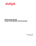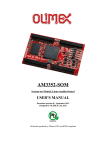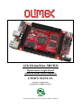
1
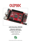
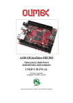
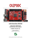
A20-OLinuXino-MICRO Open-source single-board Android/Linux mini-computer USER’S MANUAL Revision C, August 2013 Designed by OLIMEX Ltd, 2013 All boards produced by Olimex LTD are ROHS compliant OLIMEX© 2013 A20-OLinuXino-MICRO user's manual DISCLAIMER © 2013 Olimex Ltd. Olimex®, logo and combinations thereof, are registered trademarks of Olimex Ltd. Other product names may be trademarks of others and the rights belong to their respective owners. The information in this document is provided in connection with Olimex products. No license, express or implied or otherwise, to any intellectual property right is granted by this document or in connection with the sale of Olimex products. This work is licensed under the Creative Commons Attribution-ShareAlike 3.0 Unported License. To view a copy of this license, visit http://www.creativecommons.org/licenses/by-sa/3.0/. This hardware design by Olimex LTD is licensed under a Creative Commons Attribution-ShareAlike 3.0 Unported License. The software is released under GPL. It is possible that the pictures in this manual differ from the latest revision of the board. The product described in this document is subject to continuous development and improvements. All particulars of the product and its use contained in this document are given by OLIMEX in good faith. However all warranties implied or expressed including but not limited to implied warranties of merchantability or fitness for purpose are excluded. This document is intended only to assist the reader in the use of the product. OLIMEX Ltd. shall not be liable for any loss or damage arising from the use of any information in this document or any error or omission in such information or any incorrect use of the product. This evaluation board/kit is intended for use for engineering development, demonstration, or evaluation purposes only and is not considered by OLIMEX to be a finished end-product fit for general consumer use. Persons handling the product must have electronics training and observe good engineering practice standards. As such, the goods being provided are not intended to be complete in terms of required design-, marketing-, and/or manufacturing-related protective considerations, including product safety and environmental measures typically found in end products that incorporate such semiconductor components or circuit boards. Olimex currently deals with a variety of customers for products, and therefore our arrangement with the user is not exclusive. Olimex assumes no liability for applications assistance, customer product design, software performance, or infringement of patents or services described herein. THERE IS NO WARRANTY FOR THE DESIGN MATERIALS AND THE COMPONENTS USED TO CREATE A20-OLINUXINO-MICRO. THEY ARE CONSIDERED SUITABLE ONLY FOR A20-OLINUXINO-MICRO. Page 2 of 40 OLIMEX© 2013 A20-OLinuXino-MICRO user's manual Table of Contents DISCLAIMER............................................................................................................. 2 CHAPTER 1: OVERVIEW........................................................................................5 1. Introduction to the chapter.......................................................................................................5 1.1 Features.....................................................................................................................................5 1.2 Target market and purpose of the board...............................................................................6 1.3 Board variants..........................................................................................................................6 1.4 Board version used in the manual..........................................................................................6 1.5 Organization.............................................................................................................................6 CHAPTER 2: SETTING UP THE OLINUXINO BOARD.....................................8 2. Introduction to the chapter.......................................................................................................8 2.1 Electrostatic warning...............................................................................................................8 2.2 Requirements........................................................................................................................... 8 2.3 Powering the board..................................................................................................................9 2.4 Button functions and NAND image restore in Android..................................................... 10 2.5 Prebuilt software....................................................................................................................10 2.6 Software support....................................................................................................................10 CHAPTER 3: A20-OLinuXino-MICRO BOARD DESCRIPTION..................... 11 3. Introduction to the chapter..................................................................................................... 11 3.1 Layout (top view)................................................................................................................... 11 3.2 Layout (bottom view).............................................................................................................12 CHAPTER 4: THE ALLWINNER A20 MICROCONTROLLER.......................13 4. Introduction to the chapter.....................................................................................................13 4.1 The microcontroller...............................................................................................................13 4.2 Block diagram........................................................................................................................ 14 CHAPTER 5: CONTROL CIRCUITY................................................................... 15 5. Introduction to the chapter.....................................................................................................15 5.1 Reset........................................................................................................................................15 5.2 Clocks......................................................................................................................................15 5.3 Power supply circuit.............................................................................................................. 15 CHAPTER 6: CONNECTORS AND PINOUT......................................................16 6. Introduction to the chapter.....................................................................................................16 6.1 Communication with the A20............................................................................................... 16 6.1.1 USB-OTG communication (NAND firmware repair/update)..................................................................16 6.1.2 UART0, UEXT1, UEXT2 interface............................................................................................................18 6.2 SD card connectors................................................................................................................19 6.2.1 SD/MMC1 slot..............................................................................................................................................19 6.2.2 SD/MMC slot................................................................................................................................................20 6.3 PWR jack................................................................................................................................22 6.4 MIC_IN & HEADPHONES connectors..............................................................................22 Page 3 of 40 OLIMEX© 2013 A20-OLinuXino-MICRO user's manual 6.6 USB_OTG connector.............................................................................................................23 6.7 USB_HOST connector...........................................................................................................24 6.9 Ethernet.................................................................................................................................. 25 6.10 HDMI connector.................................................................................................................. 27 6.11 SATA connector and power.................................................................................................28 6.12 GPIO-1 (General Purpose Input/Output) 14pin connector** ........................................29 6.13 GPIO-2 (General Purpose Input/Output) 40pin connector ............................................29 6.14 GPIO-3 (General Purpose Input/Output) 10pin connector.............................................31 6.15 LCD_CON 40pin connector ...............................................................................................31 6.16 Jumper description..............................................................................................................33 6.17 Additional hardware components...................................................................................... 33 CHAPTER 7: SCHEMATICS..................................................................................35 7. Introduction to the chapter.....................................................................................................35 7.1 Eagle schematic......................................................................................................................35 7.2 Physical dimensions...............................................................................................................36 CHAPTER 8: REVISION HISTORY AND SUPPORT........................................ 37 8. Introduction to the chapter.....................................................................................................37 8.1 Document revision................................................................................................................. 37 8.2 Board revision........................................................................................................................ 37 8.3 Useful web links and purchase codes...................................................................................38 8.4 Product support..................................................................................................................... 40 Page 4 of 40 OLIMEX© 2013 A20-OLinuXino-MICRO user's manual CHAPTER 1: OVERVIEW 1. Introduction to the chapter Thank you for choosing this OLinuXino single board computer from Olimex! This document provides a user’s guide for the Olimex A20-OLinuXino board. As an overview, this chapter gives the scope of this document and lists the board’s features. The document’s organization is then detailed. The A20-OLinuXino-MICRO development board enables code development of applications running on the A20 microcontroller, manufactured by Allwinner Technology from China. OLinuXino is an open-source, open-hardware project and all documentation is available to the customer. 1.1 Features The board has the following set of features (note about the difference between the two versions of the board): • • • • • • • • • • • • • • • • • • • • • • • • • A20 Cortex-A7 dual-core ARM Cortex-A7 CPU and dual-core Mali 400 GPU 1GB DDR3 RAM memory 4GB NAND FLASH memory (available only on the 4GB version of the board) Android already loaded on the NAND (available only on the 4GB version of the board) SATA connector with 5V SATA power jack Built-in FullHD support (1080p) 2 x USB High-speed host with power control and current limiter USB-OTG with power control and current limiter HDMI output with ESD protectors VGA output on 6-pin 1.25mm (0.05'') step connector 100MBit native Ethernet Battery connector with battery-charging capabilities Audio headphones output on connector Microphone input on connector 2 x UEXT connectors LCD connector compatible with with 4.3'', 7.0'', 10.1" LCD modules from Olimex 160 GPIOs on three GPIO connectors MicroSD card connector SD/MMC card connector DEBUG-UART connector for console debug with USB-SERIAL-CABLE-F GPIO LED Battery charge status LED Power LED 2KB EEPROM for MAC address storage and more 10 BUTTONS with ANDROID functionality + RESET button Page 5 of 40 OLIMEX© 2013 A20-OLinuXino-MICRO user's manual • 4 mount holes • 6-16V input power supply, noise immune design • PCB dimensions: (5600 x 3250) mils ~ (142.24 x 82.55) mm 1.2 Target market and purpose of the board The boards from the OLinuXino family are easy to setup and powerful. It is possible to use them in almost any application as a host board. They are suitable for embedded programming enthusiasts, Linux and Android gadget fans (they can just use the board as a media center or fully functional Linux-PC, for instance) and also professionals (since its low cost makes it very good solution for application-orientated embedded systems). The main usage of the board is software embedded development without the urge of understanding perfectly the hardware. The strong points of the boards are the processor speed, the small form factor and the low price-toproductivity ratio. Customers have full access to the technical documentation of the board. The software is released under General Purpose License and the board is considered open-hardware – all schematics and board design files are available to the customer under the Creative Commons AttributionShareAlike 3.0 Unported License. 1.3 Board variants There are two major board variants named: A20-OLinuXino-MICRO-4GB and A20-OLinuXinoMICRO. The 4GB version has a built-in NAND memory suitable for the storage of an operating system without the need of a SD card. The 4GB version comes with already programmed Android 4.2.2 image. The other Olimex boards with close characteristics are the ones with A13 and A10/A10s microcontrollers. The A13 boards feature a generation older processor but since they have been longer on the market they have better Linux and Android support. The A10/A10s boards feature single (than A20) processor core but they are more energy efficient making them better choices for handheld devices and devices requiring power efficiency. Additional Android and Linux support and features are added overtime. The Linux support is a work in progress and you should not expect full Linux support after the initial volume of such boards have become available on the market. If you are in a hurry consider the older OLinuXino designs (which have almost everything supported, have examples available and so on). 1.4 Board version used in the manual Revision E boards and resources were used while writing this document. It is possible that they are outdated so it is always recommended to download the latest sources from the GitHub page of the board. 1.5 Organization Each section in this document covers a separate topic, organized as follow: Page 6 of 40 OLIMEX© 2013 – – – – – – – – A20-OLinuXino-MICRO user's manual Chapter 1 is an overview of the board usage and features Chapter 2 provides a guide for quickly setting up the board and software notes Chapter 3 contains the general board diagram and layout Chapter 4 describes the component that is the heart of the board: the A20 – Allwinner processor Chapter 5 is an explanation of the control circuitry associated with the microcontroller Chapter 6 covers the connector pinout, peripherals and jumper description Chapter 7 provides the schematics and the dimensions of the board Chapter 8 contains the revision history, useful links and support information Page 7 of 40 OLIMEX© 2013 A20-OLinuXino-MICRO user's manual CHAPTER 2: SETTING UP THE OLINUXINO BOARD 2. Introduction to the chapter This section helps you set up the OLinuXino development board for the first time. Please consider first the electrostatic warning to avoid damaging the board, then discover the hardware and software required to operate the board. The procedure to power up the board is given, and a description of the default board behavior is detailed. 2.1 Electrostatic warning OLinuXino is shipped in a protective anti-static package. The board must not be exposed to high electrostatic potentials. A grounding strap or similar protective device should be worn when handling the board. Avoid touching the component pins or any other metallic element. 2.2 Requirements In order to set up the A20-OLinuXino-MICRO optimally one or more additional items may be used. They might be generally placed in three categories: Required - items that are needed in order to achieve minimum functionality; Recommended – items that is good to have in order to be able to interact with the most important of the features of the board; Additional – items that provide access to additional features or expand the features of the board. Required items: - USB type A to USB mini cable – to connect to a personal computer; used for powering the board and uploading new Android image to the NAND memory (if your board has 4GB NAND) - Input device – either a mouse/keyboard or touchscreen LCD - Output device – either HDMI cable + HDMI-enabled monitor/screen/projector; or OLIMEX LCD (TS) display + 40-pin CABLE-IDC40-15cm; or USB-SERIAL-CABLE-F + personal computer (for Linux and/or Android debugging) - SD card with compatible image – if you have the board version with NO additional NAND memory you will need it to use one of the images available. Recommended items: - External USB hub – to split the USB_HOST mounted on the board; you need that to connect more USB devices - External power supply unit – 6-16V DC, 5W required (10V @ 0.5A) – for optimal power - USB-SERIAL-CABLE-F – for Android/Linux debugging on UART0 - CABLE-IDC40-15cm – cable used for LCD_CON ↔ Olimex LCD display Additional items include: - Audio device for HEADPHONES jack - Ethernet cable for wired Ethernet Page 8 of 40 OLIMEX© 2013 A20-OLinuXino-MICRO user's manual - A number of extension modules that can add functionality or interface to the board on the UEXT connector; these can be explored here: https://www.olimex.com/Products/Modules/ Some of the above-suggested items can be purchased by Olimex, for instance: SY0612E – reliable power supply adapter 50Hz (for EU) 12V/0.5A for A20-OLinuXino-MICRO SY0612E-CHINA – cheaper power supply adapter 50Hz (for EU) 12V/0.5A for A20-OLinuXinoMICRO A20-Android-SD – a tested class 10 micro SD card with the latest (by the time of leaving the Olimex facilities) official Android release A20-Debian-SD – a tested class 10 micro SD card with the latest (by the time of leaving Olimex facilities) official Debian Linux release USB-SERIAL-CABLE-F - USB serial console cable female USB-MINI-CABLE – standard USB type A to USB type mini cable CABLE-IDC40-15cm – cable for LCD to LCD_CON connection A13-LCD43TS – low-cost 4.3'' LCD display with touchscreen component - 480 x 272 A13-LCD7 – low-cost 7'' LCD display with optional touchscreen component - 800 x 480 A13-LCD10 – low-cost 10'' LCD display with optional touchscreen component – 1024 x 600 2.3 Powering the board There are three possible ways of powering A20-OLinuXino-MICRO-4GB – via external supply providing 6-16V DC at the power jack, from 5V USB port via USB_OTG connector or from 3.7V Li-Po battery via the LIPO_BAT. Note that the board consumes around 300mA of current at 12V when there are no peripherals connected to the USB hosts, so make sure the power supply is able to provide at least 500mA before plugging. Depending on your preferred way of powering you might need additional hardware. Important: Not all USB ports would be able to provide enough power for the board. The best practice is not to count on the mini USB-OTG as a single power source! The preferred way of powering the board is via the PWR jack with 6-16V DC with a power of 5W (e.g. 6Vx0.8A; 16Vx0.3A). This will make the board fully powered and able to power all the peripherals connected to it. Note that when powering the board from the USB_OTG, the power provided might be insufficient to also power a bigger LCD connected to the LCD_con. However, this power option is capable of driving the board when using external display connected to the HDMI connector. The typical consumption of A20-OLinuXino-MICRO-4GB is between 100mA and 320mA depending on the current load and the power voltage applied. If the board has entered power-down state you can bring it back without restart using the PWR_BUT. The PWR_BUT is also used to start the board when powered from a Li-Po battery on the battery connector. For the European customers we sell two power supply adapters, please check chapter 2.2. We also sell USB OTG to USB type A cables if you lack such. Page 9 of 40 OLIMEX© 2013 A20-OLinuXino-MICRO user's manual The default username/password combination for the default Linux image on the SD card (if purchased) is: root/olimex. Note that it is normal that when the board is powered some integrated circuits might appear hotter than others. This is perfectly normal for some chips – for instance – voltage regulators and the main processor. 2.4 Button functions and NAND image restore in Android The bellow three buttons usually are supported under both Android and Debian: PWR_BUT – used to perform software turn off, software turn on; used to turn on board when powered by battery – has to be held down for at least 5 seconds to perform each action RESET – used for hardware reset of the board – it is not recommended RECOVERY – used to wake up the board from sleep The following buttons represent functions in the Android (it is possible that not all Android applications take advantage of the buttons, in such case the button would serve no purpose for that application): VOL+ – increases the volume VOL- – lowers the volume MENU – brings up the main menu SEARCH – brings up search feature HOME – shows the home screen; note that HOME is also used to enter bootloader mode for firmware update ESC – used to navigate away of a menu ENTER – to select a choice It is not recommended to disconnect the power supply (either the USB or the power jack) before turning off the Android from the either the menus or by holding PWR_BUT system written on the NAND. 2.5 Prebuilt software The 4GB board-variant comes with Android 4.2.2 ready to use. The default settings of the software are followed. The default image works with HDMI monitor and 7'' display. How we have installed the software? Detailed information might be found in chapter 6.1.1 USBOTG communication (NAND firmware repair/update). 2.6 Software support We maintain Linux and Android images for SD card which might be downloaded for free and modified as the user wishes. The latest images and updates are featured at the wiki article of the device: https://www.olimex.com/wiki/A20-OLinuXino-MICRO. Page 10 of 40 OLIMEX© 2013 A20-OLinuXino-MICRO user's manual CHAPTER 3: A20-OLinuXino-MICRO BOARD DESCRIPTION 3. Introduction to the chapter Here you get acquainted with the main parts of the board. Note the names used on the board might differ from the names used below to describe them. For the actual names check the A20OLinuXino-MICRO board itself. 3.1 Layout (top view) The picture below shows the initial revision of A20-OLinuXino-MICRO. Please note that the NAND memory is present only in the 4GB version of the board. Page 11 of 40 OLIMEX© 2013 A20-OLinuXino-MICRO user's manual 3.2 Layout (bottom view) At the bottom of the board there are mainly buttons and the large SD/MMC connector. Page 12 of 40 OLIMEX© 2013 A20-OLinuXino-MICRO user's manual CHAPTER 4: THE ALLWINNER A20 MICROCONTROLLER 4. Introduction to the chapter In this chapter is located the information about the heart of OLinuXino – its microcontroller. The information is a modified version of the datasheet provided by its manufacturers. 4.1 The microcontroller CPU ARM® Cortex™-A7 Dual-Core GPU ARM® Mali400MP2 Complies with OpenGL ES 2.0/1.1 VIDEO HD H.264 2160p video decoding Multi-format FHD video decoding, including Mpeg1/2, Mpeg4 SP/ASP GMC, H.263, H.264, VP6/8, AVS jizun, Jpeg/Mjpeg, etc. H.264 High Profile 1080p@30fps or 720p@60fps encoding 3840x1080@30fps 3D decoding, BD/SBS/TAB/FP supported Complies with RTSP, HTTP,HLS,RTMP,MMS streaming media protocols DISPLAY Supports multi-channel HD display Integrated HDMI 1.4 transmitter with HDCP support CPU/RGB/LVDS LCD interface Supports CVBS/YPbPr/VGA Integrated TV decoder CAMERA Integrated parallel 8-bit I/F YUV sensor Integrated 24-bit parallel YUV 444 I/F Supports 5M CMOS sensor Supports dual sensors MEMORY DDR2/DDR3/DDR3L controller Page 13 of 40 OLIMEX© 2013 A20-OLinuXino-MICRO user's manual NAND Flash controller with 64-bit ECC AUDIO Integrated HI-FI 100dB Audio Codec Dual analog mic amplifiers More information can be found on Allwinner's web site at the following web-address: http://www.allwinnertech.com/en/product/A20.html 4.2 Block diagram The block diagram is taken from Allwinner's web-site. Page 14 of 40 OLIMEX© 2013 A20-OLinuXino-MICRO user's manual CHAPTER 5: CONTROL CIRCUITY 5. Introduction to the chapter Here you can find information about reset circuit and quartz crystals locations, the power supply circuit is discussed. 5.1 Reset The board has hardware reset controlled by the AXP209 power system management IC. The board should be turned off the standard OS menu (that might be invoked by holding POWER button or “poweroff” command under Debian) and after the choice is confirmed it is safe to be disconnected from the power supply unit. 5.2 Clocks 25 MHz quartz crystal Q1 is connected to pins X1 and X2 of the A20 microcontroller. 32 768 Hz (RTC) quartz crystal Q2 is found at pins F1 and F2 of the A20 microcontroller. 24 MHz quartz crystal Q3 is found at pins N22 and N23 of the A20 microcontroller. 5.3 Power supply circuit The power supply is handled mainly by AXP209 power management system, an Allwinner chip that goes together with the A20 processor. It is mounted on the board but since it is relatively hard to find we also sell it separately. The power supply circuit of A20-OLinuXino-MICRO requires input supply of 6-16V. The minimum wattage is 5W, and this threshold may raise if using a lot of devices on the USB-HOST (via external hub), a lot of GPIOs and the LCD_CON. Page 15 of 40 OLIMEX© 2013 A20-OLinuXino-MICRO user's manual CHAPTER 6: CONNECTORS AND PINOUT 6. Introduction to the chapter In this chapter are presented the connectors that can be found on the board all together with their pinout and notes about them. Jumpers functions are described. Notes and info on specific peripherals are presented. Notes regarding the interfaces are given. 6.1 Communication with the A20 The more direct communication methods include connection via the bootloader and via the serial interface. The chip has a built-in bootloader for communication with computer systems via a USB cable – suitable only for connection with PhoenixSuit program for firmware update. There is a second option to connect to the board which is the male UART0 connector capable of delivering some information on the COM port of your computer – and then use your favorite terminal program (puTTy, teraterm, etc) to receive the data/send commands. You can use USB-SERIAL-CABLE-F with the UART0 interface allowing you to connect to an USB port. The more indirect ways of communicating with the board are via peripheral devices – mouse and keyboard, via a touch screen LCD that is connected on LCD_CON connector and others. 6.1.1 USB-OTG communication (NAND firmware repair/update) The main way of changing the firmware image located on the NAND of A20-OLinuXino-MICRO4GB is via the USB-OTG connector. We have configured an Android image with settings suitable for A20-OLinuXino-MICRO. Then using PhoenixSuit tools we uploaded the image to the board via the USB OTG. The image is available for users to try and tweak the settings. The images can be downloaded from the wiki article at: https://www.olimex.com/wiki/A20-OLinuXino-MICRO. The board variant without NAND needs an SD card with bootable OS – Android or Linux. There are ready images available for download at the above-linked A20 wiki article. To repair the image on NAND re-upload it following these easy steps: 1. Install and run PhoenixSuit (can be found in the wiki article for A20). 2. Go to firmware tab of the program and point to a valid Android image (the latest official one may also be downloaded from the A20 wiki article). 3. Disconnect the power supply and USB cable from the A20 board. 4. Press and hold RECOVERY button, apply power supply (6-16)V, release RECOVERY button. 5. Connect USB cable to the mini USB connector Page 16 of 40 OLIMEX© 2013 A20-OLinuXino-MICRO user's manual 6. You will be asked for drivers for the bootloader. Navigate to the folder where you extracted the PhoenixSuit and install the drivers from the respective executables (or manually point the installer to the drivers folder in the PhoenixSuit installation path). 7. PhoenixSuit will detect the board and would ask for the method of writing the image. Choose method of writing the image and confirm your wish to write the image. 8. Wait till upgrade succeeds as shown below: There are different flavors of the Android and Linux distributions depending on whether you want to use 50Hz HDMI or 60Hz HDMI or 7'' display or 10'' display etc. You might need to change the configuration files inside (depending on your current setup) the SD card (explore the SD card and make sure the correct, corresponding your needs, “script.bin” is placed in the first SD card partition; overwrite the original one). Those images , the software required and further instructions might be found at the wiki page: https://www.olimex.com/wiki/A20-OLinuXino-MICRO. Page 17 of 40 OLIMEX© 2013 A20-OLinuXino-MICRO user's manual 6.1.2 UART0, UEXT1, UEXT2 interface The UART0 might be used for UART communication by default. It is typically used for serial/terminal debug. The UEXTs are typically used for connecting additional modules. Note that by default only UART0 is defined as a port suitable for serial debug. You can use our USB-SERIAL-CABLE-F for debugging. UEXT1 and UEXT2 are NOT defined by default. Consider table below when connecting the USB-SERIAL-CABLE-F according to the wire color code. The RX line of the cable (GREEN wire) should go to TX line of the target board; the TX line of the cable (RED wire) should go to the RX line of the target board. The BLUE wire should go to the target's GND line. UART0 Pin # Signal name Processor pin 1 3.3V - 2 UART0-TX A7 3 UART0-RX B7 4 GND UEXT1 Pin # Signal name Pin # Signal name 1 3.3V 6 TWI2-SDA 2 GND 7 SPI2-MISO 3 UART6-TX 8 SPI2-MOSI 4 UART6-RX 9 SPI2-CLK 5 TWI2-SCK 10 SPI2-CS0 UEXT2 Pin # Signal name Pin # Signal name 1 3.3V 6 TWI1-SDA 2 GND 7 SPI1-MISO 3 UART7-TX 8 SPI1-MOSI 4 UART7-RX 9 SPI1-CLK 5 TWI1-SCK 10 SPI1-CS0 The UEXT connectors are used as an interface for the Olimex's UEXT modules (usually boards Page 18 of 40 OLIMEX© 2013 A20-OLinuXino-MICRO user's manual with MOD- prefix in their commercial names). For more information on UEXT please visit: https://www.olimex.com/Products/Modules/UEXT/resources/UEXT.pdf 6.2 SD card connectors There are two SD card connectors on this A20 board. The now common microSD card connector is located on the top of the board, near the audio in/out connectors. Note that by default only the micro SD card slot might be used for booting the OS. However, due to popular demand, there is also an SD/MMC card connector located on the bottom of the board. Both SD slots might be used simultaneously – there is no data multiplexing lines. For instance – one of them might be used for booting the OS, the other – for saving data. As a general precaution be careful with the SD cards you purchase. There is a big percentage of fake cards due to the low effort required to counterfeit popular brands and the big demand for SD cards worldwide. When in doubt – try the same operation with another card from another brand. Olimex sells microSD cards with Linux or Android images, that have been tested – please refer to chapter “2.2 Requirements”. Of course, if you already have a large enough microSD card you can download the official Linux image from the wiki pages: https://www.olimex.com/wiki/A20OLinuXino-MICRO. When removing the card, please make sure that you release it from the connector by pushing and NOT by pulling the card directly (this can damage both the connector and the microSD card). 6.2.1 SD/MMC1 slot The schematic related to the SD/MMC1 (microSD connector) is shown below: Page 19 of 40 OLIMEX© 2013 A20-OLinuXino-MICRO user's manual SD/MMC1 slot is the “smaller” microSD card slot, located on the top of the board. This slot is typically used for booting the OS, due to the larger capacities of the microSD cards (compared to SD or MMC cards). It is suggested to have an SD card with a proper Linux/Android image especially if you have ordered a version of the board without NAND memory. It is also recommended to use Class 10 (10MByte/sec) card for faster read/write operations, lower class cards (especially higher capacity ones) might slow down the whole system. microSD card connector Pin # Connector signal name Wire name (processor pin) 1 DAT2/RES SD0-D2 (K19) 2 CD/DAT3/CS SD0-D3 (K20) 3 CMD/DI - 4 VDD - 5 CLK/SCLK SD0-CLK(L20) 6 VSS2 - 7 DAT0/DO SD0-D0(M19) 8 DAT1/RES SD0-D1(M20) 6.2.2 SD/MMC slot The schematic related to the SD/MMC1 (SD/MMC connector) is shown below: Page 20 of 40 OLIMEX© 2013 A20-OLinuXino-MICRO user's manual The SD/MMC2 slot is located on the back of the PCB and works with the “larger” SD and MMC cards. The connector was mounted to to popular demand. Note that by default this connector is not suitable for booting OS. Such support is possible but not implemented in the official software releases. SD/MMC card connector Pin # Connector signal name Wire name (processor pin) 1 CD/DAT3/CS SDC3-D3 (B16) 2 CMD/DI SDC3-CMD (A18) 3 VSS1 - 4 VDD - 5 CLK/SCLK SDC3-CLK (B18) 6 VSS2 - 7 DAT0/DO SDC1-D0 (A17) 8 DAT1/RES SDC1-D1 (B17) 9 DAT2/RES SDC1-D2 (A16) Additionally, there are the WP and CP switches that are responsible, respectively, for sensing whether the card is locked for reading and whether there is a card inserted. Page 21 of 40 OLIMEX© 2013 A20-OLinuXino-MICRO user's manual 6.3 PWR jack The power jack used is the typical 2.5mm one used by Olimex in most of our products. You should provide 6 to 16 volts direct current and the required current may vary depending on the peripherals connected to the board. The power supply you use should be capable of providing at least 500mA of current. Pin # Signal name 1 Power input 2 GND More info about the power supply can be found in chapter 5 of this manual. 6.4 MIC_IN & HEADPHONES connectors The part of the schematic related to those connectors is listed below: Page 22 of 40 OLIMEX© 2013 A20-OLinuXino-MICRO user's manual Standard MIC_IN jack is mounted for audio input to the board. Note that it is a single channel MIC_IN. The MIC_IN is a mono input. MIC_IN connector Pin # Signal name Processor pin 2 MICIN AC20 3 MICIN AC20 5 GND - The socket can interface standard 3.5 mm phone connector (also known stereo plug or audio plug). Headphones connector Pin # Signal name Processor pin 2 HPOUTL Y19 3 HPOUTR W19 5 HPCOM (GND) AA19, AA20 The connector can interface standard 3.5 mm phone connector (also known stereo plug or audio plug). 6.6 USB_OTG connector The part of the schematic related to the USB_OTG is shown below: The USB_OTG features Low Loss Power Distribution Switch SY6280 which protects the board in case the devices you have plugged to the USB_OTG attempt to draw more current than 523mA combined. The maximum current available on the 5V USB_OTG is exactly 523mA. The SY6280 responsible for the USB_OTG is enabled by USB0-DRV (processor pin C12), thus the Page 23 of 40 OLIMEX© 2013 A20-OLinuXino-MICRO user's manual USB_OTG is also controlled by the same signal. USB_OTG connector Pin # Signal name Processor pin 1 +5V_OTG_PWR - 2 UDM0 N20 3 UDP0 N21 4 USB0-IDDET B5 5 GND - The connector case is also grounded. 6.7 USB_HOST connector The part of the schematic related to the USB_HOST connector is listed below: The USB_HOST connector features two levels – called USB1 and USB2 in the schematic. The connector is situated between the USB_OTG and the HDMI connector. Each of slots them features a Low Loss Power Distribution Switch SY6280 which protects the board in case the devices you have plugged to each level USB_HOST try to draw more current than 523mA combined. The maximum current available on each slot of the 5V USB_HOST is exactly 523mA. The SY6280 responsible for the USB1 is enabled by USB0-DRV1 (processor pin A4), thus the USB_OTG is also controlled by the same signal. The SY6280 responsible for the USB2 is enabled by USB0-DRV2 (processor pin A5), thus the USB_OTG is also controlled by the same signal. Page 24 of 40 OLIMEX© 2013 A20-OLinuXino-MICRO user's manual USB_HOST two-level connector Pin # Signal name Processor pin Pin # Signal name Processor pin 1.1 5V Connected to SY628 2.1 5V Connected to SY628 1.2 UDM1 P20 2.2 UDM2 R20 1.3 UDP1 P21 2.3 UDP2 R21 1.4 GND - 2.4 GND - The GND is common for both levels of the USB_HOST. 6.9 Ethernet The LAN connectivity is handled by Realtek's RTL8201CP. Some of the features of this 10/100Mbit controller are: - 10/100Mbps operation - Full/half duplex operation - Supports auto crossover detection - Adaptive equalization - IEEE 802.3/802.3u compliant - Supports IEEE 802.3u clause 28; 1.8V - Operation with 3.3V IO signal tolerance and much more The Ethernet connector is grounded according to the standard (check GND1 and GND2 lines on the schematics) The EEPROM memory may be used to store the MAC address. Important: In some Debian images it is possible that the Ethernet doesn't get auto-detected during boot-up. This is done on purpose because if there is auto-detection enabled and you don't want to use the Ethernet connector or you have forgotten to plug a cable the start-up would be greatly delayed. This might be problem in the first start-up to users counting only on SSH connection. You can enable the Ethernet after a successful boot-up with: ifconfing -a dhclient eth#(as seen after after the ifconfing command) Important: You can configure static/DHCP-given IP addresses in /etc/network/interfaces Page 25 of 40 OLIMEX© 2013 A20-OLinuXino-MICRO user's manual Page 26 of 40 OLIMEX© 2013 A20-OLinuXino-MICRO user's manual Ethernet Pin # Signal name 1 TD+ 2 TD- 3 VDD 4 NC 5 NC 6 VDD 7 RD+ 8 RD- LED Color Usage Right Green Link status Left Yellow Activity status 6.10 HDMI connector The part of the schematic that describes the HDMI module is shown below: Note that there are different Linux images depending whether the HDMI TV works at 50Hz or 60Hz refresh rate. If you board runs Android there is a specific option to set the appropriate HDMI Page 27 of 40 OLIMEX© 2013 A20-OLinuXino-MICRO user's manual output. HDMI connector Pin # Signal name Processor pin 1 HTX2P T23 2 GND 3 Pin # Signal name Processor pin 11 GND - - 12 HTXCN W22 HTX2N T22 13 HCEC P23 4 HTX1P U23 14 NA* NA 5 GND - 15 HSCL R23 6 HTX1N U22 16 HSDA R22 7 HTX0P U23 17 GND - 8 GND - 18 +5V - 9 HTX0N U22 19 HHPD P22 10 HTXCP W23 *Pin 14 of the HDMI is not mandatory. In HDMI 1.0-1.3c it is reserved pin; in HDMI 1.4+ it is optional. 6.11 SATA connector and power The part of the schematic describing the SATA module is shown below: SATA connector Pin # Signal name Processor pin 1 GND - 2 SATA-TXP T20 3 SATA-TXM T21 4 GND - 5 SATA-RXM U21 6 SATA-RXP U20 7 GND - Page 28 of 40 OLIMEX© 2013 A20-OLinuXino-MICRO user's manual 6.12 GPIO-1 (General Purpose Input/Output) 14pin connector** The GPIO-1 plastic connector has 14 pins. The signal layout is described below: GPIO-1 connector Pin # Signal name Processor pin Pin # Signal name Processor pin 1 +5V - 2 GND - 3 +3.3V - 4 GND - 5 PG0 F20 6 VOL+_BUT AB23*** 7 PG1 E21 8 VOL-_BUT AB23*** 9 PG2 E20 10 MENU_BUT AB23*** 11 PG3 D21 12 SEARCH_BUT AB23*** 13 PG4 D20 14 HOME_BUT AB23*** 15 PG5 C21 16 ESC_BUT AB23*** 17 PG6 E19 18 ENTER_BUT AB23*** 19 PG7 C20 20 TVOUT3 AB17 21 PG8 D19 22 TVIN0 AC18 23 PG9 C19 24 TVIN1 AB18 25 PG10 D18 26 TVIN2 AA17 27 PG11 C18 28 TVIN3 Y17 29 VGA_HSYNC AB9* 30 LINEINR AB21 31 VGA_VSYNC AC9* 32 LINEINL AB20 33 VGA-G AC16* 34 FMINR Y21 35 VGA-B AB16* 36 FMINL Y20 37 VGA-R AC17* 38 MIC1OUTP AC22 39 LRADC1 AB22* 40 MIC1OUTN AC23 *Signals marked with * are multiplexed with either a peripheral device or another connector. Ensure that the multiplexing is handled properly on software and/or hardware level (else there would probably occur wrong levels, loss of data, etc). **It was erroneously named GPIO-4 in the first release of the board. ***All Android buttons are connected to an ADC (LRADC) that uses a divider to determine which button is pressed. The yellow part of the table shows all the signals shared with the 6-pin VGA connector. 6.13 GPIO-2 (General Purpose Input/Output) 40pin connector The GPIO pins are led out on a separate 40pin connecter. They allow the user to attach additional hardware, check readings or perform hardware debug. The GPIO-2 connector numbers are printed at the bottom of the board for your convenience. Page 29 of 40 OLIMEX© 2013 A20-OLinuXino-MICRO user's manual GPIO-2 connector GPIO pin# Signal name Processor pin# GPIO pin# Signal name Processor pin# 1 5V - 2 GND - 3 3.3V - 4 GND - 5 TWI0-SCK A15 6 PE0 E23 7 TWI0-SDA B15 8 PE1 E22 9 PI0 A20 10 PE2 D23 11 PI1 B20 12 PE3 D22 13 PI2 A19 14 PE4 C23 15 PI3 B19 16 PE5 C22 17 PI10 C17 18 PE6 B23 19 PI11 D17 20 PE7 B22 21 PC3/NCE1 L22* 22 PE8 A23 23 PC7/NRB1 J22* 24 PE9 A22 25 PC16 M21 26 PE10 B21 27 PC17 F23 28 PE11 A21 29 PC18 F22 30 PI14 C15 31 PC23 G19 32 PI15 D15 33 PC24/NQS F21* 34 UART0-RX B7* 35 GPIO1 - 36 UART0-TX A7* 37 GPIO2 - 38 NMI_N F5 39 GPIO3 - 40 RESET_N C14 Signals marked with * are multiplexed with either a peripheral device or another connector. Ensure that the multiplexing is handled properly on software and/or hardware level (else there would probably occur wrong levels, loss of data, etc). Page 30 of 40 OLIMEX© 2013 A20-OLinuXino-MICRO user's manual 6.14 GPIO-3 (General Purpose Input/Output) 10pin connector GPIO-3 connector features the signals of AXP152 on a convenient header. The signals available might be used to implement power controls on the board – for instance – turning off the device at specific voltage level or GPIO-3 connector GPIO pin# Signal name Processor pin# GPIO pin# Signal name Processor pin# 1 5V - 2 GND - 3 3.3V - 4 GND - 5 PH0 A6 6 PB3 B14 7 PH2/LED C6 8 PB4 A13 9 PH7 B4 10 PB5 B13 11 PH9 D4 12 PB6 A12 13 PH10 A3 14 PB7 B12 15 PH11/SDC3-DET# B3* 16 PB8/SATA-PWR-EN A11 17 PH12 C3 18 PB10 C11 19 PH13 A2 20 PB11 C10 21 PH14 B2 22 PB12 C9 23 PH15 A1 24 PB13 B11 25 PH16 B1 26 PB14 A10 27 PH17 C1 28 PB15 B10 29 PH18 C2 30 PB16 A9 31 PH19 D1 32 PB17 B9 33 PH20 D2 34 PH24 E3 35 PH21 D3 36 PH25 E4 37 PH22 E1 38 PH26 F3 39 PH23 E2 40 PH27 F4 Signals marked with * are multiplexed with either a peripheral device or another connector. Ensure that the multiplexing is handled properly on software and/or hardware level (else there would probably occur wrong levels, loss of data, etc). 6.15 LCD_CON 40pin connector The LCD_CON pins are led out on a separate 40pin connecter for the ease of connecting an LCD. We have tested the ability of the board to interact with such a display. They allow the user to attach additional hardware, check readings or perform hardware debug. Important: you need additional 40PIN ribbon cable to connect an Olimex display and the LCD_CON. Page 31 of 40 OLIMEX© 2013 A20-OLinuXino-MICRO user's manual LCD_CON connector GPIO pin# Signal name Processor pin GPIO pin# Signal name Processor pin 1 +5V - 2 GND - 3 +3.3V - 4 GND - 5 LCD_D16 Y12 6 LCD_D17 AA12 7 LCD_D18 Y11 8 LCD_D19 AA11 9 LCD_D20 Y10 10 LCD_D21 AA10 11 LCD_D22 AB12 12 LCD_D23 AC10 13 LCD_D8 AB11 14 LCD_D9 AC11 15 LCD_D10 Y15 16 LCD_D11 AA15 17 LCD_D12 Y14 18 LCD_D13 AA14 19 LCD_D14 Y13 20 LCD_D15 AA13 21 LCD_D0 AB15 22 LCD_D1 AC15 23 LCD_D2 AB14 24 LCD_D3 AC14 25 LCD_D4 AB13 26 LCD_D5 AC13 27 LCD_D6 AB12 28 LCD_D7 AC12 29 LCD_HSYNC AB9 30 LCD_VSYNC AC9 31 LCD_CLK Y9 32 LCD_DE AA9 33 PB3 B14 34 PB4 A13 35 LCD_PWR C4 36 PB2/PWM0 A14* 37 TPX1 Y22 38 TPX2 AA22 39 TPY1 Y23 40 TPY2 AA23 Signals marked with * are multiplexed with either a peripheral device or another connector. Ensure that the multiplexing is handled properly on software and/or hardware level (else there would probably occur wrong levels, loss of data, etc). The LCD connector is suitable for a number of Olimex displays and touchscreen panels with different native resolution – the smallest available is the 4.3'' one called A13-LCD43TS with native Page 32 of 40 OLIMEX© 2013 A20-OLinuXino-MICRO user's manual screen resolution of 480x272, through the 7'' one named A13-LCD7 with 800x480, to the 1024x600 10.1'' A13-LCD10. IMPORTANT: To use Android with display or resolution different than HDMI and 1024x600 (default settings) you need to upload new Android image to the board. These images are available here: https://www.olimex.com/wiki/A20-OLinuXino-MICRO (using an operating system - NAND flash). Since the configuration in the Debian images is set to HDMI and 1024x600 (default settings) you would need to change a configuration file in the main partition of the SD card. Detailed information and download locations for the script files might be found at: https://www.olimex.com/wiki/index.php?title=Configuration_of_hardware_in_the_debian_image. 6.16 Jumper description Please note that most the jumpers on the board are SMT type. If you feel insecure of your soldering/cutting technique it is better not to try to adjust the jumpers since it is possible to damage the board. Board jumpers Jumper name Type Default position Function NAND_E PTH UBOOT Changes the functionality of the BOOT/REC button – when in UBOOT position the button is used to enter bootloader mode (to connect via USB_OTG). When in REC VPS- SMT Open Reserved for future use of different types of NAND memories. VPS+ SMT Open Reserved for future use of different types of NAND memories. 6.17 Additional hardware components The components below are mounted on OLinuXino but are not discussed above. They are listed here for completeness: Reset button - used to reset the board 2 x 2Gbytes (2 x 256Mb x 8 bit) DDR3 SDRAM - the exact memory used in the first revisions of the board is Memphis H5TQ2G83CFR-H9C H5TQ2G63BFR 1 x 32Gbytes (4096Mb x 8 bit) NAND FLASH – the exact memory is hynix H27UBG8T2A PWR_LED – lits upon powering the board LED1 – GPIO button Page 33 of 40 OLIMEX© 2013 A20-OLinuXino-MICRO user's manual CHGLED – lits when charging a battery connected to the Li-Po battery connector Page 34 of 40 OLIMEX© 2013 A20-OLinuXino-MICRO user's manual CHAPTER 7: SCHEMATICS 7. Introduction to the chapter In this chapter is located information about the schematics describing logically and physically A20OLinuXino-MICRO. 7.1 Eagle schematic OLinuXino schematics may be found it on the OLinuXino's GitHub repository: https://github.com/OLIMEX/OLINUXINO/tree/master/HARDWARE/A20-OLinuXino-MICRO. You can download the whole repository as .zip without having a GitHub account. Please note that the schematics of A10 (not to be confused with A10s) and A20 boards are the same since the two Allwinner processors are pin-to-pin compatible (drop-in replaceable). Both the 4GB version and the version without NAND of the A20 MICRO share the same set of schematics. We mostly use Eagle by Cad Soft 4.16r2 for designing. However, the files should be compatible with the latest Eagle available. Cad Soft offers a trial version of their software that allows you to inspect schematics and board files (without being able to modify them). This work is licensed under the Creative Commons Attribution-ShareAlike 3.0 Unported License. To view a copy of this license, visit http://creativecommons.org/licenses/by-sa/3.0/. If you are looking for a schematic of an older revision of the board and it isn't available at our web site you may request it by the support e-mail. Page 35 of 40 OLIMEX© 2013 A20-OLinuXino-MICRO user's manual 7.2 Physical dimensions Note that all dimensions are in mils. The three highest elements on the board in order from the tallest to the shortest are: USB_HOST connector – 700mils, capacitors C202 – 650mils, the Ethernet connector – 600mils. The heights listed above include the PCB height. Page 36 of 40 OLIMEX© 2013 A20-OLinuXino-MICRO user's manual CHAPTER 8: REVISION HISTORY AND SUPPORT 8. Introduction to the chapter In this chapter you will find the current and the previous version of the document you are reading. Also the web-page for your device is listed. Be sure to check it after a purchase for the latest available updates and examples. 8.1 Document revision Revision, date Changes Modified page A, 30.08.13 Initial manual release All B, 16.09.13 Quartz values error fixed Updated the board revision changes 15 16 C, 18.09.13 Added new additional products Added more information about the SD card booting 9 43 8.2 Board revision Remember to check the schematics and the board design files to compare the differences. Revision B C Notable changes Initial release of the board 1. 2. 3. 4. 5. Resistor matrix RM23 gets replaced by: R133,R134,R135 Adjusted the package of H5TQ2G63BFR/MEM4G16D3EABG-125 R12 and R15 values changed to 0R NAND_E jumper is changed from PTH to SMD closed 5V_SATA_PWR connector (altogether with 2x2uF) is changed Page 37 of 40 OLIMEX© 2013 C A20-OLinuXino-MICRO user's manual from WF2S to DW02S and placed near the PWR jack instead of original position 6. GPIO-4 is now correctly named GPIO-1 7. There is a signal for the power of of the SATA PB8/SATA-PWR-EN (r136, c216, r138, t1, t137, fet4) 8. A jumper between 5V_E_SATA and 5V_PWR_SATA is added 9. The micro SD card connector is changed D Resistor optimizations E Adjusted and optimized PCB names 8.3 Useful web links and purchase codes The web pages you can visit for more information about your device are: https://www.olimex.com/Products/OLinuXino/A20/A20-OLinuXino-MICRO-4GB/; https://www.olimex.com/Products/OLinuXino/A20/A20-OLinuXino-MICRO/. A place for general questions, FAQ or friendly talk: https://www.olimex.com/forum/. You can get the latest updates on the software at: https://github.com/OLIMEX/OLINUXINO. You may may join our IRC channel #olimex @ freenode.net (http://webchat.freenode.net/? channels=olimex). Page 38 of 40 OLIMEX© 2013 A20-OLinuXino-MICRO user's manual ORDER CODES: A20-OLinuXino-MICRO-4GB – the NAND version of A20-OLinuXino-MICRO with additional 4GB NAND memory (and built-in Android image) A20-OLinuXino-MICRO – the lite version of A20-OLinuXino-MICRO with no external NAND USB-SERIAL-CABLE-F - USB serial console cable female USB-MINI-CABLE – standard USB type A to USB type mini cable SY0612E – reliable power supply adapter 50Hz (for EU) 12V/0.5A for A20-OLinuXino-MICRO SY0612E-CHINA – cheaper power supply adapter 50Hz (for EU) 12V/0.5A for A20-OLinuXinoMICRO A20-Android-SD – a tested class 10 micro SD card with the latest (by the time of leaving the Olimex facilities) official Android release A20-Debian-SD – a tested class 10 micro SD card with the latest (by the time of leaving Olimex facilities) official Debian Linux release A13-LCD43TS – low-cost 4.3'' LCD display with touchscreen component - 480 x 272 A13-LCD7 – low-cost 7'' LCD display with optional touchscreen component - 800 x 480 A13-LCD10 – low-cost 10'' LCD display with optional touchscreen component – 1024 x 600 How to purchase? You can purchase directly from our online shop or from any of our distributors. Note that usually it is faster and cheaper to purchase Olimex products from our distributors. List of confirmed Olimex LTD distributors and resellers: https://www.olimex.com/Distributors. Please visit https://www.olimex.com/ for more info. Page 39 of 40 OLIMEX© 2013 A20-OLinuXino-MICRO user's manual 8.4 Product support For product support, hardware information and error reports mail to: [email protected]. All document or hardware feedback is welcome. Note that we are primarily a hardware company and our software support is limited. Please consider reading the paragraph below about the warranty of Olimex products. All goods are checked before they are sent out. In the unlikely event that goods are faulty, they must be returned, to OLIMEX at the address listed on your order invoice. OLIMEX will not accept goods that have clearly been used more than the amount needed to evaluate their functionality. If the goods are found to be in working condition, and the lack of functionality is a result of lack of knowledge on the customers part, no refund will be made, but the goods will be returned to the user at their expense. All returns must be authorized by an RMA Number. Email [email protected] for authorization number before shipping back any merchandise. Please include your name, phone number and order number in your email request. Returns for any unaffected development board, programmer, tools, and cables permitted within 7 days from the date of receipt of merchandise. After such time, all sales are considered final. Returns of incorrect ordered items are allowed subject to a 10% restocking fee. What is unaffected? If you hooked it to power, you affected it. To be clear, this includes items that have been soldered to, or have had their firmware changed. Because of the nature of the products we deal with (prototyping electronic tools) we cannot allow returns of items that have been programmed, powered up, or otherwise changed post shipment from our warehouse. All returned merchandise must be in its original mint and clean condition. Returns on damaged, scratched, programmed, burnt, or otherwise 'played with' merchandise will not be accepted. All returns must include all the factory accessories which come with the item. This includes any In-Circuit-Serial-Programming cables, anti-static packing, boxes, etc. With your return, enclose your PO#. Also include a brief letter of explanation of why the merchandise is being returned and state your request for either a refund or an exchange. Include the authorization number on this letter, and on the outside of the shipping box. Please note: It is your responsibility to ensure that returned goods reach us. Please use a reliable form of shipping. If we do not receive your package we will not be held liable. Shipping and handling charges are not refundable. We are not responsible for any shipping charges of merchandise being returned to us or returning working items to you. The full text might be found at https://www.olimex.com/wiki/GTC#Warranty for future reference. Page 40 of 40