1
SystemCrafter SC
User Manual
Version 3.0.0
SystemCrafter, SystemCrafter SC, “Bringing Hardware And Software Together”, and the
logos shown above are trademarks of SystemCrafter Ltd.
All other trademarks are the property of their respective owners.
SystemCrafter Ltd does not assume any responsibility arising out of the use of any
information described in this document; nor does it convey any license of its rights or the
rights of others. SystemCrafter Ltd reserves the right to make changes to its products at any
time. SystemCrafter Ltd will not assume any responsibility for information described in this
document. SystemCrafter Ltd provides all information “as is”. By providing information
SystemCrafter Ltd makes no representation that its use is free from any claims of
infringement. You are responsible for obtaining any rights you may require. SystemCrafter
Ltd expressly disclaims any warranty whatsoever with respect to information used from this
document, including but not limited to any warranties or representations that the information
is free from infringement, as well as any implied warranties of merchantability or fitness for a
particular purpose.
SystemCrafter Ltd assumes no obligations to correct any errors
contained in this document, or to advise any user of any correction. SystemCrafter Ltd will
not assume any liability for the accuracy or correctness of any support supplied to any user.
SystemCrafter Ltd products are not intended for use in safety or life critical applications. Any
use in such applications is prohibited.
The contents of this document are owned and copyrighted by SystemCrafter Ltd. © 20042007 SystemCrafter Ltd, All Rights Reserved. Except as stated herein, none of the material
may be copied, reproduced, distributed, republished, downloaded, displayed, posted or
transmitted in any form or by any means without the prior permission of SystemCrafter Ltd.
2
www.systemcrafter.com
User Manual 3.0.0
Table of Contents
1.About SystemCrafter SC..................................................................................5
2.Introduction..................................................................................................... 7
2.1 Design Flow...............................................................................................7
2.2 Writing System C for Synthesis................................................................ 8
3.Using SystemCrafter SC In Your Design Flow.............................................. 10
3.1 Detailed Design Flow.............................................................................. 10
System-Level Flow.....................................................................................11
Gate-Level Flow.........................................................................................11
SystemC output..................................................................................... 11
VHDL and Verilog output...................................................................... 11
3.2 Using The SystemCrafter SC GUI ..........................................................12
3.3 Example: Simple GCD Calculator........................................................... 13
SystemC ...................................................................................................13
Description................................................................................................ 14
Source and Header Files........................................................................... 14
Circuit Definition................................................................................... 14
Test bench..............................................................................................15
Main....................................................................................................... 16
4.Invocation...................................................................................................... 18
4.1 The SystemCrafter SC GUI..................................................................... 18
4.2 Command Line........................................................................................ 18
4.3 Output Files.............................................................................................19
Defaults..................................................................................................... 19
VHDL Example ......................................................................................20
Verilog Example ....................................................................................20
Output to a Subdirectory...........................................................................20
5.Language Reference...................................................................................... 21
5.1 Datatypes................................................................................................ 22
5.2 Expressions............................................................................................. 23
5.3 Statements.............................................................................................. 24
5.4 Classes, Structs and Functions............................................................... 25
5.5 Interconnected Classes........................................................................... 26
5.6 Separate Compilation and Black Boxes.................................................. 27
Separate Compilation................................................................................27
Black Boxes............................................................................................... 30
5.7 Rams........................................................................................................31
Block Rams................................................................................................ 31
6.Synthesis and Simulation Guide.................................................................... 33
6.1 Introduction.............................................................................................33
Xilinx Reset Strategy................................................................................. 33
6.2 VHDL Synthesis and Simulation............................................................. 33
craft_gatelibrary.vhd................................................................................. 33
Xilinx Reset Strategy................................................................................. 34
Input and Output Types.............................................................................34
3
www.systemcrafter.com
User Manual 3.0.0
6.3 Verilog Synthesis and Simulation........................................................... 34
craft_gatelibrary.v .................................................................................... 34
Xilinx Reset Strategy................................................................................. 34
Input and Output Types.............................................................................34
6.4 SystemC Synthesis and Simulation.........................................................34
craft_gatelibrary.h.....................................................................................35
Input and Output Types.............................................................................35
6.5 Differences Between System-Level and Gate-Level Simulation............. 35
Reset Strategy........................................................................................... 35
Timing of sensitive_neg............................................................................. 35
Uninitialized Variables.............................................................................. 35
6.6 Name Mappings...................................................................................... 36
VHDL Example.......................................................................................36
Verilog Example.....................................................................................36
Internally Generated Names..................................................................... 36
7. Appendices....................................................................................................37
7.1 Hints and Tips......................................................................................... 37
7.2 Using Your Existing C++ Compiler's GUI.............................................. 38
Basic Principles......................................................................................... 38
Setup For Visual C++............................................................................... 38
Use.............................................................................................................40
4
www.systemcrafter.com
User Manual 3.0.0
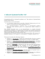
1.About SystemCrafter SC
SystemCrafter SC is a SystemC synthesis tool. This edition of SystemCrafter
targets Xilinx FPGAs.
SystemCrafter can be used either
●
in a hardware design flow, to provide a SystemC design entry tool to be
used as a front-end to the Xilinx synthesis tools; or
●
in a hardware/software co-design flow, to automatically produce
hardware from selected parts of a system-level model written in
SystemC.
This manual describes how to use SystemCrafter to compile SystemC
descriptions to hardware. It assumes that the reader has already obtained and
used the SystemC simulator, and is familiar with the SystemC documentation.
These can be obtained from www.systemc.org.
SystemCrafter SC version 3.0.0 has been tested using Xilinx ISE version 9.2i,
SystemC version 2.1.v1, Visual C++ .net version 7.1, and gcc version 3.2.3.
The manual includes the following chapters:
5
●
Chapter 2, "Introduction", shows how SystemCrafter fits into a typical
design flow from a SystemC description of a circuit to a Xilinx FPGA.
●
Chapter 3, “Using SystemCrafter SC In Your Design Flow”, describes
the design process in greater detail and illustrates this using the simple
GCD example provided with your SystemCrafter SC installation.
●
Chapter 4, "Invocation", explains how you can work with SystemCrafter
SC; using the graphical user interface, or via the command line.
Alternatively, you can use your existing C++ compiler's GUI and a
detailed description of this is in the section “Using Your Existing C++
Compiler's GUI”.
●
Chapter 5, “Language Reference”, lists the subset of SystemC that is
supported by the Starter Edition of SystemCrafter.
●
Chapter 6, “Synthesis and Simulation Guide”, discusses the different
outputs of SystemCrafter SC; SystemC, VHDL and Verilog.
User Manual 3.0.0
1.About SystemCrafter SC
●
6
Chapter 7, “Appendices”, provides general recommendations for use,
particularly when writing the input SystemC description.
www.systemcrafter.com
User Manual 3.0.0
2.Introduction
This chapter explains how SystemCrafter SC fits into a typical design process
starting with a SystemC description of a circuit and finishing with a
programmed FPGA. It includes the following sections:
●
Design Flow
●
Writing System C for Synthesis
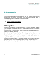
2.1 Design Flow
SystemCrafter compiles a SystemC description to RTL HDL (Register Transfer
Level Hardware Description Language) - either VHDL or Verilog - for further
synthesis by downstream tools.
The user writes a SystemC model, which is used with a test bench and a C++
compiler to simulate the design.
When the user is happy with their SystemC specification they can run
SystemCrafter. SystemCrafter SC will output a VHDL or Verilog description of
the circuit. This can be used with an appropriate test bench for simulation
and further synthesized using standard synthesis tools. For Xilinx FPGAs this
may be Xilinx XST and place and route tools.
SystemCrafter also produces a gate-level SystemC description of the output
HDL which can be used for verification in the original SystemC test bench.
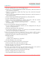
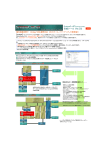
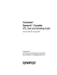
The design flow for a simple SystemC to hardware flow is shown below.
7
User Manual 3.0.0
2.Introduction
SystemC Model
Test Bench
SystemCrafter
Gate-level
SystemC Model
C++ Compiler
RTL HDL
HDL Test Bench
Simulation
Xilinx Tools
HDL Simulator
Xilinx FPGA
HDL Simulation
2.2 Writing System C for Synthesis
It will be necessary to refine an initial simulatable SystemC description to be
able to synthesize it to hardware. No synthesis tool will be able to compile any
SystemC program to efficient hardware.
This is because the complete
SystemC language is a superset of C++ designed for simulation, and it is not
possible to compile all constructs to hardware.
The above is true of VHDL and Verilog, which were also originally written as
simulation languages. VHDL and Verilog written for simulation purposes have
to be refined to use a synthesizable subset, for effective synthesis; SystemC is
the same.
To refine simulatable SystemC for synthesis using SystemCrafter SC, it is
necessary to use the SystemC constructs that SystemCrafter SC supports.
8
www.systemcrafter.com
User Manual 3.0.0
2.Introduction
These are described in the chapter, “Language Reference”.
9
www.systemcrafter.com
User Manual 3.0.0
3.Using SystemCrafter SC In Your Design
Flow
This chapter explains how you can fit SystemCrafter SC into a design flow.
First, the design flow is discussed in greater detail followed by a description of
how this can be managed using the SystemCrafter SC graphical user interface
(GUI). Finally, a very simple design example is introduced. The chapter
includes the following sections:
●
Detailed Design Flow
●
Using The SystemCrafter SC GUI
●
Example: Simple GCD Calculator
3.1 Detailed Design Flow
There are two flows that are used to synthesize and verify a SystemC design:
the first “system-level” flow directly simulates the SystemC files you have
written; the second “gate-level” flow runs SystemCrafter SC and then
simulates the synthesized circuit.
In the following description we will assume that your SystemC description has
been written in files circuit.h and circuit.cpp. The test bench is in files tester.h
and tester.cpp and both design and test bench are combined in main.cpp.
10
User Manual 3.0.0
3.Using SystemCrafter SC In Your Design Flow
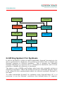
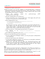
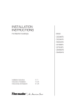
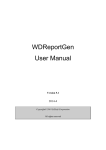
System-Level Flow
The system-level flow is quite straightforward. Circuit.cpp, main.cpp and
tester.cpp are compiled using your C++ compiler, and then linked together
with your SystemC library to produce an executable simulation. This is just
the standard SystemC simulation route.
tester.h
circuit.h
tester.cpp
main.cpp
systemc.lib
C++ Compiler
circuit.cpp
SystemLevel\
run.exe
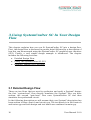
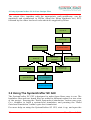
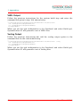
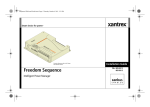
Gate-Level Flow
SystemC output
The gate-level flow introduces the use of SystemCrafter SC. First
SystemCrafter SC is used to synthesize circuit.cpp (and its include file
circuit.h). This produces a SystemC description of the synthesized circuit,
which is put in the subdirectory “GateLevel”, resulting in the files
GateLevel\circuit.cpp and GateLevel\circuit.h.
The gate-level circuit can be simulated for verification. GateLevel\circuit.cpp,
main.cpp and tester.cpp are compiled and linked with the SystemC library to
produce an executable simulation. Note that main.cpp now includes the
synthesized header file, GateLevel\circuit.h, and that GateLevel\circuit.h
includes a SystemC library of gate descriptions, craft_gatelibrary.h, which is
contained in the include directory of your distribution.
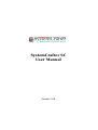
VHDL and Verilog output
Running SystemCrafter SC also produces a set of HDL files – either VHDL or
Verilog - that can be used with your standard synthesis tools. Additional files,
craft_gatelibrary.vhd (VHDL) and craft_gatelibrary.v (Verilog), are supplied as
part of the SystemCrafter distribution.
11
www.systemcrafter.com
User Manual 3.0.0
3.Using SystemCrafter SC In Your Design Flow
The output files, together with the appropriate craft_gatelibrary, can be
simulated and synthesized to FPGAs using the Xilinx synthesis tool, XST,
followed by the other low-level tools which are supplied by Xilinx.
circuit.h
circuit.cpp
craftgatelibrary.h
SystemCrafter
GateLevel\
circuit.h
tester.h
tester.cpp
main.cpp
systemc.lib
C++ Compiler
HDL output files
GateLevel\
circuit.cpp
GateLevel\run.exe
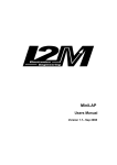
3.2 Using The SystemCrafter SC GUI
The SystemCrafter SC GUI is designed to make these flows easy to run. The
hardware files and test bench files are added to different nodes in a tree view
of the project. Pressing the “Build System-level simulation” button uses your
C++ compiler to build a system-level simulation, and pressing the “Build
Gate-level simulation” builds a gate-level simulation.
For more help on using the SystemCrafter SC GUI, start it up, and open the
12
www.systemcrafter.com
User Manual 3.0.0
3.Using SystemCrafter SC In Your Design Flow
help index by pressing F1, or clicking on the Help menu, and selecting Help
Topics.
Alternatively, you can use SystemCrafter SC within your existing C++
compiler's GUI. See the Appendix, section “Using Your Existing C++
Compiler's GUI” for this, which includes a detailed description of how to set
up the GCD project using SystemCrafter with Visual C++ .net 2003.
VHDL Output From The SystemCrafter SC GUI
This is the default output from SystemCrafter SC . Load your SystemC source
and header files into the tree view of your project. Set up the Build options for
your C++ compiler and the SystemC library and header then select Build HDL
and SystemCrafter SC will generate an RTL VHDL description of your design.
Verilog Output From The SystemCrafter SC GUI
SystemCrafter SC can output an RTL Verilog description of your design. Load
the source and header files into the tree view of your project. Set up the Build
options for your C++ compiler and the SystemC library and header. In the
Build options select the SystemCrafter options folder and enter
/vlog
as a command line option. Now select Build HDL and a Verilog description of
the input design will be generated.
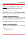
3.3 Example: Simple GCD Calculator
This example calculates the greatest common divisor (GCD) of two 32-bit
unsigned numbers.
SystemC
class circuit : public sc_module {
public:
sc_in<sc_uint<32> > in1, in2;
sc_out<sc_uint<32> > result;
sc_in<bool> start, clock;
sc_out<bool> finish;
void do_gcd ();
SC_CTOR (circuit) {
13
www.systemcrafter.com
User Manual 3.0.0
3.Using SystemCrafter SC In Your Design Flow
SC_THREAD(do_gcd);
sensitive_pos << clock;
}
};
void circuit::do_gcd()
{
sc_uint<32> xreg, yreg;
while (1) {
do {
wait();
} while (!start);
xreg = in1;
yreg = in2;
wait ();
while (xreg != yreg) {
if (xreg > yreg) {
xreg -= yreg;
} else {
yreg -= xreg;
}
wait ();
}
result = xreg;
finish = 1;
wait ();
finish = 0;
wait ();
}
}
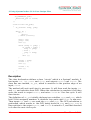
Description
The class declaration defines a class “circuit” which is a SystemC module. It
has inputs in1, in2, start and clock, and outputs result and finish. The
class has one method, do_gcd, which is sensitive to the positive edge of an
input, clock.
The method will wait until start is non-zero. It will then read the inputs in1
and in2, and calculate their GCD. When the calculation is complete it will then
write the result to output result, and raise finish to 1 for one cycle. It will
then iterate.
The definition of do_gcd initially declares two variables, xreg and yreg, which
hold 32-bit unsigned numbers. A do/while loop waits until start is non-zero.
Then inputs in1 and in2 are read into xreg and yreg. The GCD calculation is
performed, which results in the GCD being stored in xreg and yreg. xreg is
then written to the output result, and finish is raised to 1, and then lowered
to 0 after the next clock cycle.
14
www.systemcrafter.com
User Manual 3.0.0
3.Using SystemCrafter SC In Your Design Flow
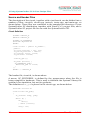
Source and Header Files
The description of the circuit, together with a test bench, can be divided into a
number of files: circuit.h, circuit.cpp, tester.h, tester.cpp, and main.cpp, as
shown below. These files are contained in the samples\gcd directory of your
SystemCrafter SC distribution, together with Visual C++ project files, and a
SystemCrafter SC project file for use with the SystemCrafter GUI.
Circuit Definition
#ifndef CIRCUIT_H
#define CIRCUIT_H
#ifndef SC_SYNTHESIS
#include "systemc.h"
#endif
class circuit : public sc_module {
public:
sc_in<sc_uint<32> > in1, in2;
sc_out<sc_uint<32> > result;
sc_in<bool> start, clock;
sc_out<bool> finish;
void do_gcd ();
SC_CTOR (circuit) {
SC_THREAD(do_gcd);
sensitive_pos << clock;
}
};
#endif // CIRCUIT_H
The header file, circuit.h, is shown above.
A macro, SC_SYNTHESIS, is defined by the preprocessor when the file is
being compiled to hardware. This is used to #include the SystemC library file
systemc.h for simulation, but not for synthesis.
The definition of do_gcd is placed in file circuit.cpp, as shown below.
#include “circuit.h”
void circuit::do_gcd()
{
sc_uint<32> xreg, yreg;
while (1) {
do {
wait();
} while (!start);
xreg = in1;
15
www.systemcrafter.com
User Manual 3.0.0
3.Using SystemCrafter SC In Your Design Flow
yreg = in2;
wait ();
while (xreg != yreg) {
if (xreg > yreg) {
xreg -= yreg;
} else {
yreg -= xreg;
}
wait ();
}
result = xreg;
finish = 1;
wait ();
finish = 0;
wait ();
}
}
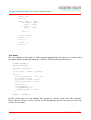
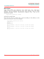
Test bench
We can define a test bench, with outputs supplying the inputs to circuit, and
an input which reads the output of circuit. This is placed in tester.h:
#ifndef TESTER_H
#define TESTER_H
#include <systemc.h>
class tester : public sc_module
{
public:
sc_out<sc_uint<32> > in1, in2;
sc_out<bool> start,
sc_in<bool> finish, clock;
sc_in<sc_uint<32> > result;
void do_it();
SC_CTOR(tester) {
SC_THREAD(do_it);
sensitive_pos << clock;
}
};
#endif // TESTER_H
In file tester.cpp we can supply the inputs to circuit, and read the outputs.
Note that we have to wait a cycle at the beginning of the test process for the
circuit to be reset.
16
www.systemcrafter.com
User Manual 3.0.0
3.Using SystemCrafter SC In Your Design Flow
#include "tester.h"
void tester::do_it()
{
start=0;
wait(); //wait for system reset
wait();
start=1;
in1 =75;
in2 =45;
wait();
start=0;
while (!finish.read()) {
wait();
}
cout << "result is " << result.read() << "\n";
wait();
}
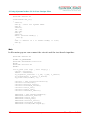
Main
In file main.cpp we can connect the circuit and the test bench together.
#include "tester.h"
#ifdef SC_GATELEVEL
#include “GateLevel\circuit.h”
#else
#include "circuit.h"
#endif
int sc_main (int argc , char *argv[]) {
circuit *circuit1;
tester * thetester;
sc_signal<sc_uint<32> > s_in1, s_in2, s_result;
sc_signal<bool> s_start, s_finish;
sc_clock clk1("clk1", 1);
circuit1 = new circuit("circuit1");
circuit1->clock(clk1);
circuit1->start(s_start);
circuit1->finish(s_finish);
circuit1->in1(s_in1);
circuit1->in2(s_in2);
circuit1->result(s_result);
thetester = new tester("tester");
thetester->result(s_result);
thetester->in1(s_in1);
thetester->in2(s_in2);
thetester->start(s_start);
thetester->finish(s_finish);
thetester->clock(clk1.signal());
17
www.systemcrafter.com
User Manual 3.0.0
3.Using SystemCrafter SC In Your Design Flow
sc_start(50);
return 0;
}
If the macro SC_GATELEVEL is defined then the synthesized header file, the
output of SystemCrafter SC, is included (the file GateLevel\circuit.h);
otherwise the input circuit header (circuit.h) is included. This is explained in
the section “Detailed Design Flow”.
18
www.systemcrafter.com
User Manual 3.0.0
4.Invocation
This chapter explains how to use SystemCrafter SC and what options are
available. It contains the following sections:
●
The SystemCrafter SC GUI
●
Command Line
●
Output Files
4.1 The SystemCrafter SC GUI
The SystemCrafter GUI is easy to use and helps you to manage your design
flow. A tree view allows design files and test bench files to be added to
separate nodes within the project. Both system-level and gate-level
simulations can be built.
For more help on using the SystemCrafter SC GUI, start it up, and open the
help index by pressing F1, or clicking on the Help menu, and selecting Help
Topics.
Alternatively, SystemCrafter may be be called from within your preferred
C++ compiler, so that you can continue to use your compiler's GUI. See
Appendices section “Using Your Existing C++ Compiler's GUI”.
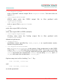
4.2 Command Line
The SystemCrafter SystemC synthesizer can be called from the command line
using the following command:
craft [options] inputfilename
Options are:
•
/oh outputhfilename
write a SystemC header output file to outputhfilename. You must also set
option /oc.
19
User Manual 3.0.0
4.Invocation
•
/oc outputcfilename
write a SystemC source output file to outputcfilename. You must also set
option /oh.
•
/ovh outputvhdlfilename
(VHDL only) write the
outputvhdlfilename.
•
VHDL
output
file
to
files
prefixed
with
/rpt reportfilename
write a report file to reportfilename.
•
/vlog
write the output HDL in Verilog.
•
/vhdl
write the output HDL in VHDL (default).
•
/ove outputvlogfilename
(Verilog only) write
outputvlogfilename.
the
Verilog
output file
to files prefixed with
Advanced options are
•
/doasyncreset
synthesize resets specified by reset_signal_is as asynchronous resets,
instead of synchronous.
•
/oa outputarchitecturename
use outputarchitecturename as the name of the architecture in the VHDL
output. Eg /oa RTL will name the architecture “RTL”. If you use a %s in the
outputarchitecturename it will be replaced with the name of the entity. Eg
/oa %s will name the architecture circuit for an entity circuit, and /oa
%s_RTL will name the architecture circuit_RTL.
Options may start with a leading '/' or '-'. E.g.
craft -ovh vhdl_ circuit.cpp
and
craft /ovh vhdl_ circuit.cpp
are both permitted.
20
www.systemcrafter.com
User Manual 3.0.0
4.Invocation
4.3 Output Files
VHDL Output
VHDL is the default output from SystemCrafter SC. It can be generated from
the SystemCrafter GUI by selecting Build VHDL after having loaded a project
and setting up the build options. Alternatively, it can be generated from the
command line using the following command:
craft [/vhdl] [options] inputfilename
See the previous section “Command Line” for available options.
Verilog Output
Verilog can be generated from SystemCrafter SC from the GUI. Load your
SystemC project files and set up the Build options for your C++ compiler and
the SystemC library and header file. Select the SystemCrafter Options folder
and enter
/vlog
in the command line field. Now if you select Build HDL, SystemCrafter SC will
generate a Verilog description of your design.
Alternatively, you can use the command line to obtain an RTL Verilog
description of your SystemC input design using the following command:
craft /vlog [options] inputfilename
See the previous section “Command Line” for detailed options.
Default Filenames
The default output filenames are based on the “basefilename”, which is the
input filename less the final extension, i.e. the basefilename of circuit.cpp is
circuit, and the basefilename of circuit.one.cpp is circuit.one.
The default action of SystemCrafter is to write VHDL or Verilog descriptions
to files whose names are based on the class, function and method names in
the SystemC input, prefixed with basefilename and an underscore, and
suffixed with .vhd. The default name of the architecture is the basefilename
suffixed with “_syn”. By default, no report file or gate-level SystemC files are
written.
VHDL Example
With no options, functions myname1() and myname2() in file myfile.cpp
compile to VHDL files myfile_myname1.vhd and myfile_myname2.vhd, and no
21
www.systemcrafter.com
User Manual 3.0.0
4.Invocation
report file or SystemC files are written. The entities will be named myname1
and myname2, and the architectures myname1_syn and myname2_syn.
Verilog Example
With no options, functions myname1() and myname2() in file myfile.cpp
compile to Verilog files myfile_myname1.v and myfile_myname2.v, and no
report file or SystemC files are written.
The modules will be named
myname1 and myname2.
Output to a Subdirectory
You can use the directory hierarchy separator in a filename to output files to a
different directory. For Windows this is a \, so you can output all of your VHDL
files to a subdirectory called vhdl using the following command:
craft /ovh vhdl\ circuit.cpp
The subdirectory must already exist.
22
www.systemcrafter.com
User Manual 3.0.0
5.Language Reference
This chapter describes the subset of SystemC supported by the Starter Edition
of SystemCrafter. It contains the following sections:
23
●
Datatypes
●
Expressions
●
Statements
●
Classes, Structs and Functions
●
Interconnected Classes
●
Separate Compilation and Black Boxes
●
Rams
User Manual 3.0.0
5.Language Reference
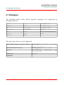
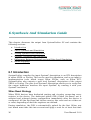
5.1 Datatypes
The following table shows which SystemC datatypes are supported by
SystemCrafter SC.
sc_int
sc_lv
unsigned int
sc_uint
sc_bv
unsigned long
int
sc_bigint
unsigned char
unsigned
sc_biguint
const
bool
short
Single dimensional arrays
sc_bit
long
enum
sc_logic
char
The data types below are not supported.
user-defined classes, structs, unions
fixed point (sc_fixed,
sc_fix, sc_ufix )
multi-dimensional arrays
floating point (float, double)
pointers
functional-style
sc_uint<3>(5))
references
typedef
sc_ufixed,
constructors
(e.g.
templates
24
www.systemcrafter.com
User Manual 3.0.0
5.Language Reference
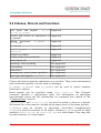
5.2 Expressions
Unary expressions: + - ! ~
Supported
Binary expressions: * / % + - << >> < > Supported
<= >= & ^ | && || == !=
Assignment expressions: = *= /= %= += -= Supported
<<= >>= &= ^= |=
Conditional expression: x?y:z
Supported
Postincrement, postdecrement, preincrement Supported
and predecrement
Supported
.or_reduce().xor_reduce()
.and_reduce() .range(x,1)
(x,y) (concatenation)
a[x] where a is an array (single dimensional Supported
array access)
a[x] where a is variable of an appropriate Supported
datatype (bit selection)
x.read(), x.write(), where x is a port
Supported
multidimensional arrays
Not supported
part select (range())
Not supported
Casting is not supported, but datatypes are automatically converted when
required. For instance:
sc_uint<4> a;
sc_int<3> b;
sc_uint<9> c;
sc_uint<7> d;
d = a + b*c;
is permitted, and it is not necessary to cast the results, as in some other tools.
25
www.systemcrafter.com
User Manual 3.0.0
5.Language Reference
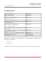
5.3 Statements
Labeled statements: case, default
Supported
Selection statements: if, if else, Supported
switch
Iteration
statements
do/while, for
:
while, Supported
The last statement in a loop must be a
wait() statement.
Jump
statements:
break
(only Supported
supported in a switch statement),
return
wait()
Supported
Used to specify a clock transition
wait_until()
Not supported
Jump statements: continue, break Not supported
(other than in a switch statement)
26
www.systemcrafter.com
User Manual 3.0.0
5.Language Reference
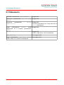
5.4 Classes, Structs and Functions
port types and signals:
sc_out, sc_signal
sc_in, Supported
classes and structs as subclasses of Supported
sc_module
thread
processes:
SC_CTHREAD
SC_THREAD
Supported
SC_METHOD
sensitive_pos,
sensitive
, Supported
sensitive_neg, Supported
instance variables
Supported
member functions (methods)
Supported
reset_signal_is()
Supported
watching, local watching
Not supported
overloading
Not supported
inheritance
Not supported
namespaces, nested name specifiers
Not supported
port types and signals: sc_inout
Not supported
Classes and structs must be subclasses of sc_module. They can be instantiated
and connected together, but not used as datatypes.
SC_THREAD, SC_METHOD, and SC_CTHREAD can be used to attach member
functions to classes.
Reset signals can be specified using reset_signal_is. This SystemC
construct specifies a synchronous reset. For information on specifying
asynchronous resets see the information on command line options in the
“Command Line” section.
sensitive_pos and sensitive_neg are used to attach a clock to a thread.
All threads in a class must be clocked by the same clock, of the same polarity.
SC_METHODs may be clocked or unclocked. Unclocked (combinatorial)
SC_METHODs must be sensitive to all inputs. Clocked SC_METHODs will be edge
sensitive (sensitive_pos or sensitive_neg) to a clock signal. They may also
be edge sensitive to a reset signal.
27
www.systemcrafter.com
User Manual 3.0.0
5.Language Reference
5.5 Interconnected Classes
SystemCrafter will synthesize classes that have been instantiated. These
classes can be connected together using signals (sc_signal). No other
SystemC channels are supported.
In the following example three instances of “circuit1” and one instance of
“circuit2” are instantiated and connected together in “circuit”.
class circuit1 : public sc_module
{
public:
sc_in<sc_uint<3> > in1;
sc_out<sc_uint<3> > out1;
sc_in<bool> clk1;
void do_it();
SC_CTOR (circuit1) {
SC_THREAD(do_it);
sensitive_pos << clk1;
}
};
class circuit2 : public sc_module
{
public:
sc_in<sc_uint<3> > in2;
sc_out<sc_uint<3> > out2;
sc_in<bool> clk2;
void do_it();
SC_CTOR (circuit2) {
SC_THREAD(do_it);
sensitive_pos << clk2;
}
};
class circuit : public sc_module
{
public:
sc_in<sc_uint<3> > a;
sc_out<sc_uint<3> > g, out2, out3;
sc_in<bool> clk;
sc_signal<sc_uint<3> > s1;
sc_signal<sc_uint<3> > s2;
void do_it();
SC_CTOR (circuit) {
SC_THREAD(do_it);
sensitive_pos << clk;
28
www.systemcrafter.com
User Manual 3.0.0
5.Language Reference
// beginning of contents
circuit1 *c1 = new circuit1("circuit1");
circuit2 *c2 = new circuit2("circuit2");
circuit1 *c3 = new circuit1("circuit3");
circuit1 *c4 = new circuit1("circuit4");
// end of contents
// beginning of connections
c1->in1(a);
c1->out1(s1);
c1->clk1(clk);
c2->in2(s1);
c2->out2(s2);
c2->clk2(clk);
c3->in1(s2);
c3->out1(g);
c3->clk1(clk);
c4->in1(a);
c4->out1(out2);
c4->clk1(clk);
// end of connections
}
};
29
www.systemcrafter.com
User Manual 3.0.0
5.Language Reference
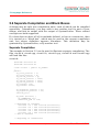
5.6 Separate Compilation and Black Boxes
A design may be split into compilation units, each of which can be compiled
separately. Alternatively, you may wish to use another tool for part of your
design, and link its output with the output of SystemCrafter. These related
concepts are both supported.
If a class does not have all of its methods defined, or has no constructor, then
it is treated as a “black box”, which may be used in the current compilation
unit, but whose definition appears elsewhere. This definition may be
generated by SystemCrafter, or by another tool.
Separate Compilation
The example in Section 5.5 can be used to illustrate separate compilation. The
files circuit.h, circuit.cpp, circuit1.h, circuit1.cpp, circuit2.h and circuit2.cpp
will look like this:
circuit.h:
#include "circuit1.h"
#include "circuit2.h"
class circuit : public sc_module
{
public:
sc_in<sc_uint<3> > a;
sc_in<sc_uint<3> > b;
sc_out<sc_uint<3> > g;
sc_out<sc_uint<3> > out2;
sc_out<sc_uint<3> > out3;
sc_out<sc_uint<3> > out4;
sc_in<bool> clk;
sc_in<bool> start;
sc_signal<sc_uint<3> > s1;
sc_signal<sc_uint<3> > s2;
void do_it();
SC_CTOR (circuit) {
SC_THREAD(do_it);
sensitive_pos << clk;
// beginning of contents
circuit1 *c1 = new circuit1("circuit1");
circuit2 *c2 = new circuit2("circuit2");
circuit1 *c3 = new circuit1("circuit3");
circuit1 *c4 = new circuit1("circuit4");
circuit1 *c5 = new circuit1("circuit5");
// end of contents
// beginning of connections
30
www.systemcrafter.com
User Manual 3.0.0
5.Language Reference
c1->in1(a);
c1->out1(s1);
c1->clk1(clk);
c1->start(start);
c2->in2(s1);
c2->out2(s2);
c2->clk2(clk);
c2->start(start);
c3->in1(s2);
c3->out1(g);
c3->clk1(clk);
c3->start(start);
c4->in1(a);
c4->out1(out2);
c4->clk1(clk);
c4->start(start);
c5->in1(b);
c5->out1(out4);
c5->clk1(clk);
c5->start(start);
// end of connections
}
};
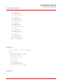
circuit1.h:
class circuit1 : public sc_module
{
public:
sc_in<sc_uint<3> > in1;
sc_out<sc_uint<3> > out1;
sc_in<bool> clk1;
sc_in<bool> start;
int instance;
void do_it();
SC_CTOR (circuit1) {
SC_THREAD(do_it);
sensitive_pos << clk1;
}
};
circuit2.h:
31
www.systemcrafter.com
User Manual 3.0.0
5.Language Reference
class circuit2 : public sc_module
{
public:
sc_in<sc_uint<3> > in2;
sc_out<sc_uint<3> > out2;
sc_in<bool> clk2;
sc_in<bool> start;
void do_it();
SC_CTOR (circuit2) {
SC_THREAD(do_it);
sensitive_pos << clk2;
}
};
circuit.cpp:
#include "circuit.h"
void circuit::do_it()
{
while (!start) wait();
while (1) {
out3 = a.read() + 5;
wait();
}
}
circuit1.cpp:
#include "circuit1.h"
void circuit1::do_it()
{
while (!start) wait();
while (1) {
out1 = instance;
instance = in1.read();
wait();
}
}
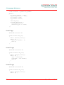
circuit2.cpp:
#include "circuit2.h"
void circuit2::do_it()
{
while (!start) wait();
while (1) {
32
www.systemcrafter.com
User Manual 3.0.0
5.Language Reference
out2 = in2.read() + 2;
wait();
}
}
circuit.cpp
can
be
compiled
using
SystemCrafter
to
produce
GateLevel\circuit.h and GateLevel\circuit.cpp, even though the methods
circuit1::do_it() and circuit2::do_it() are not defined.
Circuit1 and circuit2 will be treated as black boxes, as their methods have not
been defined, and the gate-level simulation output file will #include
GateLevel\circuit1.h and GateLevel\circuit2.h. These files will be produced
when circuit1.cpp and circuit2.cpp are compiled.
Similarly, the VHDL output of SystemCrafter will produce component
declarations for circuit1 and circuit2 which enable them to be instantiated.
The entity and architecture definitions will be produced by SystemCrafter
when circuit1.cpp and circuit2.cpp are compiled.
Black Boxes
Instead of using SystemCrafter to produce VHDL and SystemC definitions of
circuit1 and circuit2, they may be produced using another synthesis tool, or
written by hand.
All that is necessary to be able to carry out a gate-level simulation is to
provide header files GateLevel\circuit1.h and GateLevel\circuit2.h. Similarly,
to be able to simulate and synthesize the VHDL output you must provide
architecture and entity definitions for circuit1 and circuit2.
33
www.systemcrafter.com
User Manual 3.0.0
5.Language Reference
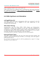
5.7 Rams
Rams are efficient hardware blocks which behave somewhat like arrays. The
major difference is that they are enormously more efficient to implement in
hardware, but can only access one address (index) in each clock cycle.
SystemCrafter provides both simulation and synthesis support for rams.
craft_systemlibrary.h contains definitions for modules to aid simulation.
To use these
you must declare your class as a subclass of
sc_module_ram_craft, #include “craft_systemlibrary.h” for system-level
simulation, and only use your ram in a method of that class, not a function.
As an example, the following description declares a ram “aram” of length 512,
which stores data of type sc_uint<32>. The thread writes 7 to a[5], and then
reads from a[5] into the output.
#ifndef SC_SYNTHESIS
#include “systemc.h”
#include “craft_systemlibrary.h”
#endif
class circuit : public sc_module_ram_craft
{
public:
sc_in<sc_uint<32> > in;
sc_out<sc_uint<32> > out;
sc_in<bool> clock;
void do_it ();
SC_CTOR (circuit)
{
SC_THREAD(do_it);
sensitive_pos << clock;
}
};
void circuit::do_it()
{
ram<sc_uint<32>,512> aram(this);
aram.write(5,7);
wait();
out = aram.read(5);
wait();
}
The simulation methods supplied in craft_systemlibrary.h will give an error
during simulation if you attempt to use two different addresses in one clock
cycle. SystemCrafter does not give any errors or warnings.
Multi-port rams are not supported in this version of SystemCrafter.
34
www.systemcrafter.com
User Manual 3.0.0
5.Language Reference
Block Rams
Some Xilinx FPGAs also implement rams called block rams, which have
different timing conditions and are even more efficient. See the Xilinx
literature for more details. SystemCrafter supports these. They can be
declared as follows:
ram_block<sc_uint<32>,8> a(this);
and used as normal ram.
Note that the data of a block ram is read according to the address on the
previous clock cycle. Here is an example:
ram_block<sc_uint<32>,512>
b.write(5,7);
wait();
b.write(8,9);
wait();
out = b.read(5); //will be
wait();
out = b.read(8); //will be
wait();
out = b.read(3); //will be
wait();
35
b(this);
9 (ie b[8] (8 from last cycle))
7 (ie b[5] (5 from last cycle))
9 (ie b[8] (8 from last cycle))
www.systemcrafter.com
User Manual 3.0.0
6.Synthesis And Simulation Guide
This chapter discusses the output from SystemCrafter SC and contains the
following sections:
●
Introduction
●
VHDL Synthesis and Simulation
●
Verilog Synthesis and Simulation
●
SystemC Synthesis and Simulation
●
Differences Between System-Level and Gate-Level Simulation
●
Name Mappings
6.1 Introduction
SystemCrafter compiles the input SystemC description to an RTL description
in either VHDL or Verilog. This can be used for simulation, and as an input to
implementation tools which target Xilinx FPGAs, such as Xilinx XST.
SystemCrafter also outputs a gate level SystemC description of the output
VHDL or Verilog. The gate level SystemC description allows you to verify that
the output behaviour matches the input SystemC by running it with your
SystemC test bench.
Xilinx Reset Strategy
Xilinx FPGA devices have dedicated routing and circuitry connecting every
register in the device. The dedicated global GSR (Global Set-Reset) net is
asserted and released during configuration immediately after the device is
configured. All the flip-flops and latches receive this reset and are either set
or reset, depending on how the registers are defined.
During simulation, the GSR is automatically pulsed for the first 100ns: any
test bench must take this into account and apply a wait for at least that time
36
User Manual 3.0.0
6.Synthesis And Simulation Guide
before applying stimuli to the circuit under test.
VHDL and Verilog have different ways of modeling the GSR signal and these
are explained in sections “VHDL Synthesis and Simulation” and “Verilog
Synthesis and Simulation” below.
6.2 VHDL Synthesis and Simulation
craft_gatelibrary.vhd
The VHDL output uses some subprograms which are contained in the file
craft_gatelibrary.vhd. This is supplied in the vhdl subdirectory of the
SystemCrafter distribution.
Xilinx Reset Strategy
SystemCrafter uses the Xilinx VHDL “ROC” (Reset on Configuration)
component to emulate the behaviour of the GSR. The ROC component is
connected to a reset signal, which is used to reset certain registers. This will
be optimised away by the Xilinx synthesizer. Some registers do not require
resetting, and these are not connected to the reset signal.
For further details on the ROC component see the Xilinx manuals.
Input and Output Types
The VHDL output will preserve the size of the input and output signals, and
produce a type std_logic (for types of width 1), or std_logic_vector (for types of
width greater than 1).
E.g. an input “a”of type sc_uint<3> will be synthesized to a input “a” of type
std_logic_vector(2 downto 0).
37
www.systemcrafter.com
User Manual 3.0.0
6.Synthesis And Simulation Guide
6.3 Verilog Synthesis and Simulation
craft_gatelibrary.v
The Verilog output uses some subprograms which are contained in the file
craft_gatelibrary.v. This is supplied in the vlog subdirectory of the
SystemCrafter distribution.
Xilinx Reset Strategy
SystemCrafter uses the module ROC_craft defined in the craft_gatelibrary.v to
emulate the behaviour of the GSR pulse. The module has an output signal
called GSR which is connected to a reset signal and is used to reset certain
registers. This will be optimised away by the Xilinx synthesizer. Some
registers do not require resetting, and these are not connected to the reset
signal.
For further details see the Xilinx manuals.
Input and Output Types
The Verilog output will preserve the size of the input and output signals
declaring them as input or output ports to the top level module.
6.4 SystemC Synthesis and Simulation
SystemCrafter writes a gate-level SystemC netlist, which describes the same
circuit as the VHDL or Verilog output. This can be used in your original
SystemC test bench for verifying the output of SystemCrafter.
craft_gatelibrary.h
The gate-level SystemC output from SystemCrafter #includes a gate-level
library, craft_gatelibrary.h, which is supplied with your distribution. This
library describes standard components such as inverters and registers. You
will need to ensure that you add the path to this include file to the options
uses in your C++ compiler.
38
www.systemcrafter.com
User Manual 3.0.0
6.Synthesis And Simulation Guide
Input and Output Types
SystemCrafter preserves the types of the inputs and outputs of your circuit in
the gate-level SystemC description. So an input “a” of type sc_uint<3> will be
synthesized to a gate-level SystemC description with an input “a” of type
sc_uint<3>.
6.5 Differences Between System-Level and Gate-Level
Simulation
The simulation of the SystemC input and output of SystemCrafter should
produce the same results. However, due to the properties of the SystemC
simulator and gate-level circuits, there are some cases where a badlydesigned circuit or test bench could produce different results. These are
detailed below:
Reset Strategy
Some registers must be reset to a known state at the beginning of the gatelevel simulation. This is accomplished by setting the outputs of these registers
to 0 until sc_simulation_time() is no longer less than 1.
This means that the simulation of the circuit won't start until after time step 1.
Timing of sensitive_neg
Threads that are sensitive to the negative edge of the clock (sensitive_neg) are
implemented using an inverter in the clock line of a register. This means that
there may be minor timing differences between the start of the system-level
simulation of the thread, and the start of the gate-level simulation of the
thread. In particular these will occur if you arrange for inputs to change
exactly on the clock edge, which is bad practice.
Uninitialized Variables
Variables that are used before they have been written have an undefined
value in C++, but most compilers set them to 0. A simulation of the VHDL or
Verilog description generated by SystemCrafter will use an undefined value.
39
www.systemcrafter.com
User Manual 3.0.0
6.Synthesis And Simulation Guide
6.6 Name Mappings
SystemCrafter preserves the names you have used in your system-level
description.
If you synthesize a class “circuit”, with inputs “a” and “b” and output “c”, then
the gate-level SystemC output contains a class with the same names.
Similarly, the VHDL output will contain an entity “circuit” and the Verilog
output a module with the same inputs and outputs.
Names which are VHDL or Verilog keywords cannot be preserved in this way,
as this would result in an incorrect HDL description. Such names are given
the suffix _vhdl_craft and _vlog_craft.
VHDL Example
An input “in” will be compiled to a VHDL
“in_vhdl_craft”, because “in” is a VHDL keyword.
description
with
input
Verilog Example
An input “input” will be compiled to a Verilog description with input
“input_vlog_craft” because “input” is a Verilog keyword.
Internally Generated Names
Internally generated names have the suffix “_craft”.
40
www.systemcrafter.com
User Manual 3.0.0
7. Appendices
7.1 Hints and Tips
41
●
Don't expect any synthesizer to produce efficient hardware from a
SystemC program written for simulation. You can make your hardware
faster and smaller by thinking carefully and refining it.
●
It is much easy to start writing your SystemC project using the subset of
the language supported by SystemCrafter, than to use the full language
and then refine your design for synthesis.
●
Think about what happens in each clock cycle.
●
Decide where to process in parallel.
●
Minimize the width of variables. Don't use an int where an sc_uint<3> is
large enough.
●
Use unsigned widthed variables wherever possible (ie sc_uint<>).
●
Use rams instead of arrays where possible. Think about whether you can
use a block ram.
●
Don't take the size of the circuit written by SystemCrafter as a useful
metric – the synthesis process introduces redundant logic which will be
removed by downstream tools.
●
The gate-level SystemC simulation will require the SystemC simulator to
process much more data that the system-level simulation. Simulation
will be faster if you split your program across several input files, and
only simulate one at gate level at a time.
●
Some useful macros, such as SC_MODULE(), are defined in a header
file, craft_systemc.h, which is supplied in the include directory of the
distribution.
User Manual 3.0.0
7. Appendices
7.2 Using Your Existing C++ Compiler's GUI
You can use SystemCrafter SC within your existing C++ compiler's GUI. This
allows you to continue to use the GUI that you are familiar with, and once it
has been set up it is very straightforward to use. The C++ compiler calls
SystemCrafter from your compilation sequence, which will then both simulate
the gate-level SystemC output, and automatically generate HDL files for input
to downstream tools. You do this in a similar way to how you would call other
external compilation tools, such as lex or yacc.
Before reading this explanation, make sure that you are familiar with your
compiler's support for calling external tools such as lex and yacc. Visual C++
calls this a “custom build step”.
As an example we'll show how to setup the GCD project in the samples\gcd
directory of your SystemCrafter SC distribution using SystemCrafter SC with
Visual C++ .net 2003. The principles apply equally to other compilers. The
Visual C++ solution and project files are contained in your distribution.
Basic Principles
Set up two configurations: GateLevel and SystemLevel.
In the GateLevel configuration use a “custom-build step” to run SystemCrafter
SC on circuit.cpp, generating two files GateLevel\circuit.cpp, and
GateLevel\circuit.h.
Include these in the project, which allows them to be compiled and linked with
the SystemC library, producing the gate-level simulation.
The system-level simulation just uses the standard SystemC simulation on
your input files, and GateLevel\circuit.cpp and GateLevel\circuit.h are
excluded from the build.
Setup For Visual C++
1. Open a new Win32 console project called “gcd”. Click on Empty Project in
the application settings.
2. Add circuit.cpp, tester.cpp and main.cpp as source files.
3. Add circuit.h and tester.h as header files.
4. Open the Configuration Manager. For the gcd entry in the Project Contexts
table, add new configurations SystemLevel and GateLevel. Delete
configurations Debug and Release by selecting the Edit option in the drop
down. Close the Configuration Manager window.
5. Now open the gcd project properties pages
42
www.systemcrafter.com
User Manual 3.0.0
7. Appendices
a) Set the configuration to be “All Configurations”.
b) Under C/C++/General/Additional Include Directories, add the location of
your systemc.h include file.
c) Under C++/Language, enable Run Time Type Info, which the SystemC
libraries require.
d) Under Linker/General/Additional Library Directories, add the location of
your systemc.lib file.
e) Under Linker/Input/Additional Dependencies, add systemc.lib.
f) Set the configuration to be “GateLevel”.
g) Under C/C++/General/Additional include directories, add the include
directory from your SystemCrafter SC distribution.
h) Under
C/C++/Preprocessor/Preprocessor
SC_GATELEVEL.
definitions,
add
6. Now you can build the System-level simulation:
a) In the Configuration Manager window, set the configuration for the gcd
project to be SystemLevel.
b) From the build menu select Build gcd.
c) If the build completed correctly, you will have an executable simulation
gcd.exe in the SystemLevel subdirectory.
7. Now we'll setup the GateLevel simulation. First we need to add the names
of the synthesized files, the output from SystemCrafter SC, to the project.
a) Click on source files, and select add new item.
b) Set the location
i. Click browse
ii. Make a new subdirectory, GateLevel.
c) Set the filename to be circuit.cpp.
8. Now add the synthesized header file to the project.
a) Click on header files, and select add new item.
b) Set the location to be the new GateLevel subdirectory.
c) Set the filename to be circuit.h.
9. We don't want GateLevel\circuit.cpp and GateLevel\circuit.h to be used in
the SystemLevel build, so set the property pages accordingly:
a) Open the property pages for GateLevel\circuit.cpp
b) Set the configuration to be SystemLevel.
c) Set General/Excluded From Build, to Yes.
43
www.systemcrafter.com
User Manual 3.0.0
7. Appendices
d) Repeat for GateLevel\circuit.h.
10.Now we need to set up the compiler to call SystemCrafter to generate
GateLevel\circuit.cpp and GateLevel\circuit.h. This is done using a “Custom
Build Step”, which is a standard way of calling external tools, and is well
documented in the Visual C++ manual.
a) Open
the
property
gcd\GateLevel\circuit.cpp).
pages
for
gcd\circuit.cpp
(NOT
b) Set the configuration to be GateLevel.
c) Under General/Tool set “Custom Build Tool”. Click apply and you'll now
be able to see entries for custom build steps.
d) Set Command Line to be
“c:\Program Files\SystemCrafter\SystemCrafter SC\bin\craft”
/oh “$(TargetDir)$(InputName).h”
/oc “$(TargetDir)$(InputFileName)”
“$(InputPath)”
Put this all on one line, and be careful not to put spaces between the )
and $. NOTE: if you cut and paste from this manual you will have to type
in the speech marks '”' again otherwise the build will not work. This also
applies to the other custom build instructions below.
e) Set Description to “Performing SystemCrafter SC synthesis”.
f) Set
Outputs
$(InputFileName)"
to
be
"$(TargetDir)$(InputName).h";
"$(TargetDir)
g) Set Additional Dependency the to be "$(InputDir)$(InputName).h"
11.Now you can build the gate-level simulation:
a) In the Configuration Manager window, set the gcd project configuration
to be GateLevel.
b) From the build menu select Build gcd.
c) If the build completed correctly, you will have an executable simulation
gcd.exe in the GateLevel subdirectory.
d) Visual C++ will also tell you that the GateLevel\circuit.cpp and
GateLevel\circuit.h have been modified outside the source editor and ask
if you wish to reload. This is because SystemCrafter SC has output
synthesized SystemC to these files so click Yes to all.
Use
Now, when you set the gcd project configuration to be GateLevel, Visual C++
will call SystemCrafter and run the simulation on the generated gate-level
SystemC description, and also generate a set of VHDL files.
When you set the gcd project configuration to SystemLevel, Visual C++ will
run the simulation directly from the files that you have written.
44
www.systemcrafter.com
User Manual 3.0.0
7. Appendices
VHDL Output
Follow the previous instructions for the custom build step and enter the
command line given in step 10d, shown below.
“c:\Program Files\SystemCrafter\SystemCrafter SC\bin\craft”
/oh “$(TargetDir)$(InputName).h”
/oc “$(TargetDir)$(InputFileName)”
“$(InputPath)”
When you set the gcd configuration to be GateLevel and select Build gcd,
SystemCrafter SC will generate a set of VHDL files.
Verilog Output
Follow the previous instructions but add the verilog output option to the
command line for the custom build step:
“c:\Program Files\SystemCrafter\SystemCrafter SC\bin\craft” /vlog
/oh “$(TargetDir)$(InputName).h”
/oc “$(TargetDir)$(InputFileName)”
“$(InputPath)”
When you set the gcd configuration to be GateLevel and select Build gcd,
SystemCrafter SC will generate a set of Verilog files.
45
www.systemcrafter.com
User Manual 3.0.0