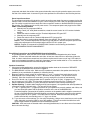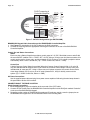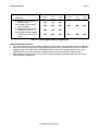
1
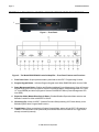
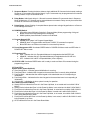
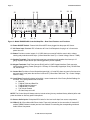
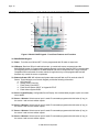
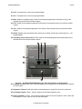
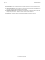
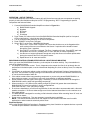
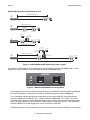
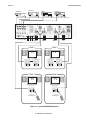
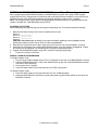
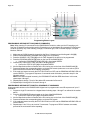
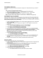
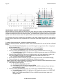
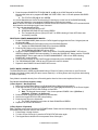
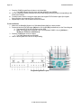
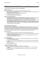
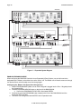
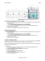
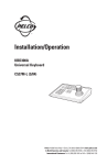
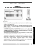
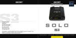
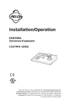
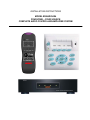
INSTALLATION INSTRUCTIONS MODEL BXAUDIO4X4 FOUR ZONE – FOUR SOURCE COMPLETE AUDIO CONTROLLER/AMPLIFIER SYSTEM Page: 2 Model BXAUDIO4X4 SAFETY INSTRUCTIONS - READ BEFORE OPERATING EQUIPMENT CAUTION: TO REDUCE THE RISK OF ELECTRIC SHOCK, DO NOT REMOVE COVER (OR BACK) NO USER-SERVICEABLE PARTS INSIDE REFER SERVICING TO QUALIFIED SERVICE PERSONNEL The lightning flash with arrowhead symbol, within an equilateral triangle, is intended to alert the user to the presence of un-insulated “dangerous voltage” within the product’s enclosure that may be of sufficient magnitude to constitute a risk of electric shock to persons. The exclamation point within an equilateral triangle is intended to alert the user to the presence of important operating and maintenance (servicing) instructions in the literature accompanying the appliance. WARNING TO REDUCE THE RISK OF FIRE OR ELECTRIC SHOCK, DO NOT EXPOSE THIS APPLIANCE TO RAIN OR MOISTURE. This product was designed and manufactured to meet strict quality and safety standards. There are, however, some installation and operation precautions, which you should be particularly aware of. 1. 2. 3. 4. 5. 6. 7. 8. 9. 10. 11. 12. 13. 14. 15. 16. 17. 18. Read Instructions – All the safety and operating instructions should be read before the appliance is operated. Retain Instructions – The safety and operating instructions should be retained for future reference. Heed Warnings – All warnings on the appliance and in the operating instructions should be adhered to. Follow Instructions – All operating and use instructions should be followed. Water and Moisture – The appliance should not be used near water – for example, near a bathtub, washbowl, kitchen sink, laundry tub, in a wet basement, or near a swimming pool, etc. Carts and Stands – The appliance should be used only with a cart or stand that is recommended by the manufacturer. An appliance and cart combination should be moved with care. Quick stops, excessive force, and uneven surfaces may cause the appliance and cart combination to overturn. Wall or Ceiling Mounting – The appliance should be mounted to a wall or ceiling only as recommended by the manufacturer. Ventilation – The appliance should be situated so that its location or position does not interfere with its proper ventilation. For example, the appliance should not be situated on a bed, sofa, rug, or similar surface that may block the ventilation openings; or, placed in a built-in installation, such as a bookcase or cabinet that may impede the flow of air through the ventilation openings. Heat – The appliance should be situated away from heat sources such as radiators, heat registers, stoves, or other appliances (including amplifiers) that produce heat. Power Sources – The appliance should be connected to a power supply only of the type described in the operating instructions or as marked on the appliance. Grounding or Polarization – Precautions should be taken so that the grounding or polarization means of an appliance is not defeated. Power-Cord Protection – Power- supply cords should be routed so that they are not likely to be walked on or pinched by items placed upon or against them, paying particular attention to cords at plugs, convenience receptacles, and the point where they exit from the appliance. Cleaning – The appliance should be cleaned only as recommended by the manufacturer. Power Lines – An outdoor antenna should be located away from the power lines. Nonuse Periods – The power cord of the appliance should be unplugged from the outlet when left unused for a long period of time. Object and Liquid Entry – Care should be taken so that objects do not fall and liquids are not spilled into the enclosure through openings. Damage Requiring Service – The appliance should be serviced by qualified service personnel when: A. The Power-supply cord or the plug has been damaged; or B. Objects have fallen, or liquid has spilled into the appliance; or C. The appliance has been exposed to rain; or D. The appliance does not appear to operate normally or exhibits a marked change in performance; or E. The appliance has been dropped, or the enclosure damaged. Servicing – The user should not attempt to service the appliance beyond that described in the operating instructions. All other servicing should be referred to qualified service personnel. © 2005 Xantech Corporation Model BXAUDIO4X4 Page: 3 TABLE OF CONTENTS Section Title Page SAFETY INSTRUCTIONS - READ BEFORE OPERATING EQUIPMENT ........................................................ 2 TABLE OF CONTENTS ................................................................................................................................... 3 SECTION 1.0: GENERAL INFORMATION....................................................................................................... 4 CONTROLLER/AMPLIFIER FEATURES..................................................................................................... 5 KEYPAD FEATURES .................................................................................................................................. 5 SECTION 2.0: BXAUDIO4X4 CONTROLLER/AMPLIFIER FEATURE DESCRIPTIONS.................................. 6 SECTION 3.0: BXAUDIO4X4 LC4KP KEYPAD FEATURE DESCRIPTIONS................................................. 10 SECTION 4.0: INSTALLATION...................................................................................................................... 13 OPERATION – OUT-OF-THE-BOX............................................................................................................ 13 BXAUDIO4X4 CONTROLLER/AMPLIFIER PHYSICAL LOCATION AND MOUNTING ............................. 13 LC4KP Keypad Installation Instructions ................................................................................................. 14 Source Label Installation ......................................................................................................................... 14 Connecting the BXAUDIO System........................................................................................................... 14 Connections at the Zone Location .......................................................................................................... 16 Multiple Keypad Connections.................................................................................................................. 17 Speaker Connections............................................................................................................................... 19 SECTION 5.0: PROGRAMMING USING XPS™ Point and Shoot IR Learning ............................................. 21 Planning the System ................................................................................................................................ 21 Enable / Disable Program Mode .............................................................................................................. 21 Programming Keypad Buttons (Single Commands)............................................................................... 22 Programming Keypad Button with a Sequence of Commands.............................................................. 22 Programming Timed Delays .................................................................................................................... 23 Programming Toggle IR Commands ....................................................................................................... 23 Deleting a Macro....................................................................................................................................... 23 Programming Source Power Management.............................................................................................. 24 Deleting a Power Management Macro ..................................................................................................... 25 Party Mode (Linking of Zones)................................................................................................................. 25 SECTION 6.0: EXPANDING THE SYSTEM (Combining 2 BXAUDIO Controllers)....................................... 27 Expansion Procedure:.............................................................................................................................. 27 Expanded Wiring Connections ................................................................................................................ 27 Combining IR Outputs.............................................................................................................................. 27 Connecting the BXAUDIO Controllers..................................................................................................... 27 Enabling Expansion Mode ....................................................................................................................... 28 Configuring the ‘Master’ Unit (Zones One through Four):...................................................................... 28 Disabling Expansion Mode ...................................................................................................................... 29 Cloning the BXAUDIO System ................................................................................................................. 29 SECTION 7.0: INITIALIZING THE SYSTEM (CLEARING ALL MACRO’S) .................................................... 30 SECTION 8.0: OPERATING INSTRUCTIONS................................................................................................ 31 SECTION 9.0: SPECIFICATIONS .................................................................................................................. 33 SECTION 10.0: WARRANTY ......................................................................................................................... 34 © 2005 Xantech Corporation Page: 4 Model BXAUDIO4X4 SECTION 1.0: GENERAL INFORMATION The Xantech BXAUDIO4X4 System, is a whole-house audio distribution, amplification and control system with all the same advanced features as the MRAUDIO4X4 Audio System featuring Xantech’s EZProgramming™ which means no PC is required! The system comes with everything you need for 4 rooms of pure music enjoyment. The BXAUDIO4X4 System consists of the BXAUDIO4X4 Controller/Amplifier, four Dual Gang J-Box wallmountable keypads, 4 Zone Control hand-held remotes and four IR Emitters for source control. When combined with almost any four IR controlled audio source components (CD, Xantech XDT Dual Tuner, Music Server, etc.), using the BXAUDIO4X4 System is as easy as pushing a button whether your standing in the Kitchen or relaxing on the couch in the Living Room. You get all the Power and Flexibility of the MRAUDIO4X4 Controller including Built-in Amplification, Power Management, Routable IR, sense Trigger Macro activation, and expansion to 8 Zones with the ease of direct, front panel IR Learning through Xantech’s EZProgramming™ Technology. The BXAUDIO4X4 system includes the following components: • One BXAUDIO4X4 Controller/Amplifier(Part No. BXAUDIO4X4CTL) • Four White LC4KP Keypads (Part No. LC4KPW) • 4 Zone Control hand-held remotes (Part No. MRCREM) • Four IR Emitters (Part No. 283M) • One male DB9 to male DB9 cable with null modem for linking two BXAUDIO4X4 Controllers (Part No. 05913560) • BXAUDIO4X4 System Installation Instructions (Part No. 08901665) • Four speaker connector plugs • Caution card Optional Accessories: • External IR Receivers: 480-00 Dinky Link™ Series (Comes in Standard and CFL Friendly Versions) 490 Micro Link™ Series (Comes in Standard and Plasma Friendly versions); 780 Series J-Box & 291 Series Hidden Link™ IR Receivers (Comes in Standard, CFL and Plasma versions) • BXAUDIO4X4 Connecting Block (Part No. MRCCB1) Used for adding IR Receivers to Zone. • CSM1 Current Sensing Module • URC-2P/B Universal hand-held remote. • IRS232A for controlling RS232 Components • SLLC1 Speaker Level to Line Level Converter (Use to connect Speaker Output to another larger amplifier input) • Rack Mount Adaptor Kit (Available through Middle Atlantic: PN#RSH4A3S) © 2005 Xantech Corporation Model BXAUDIO4X4 Page: 5 CONTROLLER/AMPLIFIER FEATURES Central Processor • Four Audio Source Inputs • Current sensing (>20mA-<10A) for each input for power management of common source components and using the optional CSM1 Current Sense Module • Four source specific IR emitter ports and one common IR output. • Internal memory (96 Kbytes non-volatile flash) for storing IR codes. • Programmable via EZProgramming™ • Recognizes Xantech RC68+ Commands for wireless IR Zone and Source control (RC68+ Group Code 48) • Outputs single IR commands or IR sequences. • Sends "busy" signal to keypads when system is active. • IR learning eye on front panel of Controller/Amplifier used for source component macro programming • DB-9 RS232 Serial port for programming, expansion and upgrading firmware (Future Proof). • Also available in 230 VAC / 50 Hz. (Part No. BXAUDIO4X4-77SYS) Zone Features/Specifications • Each zone has 1 RJ45 connector for BXAUDIO4X4 keypad, 1 speaker-pair terminal and a 12VDC status output. • Party Mode: Multiple zones can be linked to behave as one zone. • 25 Watts per channel (rated at 8-Ohm; 4-Ohm safe). • Frequency response: 12 Hz to 55KHz (±3dB) • THD: <0.08%. • Signal-to-noise ratio: > 96dB A-weighted EZProgramming™ Features: • No PC Required. • Front Panel programming of all IR codes for control of source components. • Program sequences of up to 40 IR codes per button. • Incorporate delays in sequences to allow for amplifier power-up, light dimming, screen drop, drape closure, etc. • Intelligent Power Management: Automatically keeps Source Components in sync with Zone power status (Requires CSM1 Current Sense Module). KEYPAD FEATURES • Flush-mount, snap-in wall unit. Fits into standard Dual-Gang J-Box with universal wall mounting plate. • 16 buttons (4 source select, 11 function, 1 power). • Backlit buttons. • Bi-colored Status LED for power and status. • Broadband IR receiver (30KHz to 100KHz). • Connects to BXAUDIO4X4 Controller/Amplifier via CAT5 cable with RJ45 connectors. • Two RJ45 connectors allow two keypads per zone. © 2005 Xantech Corporation Page: 6 Model BXAUDIO4X4 SECTION 2.0: BXAUDIO4X4 CONTROLLER/AMPLIFIER FEATURE DESCRIPTIONS 1 Figure 1 – Front Panel Figure 2 – The Model BXAUDIO4X4 Controller/Amplifier – Front Panel Features and Functions 1. Front Panel Cover. Snap-in panel decorative panel that covers XPS™ Programming Controls. 2. Program Keypad Button. Activates Program Keypad mode When RUN/PGM switch is set to PGM. 3. Power Management Button. Enables and Disables Intelligent Power Management. When in Program Keypad Mode, press once to program a Sources POWER ON Macro (Power Management LED - Item 12 - turns GREEN) and twice to program a Sources POWER OFF Macro (Power Management LED turns RED). 4. Expansion Mode (Master/Slave Select) Button. Enables/Disables Expansion Mode and also sets BXAudio Controller to either a MASTER or SLAVE. 5. IR Learning Eye. Allows for XPS™ (Xantech Point and Shoot) teaching of IR Codes directly to the BXAudio System when Program Mode is active. 6. Toggle Button. When pressed during Program Keypad Mode, system will set XPS™ IR Learning to TOGGLE Command learn mode (should only be activated after first command of the Toggle Pair is already successfully learned). © 2005 Xantech Corporation Model BXAUDIO4X4 Page: 7 7. Sequence Button. Pressing the button allows a single additional IR Command to be learned creating a Sequence of Commands (also called a Macro). Up to 5 commands may be programmed in this manner making a macro of up to 6 commands in-all. 8. Delay Button. Adds timed delays in 1 Second increments between IR commands when in Sequence Mode. A Maximum of 7 Seconds may be entered between commands. Delay can only be entered after an initial IR Command is successfully learned. 9. Delete Button. Allows Deleting of complete Macros placed under a single Keypad button or a Sources Power Management Macro. 10. PGM/RUN Switch. a. UP position places BXAudio Controller in Program Mode (Allows programming of Keypad Button macros and Power Management commands). b. DOWN position places BXAudio Controller in RUN Mode. 11. Program Keypad LED. a. GREEN when system is in Program Keypad Mode b. ORANGE when in Program Mode and second TOGGLE IR command is expected c. Blinks RED when an IR Macro command is not successfully learned. 12. Power Management LED. Illuminates GREEN when in POWER ON Macro mode and RED when in POWER OFF Macro mode. 13. Expansion LED a. RED – Indicates Unit is in Expanded Mode and is designated as the MASTER Unit. b. ORANGE - Indicates Unit is in Expanded Mode and is designated as the SLAVE Unit. c. OFF - Indicates Unit is NOT in Expanded Mode (4 Zone System). 14. STATUS LED. Illuminates GREEN when unit is ready to receive a Macro IR command during the programming process. 15. Zone LED’s System Status (Power-Up Mode) a) Slow Orange Blink – indicates general initialization is occurring. b) Fast Green Blink – indicates that a keypad on the associated zone is currently being initialized. c) Fast Red Blink – indicates that the master keypad on the associated zone is not responding to initialization. d) Fast Orange Blink – indicates that the slave keypad on the associated zone is not responding to initialization. e) All Lights Off – initialization is done, system is ready for operation. Zone Status (Operational Mode) a) Steady Green to indicate that Zone is in the Power-Up Mode, is not muted and is not within 5 dB of MAX-V. b) Steady Red to indicate that Zone is in the Power-Up Mode, is not muted and is within 5 dB of MAX-V. c) Flash Green to indicate that Zone is in the Power-Up Mode, is muted and is not within 5 dB of MAX-V. d) Flash Red to indicate that Zone is in the Power-Up Mode, is muted and is within 5 dB of MAX-V. e) Flash Green to indicate that Zone is in the Power-Up Mode, is not muted, is not within 5 dB of MAX-V and is being Ramped Up or Down. f) Flash Red to indicate that Zone is in the Power-Up Mode, is not muted, is within 5 dB of MAX-V and is being Ramped Up or Down. g) Off to indicate that Zone is in the Power-Down Mode. © 2005 Xantech Corporation Page: 8 Model BXAUDIO4X4 23 26 27 18 28 24 21 20 25 19 29 16 22 17 Figure 3 –Model BXAUDIO4X4 Controller/Amplifier – Rear Panel Features and Functions 16. Power ON/OFF Switch: Powers Unit ON and OFF when plugged into the proper AC Source. 17. AC Power Input. Standard IEC 3-Conductor AC Line Cord Receptacle for plug-in of a 3-conductor power line cord. 18. Status. Provides a control output of +12 VDC that turns on and off with the zone to drive voltage sensing relay modules and AC strips. (3.5mm Mono Mini Jack: Tip = Control Voltage, Sleeve = GND) 19. Speaker Terminals. Plug-in 4-terminal screw type connectors permit speaker wire sizes up to 12 gauge. Speaker Output is 25W per Channel @8-Ohms (4-Ohm capable). 20. Keypad Terminals. Each Zone has one RJ-45 jack for LC4KP Keypad Interface. Each connector interfaces the following: Power (Enough for 1 Primary & 1 Secondary Keypad per Zone), RS-422 Data I/O, and IR Input. 21. Control Out. Provides a Control Output that goes high (+12 volts DC) when any zone is first turned on and goes low (0 volts) when the last zone is turned off. (3.5mm Mono Mini Jack: Tip = Control Voltage, Sleeve = GND) 22. Level Reset. Pressing this button twice within 1 second restores all of the Factory Default Settings for all zones. The Factory Defaults are as follows: a. Mute Off b. Z-Adjust Treble and Bass Flat c. Z-Adjust Balance Centered d. Z-Adjust Max-V Cleared e. Trim Levels Cleared f. IR Code Group set to A8 NOTE: The Control Amp will always return to last set values (plus any unaltered factory defaults) after main power shut down or after any power interruptions. 23. Source Audio Inputs. Gold-plated RCA Jacks for line level audio input from source components. 24. IR Out (1-4). 3.5mm Mono Mini Phone Jacks. These mini jacks are for the connection of Xantech IR emitters (283M Emitters Included) and are ‘Auto-Routed’ for controlling the corresponding numbered Audio Source Component. © 2005 Xantech Corporation Model BXAUDIO4X4 Page: 9 25. IR Out (Common). 3.5mm Mono Mini Phone Jacks. The Control Amp has a single Common IR Output that can be used to control devices such as motorized drapery systems, Plasma Montior lifts and lighting systems. 26. Sense Inputs. 3.5mm Stereo Mini Phone Jacks for use with the Xantech Model CSM1 Current Sense Module (sold separately). Required for Intelligent Power Management feature. (Tip = 12VDC Out, Ring = Control Sense Input, Sleeve = GND) 27. Com Port. DB9 Connector. This Serial Port is used to program the BXAUDIO4X4 Controller and Keypads using the included Dragon Drop-IR Software from a PC. Also used for linking multiple BXAUDIO4X4 Controllers in Expanded Configurations. 28. Grounding Screw. “Knurled Screw” provides a means for chassis connection to earth ground or to other Audio/Video products to aid in the reduction of system noise. 29. Power On/Off LED. This LED indicates the Main Power ON/OFF Condition of the BXAUDIO4X4 Controller. © 2005 Xantech Corporation Page: 10 Model BXAUDIO4X4 SECTION 3.0: BXAUDIO4X4 LC4KP KEYPAD FEATURE DESCRIPTIONS 30 34 36 37 31 32 33 35 38 42 39 43 40 44 41 42 Figure 4 –Model LC4KP Keypad – Front Panel Features and Functions 30. BXAUDIO4X4 Keypad. 31. Power. Turns the zone ON and OFF. Can be programmed with IR codes or sequences. 32. IR Sensor. Receives IR from hand-held remotes to control both source components and the BXAUDIO4X4 system. A Programmable Learning Remote such as the Xantech URC2 is recommended for integrating the IR commands of the BXAUDIO4X4 and source components into a single controller. Compatible with most brands of remote controls, though some may not be programmable and will therefore only control the source components. 33. Status Indicator LED. Will indicate zone/system status and will flash as IR is received at the IR Sensor. These indicators, one for each Keypad, provide the following Information: a. Off=Zone OFF b. Steady Green=Zone ON c. Flash Green=Zone MUTE d. Flash Red=IR Sensor INPUT or Keypad OUTPUT e. Flash Amber=System BUSY 34. Source Legend Display. Configurable Source Display. Use included label program to print out custom source labels. 35. Source 1 Selector. Selects source input 1 sends IR commands programmed to this button (if any) to the source 1 and common emitter outputs. 36. Source 2 Selector. Selects source input 2 sends IR commands programmed to this button (if any) to the source 2 and common emitter outputs. 37. Source 3 Selector. Selects source input 3 sends IR commands programmed to this button (if any) to the source 3 and common emitter outputs. 38. Source 4 Selector. Selects source input 4 sends IR commands programmed to this button (if any) to the source 4 and common emitter outputs. © 2005 Xantech Corporation Model BXAUDIO4X4 Page: 11 39. Vol +. Increases zone volume (non-programmable). 40. Vol -. Decreases zone volume (non-programmable). 41. Mute. Mutes zone speaker output. Sends IR commands programmed to this button (if any) to the selected source and common emitter outputs. 42. CH +. Sends IR commands programmed to this button to the selected source and common emitter outputs. 43. CH -. Sends IR commands programmed to this button to the selected source and common emitter outputs. 44. Status. Displays zone and system status (zone/source activity, linked zones, audio setup, etc – nonprogrammable). 45. Select/Play, Stop, Pause, Rew, FF. Each send IR commands programmed to these buttons to the selected source and common emitter outputs. 47 53 46 48 51 49 52 50 53 Figure 5 – The Model BXAUDIO4X4 Keypad – Rear Panel Features and Functions 46. Controller Terminal. RJ45 Jack. Connects Keypad to zone keypad input on BXAUDIO4X4 Controller via CAT5 cable. 47. Expansion Terminal. RJ45 Jack. Allows a second Keypad or external IR receiver for each zone. 48. Secondary Keypad. Jumper. Used to configure as secondary keypad in zone. 49. Zone Termination. Jumper. Do not remove jumper if there is only one keypad in a zone. If there are two keypads in a zone, remove only from the first keypad. © 2005 Xantech Corporation Page: 12 Model BXAUDIO4X4 50. Sensor Enable. Jumper. Enables IR sensor on Keypad. Remove when using an external IR receiver. 51. IR Sensitivity Adjustment. Carefully adjust for background light level to prevent false triggering of the IR circuits. Slowly turn counter-clockwise to reduce sensitivity. 52. LCD Backlight Adjustment. Adjusts brightness of LCD backlight. This adjustment does not affect the backlight level for the buttons. Slowly turn counter-clockwise to reduce brightness. 53. Snap-in Pins. These pins snap into the BXAUDIO4X4 Keypad wall bracket for mounting. © 2005 Xantech Corporation Model BXAUDIO4X4 Page: 13 SECTION 4.0: INSTALLATION OPERATION – OUT-OF-THE-BOX The Controller/Amplifier Out-of-the-Box feature will verify that all sources and zone components are working properly to select and distribute audio prior to XPS™ IR programming. XPS™ Programming for specific components and features follows. 1. Connect BXAUDIO4X4 Controller/Amplifier as shown in Figure 10 to: a) BXAUDIO4X4 Keypads b) Speakers c) AC Power d) Sources e) IR emitters 2. Press “Power On” button on the front of the BXAUDIO4X4 Controller/Amplifier (wait for front panel LEDs to stop flashing – should be less than 20 seconds). 3. Turn on all sources and press play on all source components. 4. Press “POWER” on the Zone 1 Keypad. 5. Select “SRC1” on the Zone 1 BXAUDIO4X4 Keypad. a) Press “VOL+” on the Zone 1 Keypad. The Volume bar should move on the Keypad and the audio content of the source connected to the Source 1 inputs should be should be heard through the Zone 1 speakers. b) Press “MUTE” on the Zone 1 Keypad. The Zone 1 speakers will mute. Press MUTE again and the speakers will un-mute. (Pressing VOL+ or VOL- will also un-mute the speakers). c) Use the source 1original equipment remote and verify that all source functions operate when aiming the remote at the Zone 1 Keypad IR sensor. d) Repeat above for all zones and sources. BXAUDIO4X4 CONTROLLER/AMPLIFIER PHYSICAL LOCATION AND MOUNTING When you mount the BXAUDIO4X4 Controller, you should plan its location carefully. Pay close attention to each of the following factors: 1. The amplifier is convection cooled. That is, it depends on the natural free flow of air up through the slot perforations in the bottom plate, over the internal heat dissipating fins, then out the top cover, for adequate cooling. 2. If mounted in an equipment cabinet or other confining location, allow at least 2 inches of space above the top cover. Be sure there are large openings in the shelf below the unit and in the cabinet to allow the entry of cool air and the escape of warm air. 3. If the cabinet contains other heat generating components or you are using several BXAUDIO4X4's in a large multi-zone system, you will have to pay even closer attention to adequate ventilation. 4. Do not hesitate to use fans (quiet, boxer type), if necessary, to ensure a constant flow of air through the BXAUDIO4X4's and the other heat generating components. 5. When mounting in a 19" (483mm) rack, adding a single RU (Rack Unit) spacer above and below the BXAUDIO4X4 will improve convection in heavy use applications. [One Rack Unit size = 1-3/4" (44.5mm) in height]. 6. In multi-zone installations, you will have large bundles of wire and cable to accommodate audio, video and speaker connections. Be sure to allow enough room for the leads and dress them in such a manner so as not to block airflow. 7. The BXAUDIO4X4 is designed for mounting on flat horizontal surfaces. When mounting into a 19" rack, use a rack shelf or drawer. 8. Do not remove chassis feet. They are necessary to provide proper ventilation. NOTE: You should consider some sort of rear support for rack mounted units when used in mobile applications or when located in seismically active areas. Expanded System: When using two BXAUDIO4X4 Controllers in Expanded mode, place Controllers on separate shelves or provide 2-inches of space between Controllers for ventilation. © 2005 Xantech Corporation Page: 14 Model BXAUDIO4X4 LC4KP KEYPAD INSTALLATION INSTRUCTIONS 1. Install standard Dual-Gang J-Box or similar into wall. Note: When installing Keypad next to existing JBox in wall, LCKP J-Box must be mounted 3/8” higher than any adjacent box. 2. Affix LCKP Mounting bracket (P/N 03079875-01) to the Dual Gang J-Box as shown in Figure 6 below using four 8-32 screws (included). 3. With the Controller/Amplifier turned off, connect the RJ45 terminated cable from MRC/MRA Controller to port labeled CONTROLLER on rear of LCKP Keypad. (Note: If using a Secondary Keypad in the Zone, connect another RJ45 terminated cable to the port labeled Expansion on the rear of the keypad). See MRC/MRA Controller/Amplifier manual for proper CAT5/RJ45 Termination. 4. Add or remove jumpers according to the MRC Controller/Amplifier Instruction Manual 5. Firmly snap the LCKP Keypad into the bracket. 3/8" Offset Figure 6: LCKP Keypad Mounting Diagram SOURCE LABEL INSTALLATION 1. Print out the desired Source Labels using the perforated Source Template sheet. 2. Place Source Template over the Source Window area of the LCKP Keypad. 3. Insert the top ‘tabs’ of the Window Cover Plate into the top section of the LCKP window. 4. Push the bottom of the Window Cover Plate locking the Source Label and Cover Plate into place. CONNECTING THE BXAUDIO SYSTEM When making connections to the BXAUDIO4X4 Controller be sure the power cord is unplugged. Proceed as follows, referring to Figure 10 for Typical BXAUDIO4X4 System layout: Source Component Connections Audio Connections Using good quality RCA-type patch cables connect the LEFT and RIGHT OUTPUT jacks of the source component (DVD, CD, Satellite receiver, etc.) to the appropriate LEFT and RIGHT INPUT jacks on the BXAUDIO4X4. Do this for each source component. Refer to Figure 10. IR Control Connections Plug the supplied 283M IR emitters into the appropriate IR out jacks. Be careful to match the source audio and video connection number on the BXAUDIO4X4 to the IR emitter jack number. This will ensure that the IR control signal will be routed to the correct source component. Find the IR sensor window on the source © 2005 Xantech Corporation Model BXAUDIO4X4 Page: 15 component and attach the emitter to the sensor window after removing the protective paper cover on the flat side of the emitter head. A common IR jack is also provided for connection to other auxiliary devices. Sense Input Connections The sense input connection will typically be used to sense the power state of a source component using the Xantech CSM1 Current Sense Module. Plug the 3.5mm miniplug from the CSM1 into the appropriate sense jack. Be careful to match the source audio and video connection number on the BXAUDIO4X4 to the sense jack number. The CSM1 plugs into an AC power source. The component power cord plugs into the CSM1. CSM1 Threshold Adjustments a. Manually turn the component ON first. b. Using a small (1/8” wide) blade screwdriver, rotate the current control to a full counter-clockwise position. c. Rotate the control clockwise until the Threshold Adjustment LED goes OFF. d. Manually turn the component OFF e. Rotate the control until the Threshold Adjustment LED just goes ON. f. Set the control to a point midway between these two settings. This should be the correct setting. NOTE 1: If the Threshold Adjustment LED does not go ON and OFF with the component power mode, make minor adjustments to the threshold adjust until the LED is in proper sync. NOTE 2: Program IR commands fro BXAUDIO4X4 Controller current sensing as described in “PROGRAMMING POWER MANAGEMENT”. Zone Wiring Connections at the BXAUDIO4X4 Controller/Amplifier In typical applications, each zone will have at least one BXAUDIO4X4 Keypad and a pair of stereo speakers. In those zones with both audio and video, at least one video monitor or television will also be used. In order to make these connections, the minimum requirement is home runs of one CAT5 cable for each zone’s keypad(s), two pairs for each pair of speakers, and one coaxial cable for a TV or monitor from each zone to the BXAUDIO4X4 Controller/Amplifier location. Speaker Connections 1. Using good quality speaker wire, connect the individual speaker leads to the 4-terminal "SPEAKER" connectors on the BXAUDIO4X4 as shown in Figure 3. 2. The BXAUDIO4X4 is 4-Ohm safe. Make sure the impedance presented to the speaker terminals by the speakers (or any combination of speakers) is 4-Ohms minimum. 3. Be sure to observe correct polarity by connecting the "+" and "–" terminal from each channel on the BXAUDIO4X4 to the corresponding "+" and "–" terminals on each speaker. This will ensure correct "phasing". Since the connectors are removable, you may unplug them for ease of lead assembly. 4. As a rule of thumb, use 18 gauge speaker wire for speaker runs up to 30' (9m), 16 gauge up to 70' (21m), and 14 gauge up to 150' (39m). The 4-terminal connectors accept wire sizes up to 12-gauge max. 5. Strip the insulation back about 1/4" (6mm) and twist the strands on each lead to prevent fraying. 6. Speaker Phasing: To obtain stable imaging and full bass response, it is imperative that stereo speakers be connected "in phase" with each other. You can verify this as follows: a) If the "+" (positive) and "–" (negative) terminals on your speakers are correctly marked, and visible, and you have wired the system with the positive connector on the rear of the BXAUDIO4X4 Controller/Amplifier connected to the positive connector on the speaker and the negative connector on the rear of the BXAUDIO4X4 Controller/Amplifier connected to the negative connector on the speaker, then the system will be "in phase". No further action is required. Most manufacturers identify the positive terminal with a red binding post, a "+" sign, or a red dot. b) If you are unsure of the markings, you can verify the phasing. Using a mono sound source, such as AM radio, alternately reverse the leads to one of the speakers. Pick the connection that delivers a solid center image between the speakers as well as best bass response. CAUTION: After lead ends are inserted and the screws tightened down, be sure there are no free strands that could cause shorting! © 2005 Xantech Corporation Page: 16 Model BXAUDIO4X4 RJ45 Connector at Controller/Amplifier Cat 5 Cable RJ45 Connector at Keypad Wire Color white/orange orange white/green blue white/blue green white/brown brown Signal Tx+ Tx12V RET IR RET IR +12V Rx+ Rx- Wire Color white/orange orange white/green blue white/blue green white/brown brown Signal Rx+ Rx12V RET IR RET IR +12V Tx+ Tx- Figure 7 - CAT5 Pin Assignments (per EIA/TIA 568B) BXAUDIO4X4 Keypad Cable Connections at the BXAUDIO4X4 Controller/Amplifier 1. See Figure 6 for termination of the CAT5 cables to the RJ45 connectors. 2. Connect the zone keypad to the appropriate zone Keypad connector on the rear of the BXAUDIO4X4 Controller/Amplifier. Control Out and Status Connections Status Each zone has a Status Output that provides a control output of +12 VDC, 50mA that turns on and off with the zone ON/OFF condition. ON = +12VDC, OFF = 0VDC. Using a 3.5mm mono mini phone connector, this control can be used to close a relay, such as a Xantech CC12, to raise a TV lift or drop a projection screen automatically when a zone is turned ON. (Tip = 12VDC Control Out, Sleeve =- GND) Control Out A single Common Control Output is provided. When the Common Control Output is High (+12 volts, 50 mA), this indicates that at least one zone is ON. When the Common Control Output is Low (0 volts), this indicates that all zones are OFF. Using a 3.5mm mono mini phone connector, this control can be used to close relays (Xantech CC12) or turn on an AC outlet (Xantech AC1, AC2) for activity common to the system. (Tip = 12VDC Control Out, Sleeve =- GND) AC Power Connections Use the supplied power cable and plug into a power source capable of delivering the rated amps shown in the specification section of this manual. CONNECTIONS AT THE ZONE LOCATION Single Keypad Connections 1. Refer to Figure 10 for proper termination at the zone-end of the CAT5 cable. 2. Connect the CAT5 cable from the BXAUDIO4X4 Controller/Amplifier into the RJ45 jack marked “Controller” on the rear of the BXAUDIO4X4 keypad. 3. Depending on the number of BXAUDIO4X4 keypads and IR receivers used in a zone the jumper pins on the BXAUDIO4X4 keypad are to be connected as shown in the following table: © 2005 Xantech Corporation Model BXAUDIO4X4 Page: 17 Primary Keypad Secondary Keypad Application One keypad in Zone with IR Sensor enabled Two Keypads in Zone with IR Sensors enabled One Keypad and one separate IR Receiver in Zone Two Keypads and two separate IR Receivers in Zone (SubZone) Zone Termination Secondary Keypad Sensor Enable OFF ON ON OFF OFF ON OFF ON OFF OFF OFF OFF Secondary Keypad Zone Termination Sensor Enable ON ON ON ON ON OFF Table 1 – LC4KP Keypad Jumper Configurations Multiple Keypad Connections 1. For a second keypad in the same zone, terminate the CAT5 cable in the same way as shown in Figure 10. 2. Connect the CAT5 coming from the BXAUDIO4X4 Controller to the “CONTROLLER” jack on the Primary Keypad. Plug a CAT5 cable into the “EXPANSION” jack on the Primary Keypad and connect it to the “CONTROLLER” jack on the Secondary Keypad. Set the jumpers according to the above Table 1. 3. When adding an IR receiver in the zone, set the jumpers according to the above table and connect the cables as shown in Figure 10. © 2005 Xantech Corporation Page: 18 Model BXAUDIO4X4 Extended Runs and Secondary Keypad In Zone 400 feet max (122 m) A IR Receiver POWER MRC44 POWER 1 2 3 4 CH VOL PAUSE FOUR ZONE - FOUR SOURCE AUDIO/VIDEO CONTROLLER/AMPLIFIER CH REW SELECT PLAY FF VOL STOP STATUS MUTE 200 feet max (61 m) B POWER IR Receiver POWER MRC44 POWER 1 2 3 4 CH PAUSE VOL CH VOL CH VOL PAUSE FOUR ZONE - FOUR SOURCE AUDIO/VIDEO CONTROLLER/AMPLIFIER CH REW SELECT PLAY FF REW STOP STATUS SELECT PLAY FF VOL STOP STATUS MUTE MUTE IR Receiver C IR RCVR G PWR S MRC44 Connecting Block IR Receiver V POWER POWER MRC44 POWER 1 2 3 4 CH PAUSE VOL CH VOL CH VOL PAUSE FOUR ZONE - FOUR SOURCE AUDIO/VIDEO CONTROLLER/AMPLIFIER CH REW SELECT PLAY FF REW STOP STATUS SELECT PLAY FF VOL STOP STATUS MUTE MUTE 200 feet max (61 m) 782-00 Power Supply IR Receiver To 120 V AC (unswitched) D IR RCVR V G PWR S 400 feet max (122 m) POWER MRC44 Connecting Block IR Receiver POWER MRC44 POWER 1 2 3 4 CH PAUSE VOL CH VOL CH VOL PAUSE FOUR ZONE - FOUR SOURCE AUDIO/VIDEO CONTROLLER/AMPLIFIER CH REW SELECT PLAY FF REW STOP STATUS SELECT PLAY FF VOL STOP STATUS MUTE MUTE 600 feet max (183 m) Figure 8 – BXAUDIO4X4/LC4KP Keypad CAT5 Cable Lengths The maximum cable length for CAT5 connections to a single keypad is 400 feet (see Figure 11-A). For two keypads in a zone, the distance to the last keypad is 200 feet (see Figure 11-B). S MRCCB1 V G PWR IR IN CONTROLLER KEYPAD Figure 9 – MRCCB1 BXAUDIO4X4 Connecting Block If both keypads in the zone are using an external IR receiver, the MRCCB1 Connecting Block (see Figure 8) is used to expand the connections on the back of the primary keypad as shown in Figure 8-C. If your installation requires cabling beyond these limits you can use the MRCCB1 Connecting Block to power the keypads from a separate run of +12VDC as shown in Figure 8-D. The +12VDC can also be generated in the zone from a model 782 power supply or from a source at the Controller/Amplifier location (run an 18 gauge speaker wire to the MRCCB1 Connecting Block to minimize line loss. This method will extend the distance to the last keypad in the zone to a maximum of 600 feet. The Maximum cable run to the external IR receiver in each of the above cases is 250 feet from the keypad. © 2005 Xantech Corporation Model BXAUDIO4X4 Page: 19 Speaker Connections SPEAKER PHASING: TO OBTAIN STABLE IMAGING AND FULL BASS RESPONSE, IT IS IMPERATIVE THAT STEREO SPEAKERS BE CONNECTED "IN PHASE" WITH EACH OTHER. YOU CAN VERIFY THIS AS FOLLOWS: 1. If the "+" (positive) and "–" (negative) terminals on your speakers are correctly marked, and visible, and you have wired the system with the positive speaker connector on the rear of the BXAUDIO4X4 Controller/Amplifier connected to the positive connector on the speaker and the negative speaker connector on the rear of the BXAUDIO4X4 Controller/Amplifier connected to the negative connector on the speaker, then the system will be "in phase". No further action is required. Most manufacturers identify the positive terminal with a red binding post, a "+" sign, or a red dot. 2. If you are unsure of the markings, you can verify the phasing. Using a mono sound source, such as AM radio, alternately reverse the leads to one of the speakers. Pick the connection that delivers a solid center image between the speakers as well as best bass response. CAUTION: After lead ends are inserted and the screws tightened down, be sure there are no free strands that could cause shorting! © 2005 Xantech Corporation Page: 20 Model BXAUDIO4X4 SAT Receiver AM/FM Tuner To IR OUTs on the To IR OUTs on the BXAUDIO4X4 Controller/Amplifier BXAUDIO4X4 Controller/Amplifier To IR Emitters at A/V Equipment CD Changer XMUSIC AUDIO OUT ZONE 1 To IR OUTs on the BXAUDIO4X4 Controller/Amplifier AUDIO OUT ZONE 2 ZONE 3 TV TV Optional Secondary Keypad POWER POWER CH PAUSE CH REW SELECT PLAY FF VOL CH VOL CH Optional Secondary Keypad PAUSE REW SELECT PLAY FF VOL CH VOL CH POWER PAUSE REW STOP STATUS MUTE Primary Keypad POWER STOP STATUS AUDIO OUT ZONE 4 AUDIO OUT ZONE 3 ZONE 2 Primary Keypad To IR OUTs on the BXAUDIO4X4Controller/Amplifier FF CH VOL CH STATUS SELECT PLAY TV TV Primary Keypad POWER POWER CH PAUSE CH REW SELECT PLAY FF VOL CH VOL CH VOL PAUSE REW SELECT PLAY FF VOL STOP STOP STATUS STATUS MUTE Hand Held MRCREM Remote FF VOL STOP STATUS MUTE ZONE 4 Primary Keypad VOL PAUSE REW STOP MUTE ZONE 1 SELECT PLAY VOL MUTE Hand Held MRCREM Remote Figure 10 –Typical BXAUDIO4X4 System © 2005 Xantech Corporation MUTE Model BXAUDIO4X4 Page: 21 SECTION 5.0: PROGRAMMING USING XPS™ Point and Shoot IR Learning When programming the BXAUDIO4X4 System, the BXAUDIO4X4 Controller and a single LC4KP keypad plugged into the Zone 1 Keypad port are required as well as the Manufactures remotes for each of the Source Components to be used. All Zones keypads are programmed identically using the Zone 1 Keypad. Note: The following LC4KP buttons are fixed factory-programmed buttons and are not programmable by the Installer: VOLUME UP, VOLUME DOWN, and STATUS. PLANNING THE SYSTEM Before attempting any programming, plan the system configuration first. This should include the following: 1. Determine the brand and type of all source components to be used. Source 1: _____________ Source 2: _____________ Source 3: _____________ Source 4: _____________ CAUTION: See caution card (included) for the latest information regarding code compatibility before finalizing the system as there may be some IR code incompatibilities. 2. Determine the components to be used in each zone. Some sources may not be available in all zones. 3. Assemble the components into a working BXAUDIO4X4 system such as that shown in Figure 10. Testing the system prior to installation can sometimes save time with unexpected problems. 4. Program the BXAUDIO4X4 System using XPS™ direct-IR Learning programming. 5. Confirm all functions in all zones. ENABLE / DISABLE PROGRAM MODE To Enable Program mode: 1. Plug in a single LC4KP Keypad into the Zone 1 Keypad port on the rear of the BXAUDIO4X4 Controller 2. Power the BXAUDIO4X4 ‘ON’ via the Power Switch located on the rear of the BXAUDIO4X4 Controller and allow to boot completely. 3. Power up the Zone 1 Keypad. 4. Place the “Mode” switch on the front panel into the “PGM” (UP) position. To Disable Program mode: 1. Place the “Mode” switch on the front panel into the “Run” (DOWN) position. 2. Reboot the BXAUDIO4X4 Controller by recycling the power using the Power Switch on the rear of the BXAUDIO Controller. © 2005 Xantech Corporation Page: 22 Model BXAUDIO4X4 30 34 36 37 31 32 33 35 38 42 39 43 40 44 41 42 Programming Button Layout PROGRAMMING KEYPAD BUTTONS (SINGLE COMMANDS) Note: When learning IR commands into the BXAUDIO4X4 Controller, make sure the IR Learning eye is free from IR interference that might result in IR learning error or intermittent IR commands. IR Interference could be caused by any of the following: Sunlight, Fluorescent light, LCD or Plasma displays, Computer Monitors, EMI etc.. 1. 2. 3. 4. 5. 6. 7. 8. 9. 10. Make sure an LCKP4 Keypad is plugged into the Zone 1 Keypad port and the Keypad is ON [32]. Enable PROGRAM MODE (Set Mode Switch [10] in the ‘UP’ position). Press the SOURCE 1 BUTTON [35] on the LC4KP Keypad for the device to be programmed. Press the PROGRAM KEYPAD [2] button on the front of the BXAUDIO4X4. a. Confirm the PROGRAM KEYPAD LED [11] is illuminated GREEN. Press the BUTTON on the LC4KP KEYPAD to be programmed a. Confirm the STATUS LED [14] is illuminated GREEN Aim the Manufactures Source Remote at the IR Learning eye on the front of the BXAUDIO4X4 [5]. Press and Release the corresponding button on the devices remote (make sure to use a short, quick press of the devices remote when learning commands). If the code was learned correctly the STATUS LED will turn OFF and the PROGRAM KEYPAD LED will remain GREEN. (To program a Sequence of commands under this button, proceed to step 2 in the following section). Note: If the code is learned incorrectly, the PROGAM LED will blink RED three times. In this case, repeat steps 4 through 7. Repeat steps 4 through 7 for all of the desired IR commands for Source #1. Repeat Steps 2 through 8 for Sources 2 through 4. PROGRAMMING KEYPAD BUTTON WITH A SEQUENCE OF COMMANDS All programmable buttons on the BXAUDIO4X4 Keypad can be programmed to send IR sequences of up to 5 commands. 1. Program a single IR command on a keypad button following steps 1 through 7 as outlined in the section above. 2. Press the SEQUENCE [7] button located on the front of the BXAUDIO4X4. a. Confirm the STATUS LED [14] is illuminated GREEN 3. Aim the Manufactures Source Remote at the IR Learning eye on the front of the BXAUDIO4X4 [5]. 4. Press and Release the corresponding button on the devices remote. 5. If the code was learned correctly the STATUS LED will turn OFF and the PROGRAM KEYPAD LED will remain GREEN 6. Repeat steps 1 thru 5 for up to a total of 5 commands. To program a DELAY between commands, proceed to the next section before repeating. © 2005 Xantech Corporation Model BXAUDIO4X4 Page: 23 PROGRAMMING TIMED DELAYS Timed delays can be placed in-between commands in a sequence in 1 Second intervals for up to a total of 7 Seconds. After a successful IR Command has been learned; 1. Make sure the PROGRAM KEYPAD LED is GREEN and the STATUS LED is OFF. 2. Press the DELAY [8] Button on the front of the BXAUDIO4X4 to enter a 1 Second Delay. 3. The STATUS LED [14] will blink GREEN 4. To add more Delay time, repeat steps 1-3 for a maximum of 7 seconds of delay. Note: If more than 7 DELAY’s are entered, the count will reset to 1 SECOND on the eighth delay. PROGRAMMING TOGGLE IR COMMANDS Some devices use TOGGLE IR codes where the devices remote actually has two IR codes associated to the same button. This is sometimes common with POWER commands. If it is not known if a Toggle command is present, start by learning the code as a single command. If the function is not working correctly or only works on every other press of the button, then try the following: 1. Enable PROGRAM MODE [10] (Make sure an LCKP4 Keypad is plugged into the Zone 1 Keypad port and the Keypad is ON. 2. Press the proper SOURCE BUTTON [35, 36, 37, or 38] on the LC4KP Keypad for the device to be programmed. 3. Press the PROGRAM KEYPAD [2] button on the front of the BXAUDIO4X4. a. Confirm the PROGRAM KEYPAD LED [11] is illuminated GREEN. 4. Press the button on the LC4KP KEYPAD to be programmed a. Confirm the STATUS LED [14] is illuminated GREEN 5. Aim the Manufactures Source Remote at the IR Learning eye on the front of the BXAUDIO4X4 [5]. 6. Press and Release the corresponding button on the devices remote to record the first toggle command (make sure to use a short, quick press of the devices remote when learning commands). Note: If the first toggle command was learned correctly the STATUS LED will turn OFF and the PROGRAM KEYPAD LED will remain GREEN. 7. Press the TOGGLE button [6] on the front of the BXAUDIO4X4. a. The PROGRAM KEYPAD LED [11] should turn ORANGE. b. The STATUS LED [14] should turn GREEN 8. Aim the Manufactures Source Remote at the IR Learning eye on the front of the BXAUDIO4X4 and press and release the corresponding button on the devices remote to record the second toggle command. 9. If the STATUS LED turned OFF the TOGGLE Command has been learned correctly. DELETING A MACRO To delete a Macro programmed under a single Keypad button: 1. Enable PROGRAM MODE (Make sure an LCKP4 Keypad is plugged into the Zone 1 Keypad port and the Keypad is ON. 2. Press the proper SOURCE BUTTON on the LC4KP Keypad for the device to be programmed. 3. Press the PROGRAM KEYPAD button on the front of the BXAUDIO4X4. a. Confirm the PROGRAM KEYPAD LED is illuminated GREEN. 4. Press the DEL button on the front of the BXAUDIO4X4. a. Confirm the PROGRAM KEYPAD LED is now illuminated RED. 5. Press the BUTTON on the LC4KP KEYPAD to be deleted. a. The PROGRAM KEYPAD LED will turn OFF when the macro is deleted © 2005 Xantech Corporation Page: 24 Model BXAUDIO4X4 30 34 36 37 31 32 33 35 38 42 39 43 40 44 41 42 Programming Button Layout PROGRAMMING SOURCE POWER MANAGEMENT With the ability to turn the system ON and OFF from more than one location, the BXAUDIO4X4 Controller needs to know when the different sources are ON or OFF and be able to know when to send or not send power commands to keep the sources in sync with the system. The BXAUDIO4X4 Controller features a Current Sense input for each of the four Source Inputs. The optional CSM1 Current Sense Module is required for this feature. This eliminates the need for programming Power Macro’s under each Keypads Source button or the need for discrete codes to assure the source components are in the proper Power State (toggle Power Commands can be used). To program Power Management, complete the following procedure: Note: The following procedure assumes the CSM1 Current Sense Module is in use and has been calibrated properly. 1. Enable PROGRAM MODE [11] (Make sure an LCKP4 Keypad is plugged into the Zone 1 Keypad port and the Keypad is ON). 2. Press the PROGRAM KEYPAD button [2] on the front of the BXAUDIO4X4. a. Confirm the PROGRAM KEYPAD LED [11] is illuminated GREEN. 3. Press the POWER MANAGEMENT button once on the front of the BXAUDIO4X4 Controller [3] a. The POWER MANAGEMENT LED [12] will turn GREEN signaling the system is in POWER ON programming mode. 4. Press the proper SOURCE BUTTON on the LC4KP Keypad for the Power Management codes to be programmed. Note: the ZONE LED’s 1 thru 4 [15] now will represent SOURCES 1 thru 4. a. The STATUS LED will turn GREEN [14]. 5. Aim the Manufactures Source Remote at the IR Learning eye on the front of the BXAUDIO4X4 [5]. 6. Press and Release the corresponding POWER button on the devices remote. Note: If discrete IR Codes are available for POWER ON and OFF teach the POWER ON command at this time otherwise use the single toggle Power Command. 7. If the code was learned correctly: a. The STATUS LED [14] will turn OFF b. PROGRAM KEYPAD LED [11] will remain GREEN c. The Corresponding Source (Zone) LED [15] will Turn GREEN indicating a Power ON Macro was successfully recorded. 8. Press the POWER MANAGEMENT button once on the front of the BXAUDIO4X4 Controller [3] a. The POWER MANAGEMENT LED [12] will turn RED signaling the system is in POWER OFF programming mode. Note: If the POWER MANAGEMENT LED is still GREEN, press the button again until it changes to RED. © 2005 Xantech Corporation Model BXAUDIO4X4 Page: 25 9. Press the proper SOURCE BUTTON [35, 36, 37, or 38] on the LC4KP Keypad for the Power Management codes to be programmed. Note: the ZONE LED’s 1 thru 4 now will represent SOURCES 1 thru 4. a. The STATUS LED [14] will turn GREEN. 10. Aim the Manufactures Source Remote at the IR Learning eye on the front of the BXAUDIO4X4 [5]. 11. Press and Release the corresponding POWER button on the devices remote. Note: If discrete IR Codes are available for POWER ON and OFF teach the POWER OFF command at this time otherwise use the single toggle Power Command. 12. If the code was learned correctly: a. The STATUS LED will turn OFF b. PROGRAM KEYPAD LED will remain GREEN c. The Corresponding Source (Zone) LED will Turn RED indicating a Power OFF Macro was successfully recorded. DELETING A POWER MANAGEMENT MACRO 1. Enable PROGRAM MODE (Make sure an LCKP4 Keypad is plugged into the Zone 1 Keypad port and the Keypad is ON). 2. Press the PROGRAM KEYPAD button on the front of the BXAUDIO4X4. a. Confirm the PROGRAM KEYPAD LED is illuminated GREEN. 3. Press the DEL Button on the front of the BXAUDIO4X4. a. The PROGRAM KEYPAD LED will turn RED. 4. Press the "POWER MANAGEMENT" button once and the "POWER MANAGEMENT" LED will turn GREEN indicating POWER ON macro deletion. To delete the POWER OFF Macro press the "POWER MANAGEMENT" button again and the "POWER MANAGEMENT" LED will turn RED indicating POWER OFF macro deletion. 5. Press the Source Button on the LC4KP Keypad corresponding to the SOURCE to be deleted. 6. The "PROGRAM KEYPAD" LED will turn OFF when the macro is deleted. 7. Repeat for both POWER ON and POWER OFF macros. PARTY MODE (LINKING OF ZONES) The BXAUDIO allows for USER programmable linking of Zones for Parties or when two or more Zones are desired to be linked to always play the same source material (i.e. a Dining Room and Living Room both sharing a common open wall). Party Mode is accessible directly from a Zones Keypad to allow for User control anytime all the time. To Link 2 or more Zones together simply: (4 Zone System – Non-Expanded) 1. Make sure the BXAUDIO System is in RUN Mode Button [10] in the down position. 2. Press and Hold the STATUS button [44]and the CH+ button [42] simultaneously on the Zones Keypad. a. The keypad STATUS LED will begin to flash RED. b. Note: The Keypad Source buttons 1 thru 4 now represent ZONES 1 thru 4 [35=Zone 1, 36=Zone 2, 37=Zone 3, & 38=Zone 4]. 3. Press the ZONE (Keypad Source) button to be linked with. 4. Wait for the keypad STATUS LED to stop flashing. 5. Press the next Zone to be linked with. a. The ZONE (Keypad Source) button will flash ORANGE and GREEN. 6. Repeat for all Zones to be linked to. (8 Zone System –Expanded) Note: The units must first be configured in EXPANED Mode. Please see the following section on configuring EXPANDED Mode and then return to this section. 1. Follow Steps 1 through 6 above. 2. To link to a Zone 5 through 8, press the KEYPAD STATUS button again. 3. The Keypad Source buttons will now represent Zones 5 through 8 © 2005 Xantech Corporation Page: 26 Model BXAUDIO4X4 4. Press the ZONE (Keypad Source) button to be Linked with . a. The ZONE (Keypad Source) button will flash ORANGE and GREEN. 5. To Link to additional Zones, press the rest of the ZONE (Keypad Source) buttons corresponding to the Zones to be linked to. 6. To switch back to Zones 1 through 4 simply press the Keypad STATUS button again (the Keypad Source Buttons now represent Zones 1 through 4). 7. Repeat steps 3 and 4 until all desired Zones are Linked. To Un-Link Zones: 1. Make sure the BXAUDIO System is in RUN Mode Button [10] in the down position. 2. Press and Hold the STATUS button [44]and the CH+ button [42] simultaneously on the Zones Keypad. a. The keypad STATUS LED will begin to flash RED. b. Note: The Keypad Source buttons 1 thru 4 now represent ZONES 1 thru 4 [35=Zone 1, 36=Zone 2, 37=Zone 3, & 38=Zone 4]. 3. Press the ZONE Button to be Un-Linked. a. The ZONE Button will turn ORANGE. 4. Wait for the Keypads STATUS LED to stop flashing. 30 34 36 37 31 32 33 35 38 42 39 43 40 44 41 42 Programming Button Layout © 2005 Xantech Corporation Model BXAUDIO4X4 Page: 27 SECTION 6.0: EXPANDING THE SYSTEM (Combining 2 BXAUDIO Controllers) The BXAUDIO4X4 System can be expanded to up to eight-zones by linking two Controllers together with the included Expansion ‘Null-Modem’ Cable (Xantech PN#05913560). Expansion Procedure: When expanded the system the following steps must be taken in the following order: 1. Wiring the System (See Expanded Wiring Connections) Note: Do not connect the Expansion cable until after the Master Unit is programmed. 2. Enable Expansion Mode on both the ‘Master’ and ‘Slave’ unit. 3. Program the Master Unit as in Section 5.0 4. Copy (Clone) the Master Unit to the Slave Unit. Additional Components Needed: 1. Xantech Model AV61 Audio/Video Six Way Distribution Amplifier. (Sold Separately) - This device allows the single A/V outputs of source components to be ‘actively’ split to the inputs of both BXAUDIO4X4 Controllers. System requirement: 1 per source. Note: Basic AUDIO RCA ‘Y’ Jacks may be used in-place of the AV61 Distribution Amplifiers if a passive audio splitter is acceptable. 2. Xantech Model 283TP Emitter ‘Combiner’. (Sold Separately) - This emitter is a single ‘Mouse’ Emitter with two diode-isolated 3.5mm plugs combining the Emitter Outputs of each BXAUDIO4X4 Controller Source Emitter Ports. System Requirement: 1 per source. Note: The 283TP Emitters will replace the 283M Emitters that come with the system. EXPANDED WIRING CONNECTIONS The Application Diagram, Figure 24, shows two BXAUDIO4X4 Controllers being used in a four-source, eightzone system. Each of the source components, XDT Dual Tuner, SAT, CD have their A/V outputs running through an Audio Y-Cable to the Audio inputs on the two BXAUDIO4X4 Controllers. In this configuration, any one of the eight zones in the system can select and monitor any of the four sources program material. Note: AV61 Distribution Amplifier should be used if any loss or degradation in Audio signal is noticed. Audio Connections 1. Connect the single-end of the Audio Y-Cable to the Left and Right output of Source 1. 2. Connect one of the Stereo Pairs of the ‘Y’ cable to the Source 1(Left and Right) Input RCA Jacks of the designated ‘MASTER’ BXAUDIO Controller. 3. Connect the remaining end of the ‘Y’ cable to the Source 1 (Left and Right) Input RCA Jacks of the designated ‘SLAVE’ BXAUDIO Controller Combining IR Outputs 1. Using the 283TP Emitter, connect one of the 3.5mm Mono Mini plugs to the Source 1 Emitter Port of one of the BXAUDIO8X8 Controllers. 2. Connect the remaining 3.5mm Mono Mini plug into the Source 1 Emitter Port of the other BXAUDIO Controller. 3. Connect the Mouse Emitter end of the 283TP Emitter to the IR Sensor of the device connected to the Source 1 Audio input. 4. Repeat for Sources 2 through 4. Connecting the BXAUDIO Controllers Note: The following is to be done ‘after’ the MASTER unit is programmed. 1. Connect one end of the DB9 Expansion Cable to the rear DB9 connector on one of the BXAUDIO Controllers. 2. Connect the other end of the DB9 Expansion Cable to the rear DB9 connector of the remaining BXAUDIO Controller. © 2005 Xantech Corporation Page: 28 Model BXAUDIO4X4 CONTROLLER1 RI 283TP Emitter SAT Receiver AM/FM Tuner CD Changer XMUSIC 283TP Emitter 283TP Emitter INPUT VIDEO L AUDIO R AV61 16VDC OUTPUTS 1 2 3 4 5 6 VIDEO VIDEO VIDEO VIDEO VIDEO VIDEO L AUDIO R L AUDIO R L AUDIO R L AUDIO R L AUDIO R L AUDIO R AUDIO VIDEO DISTRIBUTION AMPLIFIER ® AV61orY-Cable INPUT VIDEO L AUDIO R AV61 16VDC OUTPUTS 1 2 3 4 5 6 VIDEO VIDEO VIDEO VIDEO VIDEO VIDEO L AUDIO R L AUDIO R L AUDIO R L AUDIO R L AUDIO R L AUDIO R AUDIO VIDEO DISTRIBUTION AMPLIFIER INPUT VIDEO L AUDIO R AV61 ® AV61 or Y-Cable 16VDC OUTPUTS 1 2 3 4 5 6 VIDEO VIDEO VIDEO VIDEO VIDEO VIDEO L AUDIO R L AUDIO R L AUDIO R L AUDIO R L AUDIO R L AUDIO R AUDIO VIDEO DISTRIBUTION AMPLIFIER ® INPUT VIDEO L AUDIO R AV61 16VDC OUTPUTS 1 2 3 4 5 6 VIDEO VIDEO VIDEO VIDEO VIDEO VIDEO L AUDIO R L AUDIO R L AUDIO R L AUDIO R L AUDIO R L AUDIO R AUDIO VIDEO DISTRIBUTION AMPLIFIER AV61 or Y-Cable ® AV61 or Y-Cable 283TP Emitter CONTROLLER2 Serial DB9 Male to Male Null Modem Cable Figure 11 – Expanded System Diagram ENABLING EXPANSION MODE When configuring the BXAUDIO Controller into an Expanded (8-Zone) System, one unit will need to be designated as the ‘Master’ unit and the other as the ‘Salve’ unit. The Master unit will handle zones one through four and the Slave unit will handle zones five through eight. Configuring the ‘Master’ Unit (Zones One through Four): 1. Enable PROGRAM MODE (Make sure an LCKP4 Keypad is plugged into the Zone 1 Keypad port and the Keypad is ON). 2. Press the PROGRAM KEYPAD button on the front of the BXAUDIO4X4. a. Confirm the PROGRAM KEYPAD LED is illuminated GREEN. 3. Continuously press the EXPANSION button located on the front of the BXAUDIO4X4 until the Expansion LED turns RED. 4. The Unit is now configured as the MASTER Unit in Expanded mode. © 2005 Xantech Corporation Model BXAUDIO4X4 Page: 29 30 34 36 37 31 32 33 35 38 42 39 43 40 44 41 42 Programming Button Layout Configuring the ‘Slave’ Unit (Zones Five through Eight): 1. Enable PROGRAM MODE (Make sure an LCKP4 Keypad is plugged into the Zone 1 Keypad port and the Keypad is ON). 2. Press the PROGRAM KEYPAD button on the front of the BXAUDIO4X4. a. Confirm the PROGRAM KEYPAD LED is illuminated GREEN. 3. Continuously press the EXPANSION button located on the front of the BXAUDIO4X4 until the Expansion LED turns ORANGE. 4. The Unit is now configured as the SLAVE Unit in Expanded mode. DISABLING EXPANSION MODE To disable Expansion Mode: 1. Enable PROGRAM MODE (Make sure an LCKP4 Keypad is plugged into the Zone 1 Keypad port and the Keypad is ON). 2. Press the PROGRAM KEYPAD button on the front of the BXAUDIO4X4. a. Confirm the PROGRAM KEYPAD LED is illuminated GREEN. 3. Continuously press the EXPANSION button located on the front of the BXAUDIO4X4 until the Expansion LED turns OFF. 4. Expanded mode is now DISABLED. CLONING THE BXAUDIO SYSTEM Cloning is used for copying a project from one unit to another. This is needed when operating in EXPANDED mode but can be used any time a project wants to be copied from one unit to another. When in EXPANDED mode, after the Master unit is programmed, the system can be ‘cloned’ (copied) into the Slave unit for ease of programming. To CLONE a unit: 1. Place the designated SLAVE (unit to be cloned to) into Expansion Mode as explained above. 2. Power down the MASTER and SLAVE units. 3. Connect the Expansion Cable to the MASTER and SLAVE units. 4. Power up the MASTER unit. 5. Place the MASTER unit in Programming Mode. 6. Power down MASTER unit. 7. Press and hold the PROGRAMMING KEYPAD button. 8. Power up the MASTER unit. © 2005 Xantech Corporation Page: 30 9. 10. 11. 12. Model BXAUDIO4X4 a. When the "PROGRAMMING KEYPAD" LED turns RED, release the "PROGRAMMING KEYPAD" button. Power up the SLAVE unit. a. The SALVE unit will go though the normal power up sequence. b. When the Slave power up sequence ends the Master Zone LEDs will begin to blink RED, the "PROGRAMMING KEYPAD" LED will be RED, and the "STATUS" LED will turn GREEN. c. The Slave unit will begin to blink the Zone LEDs ORANGE, the "EXPANSION" LED will be ORANGE and the "STATUS" LED will turn GREEN. d. The Master and Slave Zone blinking sequence will continue until the Slave unit has been cloned with the Master data, approximately 3 ½ minutes. When the sequence ends, power down both units. If the systems will be used in EXPANDED mode, reboot both units. If simply copying one unit to another, remove the EXPANSION cable and disable EXPANDED mode on both units. SECTION 7.0: INITIALIZING THE SYSTEM (CLEARING ALL MACRO’S) Note: Initializing the system will delete ALL macro’s. This includes all Keypad Button macro’s, Power Management macro’s, Party Mode settings and Expansion (Master/Slave) settings. The unit will be restored to Factory Defaults. To Initialize the System: 1. Power the BXAUDIO4X4 ‘OFF’ via the Power Switch on the rear of the Controller. 2. Place the “Mode” switch on the front panel into the “PGM” up position. 3. Press and Hold the DEL button on the front of the BXAUDIO Controller. 4. Power ‘ON’ the BXAUDIO4X4 via the Power Switch on the rear of the controller. 5. Release the DEL button when the PROGRAM KEYPAD LED turns RED. 6. The PROGRAM KEYPAD LED will turn OFF after 15 Seconds signifying the BXAUDIO4X4 initialization process is complete and the unit is restored to Factory Default. © 2005 Xantech Corporation Model BXAUDIO4X4 Page: 31 SECTION 8.0: OPERATING INSTRUCTIONS With all system components connected and the BXAUDIO4X4 Controller and Keypads programmed, The system is ready for use. 2 2 3 3 4 5 1 5 14 13 11 6 9 10 1 4 7 6 9 12 7 10 8 11 12 LC4KP Keypad Button Layout MRCREM Remote Button Layout Zone Control Controlling the BXAUDIO System can be done in two ways within the Zone; either by pressing buttons on the LC4KP Keypad or by using the MRCREM Zone Companion Remote. The MRCREM comes pre-programmed out-of-the-box to access and control all of the macro’s within the BXAUDIO system. It is basically a keypad in your hands. MRCREM Remote: Point the MRCREM at the LC4KP’s IR Receiver [14], press any of the corresponding numbered buttons on the remote to trigger the Macro stored under the BXAUDIO’s LC4KP Keypad Button. Note: Source buttons labeled 5 thru 8, Memory Preset buttons M1 thru M4 and the ENTER button are nonactive when used with the BXAUDIO4X4. To Control the Zone with the LC4KP Keypad and/or the MRCREM Remote, follow the steps below: 1. Press the ”POWER” button on any keypad or MRCREM remote [5]. The BXAUDIO4X4 Controller will turn ON. If Power Management has been enabled, source components will turn on also. 2. Select a Source [Buttons 1 thru 4]. Operate the source with the appropriate commands (PLAY STOP PAUSE etc…) etc) 3. Adjust the VOLUME to a suitable listening level using the Volume UP and Volume Down Buttons [Buttons 9 & 10] 4. MUTE and UN-MUTE the Speakers [11]. 5. Change Sources [Buttons 1 thru 4]. 6. Press “POWER” again and the zone will turn OFF [5]. If power management has been enabled, when the last zone turns OFF, the source components will turn OFF as well after a 10 second delay. © 2005 Xantech Corporation Page: 32 Model BXAUDIO4X4 NOTE: It is also possible to do all of the above using the included MRCREM Zone Companion remote that is included with the system. Party Mode: To Link 2 or more Zones together simply: 1. Make sure the BXAUDIO System is in RUN Mode Button in the down position. 2. Press and Hold the STATUS button [8] and the CH+ button [6] simultaneously on the Zones Keypad. a. The keypad STATUS LED [13] will begin to flash RED. b. Note: The Keypad Source buttons 1 thru 4 now represent ZONES 1 thru 4. 3. Press the ZONE (Keypad Source) button to be linked with [Buttons 1 thru 4]. 4. Wait for the keypad STATUS LED [13] to stop flashing. 5. Press the next Zone to be linked with. a. The ZONE (Keypad Source) button will flash ORANGE and GREEN. b. For Zone 5 thru 8 (EXPANDED systems only) Press the STATUS button [8] i. Now Source Buttons 1 thru 4 represent Zones 5 thru 8. 6. Repeat for all Zones to be linked to. © 2005 Xantech Corporation Model BXAUDIO4X4 Page: 33 SECTION 9.0: SPECIFICATIONS Audio (ea channel) Gain (@ max VC):.................................................................................................................................. Input Overload: ..............................................................................................>2.2 V RMS (@ max VC) Input Impedance: ............................................................................................................... > 20 k Ohms Power Output:.............................................................................................25 Watts RMS @ 4-8 Ohms Signal to Noise:..........................................................................................................>96dB A-weighted THD (VC –10dB):............................................................................................. <0.08% at 2V input level Frequency Response (± 3dB):....................................................................................... 12 Hz to 55 kHz Bass Control Range (@ 100Hz): ........................................................................... ±14dB (in 2 dB steps) Treble Control Range (@ 10kHz): ......................................................................... ±14dB (in 2 dB steps) IR Sensor IR Modulation Frequency Bandwidth: ...........................................................................30 Hz to 100 kHz Nominal Reception Range:....................................................................................................... >30 feet Nominal Reception Angle:.........................................................................................40 degrees off axis General RC68 Code Group Number: ............................................................................................................... A8 Control Output: ............................................................................................................... 12 V @ 50 mA Status Output:................................................................................................................. 12 V @ 50 mA Power Requirements:..........................................................................120 VAC, 60 Hz, 660 Watts max, TMRA 30° Celsius - If this temperature is exceeded, you will need to provide additional ventilation to insure proper operation. Gold Plated RCA type phono jacks................................................................................. All Audio inputs Dimensions (Controller)......................................... 17” W x 4” H x 11.5” D (432mm x 102mm x 292mm) Dimensions (Keypad): ...........................................5.0” W x 5.0” H x 1.5” D (127mm x 127mm x 38mm) Weight (Controller): ................................................................................................... 22.75 lbs (10.3 kg) Weight (Keypad): ............................................................................................................ 0.6 lbs (0.3 kg) © 2005 Xantech Corporation Page: 34 Model BXAUDIO4X4 SECTION 10.0: WARRANTY Xantech warrants its products to be free of defects in materials or workmanship. This warranty extends for one year from the date of purchase by the consumer. Any products returned freight prepaid to Xantech and found to be defective by Xantech within the warranty period will be repaired or replaced, at Xantech's option, at no charge. Xantech will not be responsible for the actual cost of installation or removal of the product, nor for any incidental or consequential damages. Some states do not allow the exclusion or limitation of incidental or consequential damages so the above limitation or exclusion may not apply to you. This warranty gives you specific legal rights. You may have additional rights which vary from state to state. All specifications subject to change without notice. XANTECH, XTRA-LINK and VIDEO LINK are registered trademarks of Xantech Corporation. Xtra Link, Xtra Link2, Hidden Link, Hidden Link+, Dinky Link, Micro Link, Test-IR, Blink IR, SmartPad, SmartPad 2, SmartPad 3, SmartPad LCD, Waterpad, Dragon Drop-IR, GatekeepIR, Smart Speaker, Tri-Fi, Match Maker and Strip-IR are all trademarks of Xantech Corporation. Lexan® is a registered trademark of General Electric Company. Protected by one or more of the following patents: U.S. Pat. 4,509,211; U.K. 2140182 (Hong Kong Reg #224 of 1987); R.O.C. 25991; Canada 1200024. © 2005 Xantech Corporation Model BXAUDIO4X4 Page: 35 NOTES: © 2005 Xantech Corporation Page: 36 Model BXAUDIO4X4 XANTECH CORPORATION 13100 Telfair Avenue, Sylmar CA 91342 phone 818.362.0353 • fax 818.362.9506 www.xantech.com Part No. 08901665 Rev .A 05-25-2005 © 2005 Xantech Corporation