1
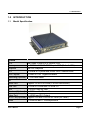
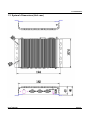
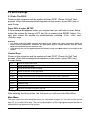
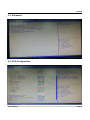
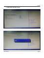
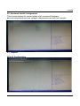
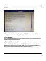
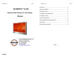
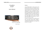
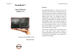
PowerBrick™Ultra
User's Manual
Edition 4.0
Slim and Rugged
Industrial Computer
with Intel® Gen4 Core™ i7-4650U
Acura Embedded Systems Inc.
TABLE OF CONTENTS
1.0
Introduction ..................................................................................................................
1
1.1
Model Specification..................................................................................................
1
1.2
System's I/O...............................................................................................................
2
1.3
System's Dimensions................................................................................................
3
BIOS Settings ................................................................................................................
4
2.1
Enter The BIOS .........................................................................................................
4
2.2
Main.............................................................................................................................
5
2.3
Advanced....................................................................................................................
6
2.4
CPU Configuration.....................................................................................................
6
2.5
Super I/O Configuration ..........................................................................................
7
2.6
Hardware Health Configuration...............................................................................
10
2.7
Chipset ......................................................................................................................
10
2.8
Boot ............................................................................................................................
13
2.9
Security .....................................................................................................................
14
2.10
Exit .............................................................................................................................
15
2.0
User’s Manual
1.0 Introduction
1.0 INTRODUCTION
1.1
Model Specification
System
CPU
Memory
Graphics
ATA
LAN Chipset
Watchdog(Optional)
I/O
Serial Port
USB Port
LAN
Wireless (Optional)
Intel Gen4 /Core i3 or i7-4650U CPU
1 x DDR3L‐1600 SO‐DIMM up to 8GB (Default 4GB)
Intel HD Graphics
2 x Serial ATA ports with 6GB/s HDD Transfer Rate
2 x Intel i210‐AT Gigabit Ethernet
1 ~ 255 level reset
Support 3 x RS‐232 Ports (2 x RS232/422/485)
2 x USB 2.0 Ports and 2 x USB 3.0
2 x RJ45 Ports for GbE
1 x WIFI and 1x Bluetooth
Video Port
1 x HDMI and DVI Output
GPIO Port(Optional) Support 4 In and 4 Out GPIO Ports (5V Level)
1 x Line‐out and 1 x Microphone-in
Audio
User’s Manual
Page 1
1.0 Introduction
Storage
Type
1 x 2.5” drive bay for SATA Type Hard Disk Drive / SSD
1 x SATA DOM
Environment
Relative Humidity
‐30 ~ 60ºC, ambient w/ air
‐40 ~ 85ºC
10 ~ 95% @ 40ºC (non‐condensing)
Power Input
DC 12V Input
Operating Temp.
Storage Temp.
Mechanical
Construction
Mounting
Weight
Dimensions
Aluminum alloy
Wall‐mount
1.2 Kg / 3 LBs
182 x 167.6 x 40 mm
1.2 System's I/O
User’s Manual
Page 2
1.0 Introduction
1.3 System's Dimensions (Unit: mm)
User’s Manual
Page 3
2.0 BIOS
2.0 BIOS Settings
2.1 Enter The BIOS
Power on the computer and the system will start POST (Power On Self Test)
process. When the message below appears on the screen, press (DEL) key to
enter Setup.
Press DEL to enter SETUP
If the message disappears before you respond and you still wish to enter Setup,
restart the system by turning it OFF and On or pressing the RESET button. You
may also restart the system by simultaneously pressing <Ctrl>, <Alt>, and
<Delete> keys.
Important
• The items under each BIOS category described in this chapter are under continuous update for
better system performance. Therefore, the description may be slightly different from the latest
BIOS and should be held for reference only.
• Upon boot‐up, the 1st line appearing after the memory count is the BIOS version. It is usually in the
format.
Control Keys
Power on the computer and the system will start POST (Power On Self Test)
process. When the message below appears on the screen, press (DEL) key
to enter Setup.
<↑>
Move to the previous item
<↓>
Move to the next item
<←>
Move to the item in the left hand
<→>
<Enter>
Move to the item in the right hand
Select the item
<Esc>
Jumps to the Exit menu or returns to the main menu from a submenu
<+/PU>
Increase the numeric value or make changes
<‐/PD>
Decrease the numeric value or make changes
<F1>
General Help
<F3>
Load Optimized Defaults
<F4>
Save all the CMOS changes and exit
Getting Help
After entering the Setup menu, the first menu you will see is the Main Menu.
Main Menu
The main menu lists the setup functions you can make changes to. You can use the arrow
keys (↑↓) to select the item. The on‐line description of the highlighted setup function is
displayed at the bottom of the screen.
User’s Manual
Page4
2.0 BIOS
Sub‐Menu
If you find a right pointer symbol (as shown in the right view) appears to the left of
certain fields that means a sub‐menu can be launched from this field. A sub‐menu
contains additional options for a field parameter. You can use arrow keys ↑↓)to
(
highlight the field and press <Enter> to call up the sub‐menu. Then you can use
the control keys to enter values and move from field to field within a sub‐menu. If
you want to return to the main menu, just press the <Esc >.
General Help <F1>
The BIOS setup program provides a General Help screen. You can call up this
screen from any menu by simply pressing <F1>. The Help screen lists the
appropriate keys to use and the possible selections for the highlighted item. Press
<Esc> to exit the Help screen.
2.2 Main
» System Date
This setting allows you to set the system Date. The time format is <Day>
<Month> <Date> <Year>.
» System Time
This setting allows you to set the system time. The time format is <Hour>
<Minute> <Second>.
User’s Manual
Page 5
2.0 BIOS
2.3 Advanced
2.4 CPU Configuration
User’s Manual
Page 6
2.0 BIOS
» Limit CPUID Maximum
The CPUID instruction of some newer CPUs will return a value greater than
3. The default is Disabled because this problem does not exist in the
Windows series operating systems. If you are using an operating system
other than Windows, this problem may occur. To avoid this problem, enable
this field to limit the return value to 3 or less than 3.
» Intel Virtualization Technology
When this field is set to Enabled, the VMM can utilize the additional hardware
capabilities provided by Vanderpool Technology.
» EIST
This field is used to enable or disable the Intel Enhanced Speed Step
Technology
2.5 Super IO Configuration
» Serial Port 0/1/2/3 Enable or Disable
Select an Enable or Disable for the specified serial ports.
User’s Manual
Page 7
2.0 BIOS
» COM1 RS232/422/485 Select
User’s Manual
Page 8
2.0 BIOS
» COM2 RS232/422/485 Select
User’s Manual
Page 9
2.0 BIOS
2.6 Hardware Health Configuration
These items display the current status of all monitored hardware
devices/components such as voltages, temperatures and all fans' speeds.
2.7 Chipset
PCH‐IO Configuration
User’s Manual
Page 10
2.0 BIOS
System Agent (SA) Configuration
» Graphics Configuration
User’s Manual
Page 11
2.0 BIOS
User’s Manual
Page 12
2.0 BIOS
2.8 Boot
» 1st/2nd/3rd Boot Device
The items allow you to set the sequence of boot devices where BIOS
attempts to load the disk operating system.
» Try Other Boot Devices
Setting the option to [Enabled] allows the system to try to boot from other
device if the system fail to boot from the 1st/2nd/3rd boot device.
» Hard Disk Drives, CD/DVD Drives, USB Drives
These settings allow you to set the boot sequence of the specified devices.
User’s Manual
Page 13
2.0 BIOS
2.9 Security
» Administrator Password
Administrator Password controls access to the BIOS Setup utility. These
settings allow you to set or change the administrator password.
» User Password
User Password controls access to the system at boot. These settings allow you
to set or change the user password.
» Boot Sector Virus Protection
This function protects the BIOS from accidental corruption by unauthorized users
or computer viruses. When enabled, the BIOS data cannot be changed when
attempting to update the BIOS with a Flash utility. To successfully update the
BIOS, you will need to disable this Flash Protection function.
User’s Manual
Page 14
2.0 BIOS
2.10 Exit
» Save Changes and Exit
Save changes to CMOS and exit the Setup Utility.
» Discard Changes and Exit
Abandon all changes and exit the Setup Utility.
» Discard Changes
Abandon all changes and continue with the Setup Utility.
» Load Optimal Defaults
Use this menu to load the default values set by the mainboard manufacturer
specifically for optimal performance of the mainboard.
» Load Failsafe Defaults
Use this menu to load the default values set by the BIOS vendor for stable system
performance.
User’s Manual
Page 15
With the unique set of products, Acura Embedded Systems remains committed to its goal of
providing trouble-free and customer-friendly service. A special customer service unit has
been set up specifically to cater to our esteemed customers' needs.
Technical Support:
For technical support contact your Salesperson
[email protected]
Mailing Address:
Acura Embedded Systems Inc.
Unit #1, 7711-128th Street, Surrey, BC V3W 4E6, CANADA
Ph: (604) 502-9666 Fax: (604) 502-9668
Toll Free 1-866-502-9666