1
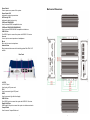
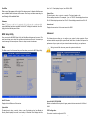
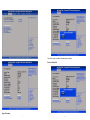
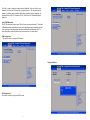
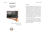
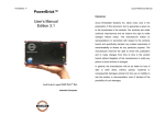
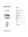
PowerBrick ATOM Contents Quick Manual Chapter 1: Product Introduction Overview ........................................................... 1 Key Features ....................................................... 1 Hardware Specifications .......................................... 1 Knowing Your PowerBrick ATOM .............................. 2 Mechanical Dimensions .......................................... 4 Chapter 2: BIOS Setup About BIOS Setup ................................................. 5 When to Configure the BIOS ..................................... 5 Default Configuration ............................................. 6 Entering Setup ..................................................... 6 BIOS Setup Utility ................................................. 7 Main ................................................................. 7 Advanced ........................................................... 8 Chipset.............................................................. 16 Boot ................................................................. 20 Security ............................................................. 21 Save & Exit ......................................................... 22 Appendix :Power Consumption................................................23 Service Contact Information .................................................. 24 ACURA EMBEDDED SYSTEMS INC. Chapter 1: Product Introduction Overview I/O Interface-Rear ▪ ▪ ▪ ▪ ▪ ▪ ▪ 2x Intel® 82574L GbE LAN port 4x USB2.0 port 1x HDMI 1x DVI-I (support VGA & DVI-D display via cable) 1x 2-pin DC input, Support 9-36V DC input 1x external screwed type CFast socket 1x mini-PCIe socket (support optional Wi-Fi or 3.5G module) Power Requirements ▪ Support 9-36V DC input ▪ 1x optional 12V, 60W power adapter Key Features • • • • • • • • • • On-board Intel® Atom™ Dual Core D2550 processor, 1.86 GHz Intel® NM10 Express chipset 1x DVI-I & 1x HDMI display output Dual Intel® 82574L GbE LAN ports 2x RS232/422/485 and 2x RS232 6x USB2.0 1x external CFast socket 1x mini-PCIe with two antenna holes Support 9-36V DC input Supports ATX power mode, WoL, LAN teaming and PXE function Hardware Specifications CPU Support ▪ ▪ On-board Intel® Atom™ Dual Core processor D2550, 1.86 GHz, 1M L2 cache Intel® NM10 Express chipset ▪ 185mm(W) x 131mm(D) x 54mm(H) (7.28”x 5.2”x 2.13”) Construction ▪ Aluminum chassis with fan less design Environment ▪ Operating temperature: Ambient with air flow: -5°C ~ 55°C (according to IEC60068-2-1, IEC60068-2-2, IEC60068-2-14) ▪ Storage temperature: -20°C ~ 80°C ▪ Relative humidity: 10% to 93% (non-Condensing) ▪ Shock protection: 20G, half sine, 11ms, IEC60068-2-27 ▪ Vibration protection Random: 0.5Grms @5~500 Hz according to IEC68-2-64 Sinusoidal: 0.5Grms @5~500 Hz according to IEC68-2-6 Certifications ▪ CE approval ▪ FCC Class A Main Memory • Dimensions 1x DDR3 SO-DIMM sockets, support up to 4G DDR3-800/1066 SDRAM, unbuffered and non-ECC Knowing Your PowerBrick ATOM I/O Interface-Front • • • • • • ATX power on/off switch HDD access/power status LEDs 4x COM ports (COM2 & 3: RS232/422/485) 2x USB2.0 port Audio jack (speaker-out & mic-in) 2x antenna holes Device • 1x 2.5” HDD drive bay • 1x External CFast Socket 1 2 Front Panel Power Switch Press to power-on or power-off the system. Power Status LED Indicates the system’s power status. HDD Activity LED Indicates the hard drive’s activity. COM1 and COM4 RS232 Used to connect RS232 compatible devices. COM2 and COM3 RS232/RS422/RS485 Used to connect RS232/422/485 compatible serial devices. USB2.0 Ports Two USB2.0 ports to connect the system with USB2.0/1.1 devices. Line-out Line-out jack to connect speakers or headphones. Mic-in Mic-in jack to connect microphones. Antenna Holes Empty antenna holes reserved for installing optional Mini-PCIe Wi-Fi module. Mechanical Dimensions Rear Panel 9~36 DC 9~36V DC Input Used to plug a DC power cord. DVI-I Used to connect a digital LCD panel. HDMI Used to connect a high-definition display. USB2.0 Ports Four USB2.0 ports to connect the system with USB2.0/1.1 devices. Gigabit LAN Ports Dual Gigabit LAN ports to connect the system to a local area network. CompactFlash Used to insert a CompactFlash card. 3 4 Default Configuration Chapter 2: BIOS Setup This chapter describes how to use the BIOS setup program for the PowerBrick ATOM. The BIOS screens provided in this chapter are for reference only and may change if the BIOS is updated in the future. Most of the configuration settings are either predefined according to the Load Optimal Defaults settings which are stored in the BIOS or are automatically detected and configured without requiring any actions. There are a few settings that you may need to change depending on your system configuration. To check for the latest updates and revisions, visit www.acuraembedded.com. Entering Setup About BIOS Setup When the system is powered on, the BIOS will enter the Power-On Self Test (POST) routines. These routines perform various diagnostic checks; if an error is encountered, the error will be reported in one of two different ways: • If the error occurs before the display device is initialized, a series of beeps will be transmitted. • If the error occurs after the display device is initialized, the screen will display the error message. Powering on the computer and immediately pressing <Del> allows you to enter Setup. Another way to enter Setup is to power on the computer and wait for the following message during the POST: TO ENTER SETUP BEFORE BOOT PRESS <CTRL-ALT-ESC> Press the <Del> key to enter Setup: The BIOS (Basic Input and Output System) Setup program is a menu driven utility that enables you to make changes to the system configuration and tailor your system to suit your individual work needs. It is a ROM-based configuration utility that displays the system’s configuration status and provides you with a tool to set system parameters. These parameters are stored in non-volatile battery-backed-up CMOS RAM that saves this information even when the power is turned off. When the system is turned back on, the system is configured with the values found in CMOS. With easy-to-use pull down menus, you can configure such items as: • Hard drives, diskette drives, and peripherals • Video display type and display options • Password protection from unauthorized use • Power management features The settings made in the setup program affect how the computer per-forms. It is important, therefore, first to try to understand all the setup options, and second, to make settings appropriate for the way you use the computer. When to Configure the BIOS This program should be executed under the following conditions: ▪When changing the system configuration • When a configuration error is detected by the system and you are prompted to make changes to the setup program • When resetting the system clock • When redefining the communication ports to prevent any conflicts ▪When making changes to the Power Management configuration • When changing the password or making other changes to the security setup Normally, CMOS setup is needed when the system hardware is not consistent with the information contained in the CMOS RAM, whenever the CMOS RAM has lost power, or the system features need to be changed. 5 Key Function Right and Left arrows Moves the highlight left or right to select a menu. Up and Down arrows Moves the highlight up or down between sumenus or fields. <Esc> Exits the BIOS Setup Utility. + (plus key) Scrolls forward through the values or options of the highlighted field. - (minus key) Scrolls backward through the values or options of the highlighted field. Tab Selects a field. <F1> Displays General Help. <F2> Load previous values <F3> Load optimized default values. <F4> Saves and exits the Setup program. <Enter> Press <Enter> to enter the highlighted submenu. 6 Scroll Bar When a scroll bar appears to the right of the setup screen, it indicates that there are more available fields not shown on the screen. Use the up and down arrow keys to scroll through all the available fields. from 1 to 31. Year displays the year, from 1999 to 2099. System Time The time format is <hour>, <minute>, <second>. The time is based on the 24-hour military-time clock. For example, 1 p.m. is 13:00:00. Hour displays hours from 00 to 23. Minute displays minutes from 00 to 59. Second displays seconds from 00 to 59. Submenu When ““a ppe a rs on the le ft of a pa rticula r fie ld, it indica te s tha t a s ubm e nu which contains additional options are available for that field. To display the submenu, move the highlight to that field and press <Enter>. Access Level Displays the access level of the current user in the BIOS. Advanced BIOS Setup Utility Once you enter the AMI BIOS Setup Utility, the Main Menu will appear on the screen. The main menu allows you to select from several setup functions and one exit. Use arrow keys to select among the items and press <Enter> to accept or enter the submenu. Main The Advanced menu allows you to configure your system for basic operation. Some entries are defaults required by the system board, while others, if enabled, will improve the performance of your system or let you set some features according to your preference. Setting incorrect field values may cause the system to malfunction. The Main menu is the first screen that you will see when you enter the BIOS Setup Utility. Intel RC Version Displays the Intel Reference Code version. Launch LAN1/2 PXE OpROM Enables or disables the boot option for legacy network devices connected to LAN1 and LAN2. System Date The date format is <day>, <month>, <date>, <year>. Day displays a day, from Monday to Sunday. Month displays the month, from January to December. Date displays the date, 7 CPU Configuration This section is used to configure the CPU. 8 This field is used to enable or disable hyper-threading. Execute Disable Bit Hyper-Threading 9 10 This field is used to enable or disable execute disable bit. When this field is set to Disabled, it will force the XD feature flag to always return to 0. XD can prevent certain classes of malicious buffer overflow attacks when combined with a supporting OS (Windows Server 2003 SP1, Windows XP SP2, SuSE Linux 9.2, RedHat Enterprise 3 Update 3). Limit CPUID Maximum The CPUID instruction of some newer CPUs will return a value greater than 3. The default is Disabled because this problem does not exist in the Windows series operating systems. If you are using an operating system other than Windows, this problem may occur. To avoid this problem, enable this field to limit the return value to 3 or lesser than 3. USB Configuration This section is used to configure USB devices. Configure SATA as IDE Configuration This section is used to configure the IDE devices. 11 12 Configures the SATA as IDE or AHCI mode. • IDE • AHCI This option configures the Serial ATA drives as Parallel ATA physical storage device. This option configures the Serial ATA drives to use AHCI (Advanced Host Controller Interface). AHCI allows the storage driver to enable the advanced Serial ATA features which will increase storage performance. SATA Controller(s) Enables or disables SATA controller. Super IO Configuration This section is used to configure the I/O board Super I/O chip. This field configures the maximum baud rate of the serial port 0, the options are 115200 bps and 921600 bps. Onboard Serial Port Mode Serial Port 0 Configuration This field is used to configure the mode of serial port 1 as RS232, RS422, RS485 or RS485 AUTO. 13 14 Onboard Serial Port Max Baud Rate PPM Configuration This section is used to configure Intel SpeedStep. This field configures the maximum baud rate of the serial port 1, the options are 115200 bps and 921600 bps. H/W Monitor This section is used to configure the hardware temperature, fan speed and voltages. Chipset This section is used to configure the system based on the specific features of the chipset. 15 16 IGFX – Boot Type Setting incorrect field values may cause the system to malfunction. This field is used to configure which video device will be activated during POST. This has no effect if external graphics present. The options are CRT, DVI and CRT + HDMI. Host Bridge Displays the memory information Due to Intel® VBIOS wrong address issue in HDMI mode, thereis no “HDMI” display output option in the BIOS menu. Please refer to the following table for the display reference when a HDMI monitor is connected to POWERBRICK ATOM. Fixed Graphics Memory Size Intel® IGD Configuration Settings for Intel® IGD. 17 18 SMBus Controller This section is used to configure SMBus. High Precision Timer This section is used to configure High Precision Event Timer. Restore AC Power Loss This section is used to configure Restore AC Power Loss. This field is used to configure the memory size of the fixed graphics, the options are 128MB and 256MB. South Bridge This field is used to configure the AC power state when power is restored after power failure, the options are Power Off and Power On. Boot Boot Configuration This section is used to configure settings during sytem boot. Setup Prompt Timeout This section configures the number of seconds to wait for the setup activation key. Quiet Boot When Enabled, the BIOS will shorten or skip some check items during POST. This will decrease the time needed to boot the system. GateA20 Active Configures the GateA20 function. Option ROM Messages Configures the ROM message. Interrupt 19 Capture When enabled, it allows the optional ROM to trap interrupt 19. Boot Option Priorities Azalia Controller This section disables Azalia or enables HD Audio. 19 20 Boot option #1 Administrator Password Sets the administrator’s password User Password Sets the user’s password. Save & Exit This field is used to adjust the boot sequence of the system. Boot Option #1 is the first boot device that the system will boot from, next will be #2 and so forth. Security Save Changes and Exit To save the changes and exit the Setup utility, select this field then press <Enter>. A dialog box will appear. Confirm by selecting Yes. You can also press <F4> to save and exit Setup. Discard Changes and Exit To exit the Setup utility without saving the changes, select this field then press <Enter>. You may be prompted to confirm again before exiting. You can also press <ESC> to exit without saving the changes. Save Changes and Reset To save the changes and reset, select this field then press <Enter>. A dialog box will appear. Confirm by selecting Yes. Discard Changes and Reset To exit the Setup utility without saving the changes, select this field then press <Enter>. You may be prompted to confirm again before exiting. Save Changes To save changes and continue configuring the BIOS, select this field then press <Enter>. A dialog box will appear. Confirm by selecting Yes. Discard Changes To discard the changes, select this field then press <Enter>. A dialog box will appear. 21 22 Confirm by selecting Yes to discard all changes made and restore the previously saved settings. Restore Defaults To restore the BIOS to default settings, select this field then press <Enter>. A dialog box will appear. Confirm by selecting Yes. Save as User Defaults To use the current configurations as user default settings for the BIOS, select this field then press <Enter>. A dialog box will appear. Confirm by selecting Yes. Restore User Defaults To restore the BIOS to user default settings, select this field then press <Enter>. A dialog box will appear. Confirm by selecting Yes. Boot Override To bypass the boot sequence from the Boot Option List and boot from a particular device, select the desired device and press <Enter>. Launch EFI Shell from filesystem device To launch EFI shell from a filesystem device, select this field and press <Enter>. Service Contact Information Acura Embedded Systems Inc. #1 7711 128 Street Surrey, BC V3W 4E6 Canada. Tel: 604.502.9666 support@ acuraembedded.com www. acuraembedded.com Appendix : Power Consumption Power Consumption Measurement Purpose The purpose of the power consumption test is to verify the power dissipation of system, and the loading of power supply. Test Equipment PROVA CM-07 AC/DC CLAMP METER Test Procedure 1.Power up the DUT, boot into Windows 7 x32 Ultimate. 2.Entering standby mode (HDD power down). 3.Measure the power consumption and record it. 4.Run Burn-in test program to apply 100% full loading. 5.Measure the power consumption and record it. Test Data 23 24