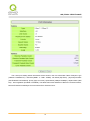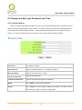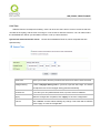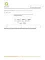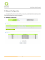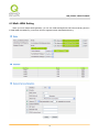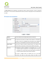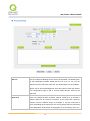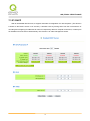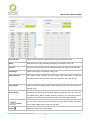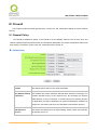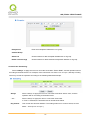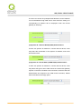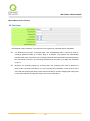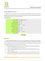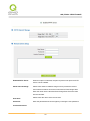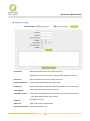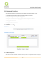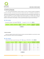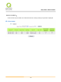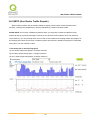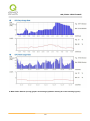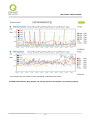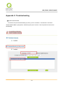
1
SSL/IPSec VPN Firewall 4WAN 4LAN SSL/ IPSec VPN Firewall Load Balance, Bandwidth Management, and Network Security English User’s Manual 1 SSL/IPSec VPN Firewall Content I. Introduction ............................................................................................................................................... 7 II. Multi-WAN Router Installation ............................................................................................................. 10 2.1 Systematic Setting Process ........................................................................................................... 10 2.2 Setting Flow Chart ........................................................................................................................... 10 III. Hardware Installation ........................................................................................................................... 13 3.1 Router LED Signal ........................................................................................................................... 13 3.2 Router Network Connection ........................................................................................................... 15 IV. Login Router ........................................................................................................................................... 16 V. Device Spec Verification, Status Display and Login Password and Time Setting .............................. 18 5.1 Home Page ....................................................................................................................................... 18 5.1.1 WAN Status .............................................................................................................................................. 18 5.1.2 Physical Port Status.................................................................................................................................. 19 5.1.3 System Information .................................................................................................................................. 21 5.1.4 Firewall Status ......................................................................................................................................... 22 5.1.5 Log Setting Status .................................................................................................................................... 22 5.2 Change and Set Login Password and Time ................................................................................. 24 5.2.1 Password Setting ...................................................................................................................................... 24 5.2.2 Time ......................................................................................................................................................... 25 VI. Network Configuration.......................................................................................................................... 27 6.1 Network Connection ....................................................................................................................... 27 6.1.1 Host Name and Domain Name ................................................................................................................ 28 6.1.2 LAN Setting ............................................................................................................................................. 28 6.1.3 WAN & DMZ Settings ............................................................................................................................. 29 6.2 Multi- WAN Setting .......................................................................................................................... 45 6.2.1 Load Balance Mode ................................................................................................................................. 46 6.2.2 Network Detection Service ...................................................................................................................... 53 6.2.3 Protocol Binding ...................................................................................................................................... 56 VII. Intranet Configuration ......................................................................................................................... 68 7.1 Port Management ............................................................................................................................ 68 7.2 Port Status ....................................................................................................................................... 69 7.3 IP/ DHCP ........................................................................................................................................... 71 7.4 DHCP Status .................................................................................................................................... 73 7.5 IP & MAC Binding ............................................................................................................................ 76 7.6 IP Group Management .................................................................................................................... 80 1 SSL/IPSec VPN Firewall 7.7 Port Group Management ................................................................................................................ 82 VIII. QoS (Quality of Service) ..................................................................................................................... 85 8.1 Bandwidth Management (QoS) ...................................................................................................... 85 8.1.1 Bandwidth Management .......................................................................................................................... 87 8.1.2 QoS .......................................................................................................................................................... 87 8.1.3 Smart QoS ................................................................................................................................................ 91 8.1.4 Bandwidth Management Scheduling ....................................................................................................... 92 8.1.5 Exception IP address ................................................................................................................................ 93 8.2 Session control................................................................................................................................ 94 8.3 Hardware Optimization (Future Feature) ...................................................................................... 98 IX. Firewall ................................................................................................................................................. 100 9.1 General Policy................................................................................................................................ 100 9.2 Access Rule ................................................................................................................................... 107 9.2.1 Default Access Rule ............................................................................................................................... 107 9.2.2 Add New Access Rule ............................................................................................................................ 109 9.3 Content Filter ................................................................................................................................. 111 X. VPN (Virtual Private Network) ............................................................................................................ 117 10.1 VPN ............................................................................................................................................... 117 10.1.1. Display All VPN Summary ................................................................................................................. 117 10.1.2. Add a New VPN Tunnel...................................................................................................................... 121 10.1.3. PPTP Setting ....................................................................................................................................... 149 10.1.4. VPN Pass Through .............................................................................................................................. 152 10.2. QnoKey ........................................................................................................................................ 153 10.2.1. QnoKey Summary .............................................................................................................................. 153 10.2.2 Qnokey Group Setup ............................................................................................................................ 154 10.2.3 Qnokey Account List ........................................................................................................................... 157 10.3. QVM VPN Function Setup .......................................................................................................... 159 10.3.1. QVM Server Settings .......................................................................................................................... 159 10.3.2. QVM Status ........................................................................................................................................ 161 10.3.3. QVM Client Settings (Future Feature) ................................................................................................ 162 XI. SSL VPN................................................................................................................................................ 164 11.1 Status ............................................................................................................................................ 164 11.2 Group Summary .......................................................................................................................... 165 11.3 Group Management ..................................................................................................................... 166 11.4 Domain Management .................................................................................................................. 185 2 SSL/IPSec VPN Firewall 11.5 User Management ........................................................................................................................ 186 11.6 Service Resource Management ................................................................................................. 189 11.6.1 Banner .................................................................................................................................................. 190 11.6.2 Resource Configuration ....................................................................................................................... 190 11.7 Link to Portal ................................................................................................................................ 192 11.8 Advanced Settings ...................................................................................................................... 193 11.8.1 Virtual Passage ..................................................................................................................................... 194 11.8.2 Advanced Configurations ..................................................................................................................... 196 11.8.3 SSL Upgrade Serial Number ................................................................................................................ 199 XII. Advanced Function ............................................................................................................................. 200 12.1 DMZ/Forwarding .......................................................................................................................... 200 12.1.1 DMZ Configuration ............................................................................................................................. 200 12.1.2 Port Range Forwarding ........................................................................................................................ 201 12.2 UPnP ............................................................................................................................................. 204 12.3 Routing ......................................................................................................................................... 205 12.3.1 Dynamic Routing ................................................................................................................................. 206 12.3.2 Static Routing ...................................................................................................................................... 206 12.4 One to One NAT ........................................................................................................................... 208 12.5 DDNS- Dynamic Domain Name Service .................................................................................... 212 12.6 MAC Clone ................................................................................................................................... 214 12.7 Inbound Load Balance ................................................................................................................ 215 XIII. System Tool ........................................................................................................................................ 223 13.1 Diagnostic .................................................................................................................................... 223 13.2 Firmware Upgrade ....................................................................................................................... 224 13.3 Configuration Backup ................................................................................................................. 225 13.4 SNMP ............................................................................................................................................ 226 13.5 System Recover .......................................................................................................................... 227 13.6 High Availability ........................................................................................................................... 229 11.7 License Key .................................................................................................................................. 234 XIV. Log....................................................................................................................................................... 236 14.1 System Log .................................................................................................................................. 236 14.2 System Statistic ........................................................................................................................... 240 14.3 Traffic Statistic ............................................................................................................................. 241 14.4 Connection Statistic (Future Feature) ....................................................................................... 245 14.5 IP/ Port Statistic ........................................................................................................................... 247 3 SSL/IPSec VPN Firewall 14.6 QRTG (Qno Router Traffic Graphic) .......................................................................................... 249 XV. Log out.................................................................................................................................................. 254 Appendix I: User Interface and User Manual Chapter Cross Reference .............................................. 255 Appendix II: Troubleshooting ................................................................................................................... 259 (1) Block BT Download .................................................................................................................... 259 (2) Shock Wave and Worm Virus Prevention .................................................................................. 260 (3) Block QQLive Video Broadcast Setting ...................................................................................... 262 (4) ARP Virus Attack Prevention ...................................................................................................... 264 Appendix III: Qno Technical Support Information .............................................................................. 273 4 SSL/IPSec VPN Firewall Product Manual Using Permit Agreement [Product Manual (hereafter the "Manual") Using Permit Agreement] hereafter the "Agreement" is the using permit of the Manual, and the relevant rights and obligations between the users and Qno Technology Inc (hereafter "Qno"), and is the exclusion to remit or limit the liability of Qno. The users who obtain the file of this manual directly or indirectly, and users who use the relevant services, must obey this Agreement. Important Notice: Qno would like to remind the users to read the clauses of the "Agreement" before downloading and reading this Manual. Unless you accept the clauses of this "Agreement", please return this Manual and relevant services. The downloading or reading of this Manual is regarded as accepting this "Agreement" and the restriction of clauses in this "Agreement". 【1】Statement of Intellectual Property Any text and corresponding combination, diagram, interface design, printing materials or electronic file are protected by copyright of our country, clauses of international copyright and other regulations of intellectual property. When the user copies the "Manual", this statement of intellectual property must also be copied and indicated. Otherwise, Qno regards it as tort and relevant duty will be prosecuted as well. 【2】Scope of Authority of "Manual" The user may install, use, display and read this "Manual on the complete set of computer. 【3】User Notice If users obey the law and this Agreement, they may use this "Manual" in accordance with "Agreement". The "hardcopy or softcopy" of this Manual is restricted using for information, non-commercial and personal purpose. Besides, it is not allowed to copy or announce on any network computer. Furthermore, it is not allowed to disseminate on any media. It is not allowed to modify any part of the "file". Using for other purposes is prohibited by law and it may cause serious civil and criminal punishment. The transgressor will receive the accusation possibly. 【4】Legal Liability and Exclusion 【4-1】Qno will check the mistake of the texts and diagrams with all strength. However, Qno, distributors, and resellers do not bear any liability for direct or indirect economic loss, data loss or other corresponding commercial loss to the user or relevant personnel due to the possible omission. 【4-2】In order to protect the autonomy of the business development and adjustment of Qno, Qno reserves 5 SSL/IPSec VPN Firewall the right to adjust or terminate the software / Manual any time without informing the users. There will be no further notice regarding the product upgrade or change of technical specification. If it is necessary, the change or termination will be announced in the relevant block of the Qno website. 【4-3】All the set parameters are examples and they are for reference only. You may also purpose your opinion or suggestion. We will take it as reference and they may be amended in the next version. 【4-4】This Manual explains the configuration of all functions for the products of the same series. The actual functions of the product may vary with the model. Therefore, some functions may not be found on the product you purchased. 【4-5】Qno reserves the right to change the file content of this Manual and the Manual content may not be updated instantly. To know more about the updated information of the product, please visit Qno official website. 【4-6】Qno (and / or) distributors hereby declares that no liability will be born for any guarantee and condition of the corresponding information. The guarantee and condition include tacit guarantee and condition about marketability, suitability for special purposes, ownership, and non-infringement. The name of the companies and products mentioned may be the trademark of the owners. Qno (and/or) the distributors do not provide the product or software of any third party company. Under any circumstance, Qno and / or distributors bear no liability for special, indirect, derivative loss or any type of loss in the lawsuit caused by usage or information on the file, no matter the lawsuit is related to agreement, omission, or other tort. 【5】Other Clauses 【5-1】The potency of this Agreement is over any other verbal or written record. The invalidation of part or whole of any clause does not affect the potency of other clauses. 【5-2】The power of interpretation, potency and dispute are applicable for the law of Taiwan. If there is any dissension or dispute between the users and Qno, it should be attempted to solve by consultation first. If it is not solved by consultation, user agrees that the dissension or dispute is brought to trial in the jurisdiction of the court in the location of Qno. In Mainland China, the "China International Economic and Trade Arbitration Commission" is the arbitration organization. 6 SSL/IPSec VPN Firewall I. Introduction New generation SSL/ IPSec VPN Firewall is a high efficiency router owing to the market requirement. It is designed as economical, high efficiency with all functions integrated for network VPN Router that fulfills the requirement of enterprise branches, vendors and SOHO for VPN application increase and bandwidth management. New generation SSL/ IPSec VPN Router focuses on multiple ISP environment and user bandwidth management requirement to integrate the backbone networking, it can support hardware port mirror, smart QoS, Multi-WAN load balance, gateway redundancy, and Intelligent Firewall. SSL/ IPSec VPN Router uses a 64-bit high-level processor and maximum 200 Mbps-two way forwarding rate that can support several hundred thousand session connections, built-in high- capacity RAM allows the stability and reliability for long-time operation. It has 4 10/100 Base-T/TX Ethernets (RJ45) WAN ports. These WAN ports can support auto load balance mode, exclusive mode (remaining WAN balance), and stategy routing mode for high-efficiency network. They offer super flexibility for network set-up. Moreover, these WAN ports also support DHCP, fixed IP, PPPoE, transparent bridge, VPN connection, port binding, static routing, dynamic routing, NAT, one to one NAT, PAT, MAC Clone, as well as DDNS. As for LAN ports including one DMZ, they support 10/100 Base-T/TX Ethernet (RJ45) and provide the features of Microsoft UPnP, VLAN, Multi Subnet, and transparent bridge mode. Internet IP addresses can also be used in intranet. Individual QoS bandwidth management with powerful and easy-to-setup functions allows manager to arrange the limited network resource rational and efficiently. It is not needed to extend the bandwidth to unlimited settings which would increase spending cost; it can also avoid the complaint of few people to force whole bandwidth. Simple user configuration can be the best efficiency application; it allows the optimization of bandwidth utilization based on the whole utility rate without setting rules step-by-step and only to limit the users who occupy the bandwidth for resource savings. Moreover, intelligence bandwidth management is provided, through the simple deployment to complete LAN side bandwidth management for efficiency utility rate, simple management and improvement performance. SSL/IPSec VPN Router exclusively provides hardware optimization, which can run broadbandwidth management, traffic priorities and distributions directly through hardware. Not only can it ensure intranet important services won’t have disconnection, but also decrease the depletion of CPU and the whole system resources. Thus, SSL/IPSec VPN Router can endure enormous sessions and PCs, and provide stable network environment. Load balancing function supports Auto Load Balance mode, Specify WAN Binding mode and Strategy 7 SSL/IPSec VPN Firewall Routing mode to allow deployment of flexible network connection required to control traffic flow to guarantee that whole connections are unobstructed. Strategy Routing mode is simply to configure the network without the input of IP address. It can automatically detect outbound packets and filter telecom connection to ensure quick response and packet pass through without obstruction, and it can aggregate the same ISP bandwidth for load balancing control and increase flexibility of network resource. Built-in Firewall system can fulfill market requirement in defense of internet attacks for most enterprise. Initiative packet inspection via the network layer dynamic detection denies or blocks non-standard protocol connections. It can easily employ complete protection functions to ensure network security, as required for any kind of hack attacks, worm & Virus and ARP attacks by one-way control. Firewall system has not only NAT function but also DoS attack. Complete Functions of Access Rules can allow managers to select the network service levels to deny or allow accesses, and it can also limit or deny LAN users to use the network and to avoid the network resource being occupied or threatened due to improper uses. NAT function can provide the translation between private IP and public IP, which can allow multi-user to connect the internet with one public IP at the same time. LAN IP supports four Class C connections, and DHCP server is also supported, as well as an easy configuration of IP-MAC binding function allowing network structure to be flexible and easy to deployed and managed. In addition, SSL/ IPSec VPN Router also supports virtual routing function. One-WAN branch can be upgraded to dual-WAN transmit ion easily, Enterprise with one-WAN can connect to dual-WAN center by easy configuration and traffic will pass through other WAN lines from the center network. This can also accelerate the connections among different areas to solve the connection bottleneck problem. For SSL VPN, client only need a web browser to access to Central servers. Passing the ID, and you get the portal to the company’s internal resources, such as Internet services, Microsoft terminal services, remote desktop services, online neighborhood networks, and secure tunnel functions. Meanwhile, different users or groups can access to different interfaces according to the web administrator’s configurations, which satisfies external and mobile users' security requirements. Qno is a supporter of the IPSec Protocol. IPSec VPN provides DES, 3DES, AES-128 encryption, MD5, SH1 certification, IKE Pre-Share Key, or manual password interchange. SSL/ IPSec VPN Router also supports aggressive mode. When a connection is lost, SSL/ IPSec VPN Router will automatically re-connect. In addition, SSL/ IPSec VPN Router features NetBIOS transparency, and supports IP grouping for connections between clients and host in the virtual private network. SSL/ IPSec VPN Router offers the function of a standard PPTP server, which is equipped with connection setting status. Each WAN port can be set up with multiple DDNS at the same time. It is also 8 SSL/IPSec VPN Firewall capable of establishing VPN connections with dynamic IP addresses. SSL/ IPSec VPN Router also has unique QVM VPN- SmartLink IPSec VPN. Just input VPN server IP, user name, and password, and IPSec VPN will be automatically set up. Through SSL/IPSec VPN Router exclusive QVM function, users can set up QVM to work as a server, and have it accept other QVM series products from client ports. QVM offers easy VPN allocation for users; users can do it even without a network administrator. SSL/ IPSec VPN Router enables enterprises to benefit from VPN without being troubled with technical and network management problems. The central control function enables the host to log in remote client computers at any time. Security and secrecy are guaranteed to meet the IPSec standard, so as to ensure the continuity of VPN service. You can log on to our Web site www.Qno.com.tw, and find the latest Qno product information and technical support. The device is an FCC Class A product, it may cause radio interference in the living environment. User may need to take feasible measures in this condition. 9 SSL/IPSec VPN Firewall II. Multi-WAN Router Installation In this chapter we are going to introduce hardware installation. Through the understanding of multi- WAN setting process, users can easily setup and manage the network,making Router functioning and having best performance. 2.1 Systematic Setting Process Users can set up and enable the network by utilizing bandwidth efficiently. The network can achieve the ideal efficientness,block attacks, and prevent security risks at the same time. Through the process settings, users can install and operate Router easily. This simplifies the management and maintenance, making the user network settings be done at one time. The main process is as below: 1. Hardware installation 2. Login 3. Verify device specification and set up password and time 4. Set WAN connection 5. Set LAN connection: physical port and IP address settings 6. Set QoS bandwidth management: avoid bandwidth occupation 7. Set Firewall: prevent attack and improper access to network resources 8. Other settings: UPnP, DDNS, MAC Clone 9. Management and maintenance settings: Syslog, SNMP, and configuration backup 10. VPN Virtual Private Network, QnoKey, QVM, SSL VPN function setting 11. Logout 2.2 Setting Flow Chart Below is the description for each setting process, and the crospondent contents and purposes. detailed functions, please refer to Appendix I: Setting Inferface and Chapter Index. 10 For SSL/IPSec VPN Firewall # 1 Setting Hardware installation Content Purpose Configure the Install VPN Router hardware based on user network to meet physical requirements. user’s demand. 2 Login Login the device with Login VPN Router web- based UI. Web Browser. 3 Verify device Verify Firmware Verify VPN Router specification, Firmware specification version and working version and working status. status. Set password and time Set time and re- new Modify the login password considering safe password. issue. Synchronize VPN Router time with WAN. 4 Set WAN connection Verify WAN Connect to WAN. Configure bandwidth to connection setting, optimize data transmission. bandwidth allocation, and protocol binding. 5 Set LAN connection: physical port and IP address settings 6 Set QoS bandwidth management: avoid bandwidth occupation 7 Set Firewall: prevent attack and improper access to network Set mirror port and Provide mirror port, port management and VLAN. Allocate and VLAN setting functions. Support Static/DHCP manage LAN IP. IP allocation to meet different needs. IP group will simplify the management work. Restrict bandwidth To assure transmission of important and session of WAN information, manage and allocate the ports, LAN IP and bandwidth further to achieve best efficiency. application. Block attack, Set Administrators can block BT to avoid bandwidth Access rule and occupation, and enable access rules to restrict restrict Web access. employee accessing internet improperly or using MSN, QQ and Skype during working resources time. They can also protect network from Worm or ARP attacking. 11 SSL/IPSec VPN Firewall 8 Advanced Settings: DMZ/Forwarding, DMZ/Forwarding, UPnP, Routing Mode, DMZ/Forwarding, UPnP, Routing Mode, multiple WAN IP, DDNS and MAC Clone UPnP, DDNS, MAC multiple WAN IP, Clone DDNS and MAC Clone 9 Management and maintenance settings: Syslog, SNMP, and Monitor working Administrators can look up system log and status and monitor system status and inbound/outbound configuration backup. flow in real time. Configure VPN Configure different types of VPN to meet tunnels, e.g. PPTP, different application environment. configuration backup 10 VPN Virtual Private Network, QnoKey, QVM VPN function setting 11 Logout QnoKey, QVM and SSL VPN. Close configuration Web- based UI logout. window. We will follow the process flow to complete the network setting in the following chapters. 12 SSL/IPSec VPN Firewall III. Hardware Installation In this chapter we are going to introduce hardware interface as well as physical installation. 3.1 Router LED Signal LED Signal Description LED Color Description Power Green Green LED on: Power ON DIAG Amber Amber LED on: System self-test is running. Amber LED off: System self-test is completed successfully. Link/Act Green Green LED on: Ethernet connection is fine. Green LED blinking: Packets are transmitting through Ethernet port. Amber Amber LED on: Ethernet is running at 100Mbps. Amber LED off: Ethernet is running at 10Mbps. Green Green LED on: WAN is connected and gets the IP address. (Green light at the right of the port) 100M- Speed (Amber light at th left of the port) Connect Reset Action Description Press Reset Button For 5 Secs Warm Start DIAG indicator: Amber LED flashing slowly. Press Reset Button Over 10 Secs Factory Default DIAG indicator: Amber LED flashing quickly. System Built-in Battery A system timing battery is built into life is over or it can not be charged, Router. The lifespan of the battery is about 1~2 years. If the battery Router will not be able to record time correctly, nor synchronize with internet NTP time server. Please contact your system supplier for information on how to replace the battery. Attention! Do not replace the battery yourself; otherwise irreparable damage to the product may be caused. 13 SSL/IPSec VPN Firewall Installing Router on a Standard 19” Rack We suggest to either place Router on a desk or install it in a rack with attached brackets. Do not place other heavy objects together with Router on a rack. Overloading may cause the rack to fail, thus causing damage or danger. Each Router comes with a set of rack installation accessories, including 2 L- shaped brackets and 8 screws. Users can rack- mount the device onto the chassis. Please refer to the figure below for the installation onto a 19‖ rack: Attention! In order for the device to run smoothly, wherever users install it, be sure not to obstruct the vent on each side of the device. Keep at least 10cm space in front of both the vents for air convection. 14 SSL/IPSec VPN Firewall 3.2 Router Network Connection WAN connection:A WAN port can be connected with xDSL Modem, Fiber Modem, Switching Hub, or through an external router to connect to the Internet. LAN Connection: The LAN port can be connected to a Switching Hub or directly to a PC. Users can use servers for monitoring or filtering through the port after ―Physical Port Mangement‖ configuration is done. DMZ : The DMZ port can be connected to servers that have legal IP addresses, such as Web servers, mail servers, etc. 15 SSL/IPSec VPN Firewall IV. Login Router This chapter is mainly introducing Web- based UI after connecting Router. First, check up Router IP address by connecting to DOS through the LAN PC under Router. Go to Start → Run, enter cmd to commend DOS, and enter ipconfig for getting Default Gateway address, as the graphic below, 192.168.1.1. Make sure Default Gateway is also the default IP address of Router. Attention! When not getting IP address and default gateway by using ―ipconfig‖, or the received IP address is 0.0.0.0 and 169.X.X.X, we recommend that users should check if there is any problem with the circuits or the computer network card is connected nicely. 16 SSL/IPSec VPN Firewall Then, open webpage browser, IE for example, and key in 192.168.1.1 in the website column. The login window will appear as below: Router default username and password are both ―admin‖. Users can change the login password in the setting later. Attention! For security, we strongly suggest that users must change password after login. Please keep the password safe, or you can not login to Router. Press Reset button for more than 10 sec, all the setting will return to default. After login, Router web- based UI will be shown. Select the language on the upper right corner of the webpage. The language chosen will be in blue. Please select ―English’ as below. 17 SSL/IPSec VPN Firewall V. Device Spec Verification, Status Display and Login Password and Time Setting This chapter introduces the device specification and status after login as well as change password and system time settings for security. 5.1 Home Page In the Home page, all Router parameters and status are listed for users’ reference. 5.1.1 WAN Status IP Address Indicates the current IP configuration for WAN port. Default Gateway Indicates current WAN gateway IP address from ISP. DNS Server Indicates the current DNS IP configuration. Session Indicates the current session number for each WAN in Downstream Bandwidth Indicates the current downstream bandwidth usage(%) for each 18 Router. SSL/IPSec VPN Firewall Usage(%) WAN. Upstream Bandwidth Usage(%) Indicates the current upstream bandwidth usage(%) DDNS Quality of Service Manual Connect for each WAN. Indicates if Dynamic Domain Name is activated. The default configuration is ―Off‖. Indicates how many QoS rules are set. When ―Obtain an IP automatically‖ is selected, two buttons (Release and Renew) will appear. If a WAN connection, such as PPPoE or PPTP, is selected, ―Disconnect‖ and ―Connect‖ will appear. DMZ IP Address (WAN4/DMZ) Indicates the current DMZ IP address. 5.1.2 Physical Port Status The status of all system ports, including each connected and enabled port, will be shown on this Home page (see above table). Click the respective status button and a separate window will appeare to show detailed data (including setting status summary and statisitcs) of the selected port. 19 SSL/IPSec VPN Firewall The current port setting status information will be shown in the Port Information Table. Examples: type (10Base-T/100Base-TX/),iniferface (WAN1- 4/LAN1- 4/DMZ),link status (Up/ Down),physical port status (Port Enabled/ Port Disabled),priority (high or normal),speed status (10Mbps/100Mbps),duplex status (Half/ Full),auto negotiation (Enabled or Disabled). The tabble also shows statistics of Receive/ Transmit Packets, Receive/Transmit Packets Byte Count as well as Error Packets Count. 20 SSL/IPSec VPN Firewall 5.1.3 System Information Device IP Address: Identifies the current device IP address. The default is 192.168.1.1. Working Mode: Indicates the current working mode. Can be NAT Gateway or Router mode. The default is ―NAT Gateway‖ mode. System active time: Indicates how long the Serial Number: This number is the Router has been running. Router serial number. Firmware Version: Information about the Router present software version. Current Time: Indicates the device present time. Please note: To have the correct time, users must synchronize the device with the remote NTP server first. CPU Usage: Indicates the current router CPU usage percentage. Memory Usage: Indicates the current router memory usage percentage. Total Session: Indicates the current router session connection quantity. 21 SSL/IPSec VPN Firewall 5.1.4 Firewall Status SPI (Stateful Packet Inspection): Indicates whether SPI (Stateful Packet Inspection) is on or off. The default configuration is ―On‖. DoS (Denial of Service):Indicates if DoS attack prevention is activated. The default configuration is ―On‖. Block WAN Request:Indicates that denying the connection from Internet is activated. The default configuration is ―On‖. Prevent ARP Virus Attack:Indicates that preventing Arp virus attack is acitvated. The default configuration is ―Off‖. Remote Management: Indicates if remote management is activated (on or off). Click the hyperlink to enter and manage the configuration. The default configuration is ―Off‖. Access Rule:Indicates the number of access rule applied. 5.1.5 Log Setting Status 22 SSL/IPSec VPN Firewall External Syslog Indicates the sever setting to receive the syslog. Server Send Log by E-mail (future feature) Indicates the E-mail setting. Syslog will be sent to the specific E-mail. E-Mail link will be connected to syslog setting page: 1. If you do not have the email address set in system log, it will show “E-mail cannot be sent because you have not specified an outbound SMTP server address.”—— represents that you do not have email setting and it can not send out syslog emails. 2. If you have the email address set in system log, but the log does not meet the sending log conditions, it will show “E-mail settings have been configured.”—— represents that you already have the email setting, but the log does not meet the sending log conditions yet. 3. If you have the email address set in system log, and log is sent out, it will show “E-mail settings have been configured and sent out normally.” —— represents that you already have the email setting, and the log is set out to the email address. 4. If you have the email address set in the system log, but the log can not be sent out correctly, it will show “E-mail cannot be sent out, probably use incorrect settings.” —— represents that there is email address setting, but the log can not be sent out, which might be due to the incorrect setting. 23 SSL/IPSec VPN Firewall 5.2 Change and Set Login Password and Time 5.2.1 Password Setting When you login Router setting window every time, you must enter the password. The default value for Router username and password are both ―admin‖. For security reasons, we strongly recommend that you must change your password after first login. Please keep the password safe, or you might not login to Router. You can press Reset button for more than 10 sec, Router will return back to default. User Name The default is ―admin‖. Old Password Input the original password.(The default is ―admin‖.) New User Name Input the new user name. i.e.Qno New User Password Input the new password. Confirm New Password Input the new password again for verification. Apply Click “Apply” to save the configuration. Cancel Click “Cancel" to leave without making any change. This action will be effective before ‖Apply‖ to save the configuration. 24 SSL/IPSec VPN Firewall 5.2.2 Time GIGAGIT Router can adjust time setting. Users can know the exact time of event occurrences that are recorded in the Syslog, and the time of turning on or off access for Internet resources. You can either select the embedded NTP Server synchronization function or set up a time reference. Synchronize with external NTP server: Router has embedded NTP server, which will update the time spontaneously. Time Zone Select your location from the pull-down time zone list to show correct local time. Daylight Saving If there is Daylight Saving Time in your area, input the date range. The device will adjust the time for the Daylight Saving period automatically. NTP Server If you have your own preferred time server, input the server IP address. Apply After the changes are completed, click “Apply” to save the configuration. Cancel Click “Cancel" to leave without making any change. This action will be effective before ‖Apply‖ to save the configuration. 25 SSL/IPSec VPN Firewall Select the Local Time Manually: Input the correct time, date, and year in the boxes. After the changes are completed, click “Apply” to save the configuration. Click “Cancel" to leave without making any change. This action will be effective before ‖Apply‖ to save the configuration. 26 SSL/IPSec VPN Firewall VI. Network Configuration This Network page contains the basic settings. For most users, completing this general setting is enough for connecting with the Internet. However, some users need advanced information from their ISP. Please refer to the following descriptions for specific configurations. 6.1 Network Connection 27 SSL/IPSec VPN Firewall 6.1.1 Host Name and Domain Name Device name and domain name can be input in the two boxes. Though this configuration is not necessary in most environments, some ISPs in some countries may require it. 6.1.2 LAN Setting This is configuration information for the Router current LAN IP address. The default configuration is 192.168.1.1 and the default Subnet Mask is 255.255.255.0. It can be changed according to the actual network structure. Multiple-Subnet Setting: Click ―Unified IP Management‖ to enter the configuration page, as shown in the following figure. Input the respective IP addresses and subnet masks. 28 SSL/IPSec VPN Firewall This function enables users to input IP segments that differ from the router network segment to the multi-net segment configuration; the Internet will then be directly accessible. In other words, if there are already different IP segment groups in the Intranet, the Internet is still accessible without making any changes to internal PCs. Users can make changes according to their actual network structure. 6.1.3 WAN & DMZ Settings WAN Setting: 29 SSL/IPSec VPN Firewall Interface: An indication of which port is connected. Connection Type: Obtain an IP automatically, Static IP connection, PPPoE (Point-to-Point Protocol over Ethernet), PPTP (Point-to-Point Tunneling Protocol) or Transparent Bridge. Config.: A modification in an advanced configuration: Click Edit to enter the advanced configuration page. Obtain an Automatic IP automatically: This mode is often used in the connection mode to obtain an automatic DHCP IP. This is the device system default connection mode. It is a connection mode in which DHCP clients obtain an IP address automatically. If having a different connection mode, please refer to the following introduction for selection of appropriate configurations. Users can also set up their own DNS IP address. Check the options and input the user-defined DNS IP addresses. 30 SSL/IPSec VPN Firewall Use the following DNS Server Select a user-defined DNS server IP address. Addresses DNS Server Input the DNS IP address set by ISP. At least one IP group should be input. The maximum acceptable groups is two IP groups. Enable Line-Dropped The WAN disconnection schedule will be activated by checking this Scheduling option. In some areas, there is a time limitation for WAN connection service. For example: the optical fiber service will be disconnected from 0:00 am to 6:00 am. Although there is a standby system in the device, at the moment of WAN disconnection, all the external connections that go through this WAN will be disconnected too. Only after the disconnected lines are reconnected can they go through the standby system to connect with the Internet. Therefore, to avoid a huge number of disconnection, users can activate this function to arrange new connections to be made through another WAN to the Internet. In this way, the effect of any disconnection can be minimized. Line-Dropped Period Input the time rule for disconnection of this WAN service. 31 SSL/IPSec VPN Firewall Line-Dropped Scheduling Input how long the WAN service may be disconnected before the newly added connections should go through another WAN to connect with the Internet. Backup Interface Select another WAN port as link backup when port binding is configured. Users should select the port that employs the same ISP. After the changes are completed, click “Apply” to save the configuration, or click “Cancel" to leave without making any changes. Static IP: If an ISP issues a static IP (such as one IP or eight IP addresses, etc.), please select this connection mode and follow the steps below to input the IP numbers issued by an ISP into the relevant boxes. WAN IP address Input the available static IP address issued by ISP. Subnet Mask Input the subnet mask of the static IP address issued by ISP, such as: 32 SSL/IPSec VPN Firewall Issued eight static IP addresses: 255.255.255.248 Issued 16 static IP addresses: 255.255.255.240 Default Gateway Input the default gateway issued by ISP. For ADSL users, it is usually an ATU-R IP address. As for optical fiber users, please input the optical fiber switching IP. DNS Server Input the DNS IP address issued by ISP. At least one IP group should be input. The maximum acceptable is two IP groups. Enable The WAN disconnection schedule will be activated by checking this Line-Dropped option. In some areas, there is a time limitation for WAN connection Scheduling service. For example: the optical fiber service will be disconnected from 0:00 am to 6:00 am. Although there is a standby system in the device, at the moment of WAN disconnection, all the external connections that go through this WAN will be disconnected too. Only after the disconnected lines are reconnected can they go through the standby system to connect with the Internet. Therefore, to avoid a huge number of disconnection, users can activate this function to arrange new connections to be made through another WAN to the Internet. In this way, the effect of any disconnection can be minimized. Line-Dropped Input the time rule for disconnection of this WAN service. Period Line-Dropped Input how long the WAN service may be disconnected before the newly added Scheduling connections should go through another WAN to connect with the Internet. Backup Interface Select another WAN port as link backup when port binding is configured. Users should select the port that employs the same ISP. After the changes are completed, click “Apply” to save the configuration, or click “Cancel" to leave without making any changes. PPPoE: This option is for an ADSL virtual dial-up connection (suitable for ADSL PPPoE). Input the user 33 SSL/IPSec VPN Firewall connection name and password issued by ISP. Then use the PPP Over-Ethernet software built into the device to connect with the Internet. If the PC has been installed with the PPPoE dialing software provided by ISP, remove it. This software will no longer be used for network connection. User Name Input the user name issued by ISP. Password Input the password issued by ISP. Connect on Demand This function enables the auto-dialing function to be used in a PPPoE dial connection. When the client port attempts to connect with the Internet, the device will automatically make a dial connection. If the line has been idle for a period of time, the system will break the connection automatically. (The default time for automatic break-off resulting from no packet transmissions is five minutes). Keep Alive This function enables the PPPoE dial connection to keep connected, and to automatically redial if the line is disconnected. It also enables a user to 34 SSL/IPSec VPN Firewall set up a time for redialing. The default is 30 seconds. Enable Line-Dropped The WAN disconnection schedule will be activated by checking this Scheduling option. In some areas, there is a time limitation for WAN connection service. For example: the optical fiber service will be disconnected from 0:00 am to 6:00 am. Although there is a standby system in the device, at the moment of WAN disconnection, all the external connections that go through this WAN will be disconnected too. Only after the disconnected lines are reconnected can they go through the standby system to connect with the Internet. Therefore, to avoid a huge number of disconnection, users can activate this function to arrange new connections to be made through another WAN to the Internet. In this way, the effect of any disconnection can be minimized. Line-Dropped Period Input the time rule for disconnection of this WAN service. Line-Dropped Input how long the WAN service may be disconnected before the newly Scheduling added connections should go through another WAN to connect with the Internet. Backup Interface Select another WAN port as link backup when port binding is configured. Users should select the port that employs the same ISP. After the changes are completed, click “Apply” to save the configuration, or click “Cancel" to leave without making any change. PPTP: This option is for the PPTP time counting system. Input the user’s connection name and password issued by ISP, and use the built-in PPTP software to connect with the Internet. 35 SSL/IPSec VPN Firewall WAN IP Address This option is to configure a static IP address. The IP address to be configured could be one issued by ISP. (The IP address is usually provided by the ISP when the PC is installed. Contact ISP for relevant information). Subnet Mask Input the subnet mask of the static IP address issued by ISP, such as: Issued eight static IP addresses: 255.255.255.248 Issued 16 static IP addresses: 255.255.255.240 Default Gateway Input the default gateway of the static IP address issued by ISP. For ADSL Address users, it is usually an ATU-R IP address. User Name Input the user name issued by ISP. 36 SSL/IPSec VPN Firewall Password Input the password issued by ISP. Connect on Demand This function enables the auto-dialing function to be used for a PPTP dial connection. When the client port attempts to connect with the Internet, the device will automatically connect with the default ISP auto dial connection; when the network has been idle for a period of time, the system will break the connection automatically. (The default time for automatic break off when no packets have been transmitted is five minutes). Keep Alive This function enables the PPTP dial connection to redial automatically when the connection has been disconnected. Users can set up the redialing time. The default is 30 seconds. Enable The WAN disconnection schedule will be activated by checking this option. Line-Dropped In some areas, there is a time limitation for WAN connection service. For Scheduling example: the optical fiber service will be disconnected from 0:00 am to 6:00 am. Although there is a standby system in the device, at the moment of WAN disconnection, all the external connections that go through this WAN will be disconnected too. Only after the disconnected lines are reconnected can they go through the standby system to connect with the Internet. Therefore, to avoid a huge number of disconnection, users can activate this function to arrange new connections to be made through another WAN to the Internet. In this way, the effect of any disconnection can be minimized. Line-Dropped Period Input the time rule for disconnection of this WAN service. Line-Dropped Input how long the WAN service may be disconnected before the newly Scheduling added connections should go through another WAN to connect with the Internet. Backup Interface Select another WAN port as link backup when port binding is configured. Users should select the port that employs the same ISP. After the changes are completed, click “Apply” to save the configuration, or click “Cancel" to leave without making any changes. 37 SSL/IPSec VPN Firewall Transparent Bridge: If all Intranet IP addresses are applied as Internet IP addresses, and users don’t want to substitute private network IP addresses for all Intranet IP addresses (ex. 192.168.1.X), this function will enable users to integrate existing networks without changing the original structure. Select the Transparent Bridge mode for the WAN connection mode. In this way, users will be able to connect normally with the Internet while keeping the original Internet IP addresses in Intranet IP configuration. If there are two WANs configured, users still can select Transparent Bridge mode for WAN connection mode, and load balancing will be achieved as usual. WAN IP Address Input one of the static IP addresses issued by ISP. 38 SSL/IPSec VPN Firewall Subnet Mask Input the subnet mask of the static IP address issued by ISP, such as: Issued eight static IP addresses: 255.255.255.248 Issued 16 static IP addresses: 255.255.255.240 Default Gateway Address Input the default gateway of the static IP address issued by ISP. For ADSL users, it is usually an ATU-R IP address. DNS Server Input the DNS IP address set by ISP. At least one IP group should be input. The maximum acceptable is two IP groups. Internal LAN IP Range Input the available IP range issued by ISP. If ISP issued two discontinuous IP address ranges, users can input them into Internal LAN IP Range 1 and Internal LAN IP Range 2 respectively. Enable Line-Dropped The WAN disconnection schedule will be activated by checking this Scheduling option. In some areas, there is a time limitation for WAN connection service. For example: the optical fiber service will be disconnected from 0:00 am to 6:00 am. Although there is a standby system in the device, at the moment of WAN disconnection, all the external connections that go through this WAN will be disconnected too. Only after the disconnected lines are reconnected can they go through the standby system to connect with the Internet. Therefore, to avoid a huge number of disconnection, users can activate this function to arrange new connections to be made through another WAN to the Internet. In this way, the effect of any disconnection can be minimized. Line-Dropped Period Input the time rule for disconnection of this WAN service. Line-Dropped Scheduling Input how long the WAN service may be disconnected before the newly added connections should go through another WAN to connect with the Internet. Backup Interface Select another WAN port as link backup when port binding is configured. Users should select the port that employs the same ISP. After the changes are completed, click “Apply” to save the configuration, or click “Cancel" to leave 39 SSL/IPSec VPN Firewall without making any changes. Router Plus NAT Mode: When you apply a public IP address as your default gateway, you can setup this public IP address into a LAN PC, and this PC can use this public IP address to reach the Internet. Others PCs can use NAT mode to reach the Internet. If this WAN network is enabled the Router plus NAT mode, you can still use load balancing function in this WAN network. 40 SSL/IPSec VPN Firewall WAN IP address Enter the public IP address. Subnet mask Enter the public IP address subnet mask. WAN Default Gateway Enter the WAN default gateway, which provided by your ISP. DNS Servers Enter the DNS server IP address, you must have to enter a DNS server IP address, maximum two DNS servers IP addresses available.. LAN Default Gateway Enter one of IP addresses that provide by the ISP as your default gateway. LAN IP Addresses Range Enter your IP addresses range, which IP addresses are provided by ISP. If you have multiple IP ranges, you need setup group1 and group 2. You can also setup the default gateway and IP range in the group 2. Enable Line-Dropped The WAN disconnection schedule will be activated by checking this Scheduling option. In some areas, there is a time limitation for WAN connection service. For example: the optical fiber service will be disconnected from 0:00 am to 6:00 am. Although there is a standby system in the device, at the moment of WAN disconnection, all the external connections that go through this WAN will be disconnected too. Only after the disconnected lines are reconnected can they go through the standby system to connect with the Internet. Therefore, to avoid a huge number of disconnection, users can activate this function to arrange new connections to be made through another WAN to the Internet. In this way, the effect of any disconnection can be minimized. Line-Dropped Period Input the time rule for disconnection of this WAN service. Line-Dropped Scheduling Input how long the WAN service may be disconnected before the newly added connections should go through another WAN to connect with the Internet. Backup Interface Select another WAN port as link backup when port binding is configured. Users should select the port that employs the same ISP. 41 SSL/IPSec VPN Firewall Click “Apply” to save the configuration, or click “Cancel" to leave without making any changes. DMZ Setting: For some network environments, an independent DMZ port may be required to set up externally connected servers such as WEB and Mail servers. Therefore, the device supports a set of independent DMZ ports for users to set up connections for servers with real IP addresses. The DMZ ports act as bridges between the Internet and LANs. For some Qno models, the WAN4 and DMZ port can be configurable each other. You can depend on the real environment to choose which the port is WAN4 or DMZ. IP address: Indicates the current default static IP address. Config.: Indicates an advanced configuration modification: Click Edit to enter the advanced configuration page. The DMZ configuration can be classified by Subnet, Range and DMZ IP ranges are the same with WAN IP ranges in Router Plus NAT mode: Subnet: The DMZ and WAN located in different Subnets For example: If the ISP issued 16 real IP addresses: 220.243.230.1-16 with Mask 255.255.255.240, users have to separate the 16 IP addresses into two groups: 220.243.230.1-8 with Mask 255.255.255.248, and 220.243.230.9-16 with Mask 255.255.255.248 and then set the device and the gateway in the same group with the other group in the DMZ. 42 SSL/IPSec VPN Firewall Specify DMZ IP Address Enter the DMZ Port IP Address Subnet Mask Enter the DMZ Port Subnet Mask Range: DMZ and WAN are within same Subnet Interface Select a WAN Port witch is the same subnet with DMZ IP Range for DMZ port Input the IP range located at the DMZ port. DMZ IP ranges are the same with WAN IP ranges in Router Plus NAT mode: 43 SSL/IPSec VPN Firewall LAN Default Gateway Enter the LAN Default Gateway that you configured at Router Plus NAT Mode LAN IP Range Enter the usable static IP range that provide by ISP into the DMZ service IP range. If you have other IP range, you can setup the default gateway and IP range into group 2. After the changes are completed, click “Apply” to save the configuration, or click “Cancel" to leave without making any changes. 44 SSL/IPSec VPN Firewall 6.2 Multi- WAN Setting When you have multiple WAN gateways, you can use Traffic Management and Protocol Binding function to fulfill WAN road balancing, so that we can have highest network bandwidth efficiency. 45 SSL/IPSec VPN Firewall 6.2.1 Load Balance Mode Auto Load Balance Mode: When Auto Load Balance mode is selected, the device will use sessions or IP and the WAN bandwidth automatically allocate connections to achieve load balancing for external connections. The network bandwidth is set by what users input for it. For example, if the upload bandwidth of both WANs is 512Kbit/sec, the automatic load ratio will be 1:1; if one of the upload bandwidths is 1024Kbit/sec while the other is 512Kbit/sec, the automatic load ratio will be 2:1. Therefore, to ensure that the device can balance the actual network load, please input real upload and download bandwidths. Session Balance: If ―By Session‖ is selected, the WAN bandwidth will automatically allocate connections based on session number to achieve network load balance. IP Session Balance: If ―By IP‖ is selected, the WAN bandwidth will automatically allocate connections based on IP amount to achieve network load balance. Note! For either session balancing or IP connection balancing, collocation with Protocol Binding will provide a more flexible application for bandwidth. Users can assign a specific Intranet IP to go through a specific service provider for connection, or assign an IP for a specific destination to go through the WAN users assign to connect with the Internet. For example, if users want to assign IP 192.168.1.100 to go through WAN 1 when connecting with the Internet, or assign all Intranet IP to go through WAN 2 when connecting with servers with port 80, or assign all Intranet IP to go through WAN 1 when connecting with IP 211.1.1.1, users 46 SSL/IPSec VPN Firewall can do that by configuring ―Protocol Binding‖. Attention! When the Auto Load Balance mode is collocated with Protocol Binding, only IP addresses or servers that are configured in the connection rule will follow the rule for external connections; those which are not configured in the rule will still follow the device Auto Load Balance system. Please refer to the explanations in 6.2.3 Configuring Protocol Binding for setting up Protocol Binding and for examples of collocating router modes with Protocol Binding. Un-binding WAN Balance Mode: This mode enables users to assign specific intranet IP addresses, destination application service ports or destination IP addresses to go through an assigned WAN for external connection. After being assigned, the specific WAN will only support those assigned Intranet IP addresses, specific destination application service ports, or specific destination IP addresses. Intranet IP, specific destination application service ports and specific destination IP that is not configured under the rules will go through other WANs for external connection. For unassigned WANs, users can select Load Balance mode and select session or IP for load balancing. If you don’t specified IP address、TCP/UDP port or destination IP addresses in WAN ports, you can still use ―Session Balance‖ and ―IP Balance‖ mechanisms to fulfill load balancing. Detail of these two mechanisms are as following. Session Balance: If ―By Session‖ is selected, the WAN bandwidth will automatically allocate connections based on session number to achieve network load balance. IP Balance: If ―By IP‖ is selected, the WAN bandwidth will automatically allocate connections based on the number of IP addresses to achieve network load balance. Note! Only when a device assignment is collocated with Protocol Binding can the balancing function be brought into full play. For example, an assignment requiring all Intranet IP addresses to go through WAN 1 when connecting with service port 80, or go through WAN 1 when connecting with IP 211.1.1.1, must be set up in the Protocol Binding Configuration. Attention: When assigning mode is selected, as in the above example, the IP(s) or service provider(s) configured in the connection rule will follow the rule for external connections, but those which are not configured in the rule will still follow the device Load Balance system to go through 47 SSL/IPSec VPN Firewall other WAN ports to connect with the Internet. Please refer to the explanations in 6.2.3 Configuring Protocol Binding for setting up Protocol Binding and for examples of collocating router mode with Protocol Binding. Strategy Routing Mode: If strategy Routing is selected, the device will automatically allocate external connections based on routing policy (Division of traffic between Telecom and Netcom is to be used in China) embedded in the device. All you have to do is to select the WAN (or WAN group) which is connected with Netcom; the device will then automatically dispatch the traffic for Netcom through that WAN to connect with the Internet and dispatch traffic for Telecom to go through the WAN connected with Telecom to the Internet accordingly. In this way, the traffic for Netcom and Telecom can be divided. Set WAN Grouping: If more than one WAN is connected with Netcom, to apply a similar division of traffic policy to these WANs, a combination for the WANs must be made. Click ―Set WAN Grouping‖; an interactive window as shown in the figure below will be displayed. Name To define a name for the WAN grouping in the box, such as ―Education‖ etc. The name is for recognizing different WAN groups. 48 SSL/IPSec VPN Firewall Interface Check the boxes for the WANs to be added into this combination. Add To List To add a WAN group to the grouping list. Delete selected To remove selected WANs from the WAN grouping. Apply Click ―Apply‖ to save the modification. Cancel Click ―Cancel‖ to cancel the modification. This only works before ―Apply‖ is clicked. After the configuration is completed, in the China Netcom Policy window users can select WANs in combination to connect with Netcom. Import Strategy: A division of traffic policy can be defined by users too. In the ―Import IP Range‖ window, select the WAN or WAN group (ex. WAN 1) to be assigned and click the ―Import IP Range‖ button; the dialogue box for document importation will be displayed accordingly. A policy document is an editable text document. It may contain a destination IP users designated. After the path for document importation has been selected, click ―Import‖, and then at the bottom of the configuration window click ―Apply‖. The device will then dispatch the traffic to the assigned destination IP through the WAN (ex. WAN 1) or WAN grouping users designated to the Internet. To build a policy document users can use a text-based editor, such as Notepad, which is included with 49 SSL/IPSec VPN Firewall Windows system. Follow the text format in the figure below to key in the destination IP addresses users want to assign. For example, if the destination IP address range users want to designate is 140.115.1.1 ~ 140.115.1.255, key in 140.115.1.1 ~ 140.115.1.255 in Notepad. The next destination IP address range should be keyed in the next line. Attention! Even if only one destination IP address is to be assigned, it should follow the same format. For example, if the destination IP address is 210.66.161.54, it should be keyed in as 210.66.161.54~210.66.161.54. After the document has been saved (the extension file name is .txt), users can import the IP range of self-defined strategy. Note! China Netcom strategy and self-defined strategy can coexist. However, if a destination IP is assigned by both China Netcom strategy and self-defined strategy, China Netcom strategy will take priority. In other words, traffic to that destination IP will be transmitted through the WAN (or WAN group) under China Netcom strategy. Session Balance Advanced Function In general, session balance is to equally and randomly distribute the session connections of each intranet IP. For some special connections, for example, web banking encrypted connection (Https or TCP443), is required to connect from the same WAN IP. If one intranet IP visits web banking website and the connection is distributed into different WAN IP addresses, there will be disconnection or failure. Session balance advanced function targets at solving this issue. Session balance advanced function can set the same intranet IP keeps having sessions from the same WAN IP for some specific service protocols. Other service protocols can still adopt the original balance mechanism to distribute the sessions equally and randomly. With the original session balance efficiency, advanced function can ensure the connection running without error for some special service protocols. 50 SSL/IPSec VPN Firewall Click ―Advanced Function‖ to enter the setting window: Destination Auto Binding Indicates that the session will be connected with the same WAN IP when the destination IP is in the same Class B range. For example, there are WAN1-1 200.10.10.1 and WAN2- 200.10.10.2, and two intranet IP addresses. When 192.168.1.100 visits Internet 61.222.81.100 for the first time, the connection is through WAN1- 200.10.10.1. If the next destination is to 61.222.81.101 (in the same Class B range), the connection will also be through WAN1- 200.10.10.1. If the destination is to other IP not in the same Class B range as 61.222.81.100, the session will be distributed in the original session balance mechanism. 51 SSL/IPSec VPN Firewall When the other intranet IP 192.168.1.101 visits 61.222.81.101 for the first time, the connection is through WAN2- 200.10.10.2. If the next destination is to 61.222.81.100 (in the same Class B range), the connection will also be through WAN2 200.10.10.2. If the destination is to other IP not in the same Class B range as 61.222.81.100), the session will be distributed in the original session balance mechanism. Note! Not all intranet IP will visit the same Class B range with the same WAN IP. first connection goes to. It depends on which WAN the If the destination IP is in the same Class B range, the connection will go through with the same WAN IP based on the first time learning. User Define Dis. Or Port Auto Indicates that the intranet IP will connect through the same WAN IP Binding when the service ports are self- defined. You can self- define the service ports and destination IP. (If the destination IP is set as 0.0.0.0 to 0, this represents that the destination is to any IP range.) Note! You can only choose either Destination Auto Binding or User Define Dis. Or Port Auto Binding. Take default rules for example: 52 SSL/IPSec VPN Firewall When any intranet IP connects with TCP443 port or any destination (0.0.0.0 to 0 represents any destination), it will go through the same WAN IP. As for which WAN will be selected, this follows the first- chosen WAN IP distributed by the original session balance mechanism. For example, there are two intranet IP- 192.168.100.1 and 192.168.100.2. When these intranet IPs first connects with TCP443 port, 192.168.100.1 will go through WAN1, and 192.168,100.2 will go through WAN2. Afterwards, 192.168.100.1 will go through WAN1 when there are TCP443 port connections. 192.168.100.2 will go through WAN2 when there are TCP443 port connections. This rule is by default. You can delete or add rules to meet your connection requirement. 6.2.2 Network Detection Service This is a detection system for network external services. If this option is selected, information such ―Retry‖ 53 SSL/IPSec VPN Firewall or ―Retry Timeout‖ will be displayed. If two WANs are used for external connection, be sure to activate the NSD system, so as to avoid any unwanted break caused by the device misjudgment of the overload traffic for the WAN. Interface Select the WAN Port that enables Network Service Detection. Retry count This selects the retry times for network service detection. The default is five times. If there is no feedback from the Internet in the configured ―Retry Times", it will be judged as ―External Connection Disconnected‖. Retry Timeout Delay time for external connection detection latency. The default is 30 seconds. After the retry timeout, external service detection will restart. When Fail (1) Generate the Error Condition in the System Log: If an ISP connection failure is detected, an error message will be recorded in the System Log. This line will not be removed; therefore, the some of the users on this line will not have normal connections. This option is suitable under the condition that one of the WAN connections has failed; the traffic going through this WAN to the 54 SSL/IPSec VPN Firewall destination IP cannot shift to another WAN to reach the destination. For example, if users want the traffic to 10.0.0.1 ~ 10.254.254.254 to go only through WAN1, while WAN2 is not to support these destinations, users should select this option. When the WAN1 connection is disconnected, packets for 10.0.0.1~10.254.254.254 cannot be transmitted through WAN 2, and there is no need to remove the connection when WAN 1 is disconnected. (2) Keep System Log and Remove the Connection: If an ISP connection failure is detected, no error message will be recorded in the System Log. The packet transmitted through this WAN will be shifted to the other WAN automatically, and be shifted back again when the connection for the original WAN is repaired and reconnected. This option is suitable when one of the WAN connections fails and the traffic going through this WAN to the destination IP should go through the other WAN to reach the destination. In this way, when any of the WAN connections is broken, other WANs can serve as a backup; traffic can be shifted to a WAN that is still connected. Detecting Feedback Servers: Default Gateway The local default communication gateway location, such as the IP address of an ADSL router, will be input automatically by the device. Therefore, users just need to check the option if this function is needed. Attention! Some gateways of an ADSL network will not affect packet detection. If users have an optical fiber box, or the IP issued by ISP is a public IP and the gateway is located at the port of the net café rather than at the IP provider’s port, do not activate this option. ISP Host This is the detected location for the ISP port, such as the DNS IP address of ISP. When configuring an IP address for this function, make sure this IP is capable of receiving feedback stably and speedily. (Please input the DNS IP of the ISP port) Remote Host This is the detected location for the remote Network Segment. This Remote Host IP should better be capable of receiving feedback stably 55 SSL/IPSec VPN Firewall and speedily. (Please input the DNS IP of the ISP port). DNS Lookup Host This is the detect location for DNS. (Only a web address such as www.hinet.net is acceptable here. Do not input an IP address.) In addition, do not input the same web address in this box for two different WANs. Note! In the load balance mode for Assigned Routing, the first WAN port (WAN1) will be saved for the traffic of the IP addresses or the application service ports that are not assigned to other WANs (WAN2, WAN3, and WAN4). Therefore, in this mode, we recommend assigning one of the connections to the first WAN. When other WANs (WAN2, WAN3, or WAN4) are broken and connection error remove (Remove the Connection) has been selected for the connection detection system, traffic will be shifted to the first WAN (WAN1). In addition, if the first WAN (WAN1) is broken, the traffic will be shifted to other WANs in turn. For example, the traffic will be shifted to WAN2 first; if WAN2 is broken too, the traffic will be shifted to WAN3, and so on. 6.2.3 Protocol Binding Interface Configuration Router allows maximum four WAN interface, the bandwidth and real connection of every WAN will impact the load balance mechanism; therefore you need to set the Bandwidth and the Network service detection by each WAN Port correctly. In “Interface Configuration”, click “Edit” to enter the WAN port configuration. Bandwidth Configuration When Auto Load Balance mode is selected, the device will select sessions or IP and the WAN bandwidth 56 SSL/IPSec VPN Firewall will automatically allocate connections to achieve load balancing for external connections. The network bandwidth is set by what users input for it. For example, if the upload bandwidth of both WANs is 512Kbit/sec, the automatic load ratio will be 1:1; if one of the upload bandwidths is 1024Kbit/sec, while the other is 512Kbit/sec, the automatic load ratio will be 2:1. Therefore, to ensure that the device can balance the actual network load, please input real upload and download bandwidths. The section refers to QoS configuration. Therefore, it should be set in QoS page. Please refer to 8.1 QoS bandwidth configuration. Protocol Binding Users can define specific IP addresses or specific application service ports to go through a user-assigned WAN for external connections. For any other unassigned IP addresses and services, WAN load balancing will still be carried out. Note! In the load balance mode of Assigned Routing, the first WAN (WAN1) cannot be assigned. It is to be saved for the IP addresses and the application Service Ports that are not assigned to other WANs (WAN2, WAN3, and WAN4) for external connections. In other words, the first WAN (WAN1) cannot be configured with the Protocol Binding rule. This is to avoid a condition where all WANs are assigned to specific Intranet IP or Service Ports and destination IP, no more WAN ports will be available for other IP addresses and Service Ports. 57 SSL/IPSec VPN Firewall Service This is to select the Binding Service Port to be activated. The default (such as ALL-TCP&UDP 0~65535, WWW 80~80, FTP 21 to 21, etc.) can be selected from the pull-down option list. The default Service is All 0~65535. Option List for Service Management: Click the button to enter the Service Port configuration page to add or remove default Service Ports on the option list. Source IP Users can assign packets of specific Intranet virtual IP to go through a specific WAN port for external connection. In the boxes here, input the Intranet virtual IP address range; for example, if 192.168.1.100~150 is input, the binding range will be 100~150. If only specific Service Ports need to be designated, while specific IP designation is not necessary, input ―0‖ in 58 SSL/IPSec VPN Firewall the IP boxes. Destination IP In the boxes, input an external static IP address. For example, if connections to destination IP address 210.11.1.1 are to be restricted to WAN1, the external static IP address 210.1.1.1 ~ 210.1.1.1 should be input. If a range of destinations is to be assigned, input the range such as 210.11.1.1 ~ 210.11.255.254. This means the Class B Network Segment of 210.11.x.x will be restricted to a specific WAN. If only specific Service Ports need to be designated, while a specific IP destination assignment is not required, input ―0‖ into the IP boxes. Interface Select the WAN for which users want to set up the binding rule. Enable To activate the rule. Add To List To add this rule to the list. Delete selected item To remove the rules selected from the Service List. Moving Up & Down The priority for rule execution depends on the rule order in the list. A rule located at the top will be executed prior to those located below it. Users can arrange the order according to their priorities. Note! The rules configured in Protocol Binding will be executed by the device according to their priorities too. The higher up on the list, the higher the priority of execution. Show Priority: Click the ―Show Priority‖ button. A dialogue box as shown in the following figure will be displayed. Users can choose to sort the list by priority or by interface. Click ―Refresh‖ and the page will be refreshed; click ―Close‖ and the dialogue box will be closed. 59 SSL/IPSec VPN Firewall Add or Remove Service Port: If the Service Port users want to activate is not in the list, users can add or remove service ports from “Service Management” to arrange the list, as described in the following: Service Name In this box, input the name of the Service Port which users want to activate, such as BT, etc. Protocol This option list is for selecting a packet format, such as TCP or UDP for the Service Ports users want to activate. Port range In the boxes, input the range of Service Ports users want to add. Add To List Click the button to add the configuration into the Services List. Users can add up to 100 services into the list. 60 SSL/IPSec VPN Firewall Delete selected Service To remove the selected activated Services. Apply Click the ―Apply‖ button to save the modification. Cancel Click the “Cancel” button to cancel the modification. This only works before “Apply” is clicked. Exit To quit this configuration window. Auto Load Balancing mode when enabled The collocation of the Auto Load Balance Mode and the Auto Load Mode will enable more flexible use of bandwidth. Users can assign specific Intranet IP addresses to specific destination application service ports or assign specific destination IP addresses to a WAN user choose for external connections. Example 1:How do I set up Auto Load Balance Mode to assign the Intranet IP 192.168.1.100 to WAN2 for the Internet? As in the figure below, select ―All Traffic‖ from the pull-down option list ―Service‖, and then in the boxes of ―Source IP‖ input the source IP address ―192.168.1.100‖ to ―100‖. Retain the original numbers ―0.0.0.0‖ in the boxes of ―Destination IP‖ (which means to include all Internet IP addresses). Select WAN2 from the pull-down option list ―Interface‖, and then click ―Enable‖. Finally, click ―Add New‖ and the rule will be added to the mode. 61 SSL/IPSec VPN Firewall Example 2:How do I set up Auto Load Balance Mode to keep Intranet IP 192.168.1.150 ~ 200 from going through WAN2 when the destination port is Port 80? As in the figure below, select ―HTTP [TCP/80~80]‖ from the pull-down option list ―Service‖, and then in the boxes for ―Source IP‖ input ―192.168.1.150‖ to ―200‖. Retain the original numbers ―0.0.0.0‖ in the boxes of ―Destination IP‖ (which means to include all Internet IP addresses). Select WAN2 from the pull-down option list ―Interface‖, and then click ―Enable‖. Finally, click ―Add New‖ and the rule will be added to the mode. 62 SSL/IPSec VPN Firewall Example 3:How do I set up Auto Load Balance Mode to keep all Intranet IP addresses from going through WAN2 when the destination port is Port 80 and keep all other services from going through WAN1? As in the figure below, there are two rules to be configured. The first rule: select ―HTTP [TCP/80~80]‖ from the pull-down option list ―Service‖, and then in the boxes of Source IP input ―192.168.1.0‖ to ―0‖ (which means to include all Intranet IP addresses). Retain the original numbers ―0.0.0.0‖ in the boxes of ―Destination IP‖ (Which means to include all Internet IP addresses). Select WAN2 from the pull-down option list ―Interface‖, and then click ―Enable‖. Finally, click ―Add New‖ and the rule will be added to the mode. The device will transmit packets to Port 80 through WAN2. However, with only the above rule, packets that do not go to Port 80 may be transmitted through WAN2; therefore, a second rule is necessary. The second rule: Select ―All Ports [TCP&UDP/1~65535]‖ from the pull-down option list ―Service‖, and then input ―192.168.1.2 ~ 254‖ in the boxes of ―Source IP‖. Retain the original numbers ―0.0.0.0‖ in the boxes of ―Destination IP‖ (which means to include all Internet IP addresses). Select WAN1 from the pull-down option list ―Interface‖, and then click ―Enable‖. Finally, click ―Add New‖ and the rule will be added to the mode. The device will transmit packets that are not going to Port 80 to the Internet through WAN1. 63 SSL/IPSec VPN Firewall Configure “Assigned Routing Mode” for Load Balance IP Group: This function allows users to assign packets from specific Intranet IP addresses or to specific destination Service Ports and to specific destination IP addresses through an assigned WAN to the Internet. After being assigned, the specific WAN will only support those assigned Intranet IP addresses, destination Service Ports, or destination IP addresses. Those which are not configured will go through other WANs for external connection. Only when this mode is collocated with ―Assigned Routing‖ can it bring the function into full play. Example 1:How do I set up the Assigned Routing Mode to keep all Intranet IP addresses from going through WAN2 when the destination is Port 80, and keep all other services from going through WAN1? As in the figure below, select ―HTTP[TCP/80~80]‖ from the pull-down option list ―Service‖, and then in the boxes of ―Source IP‖ input ―192.168.1.0 ~ 0‖ (which means to include all Intranet IP addresses). Retain the original numbers ―0.0.0.0‖ in the boxes of ―Destination IP‖ (Which means to include all Internet IP addresses). Select WAN2 from the pull-down option list ―Interface‖, and then click ―Enable‖. Finally, click ―Add New‖ and the rule will be added to the mode. After the rule is set up, only packets that go to Port 80 will be transmitted through WAN2, while other traffics will be transmitted through WAN1. 64 SSL/IPSec VPN Firewall Example 2:How do I configure Protocol Binding to keep traffic from all Intranet IP addresses from going through WAN2 when the destinations are IP 211.1.1.1 ~ 211.254.254.254 as well as the whole Class A group of 60.1.1.1 ~ 60.254.254.254, while traffic to other destinations goes through WAN1? As in the following figure, there are two rules to be configured. The first rule: Select ―All Port [TCP&UDP/1~65535]‖ from the pull-down option list ―Service‖, and then in the boxes of ―Source IP‖ input ―192.168.1.0 ~ 0‖ (which means to include all Intranet IP addresses). In the boxes for ―Destination IP‖ input ―211.1.1.1 ~ 211.254.254.254‖. Select WAN2 from the pull-down option list ―Interface‖, and then click ―Enable‖. Finally, click ―Add New‖ and the rule will be added to the mode. The second rule: Select ―All Port [TCP&UDP/1~65535]‖ from the pull-down option list ―Service‖, and then in the boxes of ―Source IP‖ input ―192.168.1.0 ~ 0‖ (which means to include all Intranet IP addresses). In the boxes of ―Destination IP‖ input ―211.1.1.1 ~ 60,254,254,254‖. Select WAN2 from the pull-down option list ―Interface‖, and then click ―Enable‖. Finally, click ―Add New‖, and the rule will be added to the mode. After the rule has been set up, all traffic that is not going to the assigned destinations will only be transmitted through WAN1. 65 SSL/IPSec VPN Firewall When connection failed, Retry every 30 Input the retry period when connection failed. The default value is 30 minutes. minutes Remote Host IP Address Input the IP of virtual route server. User Name Input the user name. Password Input the password. Status Show the link status: Connect or Disconnect. Self-Defined IP To build a self-defined IP, users can use a text-based editor, such as Notepad, which is included with Windows system. Follow the text format in the figure below to key in the destination IPs users want to assign. For example, if the destination IP address range users want to designate is 140.115.1.1 ~ 140.115.1.255, key in 140.115.1.1 ~ 140.115.1.255 in Notepad. 66 SSL/IPSec VPN Firewall The next destination IP address range should be keyed in the next line. Attention! Even if only one destination IP address is to be assigned, it should follow the same format. For example, if the destination IP address is 210.66.161.54, it should be keyed in as 210.66.161.54~210.66.161.54. After the document has been saved (the extension file name is .txt), users can import the IP range of self-defined strategy. Self-Defined Port To build a self-defined Port users can use a text-based editor, such as Notepad, which is included with Windows system. For example, if the destination port users want to designate is TCP/3724~3724, key in TCP/3724~3724 in Notepad. The next destination port should be keyed in the next line. After the document has been saved (the extension file name is .txt), users can import the port of self-defined strategy. 67 SSL/IPSec VPN Firewall VII. Intranet Configuration This chapter introduces how to configure ports and understand how to configure intranet IP addresses. 7.1 Port Management Through the Router, users can easily manage the setup for WAN ports, LAN ports and the DMZ port by choosing the number of ports, speed, priority, duplex and enable/disable the auto-negotiation feature for connection setting of each port. Disabled This feature allows users turn on/off the Ethernet port. If selected, the Ethernet port will be shut down immediately and no connection can be made. The default value is "on". Priority This feature allows users to set the high/low priority of the packet delivery for the Ethernet port. If it is set as High, the port has the first priority to deliver the packet. The default value is ―Normal‖. Speed This feature allows users to select the network hardware connection speed for the Ethernet port. The options are 10Mbps and 100Mbps. Duplex Status This feature allows users to select the network hardware connection speed 68 SSL/IPSec VPN Firewall working mode for the Ethernet. The options are full duplex and half duplex. Auto Neg. The Auto-Negotiation mode can enable each port to automatically adjust and gather the connection speed and duplex mode. Therefore, if Enabled Auto-Neg. selected, the ports setup will be done without any manual setting by administrators. VLAN This feature allows administrators to set the LAN port to be one or more disconnected network sessions. All of them will be able to log on to the Internet through the device. Members in the same network session (within the same VLAN) can see and communicate with each other. Members in different VLAN will not know the existence of other members. VLAN All Set VLAN All port to be the public area of VLAN so that it can be connected to other VLAN networks. A server should be constructed for the intranet so that all VLAN group can visit this server. Set one of the network ports as VLAN All. Connect the server to VLAN All so that computers of different VLAN groups can be connected to this server. Moreover, the port where the administrator locates must be set as VLAN All so that it can be connected to the entire network to facilitate network management. Mirror Port:Users can configure LAN 1 as mirror port by choosing ―Enable Port 1 as Mirror Port‖. All the traffic from LAN to WAN will be copied to mirror port. Administrator can control or filter the traffic through mirror port. Once this function is enabled, LAN 1 will be shown as Mirror Port in Physical Port Status, Home page. 7.2 Port Status 69 SSL/IPSec VPN Firewall This function allows network managers to review the detail information of each port. introduces how to configure ports and understand how to configure intranet IP addresses. Summary: There are Network Connection Type, Interface(LAN/WAN1~4/DMZ), Link Status (Up/Down), Port Activity (Port Enabled), Priority Setting (High or Normal), Speed Status (10Mbps or 100Mbps), Duplex Status (half duplex or full duplex), Auto Neg. (Enabled/Disabled), and VLAN(VLAN1~4/ VLAN All). Statistics: The packet data of this specific port will be displayed. Data include receive/ transmit packet count, receive/ transmit packet Byte count and error packet count. Users may press the refresh button to update all real-time messages. 70 SSL/IPSec VPN Firewall 7.3 IP/ DHCP With an embedded DHCP server, it supports automatic IP assignation for LAN computers. (This function is similar to the DHCP service in NT servers.) It benefits users by freeing them from the inconvenience of recording and configuring IP addresses for each PC respectively. When a computer is turned on, it will acquire an IP address from the device automatically. This function is to make management easier. 71 SSL/IPSec VPN Firewall Dynamic IP: This is to set up a lease time for the IP address which is acquired by a Client lease Time PC. The default is 1440 minutes (a day). Client PC will acquire again after the lease time is expiration. Users can change it according to their needs. The time unit is minute. This is to set up a lease time for the IP address which is acquired by a Range Start PC. The default is 1440 minutes (a day). Users can change it according to their needs. The time unit is minute. This is an initial IP automatically leased by DHCP. It means DHCP will Range End start the lease from this IP. The default initial IP is 192.168.1.100. DNS (Domain Name Service): This is for checking the DNS from which an IP address has been leased to a PC port. Input the IP address of this server directly. DNS Server (Required) 1 Input the IP address of the DNS server. DNS Server (Required) 2 Input the IP address of the DNS server. WINS: If there is a WIN server in the network, users can input the IP address of that server directly. WINS Server Input the IP address of WINS. Apply Click “Apply” to save the network configuration modification. Cancel Click “Cancel" to leave without making any changes. Show Table: This is for the status of showing whole MAC/IP binding list that has configured and you can chose ―Edit‖ to modify it. 72 SSL/IPSec VPN Firewall 7.4 DHCP Status This is an indication list of the current status and setup record of the DHCP server. The indications are for the administrator’s reference when a network modification is needed. DHCP Server This is the current DHCP IP. Dynamic IP Used The amount of dynamic IP leased by DHCP. Static IP Used The amount of static IP assigned by DHCP. IP Available The amount of IP still available in the DHCP server. Total IP The total IP which the DHCP server is configured to lease. Host Name The name of the current computer. IP Address The IP address acquired by the current computer. MAC Address The actual MAC network location of the current computer. Client Lease Time The lease time of the IP released by DHCP. Delete Remove a record of an IP lease. 73 SSL/IPSec VPN Firewall DNS Local Database (Future) Normally, DNS sever will be directed to ISP DNS server or internal self- defined DNS server. Qno router also provides “easy” self- defined DNS services, called “DNS Local Database”, which can map website host domain names and the corresponding IP addresses. Host Domain Name Enter the website host domain name. i.e. www.google.com IP Address Enter the corresponding IP address of the host domain above. Add to Llist Add the items into the list below. Delete selected item Delete the items chosen. ※ Note! (1) Users MUST enable DCHP server service to enable DNS local database. (2) Users must set DHCP server DNS IP address as the router LAN IP. For example, LAN is 10.10.10.1, as shown in the following figure. 74 SSL/IPSec VPN Firewall Therefore, DCHP DNS IP address must be 10.10.10.1 to make DNS local database in effect. (3) After enabling DNS local database, if there is no host domain names in the list, the router will still use ISP DNS server or internal DNS server for lookup. Test if DNS local database is effective: Assumed tw.yahoo.com IP address is 10.10.10.199, as the following figure. (1) System Tool => Diagnostic => DNS Name Lookup 75 SSL/IPSec VPN Firewall (2) Enter tw.yahoo.com for lookup. (3) The IP is 10.10.10.199, confirming the corresponding IP in DNS local database. 7.5 IP & MAC Binding Administrators can apply IP & MAC Binding function to make sure that users can not add extra PCs for Internet access or change private IP addresses. 76 SSL/IPSec VPN Firewall There are two methods for setting up this function: 77 SSL/IPSec VPN Firewall Provide services to allowed MAC addresses: Static IP There are two ways to input static IP: 1. If users want to set up a MAC address to acquire IP from DHCP, but the IP need not be a specific assigned IP, input 0.0.0.0 in the boxes. The boxes cannot be left empty. 2. If users want DHCP to assign a static IP for a PC every single time, users should input the IP address users want to assign to this computer in the boxes. The server or PC which is to be bound will then acquire a static virtual IP 78 SSL/IPSec VPN Firewall whenever it restarts. Input the static real MAC (the address on the network card) for MAC Address the server or PC which is to be bound. For distinguishing clients, input the name or address of the Name client that is to be bound. The maximum acceptable characters are 12. Enable Activate this configuration. Add to list Add the configuration or modification to the list. Delete selected Entry Remove the selected binding from the list. Add to list Add new binding. Block MAC address on the list with wrong IP address: This method only allows MAC addresses on the list to receive IP addresses from DHCP and have Internet access. Block MAC address not on the list: When this option is activated, MAC addresses which are not included in the list will not be able to connect with the Internet. Show New IP user: This function can reduce administrator’s effort on checking MAC addresses one by one for the binding. Furthermore, it is easy to make mistakes to fill out MAC addresses on the list manually. By checking this list, administrator can see all MAC addresses which have traffic and are not bound yet. Also, if administrators find that one specific bound MAC address is shown on the list, it means that the user changes the private IP address. Name Input the name or address of the client that is to be bound. The maximum acceptable characters are 12. Enabled Choose the item to be bound. Apply Activate the configuration. 79 SSL/IPSec VPN Firewall Select All Choose all items on the list for binding. Refresh Refresh the list. Close Close the list. 7.6 IP Group Management IP Group function can combine several IP addresses or IP address ranges into several groups. When you manage user internet access privileges by IP address, you can set up every management functions for users who have same internet access privileges in the same IP group in order to decrease the effort of setting rules for each IP address. For example, you can choose to set up QoS or Access Rule by IP grouping. Thus, you will simplify setting rules. IP Grouping consists of Local IP Group and Remote IP Group. Local IP Group refers to LAN IP groups, and remote IP Group refers to WAN IP groups. Local IP Group list will automatically learn IP addresses having packets that pass through firewall. Moreover, if user changes the IP address, the IP in the list will change accordingly well. For IP information which is in group list, it won't update automatically along with IP list of the left side. Administrators need to modify it manually. 80 SSL/IPSec VPN Firewall User Edit IP The IP list will show the list which learns the IP addresses automatically on the left under side. You can also modify IP addresses manually. Name Input the name of IP address (or range) showed below. IP Address Input IP address (or range). For example, 192.168.1.200 ~ 250. Add to IP List After setting name and IP address, push this button to add the information into the IP list below. If this IP (or range) is already in the list, you can not add it again. Local Group Set You can choose from the IP list on the left side to set up a local IP group. IP Group Choose IP Group that you would like to modify. If you would like to add new groups, please push ―Add new group‖ button. Group Name When you add new groups, please note if the group name is in the column. Delete Group Choose the group that you would like to delete from the pull- down list, and push the ―Delete Group‖ button. System will ask you again if you would like to delete the group. After pushing the confirmation button, the group will be deleted. You can choose several IPs from IP list on the left side, and push this button to have button them added into the group the right side. Delete Delete self- defined IP or IP range. Apply Click “Apply” to save the network configuration modification Cancel Click “Cancel" to leave without making any changes. Remote IP Group Management: Basically, Remote IP Group setups are exactly the same as Local IP Group setups. However, remote IP group does not have automatically learning functions. Instead, you need to define addresses, ranges and groups manually. For example, 220.130.188.1 to 200 (range). 81 SSL/IPSec VPN Firewall It is the same setting methods. You should set the IP address or the range of remote IP from the left side first, and choose to add IP address information from the left side into the remote group. 7.7 Port Group Management Service ports can be grouping as IP grouping. It is convenient to set QoS, firewall access rules, and other functions. 82 SSL/IPSec VPN Firewall User edit port Input the name, protocol, and port range for the specific service port. Name Name the Port in order to identify its property. For example, Virus 135. Protocol Choose the port protocol form the pull down list like TCP, UDP or TCP and UDP. Port Range Input the port range. For example, 135 to 135. Add to Port List After setting name, protocol and port range, push this button to add the information into the Port list below. This port can be from some port groups. Group Name When you add new groups, please note if the group name is in the column. For example, Virus. Delete Group Choose the group that you would like to delete from the pull- down list, and push the ―Delete Group‖ button. System will ask you again if you would like to delete the group. After pushing the confirmation button, the group will be deleted. You can choose several ports from Port list on the left side, and push this button button Delete to have them added into the group the right side. Delete self- defined port or port range. 83 SSL/IPSec VPN Firewall Apply Click “Apply” to save the network configuration modification Cancel Click “Cancel" to leave without making any changes. 84 SSL/IPSec VPN Firewall VIII. QoS (Quality of Service) QoS is an abbreviation for Quality of Service. The main function is to restrict bandwidth usage for some services and IP addresses to save bandwidth or provide priority to specific applications or services, and also to enable other users to share bandwidth, as well as to ensure stable and reliable network transmission. To maximize the bandwidth efficiency, network administrators should take account of the practical requirements of a company, a community, a building, or a café, etc., and modify bandwidth management according to the network environment, application processes or services. 8.1 Bandwidth Management (QoS) 85 SSL/IPSec VPN Firewall 86 SSL/IPSec VPN Firewall 8.1.1 Bandwidth Management In the boxes for WAN1 and WAN2 bandwidth, input the upstream and downstream bandwidth which users applied for from bandwidth supplier. The bandwidth QoS will make calculations according to the data users input. In other words, it will guarantee a minimum rate of upstream and downstream for each IP and Service Port based on the total actual bandwidth of WAN1 and WAN2. For example, if the upstream bandwidths of both WAN1 and WAN2 are 512Kbit/Sec, the total upstream bandwidth will be: WAN1 + WAN2 = 1024Kbit/Sec. Therefore, if there are 50 IP addresses in the Intranet, the minimum guaranteed upstream bandwidth for each IP would be 1024Kbit/50=20Kbit/Sec. Thus, 20Kbit/Sec can be input for ―Mini. Rate‖ Downstream bandwidth can be calculated in the same way. Note! The unit of calculation in this example is Kbit. Some software indicates the downstream/upstream speed with the unit KB. 1KB = 8Kbit. 8.1.2 QoS To satisfy the bandwidth requirements of certain users, the device enables users to set up QoS: Rate Control and Priority Control. Users can select only one of the above QoS choices. Rate Control: The network administrator can set up bandwidth or usage limitations for each IP or IP range according to the actual bandwidth. The network administrator can also set bandwidth control for certain Service Ports. A guarantee bandwidth control for external connections can also be configured if there is an internal server. 87 SSL/IPSec VPN Firewall Interface Select on which WAN the QoS rule should be executed. It can be a single selection or multiple selections. Service Select what bandwidth control is to be configured in the QoS rule. If the bandwidth for all services of each IP is to be controlled, select ―All (TCP&UDP) 1~65535‖. If only FTP uploads or downloads need to be controlled, select ―FTP Port 21~21‖. Refer to the Default Service Port Number List. IP Address This is to select which user is to be controlled. If only a single IP is to be restricted, input this IP address, such as ―192.168.1.100 to 100‖. The rule will control only the IP 192.168.1.100. If an IP range is to be controlled, input the range, such as ―192.168.1.100 ~ 150‖. The rule will control IP addresses from 192.168.1.100 to 150. If all Intranet users that connect with the device are to 88 SSL/IPSec VPN Firewall be controlled, input ―0‖ in the boxes of IP address. This means all Intranet IP addresses will be restricted. QoS can also control the range of Class B. Direction Upstream: Means the upload bandwidth for Intranet IP.Downstream: Means the download bandwidth for Intranet IP. Server in LAN, Upstream: If a Server for external connection has been built in the device, this option is to control the bandwidth for the traffic coming from outside to this Server. Server in LAN, Downstream: If there are web sites built in the Intranet, this option is to control the upload bandwidth for the connections from outside to this Server. For example, game servers have been built in many Internet cafés. This rule can be used to control the bandwidth for connections from outside to the game server of a café to update data. In this way, game players inside the café will not be affected. Min. & Max. Rate The minimum bandwidth: The rule is to guarantee minimum available (Kbit/Sec) bandwidth. The maximum bandwidth: This rule is to restrict maximum available bandwidth. The maximum bandwidth will not exceed the limit set up under this rule. Attention! The unit of calculation used in this rule is Kbit. Some software indicates download/upload speed by the unit KB. 1KB = 8Kbit. Bandwidth Sharing total bandwidth with all IP addresses: If this option is selected, all Sharing IP addresses or Service Ports will share the bandwidth range (from minimum to maximum bandwidth). Assign bandwidth for each IP address: If this option is selected, every IP or Service Port in this range can have this bandwidth (minimum to maximum.). For example, If the rule is set for the IP of each PC, the IP of each PC will have the same bandwidth. Note! If ―Share-Bandwidth‖ is selected, be aware of the actual usage conditions and 89 SSL/IPSec VPN Firewall avoid an improper configuration that might cause a malfunction of the network when the bandwidth is too small. For example, if users do not want an FTP to occupy too much bandwidth, users can select the ―Share-Bandwidth Mode‖, so that no matter how much users use FTPs to download information, the total occupied bandwidth is fixed. Enabled Activate the rule. Add to list Add this rule to the list. Move up & down QoS rules will be executed from the bottom of the list to the top of the list. In other words, the lower down the list, the higher the priority of execution. Users can arrange the sequence according to their priorities. Usually the service ports which need to be restricted, such as BT, e-mule, etc., will be moved to the bottom of the list. The rules for certain IP addresses would then be moved upward. Delete selected Remove the rules selected from the Service List. items Show Table Display all the Rate Control Rules users made for the bandwidth. Click “Edit" to modify. Apply Click “Apply" to save the configuration Cancel Click “Cancel" to leave without making any change. Show Table: Click ―Show Table‖ button, you can get a window as below. You can select ―Rule‖ to display rules, or select Interface to display rules. Click update can re-flash window. Click ―Close‖ can close this window. You can also click ―Edit‖ to modify parameters. 90 SSL/IPSec VPN Firewall 8.1.3 Smart QoS With Smart QoS, you can reach the traffic management without setup IP addresses in the traffic management rule. This function detects LAN users automatically, fewer LAN users can use higher bandwidth, and too many LAN users can use user lower bandwidth, so that all LAN users can use bandwidth at average. This function is flexible and simplifies the management effort. Enable Smart QoS Click Enable Intelligent QoS When the utility of any WAN’s When the bandwidth usage is over the condition, the dynamic bandwidth is over _%, Enable intelligent QoS will auto start. The default condition is 60%. Smart QoS (0: Always Enabled) Each IP’s upstream bandwidth Setup the Upstream bandwidth threshold. threshold Each IP’s downstream Setup the Downstream bandwidth threshold. bandwidth threshold Each IP's maximum bandwidth When an IP address usage over above upstream or downstream thresholds, the penalty is triggered.Please setup penalty upstream / downstream bandwidth. 91 SSL/IPSec VPN Firewall Penalty mechanism Select the second penalty, if one user triggered the internal condition, this user will has a second penalty. Show Penalty IP Display penalty IP addresses, upstream limit, downstream limit and second penalty information. 8.1.4 Bandwidth Management Scheduling You can use Time Schemer function to deploy difference traffic management scripts in difference time, so that we can use maximum bandwidth efficiency. Enable Bandwidth Management Enable Bandwidth Management Scheduling Scheduling Date From Sunday to Saturday Schedule We have three time ranges can setup in one day, and the clock formula is 24H. If you select ―All day‖ in the first time range, then others time range will blank and unable to setup. The time ranges can’t overlap. We have ―shutdown‖, QoS and Smart QoS methods can be used. 92 SSL/IPSec VPN Firewall Beside schedule Other unspecified time, we still can deploy ―shutdown‖, ‖QoS‖ or ―Smart QoS‖ methods for traffic management. Apply Click ―Apply‖ button to saving configuration. Cancel Click ―Cancel‖ button to reject modification. Close Click ―Close‖ button to leaving this configuration page without saving. 8.1.5 Exception IP address If some users are allowed to avoid traffic management control, you can use this function to fulfill the requirement. 93 SSL/IPSec VPN Firewall WAN Select WAN ports. Source IP Enter the exempted IP range, or select the exempted IP group. Do not control Select do not control upload, download, or both of them. Direction Enabled Enable this policy. Add to List Add this policy into the exempted list. Delete Selected Delete selected list. item Apply Click ―Apply‖ button to saving configuration. Cancel Click ―Cancel‖ button to reject modification. 8.2 Session control Session management controls the acceptable maximum simultaneous sessions of Intranet PCs. This function is very useful for managing connection quantity when P2P software such as BT, Thunder, or emule is used in the Intranet causing large numbers of sessions. Setting up proper limitations on sessions can effectively control the sessions created by P2P software. It will also have a limiting effect on bandwidth usage. In addition, if any Intranet PC is attacked by a virus like Worm.Blaster and sends a huge number of session requests, session control will restrict that as well. Session Control and Scheduling: 94 SSL/IPSec VPN Firewall Disabled Disable Session Control function. Single IP cannot This option enables the restriction of maximum external sessions to each exceed _ session Intranet PC. When the number of external sessions reaches the limit, to allow new sessions to be built, some of the existing sessions must be closed. For example, when BT or P2P is being used to download information and the sessions exceed the limit, the user will be unable to connect with other services until either BT or P2P is closed. When single IP exceed _ session If this function is selected, when the user’s port session reach the limit, this user will not be able to make a new session for five minutes. Even if the previous session has been closed, new sessions cannot be made until the setting time ends. If this function is selected, when the user’s port connections reach the limit, all the lines that this user is connected with will be removed, and the user will not be able to connect with the Internet for five minutes. New connections cannot be made until the delay time ends. 95 SSL/IPSec VPN Firewall Scheduling If ―Always‖ is selected, the rule will be executed around the clock. If ―From…‖ is selected, the rule will be executed according to the configured time range. For example, if the time control is from Monday to Friday, 8:00am to 6:00pm, users can refer to the following figure to set up the rule. Apply Click “Apply” to save the configuration. Cancel Click “Cancel" to leave without making any change. Exempted Service Port or IP Address Some IP addresses or specified services should be free in a environment, for example: SMTP service, you can use this function to avoid the session control. Service Choose the service port. IP Address Input the IP address range or IP group. 96 SSL/IPSec VPN Firewall Enabled Activate the rule. Add to list Add this rule to the list. Delete selected Remove the rules selected from the Service List. item Apply Click “Apply” to save the configuration. Cancel Click “Cancel" to leave without making any change. 97 SSL/IPSec VPN Firewall 8.3 Hardware Optimization (Future Feature) This VPN router not only provides high processing performance but also launches ―hardware optimization’ function for bandwidth control and traffic prioritization. The main purpose is to process the bandwidth functions through hardware design, which can accelerate and prioritize the traffic distribution and usage without wasting CPU and system resources. Hardware optimization will speed up the router processing, carry huge connection sessions and PCs, and provide stable and excellent network environment. Service Optimization: Service ports that online games and video softwares will be the highest priority. Router can process these games or videos traffic in first priority. In this way, users can play games or watch videos fluently without disconnection even when the traffic is full. MAC address Pull down menus includes: 98 SSL/IPSec VPN Firewall (1) Source MAC address: Hardware optimization will only be effective to guarantee the traffic in high priorities when the traffic rules match source MAC addresses. (2) Destination MAC address: Hardware optimization will only be effective to guarantee the traffic in high priorities when the traffic rules match destination MAC addresses. (3) None: The traffic rules neither match traffic rules nor check MAC addresses. IP address Pull down menus includes: (1) Source IP address: Hardware optimization will only be effective to guarantee the traffic in high priorities when the traffic rules match source IP addresses. (2) Destination IP address: Hardware optimization will only be effective to guarantee the traffic in high priorities when the traffic rules match destination IP addresses. (3) None: The traffic rules neither match traffic rules nor check MAC addresses. IP Protocol Choose service port protocols for games, videos, or other network applications required to be prioritized. You can choose TCP, UDP, or any other protocols listed. Action Input service ports for games, videos, or other network applications required to be prioritized. Range is 1~65535. Enable Activate the rule. Add to list Add this rule to the list. Delete selected Remove the rules selected from the Service List. entry 99 SSL/IPSec VPN Firewall IX. Firewall This chapter introduces firewall general policy, access rule, and content filter settings to ensure network security. 9.1 General Policy The firewall is enabled by default. If the firewall is set as disabled, features such as SPI, DoS, and outbound packet responses will be turned off automatically. Meanwhile, the remote management feature will be activated. The network access rules and content filter will be turned off. Firewall This feature allows users to turn on/off the firewall. SPI (Stateful Packet This enables the packet automatic authentication detection technology. The Inspection) Firewall operates mainly at the network layer. By executing the dynamic authentication for each connection, it will also perform an alarming function for application procedure. Meanwhile, the packet authentication firewall may decline the connections which use non-standard communication protocol. DoS (Denial of This averts DoS attacks such as SYN Flooding, Smurf, LAND, Ping of Death, Service) IP Spoofing and so on. 100 SSL/IPSec VPN Firewall Block WAN Request If set as Enabled, then it will shut down outbound ICMP and abnormal packet responses in connection. If users try to ping the WAN IP from the external, this will not work because the default value is set as activated in order to decline the outbound responses. Remote To enter the device web- based UI by connecting to the remote Internet, this Management feature must be activated. In the field of remote browser IP, a valid external IP address (WAN IP) for the device should be filled in and the modifiable default control port should be adjusted (the default is set to 80, modifiable). Multicast Pass There are many audio and visual streaming media on the network. Through Broadcasting may allow the client end to receive this type of packet message format. This feature is off by default. Prevent ARP Virus This feature is designed to prevent the intranet from being attacked by ARP Attack spoofing, causing the connection failure of the PC. This ARP virus cheat mostly occurs in Internet cafes. When attacked, all the online computers disconnect immediately or some computers fail to go online. Activating this feature may prevent the attack by this type of virus. 101 SSL/IPSec VPN Firewall Advanced Function Packet Type: This device provides three types of data packet transmission: TCP-SYN-Flood, UDP-Flood and ICMP-Flood. WAN Threshold: When all packet values from external attack or from single external IP attack reach the maximum amount (the default is 15000 packets/Sec and 2000 packets/Sec respectively), if these conditions above occurs, the IP will be blocked for 5 minutes ( the default is 5 minutes OBJ 176 ). Users can adjust the threshold value and the blocking duration to effectively deal with external attack. The threshold value should be adjusted from high to low. LAN Threshold: When all packet values from internal attack or from single internal IP attack reach the maximum amount (the default is 15000 packets/Sec and 2000 packets/Sec respectively), if these conditions above 102 SSL/IPSec VPN Firewall occurs, the IP will be blocked for 5 minutes (the default is 5 minutes). Users can adjust the threshold value and the blocking duration to effectively deal with external attack. The threshold value should be adjusted from high to low. Exception Source IP Input the exempted source IP. Exception Dest. IP Input the exempted Destination IP addresses. Apply Click “Apply” to save the configuration. Cancel Click “Cancel" to leave without making any change. Skype-Exception IP/Group Blocking Skype might affect some website visits or logins. When blocking Skype application, it is recommended to add the websites which are frequently visited or necessary into the exception list to avoid from visiting or login to the websites. QQ- Exception QQ Number You can add the user QQ accounts which are not required to block to the exception QQ number list, as the following chart. 103 SSL/IPSec VPN Firewall Exception IP address: You can add user IP or IP ranges in to the exception IP list. These intranet users won’t have the application block above. 104 SSL/IPSec VPN Firewall Special service Choose the blocked service application. Exception IP Add the IPs which are not required for blocking. Add to list Add this rule to the list. Delete selected item Remove the rules selected from the Service List. Block Filter Type: Some data format transmits might occupy huge network resources, for example, exe and zip files. You can choose to block these format transmits. 105 SSL/IPSec VPN Firewall Special service Choose the blocked service application. Exception IP Add the IPs which are not required for blocking. 106 SSL/IPSec VPN Firewall Add to list Add this rule to the list. Delete selected item Remove the rules selected from the Service List. 9.2 Access Rule Users may turn on/off the setting to permit or forbid any packet to access internet. Users may select to set different network access rules: from internal to external or from external to internal. Users may set different packets for IP address and communication port numbers to filter Internet access rules. Network access rule follows IP address, destination IP address, and IP communications protocol status to manage the network packet traffic and make sure whether their access is allowed by the firewall. 9.2.1 Default Access Rule The device has a user-friendly network access regulatory tool. Users may define network access rules. They can select to enable/ disable the network so as to protect all internet access. The following describes the internet access rules: All traffic from the LAN to the WAN is allowed - by default. All traffic from the WAN to the LAN is denied - by default. All traffic from the LAN to the DMZ is allowed - by default. All traffic from the DMZ to the LAN is denied - by default. All traffic from the WAN to the DMZ is allowed - by default. All traffic from the DMZ to the WAN is allowed - by default. Users may define access rules and do more than the default rules. However, the following four extra service items are always on and are not affected by other user-defined settings. * HTTP Service (from LAN to Device) is on by default (for management) * DHCP Service (from LAN to Device) is set to on by default (for the automatic IP retrieval) * DNS Service (from LAN to Device) is on by default (for DNS service analysis) * Ping Service (from LAN to Device) is on by default (for connection and test) 107 SSL/IPSec VPN Firewall In addition to the default rules, all the network access rules will be displayed as illustrated above. Users may follow or self- define the priority of each network access rule. The device will follow the rule priorities one by one, so please make sure the priority for all the rules can suit the setting rules. Edit Delete Define the network access rule item Remove the item. Add New Rule Create a new network access rule Return to Default Restore all settings to the default values and delete all the self-defined Rule settings. 108 SSL/IPSec VPN Firewall 9.2.2 Add New Access Rule Action Allow: Permits the pass of packets compliant with this control rule Deny: Prevents the pass of packets not compliant with this control rule Service From the drop-down menu, select the service that users grant or do not give permission. Service If the service that users wish to manage does not exist in the drop-down Management menu, press – Service Management to add the new service. From the pop-up window, enter a service name and communications protocol and port, and then click the ―Add to list‖ button to add the new service. Log No Log: There will be no log record. Create Log when matched: Event will be recorded in the log. Source Interface Select the source port whether users are permitted or not (for example: 109 SSL/IPSec VPN Firewall LAN, WAN1, WAN2 or Any). Select from the drop-down menu. Source IP Select the source IP range (for example: Any, Single, Range, or preset IP group name). If Single or Range is selected, please enter a single IP address or an IP address within a session. Dest. IP Select the destination IP range (such as Any, Single, Range, or preset IP group name) If Single or Range is selected; please enter a single IP address or an IP address within a session. Scheduling Select “Always” to apply the rule on a round-the-clock basis. Select “from”, and the operation will run according to the defined time. Apply this rule Select "Always" to apply the rule on a round-the-clock basis. If ―From‖ is selected, the activation time is introduced as below … to … This control rule has time limitation. The setting method is in 24-hour format, such as 08:00 ~ 18:00 (8 a.m. to 6 p.m.) Day Control Everyday‖ means this period of time will be under control everyday. If users only certain days of a week should be under control, users may select the desired days directly. Apply Click “Apply” to save the configuration. Cancel Click “Cancel" to leave without making any change. Example1: How to block TCP 135-139 ports First, add a new TCP 135-139 service port object(please refer the service port chapter), and the finish below configurations. Action: Deny Service: TCP135-139 Source Interface: Any Source IP address: Any Destination IP address: Any 110 SSL/IPSec VPN Firewall Example2: How to block LAN IP addresses from 192.168.1.200-192.168.1.230 to access the TCP 80 port ? Action: Deny Service: TCP 80 Source Interface: Range Source IP address: range from 192.168.1.200 to 192.168.1.230 Destination address: Any 9.3 Content Filter The VPN Router supports two webpage restriction modes: one is to block certain forbidden domains, and the other is to give access to certain web pages. Only one of these two modes can be selected. 111 SSL/IPSec VPN Firewall Block Forbidden Domain: Fill in the complete website such as www.sex.com to have it blocked. 112 SSL/IPSec VPN Firewall Forbidden Domains Click to enable the forbidden domains function. Default is Disabled. Enabled Add Input the website to be controlled. For example, www.playboy.com Exception IP Address Input the IP or IP ranges not to be controlled. Add to list Click ‖Add to list‖ to create a new website to be controlled. Delete selected domain Click to select one or more controlled websites and click this option to delete. Apply Click “Apply” to save the configuration. Cancel Click “Cancel" to leave without making any change. 113 SSL/IPSec VPN Firewall Website Blocking by Keywords: Enable Website Click to activate this feature. The default setting is disabled. For example: If Blocking by users enter the string ‖sex‖, any websites containing ‖sex‖ will be blocked. Keywords Add Enter keywords. Only for English keyword. Exception IP Input the IP or IP ranges not to be controlled. address Add to List Add this new service item content to the list. Delete selected item Delete the service item content from the list Apply Click ―Apply‖ to save the modified parameters. Cancel Click ―Cancel‖ to cancel all the changes made to the parameters. Accept Allowed Domains: In some companies or schools, employees and students are only allowed to access some specific 114 SSL/IPSec VPN Firewall websites. This is the purpose of the function. Select ―Accept Allowed Domains‖ check box, you will see below setup windows: Allowed Domains Enabled Activate the function. The default setting is ―Disabled.‖ Add Input the allowed domain name, etc. www.google.com Add to list Add the rule to list. Delete selected item Users can select one or more rules and click to delete. Apply Click ―Apply‖ to save the modified parameters. Cancel Click ―Cancel‖ to cancel all the changes made to the parameters. Exception IP address: You can exempted some IP addresses or IP group from the ―Allow Domain‖. 115 SSL/IPSec VPN Firewall Enter the exempted IP addresses or IP group. Exception IP address/Group Add to list Click this button to add exempted IP addresses or IP group. Delete selected range Click this button to delete selected exempted IP address or IP group. Content Filter Scheduling: Select “Always” to apply the rule on a round-the-clock basis. Select “from”, and the operation will run according to the defined time. For example, if the control time runs from 8 a.m. to 6 p.m., Monday to Friday, users may control the operation according to the following illustrated example. Always Select ―Always‖ to apply the rule on a round-the-clock basis. Select ―from‖, and the operation will run according to the defined time. …to… Select "Always" to apply the rule on a round-the-clock basis. If ―From‖ is selected, the activation time is introduced as below Day Control This control rule has time limitation. The setting method is in 24-hour format, such as 08:00 ~ 18:00 (8 a.m. to 6 p.m.) 116 SSL/IPSec VPN Firewall X. VPN (Virtual Private Network) 10.1 VPN 10.1.1. Display All VPN Summary This VPN Summary displays the real-time data with regard to VPN status. These data include: all tunnel numbers (PPTP, IPSec + QnoKey and IPSec VPN), setting parameters and Group VPN and so forth. 117 SSL/IPSec VPN Firewall Advanced Setting: Through Advanced setting, users may adjust the tunnel number of IPSec and QnoKey. This shows how many VPN tunnels are in use or available. Detail: Push this button to display the following information with regard to all current VPN configurations to facilitate VPN connection management. 118 SSL/IPSec VPN Firewall VPN Tunnel Status: The following describes VPN Tunnel Status, the current status of VPN tunnel in detail: Previous Page/Next Page, Jump to __/__ Page, __ Click Previous page or Next page to view the desired VPN tunnel page. Or users can select the page number directly to view all VPN tunnel statuses, such as 3, 5, 10, 20 or All. Entries Per Page Tunnel No. To set the embedded VPN feature, please select the tunnel number. It supports up to 300 IPSec VPN tunnel Setting (gateway to gateway as well as client to gateway). Status Successful connection is indicated as-(Connected). Failing hostname resolution is indicated as - (Hostname Resolution Failed). Resolving hostname is indicated as -(Resolving Hostname) Waiting to be connected is indicated as - (Waiting for Connection). If users select Manual setting for IPSec setup, the status message will display as ―Manual‖ and there is no Tunnel test function available for this manual setting. Account ID Displays the current VPN tunnel connection name, such as XXX Office. Users are well-advised to give them different names to avoid 119 SSL/IPSec VPN Firewall confusion should users have more than one tunnel settings. Note: If this tunnel is to be connected to other VPN device (not this device), some device requires that the tunnel name is identical to the name of the host end to facilitate verification. This tunnel can thus be successfully enabled. Phase2 Displays settings such as encryption (DES/3DES), authentication Encrypt/Auth/Group (MD5/SHA1) and Group (1/2/5). If users select Manual setting for IPSec, Phase 2 DH group will not display. Local Group Displays the setting for VPN connection secure group of the local end. Remote Group Displays the setting for remote VPN connection secure group. Remote Gateway Set the IP address to connect the remote VPN device. Please set the VPN device with a valid IP address or domain name. Control Click “Connect” to verify the tunnel status. The test result will be updated. To disconnect, click “Disconnect” to stop the VPN connection. Config. Setting items include Edit and Delete icon. Click on Edit to enter the setting items and users may change the settings. Click on the trash bin icon and all the tunnel settings will be deleted. __ Tunnel(s) Enabled: This displays how many tunnels are enabled and how many tunnels are set. __ Tunnel(s) Defined: VPN Group Tunnel Status: If there is no setting for Group VPN, there will be no display of VPN Group status. Group Name Displays the tunnel name of the Group VPN that is connected. 120 SSL/IPSec VPN Firewall Connected Tunnels Displays the VPN Groups tunnel numbers. Phase2 Encrypt/Auth/DH Displays settings such as encryption (DES/3DES), authentication (MD5/SHA1) and Group (1/2/5). If users select Manual setting for IPSec, Phase 2 DH group will not be displayed. Local Group Displays the VPN connection secure setting for the local group. Remote Client Displays the name of this group for remote VPN Connection secure group setting. Remote Client Status Click on Detail List, and more information such as Group Name, IP address and the connection time will be displayed. Control Click Connect to verify the status of the tunnel. The test result will be updated in this status. Config. As illustrated below, configurations include Edit and Delete icon. Click on Edit to enter the setting items to be changed. Click on the trash bin icon , and all the tunnel settings will be deleted. 10.1.2. Add a New VPN Tunnel The device supports Gateway to Gateway tunnel or Client to Gateway tunnel. The VPN tunnel connections are done by 2 VPN devices via the Internet. When a new tunnel is added, the setting page for Gateway to Gateway or Client to Gateway will be displayed. Gateway to Gateway: Click ―Add‖ to enter the setting page of Gateway to Gateway. 121 SSL/IPSec VPN Firewall Client to Gateway: Click ―Add‖ to enter the setting page of Client to Gateway. 122 SSL/IPSec VPN Firewall 10.1.2.1. Gateway to Gateway Setting The following instructions will guide users to set a VPN tunnel between two devices. Tunnel No. Set the embedded VPN feature, please select the Tunnel number. Tunnel Name Displays the current VPN tunnel connection name, such as XXX Office. Users are well-advised to give them different names to avoid confusion. Note: If this tunnel is to be connected to the other VPN device, some device requires that the tunnel name is identical to the name of the host end to facilitate verification. This tunnel can thus be successfully enabled. Interface From the pull-down menu, users can select the Interface for this VPN tunnel. Enabled Click to activate the VPN tunnel. This option is set to activate by default. Afterwards, users may select to activate this tunnel feature. Local Group Setup: This Local Security Gateway Type must be identical with that of the remote type (Remote Security Gateway Type). Local Security Gateway Type This local gateway authentication type comes with five operation modes, which are: IP only IP + Domain Name (FQDN) Authentication IP + E-mail Addr. (USER FQDN) Authentication 123 SSL/IPSec VPN Firewall Dynamic IP + Domain Name (FQDN) Authentication Dynamic IP + E-mail Addr. (USER FQDN) Authentication. Dynamic IP address + Email address name (1) IP only: If users decide to use IP only, entering the IP address is the only way to gain access to this tunnel. The WAN IP address will be automatically filled into this space. Users don't need to do further settings. (2) IP + Domain Name(FQDN) Authentication: If users select IP + domain name type, please enter the domain name and IP address. The WAN IP address will be automatically filled into this space. Users don't need to do further settings. FQDN refers to the combination of host name and domain name and can be retrieved from the Internet, i.e. vpn.server.com. This IP address and domain name must be identical to those of the VPN secure gateway setting type to establish successful connection. (3) IP + E-mail Addr. (USER FQDN) Authentication. If users select IP address and E-mail, enter the IP address and E-mail address to gain access to this tunnel and the WAN IP address will be automatically filled into this space. Users don't need to do further settings. (4) Dynamic IP + Domain Name(FQDN) Authentication: 124 SSL/IPSec VPN Firewall If users use dynamic IP address to connect to the device, users may select this option to link to VPN. If the remote VPN gateway requires connection to the device for VPN connection, this device will start authentication and respond to this VPN tunnel connection; if users select this option to link to VPN, please enter the domain name. (5) Dynamic IP + E-mail Addr. (USER FQDN) Authentication. If users use dynamic IP address to connect to the device, users may select this option to connect to VPN without entering IP address. When VPN Gateway requires for VPN connection, the device will start authentication and respond to VPN tunnel connection; If users select this option to link to VPN, enter E-Mail address to the empty field for E-Mail authentication. Local Security Group Type This option allows users to set the local VPN connection access type. The following offers a few items for local settings. Please select and set appropriate parameters: 1. IP address This option allows the only IP address which is entered to build the VPN tunnel. Reference: When this VPN tunnel is connected, computers with the IP address of 192.168.1.0 can establish connection. 2. Subnet This option allows local computers in this subnet can be connected to the VPN tunnel. 125 SSL/IPSec VPN Firewall Reference: When this VPN tunnel is connected, only computers with the session of 192.168.1.0 and with subnet mask as 255.255.255.0 can connect with remote VPN. 3. IP Range This option allows connection only when IP address range which is entered after the VPN tunnel is connected. Reference: When this VPN tunnel is connected, computers with the IP address of 192.168.1.0 ~254 can establish connection. Remote Group Setup: This remote gateway authentication type (Remote Security Gateway Type) must be identical to the remotely-connected local security gateway authentication type (Local Security Gateway Type). Remote Security Gateway This remote gateway authentication type comes with five operation modes, which are: Type IP only-Authentication by use of IP only IP + Domain Name (FQDN) Authentication, -IP + Domain name IP + E-mail Addr. (USER FQDN) Authentication, -IP + Email address Dynamic IP + Domain Name (FQDN) Authentication, -Dynamic IP address + Domain name Dynamic IP + E-mail Addr. (USER FQDN) Authentication. Dynamic IP address + Email address name (1) IP only: 126 SSL/IPSec VPN Firewall If users select the IP Only type, entering this IP allows users to gain access to this tunnel. If the IP address of the remote client is unknown, choose IP by DNS Resolved, allowing DNS to translate IP address. When users finish the setting, the corresponding IP address will be displayed under the remote gateway of Summary. Or users can choose IP by Multiple DNS Resolved, and IP address can be translated through DNS. When users finish the setting, the corresponding IP address will be displayed under the remote gateway of Summary. (2) IP + Domain Name(FQDN) Authentication: If users select IP + domain name, please enter IP address and the domain name to be verified. FQDN refers to the combination of host name and domain name. Users may enter any name that corresponds to the domain name of FQDN. This IP address and domain name must be identical to those of the remote VPN security gateway setting type to establish successful connection. If the remote IP address is unknown, choose IP by DNS Resolved, allowing DNS to translate the IP address. This domain name must be available on the Internet. When users finish the setting, the 127 SSL/IPSec VPN Firewall corresponding IP address will be displayed under the remote gateway of Summary. Or users can choose IP by Multiple DNS Resolved, and IP address can be translated through DNS. When users finish the setting, the corresponding IP address will be displayed under the remote gateway of Summary. (3) IP + E-mail Addr. (USER FQDN) Authentication: If users select IP address and E-mail type, entering the IP address and the E-mail allows users to gain access to this tunnel. If the remote IP address is unknown, choose IP by DNS Resolved, allowing DNS to translated the IP address. This domain name must be available on the Internet. When users finish the setting, the corresponding IP address will be displayed under the remote gateway of Summary. 128 SSL/IPSec VPN Firewall Or users can choose IP by Multiple DNS Resolved, and IP address can be translated through DNS. When users finish the setting, the corresponding IP address will be displayed under the remote gateway of Summary. (4) Dynamic IP + Domain Name(FQDN) Authentication: If users use dynamic IP address to connect with the device, users may select the combination of the dynamic IP address, host name and domain name. (5) Dynamic IP + E-mail Addr. (USER FQDN) Authentication. If users use dynamic IP address to connect with the device, users may select this type to link to VPN. When the remote VPN gateway requires connection to facilitate VPN connection, the device will start authentication and respond to the VPN tunnel connection; Please enter the E-Mail to the empty space. 129 SSL/IPSec VPN Firewall Remote Security Group Type This option allows users to set the remote VPN connection access type. The following offers a few items for remote settings. Please select and set appropriate parameters: (1) IP address This option allows the only IP address which is entered to build the VPN tunnel. Reference: When this VPN tunnel is connected, computers with the IP address of 192.168.2.1 can establish connection. (2) Subnet This option allows local computers in this subnet can be connected to the VPN tunnel. Reference: When this VPN tunnel is connected, only computers with the session of 192.168.2.0 and with subnet mask as 255.255.255.0 can connect with remote VPN. (3) IP Address Range This option allows connection only when IP address range which is entered after the VPN tunnel is connected. Reference: When this VPN channel is connected, computers with the IP address range between 192.168.2.1 and 192.168.1.254 can establish connection. IPSec Setup If there is any encryption mechanism, the encryption mechanism of these two VPN tunnels must be identical in order to create connection. And the transmission data must be encrypted with IPSec key, which is known as the encryption "key". The device provides the following two encrypted Key Managements. They are 130 SSL/IPSec VPN Firewall Manual and IKE automatic encryption mode- IKE with Preshared Key (automatic). By using the drop down menu, select the desired encryption mode as illustrated below. Encryption Management Protocol: When users set this VPN tunnel to use any encryption and authentication mode, users must set the parameter of this exchange password with that of the remote. Setting methods include Auto (IKE) or Manual. To do the settings, select any one from the two options. 131 SSL/IPSec VPN Firewall Use IKE Protocol: Click the shared key generated by IKE to encrypt and authenticate the remote user. If PFS (Perfect Forward Secrecy) is enabled, the Phase 2 shared key generated during the IKE coordination will conduct further encryption and authentication. When PFS is enabled, hackers using brute force to capture the key will not be able to get the Phase 2 key in such a short period of time. Perfect Forward Secrecy: When users check the PFS option, don't forget to activate the PFS function of the VPN device and the VPN Client as well. Phase 1/ Phase 2 DH Group: This option allows users to select Diffie-Hellman groups: Group 1/ Group 2/ Group 5. Phase 1/ Phase 2 Encryption: This option allows users to set this VPN tunnel to use any encryption mode. Note that this parameter must be identical to that of the remote encryption parameter: DES (64-bit encryption mode), 3DES (128-bit encryption mode), AES (the standard of using security code to encrypt information). It supports 128-bit, 192-bit, and 256-bit encryption keys. Phase 1/Phase 2 Authentication: This authentication option allows users to set this VPN tunnel to use any authentication mode. Note that this parameter must be identical to that of the remote authentication mode: ―MD5‖ or ―SHA1‖. Phase 1 SA Life Time: The life time for this exchange code is set to 28800 seconds (or 8hours) by default. This allows the automatic generation of other exchange password within the valid time of the VPN connection so as to guarantee security. Phase2 SA Life Time: The life time for this exchange code is set to 3600 seconds (or 1hours) by default. This allows the automatic generation of other exchange password within the valid time of the VPN connection so as to guarantee security. Preshared Key:For the Auto (IKE) option, enter a password of any digit or characters in the text of ―Pre-shared Key‖ (the example here is set as test), and the system will automatically translate what users entered as exchange password and authentication mechanism during the VPN tunnel connection. This exchange password can be made up of up to 30 characters. 132 SSL/IPSec VPN Firewall Manual Mode (Future Feature) If the Manual mode is selected, users need to set encryption key manually without negotiation. ● It is divided into two types: ―Encryption KEY‖ and ―Authentication KEY‖. Users may enter an exchange password made up of either digits or characters. The systems will automatically translate what users entered into the exchange password and authentication mechanism during the VPN tunnel connection. This exchange password can be made up of digits and characters up to 23. ● Moreover, the exchange strings for ―Incoming SPI‖ and ―Outgoing SPI‖ must be identical to those of the connected VPN device. For the Incoming SPI parameters, users must set it the same with the Outgoing SPI string of the remote VPN device. And the Outgoing SPI string must be the same with the incoming SPI string of the remote VPN device. 133 SSL/IPSec VPN Firewall Advanced Setting- for IKE Protocol Only The advanced settings include Main Mode and Aggressive mode. For the Main mode, the default setting is set to VPN operation mode. The connection is the same to most of the VPN devices. ● Aggressive Mode: This mode is mostly adopted by remote devices. The IP connection is designed to enhance the security control if dynamic IP is used for connection. ● Use IP Header Compression Protocol: If this option is selected, in the connected VPN tunnel, the device supports IP Payload Compression Protocol. ● Keep Alive: If this option is selected, VPN tunnel will keep this VPN connection. This is mostly used to connect the remote node of the branch office and headquarter or used for the remote dynamic IP address. ● AH hash calculation: For AH (Authentication Header), users may select MD5/DSHA-1. ● NetBIOS Broadcast: If this option is selected, the connected VPN tunnel allows the passage of NetBIOS broadcast packet. This facilitates the easy connection with other Microsoft network; however, the traffic using this VPN tunnel will increase. ● Dead Peer Detection (DPD): If this option is selected, the connected VPN tunnel will regularly transmit HELLO/ACK message packet to detect whether there is connection between the two ends of the VPN tunnel. If one end is disconnected, the device will disconnect the tunnel automatically and then create new connection. Users can define the transmission time for each DPD message packet, and the default value is 10 seconds. 134 SSL/IPSec VPN Firewall 10.1.2.2. Client to Gateway Setting The following describes how an administrator builds a VPN tunnel between devices. Users can set this VPN tunnel to be used by one client or by a group of clients (Group VPN) at the client end. If it is used by a group of clients, the individual setting for remote clients can be reduced. Only one tunnel will be set and used by a group of clients, which allows easy setting. Situation in Tunnel: Tunnel No. Set the embedded VPN feature, please select the Tunnel number. Displays the current VPN tunnel connection name, such as XXX Office. Users are well-advised to give them different names to avoid confusion. Tunnel Name Interface Note: If this tunnel is to be connected to the other VPN device, some device requires that the tunnel name is identical to the name of the host end to facilitate verification. This tunnel can thus be successfully enabled. Users may select which port to be the node for this VPN channel. They can be applied for VPN connections. Enabled Click to Enable to activate the VPN tunnel. This option is set to Enable by default. After users set up, users may select to activate this tunnel feature. Local Group Setup This local gateway authentication type (Local Security Gateway Type) must be identical with that of the remote type (Remote Security Gateway Type). Local Security Gateway This local gateway authentication type comes with five operation modes, which are: 135 SSL/IPSec VPN Firewall Type IP only - Authentication by the use of IP only IP + Domain Name (FQDN) Authentication, -IP + Domain name IP + E-mail Addr. (USER FQDN) Authentication,-IP + Email address Dynamic IP + Domain Name (FQDN) Authentication, -Dynamic IP address + Domain name Dynamic IP + E-mail Addr. (USER FQDN) Authentication. Dynamic IP address + Email address name (1) IP only: If users decide to use IP only, entering the IP address is the only way to gain access to this tunnel. The WAN IP address will be automatically filled into this space. Users don't need to do further settings. (2) IP + Domain Name(FQDN) Authentication: If users select IP + domain name type, please enter the domain name and IP address. The WAN IP address will be automatically filled into this space. Users don't need to do further settings. FQDN refers to the combination of host name and domain name and can be retrieved from the Internet, i.e. vpn.server.com. This IP address and domain name must be identical to those of the VPN secure gateway setting type to establish successful connection. (3) IP + E-mail Addr. (USER FQDN) Authentication. If users select IP address and E-mail, enter the IP address and E-mail address to gain access to this tunnel and the WAN IP address will be automatically filled into this space. Users don't need to do further settings. 136 SSL/IPSec VPN Firewall (4) Dynamic IP + Domain Name(FQDN) Authentication: If users use dynamic IP address to connect to the device, users may select this option to link to VPN. If the remote VPN gateway requires connection to the device for VPN connection, this device will start authentication and respond to this VPN tunnel connection; if users select this option to link to VPN, please enter the domain name. (5) Dynamic IP + E-mail Addr. (USER FQDN) Authentication. If users use dynamic IP address to connect to the device, users may select this option to connect to VPN without entering IP address. When VPN Gateway requires for VPN connection, the device will start authentication and respond to VPN tunnel connection; if users select this option to link to VPN, enter E-Mail address to the empty field for E-Mail authentication. Local Security Group Type This option allows users to set the local VPN connection access type. The following offers a few items for local settings. Please select and set appropriate parameters: 4. IP address This option allows the only IP address which is entered to build the VPN tunnel. Reference: When this VPN tunnel is connected, computers with the IP address of 192.168.1.0 can establish connection. 137 SSL/IPSec VPN Firewall 5. Subnet This option allows local computers in this subnet to be connected to the VPN tunnel. Reference: When this VPN tunnel is connected, only computers with the session of 192.168.1.0 and with subnet mask as 255.255.255.0 can connect with remote VPN. 6. IP Range This option allows connection only when IP address range which is entered after the VPN tunnel is connected. Reference: When this VPN tunnel is connected, computers with the IP address of 192.168.1.0 ~254 can establish connection. Remote Group Setup: This remote gateway authentication type (Remote Security Gateway Type) must be identical to the remotely-connected local security gateway authentication type (Local Security Gateway Type). Remote Security Gateway This local gateway authentication type comes with five operation modes, which are: Type IP only IP + Domain Name (FQDN) Authentication IP + E-mail Addr. (USER FQDN) Authentication Dynamic IP + Domain Name (FQDN) Authentication Dynamic IP + E-mail Addr. (USER FQDN) Authentication 138 SSL/IPSec VPN Firewall (1) IP only: If users decide to use IP only, entering the IP address is the only way to gain access to this tunnel. The WAN IP address will be automatically filled into this space. Users don't need to do further settings. (2) IP + Domain Name(FQDN) Authentication: If users select IP + domain name type, please enter the domain name and IP address. The WAN IP address will be automatically filled into this space. Users don't need to do further settings. FQDN refers to the combination of host name and domain name and can be retrieved from the Internet, i.e. vpn.server.com. This IP address and domain name must be identical to those of the VPN secure gateway setting type to establish successful connection. (3) IP + E-mail Addr. (USER FQDN) Authentication. If users select IP address and E-mail, enter the IP address and E-mail address to gain access to this tunnel and the WAN IP address will be automatically filled into this space. Users don't need to do further settings. (4) Dynamic IP + Domain Name(FQDN) Authentication: If users use dynamic IP address to connect to the device, users may select this option to link to VPN. If the remote VPN gateway requires connection to the device for VPN connection, this device will start 139 SSL/IPSec VPN Firewall authentication and respond to this VPN tunnel connection; if users select this option to link to VPN, please enter the domain name. (5) Dynamic IP + E-mail Addr. (USER FQDN) Authentication. If users use dynamic IP address to connect to the device, users may select this option to connect to VPN without entering IP address. When VPN Gateway requires for VPN connection, the device will start authentication and respond to VPN tunnel connection; if users select this option to link to VPN, enter E-Mail address to the empty field for E-Mail authentication. IPSec Setup If there is any encryption mechanism, the encryption mechanism of these two VPN tunnels must be identical in order to create connection. And the transmission data must be encrypted with IPSec key, which is known as the encryption "key". The device provides the following two encrypted Key Managements. They are Manual and IKE automatic encryption mode- IKE with Preshared Key (automatic). By using the drop down menu, select the desired encryption mode as illustrated below. 140 SSL/IPSec VPN Firewall Encryption Management Protocol: When users set this VPN tunnel to use any encryption and authentication mode, users must set the parameter of this exchange password with that of the remote. Setting methods include Auto (IKE) or Manual. To do the settings, select any one from the two options. IKE Protocol: Click the shared key generated by IKE to encrypt and authenticate the remote user. If PFS (Perfect Forward Secrecy) is enabled, the Phase 2 shared key generated during the IKE coordination will conduct further encryption and authentication. When PFS is enabled, hackers using brute force to capture the key will not be able to get the Phase 2 key in such a short period of time. Perfect Forward Secrecy: When users check the PFS option, don't forget to activate the PFS function of the VPN device and the VPN Client as well. Phase 1/ Phase 2 DH Group: This option allows users to select Diffie-Hellman groups: Group 1/ Group 2/ Group 5. Phase 1/ Phase 2 Encryption: This option allows users to set this VPN tunnel to use any encryption mode. Note that this parameter must be identical to that of the remote encryption 141 SSL/IPSec VPN Firewall parameter: DES (64-bit encryption mode), 3DES (128-bit encryption mode), AES (the standard of using security code to encrypt information). It supports 128-bit, 192-bit, and 256-bit encryption keys. Phase 1/Phase 2 Authentication: This authentication option allows users to set this VPN tunnel to use any authentication mode. Note that this parameter must be identical to that of the remote authentication mode: ―MD5‖ or ―SHA1‖. Phase 1 SA Life Time: The life time for this exchange code is set to 28800 seconds (or 8hours) by default. This allows the automatic generation of other exchange password within the valid time of the VPN connection so as to guarantee security. Phase2 SA Life Time: The life time for this exchange code is set to 3600 seconds (or 1hours) by default. This allows the automatic generation of other exchange password within the valid time of the VPN connection so as to guarantee security. Preshared Key:For the Auto (IKE) option, enter a password of any digit or characters in the text of ―Pre-shared Key‖ (the example here is set as test), and the system will automatically translate what users entered as exchange password and authentication mechanism during the VPN tunnel connection. This exchange password can be made up of up to 30 characters. Manual Mode (Future Feature) If the Manual mode is selected, users need to set encryption key manually without negotiation. ● It is divided into two types: ―Encryption KEY‖ and ―Authentication KEY‖. Users may enter an exchange password made up of either digits or characters. The systems will automatically translate what users entered into the exchange password and authentication mechanism during the VPN tunnel connection. This exchange password can be made up of digits and characters 142 SSL/IPSec VPN Firewall up to 23. ● Moreover, the exchange strings for ―Incoming SPI‖ and ―Outgoing SPI‖ must be identical to those of the connected VPN device. For the Incoming SPI parameters, users must set it the same with the Outgoing SPI string of the remote VPN device. And the Outgoing SPI string must be the same with the incoming SPI string of the remote VPN device. Advanced Setting- for IKE Preshareed Key Only The advanced settings include Main Mode and Aggressive mode. For the Main mode, the default setting is set to VPN operation mode. The connection is the same to most of the VPN devices. ● Aggressive Mode: This mode is mostly adopted by remote devices. The IP connection is designed to enhance the security control if dynamic IP is used for connection. ● Use IP Header Compression Protocol: If this option is selected, in the connected VPN tunnel, the device supports IP Payload Compression Protocol. ● Keep Alive: If this option is selected, VPN tunnel will keep this VPN connection. This is mostly used to connect the remote node of the branch office and headquarter or used for the remote dynamic IP address. ● AH hash calculation: For AH (Authentication Header), users may select MD5/DSHA-1. ● NetBIOS Broadcast: If this option is selected, the connected VPN tunnel allows the passage of NetBIOS broadcast packet. This facilitates the easy connection with other Microsoft network; however, the traffic using this VPN tunnel will increase. 143 SSL/IPSec VPN Firewall ● Dead Peer Detection (DPD): If this option is selected, the connected VPN tunnel will regularly transmit HELLO/ACK message packet to detect whether there is connection between the two ends of the VPN tunnel. If one end is disconnected, the device will disconnect the tunnel automatically and then create new connection. Users can define the transmission time for each DPD message packet, and the default value is 10 seconds Situation in Group VPN: (Future Feature) Group No. Two Group VPN settings at most. Group Name Displays the current VPN tunnel connection name, such as XXX Office. Users are well-advised to give them different names to avoid confusion. Note: If this tunnel is to be connected to other VPN device, some device requires that the tunnel name is identical to the name of the host end to facilitate verification. This tunnel can thus be successfully enabled. Interface From the pull-down list, users can select the Interface for this VPN tunnel. Enabled Click to Enabled the VPN tunnel. This option is set to Enabled by default. After the set up, users may select to activate this tunnel feature. Local Group Setup: Local Security Group This option allows users to set the local VPN connection access type. The following offers a few items for local settings. Please select and Type set appropriate parameters: 144 SSL/IPSec VPN Firewall 7. IP address This option allows the only IP address which is entered to build the VPN tunnel. Reference: When this VPN tunnel is connected, computers with the IP address of 192.168.1.0 can establish connection. 8. Subnet This option allows local computers in this subnet can be connected to the VPN tunnel. Reference: When this VPN tunnel is connected, only computers with the session of 192.168.1.0 and with subnet mask as 255.255.255.0 can connect with remote VPN. 9. IP Range This option allows connection only when IP address range which is entered after the VPN tunnel is connected. Reference: When this VPN tunnel is connected, computers with the IP address of 192.168.1.0 ~254 can establish connection. Remote Group Setup Remote Security client This setting offers three operation modes, which are: Type Domain Name (FQDN) E-mail Address (USER FQDN) 145 SSL/IPSec VPN Firewall Microsoft XP/2000 VPN Client (1) Domain Name(FQDN) If users select Domain Name type, please enter the domain name to be authenticated. FQDN refers to the combination of host name and domain name that are available on the Internet (i.e. vpn.Server.com).The domain name must be identical to the status setting of the client end to establish successful connection. (2) E-mail Addr. (USER FQDN) If users select this option, only filling in the E-mail address allows access to this tunnel. (3) Microsoft XP/2000 VPN Client If users select XP/2000 VPN Client end status, users don't need to do extra settings. IPSec Setup If there is any encryption mechanism, the encryption mechanism of these two VPN channel settings must be identical in order to establish connection. And the transmission data must be encrypted with IPSec key, which is also known as the encryption "key". The device provides the following two types of encryption management modes: Manual and IKE automatic encryption mode- IKE with Preshared Key (automatic). If the Group VPN is selected or the dynamic IP address of the Remote Security Gateway Type is applied, Aggressive Mode will be enabled automatically without the option of Manual mode. 146 SSL/IPSec VPN Firewall Encryption Management Protocol: Perfect Forward Secrecy: When users check the PFS option, make sure to activate the PFS feature of the VPN device and that VPN Client as well. Phase 1/Phase 2 DH Group: This option allows users to select Diffie-Hellman groups: Group 1/ Group 2/ Group 5. Phase1/Phase2 Encryption: This option allows users to set this VPN channel to use any encryption mode. Note that this parameter must be identical to that of the remote encryption parameter: DES (64 - bit encryption mode), 3DES (128-bit encryption mode), AES (the standard of using security code to encrypt information). It supports 128-bit, 192-bit, and 256-bit encryption keys. Phase 1/Phase 2 Authentication: This authentication option allows users to set this VPN tunnel to use any authentication mode. Note that this parameter must be identical to that of the remote authentication mode: ―MD5‖ or ―SHA1‖. Phase1 SA Life Time: The life time for this exchange code is 28800 seconds (or 8 hours) by default. This allows the automatic generation of other exchange passwords within the valid time of the VPN connection so as to guarantee security. Phase2 SA Life Time: The life time for this exchange code is 3600 seconds (or 1 hour) by 147 SSL/IPSec VPN Firewall default. This allows the automatic generation of other exchange passwords within the valid time of the VPN connection so as to guarantee security. Preshared Key: For the Auto (IKE) option, enter a password of any digit or character in the text of ―Pre-shared Key‖ (the example here is set as test), and the system will automatically translate what users entered as exchange password and authentication mechanism during the VPN tunnel connection. This exchange password can be made up of up to 30 characters. Advanced Setting-for IKE Preshared Key Only The advanced settings include Main Mode and Aggressive mode. In Main mode, the default setting is VPN operation mode. The connection is the same as most of the VPN device. ● Aggressive Mode: This mode is mostly adopted by remote devices. The IP connection is designed to enhance the security control if dynamic IP is used for connection. ● Use IP Header Compression Protocol: If this option is selected, in the connected VPN tunnel, the device supports IP Payload compression Protocol. ● Keep Alive: If this option is selected, VPN channel will keep this VPN connection. This is mostly used to connect the remote node of the branch office and headquarter or used for the remote dynamic IP address. ● AH Hash Calculation: For AH (Authentication Header), users may select MD5/DSHA-1. ● NetBIOS Broadcast: If this option is selected, the connected VPN tunnel allows the passage of NetBIOS broadcast packet. This facilitates the easy connection with other Microsoft Network Neighborhoods; however, the traffic using this VPN tunnel will increase. ● Dead Peer Detection (DPD): If this option is selected, the connected VPN tunnel will regularly 148 SSL/IPSec VPN Firewall transmit HELLO/ACK message packet to detect whether there is connection between the two ends of the VPN tunnel. If one end is disconnected, the device will disconnect the tunnel automatically and then create new connection. Users can define the transmission time for each DPD message packet, and the default value is 10 seconds 10.1.3. PPTP Setting It supports the PPTP of Window XP/ 2000 to create point-to-point tunnel protocol for single- device users to create VPN connection. 149 SSL/IPSec VPN Firewall Enabled PPTP Server When this option is selected, the point-to-point tunnel protocol PPTP server can be enabled. PPTP Client IP Range Please enter PPTP IP address range so as to provide the remote users with an entrance IP into the local network. Enter Range Start: Enter the value into the last field. Enter Range End: Enter the value into the last field. Username Please enter the name of the remote user. Password Enter the password and confirm again by entering the new password. Confirm Password 150 SSL/IPSec VPN Firewall Add to list Add a new account and password. Delete selected item Delete Selected Item. All PPTP Status: Displays all successfully connected users, including username, remote IP address, and PPTP address. 151 SSL/IPSec VPN Firewall 10.1.4. VPN Pass Through IPSec Pass Through If this option is enabled, the PC is allowed to use VPN-IPSec packet to pass in order to connect to external VPN device. Fixed Source Port This option is only required when having VPN connection with (Future Feature) Cisco VPN Server and Client. Because VPN Server does not accept two connections with the same IP and same source port, Change Source Port (Future Feature) the second connection needs to change source port from UDP 500 to the other random port. If choosing Fixed Source Port, the second connection will still keep the connection with UDP 500. PPTP Pass Through If this option is enabled, the PC is allowed to use VPN- PPTP packet to pass in order to connect with external VPN device. L2TP Pass Through If this option is enabled, the PC end is allowed to use VPNL2TP packet to pass in order to connect with external VPN device. After modification, push “Apply” button to save the network setting or push “Cancel” to keep the settings unchanged. 152 SSL/IPSec VPN Firewall 10.2. QnoKey Introduces how Qno VPN devices conducts preliminary configuration of the data from the user end and how to set the QnoKey user to successfully create QnoKey by using QnoKey management software. 10.2.1. QnoKey Summary Login to the web-based UI and click on the QnoKey menu to display the page that summarizes the current status information of QnoKey, as illustrated below: QnoKey Tunnel Number Displays how many tunnels are applied and the total tunnel number of QnoKey tunnel. Through advanced setting, users can set the tunnel number of IPSec and QnoKey. Enabled Displays whether QnoKey username is enabled. Account ID Displays the user name group of QnoKey. Local IP Address Server IP address or the applied domain name. (Domain Name) Life Time The present valid time of QnoKey; permanent use is displayed as Forever. Available Time If the number of days of using QnoKey is set, the remaining time is displayed here. 153 SSL/IPSec VPN Firewall Account Number The upper limited number of QnoKey users. Limitation Used Number The number of QnoKey in use. Online Number Displays the number of connected devices that are using QnoKey. Show Table Displays the list of all QnoKey users. Delete Deletes one user name group setting rule. Goes to the page where summarized information is needed. Go to page Each summary page displays several group messages. Entries per page Add Qnokey Group Add new group settings. Delete All Group Delete all the group settings. 10.2.2 Qnokey Group Setup Press Add New Qnokey Group to enter Group Setup page, as illustrated below. This page is designed for QnoKey group setup. Group parameters for QnoKey include WAN ports, valid 154 SSL/IPSec VPN Firewall time, and number of users, and protection actions for potential QnoKey losses. These setting options facilitate classified management for QnoKey users and enhance security. Enable this rule Select this option to activate this setting rule. Group Account ID Enter the QnoKey group name that users would like to set up. Interface Select WAN port and enter the correct IP address which corresponds to WAN port or the domain name (analyzed by DDNS).If WAN ports are empty, IP entry is not necessary so that VPN connection will not fail. This option allows users to select which WAN port to make connection, facilitating management. If WAN1 is selected, QnoKey group users can connect through only WAN1. If both WAN 1and WAN 2 are selected, QnoKey group users are allowed to make connection via WAN 1or WAN 2. When WAN1 is disconnected, WAN2 will be automatically connected to back up VPN connection. Note: If WAN port is selected and the network connection type is set as static IP, the system will automatically display this WAN IP. Administrator does not need to enter it manually. If WAN port is selected and the network connection is set to other types such as DHCP/PPPoE, administrator needs to enter the IP address or domain name (through DDNS analysis). Life Time Set the valid time for QnoKey group. If the QnoKey is for normal and frequent use, the option "Forever" may be selected so the user end valid time is infinite. If the user is more complicated or if it is meant for mobile users who travel on business, the VPN security can be guaranteed by setting the valid time of QnoKey as "1~99" days according to the 155 SSL/IPSec VPN Firewall desired number of days to be set. Account Number Limitation Set the maximum number of QnoKey users (from "1~100‖) allowed by the group setting rules. Stolen Key Login Action In the drop-down list, select operation options for the missing QnoKey. In the event of losing QnoKey, there are three options for selection: ―Do Nothing‖, ―Clear Key,‖ and ―Lock Key". Setting this feature on QnoKey can enhance VPN security. Select "Do Nothing" to do no change after the Key is lost. Select "Clear Key" to clean up the QnoKey settings when the VPN connection is established again after the QnoKey is lost. Select "Block Key" to block the VPN connection after the QnoKey is lost. Press "Apply" to confirm the group settings and press "Cancel" to cancel the setting. Press "Back" to return the previous page. Pressing "Apply" to display a dialog box in which it will ask if users want to continue to add new setting group. Click "Ok" to add another group setting or "Cancel" to return to the QnoKey Summary page. It is illustrated as below. On the QnoKey Summary page, the defined group will be displayed, which is illustrated as below. 156 SSL/IPSec VPN Firewall When a new rule is created, "Show List" and "Edit" button will be displayed behind the rule. Click on "Show List" to show the list of users applying this group rule. Click "Edit" to change settings. Click the trash can icon to delete this setting. 10.2.3 Qnokey Account List Click "Show List‖ to show the Account List page applying this rule. Group Account ID Displays the group ID to which the user belongs to. Enabled Click this option to activate QnoKey user. QnoKey SN Displays the QnoKey serial number. User Name Displays the QnoKey user name. Status Displays the QnoKey connection status. ―Connect‖ means the user is connected and online; ―Disconnect" means no connection and offline. 157 SSL/IPSec VPN Firewall Stolen Key Login Select this option to create settings if the QnoKey is lost. Action Bind MAC If there is hardware binding, QnoKey can only execute on the bound PC. MAC Address If hardware binding function is enabled, it will show the MAC address which Qnokey is bound with, not the PC MAC address. Delete Delete the user Qnokey connection information. 158 SSL/IPSec VPN Firewall 10.3. QVM VPN Function Setup The QVM-series device provides three major convenient functions: 1. Smart Link IPSec VPN: Easy VPN setup replaces the conventional complicated VPN setup process by entering Server IP, User Name, and Password. 2. Central Control Feature: Displays a clear VPN connection status of all remote ends and branches. Its central control screen allows setup from remote into external client ends. 3. VPN Disconnection Backup: Solves data transmission problem arising from failed ISP connection with remote ends or the branches. 10.3.1. QVM Server Settings Select QVM Feature as Server mode: 159 SSL/IPSec VPN Firewall Account ID Must be identical to that of the remote client end. Please enter the remote client user name in either English or Chinese. Password Must be identical to that of the remote client end. Confirm Password Please enter the password and confirm again. IP Address Refers to the specific network IP address and subnet mask, which has to Subnet Mask VPN Hub Function build connection with the remote client end. After branch and headquarter are connected, branches can access each other easily without having other tunnels. Enabled Enable this account. Add to list Add a new account and password. Delete selected item Delete the selected user. 160 SSL/IPSec VPN Firewall After modification, push “Apply” button to save the network setting or push “Cancel” to keep the settings unchanged. 10.3.2. QVM Status Account Displays the remote client user. Green means connection, blue waiting for connection and red for QVM disconnection. Status Displays the QVM VPN connection status. Red means disconnection and green means connection. Interface Shows which WAN port is applied to connect to this remote QVM. Start Time Shows the starting time of QVM. End Time Shows the ending time of QVM. Duration Shows the total time used from the Start to the End of this QVM. Control Shows the status of this QVM: waiting for connection (Waiting), stop the connection (Disconnect), and Disable this feature/ Enable this QVM to enter the status of waiting for connection. Config. Click Edit to enter the setting items to be changed. 161 SSL/IPSec VPN Firewall 10.3.3. QVM Client Settings (Future Feature) Select QVM feature as Client mode: Account ID Must be identical to that of the server account ID. Password Must be identical to that of the server password. Confirm Password Please enter the password and confirm again. QVM VPN ( IP Address or Input QVM VPN Server IP address or domain name. Dynamic Domain Name) Status Displays QVN connection status. Keep Alive: Redial Period This function is to set re- connect duration if QVM contention 162 SSL/IPSec VPN Firewall drops. The range is 1~60 mins. Mins QVM Backup Tunnel You can input at most 3 backup IP addresses or domain names for backup. Once the connection is dropped, the function will be automatically enabled to backup the VPN connection and ensure data transition security. Advanced Function In some environment, port 443 has been used, for example, Change QVM Client’s E-Mail Forwarding. To avoid the conflict with QVM, QVM port Service Port can be changed to other encryption ports, such as 10443. After modification, press “Apply” to save the network setting or press “Cancel” to keep the settings unchanged. 163 SSL/IPSec VPN Firewall XI. SSL VPN The router provides two different SSL VPNs: virtual passage SSL and full set SSL. The functions might vary but the settings in GUI are similar. This chapter will introduce SSL VPN settings based on full set SSL. SSL (Secure Sockets Layer) is a protocol that ensures secure data transmission over the Internet via HTTPS encryption; including server authentication, user authentication, and SSL data link integrity and security. SSL VPN is an LAN application service that remote users are provided with web page security through a SSL VPN gateway. Because SSL VPN uses a standard, built-in web browser SSL/HTTPS secure transmission mechanism, there are no required installations or settings for clients. Clients can access remote data via a web browser such as IE or Netscape. This simple setup requires no client software, costs less and is highly adaptable with other networks. Administrators can also use the same ID for user ID authentication mechanism, network access, and classification management. This prevents enterprise information’s complete transparency and provides an increasing level of security safeguards. 11.1 Status Block Status shows current SSL VPN users' online status. 164 SSL/IPSec VPN Firewall Tunnel(s) Used: Display the amount of previously set tunnels. Tunnel(s) Available: Display the amount of unused tunnels. User Display the current SSL tunnel user name. Group Display the name of current SSL tunnel using Group. IP Display current users' SSL tunnel remote IP addresses. Login Time Display current SSL tunnel users' login time. User Type Display whether the user is an administrator or a staff. Logout Logout when clicking on the icon. 11.2 Group Summary Group Summary table displays group setting information. Group settings can be modified here and new users can also be added. Group Display the group’s name. SSL VPN has 4 built-in groups by default (All Users, Supervisor, Mobile User, & Branch Staff). If one group needs to be edited, click on its name to access the group management page. Domain Display the authentication server name used corresponding to certain group, which is served as Local Database by default. User Click "Detail" to view a specific group's user names and types. 165 SSL/IPSec VPN Firewall Resource Click "Detail" to view a specific group's available service resources. The 4 default group's authentication service resources are all listed in the following service resource configuration explanation. Delete Click the recycle bin icon to delete a group. Status Display whether the group configuration is Enabled or Disabled. Defaults for the All Users group are Enabled and for others are Disabled. Add New Group Click the "Add New Group" tab, entering the group admin section to add a new group. 11.3 Group Management Group Management helps the web administrator organize users’ access to internal service resources in groups. It can be configured by following 3 steps: Domain Management, User management, and Service Resource management. In addition, SSL VPN's unique "One- Click" makes your basic configurations fast. 166 SSL/IPSec VPN Firewall 167 SSL/IPSec VPN Firewall Group Name: Group Name: Display all group names in the drop down list. Add New Group: Click it to create a new group. Add New Group Group Name Import a group name. Submit Click "Submit" tab to save recent changed settings; new group names will appear in the drop down menu. Cancel Click "Cancel" to clear any recent changes to the settings. Each group must follow below steps (Domain Management, User management, and Service resource management) to complete group settings. Step One: Domain Management 168 SSL/IPSec VPN Firewall Domain Management is used to determine which authentication server will be used to authenticate users at login. The default authentication server type is local database. SSL VPN supports external authentication services and can be combined with an enterprise's current authentication server for a simplified deployment. If no suitable authentication servers can be chosen from the list, click "Add New Domain" to create a new one. Assign All authentication servers with defined settings will be displayed on Domain Management list. You are required to choose one authentication server to be assigned to this group. Each group can only be assigned to one type of authentication server. Default is Local Database. If there are changes to the domain servers designated by All Users, other groups that have yet to enable will also be modified accordingly. Domain Names Display all authentication server names. Authentication Type Display authentication server type. Authentication server IP Display external authentication server IP addresses. If the Authentication Type is Local Database, the authentication server IP address will not be displayed. 169 SSL/IPSec VPN Firewall User Database For external authentication servers, the user database will be: "Apply User Database‖ and "Customize User Database". Click "Apply User database", then there is no need to establish additional user data, and the system will directly apply the external authentication server's internal user database settings. As long as the users belong to this authentication server group, they can use the group's resources. Note: If multiple groups designate the same authentication server for users, only one group will be able to use the built-in user database at one time. For this reason, it is recommended that the largest group be designated to use the built-in user database and other smaller groups use the "Customize User Database". Select the "Customize User Database", the administrator must add a new user to the group (See step two: User management). If users have not been set by the administrator, users of the authentication server can still pass the authentication, but they will not be able to access the web portal to use internal enterprise resources. Edit Click on the "Edit" tab to make changes to the server addresses and authentication domain names. Authentication server type and authentication service name cannot be altered. If you want to change the authentication server type and authentication service name, delete them, and then set up a new authentication server. Delete Click on the recycle bin icon to delete authentication server settings. Adding New Authentication Service SSL VPN, in addition to Local Database, supports another 7 kinds of authentication server types: 170 SSL/IPSec VPN Firewall Radius-PAP/CHAP/MSCHAP/MSCHSPV2, NT-Domain, Active Directory, and LDAP. 1. Local Database Authentication Type Select the authentication server type from the drop down menu. Domain Names Name the selected authentication server. Submit Click on the "Submit" tab to save changes Cancel Click "Cancel" to clear any recent changes to the settings. 2. Radius-PAP Authentication Type Select the authentication server type from the drop down menu. Domain Names Name the selected authentication server. 171 SSL/IPSec VPN Firewall RADIUS Server Enter authentication server address. Secret Password Enter the password for RADIUS. Submit Click on the "Submit" tab to save changes Cancel Click "Cancel" to clear any recent changes to the settings. 3. Radius-CHAP Authentication Type Select the authentication server type from the drop down menu. Domain Names Name the selected authentication server. RADIUS Server Enter authentication server address. Secret Password Enter the password for RADIUS. Submit Click on the "Submit" tab to save changes Cancel Click "Cancel" to clear any recent changes to the settings. 4. Radius-MSCHAP 172 SSL/IPSec VPN Firewall Authentication Type Select the authentication server type from the drop down menu. Domain Names Name the selected authentication server. RADIUS Server Enter authentication server address. Secret Password Enter the password for RADIUS. Submit Click on the "Submit" tab to save changes Cancel: Click "Cancel" to clear any recent changes to the settings. 5. Radius-MSCHAPV2 Authentication Type Select the authentication server type from the drop down menu. Domain Names Name the selected authentication server. RADIUS Server Enter authentication server address. Secret Password Enter the password for RADIUS. Submit Click on the "Submit" tab to save changes 173 SSL/IPSec VPN Firewall Cancel Click "Cancel" to clear any recent changes to the settings. 6. NT-Domain Authentication Type Select the authentication server type from the drop down menu. Domain Names Name the selected authentication server. NT Server Address Enter the NT-Domain authentication server address. NT Domain Name Enter NT-Domain authentication domain name. For example, qno.com. Submit Click on the "Submit" tab to save changes Cancel Click "Cancel" to clear any recent changes to the settings. 7. Active Directory Authentication Type Select the authentication server type from the drop down menu. 174 SSL/IPSec VPN Firewall Domain Name Name the selected authentication server. Server Address Enter Active Directory authentication server address. Active Directory Enter Active Directory authentication server’s domain name. For Domain example, qno.com Submit Click on the "Submit" tab to save changes Cancel: Click "Cancel" to clear any recent changes to the settings. 8. LDAP Authentication Type Select the authentication service type you wish to use from the drop down menu. Domain Names Name the selected authentication server. Server Address Enter authentication server address. LDAP BaseDN* Enter LDAP authentication server’s authentication domain name (LDAP BaseDN*). Submit Click on the "Submit" tab to save changes Cancel Click "Cancel" to clear any recent changes to the settings. One Click: SSL VPN provides one-click setting. With fewest configurations, all users can use SSL tunnels to access an open internal resource. While in "All Users" group, the authentication server settings support the current enterprise authentication server. So all users, after being identified via the authentication server, will be directed to the portal and can use the full range of enterprise resources. For Authentication server settings, see step one below: Domain Management. 175 SSL/IPSec VPN Firewall If you don't want all users to access the full range of available resources, go to "All Users" group settings to disable or modify settings in sequential order according to the following steps. If you want to use the one-click function, after you have added new authentication servers, complete the setup by assigning the All Users group authentication server to the newly created authentication server. Note: All of the users in this authentication server can link to the web portal and access all of the enterprise resources pre-determined by administrators. Administrators do not need to define settings for step 2 (User management) and step 3 (Service resources management). Step 2: User Management User Management determines who belong to this group and have the right to use the resources. Newly added users will appear on the user list; click on "Assign to this Group" column to designate a user to this group. If "Domain Management" is set to "Customize User Database" and when the user list does not have a suitable user, click "Add New User" to create a new one. 176 SSL/IPSec VPN Firewall Assign to this Group Select a user from the user list to assign to this group. One user can be assigned to one group only. User Name Display customized user name. Please note: The built- in users of the authentication server database in Domain Management will not display on the user list. Edit User passwords (if Local Database), expiration dates, user classifications, and inactive timeouts can be edited or modified, but user authentication servers and user names cannot. If you want to modify a user name, first delete it, and then add a new modified user name. Delete Delete this user. Add New User Click on ―Add new user‖ and the window below will pop up. Please note: In addition to Local Database, user names and passwords must correspond to the selected authentication server’s user names. 177 SSL/IPSec VPN Firewall Domain Name Display the authentication server name used by this group. User Name Enter authentication server’s user name. Password For Local Database, enter user passwords. Passwords do not need to be entered if Local Database is not used. Expiration Date Enter users' permitted time limit. For example, if the expiration date is (yyyy/mm/dd) set to November 1, 2007, then the user will be denied beginning on November 2, 2007 at 12: 00 AM. User Type If set to "Administrator", the user will login on the router management UI. If set to "U user", the user will login on the web portal. Please note: Only Local Database users can be set as "Administrator"; external authentication server users can only be "Users" and cannot login on the router management UI. 178 SSL/IPSec VPN Firewall Inactive timeout Even though a user has logged in via the web portal, he/she will be forced to logout (timeout) due to inactivity after 10 minutes. If a user logs into the web portal to access enterprise resources using a SSL in an unsafe environment, a shorter timeout time is recommended to mitigate risk if the user is logged in but inactive. Add to List After completing the above settings, click on "add to list" to add newly created user settings to the corresponding list. Save Setting After complete settings, click on the ―Save Setting‖ tab to save. Cancel Click on the ―Cancel‖ tab to cancel all unsaved settings. Exit Click on the ―Exit‖ tab to close the ―add new user‖ window. Step 3: Service Resource Management: Service resource management settings determine which enterprise resources a group's users can use. The checked resources will be the icons which are available to the users after they have logged on to the web portal. If users are not allowed to enter resource addresses or names, administrators can opt to not activate that resource and bookmark the limits of users' access to resources. For example, if a company has multiple FTP servers internally, and when FTP service is activated, then a group's users can connect through the web portal and enter the FTP servers if they want to access. If an administrator has not activated FTP service, but has only bookmarked one FTP, then the group's users can only access the bookmarked FTP server. 179 SSL/IPSec VPN Firewall Default values for each built-in user groups are shown in the following table. Resource name/Group All Users Supervisor Mobile User Branch Staff name Internet Services Telnet SSH FTP Microsoft Terminal 180 SSL/IPSec VPN Firewall Services Word Excel Power Point Access Outlook IE FrontPage ERP Remote Desktop RDP5 VNC My Network Place Virtual Passage Configure Bookmark for this Group Services (Telnet, SSH, FTP) and remote desktop services (RDP5, VNC) can use group established bookmarks. Users are not required to remember or set a server name or IP address. Administrators can see all configured bookmarks here, which will display on a user web portal. Users are not required to remember or set a server name or IP address; they can click to use the administrator pre-configured resources. 181 SSL/IPSec VPN Firewall Bookmark configured for this group: Bookmark Name Enter the service resource name; this name will appear on the user's web portal as the service name. Name or IP address Enter the service name or IP address. 182 SSL/IPSec VPN Firewall Service Select a service from the drop down menu below, for example: Telnet/SSH/FTP. Add to List After completing the previous steps, click on the ―Add to List‖ tab to add the bookmark setting into the list. Save Setting After settings are complete, click on the ―Save Setting‖ tab to save. Cancel Click on the ―Cancel‖ tab to cancel all unsaved settings. Exit Click on the ―Exit‖ tab to close the window. Bookmark configured for this group: Remote desktop service Bookmark Name Enter the service resource name; this name will appear on the user's web portal as the service name. Name or IP address Enter the service name or IP address. Service Select remote desktop service RDP5/VNC from the drop down menu. 183 SSL/IPSec VPN Firewall Screen Size Configure user remote desktop screen display dimensions: 680x480, 800x600, 1027x768 or full-screen Add to List After completing the previous steps, click on the ―Add to List‖ tab to add the bookmark setting into the list. Save Setting After complete settings, click on the ―Save Setting‖ tab to save. Cancel Click on the ―Cancel‖ tab to cancel all unsaved settings. Exit Click on the ―Exit‖ tab to close the window. Permit Customized Bookmarks If an administrator activates ―Permit Customized Bookmarks‖, then users should click "Add Bookmark" to configure a service name or IP address to use that resource. 184 SSL/IPSec VPN Firewall 11.4 Domain Management In addition to selecting 12.3 ―Group Management‖, SSL VPN can also provide authentication to display Domain Management. All authentication services will be shown in the Domain Management list. Groups using authentication services will be displayed according to the authentication server name. All User Group Supervisor Mobile User Branch Staff Group Group Group Step One: Domain Management Step 2: User Management Step 3: Service Resource Management 185 SSL/IPSec VPN Firewall Domain Name All newly added authentication services will be displayed on the Domain Management list. Authentication Type Authentication service types are displayed by authentication server name, including: Local Database, Radius- PAP/ CHAP/ MSCHAP/ MSCHAPV2, NT-Domain, Active Directory and LDAP. Authentication Display configured external authentication server IP addresses. Server IP Group Display authentication server group names. Edit Click on the ―Edit‖ tab to select an authentication server IP address and edit authentication domain names. Delete Click on the ―clear‖ tab to clear the selected authentication server. Add New Domain See 12.3 ―Group Management‖. 11.5 User Management In addition to selecting 12.3 Group Management to configure group settings, SSL VPN can also provide inter-group user management. On the user management list, each authentication server will display all self-defined users that can be appointed to groups. All User Group Supervisor Mobile User Branch Staff Group Group Group Step One: Domain Management Step 2: User Management Step 3: Service Resource Management 186 SSL/IPSec VPN Firewall Domain Name Select an authentication server to perform user management on from the drop down menu. Authentication Type Displays the name of the authentication server type and also shows default is Local Database. User Name Displays authentication server’s self-defined user names. Group Displays which group the user belongs to; from here you can modify user groups. Edit User passwords (if Local Database), expiration dates, user classifications, and inactive timeouts can be edited or modified, but user authentication servers and user names cannot. If you want to modify a user name, first delete it, and then add a new user name. You can also select an authentication server to edit IP address and domain name. Delete Click on the ―Delete‖ tab to delete selected users. Add New User Click on ―Add New User‖ and then the window below will pop up. 187 SSL/IPSec VPN Firewall Please note: In addition to the local database, user names and passwords must correspond to the selected authentication server’s user names. Domain Name Displays the authentication server name. User Name Enter authentication server’s user names. Password For Local Database, enter user passwords. Passwords do not need to be entered if Local Database is not used. Expiration Date Enter users' permitted time limit. For example, if the expiration date is (yyyy/mm/dd) set to November 1, 2007, then the user will be denied beginning on November 2, 2007 at 12: 00 AM. User Type If set to "Administrator", the user will login on the router management UI. If set to "User", the user will login on the web portal. Please note: Only Local Database users can be set as "Administrator", external authentication server users can only be "User" and cannot login on the router management UI. 188 SSL/IPSec VPN Firewall Inactive timeout Even though a user has logged in via the web portal, he/she will be forced to logout (timeout) due to inactivity after 10 minutes. If a user logs into the web portal to access enterprise resources using a SSL in an unsafe environment, a shorter timeout time is recommended to mitigate risk if the user is logged in but inactive. Add to List After completing the above settings, click on "Add to List" to add newly created user settings to the corresponding list. Confirm After settings are complete, click on the ―Confirm‖ tab to save. Cancel Click on the ―Cancel‖ tab to cancel all unsaved settings. Exit Click on the ―Exit‖ tab to close the window. 11.6 Service Resource Management 189 SSL/IPSec VPN Firewall 11.6.1 Banner Set the headings for users’ web portal, including enterprise and resource names. 11.6.2 Resource Configuration SSL VPN supports common Microsoft terminal services (including Word, Excel, PowerPoint, Access, Outlook, IE, FrontPage, and ERP). Administrators can also click on the ―Add New Terminal Service‖ tab to add additional terminal services. 190 SSL/IPSec VPN Firewall Resource Name Display resource name, including SSL VPN supported terminal services like Word, Excel, PowerPoint, Access, Outlook, IE, FrontPage, and ERP. Service Display different service icons, which will show on a user’s web portal. Host Address Display terminal server address. Edit Provides selected resource application program paths, execution paths, server addresses, and application program image editing. SSL VPN supports built-in application program paths c: \program files\Microsoft office\office\windword.exe. If you have installed Microsoft terminal services that have a different server path, modification will be required. Microsoft terminal service is ―Disabled‖ by default. Once Microsoft terminal service server is set up and configured, activate it to avoid limited services for group users. Delete If there is no need to support terminal services, click on the delete icon to delete the resource. Status Displays server resource status as Enabled or Disabled. Add New Terminal Server If an enterprise has multiple internal terminal servers, click on the ―Add New Terminal Service‖ tab to add a new terminal service. 191 SSL/IPSec VPN Firewall Application Import an application name. Description Application and Set installation path this of application server. Path Working Directory Set application working directory. Host Address Set server address. Application Icon Select the server icon. In addition to built-in icons, there are also commonly used icons. Enable Check to activate this service. 11.7 Link to Portal If user management settings have the user type set to ―Administrator‖, the user will login on the router management UI. For login to the web portal, click ―Link to Portal‖. 192 SSL/IPSec VPN Firewall 11.8 Advanced Settings Advanced Settings can modify SSL connection ports & add SSL upgrades. 193 SSL/IPSec VPN Firewall 11.8.1 Virtual Passage A virtual passage is a type of point-to-point SSL client connection. When remote users use a secure tunnel to connect, SSL VPN will establish a virtual web interface. For this reason, you will need to set SSL VPN's secure tunnel client address range so it does not conflict with your company's Internet DHCP IP. Default for 5 SSL users is 192.168.1.200 to 192.168.1.205. Unified IP Management: The Unified IP Management configuration window can set LAN IP range, DHCP IP range, SSL virtual passage IP range, and PPTP IP address range. 194 SSL/IPSec VPN Firewall LAN Settings: The system default for LAN IP is 192.168.1.1, and subnet mask is 255.255.255.0. Changes can be made based on actual network architecture. Multiple-Subnet Settings: Select "Multiple Subnet", and enter the subnet IP address/ subnet mask you want to add. This function is to add the router's different LAN IPs in different ranges to the router identified LAN. Therefore, PCs in LAN already having configured IPs, which are different from LAN IP range, can still go online directly. For example, there are several IP ranges in LAN, such as 192.168.3.0, 192.168.20.0, 192.168.150.0, etc. When all of these ranges are added to a subnet, the PCs in these ranges don't need to make any modification and can go online. This can be done with your actual internet architecture. Dynamic IP: SSL VPN firewall has 4 Class C DHCP servers and is enabled by default, which can provide PCs in LAN to get IPs automatically (like DHCP service in NT server). So each PC isn't required to record or set other IP addresses. After a computer starting, SSL VPN firewall will automatically acquire an IP address. Range Start The initial IP for the 4 ranges by default are 192.168.1.100, 192.168.2.100, 192.168.3.100, and 192.168.3.100. Changes can be made by actual requirements. 195 SSL/IPSec VPN Firewall Range End The last IP for the 4 ranges by default are 192.168.1.149, 192.168.2.149, 192.168.3.149, 192.168.4.149. Factory default allows to 50 IP addresses in each range. A total of 200 computers can automatically acquire IP addresses. Changes can be made by actual requirements. Virtual Passage: When the client uses SSL secure tunnel to connect to SSL VPN, SSL VPN will assign a LAN IP address to the user. You can use SSL VPN's supported SSL tunnels to adjust "client start addresses" and "client end addresses" to provide ample LAN IP the SSL secure tunnel clients. Ensure that the secure tunnel IP range doesn’t conflict with the DHCP IP range or the PPTP secure tunnel IP range. PPTP IP Address Distribution Range: When a client uses PPTP to dial into the SSL VPN, SSL VPN will assign a LAN IP address for the client. You can adjust ―Range Start‖ and ―Range End‖ by purchasing SSL tunnel quantity. In this way, you can provide sufficient LAN IPs for SSL tunnel users. Please Note: IP ranges for virtual passage cannot have conflict with those in DHCP and PPTP tunnels. 11.8.2 Advanced Configurations The SSL default port is 443. If port 443 is being used by another internal application, you can use the SSL VPN’s service port drop down menu to select a different one (10443, 20443). Remind: If you change a port other than the default 443, when a client connects to the SSL VPN, the port number will have to be entered after the address. 196 SSL/IPSec VPN Firewall Password Protection For enhance the robust security connection of SSL, you can avoid illegal users or brute-force-attack by selecting below options. (1) Enable restrict crack calculator administrators can set the number of error times for the single account login, when this account login times are over the number administrators set, system will block this account for a period of time. To enter ―Apply‖, it will take effect when users login next time. ※If user login with a error password continuously, a warning message will pop up as below figure: ※When the error times over the threshold, system will block this account automatically for few minutes, along with pop up a warning message to remind the users as below figure: 197 SSL/IPSec VPN Firewall (2) Enable graphics verification When select ―Enable graphics verification‖ and enter ―Apply‖, the login web page will display graphics verification as below figure when users login next time. Users not only key in the user name/password but also need to key in the correct graphics verification to login SSL connecting successful. 198 SSL/IPSec VPN Firewall 11.8.3 SSL Upgrade Serial Number In addition to SSL VPN default SSL tunnel, if you want to upgrade for additional tunnels, please contact your Qno distribution representatives to order the upgraded edition. After purchasing, an SSL upgrade serial number will be provided. Enter the serial number in the "SSL Upgrade Serial Number" blank and the tunnel quantity in "SSL Upgrade Tunnel Number". After that, click "Apply", and you can successfully upgrade the SSL tunnels. You can go to ―Status‖ to view ―Tunnel(s) Used‖ and ―Tunnel(s) Available‖ to confirm whether your upgrade is successful or not . 199 SSL/IPSec VPN Firewall XII. Advanced Function This chapter will introduce to you the advance router settings In the advance settings, you can: 1. Setup DMZ servers forwarding to WAN, for example, the Web or FTP servers. 2. Setup static routing entries or dynamic routing protocol. 3. Setup one to one NAT function to mapping public IP address and private IP address. 4. Setup dynamic DNS service. 5. Setup MAC address in interfaces. 12.1 DMZ/Forwarding 12.1.1 DMZ Configuration When the NAT mode is activated, sometimes users may need to use applications that do not support 200 SSL/IPSec VPN Firewall virtual IP addresses such as network games. We recommend that users map the device actual WAN IP addresses directly to the Intranet virtual IP addresses, as follows: If the ―DMZ Host‖ function is selected, to cancel this function, users must input "0‖ in the following ―DMZ Private IP‖. This function will then be closed. After the changes are completed, click ―Apply‖ to save the network configuration modification, or click ―Cancel" to leave without making any changes. 12.1.2 Port Range Forwarding Setting up a Port Forwarding Virtual Host: If the server function (which means the server for an external service such as WWW, FTP, Mail, etc) is contained in the network, we recommend that users use the firewall function to set up the host as a virtual host, and then convert the actual IP addresses (the Internet IP addresses) with Port 80 (the service port of WWW is Port 80) to access the internal server directly. In the configuration page, if a web server address such as 192.168.1.50 and the Port 80 has been set up in the configuration, this web page will be accessible from the Internet by keying in the device actual IP address such as, http://211.243.220.43. At this moment, the device actual IP will be converted into ―192.168.1.50‖ by Port 80 to access the web page. In the same way, to set up other services, please input the server TCP or UDP port number and the virtual host IP addresses. 201 SSL/IPSec VPN Firewall Service To select from this option the default list of service ports of the virtual host that users want to activate. Such as: All (TCP&UDP) 0~65535, 80 (80~80) for WWW, and 21~21 for FTP. Please refer to the list of default service ports. IP Address Enable Service Port Input the virtual host IP address. Activate this function. Add or remove service ports from the list of service ports. Management Add to list Add to the active service content. Service Port Management The services in the list mentioned above are frequently used services. If the service users want to activate is not in the list, we recommend that users use ―Service Port Management‖ to add or remove ports, as follows: 202 SSL/IPSec VPN Firewall Service Name Input the name of the service port users want to activate on the list, such as E-donkey, etc. Protocol To select whether a service port is TCP or UDP. Port Range To activate this function, input the range of the service port locations users want to activate such as 500~500 or 2300~2310, etc. Add to list Add the service to the service list. Delete selected item To remove the selected services. Apply Click the ―Apply‖ button to save the modification. Cancel Click the ―Cancel‖ button to cancel the modification. This only works before ―Apply‖ is clicked. 203 SSL/IPSec VPN Firewall Exit Quit this configuration window. 12.2 UPnP UPnP (Universal Plug and Play) is a protocol set by Microsoft. If the virtual host supports UPnP system (such as Windows XP), users could also activate the PC UPnP function to work with the device. Service Port Select the UPnP service number default list here; for example, WWW is 80~80, FTP is 21~21. Please refer to the default service number list. Host Name or IP Address Input the Intranet virtual IP address or name that maps with UPnP such as 192.168.1.100. Enabled Activate this function. Service Port Management Add or remove service ports from the management list. Add to List Add to active service content. Delete Selected Item Remove selected services. Show Table This is a list which displays the current active UPnP functions. Apply Click ―Apply‖ to save the network configuration modification. Cancel Click ―Cancel" to leave without making any change. 204 SSL/IPSec VPN Firewall 12.3 Routing In this chapter we introduce the Dynamic Routing Information Protocol and Static Routing Information Protocol. 205 SSL/IPSec VPN Firewall 12.3.1 Dynamic Routing The abbreviation of Routing Information Protocol is RIP. There are two kinds of RIP in the IP environment – RIP I and RIP II. Since there is usually only one router in a network, ordinarily just Static Routing will be used. RIP is used when there is more than one router in a network, and if an administrator doesn’t want to assign a path list one by one to all of the routers, RIP can help refresh the paths. RIP is a very simple routing protocol, in which Distance Vector is used. Distance Vector determines transmission distance in accordance with the number of routers, rather than based on actual session speed. Therefore, sometimes it will select a path through the least number of routers, rather than through the fastest routers. Working Mode Select the working mode of the device: NAT mode or router mode. RIP Click ―Enabled‖ to open the RIP function. Receive RIP versions Use Up/Down button to select one of ―None, RIPv1, RIPv2, Both RIPv1 and v2‖ as the ―TX‖ function for transmitting dynamic RIP. Transmit RIP versions Use Up/Down button to select one of ―None , RIPv1 , RIPv2-Broadcast, RIPv2-Multicast‖ as the ―RX‖ function for receiving dynamic RIP. 12.3.2 Static Routing When there are more than one router and IP subnets, the routing mode for the device should be configured as static routing. Static routing enables different network nodes to seek necessary paths automatically. It also enables different network nodes to access each other. Click the button ―Show Routing Table‖ (as in the figure) to display the current routing list. 206 SSL/IPSec VPN Firewall Dest. IP Subnet Mask Input the remote network IP locations and subnet that is to be routed. For example, the IP/subnet is 192.168.2.0/255.255.255.0. Default Gateway The default gateway location of the network node which is to be routed. Hop Count This is the router layer count for the IP. If there are two routers under the device, users should input ―2‖ for the router layer; the default is ―1‖. (Max. is 15.) Interface This is to select ―WAN port‖ or ―LAN port‖ for network connection location. Add to List Add the routing rule into the list. Delete Selected Item Remove the selected routing rule from the list. Show Table Show current routing table. Apply Click “Apply” to save the network configuration modification 207 SSL/IPSec VPN Firewall Click “Cancel" to leave without making any changes. Cancel 12.4 One to One NAT As both the device and ATU-R need only one actual IP, if ISP issued more than one actual IP (such as eight ADSL static IP addresses or more), users can map the remaining real IP addresses to the intranet PC virtual IP addresses. These PCs use private IP addresses in the Intranet, but after having One to One NAT mapping, these PCs will have their own public IP addresses. For example, if there are more than 2 web servers requiring public IP addresses, administrators can map several public IP addresses directly to internal private IP addresses. Example:Users have five available IP addresses - 210.11.1.1~5, one of which, 210.11.1.1, has been configured as a real IP for WAN, and is used in NAT. Users can respectively configure the other four real IP addresses for Multi-DMZ, as follows: 210.11.1.2 192.168.1.3 210.11.1.3 192.168.1.4 210.11.1.4 192.168.1.5 210.11.1.5 192.168.1.6 Note! The device WAN IP address can not be contained in the One-to-One NAT IP configuration. 208 SSL/IPSec VPN Firewall One to One NAT: Enable One to One NAT To activate or close the One-to-One NAT function. (Check to activate the function). Private IP Range Begin Input the Private IP address for the Intranet One-to-One NAT function. Public IP Range Begin Input the Public IP address for the Internet One-to-One NAT function. 209 SSL/IPSec VPN Firewall Range Length The numbers of final IP addresses of actual Internet IP addresses. (Please do not include IP addresses in use by WANs.) Add to List Add this configuration to the One-to-One NAT list. Delete Selected range Remove a selected One-to-One NAT list. Apply Click “Apply” to save the network configuration modification. Cancel Click “Cancel" to leave without making any changes. Note! One-to-One NAT mode will change the firewall working mode. If this function has been set up, the Internet IP server or PC which is mapped with a LAN port will be exposed on the Internet. To prevent Internet users from actively connecting with the One-on-One NAT server or PC, please set up a proper denial rule for access, as described Firewall. Multiple to One NAT: 210 SSL/IPSec VPN Firewall Enable Multiple to One Click to enable multiple to one NAT function. NAT Private IP Range Input intranet IPs for NAT mapping. Respective Public IP Input the respective public IP addresses. following interface selection. This should go along with the If the IP address is not within the interface ranges, the setting will not work. Interface Select the mapping interface. If the WAN IP above is not within the interface range, the setting will not work. Add to List Add this configuration to the One-to-One NAT list. Delete selected range Remove a selected One-to-One NAT list. Apply Click “Apply” to save the network configuration modification. Cancel Click “Cancel" to leave without making any changes. 211 SSL/IPSec VPN Firewall 12.5 DDNS- Dynamic Domain Name Service DDNS supports the dynamic web address transfer for QnoDDNS.org.cn、3322.org、DynDNS.org and DtDNS.com. This is for VPN connections to a website that is built with dynamic IP addresses, and for dynamic IP remote control. For example, the actual IP address of an ADSL PPPoE time-based system or the actual IP of a cable modem will be changed from time to time. To overcome this problem for users who want to build services such as a website, it offers the function of dynamic web address transfer. This service can be applied from www.qno.cn/ddns, www.3322.org, www.dyndns.org, or www.dtdns.com, and these are free. Also, in order to solve the issue that DDNS server is not stable, the device can update the dynamic IP address with different services at the same time. Select the WAN port to which the configuration is to be edited, for example, WAN 1. Click the hyperlink to enter and edit the settings. 212 SSL/IPSec VPN Firewall Interface This is an indication of the WAN port the user has selected. DDNS Check either of the boxes before DynDNS.org, 3322.org, DtDNS.com and QnoDDNS.org.cn to select one of the four DDNS website address transfer functions. Username The name which is set up for DDNS. Input a complete website address such as abc.qnoddns.org.cn as a user name for QnoDDNS. Password The password which is set up for DDNS. Host Name Input the website address which has been applied from DDNS. 213 SSL/IPSec VPN Firewall Examples are abc.dyndns.org or xyz.3322.org. Internet IP Address Input the actual dynamic IP address issued by the ISP. Status An indication of the status of the current IP function refreshed by DDNS. Apply After the changes are completed, click “Apply” to save the network configuration modification. Cancel Click “Cancel" to leave without making any changes. 12.6 MAC Clone Some ISP will request for a fixed MAC address (network card physical address) for distributing IP address, which is mostly suitable for cable mode users. Users can input the network card physical address (MAC address: 00-xx-xx-xx-xx-xx) here. The device will adopt this MAC address when requesting IP address from ISP. Select the WAN port to which the configuration is to be edited; click the hyperlink to enter and edit its configuration. Users can input the MAC address manually. Press ―Apply‖ to save the setting, and press ―Cancel‖ to remove the setting. Default MAC address is the WAN MAC address. 214 SSL/IPSec VPN Firewall 12.7 Inbound Load Balance Qno Firewall/Router not only supports efficient Outbound Load Balance, but Inbound Load Balance. It distributes inbound traffic equally to every WAN port to make best use of bandwidth. It also can prevent traffic from unequally distribution and congested. Users can use only one device to satisfy the demand of Inbound/Outbound Load Balance simultaneously. Following introduces how to enable and setup Inbound Load Balance step by step. Attention! In For some models of Qno routers, user can try the function for a period but with time limit. If the function can match your network demand, you can apply for the official version License Key in Qno Official Website (www.qno.com.tw). After applying, auditing, paying and inputting License Key successfully, users can use the official version without time limit. 1. System Tool => License Key => Try to enable “Inbound Load Balance.” After enabling Trial version, “Status and Information” column will display the remaining trial time. If trial expires, the function can not work out at all unless users enter an official License Key. 2. Go to “Inbound Load Balance” in “Advanced Function” and click “Edit” to configure. 3. Enable “Inbound Load Balance.” 215 SSL/IPSec VPN Firewall 216 SSL/IPSec VPN Firewall 4. Configure Domain Name and Host IP. Assign DNS service provider and Host IP address. Take the setting on TWNIC as an example, the network structure and IP are as following: WAN1:ADSL ISP A 210.10.1.1 WAN2:ADSL ISP B 200.1.1.1 Domain Name:abc.com.tw Name Server(NS):ns1.abc.com.tw /ns2.abc.com.tw Go to website of your DNS service provider to modify your own DNS Host/IP, as the following figure: Choose DNS mode, and then fill in the Host name and corresponding IP address of WAN1 and WAN2. Press “Finish” button, the setting will be effective in 24 hours. Attention! Please follow your ISP to modify Host/IP assignment if your upper level isn’t TWNIC! If your DNS agent is other ISP, please refer to the Web configuration provided by your ISP!? 5. Configure Firewall/Router Domain Name 217 SSL/IPSec VPN Firewall Domain Name: Input the Domain Name which is applied before. The domain name will be shown in following configuration automatically without entering again. Time To Live: Time To Live (the abbreviation is TTL) is time interval of DNS inquiring (second, 0~65535). Too long interval will affect refresh time. Shorter time will increase system’s loading, but the effect of Inbound Load Balance will be more correct. You can adjust according your reality application. Administrator: Enter administrator’s E-mail address, e.g. [email protected]. 6. DNS Server Settings: Add or Modify NS Record. (NS Record) NS Record is the record of DNS server to assign which DNS server translates the domain name. 218 SSL/IPSec VPN Firewall DNS Input registered NS Record, ex. ns1, ns2. Server Interface: Assign WAN IP address as corresponding IP of NS Record. The system will show all acquired enabled WAN IP addresses automatically so that users can check directly. But users have to check if the IP addresses are the same as the corresponding settings on TWNIC DNS service provider. (Ex. ns1.abc.com.tw WAN1: 210.10.1.1, ns2.abc.com.twWAN2: 200.1.1.1) 7. Host Record: Add or modify host record. (A Record) Host Input the host name which provides services. E.g. mail server or FTP. Name: WAN IP: Check corresponding A Record IP (WAN Port IP). If more than one IPs is checked, Inbound traffic will be distributed on this WANs. 8. Alias Record : Add or modify alias record (CNAME Record) This kind of record allows you to assign several names to one computer host, which may provide several services on it. 219 SSL/IPSec VPN Firewall For instance, there is a computer whose name is “host.mydomain.com” (A record). It provides WWW and Mail services concurrently. Administrator can configure as two CNAME: WWW and Mail. They are “www.mydomain.com” and “mail.mydomain.com”. They are both orientated to “host.mydomain.com.” You can also assign several domain names to the same IP address. One of the domains will be A record corresponding server IP, and the others will be alias of A record domain. If you change your server IP, you don’t have to modify every domain one by one. Just changing A record domain, and the other domains will be assigned to new IP address automatically. Alias: Input Alias Record corresponding to A Record. Target: Input the existed A Record domain name. 9. Mail Server: Add or modify mail server record. MX Record is directed to a mail server. It orientates to a mail server according to the domain name of an E-mail address. For example, someone on internet sends a mail to [email protected]. The mail server will search MX Record of mydomain.com through DNS. If the MX Record exists, sender PC will send mails to the mail server assigned by MX Record. 220 SSL/IPSec VPN Firewall Host Display the host name without domain name of mail host. Name: Weight: Indicate the order of several mail hosts, the smaller has more priority. Mail Input the server name which is saved in A Record or external mail server. Server: Click “Apply” button to save the configuration. Besides, users have to configure DNS service port as following description. 10. Enable DNS Query (DNS service port) in Access Rule of Firewall setting. Add a new access rule in Firewall setting to enable DNS service port of the WAN on which Inbound Load Balance need to be enabled. Action: Check “Allow”. Service Port: From the drop-down menu, select “DNS [UDP/53~53].” Log: Check “Enable” if DNS Query data should be recorded. Interface: Check the WAN port on which Inbound Load Balance is enabled. Source IP: Select “Any”. Dest. IP: Select WAN port and input correspondingly IP of the domain name. Take the previous example, input 210.10.1.1. Scheduling: Select “Always”. 11. Enable internal IP and service port corresponding to A Record in Port Range Forwarding of Advanced Function. 221 SSL/IPSec VPN Firewall Service Port: Activate the service port of A Record server, e.g. SMTP [TCP/25~25] for Mail. Internal IP: Input the internal IP of A Record, e.g. 192.168.8.100 of Mail server. Interface: Select the WAN port of A Record and corresponding IP. Enable: Activate the configuration. Add to List: Add to the active service content. 222 SSL/IPSec VPN Firewall XIII. System Tool This chapter introduces the management tool for controlling the device and testing network connection. For security consideration, we strongly suggest to change the password. Password and Time setting is in Chapter 5.2. 13.1 Diagnostic router provides a simple online network diagnostic tool to help users troubleshoot network-related problems. This tool includes DNS Name Lookup (Domain Name Inquiry Test) and Ping (Packet Delivery/Reception Test). DNS Name lookup On this test screen, please enter the host name of the network users want to test. For example, users may enter www.abc.com and press "Go" to start the test. The result will be displayed on this page. 223 SSL/IPSec VPN Firewall Ping This item informs users of the status quo of the outbound session and allows the user to know the existence of computers online. On this test screen, please enter the host IP that users want to test such as 192.168.5.20. Press "Go" to start the test. The result will be displayed on this screen. 13.2 Firmware Upgrade Users may directly upgrade the VPN Router firmware on the Firmware Upgrade page. Please confirm all information about the software version in advance. Select and browse the software file, click "Firmware Upgrade Right Now" to complete the upgrade of the designated file. Note! Please read the warning before firmware upgrade. Users must not exit this screen during upgrade. Otherwise, the upgrade may fail. 224 SSL/IPSec VPN Firewall 13.3 Configuration Backup Import Configuration File: This feature allows users to integrate all backup content of parameter settings into the Router. Before upgrade, confirm all information about the software version. Select and browse the backup parameter file: 225 SSL/IPSec VPN Firewall "config.exp." Select the file and click "Import" to import the file. Export Configuration File: This feature allows users to backup all parameter settings. Click "Export" and select the location to save the "config.exp" file. Export Configuration File: This feature allows users to backup IP&MAC binding, QoS, and Protocol Binding setting rules. You can separately export the rules or import these rules from ―Import Configuration File‖ above. 13.4 SNMP Simple Network Management Protocol (SNMP) refers to network management communications protocol and it is also an important network management item. Through this SNMP communications protocol, programs with network management (i.e. SNMP Tools-HP Open View) can help communications of real-time management. The device supports standard SNMP v1/v2c and is consistent with SNMP network management software so as to get hold on to the operation of the online devices and the real-time network information. 226 SSL/IPSec VPN Firewall Enabled Activate SNMP feature. The default is activated. System Name Set the name of the device such as Qno. System Contact Set the name of the person who manages the device (i.e. John). System Location Define the location of the device (i.e. Taipei). Get Community Name Set the name of the group or community that can view the device SNMP data. The default setting is "Public". Set Community Name Set the name of the group or community that can receive the device SNMP data. The default setting is "Private". Trap Community Name Set user parameters (password required by the Trap-receiving host computer) to receive Trap message. Send SNMP Trap to Set one IP address or Domain Name for the Trap-receiving host computer. Apply Press “Apply” to save the settings. Cancel Press “Cancel” to keep the settings unchanged. 13.5 System Recover Users can restart the VPN Router with System Recover button. Restart As the figure below, if clicking ―Restart Router‖ button, the dialog block will pop out, confirming if users would like to restart the device. 227 SSL/IPSec VPN Firewall Return to Factory Default Setting If clicking ―Return to Factory Default Setting, the dialog block will pop out, if the device will return to factory default. We suggest you backup your router configuration before upgrade firmware, after upgraded firmware, you can reset router configuration to default for check the router stability, and then restore original router configuration. (About backup and restore router configuration, you can refer to Chapter 12.3) 228 SSL/IPSec VPN Firewall 13.6 High Availability High Availability is adopted in the network that requires fault tolerance and backup mechanism. Two similar devices are used to be the backup for each other. One of these devices is employed for major network transmitting, and the other redundant device will take over when the master device fails to assure that network transmitting and services never break down. Therefore, administrators will have more opportunity and time to deal with the master device problems. Besides general HA, Qno also provides advanced HA function that enables two devices to operate simultaneously. It brings full cost efficiency without making another device idle. It does not have to be the same model. All of Qno devices which support HA can achieve the function. High Availability Enable: Activate HA function. Disable: Disable HA function. Mode (1) Hardware Backup Mode It is the general backup mode. The master device takes responsibility of network transmitting and the other one is set as idle. When the master device fails transmitting, it will send out the message to the idle device for taking over network transmitting immediately. 229 SSL/IPSec VPN Firewall (2) Two devices are operating simultaneously Two devices operate outbound linking simultaneously, but they are still separated as Master device and Backup device. In normal situation, Master device is major DHCP IP issuer, and Backup device will disable DHCP issuing automatically. When Master device fails transmitting, the Backup device will take over all outbound links and enable DHCP server to provide IP addresses. Following is the description of the two different modes. Hardware Backup ※ Operation-Master Mode Indicates the master device will operate for all outbound links. When the master device fails transmitting, the backup device will take over. Status ―Status- Normal‖ indicates the device operates well. Status of the backup device Indicates status of backup device. If the status is normal, administrators can login the device remotely to manage. (Remote Management should be enabled). ―Status- Abnormal‖ indicates the backup device can not be detected or does exist, and need to inspect the backup device actual status. 230 SSL/IPSec VPN Firewall Operation-Backup Mode Indicates the backup device will take over when the master fails transmitting. WAN and LAN IP setting in backup device should be the same as those of master device. The backup device should not be in charge of network transmitting and DHCP server. ※ If the original LAN IP addresses are issued by Master device, DHCP server setting of Backup device should be the same as Master device. The Backup device can keep DHCP functioning and there will be no LAN disconnection. LAN IP of the backup device Input LAN IP of Master mode, which is backed up. MAC Address of the backup device: Input Master device MAC address, which is backed up. Status ―Status- Normal‖ indicates the status is idle. Master device operates normally. ―Status- Backup‖ indicates the device takes over all the network transmitting. The status will return to ―Normal‖ when Master device boots normally and send a message to the backup device. Then, the status will return to Normal, which the backup device remains idle. Two devices are operating simultaneously: 231 SSL/IPSec VPN Firewall * This UI might vary from model to model, depending on different product lines. Operation-Master Mode Besides operating network with another device, Master device is also the DHCP server to issue LAN IP addresses. Although Slave device also supports outbound linking, its DHCP server is disabled. WAN Backup (The Checked WANs are not working in this device.) LAN Gateway Backup The checked WANs will works in the other device. For an example, if WAN1 and WAN2 work in this device, and WAN3 and WAN4 work in the other device, WAN3 and WAN4 should be checked. Input LAN IP of Slave device. The IP should be different from LAN IP of Master device. MAC Address of the backup device Input LAN MAC of Slave device. It should be different from LAN MAC of Master device. Status ―Status-Normal‖ means both two devices operate normally. ―Status-Backup‖ indicates Slave mode has problems, and the device enables backup to take over WAN 232 SSL/IPSec VPN Firewall * This UI might vary from model to model, depending on different product lines. Operation-Slave Mode Although working with master device, Backup device’s DHCP server is disabled. LAN users need to transmit traffic through the WAN on Slave device. You should add LAN IP of Slave device into Master device DHCP server default gateway, which is DHCP server IP address. For example, if the DHCP server’s IP of Master device is 192.168.1.1, and the subnet mask is 255.255.255.0, Salve device should be in the same subnet, ex. 192.168.1.2. WAN Backup (The Checked WANs are not working in this device.) LAN Gateway Backup The checked WANs will works in another device. For an example, if WAN1 and WAN2 work in this device, and WAN3 and WAN4 work in another, WAN3 and WAN4 should be checked. Input the LAN IP of Master device. It should be different from Slave device’s IP. (Must be in the same subnet.) MAC Address of the backup device Input the LAN MAC of Master device. It should be different from Salve device’s LAN MAC. Status ―Status-Normal‖ indicates both devices work normally; ―Status-Backup‖ indicates the Backup device is enabled for backing up Master device to take over WAN connection and DHCP issuing function. 233 SSL/IPSec VPN Firewall 11.7 License Key Users have to purchase License Key to “enable” some functions in Qno Firwalls/Routers series or upgrade to “Official Version”(not trial version), such as QnoSniff or Inbound Load Balance, etc. Current Time: Before inputing License Key, the device will check whether current time is correct and whether License Key is still in valid period. In order to prevent from dysfuction problems, we strongly recommend you to check and update the time correctly before attempting a feature and entering License Key. License Key Input License Key you purchase. Generally the key is composed Number: by several alphanumeric characters. Enter the key and click “Submit”, and the system will check whether the License Key is valid. If the key is valid, users will be allowed to use the feature. The “Official Version” column of that feature will be checked. Feature Name: List value-added features. If there is no “Trial Version” button in the “Trial Version” column, it means the feature has no trail version, or it just supports the amount of VPN tunnels, such as QnoSoftKey. Trial Version / Display “Trial” button in the “Trial Version” column at default if Official Version: the functions have trial versions. Users can try the functions for certain period of time by pressing the button. After entering and registering License Key successfully,“Official Version”column will be checked. The feature will be in official 234 SSL/IPSec VPN Firewall version and not be limited by trial expiration date. Registration Time: Display successfully inputted and registered time. Status Information: Indicate remaining trial date or supported amount of QnoSoftkey VPN Tunnels. Refresh: Refresh current system status and time. 235 SSL/IPSec VPN Firewall XIV. Log From the log management and look up, we can see the relevant operation status, which is convenient for us to facilitate the setup and operation. 14.1 System Log Its system log offers three options: system log, E-mail alert, and log setting. System Log Enabled If this option is selected, the System Log feature will be enabled. Host Name The device provides external system log servers with log collection feature. System log is an industrial standard communications protocol. It is designed to dynamically capture related system message from the network. The system log provides the source and the destination IP addresses during the connection, service number, and type. To apply this feature, enter the system log server name or the IP address into the empty "system log server" field. 236 SSL/IPSec VPN Firewall E-mail Alert (Future Feature) Enabled: If this option is selected, E-mail Warning will be enabled. Mail Server: If users wish to send out all the logs, please enter the E-mail server name or the IP address; for instance, mail.abc.com . E- mail: This is set as system log recipient email address such as [email protected]. Log Queue Length: Set the number of Log entries, and the default entry number is 50. When this defined number is reached, it will automatically send out the log mail. Log Time Threshold: Set the interval of sending the log, and the default is set to 10 minutes. Reaching this defined number, it will automatically send out the Mail log. The device will detect which parameter (either entries or intervals) reaches the threshold first and send the log message of that parameter to the user. Send Log to E- mail: Users may send out the log right away by pressing this button. 237 SSL/IPSec VPN Firewall Log Setting Alert Log The Router provides the following warning message. Click to activate these features: Syn Flooding, IP Spoofing, Win Nuke, Ping of Death / Unauthorized Login Attempt. Syn Flooding Bulky syn packet transmission in a short time causes the overload of the system storage of record in connection information. IP Spoofing Through the packet sniffing, hackers intercept data transmitted on the network. After they access the information, the IP address from the sender is changed so that they can access the resource in the source system. Win Nuke Servers are attacked or trapped by the Trojan program. Ping of Death The system fails because the sent data exceeds the maximum packet that can be handled by the IP protocol. Unauthorized If intruders into the device are identified, the message will be sent to the Login system log. 238 SSL/IPSec VPN Firewall General Log The VPN Router provides the following warning message. Click to activate the feature. System error message, blocked regulations, regulation of passage permission, system configuration change and registration verification. Deny Policies If remote users fail to enter the system because of the access rules; for instance, message will be recorded in the system log. Allow Policies If remote users enter the system because of compliance with access rules; for instance, message will be recorded in the system log. Authorized Login Successful entry into the system includes login from the remote end or from the LAN into this device. These messages will be recorded in the system log. The following is the description of the four buttons allowing online inquiry into the log. View System Log: This option allows users to view system log. The message content can be read online via the device. They include All Log, System Log, Firewall Log, and VPN log, which is illustrated as below. Outgoing Packet Log: 239 SSL/IPSec VPN Firewall View system packet log which is sent out from the internal PC to the Internet. This log includes LAN IP, destination IP, and service port that is applied. It is illustrated as below. Incoming Packet Log: View system packet log of those entering the firewall. The log includes information about the external source IP addresses, destination IP addresses, and service ports. It is illustrated as below. Clear Log Now: This feature clears all the current information on the log. 14.2 System Statistic The Router has the real-time surveillance management feature that provides system current operation information such as port location, device name, current WAN link status, IP address, MAC address, subnet mask, default gateway, DNS, number of received/ sent/ Received and total packets , number of received/ sent/ total Bytes, Sent Bytes/Sec., total number of error packets received, total number of the packets dropped, number of session, number of the new Session/Sec., and upstream as well as downstream broadband usage (%). 240 SSL/IPSec VPN Firewall 14.3 Traffic Statistic Six messages will be displayed on the Traffic Statistic page to provide better traffic management and control. 241 SSL/IPSec VPN Firewall By Inbound IP Address: The figure displays the source IP address, bytes per second, and percentage. By outbound IP Address: The figure displays the source IP address, bytes per second, and percentage. 242 SSL/IPSec VPN Firewall By Inbound Port: The figure displays the network protocol type, destination IP address, bytes per second, and percentage. By Outbound Port: The figure displays the network protocol type, destination IP address, bytes per second, and percentage. 243 SSL/IPSec VPN Firewall By Inbound Session: The figure displays the source IP address, network protocol type, source port, destination IP address, destination port, bytes per second and percentage. By Outbound Session: The figure displays the source IP address, network protocol type, source port, destination IP address, destination port, bytes per second and percentage. 244 SSL/IPSec VPN Firewall 14.4 Connection Statistic (Future Feature) Connection Statistic function is used to record the numbers of network connections, including outbound sessions, and intranet users (PC). It also displays the user connection sessions. Enable: When enabling Connection Statistic function, parts of system efficiency will be influenced. Therefore, the system will remind you the influence when you enable this function. PC there are currently traffic: Display current PC amounts having outbound connections. If the PC does not boot up or is not connected to internet, it will not be counted in the 245 SSL/IPSec VPN Firewall statistic. LAN PC Data Ordering By: Select this function to sort the data by [IP Address up to down], [IP Address down to up], [Session down to up], and [Session up to down]. Jump to___/___Page; Select this function to display the data by how many Entries per page___ entries of data per page will be displayed. Also you can select the page you would like to see from the drop down menu. Data List field IP Address: Display PC’s IP address which has outbound traffic. Also you can click the IP hyperlink to display the current connection statistic and details.(As the following graph): Host Name: Display PC names that having outbound traffic. It will show blank when the system cannot analyze. Session: Display PC connection sessions that having outbound traffic. Refresh: Click the Refresh button that the latest data and list will be updated. 246 SSL/IPSec VPN Firewall 14.5 IP/ Port Statistic The Router allows administrators to inquire a specific IP (or from a specific port) about the addresses that this IP had visited, or the users (source IP) who used this service port. This facilitates the identification of websites that needs authentication but allows a single WAN port rather than Multi-WANs. Administrators may find out the destination IP for protocol binding to solve this login problem. For example, when certain port software is denied, inquiring about the IP address of this specific software server port may apply this feature. Moreover, to find out BT or P2P software; , users may select this feature to inquire users from the port. Specific IP Status: Enter the IP address that users want to inquire, and then the entire destination IP connected to remote devices as well as the number of ports will be displayed. 247 SSL/IPSec VPN Firewall Specific Port Status: Enter the service port number in the field and IP that are currently used by this port will be displayed. 248 SSL/IPSec VPN Firewall 14.6 QRTG (Qno Router Traffic Graphic) QRTG utilizes dynamic GUI and simple statistic to display system status of Qno Firewall/ Router presently, including CPU Utilization(%), Memory Utilization(%), Session and WAN Traffic. Enable QRTG: The function is disabled by default. When you are going to enable the QRTG function, system will pop-up a warning massage to remind you this function will be enabled, which may influence router efficiency. You can use drop down menu to select current status that including statistic and graphics of the following items when this function is enabled. System will refresh the statistic and graphics to latest data timing when you click ―Refresh‖ button. I. CPU Usage (As in the following figure) (1) CPU Hours Usage Rate graphic / average/ maximum (2) CPU Days Usage Rate graphic / average/ maximum (3) CPU, Week Usage Rate graphic / average/ maximum 249 SSL/IPSec VPN Firewall II. WAN Traffic Statistic (hourly) graphic and average (up/down stream) (As in the following figures) 250 SSL/IPSec VPN Firewall * The UI might vary from model to model, depending on different product lines. III. WAN Traffic Statistic (Day) graphic and average (up/down stream)(As in the following figures) 251 SSL/IPSec VPN Firewall * The UI might vary from model to model, depending on different product lines. IV. WAN Traffic Statistic (Week) graphic and average (up/down stream)(As in the following figures) 252 SSL/IPSec VPN Firewall * The UI might vary from model to model, depending on different product lines. 253 SSL/IPSec VPN Firewall XV. Log out On the top right corner of the web- based UI, there is a Logout button. Click on it to log out of the webbased UI. To enter next time, open the Web browser and enter the IP address, user name and password to log in. 254 SSL/IPSec VPN Firewall Appendix I: User Interface and User Manual Chapter Cross Reference This appendix is to show the corresponding index for each chapter and user interface. Users can find how to setup quickly and understand the VPN Router capability at the same time. Router overall index is as below. Category Sub- category Chapter Home V. Device Spec Verification, Status Display and Login Password and Time Setting 5.1 Home Basic Setting VI. Network Network Connection 6.1 Network Connection Traffic Management 6.2 Multi- WAN Setting 255 SSL/IPSec VPN Firewall Protocol Binding USB 6.2 Multi- WAN Setting Please download the manual from Qno official website. http://www.Qno.com.tw QoS VIII. QoS Bandwidth 8.1 (QoS) Management 8.3 Bandwidth Management Session Control 8.2 Session Limit IP/DHCP VII. Port Management Setup 7.3 DHCP/ IP Status 7.4 DHCP Status IP & MAC Binding 7.5 IP & MAC Binding IP Grouping 7.6 IP Grouping Port Grouping 7.7 Port Grouping E- Bulletin&ARP Binding (Future Feature) Firewall IX. Firewall General Policy 9.1 General Policy 9.2 Restricted Application Access Rule 9.3 Access Rule Content Filter 9.4 Content Filter VPN X. VPN Summary 10.1.1 Summary Gateway to 10.1.2.1 Gateway to Gateway Gateway Client to Gateway 10.1.2.2 Client to Gateway PPTP Setup 10.1.3 PPTP Setup PPTP Status 10.1.3 PPTP Status VPN Pass Through 10.1.4 VPN Pass Through QnoKey 10.2 QnoKey Summary 10.2.1 -10.2.3 QnoKey Group and Client QVM VPN 10.3 QVM VPN QVM Setup 10.3.1 QVM VPN Server Setting 10.3.3 QVM VPN Client Setting 256 SSL/IPSec VPN Firewall QVM Status 10.3.2 QVM Status SSL VPN XI. SSL VPN Status 11.1 Status Group Summary 11.2 Group Summary Group Management 11.3 Group Management Domain 11.4 Domain Management Management User Management 11.5 User Management Service Resource 11.6 Service Resource Management Management Link to Portal 11.7 Link to Portal Advanced Settings 11.8 Advanced Settings Advanced Function XII. Advanced Setting DMZ Host 12.1 DMZ Host UPnP 12.2 UPnP Routing 12.3 Routing One to One NAT 12.4 One to One NAT Multiple to One 12.4 One to One NAT NAT DDNS 12.5 DDNS MAC Clone 12.6 MAC Clone Inbound Load 11.7 Inbound Load Balance Balance System Tool XIII. System Tool V. Device Spec Verification, Status Display and Login Password and Time Setting Password 5.2 Change and Set Login Password and Time Diagnostic 13.1 Diagnostic Firmware Upgrade 13.2 Firmware Upgrade Setting Backup 13.3 Setting Backup Time 5.2 Change and Set Login Password and Time System Recover 13.4 System Recover 257 SSL/IPSec VPN Firewall License Key 12.7 License Key Port Management VII. Intranet Configuration Setup 7.1 Setup Status 7.2 Status Log XIV. Log System Log 14.1 System Log System Status 14.2 System Status Traffic Statistic 14.3 Traffic Statistic Connection Statistic 14.4 Connection Statistic IP/Port statistic 14.5 IP/Port statistic QRTG 14.6 QRTG 258 SSL/IPSec VPN Firewall Appendix II: Troubleshooting (1) Block BT Download To block BT and prevent downloading by users, go to the ―Firewall -> Content Filter" and select "Enable Website Block by Keywords," followed by the input of "torrent." This will prevent the users from downloading. 259 SSL/IPSec VPN Firewall (2) Shock Wave and Worm Virus Prevention Since many users have been attacked by Shock Wave and Worm viruses recently, the internet transmission speed was brought down and the Session bulky increase result in the massive processing load of the device. The following guides users to block this virus' corresponding port for prevention. a. Add this TCP135-139, UDP135-139 and TCP445 Port. b. Use the "Access Rule" in the firewall and set to block these three ports. 260 SSL/IPSec VPN Firewall Use the same method to add UDP [UDP135~139] and TCP [445~445] Ports. c. Enhance the priority level of these three to the highest. 261 SSL/IPSec VPN Firewall (3) Block QQLive Video Broadcast Setting QQLive Video broadcast software is a stream media broadcast software. Many clients are bothered by the same problem: When several users apply QQLive Video broadcast software, a greater share of the bandwidth is occupied, thus overloading the device. Therefore, the device responds more slowly or is paralyzed. If the login onto the QQLive Server is blocked, the issue can be resolved. The following relates to Qno products and provides users with solutions by introducing users how to set up the device. a). Log into the device web- based UI, and enter ―Firewall -> Access Rule‖. b). Click "Add New Rule" under "Access Rule" page. Select "Deny" in "Action" under the "Service‖ rule setting, followed by the selection of "All Traffic [TCP&UDP/1~65535]" from "the service" and select "Any" for Interface, "Any" for source IP address (users with relevant needs may select either "Single" or "Range" to block any QQLive login by using one single IP or IP range), followed by the selection of "Single" of the "Dest. IP and enter the IP address as 121.14.75.155" for the QQLive Server (note that there are more than one IP address for QQLive server. Repeated addition may be needed). Lastly, select "Always" under the Scheduling setting so that the QQLive Login Time can be set. (If necessary, specific time setting may be undertaken). Click "Apply" to move to the next step. 262 SSL/IPSec VPN Firewall c). Input the following IP address in Dest. IP repeatedly. cache.tv.qq.com loginqqlivedx.qq.com qqlive.qq.com 58.60.11.145 219.133.49.159 219.133.62.70 58.60.11.146 loginqqlivewt.qq.com tv1-3t.qq.com 58.60.11.147 58.251.63.13 221.236.11.40 59.36.97.5 loginqqlivexy.qq.com tv2.qq.com 59.36.97.7 202.205.3.218 218.17.209.17 59.36.97.37 219.133.63.48 After repeated addition, users may see the links to the QQLive Server blocked. Click "Apply" to block QQLive video broadcast. 263 SSL/IPSec VPN Firewall (4) ARP Virus Attack Prevention 1. ARP Issue and Information Recently, many cyber cafes in China experienced disconnection (partially or totally) for a short period of time, but connection is resumed quickly. This is caused by the clash with MAC address. When virus-contained MAC mirrors to such NAT equipments as host devices, there is complete disconnection within the network. If it mirrors to other devices of the network, only devices of this affected network have problems. This happens mostly to legendary games especially those with private servers. Evidently, the network is attacked by ARP, which aims to crack the encryption method. By doing so, they hackers may intercept the packet data and user information through the analysis of the game's communication protocol. Through the spread of this virus, the detailed information of the game players within the local network can be obtained. Their account and information are stolen. The following describes how to prevent such virus attack. First, let us get down to the definition of ARP (Address Resolution Protocol). In LAN, what is actually transmitted is "frame", in which there is MAC address of the destination host device. So-called ―Address Analysis‖ refers to the transferring process of the target IP address into the target MAC address before the host sends out the frame. The basic function of ARP protocol aims to inquire the MAC address of the target equipment via the IP address of the target equipment so as to facilitate the communications. The Working Principle of ARP Protocol: Computers with TCP/IP protocol have an ARP cache, in which the IP address corresponds to the MAC address (as illustrated). IP MAC 192.168.1.1 00-0f-3d-83-74-28 192.168.1.2 00-aa-00-62-c5-03 192.168.1.3 03-aa-01-75-c3-06 …… …… For example, host A (192.168.1.5) transmits data to Host B (192.168.1.1) .Transmitting data, Host A searches for the destination IP address from the ARP Cache. If it is located, MAC address is known. Simply fill in the MAC address for transmission. If no corresponding IP address is found in ARP cache, Host A will send a broadcast. The MAC address is ―FF.FF.FF.FF.FF.FF,‖ which is to inquire all the host devices in the same 264 SSL/IPSec VPN Firewall network session about ―What is the MAC address of ―192.168.1.1"? Other host devices do not respond to the ARP inquiry except host device B, which responds to host device A when receiving this frame: ―The MAC address of 192.168.1.1 is 00-aa-00-62-c6-09‖. So Host A knows the MAC address of Host B, and it can send data to Host B. Meanwhile, it will update its ARP cache. Moreover, ARP virus attack can be briefly described as an internal attack to the PC, which causes trouble to the ARP table of the PC. In LAN, IP address was transferred into the second physical address (MAC address) through ARP protocol. ARP protocol is critical to network security. ARP cheating is caused by fake IP addresses and MAC addresses, and the massive ARP communications traffic will block the network. The MAC address from the fake source sends ARP response, attacking the high-speed cache mechanism of ARP. This usually happens to the cyber cafe users. Some or all devices in the shop experience temporal disconnection or failure of going online. It can be resolved by restarting the device; however, the problem repeats shortly after. Cafe Administrators can use arp –a command to check the ARP table. If the device IP and MAC are changed, it is the typical symptom of ARP virus attack. Such virus program as PWSteal. lemir or its transformation is worm virus of the Trojan programs affecting Windows 95/ 98/ Me/ NT/ 2000/ XP/ 2003. There are two attack methods affecting the network connection speed: cheat on the ARP table in the device or LAN PC. The former intercepts the gateway data and send ceaselessly a series of wrong MAC messages to the device, which sends out wrong MAC address. The PC thus cannot receive the messages. The later is ARP attack by fake gateways. A fake gateway is established. The PC which is cheated sends data to this gateway and doesn't go online through the normal device. From the PC end, the situation is "disconnection―. For these two situations, the device and client setup must be done to prevent ARP virus attack, which is to guarantee the complete resolution of the issue. The device selection is advised to take into consideration the one with anti-ARP virus attack. Qno products come squarely with such a feature, which is very user-friendly compared to other products. 2. ARP Diagnostic If one or more computers are affected by the ARP virus, we must learn how to diagnose and take appropriate measures. The following is experience shared by Qno technical engineers with regard to the ARP prevention. Through the ARP working principle, it is known that if the ARP cache is changed and the device is constantly notified with the series of error IP or if there is cheat by fake gateway, then the issue of disconnection will affect a great number of devices. This is the typical ARP attack. It is very easy to judge if there is ARP attack. Once users find the PC point where there is problem, users may enter the DOS system to 265 SSL/IPSec VPN Firewall conduct operation, pining the LAN IP to see the packet loss. Enter the ping 192.168.1.1 (Gateway IP address) as illustrated. If there are cases of packet loss of the ping LAN IP and lf later there is connection, it is possible that the system is attacked by ARP. To verify the situation, we may judge by checking ARP table. Enter the ARP -a command as illustrated below. It is found that the IP of 192.168.1.1 and 192.168.252 points to the same MAC address as 00-0f-3d-83-74-28. Evidently, this is a cheat by ARP. 3. ARP Solution Now we understand ARP, ARP cheat and attack, as well as how to identify this type of attack. What comes next is to find out effective prevention measures to stop the network from being attacked. The general solution provided by Qno can be divided into the following three options: a) Enable “Prevent ARP Virus Attack”: Enter the device IP address to log in the management webpage of the device. Enter ‖Firewall-> General‖ and find the option "Prevent ARP Virus Attack" to the right of the page. Click on the option to activate it and click "Apply" at the bottom of the page (see illustrated). 266 SSL/IPSec VPN Firewall b) Bind the Gateway IP and MAC address for each PC This prevents the ARP from cheating IP and its MAC address. First, find out the gateway IP and MAC address on the device end. On every PC, start or operate cmd to enter the dos operation. Enter arp –s 192.168.1.1 0a-0f-d4-9e-fb-0b so as to finish the binding of pc01 as illustrated. For other host devices within the network, follow the same way to enter the IP and MAC address of the corresponding device to complete the binding work. However, if this act restarts the computer, the setting will be cancelled. Therefore, this command can be regarded as a batch of processing documents placed in the activation of the operation system. The batch processing documents can be put in this way: 267 SSL/IPSec VPN Firewall @echo off arp -d arp -s Router LAN IP Router LAN MAC For those internal network attacked by Arp, the source must be identified. Method: If the PC fails to go online or there is packet loss of ping, in the DOS screen, input arp –a command to check if the MAC address of the gateway is the same with the device MAC address. If not, the PC corresponding to the MAC address is the source of attack. Solutions for other device users are to make a two-way binding of the IP address and MAC address from both of the PC and device ends in order to carry out the prevention work. However, this is more complicated because the search for the IP and address and MAC increases the workload. Moreover, there is greater possibility of making errors during the operation. c) Bind the IP/MAC Address from Device End: Enter ―Setup‖ under DHCP page. On the down right corner of the screen, there is ―IP and MAC Binding,‖ where users may create IP and MAC binding. On ―Enabled,‖ click on ―√‖ and select ―Add to List.‖ Repeat these steps to add other IP addresses and MAC binding, followed by clicking ―Apply‖ at the bottom of the page. 268 SSL/IPSec VPN Firewall After an item is added to the list, the corresponding message will be displayed in the white block on the bottom. However, such method is not recommended because the inquiry of IP/MAC addresses of all hosts creates heavy workload. Another method to bind IP and MAC is more recommended because of easy operation, reducing workload and time efficiency. It is described in the following. Enter ―Setup‖ under the DHCP page and look for IP and MAC binding. On the right, there is an option of "Show new IP user" and click to enter. 269 SSL/IPSec VPN Firewall Click to display IP and MAC binding list dialog box. In this box, the unbinding IP and MAC address corresponding to the PC are displayed. Enter the "Name" of the computer and click on "Enabled" with the display of the ―√‖ icon and push the option on the top right corner of the screen to confirm. Now the bound options will display on the IP and MAC binding list (as illustrated in Figure 5) and click "Apply‖ to finish binding. 270 SSL/IPSec VPN Firewall Though these basic operations can help solve the problem but Qno's technical engineers suggest that further measures should be taken to prevent the ARP attack. 1. Deal with virus source as well as the source device affected by virus through virus killing and the system re-installation. This operation is more important because it solves the source PC which is attacked by ARP. This can better shelter the network from being attacked. 2. Cyber café administrators should check the LAN virus, install anti-virus software (Ginshan Virus/Reixin must update the virus codes) and conduct virus scanning for the device. 3. Install the patch program for the system. Through Windows Update, the system patch program (critical update, security update and Service Pack) 4. Provide system administrators with a sophisticated and strong password for different accounts. It would be best if the password consists of a combination of more than 12 letters, digits, and symbols. Forbid 271 SSL/IPSec VPN Firewall and delete some redundant accounts. 5. Frequently update anti-virus software (virus data base), and set the daily upgrade that allows regular and automatic update. Install and use the network firewall software. Network firewall is important for the process of anti-virus. It can effectively avert the attack from the network and invasion of the virus. Some users of the pirate version of Windows cannot install patches successfully. Users are advised to use network firewall and other measures for protection. 6. Close some unnecessary services and some unnecessary sharing (if the condition is applicable), which includes such management sharing as C$ and D$. Single device user can directly close Server service. 7. Do not open QQ or the link messages sent by MSN online chatting tools in a causal manner. Do not open or execute any strange, suspicious documents, and procedures such as the unknown attachment enclosed in E-mail and plug-in. 4. Summary ARP attack prevention is a serious and long-term undertaking. The above methods can basically resolve the network problems caused by ARP virus attack. Moreover, clients who adopted similar methods witness good results. However, it is important that network administrators pay special attention to this problem rather than overlooking the issue. It is suggested that the above measures can be adopted to prevent ARP attack, reduce the damage, enhance the work efficiency, and minimize economic loss. 272 SSL/IPSec VPN Firewall Appendix III: Qno Technical Support Information For more information about the Qno's product and technology, please log onto the Qno's bandwidth forum, refer to the examples of the FTP server, or contact the technical department of Qno's dealers as well as the Qno's Mainland technical center. Qno Official Website http://www.Qno.com.tw Dealer Contact Users may log on to the service webpage to check the contacts of dealers. http://www.qno.com.tw/web/where_buy.asp Taiwan Support Center: E- mail:[email protected] 273