1
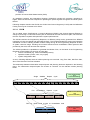
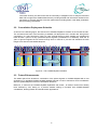
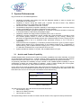
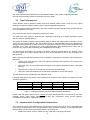
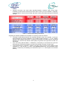
Italian Space Agency COSMO-SkyMed Mission COSMO-SkyMed System Description & User Guide 1 TABLE of CONTENTS 1 Scope of the Document....................................................................................................................... 3 2 COSMO-SkyMed Overview ................................................................................................................ 4 2.1 THE MISSION ................................................................................................................................. 4 2.1.1 The Satellite.......................................................................................................................... 7 2.1.2 The Payloads........................................................................................................................ 8 2.1.2.1 SAR instrument functions and acquisition mode characteristics .................................. 8 2.1.3 The Ground Segment ......................................................................................................... 10 2.1.3.1 CPCM .......................................................................................................................... 11 2.1.3.2 C-UGS ......................................................................................................................... 13 2.1.3.3 System Calibration ...................................................................................................... 13 2.2 CONSTELLATION DEPLOYMENT SCHEDULE .................................................................................... 14 2.3 FUTURE ENHANCEMENTS ............................................................................................................. 14 3 System Performances....................................................................................................................... 15 3.1 3.2 3.3 4 ARCHIVE AND PRODUCT CAPABILITY ............................................................................................. 15 TIME PERFORMANCES .................................................................................................................. 16 INTERFEROMETRIC CONFIGURATION PERFORMANCES .................................................................... 16 User Guide ........................................................................................................................................ 18 4.1 CATALOGUE BROWSING ............................................................................................................... 19 4.2 NEW ACQUISITIONS ...................................................................................................................... 21 4.2.1 Customer service request preparation and submission ..................................................... 21 4.2.2 Imagery request elaboration, feasibility analysis and depositing ....................................... 22 4.3 DELIVERY .................................................................................................................................... 22 4.4 WEB GUI.................................................................................................................................... 23 5 Acronyms and Glossary .................................................................................................................... 37 5.1 5.2 ACRONYMS .................................................................................................................................. 37 GLOSSARY ................................................................................................................................... 40 2 1 Scope of the Document Scope of the Document is to provide COSMO-SkyMed System AO Users with a System Description document giving a description of theSystem and its performances and to give a brief user guide for the service usage. 3 2 COSMO-SkyMed Overview COSMO-SkyMed (COnstellation of small Satellites for Mediterranean basin Observation) is the largest Italian investment in Space Systems for Earth Observation, commissioned and funded by Italian Space Agency (ASI) and Italian Ministry of Defense (MoD), and it is “natively” conceived as a Dual-Use (Civilian and Defence) end-to-end Earth Observation System aimed to establish a global service supplying provision of data, products and services compliant with well-established international standards and relevant to a wide range of applications, such as Risk Management, Scientific and Commercial Applications and Defence/Intelligence Applications. The system consists of a constellation of four Low Earth Orbit mid-sized satellites, each equipped with a multi-mode high-resolution Synthetic Aperture Radar (SAR) operating at X-band and fitted with particularly flexible and innovative data acquisition and transmission equipment. The system is completed by dedicated full featured Ground infrastructures for managing the constellation and granting ad-hoc services for collection, archiving and distribution of acquired remote sensing data. COSMO-SkyMed Mission offers today an efficient response to actual needs of Earth Observation Market providing an asset characterized by full global coverage, all weather, day/night acquisition capability, higher resolution, higher accuracy (geo-location, radiometry, etc.), superior image quality, fast revisit/response time, interferometric/polarimetric capabilities and quicker-and-easier ordering and delivery of data, products and services. The system is conceived to pursue a Multi-mission approach thanks to its intrinsic Inter-operability with other EO missions and Expandability towards other possible partners with different sensors typologies to implement an integrated space-based system providing Earth Observation integrated services to large User Communities and Partner Countries (IEM capability). These features designate COSMO-SkyMed as a system capable to provide “Institutional Awareness” in order to make proper decisions in preventing and managing world-wide crisis. In a Dual-Use environment, particular emphasis has to be put on Dual-Use Mission Planning functionality in order to optimize system utilization and fulfilling at the same time different user classes needs: an insight into the peculiar characteristics of the COSMO-SkyMed Dual-Use Mission Planning and the technical methodology approach to the sharing of System Resources in a Multi-User setting is provided. Following chapters give a quick overview about the COSMO-SkyMed mission objectives and design. 2.1 The Mission The mission objectives of COSMO-SkyMed are related to a space mission having a dual nature (i.e. capable to satisfy civilian and defence customers) able to provide information and services to a number of activities and applications, such as Risk Management Applications, Cartography and planning applications, agriculture, forest, hydrology, Geology, Marine domain, Archaeology etc. The set of requirements imposed at highest level has brought to the following needed performances: • Large amount of daily acquired images, • Satellites worldwide accessibility, • All weather and Day/Night acquisition capabilities, • Very fast interval between the finalization of the user request for the acquisition of a certain geographic area and the release of the remote sensing product (System Response Time) • Very fine image quality (e.g. spatial and radiometric resolution) • Possibility of image spatial resolution trade-off with size, at most possible extent and including sub-meter resolution; • Capability to be a cooperating, interoperable, expandable to other EO missions, multimissionborne element providing EO integrated services to large User Communities on a worldwide scale 4 Due to the need of many combinations between image size and spatial resolution the SAR was chosen as a multimode sensor operating in: • • • A Spotlight mode, for metric resolutions over small images Two Stripmap modes, for metric resolutions over tenth of km images; one mode is polarimetric with images acquired in two polarizations Two ScanSAR for medium to coarse (100 m) resolution over large swath FLIGHT DIRECTION SWATH HUGEREGION WIDEREGION HIMAGE POLARIMETRIC SCANSAR SPOTLIGHT STRIPMAP Figure 1 – The 3 acquisition modes of COSMO-SkyMed sensor The constellation consists of 4 medium-size satellites, each one equipped with a microwave highresolution synthetic aperture radar (SAR) operating in X-band, having ~600 km access ground area. The orbit characteristics are summarized in the following table. Orbit Type SSO Inclination 97.86° Revolutions/day 14.8125 Orbit Cycle 16 days Eccentricity 0.00118 Argument of Perigee 90° Semi Major Axis 7003.52 km Nominal Height 619.6 mk LTAN 6:00 A.M. Number of Satellites 4 Phasing 90° Deployment Progressive 5 Table 1 Orbit characteristics In nominal conditions, the four satellites are equi-phased in the same orbital plane as depicted in the following figure: Z ECI SAT #4 Orbital plane Equatorial plane To Sun Y ECI SAT #1 SAT #3 Line of Nodes X ECI SAT #2 Apses Line Figure 2 - COSMO constellation nominal configuration The nominal (full sized) constellation orbiting configuration is conceived to achieve the best compromise among cost and performance, providing a global Earth access at constellation level of few hours, with at least two opportunities in one day to access the same target site on the Earth under different observing conditions (incidence angle). The interferometric constellation orbiting configuration instead, is aimed to produce three-dimensional SAR images by combining two radar measurements of the same point on the ground in interferometric conditions. One interferometric configurations is supported: • Tandem, in which the two satellites fly in close proximity achieving the interferometric acquisitions in near real time The following figure shows the Tandem interferometric configuration, with the two satellites working together placed in different orbit planes and with 20" of separation corresponding to an along-track separation of 151 Km, and a plane separation of 0.08 deg. 6 ZECI Leader Follower Nominal frozen orbit YECI XECI ΔΩ AN AN Figure 3 - Interferometry tandem configuration with different orbit planes 2.1.1 The Satellite The COSMO-SkyMed satellite pictorial representation (shown in deployed configuration) is given in the following figure Figure 4 - SAR Satellite (Deployed and Stowed Configurations) Its architecture consists of the subsystems and payloads briefly summarized below: • Integrated Control Subsystem (ICS), which is the controlling system on board the spacecraft for the collection and distribution of information (commands, telemetry, on board data, and timing) and for the supervision of COSMO-SkyMed Bus and Payload subsystems • Telecommands Protection System (TPS) which provides on-board decryption of the Telecommands received from ground • Telemetry Tracking & Command (TT&C), which provides the two-ways S-band communication links between the satellite and the TT&C Ground Station • Electric Power Subsystem (EPS) which is composed of Solar Array wings, the drive motors to orientate the Solar Array wings, a Power Control Unit, the battery cells, the Current Unit Sensor and the SAR Antenna power supply • Propulsion Subsystem (PRP) which includes six thrusters, arranged in two independently operable branches of three thrusters each, and the propellant and the pressurant, which are stored in a common tank • Thermal Control Subsystem (THC) which consists of physical elements that insulate the 7 • • external surfaces of the satellite, heat pipes and thermal doublers to spread the heat load to be dissipated, radiator panels, and automatic electrical heaters placed under ICS control SAR Instrument payload, an X-band radar operating in multi-resolution, multi-polarizations on a wide area access region, equipped with a fixed antenna with electronic scanning capabilities and implements many measurement operative modes for acquiring images and performing the internal calibration Payload Data Handling and Transmission (PDHT), managing all the Data handling and Transmission of the Science Data generated by the SAR payloads on-board COSMO-SkyMed satellites. It includes all the necessary interfaces for acquiring telecommands and ancillary data from ICS and for storage, formatting, encryption and ground downlink of the science data from the SAR instrument 2.1.2 The Payloads The COSMO satellite main payloads are a Synthetic Aperture Radar (SAR) instrument and a Payload Data Handing and Transmission (PDHT), commanded via Time-Tagged Telecommands contained in a Command Plan. 2.1.2.1 SAR instrument functions and acquisition mode characteristics The functions foreseen for the SAR payload are: • SAR Macrocommand Execution Control, which receives from the Satellite On-board Management function all time-tagged macrocommands (covering a given time period, e.g. 24 hours) and activates them at the foreseen time, allowing to: ¾ implement SAR Measurement Mode Setting according to the MCMD parameters ¾ activate the SAR instrument throughout all its intermediate state up to the ‘operational state’ in which the image acquisition is performed in the foreseen measurement mode ¾ form the SAR beam for transmitting and receiving the radar signals, in different measurement modes • SAR Instrument Control, which on receipt of the macrocommands set-up the SAR instrument mode according to macrocommands parameter values, specified for a given image acquisition. The sensor imaging operating modes are: ¾ Spotlight Mode, in which the antenna is steered (both in the azimuth and the elevation plane) during the overall acquisition time in order to illuminate the required scene for a time period longer than the one of the standard strip side view, increasing the length of the synthetic antenna and therefore the azimuth resolution (at expense of the azimuth coverage). In such configuration the acquisition is performed in frame mode, hence it is limited in the azimuth direction due to the technical constraints deriving from the azimuth antenna pointing. The implementation allowed for this acquisition mode is the Enhanced Spotlight. In the Enhanced Spotlight mode, the spot extension is achieved by a antenna electronic steering scheme requiring the centre of the beam steering to be located beyond the centre of the imaged spot, thus increasing the observed Doppler bandwidth for each target. Such mode is characterized by an azimuth frame extension of about 11 Km, a range swath extension about 11 Km, PRF values ranging from a minimum of 3148.1 Hz to a maximum of 4116.7 Hz, allowed chirp duration in the range [70, 80] microseconds (depending on specific access area), a chirp bandwidth (accommodated along range on the basis of the required ground resolution) ranging from 185.2 MHz to 400.0 MHz and finally (due to the de-ramping processing) a sampling frequency equal to 187.5 MHz (same for each acquisition configuration) ¾ Stripmap Mode, which is the most common imaging mode (e.g. similar to ERS mission one), obtained by pointing the antenna along a fixed direction with respect to the flight platform path. The antenna footprint covers a strip on the illuminated surfaces as the platform moves and the system operates. The acquisition is virtually unlimited in the azimuth direction, except for the limitations deriving from the SAR instrument duty cycle (about 600 s, allowing a strip length of 4500+ km). Two different implementation of this mode are foreseen: the Himage and the PingPong. In the Himage mode, the radar 8 Tx/Rx configurations are time invariant, allowing receiving from each ground scatterer the full Doppler bandwidth allowed by the azimuth aperture of the antenna beamwidth. The Himage is characterized by a swath width of about 40 km, an azimuth extension for the standard product (square frame) about 40 Km (corresponding to an acquisition of about 6.5 sec), PRF values ranging from a minimum of 2905.9 Hz to a maximum of 3874.5 Hz, a chirp duration in the range [35, 40] microseconds, a chirp bandwidth accommodated along range on the basis of the required ground resolution, spanning from 65,64 MHz at the far range (with a sampling rate of 82.50 MHz) to 138,60 MHz at the far range (with a sampling rate of 176.25 MHz). The PingPong mode implements a strip acquisition by alternating a pair of Tx/Rx polarization across bursts (crosspolarization) obtained by mean of the antenna (which may be adjusted to be different on transmit and on receive). The acquisition is hence performed in strip mode alternating the signal polarization between two of possible ones i.e. VV, HH, HV and VH. In this polarimetric burst mode only a part of the synthetic antenna length is available in azimuth and consequently the azimuth resolution is reduced. This mode is characterized by a swath width value of about 30 km, an azimuth extension for the standard product is about 30 Km (square frame) corresponding to an acquisition of about 5.0 sec, PRF values ranging from a minimum of 2905.9 Hz to a maximum of 3632.4 Hz, a chirp duration fixed at 30 microseconds, a chirp bandwidth accommodated along range on the basis of the required ground resolution, spanning from 14.77 MHz at the far range (with a sampling rate of 18.75 MHz) to 38.37 MHz at the far range (with a sampling rate of 48.75 MHz) ¾ • • ScanSAR Mode, which allows larger swath in range with respect to the Stripmap one, but with a less spatial resolution, obtained by periodically stepping the antenna beam to neighbouring sub-swaths. Since only a part of the synthetic antenna length is available in azimuth, the azimuth resolution is hence reduced. In such configuration the acquisition is performed in adjacent strip mode, hence it is virtually unlimited in the azimuth direction, but for the limitations deriving from the SAR instrument duty cycle that is of about 600 s. The two different implementation are allowed for this acquisition mode are WideRegion and HugeRegion. In the WideRegion mode the grouping of acquisition over three adjacent subswaths allows achieving ground coverage of about 100 Km in the range direction. The azimuth extension for the standard product is about 100 Km (hence envisaged for the origination of a square frame) corresponding to an acquisition of about 15.0 sec. This mode is characterized by PRF values ranging from a minimum of 2905.9 Hz to a maximum of 3632.4 Hz, a chirp duration in range [30, 40] microseconds, a chirp bandwidth accommodated along range on the basis of the required ground resolution and spanning from 32.74 MHz at the far range (with a sampling rate of 41.25 MHz) to 86.34 MHz at the far range (with a sampling rate of 108.75 MHz). In the HugeRegion mode the grouping acquisition over up to six adjacent subswaths allows achieving ground coverage of about 200 Km in the range direction. The azimuth extension for the standard product is about 200 Km (hence envisaged for the origination of a square frame) corresponding to an acquisition of about 30.0 sec. This mode is characterized by PRF values ranges from a minimum of 2905.9 Hz to a maximum of 3632.4 Hz, a chirp duration in the range [30 40] microseconds, a chirp bandwidth accommodated along range on the basis of the required ground resolution and spanning from 8.86 MHz at the far range (with a sampling rate of 11.25 MHz) to 23.74 MHz at the far range (with a sampling rate of 30.0 MHz) Instrument State Transition Control dedicated to manage the SAR instrument operations in the allowed operative states (ordered from the lower level to the higher level of operability: LEO, OFF, RESET, INIT, HEATER, PRE-OP, SILENT, OPERATIONAL, REFUSE). All SAR state transitions (except power-on and autonomous recovery transition) are commanded from ground through uploaded telecommands (i.e. part of the Command Plan) Beam Forming, which sets-up the SAR instrument for transmitting and receiving the radar signals, and achieving the requested SAR measurement mode: ¾ In SPOTLIGHT modes, the SAR instrument is operated mainly through the antenna azimuth beam steering. ¾ In STRIPMAP modes, the SAR instrument is operated mainly with a fixed antenna beam in either single or multiple polarization 9 In SCANSAR modes, the SAR instrument is operated mainly through the antenna elevation beam steering. Signal Generation, which makes usage of linearly frequency modulated RF pulses (having a duration ranging from 10 to 80 μs depending on the operational mode and mode parameters) and bandwidths between 0 (sinusoidal tones) and 400 MHz. The signal generation function includes: ¾ Baseband generation, where the waveform synthesis makes use of a generation scheme in which the pulse is built in the time domain by means of a sampled technique. Each pulse sample is computed on the basis of a mathematical model where both theoretical behavior and hardware induced distortions are reflected. The sampling frequency is 180 MHz, which is three times the maximum absolute spectral component (mono lateral) of desired waveform. In such a way a 1.5 over-sampling factor is always guaranteed. Although the SAR uses signals with programmable bandwidths, a fixed sampling frequency concept, guaranteeing the best phase and time jitter performance, has been selected ¾ IF synthesis, where the two base band chains are combined into one single channel after the single side band modulation. This function performs at the same time both the frequency translation at IF centre frequency, set at 1275 MHz, and the side band suppression that permits the passage from the vector signal representation (complex mathematics) to the true pulse waveform ¾ IF up-conversion which is based on a bandwidth (and centre frequency) multiplication concept and a L.O. value at 1125 MHz ¾ Bandwidth multiplication by x4, chosen as the best way in order to avoid critical power supply budget (digital level), technological boundaries and timing problems and is done with a totally analogue technique (allowing very good phase performance over the pulse) ¾ X-band Driver with Amplitude Modulator in which to prevent coupling issues to the active antenna (whose gain is subject to possible adjustments and optimizations) a RF adaptive power level function is executed as a time domain sampled stepped attenuation. The amplitude modulation samples are set to adjust the medium power Xband amplifier output. Due to the antenna characterization a slow varying dependence on frequency in 9600+/-200 MHz range can be expected so that a non-uniform envelope sample sequence could be envisaged Image Acquisition (T/R), performed by the SAR antenna which transmits the radar signals and receives the returned radar echoes during the OPERATIONAL state Echo Signal Elaboration, dedicated to the signal processing performed on the returning radar echoes, in terms of sampling, digitalization, data formatting as standard science data packets, and forwarding to the PHDT. The function is decomposed in the following elementary functions: ¾ electromagnetic beam coupling, that allows power transfer from each wavefront element incident on its patched array ¾ elementary signal power very low noise amplification; ¾ angular discrimination via RX beam forming, practically a phase delay on each signal contribution; ¾ combination of all signal elements into the equivalent “sensitive beam”; ¾ interface to in-board electronics. ¾ • • • 2.1.3 The Ground Segment The Ground Segment is responsible for the operations and control of the entire system including the generation and dissemination of the final products. It is composed of: • the Core ground Segment, including Satellite control facility, TT&C, Internal Communication Network, Flight Dynamics System • Mission planning and control centre, including Mission planning facility (CPCM) • Receiving, processing and archiving centres, including Processing and archiving facility, Satellite data receiving stations, Data exploitation, Calibration & validation, Data distribution • Communication infrastructure including Terrestrial links • Remote Ground Stations, including External TT&C Network, Satellite data receiving stations • Mobile Acquisition and Processing Stations • Fiducial Network, which provides GPS ephemeris and correction data necessary to improve 10 precision in Precise Orbit Determination (POD) An Integrated Logistics and Operations Segment (ILS&OPS) includes all necessary operations & logistic resources and services required for operating the space segment throughout the whole system lifetime Following chapters describe the CPCM, the Civilian User Ground Segment (C-UGS) and the Calibration Facility, that may be of interest to AO Users. 2.1.3.1 CPCM The so called Centro Pianificazione e Controllo Missione (CPCM) is the Ground Segment Element in charge of producing a conflict-free mission plan of activities for the near future time span, which achieve the user acquisition requests and optimise the system performances. The CPCM receives the Programming Requests, at different priority levels, generated from different typologies of users at national and international levels. The CPCM evaluates the system and operative constraints in order to identify possible conflicts arising among all the Programming Requests in terms of system resource usage, including the on-board resources and constellation orbital dynamics data provided by the CGS, then archives the requests. The CPCM provides the capabilities to generate the Mission Plan, on the basis of the Programming Requests received taking into account as input data: • mission constraints (e.g. resource availability status), • operative modes (routine, crisis, very urgent) • system configuration data. As such, following different levels of mission planning are conceived: Long Term Plan, Mid-Term Plan, Short Term Plan and The Fine Schedule The relationship between observation temporal spans and planning levels are depicted in the following figure. The observation temporal spans are chosen as ‘horizons’ for the relevant mission planning levels. Single 1 2 3 4 5 6 Full Satellite 7 8 Constellation Repeat 9 Long Term Planing and Coarse Scheduling Cycle 10 11 12 13 14 15 16 Repeat Cycle Medium Term Planing and Coarse Scheduling 1 2 3 4 Time for global Earth access at constellation level 0 - 12 11 Short Term Planing and Fine Scheduling Fig. 1 Figure 5 - COSMO-SkyMed Observation temporal spans and mission planning levels The Long Term Plan (LTP) and its associated coarse schedule cover a mission time period multiple of the 16 days repeat cycle of a single satellite. This time span covers either long term missions such as regional monitoring, or routine (low priority) Programming Requests, taking into account major constellation orbital manoeuvres (e.g. for constellation re-phasing, stationkeeping, interferometry reconfiguration). The LTP coarse schedule is the gross allocation of planned activities on the relevant long-term temporal scale. It is conceived by leaving some temporal leeway in the planned activities being based upon long-term predicted orbit, predicted system resources availability and temporal events. The Mid-Term Plan (MTP) covers a time span designated as the repeat cycle of the spacecraft constellation. This time period depends on the number of active satellites of the constellation, and specifically: • four days with a 4-satellites constellation • eight days with a 2-satellites constellation • sixteen days with 1- or 3-satellites constellation The MTP is associated to a coarse schedule, which roughly allocates the planned activities onto the mid-term temporal scale. Fine timing of activities and events are not yet resolved, still leaving some temporal leeway in planned activities, which are based upon predictions on the mid-term period, in terms of orbits, resources availability, and events. The COSMO mission planning process is focused on mid-term period, which constitutes the fundamental planning stage. Indeed the mid-term time period is the planning horizon which refers to the observation repeat cycle of the whole constellation. As such, this time period contains all possible imaging observation geometries that are physically achievable by COSMO constellation. The MTP is the first stage of the planning process that receives as input all Programming Requests. As a matter of fact, all PRs are being first planned at mid-term level. However it does not mean that every PR will necessarily be served within the mid-term span (e.g. four days). Indeed this time period can be shorter, depending on imposed planning constraints. The MTP planning process applies rules to manage request’s priorities. For example, in considering data downloading, the following rules are applied: • SAR data files coming from High Priority programming requests are downloaded in priority to the relevant reception station • SAR data files coming from routine requests are downloaded to the relevant receiving station(s), with a hierarchy driven by the last desirable date for the requested data and weighted by the location along the sub-satellite line of the considered receiving stations Finally, it should be pointed out that the planning process allows the highest priority for satellitereserved service activities in connection with: • station keeping task implementation • urgent maintenance /technological operations (e.g. failure management, OBSW patching, calibrations) Short Term (ST) Planning and fine scheduling has the objective of generating the Mission Plan that covers the incoming 24 hours of operations. The plan is extracted from the Mid-Term Plan, and contains the planned activities therein foreseen for the relevant short term time span. The associated STP Fine Schedule is obtained by refining and detailing the fine placement of those planned activities onto the temporal scale, taking into account: • Lastly updated very precise constellation orbit predictions. • Activities dependencies • Current system resources availability status • Actual operation progress status Finally, the Fine Schedule elaborates the detailed timeline associated to the short-term plan, taking into account the precise orbital predictions computed on the most recent precise orbit determination data 12 The Mission Plan is the final output of the programming functional chain. It shall contain at least the following information: (i) time interval the Mission Plan is referred to; (ii) list of macrocommands to be converted in command procedures by CCS (such as switch on/off the SAR beam, start/stop tape, downlink session start/stop, etc.); (iii) admissible time interval for the task execution completion. In nominal condition (routine mode) the time interval of the mission plan is limited to 24 hours. 2.1.3.2 C-UGS The C-UGS (Civil User Ground Segment) is the Ground Segment Element in charge to handle, overall, the Payload Data acquires from SAR sensors, according to User Request. The main functions are: • Interfacing the users to offer access to COSMO SkyMed products and service (catalogue consultation, requests of products processing from data, processing of new data acquisitions, etc) • Split User Requests in their main components and handle the relevant workflow (Acquisition, Processing and Distribution) • Provides requests feasibility analysis, ranking of priorities and priority harmonization among partners; • Receive payload data from satellite X-band downlink; • Receive and process support data necessary for data processing and image geo-location (e.g. from GPS ground fiducial network); • Perform Production Management in terms of: o Generation of SAR image products, o Cataloguing and archiving of products and raw data • Distribute products to users • Ensure Interoperability with other Partner UGS in order to export / import products, submitting and accepting requests; • Provide Mobile Acquisition and Processing Stations (MAPS Station). 2.1.3.3 System Calibration The System Calibration functions are conceived to support the in-flight performance verification, in-flight characterization and calibration of the SAR instrument (during system commissioning, as well as throughout the lifetime of the system, either periodically or to cover specific needs or events). The Calibration Functions are performed both on-board the satellites and on-ground, the latter by means of: • SAR Engineering Calibration Facilities (SECF) • External calibrators • Calibration sites The focal point of the System Calibration Functions are the SAR Engineering Calibration Facility and the Satellite Manufacturer, which goal is to undertake the activities of Instrument characterisation, calibration, and verification with respect to: • image quality • instrument pointing • data geolocation In order to achieve these goals, the SECF functions are actually strictly coordinated with the Exploitation Functions. The SAR Engineering Calibration Facility (SECF) (as well as the Satellite Manufacturer) is involved in the calibration operations. The first has the role to manage all the calibration operations and to monitor the image quality while the latter to implement the corrective actions eventually implied by SECF monitoring results affecting the Satellite, Payload or On ground configurations. The main outputs of SECF consists in: • generation of the calibration data which is then distributed to all GS • regular activity reports which summarise the on-board instrument performance. In case of 13 instrument anomaly, the SECF will have the necessary investigation tools to analyse instrument data and to support the Satellite Manufacturer providing all data and information needed for the generation of the SAR Payload correction parameters (including beam mode table parameters and processing parameters) 2.2 Constellation Deployment Schedule As shown in the following figure, the first launch of COSMO-SkyMed is foreseen in the first half of 2007. The successive launches of the remaining 3 satellites, will take place at a 8 months rate, being hence completed in a 2 years time frame. With a 5 years nominal lifetime of each satellite, this schedule will leave at least 3 years of a fully operational space segment (constellation of 4 satellites), while the 15 years of ground segment life will ensure enough time to continue to process and distribute the SAR images even after the last satellite disposal. Processing and Dissemination of Products 4 satellites in operations Figure 6 – The COSMO-SkyMed schedule 2.3 Future Enhancements The Italian Space Plan foresees a continuation of the space segment of COSMO-SkyMed with a next generation of 4 upgraded COSMO-SkyMed satellites planned in order to maintain a whole constellation after the gradual disposal of the first constellation elements; Moreover, to enhance the COSMO-SkyMed capabilities and results, an add-on mission has already been selected by ASI, basing on a passive satellite orbiting in formation with COSMO-SkyMed constellation, allowing bistatic and interferometric applications. 14 3 System Performances Key performances of COSMO-SkyMed are: • • • • • • • • • 3.1 Worldwide accessible area starting from the first deployed satellite, in order to acquire and furnish data on the entire earth Capability to acquire, during the orbital cycle, a specific site with at least 2 very different incidence angles, on the same side of the orbital plan Revisit time of the constellation lower than 12 hours Constellation average daily acquisition capability of 1800 images acquired in a 24 hours moving window (75 Spotlight plus 375 Strip or ScanSAR for each satellite) Constellation peak daily acquisition capability of 10 minutes of continuous operation in Stripmap or ScanSAR modes or alternatively 20 spotlight images Capability to deliver the image product required by the PI user in 72 hours Capability to acquire interferometric image couples with a time separation of one day or even few minutes (tandem mission in which two SAR satellites fly very closely), allowing the generation of Digital Elevation Model products with a absolute height accuracy ranging from 8m in Spotlight mode to 58 m in ScanSAR mode (horizontal accuracy of 18 m and 52 m, respectively) SAR Products suite composed by 5 “standard” products levels and 7 types of product “higher” product levels obtained by a postprocessing of the standard products (e.g. coregistration or speckle filtering), with a spatial resolution ranging from 1 m up to 100 m, a radiometric accuracy of 1 dB and a localization error on ground with as low as 15 m System Operational Lifetime of 15 years, with a satellite lifetime of 5 year. Archive and Product Capability COSMO-SkyMed Data Archives and Products processing capabilities have been basically conceived and architecturally implemented as “modular” features, able to satisfy both actual Dual Use foreseen needs and future ones, thanks to the concept of Scalability embedded in the system architecture. As previously described the Scalability concept is based on the COSMO-SkyMed capability to vary its configuration to satisfy new needs, adding (or deleting) ‘copies’ of blocks already part of the system, and configuring it properly (e.g. adding other archiving or processing units). On the basis of the actual envisaged Users daily needs and the relevant daily volume of payload data sensed by the entire constellation and down-linked to ground, the following raw daily data volume has been taken into account concerning the actual data archives dimensioning: IMAGE TYPE CUGS NARROW FIELD 175 WIDE FIELD 300 TOTAL DATA VOLUME / UGS 475 Table 2 – Data Volume The data archives have been structured in three hierarchical levels: • On-line data (7 days) • Near-on-line data (6 months) • Off-line data (15 years) The System daily products number at C-UGS is 200 for levels 1C/1D, higher for lower product levels. 15 Any future needs shall be satisfied by the embedded scalbility of the system, upgrading both data archives and processing chains as required by the User needs. 3.2 Time Performances Three different System operative modes have been defined (called routine, crisis and very urgent) allowing to respond to different needs in term of required programming latency. In the first mode (routine) the requests of the users pertaining image acquisitions are planned and sent to the constellation once a day. In the second mode (crisis) this operation is done twice a day. The third mode (very urgent) is asynchronous, allowing the servicing of an image acquisition request with the minimum possible latency. The system is capable to satisfy a User Request (ability to deliver the image product required by an End User in a timely manner) which in the case of the first level of SAR standard products (not derived from spotlight mode acquisitions) is within 72 hours for the system working in routine mode (acquisition plan uploaded once a day), 36 hours for the crisis mode (acquisition plan uploaded twice a day) and 18 hours for very urgent mode (acquisition plan uploaded asynchronously). The Government Authorities are in charge to require a change of System Modes (i.e. Routine, Crisis, and Very Urgent) or to require specific services, such as the imposition of veto on the acquisition over specific areas. More in general, the time performances of the constellation are defined on the basis of the following four definitions: reaction time: time span from the User request acceptance and Deposit at the C-UGS to the SAR image acquisition; information age: from the SAR image acquisition to the product availability at the C-UGS (data latency); response time: is the sum of the reaction time and the information age; revisit time: time span between two consecutive acquisitions over the same target. The delivery time is not considered in the Response Time. Following table reports the values to be considered for the above times (values are referred to routine operative conditions): Information age Response Time Revisit time 1 satellite 12 h 110 h 65 h 2 satellites 12 h 90 h 40 h 3 satellites 12 h 85 h 40 h Full constellation 12 h 72 h 12 h Table 3 – Timing performances of the COSMO-SkyMed constellation Please note that these values refer to routine (nominal) operational status, and that they are mean foreseen values, while actual values depend upon site coordinates, active ground segment, constellation configuration, operational mode etc. 3.3 Interferometric Configuration Performances The main performance of the interferometric configuration from the user point of view, is associated with the accuracy of the products which are generated in such acquisition modality i.e. the Digital Elevation Model (DEM). The accuracies of the DEM (shown in next table) are: • Relative accuracies: errors in absence of any calibration, true height not known 16 • Absolute accuracies: true errors within specified Baseline, Incidence angle, terrain slope, availability of 2500 Ground Control Points with 100m accuracy for each subswath in Stripmap, Scansar modes or Ground Control Points with 30m accuracy and 300m spacing for Enhanced Spotlight Table 4 – Interferometric DEM performances Regarding the attitude capabilities of the satellite, four pointing modes are allowed: • The Right Looking Nominal Mode is the standard operation mode of the satellite, in which the SAR instrument has access capability in the incidence angle range 25° ≤ * ≤ 50°, yielding optimum radar imaging performance. It requires the pointing of the SAR antenna mechanical boresight (i.e. normal to the antenna surface plane) on-ground to the right side at 34.065° offnadir angle • The ‘Left Looking Nominal Mode’, is obtained by commanding a roll manoeuvre to point the SAR antenna mechanical boresight on-ground to the left side at 34.065° off-nadir angle • The Extended Mode is obtained by platform roll agility, gaining access to the incidence angle ranges 20° ≤ * ≤ 25° and 50° ≤ * ≤ 59.5°, with degraded performance. This ‘Extended Access Region’ is achieved by commanding a roll manoeuvre up to -7/+ 7° with respect to the nominal pointing. 17 4 User Guide COSMO-SkyMed has built-in functions which allows the following operations (using Internet with the support of a Graphic User Interface or GUI): • Permit to unregistered users a simplified consulting of available services • Perform user registration and user profile creation • Authenticate and restrict the user access to the system on the basis of its own profile • Allow browsing capability to retrieve help and info on the available services • Manage, by means of "easy to use" graphic front-end, all customer service request • Aid the service request composition with tailored data entry forms able to avoid bad parameters introduction • Allow the customer to monitor the status of its service requests • Manage the final product delivering to customer Registered customers access the C-UGS functionalities via Internet. The session authentication is implemented by a standard username/password mechanism. Users may perform their registration request, filling up a form via Internet. The registration request submitted by the candidate customer is then processed by authorized personnel. A successful user registration request allows the releasing of both the user authorization and the associate user profile. An e-mail notification is however sent back to the candidate user, in order to inform him about the success or rejection of his registration request. The user profile, stored in the COSMO-SkyMed User Data Base and editable by the user itself, contains the following information: • authentication information (e.g. for logging into the system) • personal/company information (e.g. for product shipment) • customer class • access rights and restrictions (i.e. services that the user is authorised to access) • credit information (e.g. authorized means of payment, available credit. For AO users products are free) • link to personal data storage area (allowing the electronic delivery of image products) • preferences • default notification mechanism (e-mail, SMS, Fax) • special conditions There are three ways to fulfill a Civilian Customer Request for a image product: • The system catalogue contains a raw satellite image fulfilling user’s constraints (e.g. geographical and temporal coverage, quality level). In this case, the customer submits a Product Elaboration Request composed of one or several imagery products. Such elaboration then starts from input raw satellite images found into the satellite data archive • The system catalogue contains a product (a raw satellite image already processed) fulfilling user’s constraints. In this case, the Civilian Customer Request is only composed of a delivery request composed of one or several product copy requests from input products already found into the archive • In the system's archive does not exist a raw satellite image or product satisfying user’s constraints, therefore, one or more new acquisitions from satellite are needed Many types of Requests exist, in order to satisfy various needs. The AO users can apply for Routine Request only, handled by the Civilian User Ground Segment or C-UGS. If any conflict with high priority request comes out, the planning center downgrades the civilian request priority in favor of the high priority one. Some further ancillary services are allowable to the users apart from the main services for user access and product ordering (just shown before). These ancillary services are: • Guide, providing general information about the COSMO-SkyMed system, applications and offered services • Bulletin Board, providing information about major events impacting the operability of the system • Problem Solving, allowing the user to notify a problem / receive information about the solution • System documentation/information, realizing a controlled access to COSMO-SkyMed 18 documentation / information The user has always the opportunities to view and cancel (to a certain extent) his submitted requests. The service request follow up interface gives access to the list of all submitted user’s requests. For each request, it is possible to view the global status of the request and the detailed status of its elementary items (products). The request status is updated by the system each time a significant event takes place (analysis, planning, acquisition, processing, delays, etc.). The user can request the deletion of a whole service request or of part of it at any time, but the system will accept it only under certain conditions: • Delivery Requests can be cancelled at any time before the delivery process has been started. • Product Elaborations Requests can be cancelled at any time before the processing has been started. • Product Elaborations Requests on new acquisitions can be cancelled at any time before the acquisition has been planned by the CPCM. The service request follow up interface is also the entry point to retrieve the products for which the on-line delivery has been requested. 4.1 Catalogue Browsing Commercial Optical at C-UGS Interoperable Catalogues at C-UGS X X X X Institutional Civil Customers at C-MAPS National and International Commercial Customers X X National and International Commercial Customers at C-MAPS Commercial CSK-SAR at C-MAPS Commercial CSK SAR at C-UGS X Institutional CSK-SAR at C-MAPS Institutional Optical at C-UGS Institutional Civil Customers Institutional CSK SAR at C-UGS Catalogue are organised in collections. A collection is a set of homogeneous data identified by satellite/sensor or by product type. The available collections depend on the customer class and are shown in the following table, that reports the association between customer classes and available catalogues. X X X X Table 5 - Customer Classes vs. available Catalogues Catalogue browsing is a wide concept including guide, directory and inventory search. The Guide service offered by UGS provides information about collections characteristics including searchable attributes, resolution, key attribute, etc. The Directory service offered by UGS provides the list of the collections available on various UGS of the COSMO SkyMed Catalogue Interoperability Constellation. 19 Inventory search offers to users a query interface to retrieve items in the catalogue, which satisfy user’s specific interests. The interface is the same for all the catalogues accessible by the users, independently if they are local, remote or accessed through the interoperability protocol. The query parameters for a generic inventory search include at least: Search area The user interface supports different methods to define the geographical area: • Rectangle • Polygonal area • Circle (defined by center and radius) The Selection of the search area can be done by point-and-click, or point-and-drag, on a geographical map. As an alternative, the user has the possibility to manually input the vertex coordinates (lat,lon) defining the search area. The map visualization supports different map sets and visualisations options. The supported map datasets include at least: • Vectorial map showing political boundaries, rivers, cities, • Physical map • Political map The maps used by the graphical user interface must contain an adequate level of details to support the required zooming level, and may be different in the civilian and Defence context, as the Defence context must be capable to handle requests for classified products (higher map resolution required). Acquisition interval The time interval when the product has been acquired. This is a single interval defined by start date and stop date. Some predefined values shall be available for quick selection (today, yesterday, last week, last month, etc.). Satellite/Sensor Multiple selection from a predefined list of available couples. Depends on the catalogue sets available to the specific customer class. Product type Defines the level of processing and depends on the specific mission characteristics The User is allowed to choose the sorting criteria for results presentation. The search parameters can be saved, on user’s request, in the personal user area for further reuse. The results are organized in a list according to the presentation criteria selected by the user. For each item in the list the following information is accessible to the user: • geographic location (upper-left and lower-right corner coordinates; footprint over the map) • acquisition information (start stop time, orbit information, incidence angle, etc.) • product generation information; • Quality parameters • Thumbnail and quicklook 20 The user interface also gives the possibility to select the interesting items and to copy them to a separated personal basket. The basket contents can be saved, on user’s request, in the personal user’s area for later reuse. If the user has retrieved from the catalogue a set of products that satisfy his needs, he can submit a request for processing and or delivery of selected catalogue products. The selected products are moved to the user’s basket and made available to the service request function. The service request interface gives to the user the possibility to compose a complex request consisting of a combination of: 1. [0..n] Delivery Requests of existing catalogue products (only delivery is required); 2. [0..n] Product Elaboration Requests, to be processed (at the desired level and with the desired user parameters) from existing catalogue acquisitions (processing and delivery are required); 3. [0..n] Product Elaboration Requests to be processed (at the desired level and with desired user parameters) from a new satellite acquisition. In order to satisfy these requests, the UGS has to define a new Programming Request to be sent to CPCM. The identification of Delivery Requests (point 1. above) is done through the Product ID retrieved in the catalogue. The identification of Product Elaboration Requests (point 2. above) is done through the Product ID retrieved in the catalogue plus additional processing information, defined by the user for each product. The identification of Product Elaboration Requests on data to be acquired (point 3. above) consists of programming request information plus processing information provided by the user. 4.2 New Acquisitions Following chapters describe the steps the user shall expect during the request and the elaboration of new acquisitions. 4.2.1 Customer service request preparation and submission When requesting a new acquisition, the user must specify a set of data identifying his request, as follows. User Interest Area This is the area for which the user requests a new acquisition. The area is defined with the same methods available for the search area in the catalogue consultation. Optionally, the user can identify up to N Targets of Interest contained in the User Interest Area, identified by point coordinates (lat, lon). This information is directed to the operator that will perform the feasibility analysis of the request, in order to optimize the acquisition programming. Time constraints The user shall specifiy the time contraints for his request. Time contraints of the following types are supported: • Time interval (start date, stop date) • Periodic time interval (start date, stop date, repetition frequency, global period) Satellite/Sensor constraints The user shall specify the acceptable satellite/sensor configuration for the acquisition. User parameters include at least: • Orbit (ascending / descending) 21 • Satellite/sensor attitude (acceptable interval) Priority of the request. Finally, the user fills in the general parameters in the service request form that include at least: • Delivery information • Payment options (not applicable for AO users) A (partially) completed user service request can be saved, on user’s request, in the personal user’s area for later completion/reuse. When all the mandatory information has been provided, the user can submit his request to the C-UGS and the request is then registered with the status New. 4.2.2 Imagery request depositing elaboration, feasibility analysis and After users requests submission, the Image Customer’s Requests (ICR) data base (previously collecting all Customer’s imaging requests) is scrutinized for identifying those ones that require new image acquisitions from the satellites. After their identification, the ICR are checked for compatibility against the main system characteristics (e.g. geometric constraints, sensor features, etc.), so that each checked ICR can become one or more "Programming Requests" (PR). Then the PR feasibility analysis are started up in order to optimally define Programming Requests against system characteristics, planning constraints, resources allocation policy, and sharing quota. During this feasibility analysis functional stage, a set of information about a given Programming Request is processed. These information allow to assess the PR feasibility and to make decisions useful for mission planning purposes. An example is the possibility to define different Programming Requests associated to an unique Customer’s requests, in order to progressively achieve the full coverage of the requested geographic area. For a given PR, different imaging ‘Data Take Opportunities’ (DTO) are identified, and analysed in terms of compatibility with constellation geometry, orbits, revisit time, mission profiles, SAR instrument measurement mode, view angles, required power consumption, cost in terms of resource consumption, and compatibility against planning constraints (e.g. quota limits). The input Programming Requests are expressed either in terms of target zone or regions (defined either as a polygon or as a circle). At the end of the ICR processing, all Programming Requests checked as feasible are deposited. It should be noted that, even though all deposited PRs are feasible, they might not be yet mutually consistent. Each PR of the Routine List is associated with a value of “relative priority” with respect to other PRs of the list. Each selected Programming Request has been singularly passed through the feasibility analysis stage previously performed. The global costs associated to all PRs of the routine list are also computed. The use and consumption of the System Resources basically depend upon the following foreseen consumption parameters: • Thermal behaviour; • SAR TX Power; • Data Take Time Duration; • Data Volume; • Manoeuvres. At the end of this stage at C-UGS, the routine PR List is directly sent to CPCM for request planning. 4.3 Delivery The user can choose to get the requested products through an electronic delivery (FTP put/get) or through a media delivery. 22 4.4 WEB GUI Following some C-UGS screenshots from the website accessible to the PIs. Figure 7 - login 23 Figure 8 - News 24 Figure 9 - Services list and new acquisitions services 25 Figure 10 - Product ordering 26 Figure 11 - Selection of geographic area 27 Figure 12 - Selection of time window and acquisition type 28 Figure 13 - Selection of satellite and orbit 29 Figure 14 - Sensor mode choice 30 Figure 15 - Delivery type and mode choice 31 Figure 16 - Product format and tranfer type 32 Figure 17 - Final orders list 33 Figure 18 - Estimate of a new order (delivery estimated on statistical basis) Figure 19 - Catalogue order 34 Figure 20 - Mask for query from catalogue (here the temporal parameters are shown) 35 Figure 21 - List of available products 36 5 Acronyms and Glossary 5.1 Acronyms ACD product Archive, Cataloguing, and Distribution AAS-I Alcatel Alenia Space Italy AOCS Attitude and Orbit Control System ASI Italian Space Agency BOL Beginning Of Life CalVal Calibration and Validation CCS Centro Controllo Satellite CNES Centre National Etudes Spatiales COTS Commercial Off The Shelf CPCM Centro Pianificazione e Controllo Missione DEM Digital Elevation Model DOM Deposit Operator Manager DPA Data Performance Analysis DSHA Data Storage & Handling Assembly DTO Data Take Opportunity EO Earth Observation EPS Electric Power Subsystem FDS Flight Dynamic System GEC Geocoded Ellipsoid Corrected GFN GPS Fiducial Network GPS Global Positioning System GS Ground Station GTC Geocoded Terrain Corrected HDF Hierarchical Data Format HK House Keeping HW Hardware I/F Interface ICR Image Customer Request ICS Integrated Control System ICU Instrument Control Unit IGS International GPS Service LEOP Launch Early Orbit Phase LTAN Local Time Ascending Node LTDN Local Time Descending Node 37 LTP Long Term Planning M&C Monitoring and Control MAPS Mobile Acquisition and Processing Station MIB Mission Information Base MUR Italian Ministry of Research MLT Mission Time Line MMSU Mass Memory Storage Unit MTP Medium Term Planning NCC Network Control Centre P/L Payload PCU Power Control Unit PDHT Payload Data Handling and Transmission PDU Power Distribution Unit PLA PLAnning POD Precise Orbit Determination PR Programming Requests PRF Pulse Repetition Frequency PRI Precision Raw Image PRP Propulsion Subsystem RAAN Right Ascension of Ascending Node RF Radio Frequency RX Receiver S/C Spacecraft SAA SAR Antenna Assembly SAR Synthetic Aperture Radar SC Spacecraft SECF SAR Engineering Calibration Facility SIE SAR Integrated Electronics SSO Sun Synchronous Orbit STP Short Term Planning SW Software TC TeleCommand TCU Thermal Control Unit THC Thermal Control Subsystem TM/TC Telemetry / TeleCommand TT&C Tracking, Telemetry & Command TX Transmitter 38 UGS User Ground Segment UTC Universal Time Coordinates WAN Wide Area Network WGS World Geodetic System 39 5.2 Glossary Acquisition Mode One of the basic acquisition modes allowed by the SAR instrument • Spotlight (Enhanced Spotlight) • ScanSAR (WideRegion, HugeRegion) • Stripmap (Himage, PingPong) Acquisition Plan It is the plan of the acquisitions to be performed related to submitted programming requests, sent by the CPCM to the UGS. The Acquisition Plan specifies at least the following items. (i) the time interval of validity of the plan, (ii) the Inventory plan (see Definition), (iii) the Receiving Plan (see Definition) Acquisition Request The Acquisition Request is the elementary geographical unit that can be acquired unitarily by the SAR instrument. Considering the capabilities of the SAR instrument, it can be necessary to proceed with several acquisitions to achieve the full coverage of the whole geographical area specified by a Programming Request. The decomposition of the Programming Request into one or more Acquisition Requests is in charge of the feasibility analysis, which is performed according to user- and systemdependent constraints. Coarse Schedule It is a scheduling process performed by means of long/medium term predicted orbit, with the aim of leaving some leeway in the planned constellation activities and events onto the timeline. With respect to the CPCM programming framework, the Coarse Scheduling is associated to the elaboration of both the Long Term Plan and the Medium Term Plan. Constellation Operational Phases • Deployment - The constellation Deployment phase occurs every time a satellite is added to the constellation according the stepwise constellation deployment approach. In this constellation state the new satellite goes through the following phases: Mission Preparation, Launch, Early Orbit Phase and Commissioning. • Routine - The constellation routine phase occurs every time all the satellites, belonging to the constellation at that time, operates in single data take mode. • Interferometry - The constellation interferometry phase occurs every time a couple of satellites operate in interferometric mode. • Reconfiguration - The constellation reconfiguration phase occurs in the following cases: - Transitions for achieving an interferometric state, occurring every time the transition from/to an interferometric configuration is commanded. - Transitions for satellite disposal, occurring every time a given satellite is disposed and the other satellites of the constellation are consequently rephased 40 - Transitions for constellation renewal, occurring every time a constellation must be re-phased after a launch of a new satellite replacing the one previously disposed Data Screening Extraction of telemetry data from the Level 0 Data, containing geo-localization information, quality parameters and other useful information. Data Take Opportunity A set of feasible choices, made according to the Acquisition Request parameters, of satellite orbit, instrument mode, measurement modality, look angle and Image Acquisition Station(s) able to fulfill the Acquisition Request. DEM Digital Elevation Model. Terrain height data given on a regular map grid. DGM Product Synonymous with Level 1B Product Fast-Delivery Products Products where a reduced latency time is preferred and the precision and accuracy are maintained within the minimal requirements Fine Scheduling With respect to CPCM, the Fine Scheduling refers to the elaboration of activities and events into the relevant short term planning time span GEC Product Synonymous with Level 1C Product GTC Product Synonymous with Level 1D Product Image Customer Request (ICR) The ICR is generated by the Customer and forwarded to the relevant User GS Centre for being processed. It contains several information, including the petitioner identification, product type with geographical identification (target, strips, wide area) and geometrical configuration, type of acquisition (e.g. multi-temporal, interferometric), type of programmation (e.g. "standard" with a single acquisition, "periodic" with predefined time-intervals, "repetitive" on a geographic area during periods of predefined duration, and regularly time-spaced), designation of receiving stations, location for image products delivery, classification level, validity period, and priority level. Incidence angle It is the angle measured between the slant range direction and the normal to the tangent plane to the Earth surface in the specified point on ground Level 0 data L0 data (i.e. raw SAR telemetry) consists of time ordered echo data, obtained after decryption and before unpacking, and includes all UTC-dated auxiliary and ancillary data (e.g. orbit data, satellite’s 41 position and velocity, geometric sensor model, payload status, calibration data) required to produce the other basic and intermediate products. Level 0 Data File One Image Segment File (ISF) formatted as a sequence of Source Packets or VCDU’s Data Zones (decrypted or not depending on decryption key availability). The following standard processing levels are conceived for COSMO: Level 0 Product Level 0 product consists of time ordered echo data, obtained after decryption and decompression (i.e. conversion from BAQ encoded data to 8-bit uniformly quantised data) and after applying internal calibration and error compensation; this product shall include all the auxiliary data (e.g.: trajectography, accurately dated satellite’s co-ordinates and speed vector, geometric sensor model, payload status, calibration data,..) required to produce the other basic and intermediate products. Level 1A Product Level 1A products (also indicated as Single-look Complex Slant (SCS)), consist of SAR focused data internally radiometric calibrated, in zero-doppler slant range-azimuth geometric projection, left at natural geometric spacing with associated ancillary data Level 1B Product Level 1B products (also indicated as Detected Ground Multi-look (MDG)), consist of SAR focused data internally radiometric calibrated, de-speckled, amplitude detected, projected in zero-doppler ground range-azimuth onto a reference ellipsoid or on a DEM, resampled at a regular spacing on ground with associated ancillary data. Level 1C Product Level 1C class of products (also indicated as Geocoded Ellipsoid Corrected (GEC)) is constituted by input data projected onto a reference ellipsoid chosen among a predefined set, in a regular grid obtained from a cartographic reference system chosen among a predefined set with associated ancillary data Level 1D Products Level 1D class of products (also indicated as Geocoded Terrain Corrected (GTC)) is constituted by input data projected onto a reference elevation surface in a regular grid obtained from a cartographic reference system chosen among a predefined set with associated ancillary data Local incidence angle The angle between the radar beam center and the normal to the local topography. The difference between the global incidence angle and the terrain slope. Long Term Plan (LTP) The output of the planning and scheduling process provided by CPCM on a mission period multiple of the satellite repeat cycle. With respect to the planning process, the Long Term Plan covers the time span for planning long term Routine Programming Requests, such as regional monitoring and major constellation reconfigurations. With respect to the scheduling process, the Long Term Plan is associated to a coarse scheduling, based on long term predicted orbits and predicted system resources availability status. Look angle Of a SAR, the angle from the nadir at which the radar beam is pointed. Of a target, the angle between the SAR-nadir and SAR-target lines. 42 Mid Term Plan (MTP) The output of the planning and scheduling process provided by CPCM on a mission period of the constellation repeat cycle (i.e. 4 days). With respect to the planning process, the Medium Term Plan covers the time span for planning medium term Routine Programming Requests and High Priority Programming Requests. With respect to the scheduling process, the Medium Term Plan is associated to a coarse scheduling, based on medium term predicted orbits and predicted system resources availability status. Mission Plan Mission Plan is the final output of the programming functional chain. It shall contain at least the following information: (i) time interval the Mission Plan is referred to; (ii) list of macrocommands to be converted in command procedures by CCS (such as switch on/off the SAR beam, start/stop tape, downlink session start/stop, etc.); (iii) admissible time interval for the task execution completion. In nominal condition (routine mode) the time interval of the mission plan is limited to 24 hours. Nominal Scenario The nominal operational scenarios cover the different stages of system lifetime, in which the system configuration works "as expected" (according to specifications) and provides the requested performance levels. Non-Nominal Scenario The non-nominal operational scenarios cover the partial/total unavailability of the COSMO-SkyMed system elements. The non-nominal operational scenarios are deviations with respect to the nominal behaviour system. Pass Plan The Pass Plan, sent by the CPCM to the UGS, contains the flyby passages of the satellites over a given Fixed or Mobile (MAPS) Acquisition Station. Phase transitions Unidirectional sequence of operational stages through which the system lifetime evolves. For example: • COSMO-SkyMed system lifetime evolves through the following phases: "Pre-Operative", "Operative", "End Of Life" (EOL) (See: "System Operational Phases") • satellite lifetime evolves through the following phases: "Preparation", "LEOP", "Commissioning", "Routine", and "Disposal" (See: "Satellite Operational Phases") Planning Data The set of data which allows the CPCM to perform the planning and scheduling processes. Planning Data comprise both static (e.g. constellation geometry and orbital characteristics, resource availability profiles, quota computation reference data) and dynamic data (e.g. satellite ephemeris updates, operation progress data). Planning Process It is the process of finding a solution to acquire a submitted Acquisition Request, which is the goal of the planning process. The solution consists of a sequence of actions that must follow some defined rules (e.g. via pre-conditions and post-conditions of the actions), in order to assure the proper use of system 43 resources. The planning process is provided by using a relative time concept i.e. an action A precedes an action B without particular specification when the given action must be performed. Priority Level It is specified as the level of importance of the Programming Requests (i.e. either Routine or High Priority), in the mission plan elaboration process. Programming Request (PR) Subset of requests generated by the ICR (or User Request) decomposition concerning acquisition of image data not available in the archives. See Work Order definition. Raw Product Synonymous of Level 0 Product Resource Sharing The set of rules defined to balance satellites resources usage, in terms of programming requests, among COSMO-SkyMed users, according to established quota allocated to users. The resource sharing rules are driver to the selection of requests to be inserted into the mission plan . SAR Product Generic term referring to the SAR data acquired in the different SAR modes and handled in the GS, at different level of processing (see also Level xxx Products). The SAR products are catalogued in two classes: - Standard products Non-standard products Satellite Operational Phase A stage through which the COSMO-SkyMed satellite operational lifetime evolves. Satellite Operational Phases include: • Mission Preparation Phase - refers to Flight Operational Procedures (FOP) preparation and validation and the execution of the System Validation Test (SVT) to verify the interface between the satellite and the Ground Segment. Finally, it includes the Flight Operational Readiness Campaign foreseen before satellite launch. • Launch and Early Orbit Phase (LEOP) - consists of the operational phase of each satellite starter from the launcher lift-off until spacecraft separation from the launcher and acquisition of its final position in the target orbit. • Commissioning Phase - consists of the operational phase of each satellite starting from the end of the LEOP until the completion of the in orbit tests campaign devoted to verify both the platform and payload functionality and to perform the tuning and calibration activities on the different satellite subsystems and payload. • Routine Operations Phase - during which the following operations are performed: - Flight Control Operations, performed during the routine phase which follows the satellite commissioning. These operations cover the useful satellite lifetime, in which its platform and payload works nominally to achieve mission utilisation objectives (e.g. SAR imaging acquisitions), plus other (non-imaging) operations such as on board sensor/instruments calibrations, on board software patching, orbit control manoeuvre necessary to maintain the constellation geometry 44 - • Contingency Recovery Operations are performed whenever satellite or GS elements demonstrates unexpected behavior that prevent operations execution due to a failure occurrence (temporary or permanent). A recovery policy will promptly react to isolate the failure cause, bringing the element (e.g. the affected satellite) in a safe condition. Later on, the GS analyses the problem to recover the nominal state. Disposal Phase - occurs at the end of the lifetime of each satellite, or for the necessity of replacing an unrecoverable failed satellite with a brand new one. It mainly includes satellite de-orbiting manoeuvres and reconfiguration of the constellation geometry of the remaining active satellites. SCS Product Synonymous of Level 1A Product STP (Short Term Plan) The STP plan specifies the constellation activities optimised for fulfilling the Programming Requests in the relevant time period of 12- 24 hours (depending on the current system operative mode). The STP is also designated as dual Mission Plan, which is forwarded, in form of STP Fine Schedule (see), to the Satellite Control Centre (CCS) to be eventually executed by the constellation STP Fine Schedule The STP Fine Schedule is the last planning refinement stage at CPCM. It contains the detailed fine placement of planned constellation activities and events onto the short-term planning temporal scale taking into account: • • • • Activities and events dependencies on the fine temporal scale Current system resources availability status Actual operation progress Lastly updated very precise constellation orbit predictions. System Operational Mode One of the three ways the COSMO-SkyMed system is able to fulfill the user’s Programming Requests. The system can enter in one of the following Operational Modes: • • • Routine Crisis Very Urgent System Operational Phase A stage through which the COSMO-SkyMed system operational lifetime evolves. System Operational Phases include: • Pre-Operative Phase, which starts from the Launch and Early Orbit Phase (LEOP) of the first satellite of the COSMO-SkyMed constellation and evolves throughout the end of the commissioning phase of the fourth satellite. This phase is significant to obtain an operational use (SAR imaging, exploitation) with a reduced constellation configuration in orbit • Operative Phase, which starts from the end of the commissioning phase of the fourth satellite of the COSMO-SkyMed constellation. This phase refers to the full operational use with a complete constellation configuration in orbit, throughout the whole COSMO-SkyMed constellation lifetime 45 • End Of Life (EOL), which starts from the disposal of the first satellite which is not replaced in orbit UGS UGS (User Ground Segment) is a G/S Element devoted to perform all the activities relevant to the provisioning of EO services/products to the Cosmo SkyMed users, according to their requests, both in off-line and near real-time scenarios. 46