1
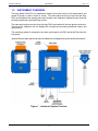
MODEL 4100-LEV Level Monitor User Manual Technical Support Continental North America Toll Free 1-(800) 387-9487 Ph: +1 (905) 829-2418 Fx: +1 (905) 829-4701 A Product of Arjay Engineering Ltd. Oakville, Ontario, Canada www.ArjayEng.com MODEL: HARDWARE NO.: SOFTWARE NO.: SERIAL NO.: 4100-LEV Level-Ease Monitor ENGINEERING Continuous level monitoring of liquids and bulk solids Over 40 years of Arjay’s field proven HF capacitance experience has been applied to the Level-Ease 4100 series monitors. This unique level system provides complete flexibility for monitoring one or more tanks in one complete package. explosion proof probe head • unique capacitance approach eliminates routine cleaning • no moving parts • control and interface panel mounts safely away from the process The Level-Ease 4100 sensing probe monitors the capacitance field between the probe and it’s concentric shield of the tank wall. As the level of product increases, the probe capacitance changes. This level signal is used to provide outputs, displays and relay control. (beacon and buzzer optional) 2” npt 316SS process connection 3/4” npt 316SS process connection Probe with concentric shield for non-metallic, cylindrical horizontal or fuel/oil applications Probe shown with inactive sheath up to 1 km 4100-LEV Features and Benefits Technical Specifications - Control Panel • no moving parts • remote electronics via standard twisted pair • all set-up, calibration and diagnostics are accessed at the control panel • all control wiring and interface is done at the control panel • HF capacitance technology does not require routine cleaning • touch screen interface for easy set-up and user interface • tank view display for ease of reading • trend display of hour, day or month increments Operating Temp. Resolution Accuracy Power Input Display Relay Outputs Enclosure Approvals to Technical Specifications - Probe Process Temp. Ambient Temp. Pressure Optional Interfaces Analog Output Communication 0˚C to +55˚C .007% (.07 pF at 1,000 pF) .04% of full scale pF 24 vdc or 80-240 vac +/-10%, 1P, 50-60 HZ touch screen full colour tank view graphics, % and engineering units of level selectable trend line view or none four SPDT, 10 amp @ 240 vac, dry Type 4 metal painted blue / IP 66 optional Type 4X SS or polycarbonate UL / CSA / CE IEC 61010 4-20 mA non-isolated RS-485 Modbus Process Connection Explosion Proof Intrinsic Safety CRN Wetted Parts -60˚C to +260˚C -60˚C to +55˚C 103 bar/10342 kPA/1500psi at stable temperature available threaded or flanged CSA Div 1, Class 1, Groups C,D Approved Intrinsically Safe when ordered with Approved Barrier in Control Unit CAN/CSA E60079-11: Class I, Groups A,B,C,D; Class II, Groups E,F,G; Class III, Encl.Type 4 ABSA-CRN #OF07450.2 316SS and Teflon Probe materials are eligible for NACE MR-0175 Compliance Control Unit Interface App Board Arjay PMC Probe in Tank Probe Assembly Control Panel The Arjay PMC (pulse module circuit) installed at the probe converts the tank signals to a frequency pulse. This allows the controller to be safely mounted up to 1 km away from the tank with virtually no loss to signal stability. No operator interface is required at the probe using this unique Arjay PMC design. All calibration, control interface and power wiring is done at the main control unit. The touch screen provides a simple menu-driven operator interface and display. The Arjay App board is the heart of the 4100-LEV. This board monitors and controls the signals from the tank probe, applies the appropriate calibration algorithms and interfaces this information to the touch screen and PLC hardware. ENGINEERING Arjay Engineering Ltd. http://www.arjayeng.com 2851 Brighton Road Oakville, Ontario telephone: ++1 905-829-2418 Canada L6H 6C9 N. America toll free: 1-800-387-9487 fax: ++1 905-829-4701 4100-LEV-12a Model: 4100-LEV User Manual TABLE OF CONTENTS 1.0 2.0 3.0 4.0 5.0 6.0 7.0 INSTRUMENT OVERVIEW ............................................................................................3 1.1 Features .............................................................................................................5 1.2 Model Numbers ..................................................................................................5 1.3 Specifications .....................................................................................................6 INSTALLATION...............................................................................................................7 2.1 Main and Remote Panel Installation ..................................................................7 2.2 Probe Installation ...............................................................................................7 2.3 Electrical Installation ..........................................................................................10 2.4 Glossary of Symbols ..........................................................................................11 POWER UP INTRODUCTION ........................................................................................12 3.1 Power Up ...........................................................................................................12 3.2 Screen Menu Background Information ..............................................................12 3.2.1 Keypad Main Menu Entry ....................................................................13 3.2.2 Password .............................................................................................13 SETUP AND CALIBRATION (PARAMETER SETTINGS) .............................................14 4.1 Configure Main Screen View .............................................................................14 4.2 Alarms ................................................................................................................15 4.3 Analog Output ....................................................................................................18 4.4 Buzzer and Strobe Beacon (Optional) ...............................................................18 4.5 Calibration ..........................................................................................................19 4.5.1 Auto Calibration (Two Points)..............................................................20 4.5.2 Manual Calibration...............................................................................21 4.6 Diagnostic Information .......................................................................................22 TROUBLESHOOTING ....................................................................................................24 CONTROLLER SETTINGS SHEET ...............................................................................27 DETAILED ELECTRICAL AND DIMENSIONAL DRAWINGS ........................................29 TABLE OF FIGURES Figure 1 – Instrument System Overview ....................................................................................... 3 Figure 2 – PMC Installation Overview........................................................................................... 8 Figure 3 – Typical Level Application Overview ............................................................................. 9 Figure 4 – Electrical Installation Overview .................................................................................. 10 Figure 5 – Main Screen View ...................................................................................................... 12 Figure 6 – Password Screen View .............................................................................................. 13 Figure 7 – Parameter Settings Screen View ............................................................................... 14 Figure 8 – Configure Main Screen View ..................................................................................... 14 Figure 9 – Alarm Setting Screen Views ...................................................................................... 15 Figure 10 – Examples of differential Level Applications ............................................................. 17 Figure 11 – Analog Output Screen View..................................................................................... 18 Figure 12 – Buzzer & Strobe Setting Screen View ..................................................................... 18 Figure 13 – Pulse Card Set-up Screen View .............................................................................. 19 Figure 14 – Calibration Reminder Screen View .......................................................................... 19 Figure 15 – Auto Calibration Screen View .................................................................................. 20 Figure 16 – Manual Calibration Set-up Screen View .................................................................. 22 Figure 17 – Diagnostic Information Screen View ........................................................................ 22 2 Rev: 1.0 Model: 4100-LEV 1.0 User Manual Rev: 1.0 INSTRUMENT OVERVIEW The Arjay Model 4100-LEV is a capacitance based level monitor used for the measurement and control of liquids or solids in a tank or vessel. The contol panel receives an input from the Arjay PMC card installed at the sensing probe and, through a site calibration, displays the tank level and provides proportional outputs and relay control. The main panel receives an input from the Arjay PMC card installed in the level probe junction box. Through a site calibration, the unit displays the oil depth and provides proportional outputs and relay controls. The monitoring system is comprised of one main control panel, the PMC card at the Probe and the level probe. Optional Remote alarm panels can also be added that will display and provide audio/visual alarms. Figure 1 – Instrument System Overview 3 Model: 4100-LEV User Manual Rev: 1.0 Main Panel The main panel is a wall mounted touch screen monitor to be installed in a general purpose (nonhazardous) location that is accessible for set-up and observation of the display and alarms. Four relays are available. Relay 1, 2 & 3 can be field set to alarm at any % level within the range of the probe. Relay 4 is factory set as a system fault relay. Relay 4 can be set to act as a normal alarm relay. See section 4.2 for instruction to change alarm setup. A 4-20 mA non-isolated output and Modbus RS-485 are optional. The power input at the main panel serves the HMI, PLC, PMC and probe requirements. An optional buzzer and strobe (beacon) are available. The level probe is approved for Class 1 Group C&D hazardous locations and can also be made Intrinsically Safe for Hazardous Classified locations through the installation of an IS Barrier in the main panel. The main panel screen provides additional user interface menus for diagnostics, analog output, calibration, set-up and general help information. Diagnostic Menus can be accessed for viewing at any time but a password entry is required to make setup changes. Remote Panel Remote panels are available to mimic the screen and audio/visual alarms of the main panel. All access to the touch screen menus are password protected on the remote panels. Remote PMC and Sensing Probe An Arjay PMC card is installed in the level probe junction box. This converts the capacitance reading of the tank product into a frequency pulse for transmission to the main panel. This unique approach eliminates any operator interface requirements at the probe. All diagnostics and calibration is done at the main panel. 4 Model: 4100-LEV 1.1 Rev: 1.0 Features 1.2 User Manual Touch Screen interface with passcode protection Microprocessor based Controller Optional Strobe / Buzzer Level Display in % and engineering units Diagnostic, set-up and Help menus on all screens Four alarm relays Optional analog outputs and RS-485 communication Arjay PMC Card input Model Numbers 4100‐LEV ‐ a ‐ b c d e f 2 - n/a 3 - n/a 4 - 24 VDC ‐ h h – Custom vs. Standard x – Custom** z – Standard **Fill in the custom requirement below. b - Enclosure 0 – No 1 – Type 4/IP65 Steel 2 – Type 4X/IP65 Poly 3 – Type 4X/IP65 SS 9 – Custom a - Power Input 1 - 100-240 VAC g c – Strobe Beacon 0 – No 1 – Yes d – Buzzer 0 – No 1 – Yes x – Custom Description e – 4-20mA Output 0 – No 1 – Yes f – RS-485 Modbus Communication 0 – No 1 – Yes g – Instrinsic Barrier 5 1 0 0 0 ‐ z Standard Configuration Selected 1 No Intrinsic Barrier Selected 1 No RS-485 Selected ‐ No 4-20mA Selected 1 Strobe Selected ‐ 100-240 vac Power Input Selected 4100‐LEV Steel Enclosure Selected Example: Buzzer Selected 0 – No 1 – Yes Model: 4100-LEV 1.3 User Manual Rev: 1.0 Specifications Power Input: 100-240 VAC +/- 10%, 50/60 Hz, (1.22A 24 vdc, 2.5 amp MAX (Optional) 0.66A) 1.6A fuse User Interface: Touch Screen Full Colour 6 “ display on Main Panel Monochrome 4” on Remote Panel Outputs: Alarm Relay Output DPDT relay, 8 A @ 250 VAC dry contacts Selectable failsafe or non-failsafe Programmable time delay: 0 – 60 minutes ON and OFF Three relays for setpoint alarms One relay for system fault alarm (Selectable) Analog (Optional) 0/4-20 mA non-isolated, 600 ohms Self powered -Direct or Indirect Communication (Optional) RS-485 Modbus Probe Input: Capacitance Probe with PMC input Accuracy: 0.04% of full scale pF Resolution: 0.007% (0.07pF at 1000pF) Environmental: Ambient Temperature Controller 0 to +55 °C PMC -60°C to +55 °C Level Probe -60°C to +260 °C Process Pressure 103 bar / 10342 kPA /1500 psi Relative humidity 0 to 95% (non-condensing) Installation Category II Pollution Degree 2 Mechanical Specification: Refer to dimensional drawing 6 Model: 4100-LEV 2.0 User Manual Rev: 1.0 INSTALLATION NOTE: If any damage to the instrument is found, please notify an Arjay Engineering representative as soon as possible prior to installation. 2.1 Main and Remote Panel Installation Choose a mounting location in accordance with good instrument practice. Extremes of ambient temperature and vibration should be avoided (see specifications and installation drawing). Remote mimic panels can be mounted up to 300 meters away from the main panel. The PMC and level probe can be mounted up to 1 km away from the main panel. Important Note: The controller can be set in a Failsafe mode. This means that the relays are in an energized state during normal operation. The N.O. relay contact will be held closed and the N.C. relay contact will be held open during a normal condition. This will allow the relay to return to it’s non-energized (shelf) state during an alarm, fault or power failure condition. 2.2 Probe Installation Capacitance probes may be selected from a variety of styles for use with liquids, liquid interfaces, and granular materials. The probe length is customer specified based on the tank dimensions and required depth into the material being measured. Usually Teflon coated probes are used. Typical probe entry into a tank requires a 3/4” NPT opening (standard probes), 1” NPT opening (heavy duty probes), or 2”NPT (shielded probes). Flanges and concentric shields are available as options. The entrance configuration may vary depending on the application requirements. Use a wrench on only the lower half (tank side) of the probe fitting when installing or removing the probe from the tank or flange. The probe fittings are compression type with Teflon ferrules assembled by applying torque between the two fitting sections. The fittings are sealed at the factory to provide a compression seal capable of withstanding high pressures. Once opened they cannot be reassembled without new ferrules. The probe should be mounted vertically and parallel to a reference ground surface for best accuracy. This is typically the vertical wall of the tank or a concentric shield around the probe. The following points are important when installing the probe: 1. Reference ground: This is important and is typically the metal walls of the tank. For non-metallic tanks, a concentrically shielded probe is required which provides its own Ground. IMPORTANT: For threaded entry and flange entry probes, make sure the threads are clean to ensure a good electrical ground connection between the tank, flange and fitting. 2. The distance between the probe and the ground reference: This only applies to probes without concentric shields. The closer the distance to the tank wall, the greater the sensitivity of measurement; too close and bridging problems may occur. 3. The degree of parallelism between the probe and the reference ground: The probe must be parallel to the reference ground for a linear output signal. Note: the concentric shield option is inherently linear due to the concentric shield. 7 Model: 4100-LEV User Manual Rev: 1.0 4. Temperature change of the material in the tank. The amount of measurement error depends on the material. If the temperature change is excessive, temperature correction may be required. 5. Agitators or moving objects in the tank: Moving objects in the tank close to the probe such as agitator blades, moving baffles etc. appear as moving ground references to a capacitance probe and can cause measurement errors. In applications where these objects are present, a concentrically shielded probe should be used. 1. Remove probe junction enclosure cover. 2. If PMC 2800 is not already installed, mount onto the standoffs in the base of the probe junction enclosure. 3. Remove the mating connector and wire it as shown. 4. Make sure junction box is electrical grounded. Figure 2 – PMC Installation Overview 8 Model: 4100-LEV User Manual Figure 3 – Typical Level Application Overview 9 Rev: 1.0 Model: 4100-LEV 2.3 User Manual Rev: 1.0 Electrical Installation Refer to the drawings provided by the contractual engineer for your project and the drawings included with this manual. Figure 4 – Electrical Installation Overview Wiring The main control panel supplies a 24 VDC power signal to the PMC at the probe. When the PMC is connected, the voltage is 8 -10 VDC. The PMC card drops a frequency pulse onto the power wiring for a return signal to the main control unit. Required wiring between the PMC and the main control unit is two conductor shielded hookup cable. A typical wiring type is 18AWG two conductor shielded (Belden #8760 or equivalent). *Shielded wire is required on all installations. Maximum wire length is 1km between controller & PMC junction box. Refer to the detailed electrical drawings included at the back of this manual. 10 Model: 4100-LEV 2.4 User Manual Rev: 1.0 Glossary of Symbols Attention, consult accompanying documents Attention, veuillez consulter les documents ci-joints. Protective Earth Terre de protection Fuse Coupe-circuit; fusible Direct Current (DC) Courant continu Normally open relay contacts Contacts travail Normally closed relay contacts Contacts Repos Power off ArróÕ (mise hors tension) Power on Marche (mise sous tension) N L G Neutral Neutre 11 Live Sous tension Ground Terre Model: 4100-LEV User Manual 3.0 POWER UP INTRODUCTION 3.1 Power Up Rev: 1.0 Check that the power wiring and connections to the main panel, remote panel, PMC card at the Probe and interfaced equipment are wired in accordance with the electrical installation drawings. Power On the unit. The main screen will light up and run through initialization. After any power interruption, the system will run through this same 30 second initialization. The main and remote panels are set to factory defaults or customer specifications. After the initial installation, the alarm and output functions must be set by the customer and a process calibration is required. These entries are retained in the CPU memory and are not required after any further power disruption. Confirm the screen reads similar to the following. OIL/WATER SEPARATOR LEVEL MONITOR Figure 5 – Main Screen View 3.2 Screen Menu Background Information The Trend View logs and provides a graphic display of the level readings during the past 10 days. This view can be hidden. (Press “No Trend” icon). In addition to the standard % display, the screen will display in any engineering units entered. Note that the engineering units must be directly proportional to the % level for the reading to be accurate. For example, a volume in liters will be proportional to a level in a vertical straight walled tank but will not be proportional to a level in a cylindrical tank. The full scale value of units, such as liters or mm at the determined 100% maximum level will be required to be entered during calibration. 12 Model: 4100-LEV User Manual Rev: 1.0 3.2.1 Keypad Main Menu Entry Below the touch screen are 4 touch keys. Home At any time, you can press the Home Key to return directly to the Home Screen Help This provides serial number information and an overview of the system operation and components. Contact details for technical help are included at the end of the text. Tools Access this section to view or configure the screen and control settings, view diagnostics and perform a calibration Buzzer Silence During an alarm condition the audio can be silenced. Silencing at any panel will silence all panels. The audio alarm will automatically re-set when the alarm clears. 3.2.2 Password This model has a touchscreen display. Tap the icon that you wish to change. A keyboard will display for your changes. Press the Return Key to complete. Accessing any screen that allows parameters to be changed will require a password. The factory password is 2000. Touch within the Password box, a keyboard will display. After the password is entered, press the Return key to complete. Then press OK in Logon screen. Menus can then be accessed. Figure 6 – Password Screen View 13 Model: 4100-LEV 4.0 User Manual Rev: 1.0 SETUP AND CALIBRATION (PARAMETER SETTINGS) This section describes the screen, alarm and interface features accessed through the Main Panel. See Controller Setting Sheet (Section 6.0) in back of manual for Factory Default values. Press “ “ Figure 7 – Parameter Settings Screen View Enter into the following menu items to configure your monitor. 4.1 Configure Main Screen View Figure 8 – Configure Main Screen View The Password 2000 will be required to make changes in this section. Title: You can personalize the main screen title to your application or tag # (ie, Separator #6 LT-4505). Touch the TITLE block and type in your description. The factory default is 4100LEVEL MONITOR. Filtering Filtering is used to suppress rapid spikes by adding time delay to the response rate. For example, a sudden change of 40% could cause a valve to move too quickly and upset the process conditions. Adding 10 seconds of delay will dampen the display measurement and mA output so that it approaches the 40% change over a period of 10 seconds. If the level returns to a lower point, the mA will follow the new path with the same dampening affect. 14 Model: 4100-LEV 4.2 User Manual Rev: 1.0 Alarms The Password 2000 will be required to make changes in this section. There are three Alarm setpoint relays, and one fault relay (Factory default). Relay 4 is factory defaulted as a Fault relay.Relay 4 can also be used as general purpose relay. To set relay 4 as general purpose relay, press “Enabled Relay 4 as fault relay” on the screen to disable the factory default relay setting. Relays 1, 2 & 3 are for general purpose use for alarms, valve control, etc.. Figure 9 – Alarm Setting Screen Views To set up Relays 1, 2, 3 and 4**, Enter the “Config other relays” icon. If the icon beside each Relay indicates Enabled, the relay is functional. Pressing the Enabled icon to display Disabled will render the relay Disabled and will remove that relay from the main screen display. It will disable the relay from functioning. If it presently reads Disabled, touch the icon to Enable the relay. Relays may be desired to alarm outside of the normal 100% operating range. As such, these can be set at any value from 0 to 200% and in any order. **If selected as general purpose only. Touch Relay 1 icon so that it is green. Enter the values of parameters described below. (See table 1 for Effect of the relay action and failsafe). Setpoint ON This will determine the setpoint level in % at which the alarm relay activates. Setpoint Off This will determine the setpoint level in % at which the alarm relay will turn off. This differential feature is used to suppress chattering of alarms if the level is hovering at the setpoint or can be used to control the differential on/off of a pump or valve. (See Figure 10 for examples of differential for pump applications). Time Delay Delay ON. This is the time, in seconds, that the relay will delay before activating when the alarm setpoint has been reached. Delay ON is used to suppress a nuisance alarm that may be caused by a spurious or momentary alarm condition. 15 Model: 4100-LEV User Manual Rev: 1.0 Delay OFF. The time, in seconds, that the relays will stay on after the level has returned to a normal condition. Delay OFF is used to keep controls activated after the alarm has cleared to ensure a stable normal condition has been reached. Alarm Above or Below Setpoint This function is to guide the controller on how to control the failsafe and LED indications on the screen. Select ABOVE if the requirement is for the relay to alarm when the % level rises above the setpoint. Select BELOW if the requirement is for the relay to alarm if the % level drops below a setpoint. The parameters are now set for relay 1. Repeat the above steps for the rest of the Enabled relays. Failsafe Failsafe will determine if the relays are energized or de-energized during a normal operating state (no alarm condition). If Failsafe is YES, the relay will be energized during a normal operating condition. An alarm or power failure will de-energize the relay to the alarm state. When in Failsafe mode and during a normal condition, the N.O. contact is closed and the N.C. contact is open. WIRE ACCORDINGLY. TABLE 1: The following table shows the effect of the Relay Action and Failsafe settings. Under normal conditions, the alarm would show “Green”. Relay Failsafe Effect Action Setting Above No Alarm condition when process level rises above the On Setpoint for at least the alarm delay period. Alarm condition remains active until the process level drops below the Off Setpoint. No action is taken when the process level is between the On and Off differential Setpoint. In the alarm condition, the corresponding alarm turns Red, and the relay is energized. Above Yes Alarm condition set and reset as above. In the alarm condition, the corresponding alarm turns Red, but the relay is de-energized. Below No Alarm condition when process level drops below the Off Setpoint for at least the alarm delay period. Alarm condition remains active until the process level rises above the On Setpoint. No action is taken when the process level is between the On and Off differential Setpoints. In the alarm condition, the corresponding alarm turns Red, and the relay is energized. Below Yes Alarm condition set and reset as above. In the alarm condition, the corresponding alarm turns Red, but the relay is de-energized. 16 Model: 4100-LEV User Manual Figure 10 – Examples of differential Level Applications 17 Rev: 1.0 Model: 4100-LEV 4.3 User Manual Rev: 1.0 Analog Output Figure 11 – Analog Output Screen View The Passcode 2000 will be required to make changes in this section. 0-20mA vs 4-20mA Select the mA output range for your application. The green icon will confirm which range is selected. 0/4 mA = 0 and 20 mA = xx% The 0 or 4 mA is factory defaulted to 0 % level. The 20 mA may be offset to suit your control requirements and is entered in %. Typically 20 mA is set to the 100% level of product. For maintenance purposes to check external equipment and alarms or the analog output, the mA output can be forced by pressing the “Force” icon beside “Force a 20mA output”. mA Action Direct mA output – 0% Level = 4mA, Span Level (e.g. 100%) = 20mA Indirect mA output – 0% Level = 20mA, Span Level (e.g. 100%) = 4mA 4.4 Buzzer and Strobe Beacon (Optional) If a Buzzer or Strobe Beacon is ordered, they are factory wired to internal relays. They can be set in the same way as the Alarm relays. See section 4.2. The buzzer can be silenced by the keystroke button “ ” on the main screen”. It will automatically reset. The strobe can be selected to latch. If latch is chosen, an icon will display after an alarm to clear. Figure 12 – Buzzer & Strobe Setting Screen View 18 Model: 4100-LEV 4.5 User Manual Rev: 1.0 Calibration After the above setup parameters have been entered for the application a calibration is required. Enter the calibration menu. A Pulse Card set up will be required. Confirm the current A, K and C values shown on the screen match with the values provided on the label of the PMC card installed in Junction box. If the values are different, Press the “Change” button on the screen. Enter the A, K and C values and press “Enter”. The screen will indicate “Entered”. Figure 13 – Pulse Card Set-up Screen View Calibration Reminder The 4100-LEV has a real time clock. After calibration, the calibration date is recorded in the diagnostics. A calibration reminder can be set for up to 999 days. This feature can be enabled by pressing the “ENABLE CALIBRATION REMINDER” icon. This icon will appear again on the main screen after the preset number of days is reached. If a calibration can be done, Press the “Recalibration” icon. If a calibration cannot be performed at the time of the reminder, this can be reset to a later date by entering the number of days until the next reminder is desired. Press “Enter” icon to activate the Reminder countdown. Figure 14 – Calibration Reminder Screen View 19 Model: 4100-LEV User Manual Rev: 1.0 4.5.1 Auto Calibration (Two Points) After the setup parameters have been entered for the application, a process calibration is required. Two calibration points will need to be entered. The tank level will need to be changed, up or down, by at least 10% to enter these two points. The actual levels in the tank will need to be determined as accurately as possible. The greater the change between the two points the better. For example, a 1% error in the entered level value for a 25% change translates to a 4% error at Full Scale. To Calibrate. Enter Proceed to Auto Calibration. Figure 15 – Auto Calibration Screen View Note that a capacitance reading in pF is displayed in the upper left of the screen. This is a realtime reading of the tank capacitance. If filtering has been used then the user must wait until capacitance reading has stabilized before capturing. 100% Level Depth The instrument needs to know what 100% will be. Enter the value that 100% represents in your chosen engineering units. ie. Litres might be 36000, mm might be 4520, etc. The factory default is millimeters (mm). You can change this to any units of your choice by touching the engineering unit icon and entering your desired engineering units such as inches, mm, cm, liters, etc. Note: Any change in units will require a change in the value used for 100% depth. After the above has been entered, Press ENTER. Enter Point 1 Enter a value, in %, of the level and then press Enter to confirm and “Entered” will display. This percentage will be displayed on the screen. Use a percentage value that indicates your process operation. For example, a tank may be 3000 mm tall, but for process operations, 100% may be considered as 2800mm. Make sure level is at the specified % Level and press “Capture. The new capacitance value in pF and “Captured” will display. If entered properly the new value should be same as capacitance value shown. In upper left of screen. Enter Point 2 After Point 1 is entered, the actual level in the tank will need to be changed. Change the level up or down. The greater the change, the greater the accuracy. The pF reading in the upper left` screen will rise or lower accordingly to confirm that a change is being registered. Enter a value in % of the second level point and then press Enter to confirm and “Entered” will display. 20 Model: 4100-LEV User Manual Rev: 1.0 Raise or lower level in tank to the specified % level and press capture to confirm. The new capacitance value in pF and “Captured” will display. If calibration was not successful an error message will occur. Common problems are either level in tank was not changed or the 2nd level value in % was entered identical to 1st point. Calibrate If all points are “Entered” and “Captured” then “Calibrate” icon will display on bottom of screen. Press the Calibrate Icon. Calibration will be confirmed “Calibration OK!”. Press the Home Key to return to the main screen. 4.5.2 Manual Calibration Manual calibration allows a user to override any of the previous calibration values and enter predetermined or observed calibration values. This feature may be used for a number of different reasons. For example. 1. One of the calibration points is desired to be re-calibrated. The user can view the pF reading of the probe in the Diagnostics menu and also record the actual level in the vessel at the same time. These values can then be entered in the Manual Calibration to change either Cal Point 1 or Cal Point 2. 2. If a calibration was done using 20% and 60 % as the two values (for example), but it was determined a future date that the 60% should have been entered as 70%. 3. The process level cannot be altered at the time of calibration so a random pF value and % level value is entered as the second point to allow operations until a proper second point can be entered. See method in 1 above. To Calibrate. When you enter to the manual calibration mode, the calibration points from the Auto Calibration will be shown. Change value then Press Enter if any of the 2 points needs to be changed. Press enter to the reading points and Calibrate icon will appear. Calibrate Press the Calibrate Icon. Calibration will be confirmed “Calibration OK!”. If calibration was not successful, an error message will occur. Common problems are either level in tank was not changed or the 2nd level value in % was entered identical to 1st point. Press the Home Key to return to the main screen. 21 Model: 4100-LEV User Manual Rev: 1.0 Figure 16 – Manual Calibration Set-up Screen View The Arjay 4100-LEV is now set up, calibrated and operating to your process conditions. 4.6 Diagnostic Information Figure 17 – Diagnostic Information Screen View These are only View Only screens. They provide various diagnostic information that is communicating between the probe and the controller or has been entered during a calibration. This is a real-time display and is a valuable tool to observe process data such as product stability and change. If technical assistance is required during the setup or operation of the instrument, record or photograph these screens prior to contacting Arjay. Oscillation Frequency: This is the frequency at which the probe is tuning itself as the product level changes. The frequency change is inverse to level. 0 Hz indicates there is no frequency to the pulse card and the probe may be disconnected. Frequency: For stability and transmission to the main controller, the oscillation frequency of the probe is divided and linearized to a lower frequency in the PMC card. This response is also inverse to level. Capacitance: This is the total probe, product and tank capacitance reading in picofarads. At 0% level there will be an offset capacitance due to the physical length of probe and alliance to the tank wall. If the probe wire is not connected to the PMC card properly, this will be near or at 0.0 pF. Filtered Capacitance: During the screen set-up, there will be an opportunity to filter the output to dampen spikes. If filtering has been entered, this reading will respond slower than the true process capacitance. Level: If a calibration has been done, the % level reading is available here. Level Depth: If a calibration has been done, the engineering unit reading is available here. Press “More” to view more data: PMC: During calibration, the operator is required to enter the A,K, C values that are labeled on the PMC card as well as in the back of the manual under controller settings (Section 6.0). These 3 values are unique to each PMC card and enhance the response, accuracy and linearity of the tank capacitance for optimum performance. 22 Model: 4100-LEV User Manual Rev: 1.0 Depth for 100%: During calibration, the operator will be required to enter a value in height OR volume that represents 100%. This is the value that was entered with the selected engineering units. Slope: After calibration, the ARJAY cpu will determine the pf per % change for tank application. This is used internally to extrapolate a zero and span. Offset: The offset is the capacitance of the Probe in the vessel under a 0% level condition. Calibration Points: These are the calibration values recorded after the last successful calibration. Last Calibrated: During a successful calibration, the calibration date will be recorded. 23 Model: 4100-LEV 5.0 User Manual TROUBLESHOOTING Main Panel Press “ ” for some troubleshooting tips. Condition: Power Supply Status Confirm the Power Supply LED is active (Green). GREEN LED Condition: Power Input Status Confirm the Power input is 100-240 VAC using a meter. Confirm if input fuse has blown. Condition: Communication Error Means no communication between 4100 Signal Converter (A00740) and RS485 Communication Module. Under normal operating conditions, both LED’s should be Lit and Flashing continuously. Check wiring between 4100 Signal Converter (A00740) and RS485 Communication Module. Confirm 24VDC power to 4100 Signal Converter (A00740). 24 Rev: 1.0 Model: 4100-LEV User Manual Rev: 1.0 Condition: No Transmitter Signal (Status LED is Red) Under normal operating conditions, LED 2 should be Green. If there is an error, LED 1 goes Red. Make sure the PMC-2800 is installed. Make sure the PMC-2800 wiring is correct and there are no breaks in the wiring. At the PMC-2800, measure across the + and - terminals with a DC meter. Make sure “Common” lead of meter is on ‘-‘ terminal. It should read (+) 8 to (+)10 VDC with the PMC-2800 connected and approximately 21-24 VDC with the PMC-2800 terminal disconnected from pulse card. The unit is not receiving a frequency signal from the remote PMC-2800 level transmitter in the probe head: Check wiring. Disconnect probe from pulse card to ensure that probe is not pulling down the signal. pF reading should be ~ 0.0 pF with no probe hooked up. Replace PMC-2800 if suspect water damage OR possible power outage may have damaged the pulse card. If wiring checks out: call Arjay Technical Support. Condition: Signal out of Range Check the integrity of the Teflon sheath of the probe. If this has been damaged, water could cause an electrical short circuit between the probe within the Teflon sheath and the ground reference. In this case a very high capacitance is usually registered. Check the capacitance reading in diagnostics menu. To confirm: Open the probe head and disconnect the blue wire from the probe to the PMC-2800. Using a DVM, measure the resistance between the enclosure case and the probe tip. It should read infinite resistance or OL. Make sure that fingers and hands do not touch the metal portion of the probes of the DVM since this could show a lower resistance: 110mohms. OIL/WATER SEPARATOR LEVEL MONITOR Condition: PLC Error If LCD display shows “##”, check the condition of Ethernet wire connected bwteen HMI display and PLC unit for no breaks. Make sure the Ethernet wire is not lose from PLC or HMI terminal. 25 Model: 4100-LEV User Manual Rev: 1.0 Condition: Reading not Accurate For probes without a factory supplied concentric shield, make sure the probe is parallel to its ground reference which may be the tank wall or the inside of a stilling pipe (if probe is installed in a pipe). May require fine tuning – use manual calibration if changes are required to one of the cal points. 26 Model: 4100-LEV 6.0 User Manual Rev: 1.0 CONTROLLER SETTINGS SHEET Checked by Model Number Serial Number Software Rev. PARAMETER DESCRIPTION PMC A value PMC-2800 setup parameters PMC K value PMC-2800 setup parameters PMC C value PMC-2800 setup parameters Engineering Unit Chosen engineering units for depth of product. Slope Offset Depth for 100% Capacitance change per % change after successful calibration. Result of a successful Calibration: Calculated capacitance for 0% level. Full scale engineering units value in height or volume. FACTORY SETTING mm 1000mm Zero Zero Level value for mA output. 0.0% Span Full Scale level value for mA output. 100% mA Range 0-20mA OR 4-20mA mA Action Relay 4 (Fault) Relay 4 Failsafe Relay 3 Hi Set 4-20mA - Direct (20mA when level at span) OR - Indirect (4mA when level at span) This relay indicates Instrument Failure. It can also be selected as an Alarm Relay. This relay is factory default to be normally energized (no alarm) and de-energized in an alarm condition or power failure. Alarm Relay 3 high alarm: alarm condition if level is above this value. Direct Fault ON 60% Relay 3 off Alarm relay 3 differential off value 55% Relay 3 Failsafe Failsafe ON sets the relay as normally energized (no alarm) and de-energized in an alarm condition. ON Relay 3 Alarm Action Alarm action above OR below alarm level Relay 3 Alarm Delay (on) Relay 3 Alarm Delay (off) Relay 2 Hi Set Amount of time the level must be in an alarm condition (based on Relay 3 alarm value and Action settings) before the relay trips to the alarm condition (condition set by Relay 3 Failsafe setting). Amount of time the level must stay in an alarm condition (based on Relay 3 alarm value and Action settings) before the relay trips to the normal condition (condition set by Relay 3 Failsafe setting). Alarm Relay 2 high alarm: alarm condition if level is above this value. 27 Above 0 sec 0 sec 40% USER SETTING Model: 4100-LEV User Manual Rev: 1.0 Relay 2 off Alarm relay 2 differential off value 35% Relay 2 Failsafe Failsafe ON sets the relay as normally energized (no alarm) and de-energized in an alarm condition. ON Relay 2 Alarm Action Alarm action above OR below alarm level Relay 2 Alarm Delay (on & off) Relay 2 Alarm Delay (off) Relay 1 Hi Set Relay 1 off Relay 1 Failsafe Relay 1 Alarm Action Relay 1 Alarm Delay (on & off) Relay 1 Alarm Delay (off) Filter Tag Number (Optional) Amount of time the level must be in an alarm condition (based on Relay 2 alarm value and Action settings) before the relay trips to the alarm condition (condition set by Relay 2 Failsafe setting). Amount of time the level must stay in an alarm condition (based on Relay 2 alarm value and Action settings) before the relay trips to the normal condition (condition set by Relay 2 Failsafe setting). Alarm Relay 1 high alarm: alarm condition if level is above this value. Alarm relay 1 differential off value Failsafe ON sets the relay as normally energized (no alarm) and de-energized in an alarm condition. Alarm action above OR below alarm level Amount of time the level must be in an alarm condition (based on Relay 1 alarm value and Action settings) before the relay trips to the alarm condition (condition set by Relay 1 Failsafe setting). Amount of time the level must stay in an alarm condition (based on Relay 1 alarm value and Action settings) before the relay trips to the normal condition (condition set by Relay 1 Failsafe setting). Digital Filter response time in seconds. Used to smooth out level fluctuations caused by splashing etc. For network applications only. All Arjay 4100 series controllers connected to a network must have a unique Tag Number between 1 and 100 Strobe (Optional) Alarm value for strobe. Buzzer (Optional) Alarm value for buzzer. Above 0 sec 0 sec 20% 15% ON Above 0 sec 0 sec 0 sec 1 90% 85% 90% 85% 28 Model: 4100-LEV 7.0 User Manual Rev: 1.0 DETAILED ELECTRICAL AND DIMENSIONAL DRAWINGS Drawings are included in this section that are specific to your model ordered. If drawings are not included here, record the serial number on the left outside wall of the main panel and contact: ARJAY ENGINEERING TECHNICAL SUPPORT (800) 387-9487 +1 (905) 829-2418 www.arjayeng.com 29