1
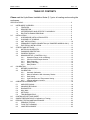
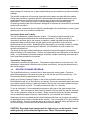
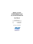
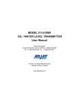
HYDROSENSE 2410 On-line Oil in Water Monitor User Manual Arjay Engineering Ltd. Oakville (Toronto), Canada, L6H 6C9 Tel . ++1 (905) 829-2418 Fax. ++1 (905) 829-4701 North America 1-800-387-9487 www.arjayeng.com [email protected] HydroSense -2410 ppm Oil in Water Monitor ENGINEERING On-line monitoring for ppm concentrations of petroleum oils in effluent and produced water The HydroSense 2410 is the engineered combination of three unique designs by Arjay. The sensing chamber contributes a continuous controlled water sample while the optical sensor package hovers above the passing stream. The Arjay controller then monitors the multiple signals to provide a reliable ppm concentration output. • non-contacting sensor design minimizes system maintenance • fluorescence technology is selective to petroleum hydrocarbons by targeting their aromatic faction • continuous on-line monitoring without chemicals or lag time The HydroSense 2410 uses a UV fluorescence technique to target the aromatic component of the oil contamination. Through a site calibration this aromatic tag provides an indication relative to total oil. A continuous sample flow is tapped or pumped off the process line and directed through the HydroSense chamber. It passes behind the noncontacting UV light source and is targeted with filtered light energy. The soluble and emulsified oils in the water will excite from this light energy and fluoresce light energy back out of the water at a signature wavelength. The intensity of light energy at this wavelength is measured to provide an indication of the ppm concentration. The backlit 4-line display provides easy menu driven commands for set-up, calibration, and diagnostics. Available accessories include air pressurization/purging systems, sample coolers and pumps. HydroSense -2410 ppm Oil in Water Monitor System Maintenance To ensure a long term and reliable operation a routine maintenance schedule should be implemented. Arjay has made this operation quick and easy. The following are a few of the standard maintenance and design features built into every unit. • The sensing chamber is hermetically sealed from the upper control unit. This not only keeps the control components dry but also allows keypad and wiring access without opening the sensing chamber. • Operator clean time is less than 2 minutes and no tools are required for any procedure. Power or sample flow do not need to be turned off. • Lamp replacement is equally easy. A sensor independently monitors the lamp life. The LCD display and a maintenance relay will warn of an impending need for replacement so an operator can schedule this replacement without any downtime. • Full diagnostics are accessed on the LCD display. • The system automatically compensates for temperature and zero calibration (offset) shifting due to lamp aging. • The system automatically compensates for background or stray light energy. • The controller reads the sample over 50 times per second and averages these readings to provide an updated output. • The unique glass flow plate design provides a stable representative sample of the passing stream. • All modular components are plug-in for easy servicing The unique sensing chamber design allows easy access to the controls and wetted components. The lamp/receiver unit is simply lifted and placed onto the convenient door rack. For any routine cleaning, the flow plate can be wiped in place or removed. HydroSense- 2410 Features and Benefits • The special UV absorbing flow plate sheens the water over a large surface area. The resulting high surface area to depth ratio provides many benefits. • The sensitivity to oil molecules is increased by maximizing the optical viewing area • The minimal depth discourages oil molecules from ‘hiding’ behind particulates in the water • The large lamp source targets the water from multiple angles to get a representative sampling of all oil • The large sample target area ensures a representative and stable snapshot of the water conditions • The unit can tolerate suspended solids up to 400 mg/l • non-contacting optics minimizes maintenance • compensation for temperature and lamp degradation minimizes recalibration requirements • alarm warns of impending lamp replacement • long life lamp expectancy of 18 months • continuous on-line monitoring reads the water 50 times/second with an averaged display update every one second • no consumables or chemical used • sample flow gravity outfalls to drain • available with CSA Zone 2 approval or with NFPA/ATEX Pressurization Systems for Zone 2 • designed for harsh environments with a 316 SS housing • no tools necessary for routine maintenance or lamp replacement • the flow or power does not require to be turned off during routine maintenance • flow chamber diversion system conditions and clarifies sample • multi-point calibration available to customize response curves • overflow baffle de-aerates bubbles • certified to IMO MPEC.107(49) when interfaced with site logging and by-pass requirements HydroSense -2410 Performance Technical Specifications - Control Unit The performance is based on the site calibration to a known hydrocarbon concentration in stable background water. Changes in hydrocarbon make-up and background stability may affect the output. Through a simple calibration, this unit correlates well with laboratory ISO and EPA methods. Range user selectable 0-10 ppm to 0-5,000 ppm minimum alarm setpoint 3 ppm 0.1 ppm Display Resolution Instrument Accuracy +/- 0.1 ppm Process Accuracy +/- 1.0 ppm under stable conditions Oil Type All PAH hydrocarbons, free and dissolved Sensitivity 145 ppb diesel reference 463 ppb crude reference Ambient Operating Temp. 5˚C to 55˚C (best accuracy between 10˚C to 40˚C) Protect from direct sun or rain. Instrument shelter or indoor use is recommended. Air Conditioners available. Ambient Process Temp. 0˚C to 40˚C (optional cooler for temperatures >40˚C) Power Input 24 vdc or 110 vac or 220 vac Alarm Relays 4 x 10 amp, SPDT, dry Output 4-20 mA, Isolated Interface RS-485 standard (optional HART and FF modules) Standards UL, CSA, CE, ABS, CSA Div 2, T3C Groups A,B,C,D, Zone 2. Pressurization / Purge available for use in Zone 2. NFPA / ATEX. IMO MPEC.107(49) Certified (see site interface requirements) Enclosure 316 SS, Type 4X, IP65 All calibration, relays, signal outputs and power wiring are available at the main control unit. separated for trend view HydroSense 2410 Laboratory Spectrophotometer documented field results from offshore oil platform (Jan 24 – Mar 04 '02) The HydroSense 2410 correlates well against laboratory methods and is ideal for process trending and continuous on-line monitoring. ENGINEERING Arjay Engineering Ltd. http://www.arjayeng.com 2851 Brighton Road Oakville, Ontario telephone: ++1 905-829-2418 Canada L6H 6C9 N. America toll free: 1-800-387-9487 fax: ++1 905-829-4701 Model: HS2410 User Manual Rev: 4.2 TABLE OF CONTENTS Please read the HydroSense Installation Notes (2.1) prior to locating and mounting the enclosures. SPECIFICATIONS .......................................................................................................................3 1.0 INSTRUMENT OVERVIEW ............................................................................................5 1.1 FEATURES ........................................................................................................5 1.2 DESCRIPTION...................................................................................................5 1.3 INTERFERENCES AND AFFECTS TO ACCURACY .......................................6 1.4 ROUTINE CLEANING PROGRAM ....................................................................7 2.0 INSTALLATION...............................................................................................................8 2.1 HYDROSENSE INSTALLATION NOTES ..........................................................8 2.2 GLOSSARY OF SYMBOLS ...............................................................................9 2.3 UNIT INSTALLATION ........................................................................................10 2.4 PERMANENT POWER CONNECTION (AC POWERED MODELS ONLY) .....10 2.5 ELECTRICAL INSTALLATION ..........................................................................11 3.0 STARTUP AND SETTINGS ............................................................................................12 3.1 NOTES ON VALUE ENTRY ..............................................................................12 3.2 PASSWORD PROTECTION .............................................................................13 3.3 POWERUP DISPLAY ........................................................................................13 3.4 MINIMUM SETUP (<CONTROL> Key) ............................................................13 3.4.1 Operation Range (4-20 mA Setting) ....................................................13 3.4.2 Confirm 4-20mA output direction.........................................................13 3.4.3 Relay Setpoints ...................................................................................13 3.4.4 Relay Time Delay ................................................................................14 3.4.5 Relay Enable .......................................................................................14 4.0 CALIBRATION ................................................................................................................15 4.1 BEFORE CALIBRATION ...................................................................................15 4.2 CALIBRATION ...................................................................................................15 4.2.1 Automatic Calibration ..........................................................................15 4.2.2 Manual Calibration With Laboratory Results .......................................16 4.2.3 Gain Setting .........................................................................................16 4.2.4 Light Reference and Temperature Setting ..........................................16 4.2.5 Change calibration location .................................................................17 5.0 OPERATION & DIAGNOSTICS ......................................................................................18 5.1 AMPLIFIED SIGNAL ..........................................................................................18 5.2 UNAMPLIFIED SIGNAL .....................................................................................18 5.3 DIAGNOSTICS ..................................................................................................18 5.4 MIN / MAX ..........................................................................................................18 5.5 SETTINGS .........................................................................................................18 5.6 TROUBLESHOOTING .......................................................................................19 6.0 CONTROLLER SETTINGS SHEET ...............................................................................20 7.0 SAMPLE PREPARATION (For Calibration or Testing) ..................................................21 8.0 PERIODIC TESTING AND MAINTENANCE ..................................................................22 8.1 PERIODIC TESTING .........................................................................................22 8.2 FLOW TILE CLEANING .....................................................................................22 8.3 LAMP REPLACEMENT .....................................................................................23 -2- Model: HS2410 User Manual Rev: 4.2 SPECIFICATIONS Power Input: 100 -130 VAC*, 207 - 253 VAC* 50/60 Hz, 200 VA max, 24 VDC @ 3.5 A max User Interface: Display Four line LCD with simultaneous display in PPM, Cal Location, current temperature, and bar graph Communication Interface: RS-485 Modbus, optional HART or Fieldbus Foundation module for uni-directional communication of ppm. Relays / Analog Outputs: Relay Outputs 4 independent SPDT, 10 amp (7 amp if used in Class I, Div 2 applications), dry contacts with LED panel indication 2 setpoint alarm relays (R1 & R2): user settable alarm points and delay time (0-99 seconds delay on) 1 maintenance alarm relay (R3) 1 Lamp or controller failure alarm relay (R4) mA Signal Output 4-20 mA DC, 900 Ohms, isolated, field scalable Instrument Performance: Measuring Range 0 - 5000 ppm Hydrocarbon in Water Instrument Accuracy ± 0.1 PPM Process Accuracy +/- 1.0 ppm typical The process accuracy is reflected by the site calibration to a known hydrocarbon concentration and a stable background water. Changes in the hydrocarbon make-up and variations in the process may affect the instrument output. Sensitivity 145 PPB (diesel reference) 463 PPB (crude oil reference) Calibration A library of up to 10 calibrations with up to five concentration entry points per calibration to maximize accuracy Signal Filtering 20-1000 samples/average Environmental: Ambient Temperature 5-55 C (best accuracy between 10-40 C) Protect from direct sun or rain. Instrument shelter or indoor use is recommended. Higher temperatures may be accommodated with air conditioning. Relative humidity Up to 90% (non-condensing) Process Requirement: Process Sample Temperature 0-40 C without cooler; above 40 C with cooler. Inlet Flow Rate Minimum: 1.0 L/M (continuous and stable) Optimum: 3.0 to 5.0 L/M (continuous and stable) Inlet pressure Minimum 2 psi, maximum 1000 psi, minimum 20 psi when -3- Model: HS2410 User Manual Rev: 4.2 equipped with optional cooler, reducing valve recommended for pressure above 100 psi. Mechanical Specification: Enclosure Dimensions 12.0"W x 37.5"H x 9.25"D (305mm W x 953mm H x 235mm D) Sample Inlet 3/8” NPT female Sample Outlet 2” NPT male (outfall must be unrestricted gravity to drain) Weight 33Kg (73 lbs) Enclosure Rating Type 4X, IP65, 316 Stainless Steel with viewing window Approval Standards: CAN/CSA-C22.2 No. 0-M91 CAN/CSA-C22.2 No. 94-M91 C22.2 No. 142-M1987 C22.2 No. 213-M1987 (Hazardous Location : Class I, Division 2, Groups A, B, C and D) UL 50 (11th Ed.) 1995 UL 916 (Third Ed) March 2006 UL 1604 (Third Ed) Feb 2004 ( Use in Class I and II, Division 2; Class III Hazardous (Classified) Locations) CE ABS Design Assessment IMO MEPC.107(49) (conditional to site monitoring requirements) ** (USCG certified) * UL certified at 120 10% VAC and 230 10% VAC ** The HydroSense 2410 has been third party tested and certified that it is in compliance with the IMO MEPC.107 (49) guidelines. The MEPC 107(49) guidelines require that the site must log and retain data for 18 months. A sample stream by-pass alarm must also be installed and logged. To meet the IMO MEPC. 107(49), the site must consider these requirements. A kit is available from Arjay Engineering if these conditions are not met at site. -4- Model: HS2410 User Manual Rev: 4.2 1.0 INSTRUMENT OVERVIEW 1.1 1.2 FEATURES Fluorescence technology Non-contact sensor Isolated inputs Continuous On-Line monitoring Instantaneous readings Multi-point automatic or manual calibration Temperature and light degradation compensation 4 relays (SPDT 10A contacts) (R1 and R2 for PPM alarms, R3 and R4 for maintenance alarm) Isolated 4-20 mA output, RS-485 Modbus output, optional HART and Fieldbus Foundation LCD display in PPM No moving parts, complete maintenance without turning off the sample stream DESCRIPTION The HydroSense Hydrocarbon in Water Monitor from Arjay Engineering Ltd. has been designed for municipal and industrial applications to measure PPM levels of hydrocarbons in aqueous solutions. Typical applications include PPM trace amounts of oil in effluent water from storm water runoff, oil in cooling water, produced water, and oil/water separators. Other measurements and mediums can be monitored on request (i.e. colorants in fluids, etc.). A continuous sample is directed into the sample chamber using a pumped or process pressure source. A stable flow rate is required. The sample is released from the sample chamber by a gravity flow to a drain or sump. The sample flow is dispersed evenly down an 88 mm x 200 mm flow tile. This dispersion accomplishes two favorable results. Firstly, the sample is spread over a wide area, providing a large surface area for the ultraviolet light to penetrate. This results in an increased excitation of the oil molecules. Secondly, the gravity flow against the tile minimizes the sample depth against the tile. This reduces the effect of suspended solids interference. Fewer oil molecules can ‘hide’ from the light source. After the sample leaves the tile, it is allowed to gravity flow to the outlet port. The sample outfall must not be obstructed from gravity flow. The ultraviolet light source is positioned directly in front of the sample flow. The receiver is positioned at an angle to the flow direction. Both the emitter and the receiver are equipped with precision light filters to control the wavelengths of the ultraviolet light being emitted and the fluoresced light being received. A relationship between the measured fluoresced light and the amount of oil in the sample is mathematically predictable over the measurement range of the instrument. The precision light filters maximize the predictability over alternative non-filtered methods of measurement. The sample tray is easily accessed for any necessary cleaning of the tile. The ultraviolet light source is easily accessible for replacement as required. For periodic testing and calibration, a 3-way valve in the inlet line is provided to manually input a fresh water source to confirm the instrument response, zero and clean the instrument. -5- Model: HS2410 1.3 User Manual Rev: 4.2 INTERFERENCES AND AFFECTS TO ACCURACY The UV fluorescence technique monitors the intensity of light emitted from the passing stream at a selected wavelength band. This technique can be quite selective by eliminating the light affect of compounds in the water that do not share the same fluorescence characteristics of hydrocarbons. 1. When chemical compounds in the water are excited with light energy, only certain compounds will emit the light back out of the water at a higher wavelength than excited with. These are referred to as fluorescing compounds. The HydroSense does not respond to most chemicals because it only responds to fluorescing compounds, of which aromatic hydrocarbons are included. 2. The light used to excite the compounds is filtered to 254 nm +/-. Of all the fluorescing compounds only certain ones will respond to this wavelength. Some respond to higher and some to lower wavelengths. This filter narrows the HydroSense response to only those that fluoresce from 254 nm +/-. 3. This limited number of compounds that do fluoresce from 254 nm light may emit light at any number of wavelengths such as 290nm, 310 nm, 350 nm 480nm, etc. Aromatic hydrocarbons happen to fluoresce at approximately 350 nm. By filtering the light sensor from all light except 350 nm +/-, only compounds that emit light at 350 nm +/- are indicated at the receiver. 4. Oil and Grease in water may be made up of hundreds or thousands of different hydrocarbon compound structures. The aromatic compounds are fluorescing compounds. The proportion of aromatics within the total hydrocarbons is generally consistent in a product or process. The aromatics are therefore used as a tag to correlate the monitor to total hydrocarbons in water. Changing Oil Types and Sources Different oils have a different make-up of compounds and the fluorescing strength may vary between oil types. For instance, diesel fuel may fluoresce much stronger than transformer oil. If the HydroSense is calibrated using 100 PPM of diesel, 100 PPM of transformer oil may only give a display reading of 50 PPM. Crude oil may vary from one well to another, lubricating oils from different manufacturers may vary in their make-up; oils may be dissolved or free, and so on. The calibration is therefore site selective and should be done using actual process water or with samples of oil that are to be targeted by the monitor. The calibrated accuracy relies on the oil type and conditions being consistent. The HydroSense will respond positively to aromatic hydrocarbons but the display accuracy may be affected by variations in the types and sources of these hydrocarbons. Other Chemicals in the Water The light sensor is selective to compounds in the water that emit light at 350 nm when excited from 254 nm light. If there is a background chemical in the water that fluoresces at these wavelengths, the HydroSense will respond to them. If this background chemical concentration is consistent, this interference will be zeroed out during calibration. Calibration is recommended using process water so that any background interferences are zeroed out. If an interfering background chemical changes in concentration, the HydroSense will sense this change. Consideration to this affect is important for alarms and recording. Filtering of the -6- Model: HS2410 User Manual Rev: 4.2 water, changes to chemical use, or special light filtering may be required to provide more stable readings. The periodic introduction of fluorescing chemicals into the water may also affect the reading. During these conditions, operators should be acknowledged that nuisance alarms may occur. Soap manufacturers will often include fluorescing dyes in the product for appearance and identification. Green dyes are typical in industrial degreasers and commercial soaps. Fluorescing chemicals are often included in detergents to enhance the visual affect of a cleaned product such as clothes. Not all of these commercial dyes will affect the wavelengths of the HydroSense, however, green dyes have proven to be a common interference. Suspended Solids and Turbidity The unit is calibrated to a passing stream of water. The amount of light fluoresced by the aromatic hydrocarbons determines the calibration parameters. The light received by a hydrocarbon and then sent to the receiver is based on a stable light path through the water. If suspended solids or turbidity block the light getting to the hydrocarbon, light cannot be fluoresced back to the sensor. Readings can be dampened by an increase in solids or turbidity. When process water is used during the calibration, the offset affect of solids is taken into account and zeroed out. The design of the large surface sensing area verses the small sensing depth minimizes the affect of turbidity in the HydroSense. In effect, the hydrocarbons have little place to hide behind solids. In circumstances of dramatic changes in turbidity, sample-conditioning techniques prior to the HydroSense should be considered. Temperature Compensation Temperature can affect the light sensor. Temperature compensation is built into the unit. The temperature compensation coefficient will be preset at the factory, but may be adjusted at any time via the keypad. 1.4 ROUTINE CLEANING PROGRAM The HydroSense relies on a constant flow of water across the sensing plate. Excessive particulates and algae in the water can build up on the flow tile and in the overflow tray. This will eventually affect the performance of the unit. Setting up a Routine Cleaning Program is vital to the successful performance of the unit. Each application will vary in the frequency of cleaning. Some may require daily wipes and some may require monthly cleaning. A basic wipe down of the flow tile can be done without having to shutdown the stream or power. The wipe procedure will take 2 to 3 minutes. To set up a schedule, it is recommended to program a daily wipe of the glass using a clean paper towel. After two weeks of daily cleaning, determine if every other day may be adequate. If so, set this program in place for two weeks. Slowly extend the frequency between cleanings until an adequate program frequency is determined for your individual site conditions. Cleaning the flow tile and plastic surface should be done with clear non-fluorescing chemicals. An appropriate glass cleaner is Windex brand “anti-fog”. Low concentrate HCl or grout cleaners are also effective. Use only chemicals approved for your site, personal safety and disposal. Be sure to thoroughly rinse the flow tile with clean water before installing. CAUTION: Repeated visual contact with the light source can be harmful. Avoid looking directly at the ultraviolet light source. Wear UV protected glasses. -7- Model: HS2410 2.0 User Manual Rev: 4.2 INSTALLATION NOTE: If any damage to the instrument is found, please notify an Arjay Engineering representative as soon as possible prior to installation. QUALIFIED PERSONNEL MUST UNDERTAKE ALL INSTALLATIONS. WARNING: If the equipment is used in a manner not specified by the manufacturer, the protection provided by the equipment may be impaired. 2.1 HYDROSENSE INSTALLATION NOTES IMPORTANT: Read these notes before installation. The system is comprised of two main components, the Sample Chamber and the Controller. 1) The Sample Chamber receives the flow sample from the process and outputs it to drain. The chamber should be wall or rack mounted on a vertical and horizontal plane to allow a proper flow through the sensing unit. 2) The Sample Chamber should be located close to the process to reduce the lag time of the sample to the unit. This will offer more instantaneous readings and real time recording. 3) The outlet gravity flows to drain, and consideration of a close proximity to the drain is important. Also, mount the unit where it is readily accessible for maintenance and periodic testing by manual insertion of known samples. 4) If the process flow is not under pressure, the chamber should be mounted below the process level so the sample can free flow down and through the unit. A pump may be used. The maximum input pressure is 1000 psi although a reducing valve to less than 100 psi is recommended. The minimum input flow rate is a continuous and stable 1 liter/minute. 3 – 5 liter/minute is recommended. 5) The inlet connection to the unit is a 3/8” female thread. A barb connection may be threaded to this when flexible inlet tubing is used. Clear flexible 3/8” or 1/2” inlet tubing is suggested for the inlet sample. This will provide a visible indication of the sample, as well as an indication of contaminant build-up. To minimize the contamination in the tubing, Teflon lined tubing may be desirable. Hazardous Locations or local regulations will dictate materials to be used. Note: Clear tubing should not be used outdoors where algae build-up from sunlight is increased. 6) An on/off valve at the process is recommended to shut down the system for maintenance and/or sample tube replacement. (An on/off valve is included within the unit for throttling flow. This can be used for internal maintenance). A 3-way valve is included at the inlet for a fresh water input for zeroing, cleaning, and testing. 7) The sample gravity flows out of the Sample Chamber. The outlet tube must only be installed in a downward vertical or downward graded horizontal direction. Any excessive upward direction will cause the sample to back up and could flood the sample chamber. 8) The outlet fitting is a 2” male thread. Do not reduce this size. This will cause a restriction and flood the system. 9) For non-purged/pressurized models the outlet of the tube should be open to air, not submerged in water or a process which would cause a backpressure. This could result in a restriction of the effluent flow and spillage from the overflow ports at the chamber outlet. For purged/pressurized models, a slight and constant backpressure is required to maintain a cabinet pressure. To accomplish this, submerge the effluent tubing approximately 10 cm -8- Model: HS2410 User Manual Rev: 4.2 below the water surface or run the outlet tube with a slight upward grade or drain trap prior to the downward outfall. Be sure the tube never rises higher than the bottom of the chamber outlet. 10) The Sample Chamber must be mounted indoors or in a heated housing when sample freezing may occur. The inlet and outlet tubing must not be exposed to freezing environments. For outdoor installation, the unit must be sun and rain shielded. 11) The controller operates using 120VAC, 50/60Hz, 220VAC, 50/60Hz or 24 VDC as ordered. 12) The monitor provides LED indication of the relay status. The relays are dry contacts and will accept AC or DC inputs. Setpoint alarm levels are on Relay 1 & 2. Relay 3 is an offset drift alarm, which indicates cleaning, or re-calibration is necessary. Relay 4 indicates a Lamp Replacement requirement. 13) A 4-20 mA DC output signal proportional to the PPM level is provided. This is an isolated signal capable of driving 900 ohms. Remote indicators, receiving devices and their distances should be considered when choosing a location for the Arjay Controller. 14) A RS-485 Modbus output is provided. This can be used to link to computers and other equipment. Optional HART and Fieldbus Foundation are available. 15) Shielded wiring is required for the output alarms and signals to avoid EMI and RFI interference from other equipment near the sample unit. 16) The Monitor is housed in a Type 4X Stainless Steel enclosure. Extremes in temperature and humidity should be avoided. Indoor or an environmentally mounted instrument shelter is recommended. 2.2 GLOSSARY OF SYMBOLS Attention, consult accompanying documents Attention, veuillez consulter les documents ci-joints. Protective Earth Terre de protection Fuse Coupe-circuit; fusible Direct Current (DC) Courant continu Normally open relay contacts Contacts travail Normally closed relay contacts Contacts Repos Power off ArróÕ (mise hors tension) Power on Marche (mise sous tension) N L G Neutral Neutre -9- Live Sous tension Ground Terre Model: HS2410 2.3 1) User Manual Rev: 4.2 UNIT INSTALLATION Locate an area that is environmentally protected from wide variances in temperature and humidity. Indoor insulations are recommended. When selecting the location, consider that regular maintenance and testing is desirable for the proper and accurate operation of the instrument. If the sample input is not from a pumped source, locate the instrument in a position that will receive a continuous representative sample from the process stream. The farther from the stream, the greater the lag time of readings vs. actual process variance. 2) Mount the enclosure on a vertical wall or support of minimal vibration. The sample will be flowing over a flow tile. A bubble level is provided in the sample chamber. Be sure the unit is mounted level. This is necessary for a proper flow across the flow Tile. 3) Open the Lamp Blue Box and secure the new lamp into place with the metal band and knurled screw. Plug the lamp terminal into the socket. Close the Lamp Blue Box. The flow tile has a special reflective core and must be placed in the Tray with the etched "UP" side facing out (toward you). Snug the knurled screws to hold the tile in place. Place the Lamp Blue Box against the Tray and secure it with the retaining latch. 4) Be sure the 3 way valve with grab sample take off valve (supplied loose) is installed as per drawings at the back of this manual. Make sure the inlet sources (process sample and clean water) are valved for future maintenance and testing operations. Connect the inlet sources to the 3/8” inlet of the 3 way valve. DO NOT TURN ON THE INLET SOURCES. Connect the outlet source to drain or a sump. For non-purged/pressurized models the outlet of the tube should be open to air, not submerged in water or a process, which would cause a backpressure. This would result in an overflow inside the chamber. For purged/pressurized models, a slight and constant backpressure is required to maintain a cabinet pressure. To accomplish this, submerge the effluent tubing approximately 10 cm below the water surface or run the outlet tube with a slight upward grade prior to the downward outfall. Be sure the tube never rises higher than the bottom of the chamber outlet. 5) Note that this is gravity feed line only. The outlet tube must NOT rise above the chamber height or be connected to a pressure process. 6) Confirm that the tray and flow tile are securely in place. Slowly open the inlet water source to allow a steady and even flow over flow tile. Once the flow connections are verified and operational, turn the water source off to continue with the electrical installation. 2.4 PERMANENT POWER CONNECTION (AC POWERED MODELS ONLY) 1) Connection to the building wiring system shall be in accordance with the Canadian Electrical Code (CEC), Part 1 in Canada, the National Electrical Code, ANSI/NFPA 70 in the USA, or the local electrical codes of the country where the equipment is being installed. 2) An external mains switch or external over-current protection / circuit breaker device is required as a disconnect device. This mains disconnect device shall be specified as complying with the requirements of IEC 947-1 and IEC 947-3. - 10 - Model: HS2410 3) User Manual Rev: 4.2 The external mains switch shall be in close proximity to the equipment and within easy reach of the operator. The switch shall be marked as the disconnecting device for the equipment and include the symbols to its “ON” and “OFF” positions using the following symbols: Power Off Power On 4) The wiring for AC power should be 16 – 18 AWG / 300V or as required by local / country codes. 5) After field wiring, the primary wires must be secured to the enclosure by tie-wraps to maintain the separation from the signal wires. 6) The equipment is suitable for connection to a 15A protected branch circuit. 7) Wiring diagram for permanent connection: See drawings at the back of this manual. 8) Use copper conductors only. 2.5 ELECTRICAL INSTALLATION See drawings (20070521 or 20070522) at the back of this manual. - 11 - Model: HS2410 3.0 User Manual Rev: 4.2 STARTUP AND SETTINGS CALIBRATION MUST BE PERFORMED AFTER INSTALLATION AND ANY LAMP REPLACEMENT RELAY LEDS: ON = ALARM R1: GEN PURP. R2: GEN PURP. R3: MAINT. ALRM R4: INSTRUMENT FAILURE R1 4 line x 20 char LCD R2 R3 R4 STATUS LED: GRN = OK RED = ERROR STATUS DISPLAY 1 2 3 CAL 4 5 6 CONTROL 7 8 9 . 0 ENTER SETUP www.arjayeng.com DISPLAY CALIB CONTROL SETUP DISPLAY KEY: Displays oil concentraion Information. Also used as backspace in value entry. CALIBRATE KEY: For calibration menus. CONTROL KEY: For 4-20mA output and Alarm Relay settings. SETUP KEY: For configuration and diagnostics. USRINT2k.dsf 3.1 Membrane keypad USER INTERFACE Figure 1.0 NOTES ON VALUE ENTRY When entering in numeric values, the cursor can be backspaced to correct mistakes by pressing the DISPLAY key. This is only true if the cursor is not at the beginning of the displayed value, in which case the DISPLAY menu is entered. The decimal point is the dot () key. Values may be entered with any number of decimal places. If the entered value is out of the allowed limits, the system displays the limiting value for 2 seconds. For example, if the alarm time delay value is entered as 5000 seconds, then MAX. 99 is displayed for 2 seconds, and then entry is allowed again. The current value is not changed unless the entered value is within limits. During value entry, the oil concentration is constantly updated in the background. - 12 - Model: HS2410 3.2 User Manual Rev: 4.2 PASSWORD PROTECTION A password must be entered to access any of the 3 value entry menus (CALIB, CONTROL, SETUP> 5Settings) from the normal operating display menu. The password is the factory default password is 2000. The password may be changed from the setup menu as described in section 5.5 Settings. The prompt for entering the password is always 9999 regardless of the actual password. 3.3 POWERUP DISPLAY After mechanical and electrical installation of the sample chamber and the controller have been successfully completed, power up the unit. The LCD should show a similar screen (Normal Operating Display): OIL MONITOR 50.0 PPM @ Cal0 20 C NOTE: The shown values are for example only. The right corner of the 1st line shows the calibration location (Cal0 – Cal9). The unit can save 10 different calibration curves (in each curve up to 5 points can be entered). The 2nd line shows the oil concentration value in PPM and current temperature of sample chamber. The 3rd line is blank. The 4th line displays a bar graph of the oil concentration as a percent of the Output Full Scale. The bar graph resolution is 5%. The Status Indicator (see figure 1.0) should be green. If this is red, the LCD displays the System Error. See the troubleshooting guide for details. 3.4 MINIMUM SETUP (<CONTROL> Key) 3.4.1 Operation Range (4-20 mA Setting) Determine the desired operating range of the instrument. This will reflect the 0 to 100% OUTPUT display on the main menu, and the 4 to 20 mA output range of the instrument. For example, if the operating range of the process is 0 to 30 PPM, a range of 0 to 50 PPM may be desirable. The display will show 0-50 PPM equal to 0-100%. The control signal of 4-20 mA will represent 0-50 PPM. Press <CONTROL> on the keypad, enter the password at the prompt, then press <2> for 4-20 mA Settings. The display will prompt you to enter the zero point in PPM. This will typically be 0.0. Enter the value and press <ENTER>. The display will prompt you to enter the span value (i.e., 50.0). Key in the desired value and press <ENTER>. 3.4.2 Confirm 4-20mA output direction The display will require a confirmation if the 4-20 mA signal is to be direct acting (4-20 mA = 0100%), or if inverse acting is required (20-4 mA = 0-100%). The lower left display will read mA: DIR. If this is required, press <ENTER>. If inverse is required, press <1>. 3.4.3 Relay Set points Four relay alarm points are available for remote alarm. Of these, two are general-purpose alarm relays with user settable alarm points, dead band (differential alarm points), and time delay. The remaining two relays are to indicate lamp failure (R4) and flow tile maintenance (R3). If the general-purpose alarm relays are to be used, press <CONTROL>, then press <1> for Relay Settings Menu. - 13 - Model: HS2410 User Manual Rev: 4.2 Press <1> for setpoints. Enter the value in PPM for the desired alarm relay to activate. Press <ENTER>. Now enter the value for the relay to de-activate and press <ENTER>. A small differential between Relay Hi and Relay Lo may be desired to eliminate relay chatter if the PPM concentration is fluctuating at the alarm level. Similarly, enter the high and low alarm points for the second relay if it is to be used. Note: for a single point alarm with no differential, enter the low alarm value identical to the high alarm value. 3.4.4 Relay Time Delay To delay the relay alarm for a preset time (in seconds), press <2> for Enter On delay in the Relay Setting Menu. This will suppress the alarm to eliminate a spurious momentary alarm that may be caused by an oil globule or process variable not indicative of an alarm condition. 3.4.5 Relay Enable The relays may be disabled from operating for maintenance purposes. Confirm the relays are activated in the lower right corner of the display in the RELAY SETTINGS menu. If the display reads ON (in the lower right corner), the relays are activated. Press <3> to enable the relays or press <4> to disable the relays The control functions are now entered. Press <CALIB> to calibrate or <DISPLAY> to return to the main display. - 14 - Model: HS2410 4.0 User Manual Rev: 4.2 CALIBRATION CALIBRATION MUST BE PERFORMED AFTER INSTALLATION AND ANY LAMP REPLACEMENT Allow a minimum of 24 hours of power up prior to calibration to allow the lamp to stabilize. Using actual process stream flows for the calibration is desirable to provide the best accuracy. This will zero out any background influences that may be present in the process water. At least two points of entry at different contaminant levels are required. These levels may initially be unknown for calibration purposes and confirmed to the instrument after laboratory results are returned. One of these points may be clean process water (0 PPM hydrocarbons). Prepared samples may be used for calibration and testing although variations in personal blending techniques, the source of the hydrocarbon and background water, the container used, and the retention time prior to use will all play a part in the concentration reliability and repeatability. 4.1 BEFORE CALIBRATION Open the sample chamber door. Lift the Lamp Blue Box off the tray and place it on the door brackets. Check that the flow tile is resting securely in place against the tray. The flow tile has a special reflective core and MUST be placed in the tray with the etched “UP” side facing out (toward you). Slowly open the process stream valve to allow a steady and even flow over the flow tile. Check that the outfall is draining well and water is not building up in the drain tray. Verify that the flow tile is evenly and completely covered with the flowing water. The sample flow may not initially cover the whole tile by itself. Stir up the flow tile by rubbing the flow tile so the water sheens evenly and completely across the flow tile as it flows. Place the Lamp Blue Box back against the tray and secure it with the retaining latch. Close the chamber door. Make sure the Sample Chamber Door is closed tightly. The door MUST be closed to eliminate any background light interference during and after calibrations. 4.2 CALIBRATION For Calibration, the Hydrosense 2410 can accept up to 5 sample points to draw a calibration curve. A calibration curve is used because some samples may not be linear as concentrations increase. 4.2.1 Automatic Calibration Press the <CALIB> key, enter the password at the prompt, then press <1> for automatic calibration. Press <ENTER> to enter ppm value of the 1st point. Normally, the 1st point is clean process water (0.0 ppm). Manually put the handle of the 3 way valve to the “up” position and let the clean process water flow through the Hydrosense 2410. Enter the ppm value (0.0). Once the reading (FLR rdng) has stabilized, press <ENTER> key. A different concentration of contaminated water is required. If the process stream has a different concentration than 0 ppm, put the handle of the 3 way valve to “down” position to allow the process stream to flow through the Hydrosense 2410. If the concentration of process stream is close to 0.0 ppm, a prepared sample (refer to Section 7.0) and a sample pump will be used. Disconnect the inlet of clean water and connect the prepared sample into the inlet. Pump the prepared sample through the Hydrosense 2410. Press <ENTER> to input ppm value of the 2nd point. . Enter the known or unknown* ppm value of stream concentration (i.e., 30.0 PPM). Once the reading (FLR rdng) has stabilized, press the <ENTER> key. - 15 - Model: HS2410 User Manual Rev: 4.2 *If the ppm value is unknown, enter a random value that would be indicative of what is flowing through the unit and take a sample by opening grab sample take off valve at the same time. After finishing turn back the valve to close position. Send the sample for lab analysis promptly. Record the FLR signal value on the bottom line of the display. The laboratory value will be entered later. Press <ENTER> to continue calibration and repeat the above procedure for each concentration level. A minimum of two inputs is required. Press <0> to finish calibration, then press <DISPLAY> to main display menu. THIS COMPLETES THE CALIBRATION IF KNOWN VALUES WERE ENTERED. If random unknown values were entered, the laboratory results will need to be entered to correct the values of the samples. 4.2.2 Manual Calibration With Laboratory Results When the lab results have been returned, press the <CALIB> key, enter the password at the prompt, then press <2> for Manual Calibration. Press <ENTER> to enter the 1st point value. Your initial ppm value will be displayed. If a grab sample was taken for this point, key in the lab value of sample in PPM and press <ENTER>. Otherwise, Just press <ENTER>. The unit will prompt you to enter a FLR value in mV. This was recorded for you when you first took the grab sample. Press <ENTER> to accept this. Press <ENTER> to enter the 2nd point value. Key in the lab result in PPM of Sample # 2 if a grab sample was taken and press <ENTER>. Otherwise, Just press <ENTER>. The unit will again prompt you to enter a FLR value that corresponds to your sample. Press <ENTER> to accept this value. Press <ENTER> to continue calibration and repeat the above procedure for each sample. Press <0> to finish calibration, then press <DISPLAY> to main display menu. Calibration is completed. 4.2.3 Gain Setting The FLR signal gain is typically factory set and should only be modified if directed by an Arjay Engineering representative. The procedure to change the gain is as follows: Press the <CALIB> key, enter the password at the prompt, then press <4> to Set Gain. Enter the new gain value then press <ENTER>. Note: the actual gain set may differ than the desired value due to the resolution of the gain setting circuitry. The actual gain will be displayed if the gain setting menu is re-entered. Press <DISPLAY> to main display menu. 4.2.4 Light Reference and Temperature Setting With automatic calibration, the light reference and temperature are automatically recorded (REF @ CAL, TEMP @ CAL). REF @ CAL is used to compensate the FLR as the lamp ages. The procedure to change these values is as follows: Press the <CALIB> key, enter the password at the prompt, then press <3> to ManRef. Enter the new REF @ CAL value, then press <ENTER>. Enter the new TEMP @ CAL value, then Press <ENTER>. Press <DISPLAY> to main display menu. - 16 - Model: HS2410 4.2.5 User Manual Rev: 4.2 Change calibration location There are 10 calibration locations in Hydrosense 2410 (Cal 0 – Cal 9). Each location can have up to 5 points to draw a calibration curve. The procedure to change calibration location is as follows: Press the <CALIB> key, enter the password at the prompt, then press <5> to Sel Cal. Enter the location number (0-9), then press <DISPLAY> to main display menu. - 17 - Model: HS2410 5.0 User Manual Rev: 4.2 OPERATION & DIAGNOSTICS There are a number of diagnostic screens to monitor the performance of the unit. 5.1 AMPLIFIED SIGNAL Press the <SETUP> key then press <1> for AmpSig. This screen displays the FLR (Sample Fluorescence) and the REF (Lamp Reference) signal values AFTER amplification. The values when the lamp is ON as well as OFF for both the FLR and the REF are displayed as well as the respective difference between the ON and OFF values. The OFF values are typically a measure of the background fluorescence and are therefore subtracted from the ON values. The bottom line shows the REF value and temperature value at calibration. 5.2 UNAMPLIFIED SIGNAL Press the <SETUP> key then press <2> for UnAmpSig. This screen displays the FLR value (the difference between the ON and OFF values) BEFORE amplification. This is a calculated value based on the measured amplified signal and the gain value. The Total Gain, Fixed Gain and Pot (Adjustable Gain) values are also displayed on the same screen. 5.3 DIAGNOSTICS Press the <SETUP> key then press <3> for Diags. The screen displays the currently applied temperature compensation correction on fluorescence and lamp reference values. In addition to the above information, the mA output can be forced to either 4 or 20mA regardless of the ppm value. Forcing the mA value is useful to check the response or performance of external equipment such as chart recorders or control devices. 5.4 MIN / MAX Press the <SETUP> key then press <4> for Min/Max. This screen displays the FLR and REF minimum and maximum values for the last 10 seconds as well as their difference. These figures give an indication of the reading stability. 5.5 SETTINGS Press the <SETUP> key, press <5>, enter the password at the prompt, then press <ENTER> for Settings. Press <1> for mA Trim; This procedure trims the mA output for maximum accuracy by compensating for the mA output circuitry tolerances. THIS PROCEDURE IS PERFORMED AT THE FACTORY AND IS TO BE PERFORMED BY AUTHORIZED PERSONNEL ONLY. IF IMPROPERLY DONE, THE ACCURACY OF THE MA OUTPUT CAN BE IMPAIRED. Press <2> for Filter; The moving average filter tracks the average of the last N samples. Higher values provide more stable readings. Max value is 1000. The default value is 960. Press <3> for Units: - 18 - Model: HS2410 User Manual Rev: 4.2 3 units are available: ppm, FLR and mg/L. Press <1> for ppm, <2> for FLR and <3> for mg/L. Press <4> for Password: Enter the new password at the prompt, then press <ENTER> back to Setup menu. Press <5> for Modbus Address: The modbus address is used only for network applications and is usually factory set. To communicate on a network, each controller must have a unique modbus address. Important: If multiple units on a network have the same address, network errors will result. Enter the desired tag number. Enter the desire modbus address, press <ENTER> to Settings Menu. 5.6 TROUBLESHOOTING CONDITION Display Menu show: ERROR Check Lamp R3 & R4 are ON and Status LED is red DO THIS The controller is not receiving signals from receiver and lamp. Check Wiring. If wiring checks out, call Arjay Technical Support and record the following data. Press <SETUP>, then press <1> for AMPSIG, and recording the following data: REF on off FLR on off REF: FLR: REF@cal R3 is ON Reboot the unit. If R3 is still ON, recalibrate the unit. R4 is ON Replace the Lamp Check the flow evenly over the flow tile. Make sure the HS2410 was proper calibrated. Procedures to check and record calibration data: Press <CALIB>, then press <2> for Manual Press <ENTER> for cal point 1 and record data: Cal Point 1 PPM reading is erratic or unstable Oil (ppm): FLR: Press <ENTER> a couple of times to continue for cal point 2 and record data: Cal Point 2 Oil (ppm): FLR: Press <ENTER> to continue if have more calibration points, or press<0> to exit. - 19 - Model: HS2410 6.0 User Manual Rev: 4.2 CONTROLLER SETTINGS SHEET FACTORY SETTING PARAMETER DESCRIPTION REF at Calibration To compensate for fluorescence light source degradation, the lamp light intensity value is captured during calibration and is subsequently used to compensate the fluorescence signal. This captured reference value may be viewed in the Calibrate menu. NOTE: altering the “REF at Cal” value will alter the unit calibration, and should only be done under Arjay authorization. Zero Oil PPM value for zero scale mA output (4 mA). 0.0ppm Span Oil PPM value for full-scale mA output. (20 mA) 100.0ppm mA Action Direct (20mA when PPM is at Span) or Inverse (4mA when PPM is at Span. DIR Relay1 Hi Set Alarm Relay 1 High Setpoint: Alarm condition if PPM is above this value. 10 PPM Relay1 Lo Set Alarm Relay 1 Low Setpoint: Alarm condition cleared if PPM is below this value. 10 PPM Relay2 Hi Set Alarm Relay 2 High Setpoint: Alarm condition if PPM is above this value. 20 PPM Relay2 Lo Set Alarm Relay 2 Low Setpoint: Alarm condition cleared if PPM is below this value. 20 PPM Alarm Delay Amount of time in seconds the PPM value must be above the Hi Setpoint for the Alarm condition to activate. (Maximum 99 seconds) Alarm Enable “ON: – Enable Alarm Relay “OFF” - Prevents relays from reflecting the Alarm condition. ON Filter Moving Window Filter tracks the average of the last N samples. Higher values provide more stable readings (Max. 1000) 960 Gain Adjustable gain on the unamplified FLR SIGNAL. Should only be modified if directed by an Arjay Representative same as fixed gain - 20 - 0 sec USER SETTING Model: HS2410 7.0 User Manual Rev: 4.2 SAMPLE PREPARATION (FOR CALIBRATION OR TESTING) Samples may be prepared in a number of ways. 1. An unknown concentration may be used to provide a response test. This does not verify the accuracy or calibration of the instrument but does confirm that it will respond and alarm to a high concentration condition. 2. An unknown sample with a concentration of contaminant can be sent to a lab for analysis. 3. A concentration blend may be made using the stream fluid and a known concentration of contaminant. If a sample concentration is to be made, the contaminant must be made to emulsify in the stream fluid. This can be difficult, as the concentrate often will not break down enough to provide an even distribution in the low PPM range. For example, a sample of 50 PPM (parts per million) is equal to 1 oz in 20,000 oz. (125 gallons). To use an amount of stream for the base that is manageable such as one gallon, a syringe is required to inject a small enough amount of the concentrate to make 50 PPM. This droplet of oil will tend to separate (float) to the surface. A typical approach to making a concentration is as follows: Acquire 10 liters of 0 PPM process water in a glass jar (plastic containers will draw the hydrocarbons out of the prepared sample). Separately, thoroughly mix 1 ml of the sample oil (type of oil to be found in stream) with 1 ml of acetone. The oil will readily mix with the acetone and the acetone will act as an agent to distribute the oil throughout the water. Thoroughly mix the oil/acetone sample with the 10 liters of 0 PPM process water. This will make a 100 ppm sample. This is not a precise method. Standing time, the volatility of the oil, operator measurements and equipment will all contribute to errors in the blend. This should be used quickly and only when actual process conditions cannot be used for calibration. - 21 - Model: HS2410 8.0 User Manual Rev: 4.2 PERIODIC TESTING AND MAINTENANCE CALIBRATION MUST BE PERFORMED AFTER INSTALLATION AND ANY LAMP REPLACEMENT 8.1 PERIODIC TESTING The HydroSense is an electronic device used for environmental and personal protection, as well as general process monitoring. As with any calibrated sensing device, wetted parts may become contaminated and the light source can deteriorate over time. The Arjay system has a Failure Lamp alarm relay (R4) feature included, however, a scheduled periodic test is recommended to ensure that the unit and remote alarms and devices are operating to specifications. A Clear Flow Tile is used for most applications and is shipped as the standard with the unit. Film build-up of algae and silt will not affect the operation of the unit unless it accumulates oil from contaminated water to a point at which the unit acknowledges and reads this oil. It is suggested that routine maintenance be scheduled to verify that this build-up is not extreme and the flow tile is cleaned as necessary. There are three standard tests to assure the operation and accuracy of this unit. The first is a BUMP TEST. To confirm that the unit is responding to the contaminant, a higher or lower concentration than normal may be manually inserted into the stream at the actual process or at the sample chamber. Divert the 3 way valve and provide clean water and different concentration sample into the flow. Observe that the reading increases or decreases and alarms accordingly. A second test is a FLUORESCENCE ACCURACY TEST. A colored TEST TILE is provided with the unit to confirm the accuracy and stability of the unit. After a calibration has been completed, lift the Lamp tray to access the glass flow tile. Turn off the inlet water and replace the glass tile with the ceramic tile (shiny side facing out). Leave the water off. Secure the lamp box back in position and close the chamber door. Read and record the display in PPM. Label or note the reading and date of the test tile. Periodically, or in conjunction with the BUMP TEST, insert this test tile as above and confirm that the reading is within 5% of the initial reading. If the unit is not within specification, re-calibration of the unit should be initiated. IMPORTANT: Each time the unit is re-calibrated, the test tile should be inserted and the new reading recorded. It is recommended that the above tests be done initially with a high frequency to record a history of the unit stability. The frequency can be reduced to a level comfortable to the application and customer. A one month minimum check is recommended in conjunction with a tile cleaning. A third test is an actual CALIBRATED SAMPLE TEST. Since the two above tests confirm both a response to a calibrated sample tile and the contaminant, using an actual sample may only be necessary in applications where precise data records and monitoring is required. To test the accuracy and calibration of the unit, have a sample analyzed by a lab and compare it to the observed reading. The lab procedures must be the same as the ones used for calibration. NOTE: Any sample sent to a lab may incur separation and evaporation during transit. Advise the lab to thoroughly mix the sample prior to testing. 8.2 FLOW TILE CLEANING The unit is designed for quick and easy cleaning. Remove the Lamp Blue Box and place on the chamber door to access the flow tile. Wipe the flow tile with a clean damp cloth. The tile may be removed for cleaning if desired. Do not use soap as this may cause an inaccurate reading if not rinsed completely. Replace the flow tile. Verify an even water flow across the tile. Place the Lamp Blue Box back in the Tray and secure it with the retaining latch. Close the door snugly. - 22 - Model: HS2410 8.3 User Manual Rev: 4.2 LAMP REPLACEMENT Power off the unit. Allow 15 minutes for the lamp to cool. Open the chamber door. Open the Blue Box lid to view the lamp. The lamp is connected to a socket and the unit is held down with the single knurled screw. Undo the screw and carefully lift the lamp up. Remove the lamp from the socket (unscrew the connectors mounting block) and insert the new lamp. (Note: the socket has a polarity to direct you). Secure the new lamp into place with the metal band and knurled screw. Close the lid. A calibration must be performed after this procedure. - 23 -