1
To our customers,
Old Company Name in Catalogs and Other Documents
On April 1st, 2010, NEC Electronics Corporation merged with Renesas Technology
Corporation, and Renesas Electronics Corporation took over all the business of both
companies. Therefore, although the old company name remains in this document, it is a valid
Renesas Electronics document. We appreciate your understanding.
Renesas Electronics website: http://www.renesas.com
April 1st, 2010
Renesas Electronics Corporation
Issued by: Renesas Electronics Corporation (http://www.renesas.com)
Send any inquiries to http://www.renesas.com/inquiry.
Notice
1.
2.
3.
4.
5.
6.
7.
All information included in this document is current as of the date this document is issued. Such information, however, is
subject to change without any prior notice. Before purchasing or using any Renesas Electronics products listed herein, please
confirm the latest product information with a Renesas Electronics sales office. Also, please pay regular and careful attention to
additional and different information to be disclosed by Renesas Electronics such as that disclosed through our website.
Renesas Electronics does not assume any liability for infringement of patents, copyrights, or other intellectual property rights
of third parties by or arising from the use of Renesas Electronics products or technical information described in this document.
No license, express, implied or otherwise, is granted hereby under any patents, copyrights or other intellectual property rights
of Renesas Electronics or others.
You should not alter, modify, copy, or otherwise misappropriate any Renesas Electronics product, whether in whole or in part.
Descriptions of circuits, software and other related information in this document are provided only to illustrate the operation of
semiconductor products and application examples. You are fully responsible for the incorporation of these circuits, software,
and information in the design of your equipment. Renesas Electronics assumes no responsibility for any losses incurred by
you or third parties arising from the use of these circuits, software, or information.
When exporting the products or technology described in this document, you should comply with the applicable export control
laws and regulations and follow the procedures required by such laws and regulations. You should not use Renesas
Electronics products or the technology described in this document for any purpose relating to military applications or use by
the military, including but not limited to the development of weapons of mass destruction. Renesas Electronics products and
technology may not be used for or incorporated into any products or systems whose manufacture, use, or sale is prohibited
under any applicable domestic or foreign laws or regulations.
Renesas Electronics has used reasonable care in preparing the information included in this document, but Renesas Electronics
does not warrant that such information is error free. Renesas Electronics assumes no liability whatsoever for any damages
incurred by you resulting from errors in or omissions from the information included herein.
Renesas Electronics products are classified according to the following three quality grades: “Standard”, “High Quality”, and
“Specific”. The recommended applications for each Renesas Electronics product depends on the product’s quality grade, as
indicated below. You must check the quality grade of each Renesas Electronics product before using it in a particular
application. You may not use any Renesas Electronics product for any application categorized as “Specific” without the prior
written consent of Renesas Electronics. Further, you may not use any Renesas Electronics product for any application for
which it is not intended without the prior written consent of Renesas Electronics. Renesas Electronics shall not be in any way
liable for any damages or losses incurred by you or third parties arising from the use of any Renesas Electronics product for an
application categorized as “Specific” or for which the product is not intended where you have failed to obtain the prior written
consent of Renesas Electronics. The quality grade of each Renesas Electronics product is “Standard” unless otherwise
expressly specified in a Renesas Electronics data sheets or data books, etc.
“Standard”:
8.
9.
10.
11.
12.
Computers; office equipment; communications equipment; test and measurement equipment; audio and visual
equipment; home electronic appliances; machine tools; personal electronic equipment; and industrial robots.
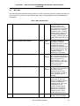
“High Quality”: Transportation equipment (automobiles, trains, ships, etc.); traffic control systems; anti-disaster systems; anticrime systems; safety equipment; and medical equipment not specifically designed for life support.
“Specific”:
Aircraft; aerospace equipment; submersible repeaters; nuclear reactor control systems; medical equipment or
systems for life support (e.g. artificial life support devices or systems), surgical implantations, or healthcare
intervention (e.g. excision, etc.), and any other applications or purposes that pose a direct threat to human life.
You should use the Renesas Electronics products described in this document within the range specified by Renesas Electronics,
especially with respect to the maximum rating, operating supply voltage range, movement power voltage range, heat radiation
characteristics, installation and other product characteristics. Renesas Electronics shall have no liability for malfunctions or
damages arising out of the use of Renesas Electronics products beyond such specified ranges.
Although Renesas Electronics endeavors to improve the quality and reliability of its products, semiconductor products have
specific characteristics such as the occurrence of failure at a certain rate and malfunctions under certain use conditions. Further,
Renesas Electronics products are not subject to radiation resistance design. Please be sure to implement safety measures to
guard them against the possibility of physical injury, and injury or damage caused by fire in the event of the failure of a
Renesas Electronics product, such as safety design for hardware and software including but not limited to redundancy, fire
control and malfunction prevention, appropriate treatment for aging degradation or any other appropriate measures. Because
the evaluation of microcomputer software alone is very difficult, please evaluate the safety of the final products or system
manufactured by you.
Please contact a Renesas Electronics sales office for details as to environmental matters such as the environmental
compatibility of each Renesas Electronics product. Please use Renesas Electronics products in compliance with all applicable
laws and regulations that regulate the inclusion or use of controlled substances, including without limitation, the EU RoHS
Directive. Renesas Electronics assumes no liability for damages or losses occurring as a result of your noncompliance with
applicable laws and regulations.
This document may not be reproduced or duplicated, in any form, in whole or in part, without prior written consent of Renesas
Electronics.
Please contact a Renesas Electronics sales office if you have any questions regarding the information contained in this
document or Renesas Electronics products, or if you have any other inquiries.
(Note 1) “Renesas Electronics” as used in this document means Renesas Electronics Corporation and also includes its majorityowned subsidiaries.
(Note 2) “Renesas Electronics product(s)” means any product developed or manufactured by or for Renesas Electronics.
User’s Manual
8-bit MCU
Release-it! Demo Kit
Document No. U17587EE1V0UM00
Date Published June 2005
© NEC Electronics Corporation 2005
Printed in Germany
[MEMO]
2
UM U17587EE1V0UM00
•
The information in this document is current as of June, 2003. The information is subject to change
without notice. For actual design-in, refer to the latest publications of NEC Electronics data sheets
or data books, etc., for the most up-to-date specifications of NEC Electronics products. Not all
products and/or types are available in every country. Please check with an NEC Electronics sales
representative for availability and additional information.
•
No part of this document may be copied or reproduced in any form or by any means without the prior
written consent of NEC Electronics. NEC Electronics assumes no responsibility for any errors that may
appear in this document.
•
NEC Electronics does not assume any liability for infringement of patents, copyrights or other intellectual
property rights of third parties by or arising from the use of NEC Electronics products listed in this
document or any other liability arising from the use of such products. No license, express, implied or
otherwise, is granted under any patents, copyrights or other intellectual property rights of NEC Electronics
or others.
•
Descriptions of circuits, software and other related information in this document are provided for
illustrative purposes in semiconductor product operation and application examples. The incorporation of
these circuits, software and information in the design of a customer's equipment shall be done under the
full responsibility of the customer. NEC Electronics assumes no responsibility for any losses incurred by
customers or third parties arising from the use of these circuits, software and information.
•
While NEC Electronics endeavors to enhance the quality, reliability and safety of NEC Electronics
products, customers agree and acknowledge that the possibility of defects thereof cannot be eliminated
entirely. To minimize risks of damage to property or injury (including death) to persons arising from
defects in NEC Electronics products, customers must incorporate sufficient safety measures in their
design, such as redundancy, fire-containment and anti-failure features.
•
NEC Electronics products are classified into the following three quality grades: "Standard", "Special" and
"Specific".
The "Specific" quality grade applies only to NEC Electronics products developed based on a customerdesignated "quality assurance program" for a specific application. The recommended applications of an
NEC Electronics product depend on its quality grade, as indicated below. Customers must check the
quality grade of each NEC Electronics product before using it in a particular application.
"Standard": Computers, office equipment, communications equipment, test and measurement
equipment, audio and visual equipment, home electronic appliances, machine tools,
personal electronic equipment and industrial robots.
"Special":
Transportation equipment (automobiles, trains, ships, etc.), traffic control systems,
anti-disaster systems, anti-crime systems, safety equipment and medical equipment
(not specifically designed for life support).
"Specific":
Aircraft, aerospace equipment, submersible repeaters, nuclear reactor control
systems, life support systems and medical equipment for life support, etc.
The quality grade of NEC Electronics products is "Standard" unless otherwise expressly specified in NEC
Electronics data sheets or data books, etc. If customers wish to use NEC Electronics products in applications
not intended by NEC Electronics, they must contact an NEC Electronics sales representative in advance to
determine NEC Electronics' willingness to support a given application.
(Note)
(1) "NEC Electronics" as used in this statement means NEC Electronics Corporation and also includes its majority-owned
subsidiaries.
(2) "NEC Electronics products" means any product developed or manufactured by or for NEC Electronics (as defined
above).
M8E 02. 11-1
UM U17587EE1V0UM00
3
4
UM U17587EE1V0UM00
Overview
Wireless personal area networks (WPANs) are used to convey information over relatively short
distances. Unlike wireless local area networks (WLANs), connections effected via WPANs involve little
or no infrastructure. This feature allows small, power-efficient, inexpensive solutions to be
implemented for a wide range of devices.
Purpose
NEC Electronic, in collaboration with CHIPCON, has developed a new starter kit to allow its customers
to realise new wireless applications. The starter kit, which is based on the NEC 78K0/KF1+, includes
two fully functional modules. Also supplied is a fully optimized library for the IEEE 802.15.4 MAC Layer
Software and applications development and programmer tools.
Reference:
IEEE 802. 15.4: Wireless Medium Access Control (MAC) and Physical Layer (PHY) Specifications for
Low-Rate Wireless Personal Area Networks (LR-WPANs)
UM U17587EE1V0UM00
5
Definitions
For the purposes of this standard, the following terms and definitions apply. Terms not defined in this
clause can be found in the The Authoritative Dictionary of IEEE Standards Terms, Seventh Edition
[B1].
Access control list (ACL)
A table used by a device to determine which devices are authorized
to perform a specific function.
Alternate personal area
network (PAN) coordinator
A coordinator that is capable of replacing the personal area network
(PAN) coordinator, should it leave the network for any reason. A PAN
can have zero or more alternate PAN coordinators.
Association
The service used to establish a device’s membership in a wireless
personal area network (WPAN).
Coordinator
An full-function device (FFD) that is configured to provide
synchronization services through the transmission of beacons. If a
coordinator is the principal controller of a personal area network
(PAN), it is called the PAN coordinator.
Coverage area
The area where two or more IEEE 802.15.4 ™ units can exchange
messages with acceptable quality and performance.
Device
Any entity [reduced-function device (RFD) or full-function device
(FFD)] containing an implementation of the IEEE 802.15.4 medium
access control (MAC) and physical interface to the wireless medium.
Disassociation
The service that removes an existing association.
Frame
The format of aggregated bits from a medium access control (MAC)
sublayer entity that are transmitted together in time.
Full-function device (FFD)
A device capable of operating as a coordinator or device and
implementing the complete protocol set.
Logical channel
One of a variety of channels on a physical link.
Orphaned device
A device that has lost contact with its associated personal area
network (PAN) coordinator.
Personal area network (PAN) A coordinator that is the principal controller of a personal area
network (PAN). An IEEE 802.15.4 network has exactly one PAN
coordinator
coordinator.
Payload data
The contents of a data message that is being transmitted.
Protocol data unit (PDU)
The unit of data exchanged between two peer entities.
Packet
The format of aggregated bits that are transmitted together in time
across the physical medium.
Personal operating space
(POS)
The space about a person or object that is typically about 10 m in all
directions and envelops the person or object whether stationary or in
motion.
Security suite
A group of security operations designed to provide security services
on medium access control (MAC) frames.
6
UM U17587EE1V0UM00
Service data unit (SDU)
Information that is delivered as a unit through a service access point
(SAP).
Transaction
The exchange of related, consecutive frames between two peer
medium access control (MAC) entities, required for a successful
transmission of a MAC command or data frame.
Wireless medium (WM)
The medium used to implement the transfer of protocol data units
(PDUs) between peer physical layer (PHY) entities of a low-rate
wireless personal area network (LR-WPAN).
UM U17587EE1V0UM00
7
Acronyms and abbreviations
ACL
access control list
BE
backoff exponent
BER
bit error rate
BI
beacon interval
BO
beacon order
BPSK
binary phase-shift keying
BSN
beacon sequence number
CAP
contention access period
CCA
clear channel assessment
CFP
contention-free period
CID
cluster identifier
CRC
cyclic redundancy check
CSMA-CA
carrier sense multiple access with collision avoidance
CTR
counter mode
CW
contention window (length)
DSN
data sequence number
ED
energy detection
FCS
frame check sequence
FFD
full-function device
GTS
guaranteed time slot
IFS
interframe space or spacing
LAN
local area network
LPDU LLC
protocol data unit
LR-WPAN
low-rate wireless personal area network
LSB
least significant bit
MAC
medium access control
MCPS MAC
common part sublayer
MCPS-SAP MAC
common part sublayer-service access point
MIC
message integrity code
MLME MAC
sublayer management entity
MLME-SAP MAC
sublayer management entity-service access point
MSB
most significant bit
MSC
message sequence chart
MPDU MAC
protocol data unit
MSDU MAC
service data unit
NB
number of backoff (periods)
PAN
personal area network
PD-SAP PHY
data service access point
PDU
protocol data unit
PER
packet error rate
PIB PAN
information base
PLME
physical layer management entity
8
UM U17587EE1V0UM00
PLME-SAP
physical layer management entity-service access point
POS
personal operating space
PPDU PHY
protocol data unit
PSDU PHY
service data unit
RF
radio frequency
RFD
reduced-function device
RSSI
received signal strength indication
RX
receive or receiver
SAP
service access point
SD
superframe duration
SPDU SSCS
protocol data units
SDU
service data unit
SFD
start-of-frame delimiter
SHR
synchronization header
SO
superframe order
TRX
transceiver
TX
transmit or transmitter
WLAN
wireless local area network
WPAN
wireless personal area network
UM U17587EE1V0UM00
9
Table of Contents
CHAPTER 1
1.1
Network Types .......................................................................................................................................16
1.2
Two physical device types for the lowest system cost ......................................................................18
1.3
MAC and PHY Layers ............................................................................................................................18
1.4
Frame Structure .....................................................................................................................................19
1.5
Modes of operation................................................................................................................................20
1.5.1 Beacon Mode...................................................................................................................................20
1.5.2 Non Beacon Mode ...........................................................................................................................20
1.6
Zigbee Stack...........................................................................................................................................21
CHAPTER 2
LIBRARY INSTALLATION AND USE .........................................................................22
2.1
Hardware requirements.........................................................................................................................22
2.2
Object Library files ................................................................................................................................22
2.3
IAR Systems Embedded Workbench for 78K0/K0S installation ........................................................23
2.4
IAR project setting .................................................................................................................................24
2.5
Library installation.................................................................................................................................25
2.5.1 Linking library to the project .............................................................................................................25
2.5.2 Provide Header files path.................................................................................................................26
2.5.3 Stack and Heap size setting.............................................................................................................27
2.5.4 Byte alignment data .........................................................................................................................28
2.5.5 Add the linker file .............................................................................................................................29
2.5.6 Debugger setting..............................................................................................................................31
2.5.7 Low level hardware initialisation.......................................................................................................31
2.5.7.1 Main clock oscillator ................................................................................................................31
2.5.7.2 Watchdog Timer ......................................................................................................................31
2.5.7.3 IXRAM memory Initialisation....................................................................................................32
2.5.7.4 low_level_init procedure ..........................................................................................................32
2.5.8 Address Allocations..........................................................................................................................32
2.5.8.1 MAC Address ..........................................................................................................................32
2.5.8.2 Attributes and local address setting .........................................................................................33
2.5.8.3 Initialisation of the libraries ......................................................................................................34
2.6
Library Functions...................................................................................................................................35
2.6.1 Functions defined by the libraries ....................................................................................................35
2.6.2 Confirm and Indication functions......................................................................................................36
2.6.3 Data type definitions.........................................................................................................................36
CHAPTER 3
10
INTRODUCTION ..........................................................................................................15
SAMPLE PROJECT INSTALLATION .........................................................................37
3.1
General introduction..............................................................................................................................37
3.2
Project directory ....................................................................................................................................37
3.3
Project use .............................................................................................................................................38
3.4
Library setting ........................................................................................................................................40
3.4.1 Include paths....................................................................................................................................40
3.4.2 Defined symbols ..............................................................................................................................40
3.4.3 Other options ...................................................................................................................................41
3.4.3.1 Load file output ........................................................................................................................41
3.4.3.2 Debugger setting .....................................................................................................................43
UM U17587EE1V0UM00
CHAPTER 4
APPLICATION DESCRIPTIONS AND OPERATIONS................................................45
4.1
LED pattern transmission .....................................................................................................................45
4.2
Serial data transmission .......................................................................................................................45
4.3
Initialisation ............................................................................................................................................45
4.3.1 Device ..............................................................................................................................................46
4.3.2 Coordinator ......................................................................................................................................46
4.4
Run Mode ...............................................................................................................................................46
4.4.1 Run functions ...................................................................................................................................46
4.4.2 Operation Procedure........................................................................................................................49
4.5
Application flowchart ............................................................................................................................50
4.6
Software..................................................................................................................................................52
4.6.1 Low_Level_Init .................................................................................................................................52
4.6.2 Init ....................................................................................................................................................52
4.6.3 Joystick_App....................................................................................................................................52
4.6.4 Control_LEDs...................................................................................................................................52
4.6.5 UART_Transmission ........................................................................................................................52
4.6.6 MAC_SW_78K_Sample...................................................................................................................53
4.6.7 Application_Declaration - header file................................................................................................53
CHAPTER 5
MAC LAYER OVERVIEW ............................................................................................54
5.1
MAC Sublayer.........................................................................................................................................54
5.2
MAC sublayer service specification.....................................................................................................54
5.3
MAC data service ...................................................................................................................................55
5.4
MAC management service ....................................................................................................................55
5.5
MAC Software limitations and Bugs ....................................................................................................56
CHAPTER 6
APPLICATION PROGRAMMING INTERFACE FOR RELEASE-IT PLATFORM .....58
6.1
Introduction ............................................................................................................................................59
6.2
Software Interface..................................................................................................................................59
6.2.1 Request............................................................................................................................................59
6.2.2 Confirm ............................................................................................................................................59
6.2.3 Indication..........................................................................................................................................59
6.2.4 Response.........................................................................................................................................59
6.3
MCPS-SAP ..............................................................................................................................................60
6.3.1 MCPS_DATA.Request.....................................................................................................................60
6.3.2 MCPS-DATA.Confirm ......................................................................................................................60
6.3.3 MCPS_DATA.Indication...................................................................................................................60
6.3.4 MCPS_DATA.Purge.........................................................................................................................61
6.4
MLME-SAP..............................................................................................................................................61
6.4.1 MLME-ASSOCIATE.Request...........................................................................................................61
6.4.2 MLME-ASSOCIATE.Indication.........................................................................................................62
6.4.3 MLME-ASSOCIATE.Response........................................................................................................62
6.4.4 MLME-ASSOCIATE.Confirm ...........................................................................................................62
6.4.5 MLME-DISASSOCIATE.Request.....................................................................................................63
6.4.6 MLME-DISASSOCIATE.Indication...................................................................................................63
6.4.7 MLME-DISASSOCIATE.confirm ......................................................................................................63
6.4.8 MLME-BEACON-NOTIFY.Indication................................................................................................64
6.4.9 MLME-GET-Request........................................................................................................................64
6.4.10 MLME-GTS ......................................................................................................................................64
6.4.11 MLME-ORPHAN.Indication..............................................................................................................64
6.4.12 MLME-ORPHAN.Response .............................................................................................................64
UM U17587EE1V0UM00
11
6.4.13
6.4.14
6.4.15
6.4.16
6.4.17
6.4.18
6.4.19
6.4.20
6.4.21
6.4.22
6.4.23
6.5
MLME-RESET.Request ...................................................................................................................65
MLME-RX-ENABLE.Request...........................................................................................................65
MLME-RX-ENABLE.Confirm............................................................................................................65
MLME-SCAN.Request .....................................................................................................................65
MLME-SCAN.Confirm ......................................................................................................................66
MLME-SET.Request ........................................................................................................................67
MLME-START.Request ...................................................................................................................67
MLME-SYNC.Request .....................................................................................................................68
MLME-SYNC-LOSS.Indication ........................................................................................................68
MLME-POLL.Request ......................................................................................................................68
MLME-POLL.Confirm.......................................................................................................................68
MAC PIB..................................................................................................................................................69
CHAPTER 7
12
APPENDIX: NEC DEBUGGER INSTALLATION AND USE .......................................74
UM U17587EE1V0UM00
List of Figures
Figure 1. Star Topology ..........................................................................................................................16
Figure 2. Peer to Peer Topology ............................................................................................................17
Figure 3. Cluster Tree Topology.............................................................................................................17
Figure 4. IEEE 802.14.5 working model.................................................................................................19
Figure 5. Frame Structure ......................................................................................................................19
Figure 6. Superframe structure with GTSs.............................................................................................20
Figure 7. 2.4 Ghz global ISM band.........................................................................................................20
Figure 8. Zigbee stack ............................................................................................................................21
Figure 9. Libraries...................................................................................................................................23
Figure 10. IAR project structure .............................................................................................................25
Figure 11. Include path project option ....................................................................................................26
Figure 12. Stack size project option .......................................................................................................27
Figure 13. Heap size project option........................................................................................................27
Figure 14. Byte Alignment Option ..........................................................................................................28
Figure 15. Linker file project option ........................................................................................................29
Figure 16. Debugger project option........................................................................................................31
Figure 17. Library initialisation flowchart ................................................................................................34
Figure 18. Sample IAR project directory structure .................................................................................38
Figure 19. Sample project structure .......................................................................................................39
Figure 20. Include path project option ....................................................................................................40
Figure 21. Output project option.............................................................................................................41
Figure 22. FPL GUI window ...................................................................................................................42
Figure 23. Debug output project option ..................................................................................................43
Figure 24. On-Chip-Debugger project option .........................................................................................44
Figure 25. HyperTerminal Port Connection Figure 26. HyperTernimal Port Settings.........................48
Figure 27. HyperTerminal Settings Figure 28. HyperTerminal ASCII Settings...................................48
Figure 29. Sample application flowchart ................................................................................................50
Figure 30. Run mode flowchart ..............................................................................................................51
Figure 31. MAC sublayer model.............................................................................................................54
Figure 32. Communication to a coordinator in a non beacon-enabled network.....................................55
Figure 33. Communication to a coordinator in a beacon-enabled network............................................55
Figure 34. Message sequence for the MAC data sservice ....................................................................60
Figure 35. Port configuration for ID78K0-TK ..........................................................................................74
Figure 36. ID78K0-QB Debug output project option ..............................................................................75
Figure 37. IAR Configure Tools option ...................................................................................................76
Figure 38. ID78KO-TK configuration ......................................................................................................77
UM U17587EE1V0UM00
13
List of Tables
Table 1. Memory map.............................................................................................................................30
Table 2. Joystick Position Table.............................................................................................................47
Table 3. MCPS-SAP primitives ..............................................................................................................55
Table 4. MLME-SAP primitives ..............................................................................................................55
Table 5. NEC 78K0 MAC software limitations/bugs known ...................................................................56
Table 6. MAC PIB attributes ...................................................................................................................69
14
UM U17587EE1V0UM00
CHAPTER 1 INTRODUCTION
The IEEE 802.15.4 wireless networking standard has been developed to allow for the implementation
of Low-Rate Wireless Personal Area Networks (LR-WPAN).
A LR-WPAN is a simple, low-cost communication network that allows wireless connectivity in
applications with limited power and relaxed throughput requirements. The main objectives of an LRWPAN are ease of installation, reliable data transfer, short-range operation, extremely low cost, and a
reasonable battery life, while maintaining a simple and flexible protocol.
Some of the characteristics of an LR-WPAN are:
•
•
•
•
•
•
•
•
•
•
Over-the-air data rates of 250 kb/s, 40 kb/s, and 20 kb/s
Star or peer-to-peer operation
Allocated 16 bit short or 64 bit extended addresses
Allocation of guaranteed time slots (GTSs)
Carrier sense multiple access with collision avoidance (CSMA-CA) channel access
Fully acknowledged protocol for transfer reliability
Low power consumption
Energy detection (ED)
Link quality indication (LQI)
16 channels in the 2450 MHz band, 10 channels in the 915 MHz band, and 1 channel in the 868
MHz band
Two different device types can participate in an LR-WPAN network; a full-function device (FFD) and a
reduced-function device (RFD). The FFD can operate in three modes serving as a personal area
network (PAN) coordinator, a coordinator, or a device. An FFD can talk to RFDs or other FFDs, while
an RFD can talk only to an FFD. An RFD is intended for applications that are extremely simple, such
as a light switch or a passive infrared sensor; they do not have the need to send large amounts of data
and may only associate with a single FFD at a time. Consequently, the RFD can be implemented
using minimal resources and memory capacity.
UM U17587EE1V0UM00
15
CHAPTER 1
1.1
INTRODUCTION
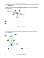
Network Types
There are 2 basic types of network topology available with IEEE 802.15.4, they are Star Topology and
Peer to Peer topology.
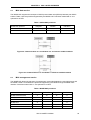
Network
coordinator
Master/slave
Full function device
Communications flow
Reduced function device
Figure 1. Star Topology
In a star network all devices will communicate directly with a central coordinator, this includes both
FFD and RFD devices.
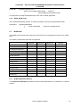
Point to point
Full function device
16
Communications flow
UM U17587EE1V0UM00
CHAPTER 1
INTRODUCTION
Figure 2. Peer to Peer Topology
In a Peer to Peer network devices can communicate directly with each other however this is only
possible if the devices are FFD. It is not possible for an RFD device to communicate directly with
another device, an RFD device can only communicate with a coordinator. In a peer to peer network
you still must have a coordinator.
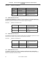
Both network topologies maybe combined to form a Cluster tree network, which will allow for the
building of complex network structures such as Mesh networks etc.
Cluster Tree Example
Clustered stars - for example,
cluster nodes exist between
rooms of a hotel and each room
has a star network for control.
Full function device
Communications flow
Reduced function device
Figure 3. Cluster Tree Topology
UM U17587EE1V0UM00
17
CHAPTER 1
1.2
INTRODUCTION
Two physical device types for the lowest system cost
To allow vendors to supply the lowest possible cost devices the IEEE standard defines two types of
devices: full function devices and reduced function devices.
•
•
Full function device (FFD)
• Can function in any topology
• Capable of being the Network coordinator
• Capable of being a coordinator
• Can talk to any other device
Reduced function device (RFD)
• Limited to star topology
• Cannot become a network coordinator
• Talks only to a network coordinator
• Very simple implementation
An IEEE 802.15.4/ZigBee network requires at least one full function device as a network coordinator,
but endpoint devices may be reduced functionality devices to reduce system cost.
•
•
•
1.3
All devices must have 64 bit IEEE addresses
Short (16 bit) addresses can be allocated to reduce packet size
Addressing modes:
• Network and device identifier (star)
• Source/destination identifier (peer-peer)
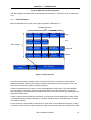
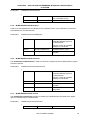
MAC and PHY Layers
The IEEE 802.15.4 standard specifically details the implementation of the PHY (Physical) layer and
the MAC (Media Access Control) layer. The simplified structure of this is shown below.
Upper Layers
IEEE 802.15.4 LLC
IEEE 802.2
LLC, Type I
Software supplied by
NEC Electronics
IEEE 802.15.4 MAC
IEEE 802.15.4
868/915 MHz
PHY
18
IEEE 802.15.4
2400 MHz
PHY
UM U17587EE1V0UM00
CHAPTER 1
INTRODUCTION
Figure 4. IEEE 802.14.5 working model
The SW supplied in the NEC starter kit implements the 2400 Mhz / 2.4 GHz PHY layer and MAC layer
only.
1.4
Frame Structure
Below is illustrated the four basic frame types supported by IEEE 802.15.4
127 Bytes Maximum
2
1
0-20
Frame Sequence Address
Control Number
Info
Frame Sequence
Control Number
Variable
2
Data
Payload
Frame
Check
Frame
Check
Data
Ack
MAC Frames
Synchronisation
Header
Frame Sequence Address Command
Frame
Control Number
Info Type/Payload Check
Command
Frame Sequence Address
Info
Control Number
Beacon
Phy
Header
Beacon
Payload
Frame
Check
MAC Payload
Figure 5. Frame Structure
The data frame provides a payload of up to 102 bytes. The frame is numbered to ensure that all
packets are tracked. A frame-check sequence ensures that packets are received without error. This
frame structure improves reliability in difficult conditions.
Another important structure for 802.15.4 is the acknowledgment (ACK) frame. It provides feedback
from the receiver to the sender confirming that the packet was received without error. The device
takes advantage of specified "quiet time" between frames to send a short packet immediately after the
data-packet transmission.
A MAC command frame provides the mechanism for remote control and configuration of client nodes.
A centralized network manager uses MAC to configure individual clients' command frames no matter
how large the network.
Finally, the beacon frame wakes up client devices, which listen for their address and go back to sleep
if they don't receive it. Beacons are important for mesh and cluster-tree networks to keep all the nodes
UM U17587EE1V0UM00
19
CHAPTER 1
INTRODUCTION
synchronized without requiring those nodes to consume precious battery energy by listening for long
periods of time.
1.5
Modes of operation
There are 2 basic modes of operation for 802.15.4 networks, they are Beacon Mode and Non Beacon
Mode.
1.5.1
Beacon Mode
In Beacon mode a coordinator will transmit a beacon at pre-determined intervals, the intervals can
vary between 15ms and approximately 4 minutes. Devices on the network use the beacons to
synchronise access to the network. In between each beacon there are 16 equal time slots allocated
for message delivery. The channel for access is normally contention based but the coordinator can
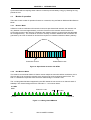
guarantee up to seven channels for devices that require non contention based low latency delivery.
Beacon
Contention Access
Guaranteed Access
Figure 6. Superframe structure with GTSs
1.5.2
Non Beacon Mode
This mode is conventional CSMA-CS Carrier sense multiple access with collision avoidance, this is
where a device can access the network at any time as long as the required channel is free. The
802.15.4 standard incorporates mechanisms for determining if a channel is free.
The 2.4 Ghz global ISM band supported by the NEC starter kit has access to 16 channels each of
256Kbps. The channel assignment from channels 11 – 26 is shown below.
2.4 GHz
PHY
Channels 11-26
2.4 GHz
2.4835 GHz
Figure 7. 2.4 Ghz global ISM band
20
5 MHz
UM U17587EE1V0UM00
CHAPTER 1
1.6
INTRODUCTION
Zigbee Stack
The NEC wireless starter kit fully supports the IEEE 802.15.4 wireless networking standard and
numerous applications can be realised using this, however the kit is ready for the new emerging
ZigBee protocol. The following diagram shows the relationship between IEEE 802.15.4 and ZigBee.
ZigBee Device Object
Security
Service
Provider
Application
Object
Application Support Sub Layer
ZigBee Network Layer
MCPS-
MLMEIEEE 802.15.4 MAC
IEEE 802.15.4 PHY
Figure 8. Zigbee stack
The new ZigBee protocol interfaces directly to the IEEE 802.15.4 MAC layer via the MCPS and MLME
primitives normally called a SAP (Service Access Point). This is clearly defined in the IEEE 802.15.4
standard and it is these access points that are used in the demonstration applications.
The ZigBee protocol adds the additional functionality of network joining and leaving, routing across
multiple networks, security key management and application profiles and support.
UM U17587EE1V0UM00
21
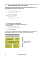
CHAPTER 2 LIBRARY INSTALLATION AND USE
The NEC IEEE 802.15.4 software library consists of three major functional components: MAC sublayer
primitives, PHY layer primitives and Chipcon transceiver device drivers.
MAC_78K0_Lib are C object file libraries for NEC’s 8-bit microcontrollers. They are built using the IAR
Embedded Workbench for NEC 78K0 and 78K0S microcontrollers. These libraries are fully compliant
with the IEEE 802.14.2 standard.
The libraries handle frame transmission and reception, network association and disassociation, and
beacon superframe structures for network time synchronisation (and guaranteed time slot (GTS) and a
mechanism for high-priority communication - not supported yet).
The application layer has to define the network topology, security features and applications. It handles
device discovery and network configuration.
The Libraries offered with the Release-it kit are built for the NEC 78K0148H device. The libraries must
be used with the header files and linker file provided and a target which matches the Release-It
hardware configuration.
These header files can be integrated with user’s application files. The files may be used as reference,
but users are free to make any modifications. However, system definitions such as C structures should
not be changed as they are configured for the MAC and PHY layers.
The following sections deal with how to use these libraries in an IAR Workbench project which is
based on the sample project supplied with the Release-It kit.
2.1
Hardware requirements
•
The minimal hardware requirements for IEEE 802.15.4 networking supported by this library are:
• ROM 20 Kbytes
• RAM 1500 bytes
• Timer 51
• Timer 001
• Timer 011
• CSI port
• INTP0
• General purpose I/O lines (6 maximum)
•
Development tools and software required:
• IAR Embedded Workbench for 78K0/K0S and 78K0 simulator/debugger are required to build
the project and use the libraries.
• FPL FLASH programming software to program the NEC 78K0/KF1+ microcontroller in circuit
is required.
• Full sample project for the NEC 78K0/KF1+ using IAR Systems Embedded Workbench is
included in the Release-It kit.
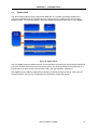
2.2
Object Library files
The IEEE standard defines two types of devices:
•
22
Full function device (FFD)
UM U17587EE1V0UM00
CHAPTER 2
LIBRARY INSTALLATION AND USE
• Reduced function device (RFD)
The libraries provide an interface between the Application/Network layer and the MAC Layer by
providing external primitives. To the primitives are added functions required for a correct use of the
libraries, as MAC_78K0_Init, setattribute, getattribute, resetrxfifo, flushtxfifo, ……
These libraries are provided with three header files that share the required function prototypes,
definitions and variable declarations with the application layer.
Path: Compact Disc\Library Object Files
Figure 9. Libraries
These folders are provided with the Release-It kit:
•
Full function device Library
• Object file: MAC_78KO_FFD_Lib.r26
• Reduced function device Library
• Object file: MAC_78KO_RFD_Lib.r26
• Header files common to the both libraries
• Header file: Data_Types.h
Mac_78KO.h
Function_Prototypes.h
• Linker file common to the both libraries - modified for MAC requirements
• Linker file: DF0148H_V4_ZB.xcl
The libraries are IAR library objet files built with IAR Systems Embedded Workbench. There are two
libraries, one for full-function device (FFD) and one for reduced-function device (RFD)
2.3
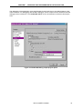
IAR Systems Embedded Workbench for 78K0/K0S installation
The IAR Systems Embedded Workbench for 78K0/K0S required for the starter kit is the time limited
evaluation version. This version EW78K is code size unlimited and offers an Integrated Development
Environment for the NEC 78K0/78K0S microcontrollers. It is available on the on the IAR webpage
http://www.iar.com and the direct link to the webpage to download the evaluation version for
78K0/K0S is:
http://wwwjobb4.iar.se/Download/SW/?item=EW78K-EVAL
For detailed use hints, refer to the data sheet section.
This product contains software components that use a licensing system to prevent illegal use. You
have to registration page and you will receive an e-mail containing license information that is required
during the installation of the evaluation software. Then click on the “Submit Registration and
Download”.
During the installation, the set-up dialogues will guide you through the installation process
UM U17587EE1V0UM00
23
CHAPTER 2
LIBRARY INSTALLATION AND USE
.
.
2.4
IAR project setting
To use a library in an application running on an NEC 78K0 microcontroller, create a new IAR C project
for 78K0 device. Add your own group and application files. Also, add the required library to your
project. Save your project in your application workspace.
Note
24
In your Windows explorer, it is suggested to create a project folder for your application and add
in it a copy of the Libraries, Device_File and Linker_File folders. The libraries folder contains
FFD and RFD object files and the three header files.
UM U17587EE1V0UM00
CHAPTER 2
2.5
LIBRARY INSTALLATION AND USE
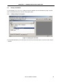
Library installation
To use the MAC object file libraries, library file must be added to the IAR Workbench project, and the
path to the header files has to be set in the project option.
2.5.1
Linking library to the project
Figure 10. IAR project structure
Link the dedicated library to the IAR project as shown by the window above. Use the function Project > Add file.
UM U17587EE1V0UM00
25
CHAPTER 2
2.5.2
LIBRARY INSTALLATION AND USE
Provide Header files path
Figure 11. Include path project option
Provide the header file path in the project option window. For example:
\$PROJ_DIR$\..\..\LIBRARIES\HEADER_FILES\
In this same window, add the path to your own application header files. For example:
\$PROJ_DIR$\..\..\APPLICATION\INCLUDE\
\$PROJ_DIR$\ is currently the directory where is save the application project.
26
UM U17587EE1V0UM00
CHAPTER 2
2.5.3
LIBRARY INSTALLATION AND USE
Stack and Heap size setting
Make sure the stack size is at least ox 0x180 byte to match the library requirement and the heap size
is 0. The linker file define a stack at most of 0x1FF bytes and a heap of 0 byte.
Figure 12. Stack size project option
Figure 13. Heap size project option
UM U17587EE1V0UM00
27
CHAPTER 2
2.5.4
LIBRARY INSTALLATION AND USE
Byte alignment data
The libraries required the setting of the byte alignment data at the time of linking for correct use of the
C structures. In the window Project Option / C Compiler / Code, select the Byte Alignment Data option.
Figure 14. Byte Alignment Option
28
UM U17587EE1V0UM00
CHAPTER 2
2.5.5
LIBRARY INSTALLATION AND USE
Add the linker file
Set the correct linker file in the project option window. The linker file to use is provided with the sample
project. It is a specified file called DF0148H_V4_ZB.XCL.
It is a specific file for using with the libraries. Some modifications have been done to match the MAC
stack requirement, as new memory segment definitions or memory locations. Therefore, do not use a
standard linker file with these libraries.
Figure 15. Linker file project option
UM U17587EE1V0UM00
29
CHAPTER 2
LIBRARY INSTALLATION AND USE
Memory map
The above linker file is specified for the Release-It kit. The MACADDRESS, heap and stack segments
are defined by this file.
Table 1. Memory map
SEGMENT
START ADDRESS
END ADDRESS
SIZE
INTVEC (ABS)
0000
003F
40
CLTVEC
0040
007D
3E
OPTBYTE
0080
0081
2
SECUID
0084
008E
B
MACADDRESS
0190
019F
10
FCODE
0800
0FFF
800
RCODE
01A0
05BE
41F
CODE
05BF
6DE3
6825
NEAR_ID
6DE4
6DE7
4
SADDR_ID
DIFUNCT
CONST
6DE8
0
SWITCH
6DE8
6F22
13B
VERSION
EFFB
EFFF
4
IXRAM
F400
F7B9
3BA
BUFRAM
FA00
FA1F
1F
HEAP
FB00
CSTACK
FB00
FC7F
180
NEAR_I
FC80
FC83
4
NEAR_Z
FC84
FE43
1C0
0
NEAR_N
SADDR_I
FED0
0
SADDR_Z
FED0
FED7
8
SADDR_A (ABS)
FF00
FF18
19
NEAR_A (ABS)
FF20
FFFB
DC
FFD library + NEC
Sample
28 057 bytes of CODE memory (+ 18 absolute )
WRKSEG
RFD library + NEC
Sample
30
1 798 bytes of DATA memory (+ 62 absolute )
19 340 bytes of CODE memory (+ 18 absolute )
1 793 bytes of DATA memory (+ 62 absolute )
UM U17587EE1V0UM00
CHAPTER 2
2.5.6
LIBRARY INSTALLATION AND USE
Debugger setting
To debug the application, make sure to set the workbench according to the device used. The
appropriate device file for Release-It is io78f0148h.ddf. It is the standard file provided with the IAR
Embedded Workbench.
A copy of this file is provided in the directory Device_File supplied with the Relesed-It kit.
Figure 16. Debugger project option
2.5.7
Low level hardware initialisation
This following part deals with the 78K0 micro initialisation that must be done for library use. It could be
placed at the start of the main function or be the task of a Low_Level_Init routine.
2.5.7.1 Main clock oscillator
The application has to be set to run with a 16MHz main oscillator to match the MAV library
requirements.
2.5.7.2 Watchdog Timer
The watchdog timer has to be handled by the application layer and be set in order to allow the MAC
stack to manage the wireless transmission. The MAC stack requires a watchdog timeout of at least 1s
to run without issue. For application development it is easier to disable the watchdog.
UM U17587EE1V0UM00
31
CHAPTER 2
LIBRARY INSTALLATION AND USE
2.5.7.3 IXRAM memory Initialisation
The IXRAM memory segment has to be initialised. This memory area is not initialised by the C start-up
and should be done in the low level initialisation.
2.5.7.4 low_level_init procedure
The sample program for the Release-It kit does not use the standard Low_Level_Init library routine
and defines its own, to do the above task. Creating a function with the prototype:
int __low_level_init (void)
allows the compiler to replace the function with the user supplied function.
We suggest adding a low_level_init procedure to your project as it has done for the Release-It sample
program.
For further details how to develop this procedure, refer to the sample project and source code supplied
with the Release-It kit.
2.5.8
Address Allocations
The IEEE 802.14.5 standard specifies the PHYsical (PHY) and Media Access Control (MAC) layer.
The standard employs 64-bit IEEE address and 16-bit short address to support theoretically more than
65,000 nodes per networks
The application has to define the network and security. It handles device discovery, network
configuration and address definition.
2.5.8.1 MAC Address
All devices operating on a network of either topology shall have unique 64 bit extended address. This
address can be used for direct communication within the PAN, or it can be exchanged for a short
address allocated by the PAN coordinator when the device associates.
These addresses have to be communicated to the MAC layer through the use of extern function
definitions.
The 64-bit IEEE address has to be defined as a variable declaration in the dedicated flash area
“MACADDRESS” (16 Bytes) setting in the linker file.
This definition should be part of the application variable declarations.
Define the unique 64 bit extended address as it is suggested by the following lines (in this case add =
0x0000004722958919) using the MACADDRESS memory segment:
// Set the physical node address
#pragma constseg=MACADDRESS
__root const QWORD macaddress1 = {0x22958919,0x00000047};
__root const QWORD macaddress2 = {0x22958920,0x00000047};
#pragma constseg=default
The libraries require this extended address definition. In the library’s header file MAC_78K0.h, it is
defined an external QWORD. To transmit the address value, use the following declaration:
// Extended address, must be set by higher layer
extern __saddr QWORD aExtendedAddress;
This variable has to be set in the main function by calling the library function halReadAddress.
32
UM U17587EE1V0UM00
CHAPTER 2
LIBRARY INSTALLATION AND USE
// read MAC address from FLASH and write in RAM variable
ptrTemp = (BYTE*) &aExtendedAddress.ldword;
halReadAddress(ptrTemp, isCoordinator);
The second parameter is a boolean. True allows it to read the first MAC address, and false allows it to
read the second one. The option to provide two extended address was developed for the Release-It
sample program.
For further information and details on how to set the network addresses, refer to the sample project
and source code supplied with the Release-It kit.
2.5.8.2 Attributes and local address setting
Before using the libraries, the following attributes and address definition have to be set by the
application layer.
Local address definition:
PanId
DestPanId
NodeAdd.Short
SecuMode
DestinationAdd.Short
= PANID;
= DEST_PANID;
= DEVICE_SHORT;
= 0x00; No security feature is supported by the libraries
= DEST_SHORT;
Minimum PIB (PAN Information Base) attributes that have to be set:
MAC_SHORT_ADDRESS
MAC_RX_ON_WHEN_IDLE
MAC_ASSOCIATION_PERMIT
MAC_PAN_ID
MAC_SECURITY_MODE
MAC_BEACON_ORDER
MAC_SUPERFRAME_ORDER
The attributes are set and can be read using the following library functions:
// Update PIB attributes
mlmeSetRequest(Attribute, Pointer on data)
// Check PIB attributes
retval = mlmeGetRequest(Attribute, Pointer on test data)
For further details how to set the PIBs, refer to the sample project and application code supplied with
the Release-It kit.
UM U17587EE1V0UM00
33
CHAPTER 2
LIBRARY INSTALLATION AND USE
2.5.8.3 Initialisation of the libraries
The recommended initialisation of the libraries is shown by the following flowchart:
Reset
Wait for main oscillator to stabilise
Set the speed of the main clock to 16 Mhz
Low level
hardware
initialisation
Initialisation of the IXRAM
Set the watchdog timer
Initialisation of the MAC stack library
Call the library’s function Mac_78K0_init();
Setup development board peripherals
Read MAC address from FLASH and write in
RAM variable
Reset the MAC layer, Call the library’s function
mlmeResetRequest
MAC Library
initialisation
Modify PIB attributes
Flush the TX FIFO and Reset the Rx state
machine and variable, call library’s function
Flush_TX_RX_Fifo
Confirm test, Enable the receiver, Call the
library function mlmeRxEnableRequest
Figure 17. Library initialisation flowchart
34
UM U17587EE1V0UM00
CHAPTER 2
2.6
LIBRARY INSTALLATION AND USE
Library Functions
The interface between the Application/Network Layer (NWK) and the MAC Logical Management Entity
Layer (MLME) is based on service primitives passed from one layer to the other using the libraries.
2.6.1
Functions defined by the libraries
For more detail, refer to the Function_Prototypes header file and to the IEEE 802.14.5 standard.
void Mac_78K0_init();
void Flush_TX_RX_Fifo();
// Initialise the library for the 78K0 Release-It kit*
// Flush chipcon’s FIFO for reset*
void halWait(UINT16 timeout);
void halWriteAddress(BYTE *pData);
void halWriteAddress(BYTE *pData);
void mcpsDataRequest(BYTE addrModes, WORD srcPanId, ADDRESS *pSrcAddr, WORD
destPanId, ADDRESS *pDestAddr, UINT8 msduLength, BYTE *pMsdu, BYTE msduHandle, BYTE
txOptions);
void mcpsDataConfirm(MAC_ENUM status, BYTE msduHandle);
void mcpsDataIndication(MCPS_DATA_INDICATION *pMDI);
MAC_ENUM mcpsPurgeRequest(BYTE msduHandle);
//---------------------------------------------------------------------------------------------------------// MLME prototypes
//---------------------------------------------------------------------------------------------------------void mlmeAssociateRequest(UINT8 logicalChannel, BYTE coordAddrMode, WORD coordPANId,
ADDRESS *pCoordAddress, BYTE capabilityInformation, BOOL securityEnable);
void mlmeAssociateIndication(ADDRESS deviceAddress, BYTE capabilityInformation, BOOL
securityUse, UINT8 aclEntry);
void mlmeAssociateResponse(ADDRESS *deviceAddress, WORD assocShortAddress,
MAC_ENUM status, BOOL securityEnable);
void mlmeAssociateConfirm(WORD AssocShortAddress, MAC_ENUM status);
void mlmeBeaconNotifyIndication(MLME_BEACON_NOTIFY_INDICATION *pMBNI);
void mlmeCommStatusIndication(WORD panId, BYTE srcAddrMode, ADDRESS *pSrcAddr, BYTE
dstAddrMode, ADDRESS *pDstAddr, MAC_ENUM status);
void mlmeDisassociateRequest(QWORD *pDeviceAddress, BYTE disassociateReason, BOOL
securityEnable);
void mlmeDisassociateIndication(QWORD deviceAddress, BYTE disassociateReason, BOOL
securityUse, UINT8 aclEntry);
void mlmeDisassociateConfirm(MAC_ENUM status);
MAC_ENUM mlmeGetRequest(MAC_PIB_ATTR pibAttribute, void *pPibAttributeValue);
void mlmeOrphanIndication(QWORD orphanAddress, BOOL securityUse, UINT8 aclEntry);
void mlmeOrphanResponse(QWORD orphanAddress, WORD shortAddress, BOOL
associatedMember, BOOL securityEnable);
void mlmePollRequest(BYTE coordAddrMode, WORD coordPANId, ADDRESS *coordAddress,
BOOL securityEnable);
void mlmePollConfirm(MAC_ENUM status);
MAC_ENUM mlmeResetRequest(BOOL setDefaultPIB);
void mlmeRxEnableRequest(BOOL deferPermit, UINT32 rxOnTime, UINT32 rxOnDuration);
void mlmeRxEnableConfirm(MAC_ENUM status);
MAC_ENUM mlmeScanRequest(BYTE scanType, DWORD scanChannels, UINT8 scanDuration,
MAC_SCAN_RESULT *pScanResult);
MAC_ENUM mlmeSetRequest(MAC_PIB_ATTR pibAttribute, void *pPibAttributeValue);
MAC_ENUM mlmeStartRequest(WORD panId, UINT8 logicalChannel, UINT8 beaconOrder, UINT8
superframeOrder, BOOL panCoordinator, BOOL batteryLifeExtension, BOOL coordRealignment,
BOOL securityEnable);
void mlmeSyncRequest(UINT8 logicalChannel, BOOL trackBeacon);
void mlmeSyncLossIndication(MAC_ENUM lossReason);
UM U17587EE1V0UM00
35
CHAPTER 2
LIBRARY INSTALLATION AND USE
//---------------------------------------------------------------------------------------------------------void mpmSetRequest(BYTE mode);
void mpmSetConfirm(BYTE status);
BYTE mpmGetState(void);
2.6.2
Confirm and Indication functions
Confirm and indication primitives are generated by the library’s MLMEs and issued to the higher
application layer to confirm or indicate a MAC service primitive.
These functions are used to return information about the transaction and allow the MAC layer to
communicate with the upper layer.
void mlmeAssociateIndication(ADDRESS deviceAddress, BYTE capabilityInformation, BOOL
securityUse, UINT8 aclEntry) {}
void mcpsDataIndication(MCPS_DATA_INDICATION *pMDI){}
void mlmeRxEnableConfirm(MAC_ENUM status){}
void mlmeBeaconNotifyIndication(MLME_BEACON_NOTIFY_INDICATION *pMBNI) {}
void mlmeCommStatusIndication(WORD panId, BYTE srcAddrMode, ADDRESS *pSrcAddr, BYTE
dstAddrMode, ADDRESS *pDstAddr, BYTE status) {}
void mlmeDisassociateIndication(QWORD deviceAddress, BYTE disassociateReason, BOOL
securityUse, BOOL aclEntry) {}
void mlmeDisassociateConfirm(MAC_ENUM status) {}
void mlmeOrphanIndication(QWORD orphanAddress, BOOL securityUse, BOOL aclEntry) {}
void mlmePollConfirm(MAC_ENUM status) {}
void mlmeRxEnableConfirm(MAC_ENUM status) {}
void mlmeSyncLossIndication(MAC_ENUM lossReason) {}
void mpmSetConfirm(BYTE status) {}
void mcpsDataIndication(MCPS_DATA_INDICATION *pMDI){}
void mlmeAssociateIndication(ADDRESS deviceAddress, BYTE capabilityInformation, BOOL
securityUse, UINT8 aclEntry){}
void mlmeAssociateConfirm(WORD assocShortAddress, MAC_ENUM status){}
void mcpsDataConfirm(MAC_ENUM status, BYTE msduHandle){}
void mlmeDisassociateConfirm(MAC_ENUM status) {}
void mlmeDisassociateIndication(QWORD deviceAddress, BYTE disassociateReason, BOOL
securityUse, BOOL aclEntry) { }
2.6.3
Data type definitions
All the data type definitions external to the application layer and used in the above functions are
include in the MAC_78K0.h header file. To have access to all functions specified in the library and all
the data types used in it, all the header files used to build the libraries are required. These files are the
property of NEC and can be provided only with specified agreement with NEC Electronics.
36
UM U17587EE1V0UM00
CHAPTER 3 SAMPLE PROJECT INSTALLATION
3.1
General introduction
The sample project combines a simple application with the MAC Layer using the IEEE 802.15.4
libraries.
The application provides interaction with users on the Release–it wireless evaluation boards. There
are two boards in the kit and on power up each board can be connected to the network.
By the manipulation of the hardware, LED patterns can be generated on the board in use. This
provides a visual representation of the hardware selection. Once a pattern for the LEDs has been
selected the board can then transmit this pattern to the other board in the network. This will
synchronise the two boards and they will both display the same pattern, until another pattern is
selected and transmitted from either board.
By the use of a HyperTerminal as graphic user interface, this application also allow to transmit string of
ASCII to the other board in the network, also linking to an hyper terminal window. In this application
the packets send are communicating the ASCII string between each evaluation board.
This shows the ability of the boards to communicate any data with each other via the IEEE 802.15.4
protocol. In this application the packets sent are communicating the LED pattern or ASCII string
between each evaluation board. However, this communication could be any information the user
requires to control the hardware, send data, or request information.
3.2
Project directory
The main directory contains the sub-folder for the project files for the IAR Systems Embedded
Workbench 78K0/K0S, and also the following sub-folders:
UM U17587EE1V0UM00
37
CHAPTER 3
SAMPLE PROJECT INSTALLATION
Main directory
Application folder: Contains the source code
of the C and H files of demo application
Device File (ddf)
IAR_Projects folder: Contains the projects
files for the IAR Systems Embedded
Workbench 78K0/K0S.
It contains the IAR workspace and two subfolders for two projects, FFD and RFD.
Both projects are based on the same
application but use the appropriate library.
Libraries folder: Contains the library object
files for FFD and RFD, and the header files
required for the library use
Linker_File folder: Contains the linker file
Low_Level_Init folder: Contains the low level
init C source code
Figure 18. Sample IAR project directory structure
All the application source C files are located in the directory MAC_78K0_Sample\Application\
DemoSample\Source and the application header files in the directory MAC_78K0_Sample\
Application\DemoSample\Include
The library object files for FFD and RFD are respectively located in:
MAC_78K0_Sample\Libraries\FFD and MAC_78K0_Sample\Libraries\RFD
The library header files are located in the directory:
\MAC_78K0_Sample\Libraries\Header_File
The libraries use the modified DF0148H_V4_ZB.xcl linker file which is located in the directory:
MAC_78K0_Sample\Linker_File
The simulator target uses the io78f0148h.ddf device description file which is located in the directory:
MAC_78K0_Sample\DEVICE_FILE\ddf
3.3
Project use
The IAR Systems Embedded Workbench, must be installed on your PC. For detailed installation hints,
refer to the documentation of the corresponding products.
To open a project, you can start the IAR Systems Embedded Workbench and open the
NEC_MAC_SW_Workspace.eww workspace or directly launch it by double clicking on the eww file.
38
UM U17587EE1V0UM00
CHAPTER 3
SAMPLE PROJECT INSTALLATION
Figure 19. Sample project structure
Two projects are defined in this workspace: MAC_78K0_FFD_PROJ and MAC_78K0_RFD_PROJ.
The difference in these projects is in the library used.
UM U17587EE1V0UM00
39
CHAPTER 3
3.4
Library setting
3.4.1
Include paths
SAMPLE PROJECT INSTALLATION
The library is added to the project in the same way as any other file, and the path of the library’s
header file is set in the project option C Compiler -> Preprocessor.
Figure 20. Include path project option
3.4.2
Defined symbols
Both projects require include paths for the application and library’s header files. The add of defined
symbols is required by the application only.
MAC_OPT_FFD: defines symbols only compliant with the FFD library. This allows call to any MAC
primitive and have all the features of a full-function device.
An application project based on this sample which uses the FFD Library without this defined symbol
will produce code for a reduced-function device, providing the same result as a project using the RFD
library.
An application project based on this sample which uses the RFD Library must not use the defined
symbol MAC_OPT_FFD, which allows the application code to call to MAC primitives only available
with the FFD library as the primitive mlmeStartRequest().
The RFD library could be used for a device node project which will never need to set its own network.
This allows reduction in the size of the MAC stack code.
40
UM U17587EE1V0UM00
CHAPTER 3
SAMPLE PROJECT INSTALLATION
An application project based on this sample which uses the RFD library could require the defined
symbol BEACON_NETWORK which allows to perform a passive scan. This distinction is required
because a reduced function device could only perform a passive scan, used to locate all coordinators
transmitting beacon frames within the POS of the scanning device; but the passive scan is a receiveonly operation. Therefore, on a Non Beacon Enabled Network, a passive scan does not allow to locate
coordinator. So an association process should be automatically performed on the designated channel.
3.4.3
Other options
3.4.3.1 Load file output
The stack size is set to 0x180 byte, the heap size to 0x00, and the DF0148H_V4_ZB.xcl linker file is
set in the Linker\Config\Linker command file. The built output is a hexadecimal file of the Intel
extended format that can be flashed into the Release-It board using the FPL writer software V1.10.
Figure 21. Output project option
UM U17587EE1V0UM00
41
CHAPTER 3
SAMPLE PROJECT INSTALLATION
The FPL FLASH Programming software is Windows based software provided with the Release-It kit in
the directory \FPL\ of the CDROM. It allows the user to select and download application programs to
NEC microcontroller for evaluation purposes.
Figure 22. FPL GUI window
Note
42
Refer to the FPL installation document and user manual to flash Intel extended files into an
NEC microcontroller. Port, Speed, Frequency, Multiply rate, Parameter file and Load file
have to be set before programming.
For further information, please refer to the FPL Flash Programming user’s manual.
UM U17587EE1V0UM00
CHAPTER 3
SAMPLE PROJECT INSTALLATION
3.4.3.2 Debugger setting
The debugging of the application using the Release-It board uses the on-chip debug feature of the
78F0148 device. For debugging, set the output format to C-SPY and the debugger driver to Minicube.
The io78f0148h.ddf file must to be selected in the device description area.
For debugging using the NEC Debugger ID78K0-QB, the output file has to be a xcoff78K. for further
information about how to set and use the NEC Debugger, please refer to the relative appendix at the
end of this document and to the software user’s manual.
The use of the on-chip debug feature with the Release-It board, required IAR C-SPY debugger /
simulator. For further information, refer to the IAR Systems Embedded Workbench for 78K0/78K0S user’s
manual.
Figure 23. Debug output project option
UM U17587EE1V0UM00
43
CHAPTER 3
SAMPLE PROJECT INSTALLATION
Figure 24. On-Chip-Debugger project option
44
UM U17587EE1V0UM00
CHAPTER 4 APPLICATION DESCRIPTIONS AND OPERATIONS
LED pattern transmission
4.1
Provided as peripheral hardware on each of the boards is a joystick, which is available to the user for
application purposes. This hardware, is interfaced to the board via standard I/O pins and with the
creation of application software, it is possible to monitor the inputs on these pins and therefore
determine the position of the joystick each time it is moved.
With this information this application then utilises the LED provided on the board (LED 1, 2, 3) to
display a on/off pattern, representing the joystick position. Each joystick position produces a different
LED pattern
Once a pattern for the LEDs has been selected, the board can then transmit this pattern to the other
board in the network. This will synchronise the two boards and they will both display the same pattern,
until another pattern is selected and transmitted from either board. In this application the packets sent
are communicating the LED pattern between each evaluation board.
Serial data transmission
4.2
This application uses a Hyperterminal window as a user interface. This allows entry of any string of
ASCII and to transmit it to the other board in the network, also linking to a Hyperterminal window. The
host PC is connected to the Release-It board using an USB cable. Each ASCII character is directly
transmitted and stored in a memory buffer of 28 bytes. The carriage return code denotes the end of
the string and requests the system start a transmission task. This will allow creation of a chat star
network where endpoint devices could talk with the network coordinator. In this application the packets
send are communicating the ASCII string between each evaluation board.
Initialisation
4.3
Note
The switches available on these boards provide different functionalities at different stages
of the application.
On power up the evaluation boards are initialised and then wait for user input. The Power LED will
light up showing that the board has power and the system is running. No other indicators are
provided.
Note
Depend on the battery jump setting, Release-It kit could be powered by USB interface, no
separate power supply is needed, or by 9V Battery The USB interface provides the
Release-It board with 5V supply voltage.
At this stage the switches provide the following functions:
•
•
•
SW6
SW2
SW3
RESET
Selects Device (on the Network)
Selects Coordinator (on the Network)
UM U17587EE1V0UM00
45
CHAPTER 4
4.3.1
APPLICATION DESCRIPTIONS AND OPERATIONS
Device
When switch 2 (SW2) is pressed, Device type network association will be selected for this board. This
means that the board will operate as the slave within the network, able to only to transmit and receive
data to/from the coordinator.
When set as a device, the board will start to scan for the coordinator on the local network until one is
found. The scan process is indicated by LED 3 = ON. When a coordinator is found the following
occurs:
• An association request is made by the device to the coordinator
• Acknowledgement is then received back from the coordinator
• The device will then send a Data Request back and
• The coordinator then acknowledges and provides an association response
An Association response contains the association status. This should contain a success value and
with this a network short address which is a16-bit length. Once this is completed LED 3 = OFF and
LED 2 = ON, indicating a correct status and network address. The program will now enter Run Mode
ready for the main application to be used.
4.3.2
Coordinator
When switch 3 (SW3) is pressed, Coordinator type network association will be selected for this board.
This means that the board will operate as the manager within the network, able to control and
supervise the network communications.
When set as a Coordinator, the following occurs:
• A start request is called to create a new network, by providing network configuration
• A “no beacon” network is then established
• If this is successful then the LED’s on the board will indicate this with LED 1, 2, 3, = ON
The coordinator can now respond to any scan requests made by any node. The settings and PAN
description will then be transmitted. The program will now enter Run Mode ready for the main
application to be used.
Run Mode
4.4
Once the network association types are chosen on each board, the application enters into standard
Run Mode. They are then ready to receive input from the user.
4.4.1
Run functions
At this stage the switches provide the following functions:
•
•
•
46
SW6
SW2
SW3
RESET
Selects to Disassociate from the Network
Selects to Transmit data to the other board
UM U17587EE1V0UM00
CHAPTER 4
APPLICATION DESCRIPTIONS AND OPERATIONS
At this stage the Joystick is now active and provides the following functions:
Table 2. Joystick Position Table
Position
Direction
Binary Output
Up
P40 P41 P42
0
0
0
Down
P40 P41 P42
0
1
0
Left
P40 P41 P42
0
1
1
Right
P40 P41 P42
1
1
0
Centre
Push
LED Pattern
P40 P41 P42
1
1
1
At this stage the UART port is now initialised and active. This function allowed to a Host PC terminal
software for communication with Demo Network.
The UART port is connected to a FTDI USB-to-RS232 Interface Chip.
The Release-It board is connected to the host system via USB interface cable.
The USB host interface enables communication to the Release-It board. The USB UART chip FT232
allows application software to access the USB device in the same way as it would access a standard
RS232 interface. The FTDI's Virtual COM Port ( VCP ) driver appears to the windows system as an
extra Com Port, in addition to any existing hardware Com Ports.
Chat transmission through the UART
HyperTerminal, or other available PC-based communications programs, can be used, communicating
through FTDI VCP drivers with virtual COM port.
The both nodes have to be connected to a host PC to enjoy this application.
HyperTerminal setting
The protocol used for the chat application is a standard RS232 protocol, 38400 bits per second, 8 bits
of data, no parity, 1 bit stop and no flow control.
The completed HyperTerminal setting required is showed in the different figures below.
UM U17587EE1V0UM00
47
CHAPTER 4
APPLICATION DESCRIPTIONS AND OPERATIONS
Figure 25. HyperTerminal Port Connection
Figure 26. HyperTernimal Port Settings
Figure 27. HyperTerminal Settings
Figure 28. HyperTerminal ASCII Settings
Each ASCII character is directly transmitted to the Release-It board and handle by the UART6
received interup routine. This ISR stored it in a buffer table of 28 bytes. The carriage return code
denotes the end of the string and requests the system start a transmission task. In this application the
packets send are communicating the ASCII string between each evaluation board.
The reception of a chat packet managed by the library, will be transmit through the UART to the
HyperTerminal communications programs
Note
48
For an Associated Device, transmission is fixed to transmit only to it’s coordinator. For the
Network Coordinator, the transmission is open to all devices. Therefore, to select a specific
device to transmit data, the device first need to transmit the first packet to the coordinator,
allowing the coordinator to opt for the correct destination address from it’s list of devices on
the network.
UM U17587EE1V0UM00
CHAPTER 4
4.4.2
APPLICATION DESCRIPTIONS AND OPERATIONS
Operation Procedure
The following steps describe the method of utilising this application. Please use these for setup,
initialisation and operation of the boards for this application.
(1)
If attempting to use the chat transmission, set up host-PC communications programs
(2)
Connect each of the board to their battery and power up the system
(3)
If attempting to use the chat transmission, connect each of the board to a host-PC
communications programs via USB cable.
(4)
To ensure operation is running correctly press the reset button (SW6)
(5)
Choose a board to be used as the Coordinator and select Coordinator association by
pressing SW2. All LED’s should then turn on once initialisation is completed
(6)
The other board needs to then operate as the device. Press SW3 to select Device
Association. The LED 3 will turn on for a short period, and then turn off while LED 2
turns on.
(7)
The boards are now in Run Mode and the application is ready to use.
(8)
On the board with device association, push the joystick in any direction. The LED
pattern will appear as shown in Table 2.3
(9)
Then to transmit this to the other board (Coordinator), press SW3.
(10)
The packet is then transmitted to the coordinator board and the same LED pattern will
appear on this board. Both boards now have the same LED pattern.
(11)
Now on the Coordinator board, select a LED pattern as done previously by using the
joystick.
(12)
Press SW3 to transmit this back to the Devices board. Both boards again have the
same pattern.
(13)
Repeat the operation to use this application
(14)
If chat transmission is set, type out sentences into the PC communications program
window and send it using the carriage return key.
(15)
To disassociate use SW2 on the Device board. This will disassociate the device from
the coordinator for a short period. LED 3 will turn on, the board will re-associate with
a new short address and LED will turn off, while LED 2 turns on.
UM U17587EE1V0UM00
49
CHAPTER 4
4.5
APPLICATION DESCRIPTIONS AND OPERATIONS
Application flowchart
Low level initialisation
Mac layer initialisation
Application peripheral
initialisation
Network role
Uart initialisation
Toggle LEDs
Association process
If is coordinator, start to
set a new network
If is device, scan for a
coordinator and start an
association process
Update the PIB
Running
Loop
Wait for an
event flag
Figure 29. Sample application flowchart
50
UM U17587EE1V0UM00
CHAPTER 4
APPLICATION DESCRIPTIONS AND OPERATIONS
MAC Layer and
Application Initialisation
Running loop
Wait for the event flag
Receipt ASCII string
Receipt flag
Store the received
Copy the received
string into a data
payload table
If LED pattern, toggle
LEDs and display it
Transmit the packet
If ASCII string packet,
transmit it through
UART
Joystick flag
Disassociation flag
Toggle LEDs and
update the LED pattern
If is device, send
disassociation request
Transmit packet flag
Start an association
process – goto.
Transmit the last data
packet, which is LED
pattern or ASCII string
depend on the previous
event
Figure 30. Run mode flowchart
UM U17587EE1V0UM00
51
CHAPTER 4
APPLICATION DESCRIPTIONS AND OPERATIONS
Software
4.6
For detailed information about the software installation please refer to the source code on the
installation CD. The following software is to provide an indication of where the functions are
positioned.
Notes
−
−
−
−
−
−
−
The Low level initialisation (Low level init) is required (main oscillator setting, variables
initialisation, watchdog setting), otherwise these have to be a part of the customer
application.
Watchdog management has to be handled by the application (or disabled)
Provide the MAC extended address to the MAC library as it is describe in 4.6.7Address Allocations
The NEC sample application provides a network management example, association,
disassociation, address allocations.
The definition of these addresses (PanID, short coord. address, associated devices
address, etc) are parts of the applications and have to be transmitted to the MAC layer
(see modify attribute in the application code)
2 Libraries are provided with 3 header files. The libraries can not be used without the
header files.
For correct use of libraries refer to the application code or to the section 3-Application
Programming Interface or the IEEE802.15.4 standard.
The application code consists of six C files and one header file.
4.6.1
Low_Level_Init
This function deals with the low level hardware initialisation. It manages the main clock, the watchdog
timer and the IXRAM initialisation.
4.6.2
Init
Application hardware peripherals initialisation. In this file, are initialised the port 7 for joystick and
switch input, port 4 for the LEDs output, and the timer H0 for adding delay and timer 50 for periodic
joystick reading.
4.6.3
Joystick_App
Timer 50 interrupt service routine, return the joystick position. Used by the application to display the
LED pattern.
4.6.4
Control_LEDs
Is defined in this file an idle loop using timer H0 to add delay and LED rolling functions as the function
that switches the LEDs regarding the joystick position.
4.6.5
UART_Transmission
In this file are defined functions regarding the serial interface UART6. These function are;
•
•
•
•
52
Initialisation of the serial interface UART6
Enable operations through the UART6 interface
Disable operations through the UART6 interface
Transmit character through the UART6 interface
UM U17587EE1V0UM00
CHAPTER 4
•
•
APPLICATION DESCRIPTIONS AND OPERATIONS
Transmission completion interrupt service routine
Reception interrupt service routine
4.6.6
MAC_SW_78K_Sample
Main application which manage MAC layer and hardware peripheral initialisation, network setting and
the running mode process.
In this file is also defined the Confirm and indication primitives that allow the application layer to
confirm or indicate a MAC service primitive.
4.6.7
Application_Declaration - header file
This file contains definition declarations, global variable declarations and function prototypes
declarations for the application layer.
UM U17587EE1V0UM00
53
CHAPTER 5 MAC LAYER OVERVIEW
This document includes documentation on the NEC library IEEE 802.15.4 Mac Software and on the
library use. This document does not include functional descriptions of the behaviour of the MAC
sublayer primitives. To take full advantage of the features within the NEC MAC Software, it is
necessary to understand the IEE standard 802.15.4 specifications.
MAC Sublayer
5.1
The MAC (Medium Access Control) sublayer handles all access to the physical radio channel and is
responsible for the following tasks:
−
−
−
−
−
−
−
Generating network beacons if the device is a coordinator.
Synchronising to the beacons.
Supporting PAN association and disassociation.
Supporting device security.
Employing the CSMA-CA mechanism for channel access.
Handling and maintaining the GTS mechanism.
Providing a reliable link between two peer MAC entities.
MAC sublayer service specification
5.2
The MAC sublayer provides an interface between the SSCS and the PHY. The MAC sublayer
conceptually includes a management entity called the MLME. This entity provides the service
interfaces through which layer management functions may be invoked. The MLME is also responsible
for maintaining a database of managed objects pertaining to the MAC sublayer. This database is
referred to as the MAC sublayer PIB.
MCPS-SAP
MLME-SAP
MLME
MAC Common
Part Sublayer
PD-SAP
MAC
PIB
PLME-SAP
Figure 31. MAC sublayer model
The MAC sublayer provides two services, accessed through two SAPs (service access point):
•
•
The MAC data service, accessed through the MAC common part sublayer (MCPS) data SAP
(MCPS-SAP), and
The MAC management service, accessed through the MLME-SAP.
These two services provide the interface between the SSCS and the PHY, via the PD-SAP and PLMESAP interfaces (see 6.2). In addition to these external interfaces, an implicit interface also exists
between the MLME and the MCPS that allows the MLME to use the MAC data service.
54
UM U17587EE1V0UM00
CHAPTER 5
5.3
MAC LAYER OVERVIEW
MAC data service
The MCPS-SAP supports the transport of SSCS protocol data units (SPDUs) between peer SSCS
entities. Table 1 lists the primitives supported by the MCPS-SAP. Primitives marked with a * are
optional for an RFD.
Table 3. MCPS-SAP primitives
MCPS-SAP primitive
Request
Confirm
Indication
X
X
X
X*
X*
MCPS-DATA
MCPS-PURGE
Figure 32. Communication to a coordinator in a non beacon-enabled network
Figure 33. Communication to a coordinator in a beacon-enabled network
5.4
MAC management service
The MLME-SAP allows the transport of management commands between the next higher layer and
the MLME. Table 2 summarises the primitives supported by the MLME through the MLME-SAP
interface. Primitives marked with a * are optional for an RFD.
Table 4. MLME-SAP primitives
Name
Request
Indication
MLME-ASSOCIATION
X
X*
MLME-DISASSOCIATION
X
X
Response
X*
Confirm
X
X
MLME-BEACON-NOTIFY
MLME-GET
X
X
MLME-GTS
X*
MLME-OHAN
X*
UM U17587EE1V0UM00
X*
X*
55
CHAPTER 5
MAC LAYER OVERVIEW
MLME-RESET
X
X
MLME-RX-ENABLE
X
X
MLME-SCAN
X
X
MLEM-COMM-STATUS
MLME-SET
X
X
X
MLME-START
X*
X*
MLME-SYNC
X
MLME-SYNC-LOSS
X
MLME-POLL
X
X
MAC Software limitations and Bugs
5.5
The current MAC software is dedicated to the NEC 78K0148 device. The MAC software may be
optimised for parameters such as performance, code size, RAM size and power consumption.
Porting the MAC software to other NEC 8-bit microcontroller will be done on a customer project to
customer project and requires an effective attention on:
−
−
−
Timing engines
Interrupt handling
Processing power available for the higher layers
The limitations and bugs known on this revision of the MAC layer software are listed in the table 4. Any
bugs/updates requests should be reported to NEC Electronics.
Table 5. NEC 78K0 MAC software limitations/bugs known
Function
Status
GTS
Not implemented
Power optimisation
Not fully implemented
Dynamic CCA level
Mot implemented. The level definition when the
channel is clear is currently static.
Acknowledge frame timing
Timing acknowledge frames in beacon networks
does not align to the backoff slot boundaries.
Sequential freshness
Not implemented
Secure beacons
The current revision of the MAC software does not
support secure beacons, i.e. mlemeStartRequest
must be called with the securityEnable parameter
set to false.
Security
The current revision of the MAC software contains
software non-conformances and errors with
respect to security. There are multiple issues with
the security specification of the IEEE802.15.4
which are being revised by 802.15.4b.
MlmeRxEnable.request in beacon
networks
The mlmeRxEnable.request primitive should only
be used with non-enable beacon networks. For
beacon networks, use the RX on when the idle PIB
in stead.
56
UM U17587EE1V0UM00
CHAPTER 5
MAC LAYER OVERVIEW
DataRequest command frames
Data request command frames always have a
destination address even if transmitted to the PAN
coordinator.
Disassociation with a short device
MAC is implemented according to IEEE std
802.15.4, but disassociation from the coordinator
with the device having a short address does not
work.
Transaction persistence time
The current MAC release has a maximum value
for the
MAC_TRANSACTION_PERSISTENCE_TIME pib
attribute value of 32767 (in stead of 65535
specified)
Code size optimisation
The MAC/PHY sublayer is not yet fully code size
optimized.
UM U17587EE1V0UM00
57
CHAPTER 6 APPLICATION PROGRAMMING INTERFACE FOR RELEASE-IT
PLATFORM
This section describes how to use the EEE 802.15.4 MAC SW library supplied with the Release-It kit.
The software is for use with the NEC 78K0 microcontroller family and the Chipcon CC2420 2.4Ghz
wireless transceiver.
Functionality of the of the MAC and PHY layer software includes
•
•
•
•
•
•
•
•
•
•
•
•
•
•
•
•
•
•
CSMA-CA
Link Quality Measurements
Data Transfer
Security
Retransmission
Frame Acknowledgement
Association
Disassociation
Beacon notification
Orphaning
Receiver control
Power control
Channel scanning (energy,
active, Passive)
Communication status reporting
MAC attribute access
Starting networks
Synchronize to networks
Polling data
Also supplied are example applications showing how to use the SW library of which the full source
code is supplied .
58
UM U17587EE1V0UM00
CHAPTER 6
6.1
APPLICATION PROGRAMMING INTERFACE FOR RELEASE-IT
PLATFORM
Introduction
The NEC Release-It wireless starter kit allows customers to prototype and develop wireless
applications. The kit comprising of 2 wireless networking boards and associated Chipcon CC2420 RF
transceiver modules comes complete with all of the relevant SW to implement IEEE 802.15.4
compliant wireless networks.
The IEEE 802.15.4 specification defines the PHY (physical) and MAC (Media Access Control) layers
for the development of Wireless Personal Area Networks and clearly defines a set of primitives to
allow application software easy access to the wireless networking capabilities.
The use of primitives allows for a common SW interface for additional protocols to be easily added to
the system without any changes to the library for example the Zigbee protocol is directly aware of the
SW primitives defined in the IEEE 802.15.4 standard.
6.2
Software Interface
Interfacing to the MAC layer is done via the primitives, there are four basic types of primitives involved
6.2.1
Request
A request primitive is sent to the MAC sublayer to request that a MAC service be initiated.
6.2.2
Confirm
A confirm primitive is generated by the MAC sublayer to the upper layer to convey the result of one or
more associated previous service requests. Some request functions (such as mlmeSetRequest) will
return the confirm value directly from the request function through the enumerated type MAC_ENUM.
The confirm primitive is therefore not implemented as a separate function call. This is done for code
size and performance purposes.
Other request functions (such as mcpsDataRequest) which will not return immediately will return the
confirm value through calling a function (such as mcpsDataConfirm) which must be defined by the
layer above the MAC. For these functions, it is recommended that the upper layer returns control to
the MAC sublayer as soon as possible, i.e. that further processing of the incoming data is done
outside the callback function.
6.2.3
Indication
The indication primitive is passed from the MAC sublayer to the upper layer to indicate an internal
MAC event that is significant to the upper layer. This event may be logically related to a remote service
request or it may be caused by a MAC internal event.
Indication primitives are generated as function calls called by the MAC layer. The upper layer must
define the functionality of each indication primitive. As with confirm primitives, it is important that the
upper layer returns control to the MAC sublayer as soon as possible. Processing of the data generated
by indication function calls should be done outside the function itself, e.g. by setting a flag which is
polled by the higher layer.
6.2.4
Response
The response primitive is passed to the MAC sublayer to complete a procedure previously invoked by
an indication primitive.
UM U17587EE1V0UM00
59
CHAPTER 6
6.3
APPLICATION PROGRAMMING INTERFACE FOR RELEASE-IT
PLATFORM
MCPS-SAP
The MCS-SAP is the Service access point for the data primitives
The MCPS-DATA primitives are used to transport data between network entities.
Request
Confirm
Indication
MCPS-DATA
X
X
X
MCPS-PURGE
X
Figure 34. Message sequence for the MAC data sservice
6.3.1
MCPS_DATA.Request
The mcpsDataRequest procedure is used to initiate a data transfer
Parameters
mcpsDataRequest
{
BYTE addrModes,
Type of address mode
WORD srcPanId,
Source PAN ID
ADDRESS *PSrcAddr, Pointer to source address
WORD destPanId,
Destination PAN ID
ADDRESS *pDestAddr, Pointer to destination address
UINT8 msduLength,
Payload Length
BYTE *pmsdu,
Pointer to payload
BYTE msduHandle,
Handle the packet used by confirm and
purge procedures
BYTE txOptions
Bit of various transmit options
}
6.3.2
MCPS-DATA.Confirm
The mcpsDataConfirm reports the result of an mcpsDataRequest procedure
Parameter
6.3.3
mcpsDataConfirm
{
MAC_ENUM status,
BYTE msduHandle
}
Status of transfer
Handle to relevant packet
MCPS_DATA.Indication
The mcpsDataIndication procedure is used to indicate the reception of a data packet
60
UM U17587EE1V0UM00
CHAPTER 6
APPLICATION PROGRAMMING INTERFACE FOR RELEASE-IT
PLATFORM
Parameter
mcpsDataIndication
{MCPS_DATA_INDICATION *pMDI
Pointer to
MCPS_INDICATION_STRUCTURE
}
This procedure is usually developed as part of the main customer application.
6.3.4
MCPS_DATA.Purge
The mcpsPurgeRequest procedure is used to terminate a previously requested data transfer.
Parameters
6.4
mcpsPurgeRequest
{
BYTE msdnhandle,
}
handle to requested packet
MLME-SAP
The MLME-SAP primitives are the Service Access Points for the management functions of the MAC
layer.
The following MLME-SAP primitives are supported
Request
Indication
Response
Confirm
MLME-ASSOCIATE
*
*
*
*
MLME-DISSASSOCIATE
*
*
MLME-BEACONNOTIFY
*
*
MLME-GET
*
MLME-GTS
*
MLME-ORPHAN
*
*
*
*
*
MLME-RESET
*
*
MLME-RX-ENABLE
*
*
MLME-SCAN
*
*
MLME-COMM-STATUS
*
MLME-SET
*
*
MLME-START
*
*
MLME-SYNC
*
*
MLME-SYNC-LOSS
MLME-POLL
6.4.1
*
*
*
MLME-ASSOCIATE.Request
The mlmeAssociateRequest procedure is used to request association to a coordinator on a WPAN
network.
UM U17587EE1V0UM00
61
CHAPTER 6
Parameters
APPLICATION PROGRAMMING INTERFACE FOR RELEASE-IT
PLATFORM
mlmeAssociateRequest
{
UINT8
LogicalChannel,
RF channel to use
BYTE
CoordAddrMode
Short or Extended Address
WORD
CoordPANId
Coordinator PAN Identifier
ADDRESS
*CoordAddress
Pointer to address of coordinator
BYTE
CapabilityInformation
Bitmap field of capabilities
BOOL
SecurityEnable
Security Enabled TRUE or
FALSE
}
6.4.2
MLME-ASSOCIATE.Indication
The mlmeAssociateIndication procedure indicates the reception of an association request, this
procedure is only executed on the coordinator . It is the responsibility of the higher network layers to
develop this procedure and determine if the association request is acceptable.
Parameters
mlmeAssociateIndication
{
ADDRESS
deviceAddress
Address of the device
requesting assoctiation
BYTE
capabilityInformation
Bitmap of capabilities
BOOL
securityUse
Use security TRUE or
FALSE
BOOL
ACLEntry
TRUE or FALSE sender in
ACL table
}
6.4.3
MLME-ASSOCIATE.Response
The mlmeAssociateResponse procedure is used to reply to an association request from a device
wishing to join the network. This procedure is executed by the coordinator.
Parameters
mlmeAssociateResponse
{
ADDRESS
*pdeviceAddress
Pointer to the extended
address of the associated
device
WORD
AssocShortAddress
The assigned short address
MAC_ENUM
status
Association status
BOOL
securityEnable
Security enabled TRUE or
FALSE
}
6.4.4
MLME-ASSOCIATE.Confirm
The mlmeAssociateConfirm procedure is called buy the MAC layer when the association
procedure has completed. This procedure is used on the device and is used by the higher layers to
determine if association has been successful.
62
UM U17587EE1V0UM00
CHAPTER 6
Parameters
APPLICATION PROGRAMMING INTERFACE FOR RELEASE-IT
PLATFORM
mlmeAssociateConfirm
{
WORD
assocShortAddress
The short address given by
the coordinator (if any)
MAC_ENUM
status
Association status
}
6.4.5
MLME-DISASSOCIATE.Request
Used by an associated device to indicate leaving a wireless PAN or by a coordinator to instruct an
associated device to leave the PAN
Parameters
mlmeDisassociateRequest
{
QWORD
*pdeviceAddress
Coordinator: Pointer to
extended address of device
to disassociate
Device: Pointer to extended
address of coordinator
BYTE
dissassociateReason
Dissassoctiation reason
BOOL
securityEnable
Security enabled TRUE or
FALSE
}
6.4.6
MLME-DISASSOCIATE.Indication
The mlmeDisassociateIndication is used to indicate to a higher layer that a disassociation request
has been received.
Parameters
mlmeDisassociateIndication
{
QWORD
*pdeviceAddress
Coordinator: Pointer to
extended address of device
to disassociate
Device: Pointer to extended
address of coordinator
6.4.7
BYTE
dissassociateReason
Dissassoctiation reason
BOOL
securityEnable
Security enabled TRUE or
FALSE
BOOL
aclEntry
TRUE or FALSE sender in
ACL table
}
MLME-DISASSOCIATE.confirm
The mlmeDisassociateConfirm primitive is issued by the disassociation requester to the higher
layers to indicate status of disassociation.
Parameters
mlmeDisassociateConfirm
{
MAC_ENUM
status
Status of disassociation
UM U17587EE1V0UM00
63
CHAPTER 6
APPLICATION PROGRAMMING INTERFACE FOR RELEASE-IT
PLATFORM
}
6.4.8
MLME-BEACON-NOTIFY.Indication
The mlmeBeaconNotifyIndication primitive is a callback function that needs to be implemented by the
higher layers. This indicates reception of a Beacon frame with a Beacon Payload.
Parameters
mlmeBeaconNotifyIndication
{
MLME_BEACON_NOTIFY_INDICATION
*pMBNI
Pointer to
Structure
}
6.4.9
MLME-GET-Request
The mlmeGetRequest is used to request the value of a current MAC PIB attribute.
Parameters
mlmeGetRequest
{
MAC_PIB_ATTRIBUTE
pibAttribute
Name of attribute for
which information is
requested
Void
*pPibAttributeValue
Pointer to the
attribute value
storage element
}
6.4.10 MLME-GTS
The MLME-GTS primitives are not implemented in this version of the code.
6.4.11 MLME-ORPHAN.Indication
The mlmeOrphanIndication is developed by the higher layers and is a generated by the sub layers
when an orphan command frame is received from a device performing an orphan scan.
Parameters
mlmeOrphanIndication
{
QWORD
orphanAddress
Address of orphan device
BOOL
securityEnable
TRUE or FALSE for security
UINT8
aclEntry
Value to determine if device
is in the ACL
}
6.4.12 MLME-ORPHAN.Response
The mlmeOrphanResponse is a response to an orphan indication by transmitting a coordinator
realignment frame.
Parameters
mlmeOrphanResponse
{
64
QWORD
orphanAddress
Address of orphan device
WORD
shortAddress
Short address of the
coordinator
UM U17587EE1V0UM00
CHAPTER 6
APPLICATION PROGRAMMING INTERFACE FOR RELEASE-IT
PLATFORM
BOOL
associateMember
TRUE or FALSE this device
is a member of this PAN
BOOL
securityEnable
TRUE or FALSE security is
enabled for the coordinator
realignment frame
}
6.4.13 MLME-RESET.Request
The mlmeResetRequest primitive resets the MAC, PHY and all state machines.
Parameters
mlmeResetRequest
{
BOOL
setDefaultPIB
TRUE or FALSE also reset the
PIB to default values
}
This primitive always returns success and therefore there is no MLME-RESET.Confirm primitive.
6.4.14 MLME-RX-ENABLE.Request
The mlmeRxEnableRequest primitive is called from the higher layers to turn on the receiver for a
period of time.
Parameters
mlmeRxEnableRequest
{
BOOL
deferPermit
Reception can be deferred till the
next superframe
UINT32
rxOnTime
Number of symbol times to
elapse before turning receiver on
UINT32
rxOnDuration
Number of symbol periods to
listen before turning receiver off
}
Note! This procedure is currently only supported on Non Beacon enabled PAN’s
6.4.15 MLME-RX-ENABLE.Confirm
The mlmeRxEnableConfirm primitive is called from the MAC sub layers and must be implemented by
the higher layers. This primitive provides the results of the mlmeRxEnableRequest.
Parameters
mlmeRxEnableConfirm
{
MAC_ENUM
status
Status of the above request
}
6.4.16 MLME-SCAN.Request
The mlmeScanRequest primitive is called by the higher layers to perform a scan within the POS
(Personal Operating Space) of the device. Several types of scan are available
ED
Energy Detect, to detect which channels are in use
Active Scan
To locate beacon frames containing any PAN identifier
UM U17587EE1V0UM00
65
CHAPTER 6
APPLICATION PROGRAMMING INTERFACE FOR RELEASE-IT
PLATFORM
Passive Scan
To locate beacon frames containing any PAN identifier
Orphan Scan
To locate a PAN to which a device is currently associated
Parameters
mlmeScanRequest
{
BYTE
scanType
Type of scan to perform
DWORD
scanChannels
Bitmap to determine the
channels to scan. 1 = scan
channel, 0 = do not scan
channel. The logical bitmap
for the 16 channels in the 2.4
Ghz band is 0x07FFF800
UINT8
scanDuration
Time to be spent scanning
each channel
MAC_SCAN_RESULT
*pScanResult
Pointer to the
MAC_SCAN_RESULT
structure, the
MAC_SCAN_RESULT
structure is defined by the
higher layer
}
6.4.17 MLME-SCAN.Confirm
The status of mlmeScanRequest is returned directly by the mlmeScanRequest procedure so a
MLME-SCAN.Confirm primitive is not required.
MLME-COMM-STATUS.Indication
The mlmeCommStatusIndication primitive must be implemented by the higher layers and is called
by the MAC sub-layer as a result of a .Response request or the reception of an error frame during
secure processing.
Parameters
66
mlmeCommStatusIndication
UM U17587EE1V0UM00
CHAPTER 6
APPLICATION PROGRAMMING INTERFACE FOR RELEASE-IT
PLATFORM
{
WORD
panId
Address of device from which frame
was received or to which frame must
be sent
BYTE
srcAddrMode
Source address mode
ADDRESS
*pSrcAddr
Pointer to source address
BYTE
dstAddrMode
Destination Address Mode
ADDRESS
*DstAddr
Pointer to destination address
MAC_ENUM
Status
Status of indication
}
6.4.18 MLME-SET.Request
The mlmeSetRequest primitive is used to set the value in the MAC PIB
Parameters
mlmeSetRequest
{
MAC_PIB_ATTR
pibAttribute
The PIB attribute to be
changed
Void
*pPibAttributValue
A pointer to the PIB Attribute
Note this attribute is changed in
the PIB
}
This procedure returns a value of INVALID_PARAMETER, SUCCESS or
UNSUPPORTED_ATTRIBUTE, hence there is no requirement for a ..Confirm primitive.
6.4.19 MLME-START.Request
The mlmeStartRequest primitive is issued by the coordinator to start a new WPAN.
Parameters
mlmeStartRequest
{
WORD
panId
The new PAN Identifier
UINT8
logicalChannel
The channel to operate on
UINT8
beaconOrder
Defines the beacon interval, 0-14 for
beacon PAN, 15 for non-beacon
PAN
UINT8
superframeOrder
Superframe duration must be <= to
beacon order
BOOL
panCoordinator
TRUE if node should be a PAN
coordinator
BOOL
batteryLifeExtension
Enable battery life extension
BOOL
coordRealignment
Transmit a coordinator realignment
frame before making the change
BOOL
securitEnable
Enable security TRUE or FALSE
}
UM U17587EE1V0UM00
67
CHAPTER 6
APPLICATION PROGRAMMING INTERFACE FOR RELEASE-IT
PLATFORM
The mlmeStartRequest procedure has the following return values SUCCESS,
NO_SHORT_ADDRESS, INVALID_PARAMETER, hence there is no requirement for a .Confirm
primitive.
6.4.20 MLME-SYNC.Request
The mlmeSyncRequest primitive is used to synchronise to a coordinator by acquiring and if specified
tracking its beacons. It is recommended that you synchronise to a beaconing coordinator before
association to that coordinator.
Parameters
mlmeSyncRequest
UINT8
logicalChannel
The frequency channel to synchronise to
BOOL
trackBeacon
Track the selected coordinators beacon
6.4.21 MLME-SYNC-LOSS.Indication
The mlmeSyncLossIndication primitive must be implemented in the higher layer, it is called from the
MAC sub-layers when synchronisation is lost with a coordinator.
Parameter
mlmeSyncLossIndication
MAC_ENUM
lossReason
Reason why synchronisation was lost
6.4.22 MLME-POLL.Request
The mlmePollRequest primitive is used to request indirect data from a coordinator.
Parameter
mlmePollRequest
BYTE
coordAddrMode
Short or extended address mode
WORD
coordPANId
The PAN id of the coordinator
ADDRESS
*pCoordAddress
Pointer to the coordinator address
BOOL
seccurityEnable
TRUE or FALSE
6.4.23 MLME-POLL.Confirm
The mlmePollConfirm primitive is generated by the higher layers in response to an
mlmePollRequest.
Parameters
mlmePollConfirm
MAC_ENUM
68
status
Status of poll request
UM U17587EE1V0UM00
CHAPTER 6
6.5
APPLICATION PROGRAMMING INTERFACE FOR RELEASE-IT
PLATFORM
MAC PIB
The MAC PIB (PAN information base) contains all of the information required to manage the MAC sub
layer of a device. Access to the information base is via the mlmeGetRequest and mlmeSetRequest
procedures.
Table 6. MAC PIB attributes
0x40
MAC_ACK_WAIT_DURATION
BYTE
54
The maximum number of
symbols to wait for an
acknowledgment frame to
arrive following a transmitted
data frame. This value is
dependent on the currently
selected logical channel. For
all channels supported by
CC2420 (11 through 26), this
value should always be set to
54.
0x41
MAC_ASSOCIATION_PERMIT
BOOL
TRUE
or
FALSE
Indication of whether a
coordinator is currently
allowing association. A value
of TRUE indicates that
association is permitted. The
value set here will show up in
all transmitted beacons, and
indicate to others if
association is permitted
0x42
MAC_AUTO_REQUEST
BOOL
TRUE
or
FALSE
Indication of whether a
device automatically sends a
data request command if its
address is listed in the
beacon frame. A value of
TRUE indicates that the data
request command is
automatically sent
0x43
MAC_BATT_LIFE_EXT
BOOL
TRUE
or
FALSE
Indication of whether battery
life extension, by reduction of
coordinator receiver
operation time during the
CAP, is enabled. A value of
TRUE indicates that it is
enabled.
0x44
MAC_BATT_LIFE_EXT_PERIODS
BYTE
6
The number of backoff
periods during which the
receiver is enabled following
a beacon in battery life
extension mode. This value
is dependent on the
currently selected logical
channel. For all channels
supported by CC2420 (11
through 26), this value
should always be set to 6.
0x45
MAC_BEACON_PAYLOAD
BYTE*
pointer
A pointer to the contents of
the MAC Beacon Payload,
UM U17587EE1V0UM00
69
CHAPTER 6
APPLICATION PROGRAMMING INTERFACE FOR RELEASE-IT
PLATFORM
used by a coordinator when
transmitting a beacon.
0x46
MAC_BEACON_PAYLOAD_LENGTH
BYTE
0 - 52
The length of the MAC
Beacon Payload, used by a
coordinator when
transmitting a beacon.
0x47
MAC_BEACON_ORDER
BYTE
0 - 15
Specification of how often the
coordinator transmits a
beacon. This attribute is set
by the MAC through the
mlmeStartRequest primitive.
It must be set by the higher
layer before
mlmeSyncRequest is called.
0x48
MAC_BEACON_TX_TIME
WORD
00xfffffff
f
The time that the device
transmitted its last beacon
frame, in symbol periods.
This attribute should only be
read, not written.
0x49
MAC_BSN
BYTE
0x00 0xff
The sequence number added
to the transmitted beacon
frame
0x4A
MAC_COORD_EXTENDED_ADDRESS
WORD
An
extend
ed 64
bit
IEEE
addres
s
The 64 bit address of the
coordinator with which the
device is associated.
0x4B
MAC_COORD_SHORT_ADDRESS
WORD
0x000
0 0xffff
The 16 bit short address
assigned to the coordinator
with which the device is
associated. A value of 0xfffe
indicates that the
coordinator is only using its
64 bit extended address. A
value of 0xffff indicates that
this value is unknown.
0x4C
MAC_DSN
BYTE
0x00 0xff
The sequence number added
to the transmitted data or
MAC command frame
0x4D
MAC_GTS_PERMIT
BOOL
TRUE
or
FALSE
TRUE if the PAN coordinator
is to accept GTS requests.
FALSE otherwise. This value
should always be set to
FALSE, since GTS is
currently not implemented.
0x4E
MAC_MAX_CSMA_BACKOFFS
BYTE
0-5
The maximum number of
backoffs the CSMA-CA
algorithm will attempt before
declaring a channel access
failure.
0x4F
MAC_MIN_BE
BYTE
0-3
The minimum value of the
backoff exponent in the
70
UM U17587EE1V0UM00
CHAPTER 6
APPLICATION PROGRAMMING INTERFACE FOR RELEASE-IT
PLATFORM
CSMA-CA algorithm. Note
that if this value is set to 0,
collision avoidance is
disabled during the first
iteration of the algorithm.
Also note that for the slotted
version of the CSMACA
algorithm with the battery life
extension enabled, the
minimum value of the backoff
exponent will be the lesser of
2 and the value of
MAC_MIN_BE.
0x50
MAC_PAN_ID
WORD
0x000
0 0xffff
The 16 bit identifier of the
PAN on which the device is
operating. If this value is
0xffff, the device is not
associated. This attribute
must be set by the higher
layer to the PANId of the
network to which association
is attempted.
0x51
MAC_PROMISCUOUS_MODE
BOOL
TRUE
or
FALSE
This indicates whether the
MAC sublayer is in a
promiscuous (receive all)
mode. A value of TRUE
indicates that the MAC
sublayer accepts all frames
received from the PHY. This
attribute can only be set to
FALSE, because the current
IEEE 802.15.4 specification
does not specify the
promiscuous mode.
0x52
MAC_RX_ON_WHEN_IDLE
BOOL
TRUE
or
FALSE
This indicates whether the
MAC sublayer is to enable its
receiver during idle periods.
0x53
MAC_SHORT_ADDRESS
WORD
0x000
0 0xffff
The 16 bit address that the
device uses to communicate
in the PAN. If the device is
a PAN coordinator, this
value shall be chosen before
a PAN is started. Otherwise,
the address is allocated by
a coordinator during
association. A value of 0xfffe
indicates that the device has
associated but has not been
allocated an address. A
value of 0xffff indicates that
the device does not have a
short address.
0x54
MAC_SUPERFRAME_ORDER
BYTE
0 - 15
This specifies the length of
the active portion of the
superframe, including the
beacon frame. The
macSuperframeOrder, SO,
UM U17587EE1V0UM00
71
CHAPTER 6
APPLICATION PROGRAMMING INTERFACE FOR RELEASE-IT
PLATFORM
and the superframe duration,
SD, are related as follows:
for 0 = SO = BO = 14, SD =
aBaseSuperframeDuration *
2SO symbols. If SO = 15, the
superframe will not be active
following the beacon. This
attribute is set by the MAC
through the
mlmeStartRequest primitive.
It must be set by the higher
layer before
mlmeSyncRequest is called
0x55
MAC_TRANSACTION_PERSISTENCE_
TIME
WORD
0x000
0 0xffff
The maximum time (in
superframe periods) that a
transaction is stored by a
coordinator and indicated in
its beacon.
0x70
MAC_ACL_ENTRY_DESCRIPTOR_SET
ACL_
ENTRY
_ SET*
Pointer
A set of ACL entries, each
containing address
information, security suite
information and security
material to be used to protect
frames between the MAC
sublayer and the specified
device. The actual ACL is
stored in the higher layer.
The MAC only stores the
ACL entry set pointer.
0x71
MAC_ACL_ENTRY_DESCRIPTOR_SET
SIZE
BYTE
0x00 0xff
The number of entries in the
ACL descriptor set.
0x72
MAC_DEFAULT_SECURITY
BOOL
TRUE
or
FALSE
Indication of whether the
device is able to transmit
secure frames to or accept
secure frames from devices
that are not explicitly listed
in the ACL. It is also used
to communicate with multiple
devices at once. A value of
TRUE indicates that such
transmissions are permitted.
0x73
MAC_DEFAULT_SECURITY_MATERIAL
_LENGTH
BYTE
0x00 0x1A
0x74
MAC_DEFAULT_SECURITY_MATERIAL
SECU
RITY_
MATE
RIAL*
Pointer
A pointer to the default
security material, used if
MAC_DEFAULT_
SECURITY is set to TRUE.
0x75
MAC_DEFAULT_SECURITY_SUITE
BYTE
0x00 0x07
The unique identifier of the
security suite to be used to
protect communications
between the MAC and
devices not in the ACL as
specified in .
0x76
MAC_SECURITY_MODE
BYTE
0x00 -
The identifier of the security
72
UM U17587EE1V0UM00
CHAPTER 6
APPLICATION PROGRAMMING INTERFACE FOR RELEASE-IT
PLATFORM
0x02
mode in use.
0x00 = Unsecured mode.
0x01 = ACL mode.
0x02 = Secured mode.
UM U17587EE1V0UM00
73
CHAPTER 7 APPENDIX: NEC DEBUGGER INSTALLATION AND USE
The µPD78K0148H CPU inclides On-Chip-Debugger features and supports basic debug function: run,
break, step, memory access, ....
The NEC Debugger ID78K0-QB software tool, allows to download image into embedded flash
memory with a MiniCube and support debugger features.
The ID78K0-TK is software that added the module for TK-78K0 to ID78K0-QB. It corresponds to the
"MINICUBE” interface between ID78K0-QB and the target system so that the On-Chip-Debugger
features are available from the ID78K0-QB without MINICUBE.
To install the ID78K0-QB and the ID78K0-TK is software, select the SETUP programs. The set-up
dialogues will guide you through the installation process. For further information, please refer to the
relative user’s manual.
It is necessary to set the COM port number for ID78K0-TK to communicate with the TK-78K0 board
beforehand.
Please choose [program (P)] ->[NEC Tools32] -> [Portconfig for ID78K0-TK] of a Windows start menu.
Please choose the COM port number of target device checked by the device manager ( “USB serial
port (COM..)” ), and click the "Setting" button..
Figure 35. Port configuration for ID78K0-TK
74
UM U17587EE1V0UM00
CHAPTER 7
APPENDIX: NEC DEBUGGER INSTALLATION AND USE
The debugging of the application using the Release-It board uses the on-chip debug feature of the
78F0148 device. For debugging with the NEC debugger, set the output format to XCOFF78 and the
debugger driver to Minicube. The io78f0148h.ddf file must to be selected in the device description
area.
Figure 36. ID78K0-QB Debug output project option
UM U17587EE1V0UM00
75
CHAPTER 7
APPENDIX: NEC DEBUGGER INSTALLATION AND USE
To start debugging the application, choose [program (P)] ->[NEC Tools32] -> [ID78K0-TK]. It is also
possible to start this software from the IAR Systems Embedded Workbench for 78K0/78K0S by setting
the ->[ Tools ] -> [ Configuration Tools ]. as it is showing by the foolwing figure.
Figure 37. IAR Configure Tools option
76
UM U17587EE1V0UM00
CHAPTER 7
APPENDIX: NEC DEBUGGER INSTALLATION AND USE
To set the NEC Debugger, choose the appropriate µPD device name.
Figure 38. ID78KO-TK configuration
UM U17587EE1V0UM00
77