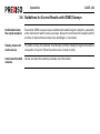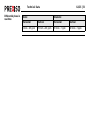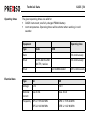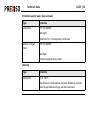
1
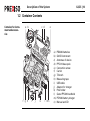
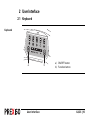
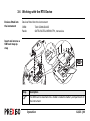
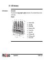
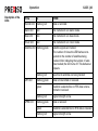
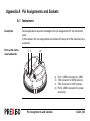
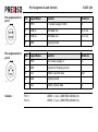
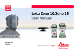
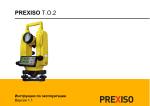
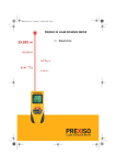
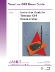
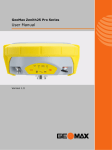
Prexiso G4/G5 User Manual Version 1.0 G4/G5 | 2 Introduction Introduction Purchase Congratulations on the purchase of a Prexiso G4/G5 GNSS instrument. This manual contains important safety directions as well as instructions for setting up the product and operating it. Refer to "5 Safety Directions" for further information. Read carefully through the User Manual before you switch on the product. Product identification Symbols The type and serial number of your product are indicated on the type plate. Enter the type and serial number in your manual and always refer to this information when you need to contact your agency or Prexiso authorised service workshop. Type: _____________________________________ Serial No.: _____________________________________ The symbols used in this manual have the following meanings: Type Description DANGER Indicates an imminently hazardous situation which, if not avoided, will result in death or serious injury. Type Description WARNING Indicates a potentially hazardous situation or an unintended use which, if not avoided, could result in death or serious injury. CAUTION Indicates a potentially hazardous situation or an unintended use which, if not avoided, may result in minor or moderate injury and/or appreciable material, financial and environmental damage. ) Important paragraphs which must be adhered to in practice as they enable the product to be used in a technically correct and efficient manner. Trademarks • Windows is a registered trademark of Microsoft Corporation in the United States and other countries • Bluetooth is a registered trademark of Bluetooth SIG, Inc. • microSD is a trademark of the SD Card Association All other trademarks are the property of their respective owners. Validity of this manual This manual applies to the G4/G5 instruments. Differences between the models are marked and described. Introduction G4/G5 | 3 Introduction Available documentation Name Description/Format G4/G5 | 4 PREXISO User Manual Version G4/G5 Quick Guide Provides an overview of the product together with technical data and safety directions. Intended as a quick reference guide. G4/G5 User Manual All instructions required in order to operate the product to a basic level are contained in the User Manual. Provides an overview of the product together with technical data and safety directions. Refer to the following resources for all G4/G5 documentation/software: • the Prexiso G4/G5 CD • www.prexiso.com 9 9 9 Table of Contents In this manual Chapter 1 Description of the System 1.1 1.2 1.3 1.4 2 System Components Container Contents Instrument Components System Concept 1.4.1 Software Concept 1.4.2 Power Concept 1.4.3 Data Storage Concept User Interface 2.1 2.2 3 Page Keyboard Operating Principles Operation 3.1 Equipment Setup 3.1.1 Setting up as a Real-Time Base 3.1.2 Setting up as a Post-Processing Base 3.1.3 Setting Up as a Real-Time Rover 3.1.4 Fixing the handheld to a holder and pole Table of Contents 8 8 10 11 12 12 13 14 15 15 19 20 20 20 23 25 27 G4/G5 | 5 Table of Contents 3.2 3.3 3.4 3.5 3.6 4 Care and Transport 4.1 4.2 4.3 5 3.1.5 Connecting to a Personal Computer 3.1.6 Configuring the Instrument 3.1.7 The Mechanical Reference Plane, MRP Batteries 3.2.1 Operating Principles 3.2.2 Battery for instrument Working with the Data Storage Device Working with the RTK Device LED Indicators Guidelines for Correct Results with GNSS Surveys Transport Storage Cleaning and Drying Safety Directions 5.1 5.2 5.3 5.4 5.5 General Introduction Intended Use Limits of Use Responsibilities Hazards of Use G4/G5 | 6 29 31 32 33 33 35 37 39 41 44 45 45 46 47 48 48 49 51 52 54 5.6 5.7 6 Technical Data 6.1 6.2 7 Electromagnetic Compatibility EMC FCC Statement, Applicable in U.S. G4/G5 Technical Data 6.1.1 Tracking Characteristics 6.1.2 Accuracy 6.1.3 Technical Data Conformity to National Regulations 6.2.1 G4/G5 International Limited Warranty, Software Licence Agreement Appendix A A.1 Pin Assignments and Sockets Instrument Index 64 67 70 70 70 71 73 77 77 81 83 83 85 Table of Contents G4/G5 | 7 Description of the System G4/G5 | 8 1 Description of the System 1.1 System Components Main components Component Description Instrument To receive the satellite signals and calculate a position from the computed ranges to all visible GNSS (Global Navigation Satellite System) satellites. Getac PPS236 handheld Handheld to operate the instrument. Survey field software The software used on the handheld for performing various surveying applications. Instruments Depending on the satellite systems and signals configured, a maximum number of 72 channels (G4) or 120 channels (G5) is allocated. Instrument Description G4 Up to 14 L1, 14 L2 channels (GPS), 12 L1, 12 L2 channels (GLONASS), code and phase, real-time capable Instrument Description G5 Up to 16 L1, 16 L2, (GPS), up to 14 L1, 14 L2 channels (GLONASS), Galileo, code and phase, real-time capable For GLONASS tracking a licence key has to be uploaded to the instrument with Prexiso Assistant. 9 9 9 9 G4 GSM - 9 9 9 G5 GSM-UHF 9 9 9 9 G5 GSM - 9 9 9 Bluetooth Internal radio modem G4 GSM-UHF Internal GSM modem Model Available models Internal battery*1 ) *1 removable Description of the System G4/G5 | 9 G4/G5 | 10 Description of the System 1.2 Container Contents Container for instrument and accessories a b f g h c d i j k e l mn a) b) c) d) e) f) g) h) i) j) k) l) m) n) PBA202 batteries G4/G5 instrument Antennas of device PPC210 base pole Connection screw Carrier Tribrach Measuring tape USB cable Adapter for charger Pole holder Getac PPS236 handheld PCH202 battery charger Manual and CD 1.3 Instrument Components Instrument components d a b e f c ) a) LEMO port 1 b) TNC connector for GSM antenna c) Battery compartment with SIM card and microSD card holder d) LEDs, ON/OFF button and Function button e) LEMO port 2 f) TNC connector for UHF antenna A Bluetooth port is included inside the instrument to enable connectivity to a controller. Description of the System G4/G5 | 11 Description of the System G4/G5 | 12 1.4 System Concept 1.4.1 Software Concept Instrument software Software upload Software type Description Instrument firmware (xx.bin) This important software covers all functions of the instrument. The firmware can be uploaded using Prexiso Assistant. Uploading instrument firmware can take some time. Ensure that the battery is at least 75% full before beginning the upload, and do not remove the battery during the upload process. The instrument has to be restarted after the firmware upload. ) 1.4.2 Power Concept General Use the Prexiso batteries, chargers and accessories or accessories recommended by Prexiso to ensure the correct functionality of the instrument. Power options Power for the instrument can be supplied either internally or externally. Internal power supply: External power supply: One PBA202 battery fitting into the instrument. 9 V to 18 V DC power supply via cable. Description of the System G4/G5 | 13 Description of the System G4/G5 | 14 1.4.3 Data Storage Concept Description Data (GNSS raw data and RINEX data) can be recorded on a microSD card or internal memory. Data storage device microSD card: Internal memory: ) The instrument has a microSD card holder fitted as standard. A microSD card can be inserted and removed. Capacity: Up to 4 GB. The instrument has an internal memory fitted as standard. Available capacity: 256 MB. Unplugging connecting cables or removing the microSD card during the measurement can cause loss of data. Only remove the microSD card or unplug connecting cables when the instrument is switched off. 2 User Interface 2.1 Keyboard Keyboard a User Interface b a) ON/OFF button b) Function button G4/G5 | 15 G4/G5 | 16 User Interface ON/OFF button Button Function ON/OFF • Turn on instrument: Hold button for 1 s. While the instrument is booting all LEDs are lighted (except the blue Bluetooth LED and the red Power LED). Once the instrument has started, the normal LED behaviour starts. ) • Turn off instrument: Hold button for 3 s until instrument beeps 3 times and only the red power LED is lighted. Button Function • Instrument self-check: While the instrument is turned on hold button for 10 s until the instrument beeps once. The instrument performs a self-check. An instrument self-check can be performed to check if the communication of the internal GNSS board, radio module and GSM module is working correctly. – If the green Satellite, UHF and GPRS LED are on, the communication of the internal GNSS board, radio module and GSM module is working correctly. The instrument reboots 5 s after finishing the self-check. – If the red Satellite, UHF or GPRS LED is on, the communication of the internal GNSS board, radio module or GSM module might not work correctly. The instrument starts beeping. Press any key to reboot the instrument and contact your local Prexiso dealer. ) User Interface G4/G5 | 17 G4/G5 | 18 User Interface Function button Button combination ) The function described assumes that the instrument is turned on. Button Function Function • Switch datalink Press and hold button for 1 s to switch between the datalink options UHF, GPRS and Bluetooth. The corresponding green LED flashes. To select the datalink, press and hold the power button for 1 s. ) The function described assumes that the instrument is turned off. Button Function ON/OFF • Function Press and hold buttons for 6 s until all LEDs flash (except for the blue Bluetooth LED). Press and hold Function button for 1 s to switch between the working mode options Static, Base and Rover. The corresponding LED flashes. To select the working mode, press and hold the ON/OFF button for 1 s. Switch working mode 2.2 Operating Principles Operating the instrument The instrument is operated either by the pressing its buttons (ON/OFF button, Function button) or by a handheld. Operation by buttons The instrument is operated by pressing its buttons. Refer to "2.1 Keyboard" for a description of the buttons and their function. Operation by handheld The instrument is operated by a handheld. Refer to the Field Software User Manual for more information. Turn on instrument To turn on the instrument press and hold the ON/OFF button for 1 s. Turn off instrument To turn off the instrument press and hold the ON/OFF button for 3 s until the instrument beeps 3 times and only the red power LED is lighted. User Interface G4/G5 | 19 Operation G4/G5 | 20 3 Operation 3.1 Equipment Setup 3.1.1 Setting up as a Real-Time Base Use The following equipment setup is used for real-time base stations with the need of optimal radio coverage. Raw observation data can also be collected for postprocessing. Equipment setup G4/G5 a b c d e i a) b) c) d) e) f) g) h) i) f g h Operation G4/G5 instrument PBA202 battery RTK antenna PPC210 base pole Connection screw Carrier Tribrach Tripod Getac PPS236 handheld G4/G5 | 21 Operation Equipment setup step-by-step Step Description 1. Set up the tripod. G4/G5 | 22 2. Mount the tribrach on the tripod. 3. Ensure that the tribrach is over the marker. 4. Mount and level the carrier on the tribrach. 5. Mount the connection screw on the carrier. 6. Screw the base pole to the connection screw. 7. Insert the battery into the instrument. 8. Connect the RTK antenna to the instrument. 9. Press the ON/OFF button on the instrument for 1s to switch on the instrument. 10. Screw the instrument onto the base pole. 11. Check that the tribrach and carrier are still level. 12. Connect the handheld to the instrument through Bluetooth. 13. Measure the antenna height using the measuring tape. Refer to "3.1.7 The Mechanical Reference Plane, MRP" for information on the antenna height. 3.1.2 Setting up as a Post-Processing Base Use The following equipment setup is used for static operations over markers. Equipment setup G4/G5 a b c d g e a) b) c) d) e) f) g) f Operation G4/G5 instrument PBA202 battery Connection screw Carrier Tribrach Tripod Getac PPS236 handheld G4/G5 | 23 Operation Equipment setup step-by-step Step Description 1. Set up the tripod. 2. Mount the tribrach on the tripod. 3. Ensure that the tribrach is over the marker. 4. Mount and level the carrier on the tribrach. G4/G5 | 24 5. Mount the connection screw on the carrier. 6. Insert the battery into the instrument. 7. Press the ON/OFF button on the instrument for 1 s to switch on the instrument. 8. Screw the instrument onto the connection screw. 9. Check that the tribrach and carrier are still level. 10. Connect the handheld to the instrument through Bluetooth. 11. Measure the antenna height using the measuring tape. Refer to "3.1.7 The Mechanical Reference Plane, MRP" for information on the antenna height. 3.1.3 Setting Up as a Real-Time Rover Use Equipment setup G4/G5 The following equipment setup is used for real-time rover. a b c d f e Operation a) b) c) d) e) f) G4/G5 instrument PBA202 battery RTK antenna PPC200 pole Pole holder Getac PPS236 handheld G4/G5 | 25 Operation Equipment setup step-by-step G4/G5 | 26 Step Description 1. Attach the pole holder to the ZPC200 pole. Refer to "3.1.4 Fixing the handheld to a holder and pole". 2. Clip the handheld into the holder and lock it by tighten the screw on the holder. 3. Turn on the handheld. 4. Insert the battery into the instrument. 5. Connect the RTK antenna to the instrument. 6. Press ON/OFF button on the instrument for 1 s to switch on the instrument. 7. Screw the instrument to the top of the pole. 8. Connect the handheld to the instrument through Bluetooth. 3.1.4 Fixing the handheld to a holder and pole Components of the pole holder d a e b c Clamp a) Locking pin b) Tightening screw c) Pole clamp Holder d) Tightening screw e) Pin Zenith20_017 Operation G4/G5 | 27 Operation Fixing the handheld to the holder stepby-step G4/G5 | 28 Step Description 1. Insert the pole into the clamp hole. 2. Tighten the clamp with the tightening screw. 3. To attach the holder to the clamp insert the pin into the catch of the clamp while pushing down the locking pin. 4. Place the handheld in the holder. 5. Tighten the screw of the holder to fix the handheld to the holder. 3.1.5 Connecting to a Personal Computer Description Install USB drivers The instrument is connected to a Personal Computer via USB cable. After establishing a connection, the Prexiso Assistant software can be used to set up and configure the instrument, export data from the internal memory or microSD card, enter licence keys and upload firmware. Step Description 1. Start the PC. 2. Run the Setup.exe to install the drivers necessary for the USB cable. Operation G4/G5 | 29 G4/G5 | 30 Operation Connect instrument to PC 3 2 4 Step Description 1. Start the PC. 2. Start Prexiso Assistant by double-clicking the shortcut from the desktop of your PC. 3. Plug the USB cable into Port 1 of the instrument. 4. Turn on the instrument. 5. Plug the USB cable into the USB port of the PC. For Windows XP operating systems: The Found New Hardware Wizards starts up automatically. Check Close. 3.1.6 Configuring the Instrument Description The instrument can be set up as real-time rover or as real-time base by configuring the instrument with the handheld, using Prexiso Assistant or pressing a button combination. Refer to "Button combination". ) Operation G4/G5 | 31 G4/G5 | 32 Operation 3.1.7 The Mechanical Reference Plane, MRP Description The Mechanical Reference Plane: • is where the antenna heights are measured to. • is where the phase centre variations refer to. • varies for different antennas. MRP for instrument The MRP for the instrument is shown in the diagram. a a) The mechanical reference plane is the underside of the instrument. 3.2 Batteries 3.2.1 Operating Principles Charging / first-time use • • • • • Operation / Discharging • • The battery must be charged prior to using it for the first time because it is delivered with an energy content as low as possible. The permissible temperature range for charging is between 0°C to +40°C/ +32°F to +104°F. For optimal charging, we recommend charging the batteries at a low ambient temperature of +10°C to +20°C/+50°F to +68°F if possible. It is normal for the battery to become warm during charging. Using the chargers recommended by Prexiso, it is not possible to charge the battery if the temperature is too high. For new batteries or batteries that have been stored for a long time (> three months), it is effectual to make only one charge/discharge cycle. For Li-Ion batteries, a single discharging and charging cycle is sufficient. We recommend carrying out the process when the battery capacity indicated on the charger or on a Prexiso product deviates significantly from the actual battery capacity available. The batteries can be operated from -20°C to +55°C/-4°F to +131°F. Low operating temperatures reduce the capacity that can be drawn; high operating temperatures reduce the service life of the battery. Operation G4/G5 | 33 Operation ) CAUTION G4/G5 | 34 For power adapter and charger: The product is not designed for use under wet and severe conditions. If unit becomes wet it may cause you to receive an electric shock. Precautions: Use the product only in dry environments, for example in buildings or vehicles. Protect the product against humidity. If the product becomes humid, it must not be used! 3.2.2 Battery for instrument Insert and remove battery step-by-step 1 2 1 3 Step Description 1. Turn the instrument over to gain access to the battery compartment. 2. Press in the two push buttons located on both sides of the battery housing and pull the housing from the battery compartment. The battery is attached to the housing. Operation G4/G5 | 35 Operation Step Description 3. • To insert the battery: Push the battery into the battery housing with the battery contacts facing upwards until the battery locks into position. • To remove the battery: Hold the battery housing and pull the battery from the housing. 4. WARNING G4/G5 | 36 Place the battery housing on top of the battery compartment and press the housing down until it locks into position. If charged or discharged, batteries not recommended by Prexiso may be damaged. They may burn and explode. Precautions: Only charge and discharge batteries recommended by Prexiso. 3.3 Working with the Data Storage Device ) ) • • • • Keep the card dry. Use it only within the specified temperature range. Do not bend the card. Protect the card from direct impacts. Failure to follow these instructions could result in data loss and/or permanent damage to the card. Insert and remove a microSD card stepby-step 1 1 1 4 2 3 Un Operation lo c k G4/G5 | 37 Operation Step ) G4/G5 | 38 Description The microSD card is inserted into a holder inside the battery compartment of the instrument. 1. Remove the battery housing from the battery compartment. Refer to "Insert and remove battery step-by-step" for further information. 2. Loosen the screws of the metal plate and remove the plate to gain access to the microSD card holder. 3. Slide back the lid of the microSD card holder and lift it. 4. Place the card into the holder with the contacts facing downwards and toward the lid. 5. • To insert a microSD card: Place the card into the holder with the contacts facing downwards and toward the lid. • To remove a microSD card: Remove the microSD card from the holder. 6. Close the lid and slide it until it locks into position. 7. Cover the compartment with the metal plate and tighten the screws. 8. Place the battery housing on top of the battery compartment and press the housing down until it locks into position. 3.4 Working with the RTK Device Devices fitted into the instrument Devices fitted into the instrument: GSM: Radio: Telit GC864-QUAD SATEL SATELLINE M3-TR1, transceive Insert and remove a SIM card step-bystep 1 1 4 2 1 3 Step ) Description The SIM card is inserted into a holder inside the battery compartment of the instrument. Operation G4/G5 | 39 Operation Step ) G4/G5 | 40 Description Only use SIM cards without PIN protection. 1. Remove the battery housing from the battery compartment. Refer to "Insert and remove battery step-by-step" for further information. 2. Loosen the screws of the metal plate and remove the plate to gain access to the SIM card holder. 3. Slide back the lid of the SIM card holder and lift it. 4. • To insert a SIM card: Place the SIM card into the SIM card holder with the contacts facing downwards. • To remove a SIM card: Remove the SIM card from the holder. 5. Close the lid and slide it until it locks into position. 6. Cover the compartment with the metal plate and tighten the screws. 7. Place the battery housing on top of the battery compartment and press the housing down until it locks into position. 3.5 LED Indicators LED indicators Description The instrument has Light Emitting Diode indicators. They indicate the basic instrument status. Diagram a b f g h Operation c d i e a) b) c) d) e) f) g) h) i) Satellite LEDs UHF LEDs GPRS LEDs Bluetooth LEDs Power LEDs Static LED RTK Base LED RTK Rover LED Record LED G4/G5 | 41 G4/G5 | 42 Operation Description of the LEDs IF the is THEN Record LED flashing red data is recorded. Static LED red the instrument is in static mode. Base LED red the instrument is in base mode. Rover LED red the instrument is in rover mode. Satellite LED flashing green UHF LED GPRS LED satellite signals are tracked. The number of times the LED flashes corresponds to the number of satellites being tracked. After indicating the number of satellites tracked, the LED turns off. This behaviour repeats. flashing red less than 4 satellites are being tracked. flashing green data is transmitted or received. green Datalink is selected but no RTK data is transmitted or received. flashing red signal strength is low. flashing green data is received. green Datalink is selected but no RTK data is received. flashing red signal strength is low. IF the is THEN Bluetooth LED green a datalink via Bluetooth is available. blue a Bluetooth connection has established. Power LED green power is on. red power is low (< 20%). Operation G4/G5 | 43 Operation G4/G5 | 44 3.6 Guidelines for Correct Results with GNSS Surveys Undisturbed satellite signal reception Successful GNSS surveys require undisturbed satellite signal reception, especially at the instrument which serves as a base. Set up the instrument in locations which are free of obstructions such as trees, buildings or mountains. Steady antenna for static surveys For static surveys, the antenna must be kept perfectly steady throughout the whole occupation of a point. Place the antenna on a tripod or pillar. Centred and levelled antenna Centre and level the antenna precisely over the marker. 4 Care and Transport 4.1 Transport Transport in the field When transporting the equipment in the field, always make sure that you • either carry the product in its original transport container, • or carry the tripod with its legs splayed across your shoulder, keeping the attached product upright. Transport in a road vehicle Never carry the product loose in a road vehicle, as it can be affected by shock and vibration. Always carry the product in its transport container and secure it. Shipping When transporting the product by rail, air or sea, always use the complete original Prexiso packaging, transport container and cardboard box, or its equivalent, to protect against shock and vibration. Shipping, transport of batteries When transporting or shipping batteries, the person in charge of the product must ensure that the applicable national and international rules and regulations are observed. Before transportation or shipping, contact your local passenger or freight transport company. Care and Transport G4/G5 | 45 Care and Transport G4/G5 | 46 4.2 Storage Product Respect the temperature limits when storing the equipment, particularly in summer if the equipment is inside a vehicle. Refer to "6 Technical Data" for information about temperature limits. Li-Ion batteries • • • • • • Refer to "6 Technical Data" for information about storage temperature range. At the recommended storage temperature range, batteries containing a 10% to 50% charge can be stored for up to one year. After this storage period the batteries must be recharged. Remove batteries from the product and the charger before storing. After storage recharge batteries before using. Protect batteries from damp and wetness. Wet or damp batteries must be dried before storing or use. A storage temperature range of -20°C to +30°C/-4°F to 86°F in a dry environment is recommended to minimise self-discharging of the battery. 4.3 Cleaning and Drying Product and accessories • Use only a clean, soft, lint-free cloth for cleaning. If necessary, moisten the cloth with water or pure alcohol. Do not use other liquids; these may attack the polymer components. For power adapter and charger: Use only a clean, soft, lint-free cloth for cleaning. ) • Damp products Dry the product, the transport container, the foam inserts and the accessories at a temperature not greater than 40°C/104°F and clean them. Do not repack until everything is dry. Always close the transport container when using in the field. Cables and plugs Keep plugs clean and dry. Blow away any dirt lodged in the plugs of the connecting cables. Connectors with dust caps Wet connectors must be dry before attaching the dust cap. Care and Transport G4/G5 | 47 Safety Directions G4/G5 | 48 5 Safety Directions 5.1 General Introduction Description The following directions enable the person responsible for the product, and the person who actually uses the equipment, to anticipate and avoid operational hazards. The person responsible for the product must ensure that all users understand these directions and adhere to them. 5.2 Intended Use Permitted use • • • • • Computing with software. Carrying out measurement tasks using various GNSS measuring techniques. Recording GNSS and point related data. Data communication with external appliances. Measuring raw data and computing coordinates using carrier phase and code signal from GNSS satellites. Safety Directions G4/G5 | 49 Safety Directions Adverse use • • • • • • • • • • • WARNING G4/G5 | 50 Use of the product without instruction. Use outside of the intended limits. Disabling safety systems. Removal of hazard notices. Opening the product using tools, for example screwdriver, unless this is permitted for certain functions. Modification or conversion of the product. Use after misappropriation. Use of products with recognisable damages or defects. Use with accessories from other manufacturers without the prior explicit approval of Prexiso. Inadequate safeguards at the working site, for example when measuring on roads. Controlling of machines, moving objects or similar monitoring application without additional control- and safety installations. Adverse use can lead to injury, malfunction and damage. It is the task of the person responsible for the equipment to inform the user about hazards and how to counteract them. The product is not to be operated until the user has been instructed on how to work with it. 5.3 Limits of Use Environment Suitable for use in an atmosphere appropriate for permanent human habitation: not suitable for use in aggressive or explosive environments. DANGER Local safety authorities and safety experts must be contacted before working in hazardous areas, or close to electrical installations or similar situations by the person in charge of the product. ) Environment For power adapter and charger: Suitable for use in dry environments only and not under adverse conditions. Safety Directions G4/G5 | 51 Safety Directions G4/G5 | 52 5.4 Responsibilities Manufacturer of the product Prexiso AG, CH-8152 Glattbrugg, hereinafter referred to as Prexiso, is responsible for supplying the product, including the user manual and original accessories, in a safe condition. Manufacturers of non Prexiso accessories The manufacturers of non Prexiso accessories for the product are responsible for developing, implementing and communicating safety concepts for their products, and are also responsible for the effectiveness of those safety concepts in combination with the Prexiso product. Person in charge of the product The person in charge of the product has the following duties: • To understand the safety instructions on the product and the instructions in the user manual. • To be familiar with local regulations relating to safety and accident prevention. • To inform Prexiso immediately if the product and the application becomes unsafe. • To ensure that the national laws, regulations and conditions for the operation of radio transmitters are respected. WARNING The person responsible for the product must ensure that it is used in accordance with the instructions. This person is also accountable for the training and the deployment of personnel who use the product and for the safety of the equipment in use. Safety Directions G4/G5 | 53 Safety Directions G4/G5 | 54 5.5 Hazards of Use WARNING The absence of instruction, or the inadequate imparting of instruction, can lead to incorrect or adverse use, and can cause accidents with far-reaching human, material, financial and environmental consequences. Precautions: All users must follow the safety directions given by the manufacturer and the directions of the person responsible for the product. CAUTION Watch out for erroneous measurement results if the product has been dropped or has been misused, modified, stored for long periods or transported. Precautions: Periodically carry out test measurements and perform the field adjustments indicated in the user manual, particularly after the product has been subjected to abnormal use and before and after important measurements. DANGER Because of the risk of electrocution, it is dangerous to use poles and extensions in the vicinity of electrical installations such as power cables or electrical railways. Precautions: Keep at a safe distance from electrical installations. If it is essential to work in this environment, first contact the safety authorities responsible for the electrical installations and follow their instructions. WARNING During dynamic applications, for example stakeout procedures there is a danger of accidents occurring if the user does not pay attention to the environmental conditions around, for example obstacles, excavations or traffic. Precautions: The person responsible for the product must make all users fully aware of the existing dangers. WARNING Inadequate securing of the working site can lead to dangerous situations, for example in traffic, on building sites, and at industrial installations. Precautions: Always ensure that the working site is adequately secured. Adhere to the regulations governing safety and accident prevention and road traffic. Safety Directions G4/G5 | 55 Safety Directions G4/G5 | 56 WARNING If computers intended for use indoors are used in the field there is a danger of electric shock. Precautions: Adhere to the instructions given by the computer manufacturer regarding field use with Prexiso products. CAUTION If the accessories used with the product are not properly secured and the product is subjected to mechanical shock, for example blows or falling, the product may be damaged or people can sustain injury. Precautions: When setting-up the product, make sure that the accessories are correctly adapted, fitted, secured, and locked in position. Avoid subjecting the product to mechanical stress. WARNING If the product is used with accessories, for example masts, staffs, poles, you may increase the risk of being struck by lightning. Precautions: Do not use the product in a thunderstorm. DANGER If the product is used with accessories, for example on masts, staffs, poles, you may increase the risk of being struck by lightning. Danger from high voltages also exists near power lines. Lightning, voltage peaks, or the touching of power lines can cause damage, injury and death. Precautions: • Do not use the product in a thunderstorm as you can increase the risk of being struck by lightning. • Be sure to remain at a safe distance from electrical installations. Do not use the product directly under or close to power lines. If it is essential to work in such an environment contact the safety authorities responsible for electrical installations and follow their instructions. • If the product has to be permanently mounted in an exposed location, it is advisable to provide a lightning conductor system. A suggestion on how to design a lightning conductor for the product is given below. Always follow the regulations in force in your country regarding grounding antennas and masts. These installations must be carried out by an authorised specialist. • To prevent damages due to indirect lightning strikes (voltage spikes) cables, for example for antenna, power source or modem should be protected with appropriate protection elements, like a lightning arrester. These installations must be carried out by an authorised specialist. • If there is a risk of a thunderstorm, or if the equipment is to remain unused and unattended for a long period, protect your product additionally by unplugging all systems components and disconnecting all connecting cables and supply cables, for example, instrument - antenna. Safety Directions G4/G5 | 57 G4/G5 | 58 Safety Directions Lightning conductors Suggestion for design of a lightning conductor for a GNSS system: 1) On non-metallic structures Protection by air terminals is recommended. An air terminal is a pointed solid or tubular rod of conducting material with proper mounting and connection to a conductor. The position of four air terminals can be uniformly distributed around the antenna at a distance equal to the height of the air terminal. 2) The air terminal diameter should be 12 mm for copper or 15 mm for aluminium. The height of the air terminals should be 25 cm to 50 cm. All air terminals should be connected to the down conductors. The diameter of the air terminal should be kept to a minimum to reduce GNSS signal shading. On metallic structures Protection is as described for non-metallic structures, but the air terminals can be connected directly to the conducting structure without the need for down conductors. Air terminal arrangement, plan view a b c GS_039 a) Antenna b) Support structure c) Air terminal Grounding the instrument/antenna a b c d e GS_040 a) b) c) d) e) Antenna Lightning conductor array Antenna/instrument connection Metallic mast Connection to earth WARNING Using a battery charger not recommended by Prexiso can destroy the batteries. This can cause fire or explosions. Precautions: Only use chargers recommended by Prexiso to charge the batteries. WARNING If charged or discharged, batteries not recommended by Prexiso may be damaged. They may burn and explode. Precautions: Only charge and discharge batteries recommended by Prexiso. Safety Directions G4/G5 | 59 Safety Directions G4/G5 | 60 CAUTION During the transport, shipping or disposal of batteries it is possible for inappropriate mechanical influences to constitute a fire hazard. Precautions: Before shipping the product or disposing of it, discharge the batteries by running the product until they are flat. When transporting or shipping batteries, the person in charge of the product must ensure that the applicable national and international rules and regulations are observed. Before transportation or shipping contact your local passenger or freight transport company. WARNING High mechanical stress, high ambient temperatures or immersion into fluids can cause leakage, fire or explosions of the batteries. Precautions: Protect the batteries from mechanical influences and high ambient temperatures. Do not drop or immerse batteries into fluids. WARNING If battery terminals come in contact with jewellery, keys, metallised paper or other metals, short circuited battery terminals can overheat and cause injury or fire, for example by storing or transporting in pockets. Precautions: Make sure that the battery terminals do not come into contact with metallic objects. ) For power adapter: WARNING ) If you open the product, either of the following actions may cause you to receive an electric shock. • Touching live components • Using the product after incorrect attempts were made to carry out repairs Precautions: Do not open the product. Only Prexiso authorised service workshops are entitled to repair these products. For power adapter and charger: CAUTION The product is not designed for use under wet and severe conditions. If unit becomes wet it may cause you to receive an electric shock. Precautions: Use the product only in dry environments, for example in buildings or vehicles. Protect the product against humidity. If the product becomes humid, it must not be used! WARNING Incorrect fastening of the external antenna to vehicles or transporters poses the risk of the equipment being broken by mechanical influence, vibration or airstream. This may result in accident and physical injury. Safety Directions G4/G5 | 61 Safety Directions G4/G5 | 62 Precautions: Attach the external antenna professionally. The external antenna must be secured additionally, for example by use of a safety cord. Ensure that the mounting device is correctly mounted and able to carry the weight of the external antenna (>1 kg) safely. WARNING If the product is improperly disposed of, the following can happen: • If polymer parts are burnt, poisonous gases are produced which may impair health. • If batteries are damaged or are heated strongly, they can explode and cause poisoning, burning, corrosion or environmental contamination. • By disposing of the product irresponsibly you may enable unauthorised persons to use it in contravention of the regulations, exposing themselves and third parties to the risk of severe injury and rendering the environment liable to contamination. Precautions: The product must not be disposed with household waste. Dispose of the product appropriately in accordance with the national regulations in force in your country. Always prevent access to the product by unauthorised personnel. Product-specific treatment and waste management information is available from Prexiso AG. WARNING Only Prexiso authorised service workshops are entitled to repair these products. Safety Directions G4/G5 | 63 Safety Directions G4/G5 | 64 5.6 Electromagnetic Compatibility EMC Description The term Electromagnetic Compatibility is taken to mean the capability of the product to function smoothly in an environment where electromagnetic radiation and electrostatic discharges are present, and without causing electromagnetic disturbances to other equipment. WARNING Electromagnetic radiation can cause disturbances in other equipment. Although the product meets the strict regulations and standards which are in force in this respect, Prexiso cannot completely exclude the possibility that other equipment may be disturbed. CAUTION There is a risk that disturbances may be caused in other equipment if the product is used with accessories from other manufacturers, for example field computers, personal computers, two-way radios, non-standard cables or external batteries. Precautions: Use only the equipment and accessories recommended by Prexiso. When combined with the product, they meet the strict requirements stipulated by the guidelines and standards. When using computers and two-way radios, pay attention to the information about electromagnetic compatibility provided by the manufacturer. CAUTION Disturbances caused by electromagnetic radiation can result in erroneous measurements. Although the product meets the strict regulations and standards which are in force in this respect, Prexiso cannot completely exclude the possibility that the product may be disturbed by intense electromagnetic radiation, for example, near radio transmitters, two-way radios or diesel generators. Precautions: Check the plausibility of results obtained under these conditions. WARNING If the product is operated with connecting cables attached at only one of their two ends, for example external supply cables, interface cables, the permitted level of electromagnetic radiation may be exceeded and the correct functioning of other products may be impaired. Precautions: While the product is in use, connecting cables, for example product to external battery, product to computer, must be connected at both ends. Safety Directions G4/G5 | 65 Safety Directions Radios or digital cellular phones WARNING G4/G5 | 66 Use of product with radio or digital cellular phone devices Electromagnetic fields can cause disturbances in other equipment, in installations, in medical devices, for example pacemakers or hearing aids and in aircraft. It can also affect humans and animals. Precautions: Although the product meets the strict regulations and standards which are in force in this respect, Prexiso cannot completely exclude the possibility that other equipment can be disturbed or that humans or animals can be affected. • Do not operate the product with radio or digital cellular phone devices in the vicinity of filling stations or chemical installations, or in other areas where an explosion hazard exists. • Do not operate the product with radio or digital cellular phone devices near medical equipment. • Do not operate the product with radio or digital cellular phone devices in aircraft. 5.7 FCC Statement, Applicable in U.S. ) WARNING The greyed paragraph below is only applicable for products without radio. This equipment has been tested and found to comply with the limits for a Class B digital device, pursuant to part 15 of the FCC rules. These limits are designed to provide reasonable protection against harmful interference in a residential installation. This equipment generates, uses and can radiate radio frequency energy and, if not installed and used in accordance with the instructions, may cause harmful interference to radio communications. However, there is no guarantee that interference will not occur in a particular installation. If this equipment does cause harmful interference to radio or television reception, which can be determined by turning the equipment off and on, the user is encouraged to try to correct the interference by one or more of the following measures: • Reorient or relocate the receiving antenna. • Increase the separation between the equipment and the receiver. • Connect the equipment into an outlet on a circuit different from that to which the receiver is connected. • Consult the dealer or an experienced radio/TV technician for help. Safety Directions G4/G5 | 67 G4/G5 | 68 Safety Directions WARNING Changes or modifications not expressly approved by Prexiso for compliance could void the user's authority to operate the equipment. Labelling G4/G5 ...... ......... ...... ...... ........... ........... Labelling internal battery PBA202 This device complies with part 15 of the FCC Rules. Operation is subject to the following two conditions: (1) This device may not cause harmful interference, and (2) this device must accept any interference received, including interference that may cause undesired operatio Labelling battery charger PCH202 ...... Safety Directions ...... G4/G5 | 69 Technical Data G4/G5 | 70 6 Technical Data 6.1 G4/G5 Technical Data 6.1.1 Tracking Characteristics Instrument channels Depending on the satellite systems and signals configured, a maximum number of 72 channels (G4) or 120 channels (G5) is allocated. G4: G5: ) Up to 14 channels continuous tracking on L1, L2 (GPS); up to 12 channels continuous tracking on L1 and L2 (GLONASS). Up to 16 channels continuous tracking on L1, L2 (GPS); up to 14 channels continuous tracking on L1 and L2 (GLONASS); Galileo. Carrier phase and code measurements on L1 and L2 (GPS) are fully independent with AS on or off. 6.1.2 Accuracy ) Accuracy is dependent upon various factors including the number of satellites tracked, constellation geometry, observation time, ephemeris accuracy, ionospheric disturbance, multipath and resolved ambiguities. The following accuracies, given as root mean square, are based on measurements processed using Prexiso Geo Office and on real-time measurements. The use of multiple GNSS systems can increase accuracy by up to 30% relative to GPS only. Differential code The baseline precision of a differential code solution for static and kinematic surveys is 25 cm. Differential phase in post-processing Static and rapid static Static Kinematic Horizontal Vertical Horizontal Vertical 5 mm + 0.5 ppm 10 mm + 0.5 ppm 10 mm + 1 ppm 20 mm + 1 ppm Technical Data G4/G5 | 71 G4/G5 | 72 Technical Data Differential phase in real-time Static Kinematic Horizontal Vertical Horizontal Vertical 5 mm + 0.5 ppm 10 mm + 0.5 ppm 10 mm + 1 ppm 20 mm + 1 ppm 6.1.3 Technical Data Dimensions The dimensions are given for the housing without the sockets. Height [m] Diameter [m] 0.094 0.188 Weight Instrument weight with battery: 1.32 kg/2.91 lbs. Recording Data (GNSS raw data and RINEX data) can be recorded on a microSD card or internal memory. Type Capacity [MB] Data capacity Internal memory 256 256 MB is typically sufficient for about 30 days data logging at 15 s rate. Power Power consumption: External supply voltage: Instrument, radio excluded: 3.2 W typically, 270 mA Nominal 12V DC, 9 V to 18 V DC Battery internal Type: Voltage: Capacity: Li-Ion 7.4 V PBA202: 2.5 Ah Technical Data G4/G5 | 73 G4/G5 | 74 Technical Data Operating times The given operating times are valid for • G4/G5: instrument; one fully charged PBA202 battery. • room temperature. Operating times will be shorter when working in cold weather. Equipment Electrical data Operating time Type Radio GSM Static - - 6 h continuously Rover SATEL SATELLINE M3-TR1, receive - 4 h continuously Rover - Telit GC864-QUAD 4.5 h continuously Type G4 G5 Voltage 7.4 V 7.4 V Nominal current max. 0.8 A max. 0.8 A Frequency GPS L1 1575.42 MHz GPS L1 1575.42 MHz GPS L2 1227.60 MHz GPS L2 1227.60 MHz Type Environmental specifications G4 G5 GLONASS L1 1602.5625 MHz1611.5 MHz GLONASS L1 1602.5625 MHz1611.5 MHz GLONASS L2 1246.4375 MHz1254.3 MHz GLONASS L2 1246.4375 MHz1254.3 MHz Gain Typically 2.1 dBi Typically 2.1 dBi Noise Figure Typically < 2 dBi Typically < 2 dBi Temperature Type Operating temperature [°C] Instrument -30 to +60 -40 to +80 UHF Tx 0.5 W -30 to +50 -40 to +80 Battery internal -20 to +55 -40 to +70 Technical Data Storage temperature [°C] G4/G5 | 75 Technical Data G4/G5 | 76 Protection against water, dust and sand Type Instrument Protection IP67 (IEC 60529) Dust tight Waterproof to 1 m temporary immersion Battery compartment IP65 (IEC 60529) Dust tight Protected against spray water Humidity Type Protection Instrument Up to 100 % The effects of condensation are to be effectively counteracted by periodically drying out the instrument. 6.2 Conformity to National Regulations Conformity to national regulations For products which do not fall under R&TTE directive: Hereby, Prexiso AG, declares that the product/s is/are in compliance with the essential requirements and other relevant provisions of the applicable European Directives. The declaration of conformity is available from Prexiso AG. 6.2.1 G4/G5 Conformity to national regulations • • • FCC Part 15, 22 and 24 (applicable in US) Hereby, Prexiso AG, declares that the product G4/G5 GSM is in compliance with the essential requirements and other relevant provisions of Directive 1999/5/EC. The declaration of conformity is available from Prexiso AG. Class 1 equipment according European Directive 1999/5/EC (R&TTE) can be placed on the market and be put into service without restrictions in any EEA member state. The conformity for countries with other national regulations not covered by the FCC part 15, 22 and 24 or European directive 1999/5/EC has to be approved prior to use and operation. Technical Data G4/G5 | 77 Technical Data Conformity to national regulations • • • Frequency band G4/G5 | 78 FCC Part 15, 22 and 24 (applicable in US) Hereby, Prexiso AG, declares that the product G4/G5 GSM-UHF, is in compliance with the essential requirements and other relevant provisions of Directive 1999/5/EC. The declaration of conformity is available from Prexiso AG. Class 2 equipment according European Directive 1999/5/EC (R&TTE) for which following EEA Member States apply restrictions on the placing on the market or on the putting into service or require authorisation for use: • France • Italy • Norway (if used in the geographical area within a radius of 20km from the centre of Ny-Ålesund) The conformity for countries with other national regulations not covered by the FCC part 15, 22 and 24 or European directive 1999/5/EC has to be approved prior to use and operation. Type Frequency band [MHz] G4/G5 1227.60 1246.4375 - 1254.3 1575.42 1602.4375 - 1611.5 Bluetooth 2402 - 2480 Type Frequency band [MHz] SATEL SATELLINE 403 - 470 M3-TR1 Telit GC864-QUAD Quad-Band EGSM850 / EGSM900 / GSM1800 / GSM1900 Output power Type Output power [mW] GNSS Receive only Bluetooth 2.5 (Class 2) SATEL SATELLINE M3-TR1 0.5-1.0 Telit GC864-QUAD, EGSM850/900 2 Telit GC864-QUAD, GSM1800/1900 1 Technical Data G4/G5 | 79 G4/G5 | 80 Technical Data Antenna Type Antenna Gain [dBi] Connector Frequency band [MHz] GNSS Internal GNSS antenna element (receive only) - - - Bluetooth Internal Microstrip antenna 1.5 - - GAT1 Detachable λ/2 antenna 4 TNC 400 - 435 GAT2 Detachable λ/2 antenna 4 TNC 435 - 470 TQX-440AE Detachable λ/2 antenna 5 TNC 430 - 450 TQX-0918EL Detachable λ/2 antenna - TNC 824 - 960 / 1710 - 1880 7 International Limited Warranty, Software Licence Agreement International Limited Warranty This product is subject to the terms and conditions set out in the International Limited Warranty which you can download from the Prexiso home page at http://www.prexiso.com or collect from your Prexiso distributor. The foregoing warranty is exclusive and is in lieu of all other warranties, terms or conditions, express or implied, either in fact or by operation of law, statutory or otherwise, including warranties, terms or conditions of merchantability, fitness for a particular purpose, satisfactory quality and non-infringement, all which are expressly disclaimed. Software Licence Agreement This product contains software that is preinstalled on the product, or that is supplied to you on a data carrier medium, or that can be downloaded by you online according to prior authorisation from Prexiso. Such software is protected by copyright and other laws and its use is defined and regulated by the Prexiso Software Licence Agreement, which covers aspects such as, but not limited to, Scope of the Licence, Warranty, Intellectual Property Rights, Limitation of Liability, Exclusion of other Assurances, Governing Law and Place of Jurisdiction. Please make sure, that at any time you fully comply with the terms and conditions of the Prexiso Software Licence Agreement. International Limited Warranty, Software Licence G4/G5 | 81 International Limited Warranty, Software Licence G4/G5 | 82 Such agreement is provided together with all products and can also be referred to and downloaded at the Prexiso home page at http://www.prexiso.com or collected from your Prexiso distributor. You must not install or use the software unless you have read and accepted the terms and conditions of the Prexiso Software Licence Agreement. Installation or use of the software or any part thereof, is deemed to be an acceptance of all the terms and conditions of such Licence Agreement. If you do not agree to all or some of the terms of such Licence Agreement, you must not download, install or use the software and you must return the unused software together with its accompanying documentation and the purchase receipt to the distributor from whom you purchased the product within ten (10) days of purchase to obtain a full refund of the purchase price. Appendix A Pin Assignments and Sockets A.1 Instrument Description Ports at the instrument underside Some applications require knowledge of the pin assignments for the instrument ports. In this chapter, the pin assignments and sockets for the ports of the instrument are explained. a b cd a) b) c) d) Pin Assignments and Sockets Port 1 (LEMO connector for USB) TNC connector for GSM antenna TNC connector for UHF antenna Port 2 (LEMO connector for power and serial) G4/G5 | 83 G4/G5 | 84 Pin Assignments and Sockets Pin assignments for port 1 1 4 2 3 PIN_008 Pin assignments for port 2 1 2 5 3 4 PIN_004 Sockets Pin Signal Name Function Direction 1 PWR 5 V power supply (USB) In 2 USB_D- USB data line In or out 3 USB_D+ USB data line In or out 4 GND Signal ground - Pin Signal Name Function Direction 1 PWR 12 V power supply in In 2 GND Signal and chassis ground - 3 TxD RS232, transmit data Out 4 GND Signal ground - 5 RxD RS232, receive data In Port 1: Port 2: LEMO-1, 4 pin, LEMO EEG.0B.304.CLN LEMO-1, 5 pin, LEMO EEG.0B.305.CLN Index A Antenna Instrument .......................................................... 80 Available instrument models ................................... 9 B Batteries Charging, first-time use .................................... 33 Operation, Discharging ..................................... 33 Battery Change in instrument ....................................... 35 For internal power supply ................................ 13 Internal, instrument ........................................... 73 Bluetooth LED ..................................................................... 41 Buttons Combined pressing ........................................... 18 Function ............................................................. 18 ON/OFF ............................................................... 16 Index C Capacity, memory Instrument ......................................................... 73 D Data recording GNSS raw data .................................................. 73 RINEX ................................................................. 73 Data storage device Available ............................................................ 14 Description of the system ........................................ 8 Dimensions Instrument ......................................................... 73 Documentation ......................................................... 4 E Electrical data instrument ......................................................... 74 Environmental specifications Instrument ......................................................... 75 External power supply ........................................... 13 G4/G5 | 85 Index F FCC Statement ........................................................ 67 Firmware Instrument .......................................................... 12 Upload ................................................................ 12 Frequency band Instrument .......................................................... 78 SATEL SATELLINE M3-TR1 .............................. 79 Telit GC864-QUAD ............................................. 79 G GAT1, antenna ........................................................ 80 GAT2, antenna ........................................................ 80 GPRS LED ..................................................................... 41 I Indicators LED ..................................................................... 41 Insert microSD card ..................................................... 37 SIM card ............................................................. 39 Instrument Status ................................................................. 41 Instrument components ......................................... 11 G4/G5 | 86 Instruments ............................................................... 8 Intended Use ........................................................... 49 Internal power supply ............................................ 13 International Limited Warranty ............................. 81 K Keyboard ................................................................. 15 L Labelling G4/G5 ................................................................. 68 PBA202 ............................................................... 68 PCH202 ............................................................... 69 LED, Description instrument ......................................................... 42 Light Emitting Diode instrument ......................................................... 41 Li-Ion battery ........................................................... 73 Storage ............................................................... 46 M Mechanical Reference Plane .................................. 32 Memory device Available ............................................................ 14 microSD card Insert ................................................................... 37 Remove .............................................................. 37 MRP .......................................................................... 32 O Operating times Instrument .......................................................... 74 Output power instrument .......................................................... 79 SATEL SATELLINE M3-TR1 .............................. 79 Telit GC864-QUAD ....................................... 79, 79 P Pin Assginment ....................................................... 83 Power LED ..................................................................... 41 Power supply .......................................................... 13 Power, instruments ................................................ 73 R Raw data logging GNSS ............................................................ 14, 73 RINEX ........................................................... 14, 73 Index Record LED on instrument ............................................ 41 Recording ................................................................ 73 Remove microSD card ..................................................... 37 SIM card ............................................................. 39 Responsibilities ....................................................... 52 RTK Base LED on instrument ............................................ 41 RTK Rover LED on instrument ............................................ 41 S Safety Directions .................................................... 48 Satellite LED ..................................................................... 41 SD card Memory device .................................................. 14 SIM card Insert .................................................................. 39 Remove .............................................................. 39 Socket ...................................................................... 83 Software Instrument ......................................................... 12 Upload ................................................................ 12 G4/G5 | 87 Index Software Licence Agreement ................................ 81 Specifications, environmental Instrument .......................................................... 75 Static LED on instrument ............................................ 41 Status Instrument .......................................................... 41 T Technical data ......................................................... 70 Temperature Battery internal Operating ...................................................... 75 Storage ......................................................... 75 Instrument Operating ...................................................... 75 Storage ................................................... 75, 75 Temperature range Product, drying .................................................. 47 Temperature, charging internal battery ................ 33 Time, operating ....................................................... 74 TQX-0918EL, antenna ............................................. 80 G4/G5 | 88 U UHF LED ..................................................................... 41 Upload firmware ..................................................... 12 Upload software ..................................................... 12 User Interface .......................................................... 15 User Manual Validity of ............................................................. 3 W Weight Instrument ......................................................... 73 Index G4/G5 | 89 794020-1.0.0en Original text © 2011 Prexiso AG, Glattbrugg, Switzerland PREXISO AG www.prexiso.com