1
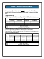
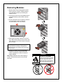
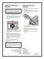
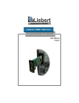
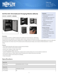
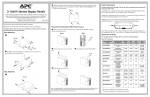
POWER PROTECTION
Nfinity™ Module Replacement
NFINITY MODULE REPLACEMENT
Before installing a Power Module that will increase the rating of the Nfinity UPS (e.g.,
from 8kVA to 12kVA), ensure that the input cabling and circuit breaker protection is
correctly sized to the minimum input protection circuit breaker by referring to the tables
below.
1. Stand-alone UPS or
2. UPS equipped with a Maintenance Bypass Cabinet (Without Transformer)
Max.
System
Load
Rating
Input Voltage – 208VAC
Input Voltage – 240VAC
Max. Current
in UPS mode
Min. Input Protection
Circuit Breaker
Max. Current
in UPS mode
Min. Input Protection
Circuit Breaker
8kVA
36 amps
50 amps
31 amps
50 amps
12kVA
53 amps
75 amps
46 amps
75 amps
16kVA
70 amps
100 amps
62 amps
90 amps
35mm2 (2AWG)
Maximum:
Minimum: 16mm2 (6AWG)
Torque Rating: 2.5-3.0Nm (22-26in/lbs)
Terminal
Block
Details
UPS With Maintenance Bypass Cabinet (With Transformer)
Single Input Feed: All UPS ratings must use 100A input circuit breaker protection
Dual Input Feed: See table below
UPS Feed
Input Voltage – 208VAC
Bypass Feed
Input Voltage – 240VAC
208V or 240V
Max.
System
Load
Rating
Max. Current
in UPS mode
Min. Input
Protection
Circuit Breaker
Max. Current
in UPS mode
Min. Input
Protection
Circuit Breaker
Min. Input
Protection
Circuit Breaker
8kVA
36 amps
50 amps
31 amps
50 amps
100 amps
12kVA
53 amps
75 amps
46 amps
75 amps
100 amps
16kVA
70 amps
100 amps
62 amps
90 amps
100 amps
Terminal
Block
Details
35mm2
Maximum:
(2 AWG)
Minimum: 16mm2 (6 AWG)
Torque Rating: 2.5-3.0Nm (22-26 in/lbs)
Removing Modules
1. Remove bezel cover of appropriate module.
When replacing a Power or Battery Module,
verify the faulty module by confirming the
amber LED is lit.
2. If removing a Control or Power Module with no
redundant modules, switch UPS to manual
bypass.
3. Pull out and lift the lever if replacing a Control
or Power Module, then turn fastener
counterclockwise until it is loosened.
4. Start to pull out module. About 2/3 out it will
stop. Slide module away from the center of the
UPS. Continue to pull until module is removed
(seen at right).
CAUTION
Battery Modules are heavy—30 kg (66 lb).
Make sure to use two people when removing a
Battery Module.
5. Dispose of module in an environmentally
responsible way that complies with local
codes / regulations or return to Liebert for
proper disposal.
Note: Battery Modules may contain shipping
screws. These screws may be removed and
discarded.
WARNING
POTENTIAL TIP HAZARD
Install all modules starting from bottom
to top bays. For module removal start
from top to bottom bays. Do not
remove more than one module at a
time. Failure to do so may cause unit to
tip over and cause serious injury.
Adding or Replacing
Modules
Replacing the User
Interface
NOTE
Power Modules must be installed in a bay in the
top half of the Nfinity frame. Battery Modules
can be installed in any bay of the UPS frame.
1. Lift off user interface and set it on top of the
UPS frame.
2. The attached cable will be connected to an
Intellislot card, found in a port between the
control modules.
1. Lift module to appropriate bay, resting end of
module on bay shelf. Use caution not to rest
the module on the lower bezel cover.
2. Push module into bay. Once halfway in, slide
module sideways toward the center of the
UPS. Continue pushing module until fully
inserted.
3. Remove the cable and the attached Intellislot
card from the UPS.
4. Plug the new Intellislot card into the UPS.
3. Press and turn fastener clockwise until locked.
If replacing a Control or Power Module, press
lever down.
5. Plug the new user interface cable into the
Intellislot card.
6. Set replacement User Interface into proper
position.
4. Wait about 15 seconds as the module
performs a start-up test and synchronizes with
the other modules. Both the amber and green
LEDs should be flashing. A green flashing
LED will then confirm the module is properly
installed.
5. If UPS was placed in bypass manually,
transfer back to UPS operation.
6. Replace bezels.
NOTE
When replacing the Control Module, record user
configuration data before removing. Re-verify
the configuration settings after the new Control
Module is installed.
Technical Support
U.S.A. Technical Support
Worldwide FAX Tech Support
Wordwide Support
E-mail
Web Site
1-800-LIEBERT
+614-841-5471
+614-841-6755
[email protected]
http://www.liebert.com
SL-23952
(11/01) Rev. 1