1
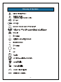
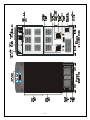
Power System
208 V / 240 V 60Hz
4 to 16 kVA
User Manual
English
IMPORTANT SAFETY INSTRUCTIONS
SAVE THESE INSTRUCTIONS.
This UPS is designed for use on a properly
grounded (earthed), 208/240 VAC, 60Hz supply,
and is to be installed by qualified personnel.
This manual contains important instructions that
should be closely followed during installation
and maintenance of this UPS unit and during the
installation and replacement of power and
battery modules.
ELECTROMAGNETIC COMPATIBILITY - The
Nfinity™ UPS complies with the limits for a
Class A digital device, pursuant to Part 15 of
FCC rules. These limits provide reasonable
protection against harmful interference in a
commercial environment.
This device
generates, uses, and radiates radio frequency
energy and, if not installed and used in
accordance with the instruction manual, may
cause
harmful
interference
to
radio
communications. Operating this device in a
residential area is likely to cause harmful
interference, which the user must correct at their
own expense.
This product is designed for Commercial /
Industrial use only. This product is not intended
for use with life support and other U.S. FDA
designated “critical” devices. Maximum load
must not exceed that shown on the UPS rating
label. See Limited Warranty.
WARNING: Lethal voltages may be present
within this unit even when it is apparently not
operating. Observe all cautions and warnings in
this manual. Failure to do so MAY result in
serious injury or death. Never work alone.
Operate the UPS in an indoor environment only
in an ambient temperature range of 0°C to
+40°C (32°F to +104°F). Install it in a clean
environment,
free
from
conductive
contaminates, moisture, flammable liquids,
gasses, or corrosive substances.
Observe the following precautions when working
with batteries:
§ CAUTION: DO NOT dispose of battery
modules in a fire; the battery module may
explode.
§ CAUTION: DO NOT open or mutilate
batteries; released electrolyte is harmful to
skin and eyes, and may be toxic.
§ CAUTION: A battery can present a risk of
electrical shock and high short circuit
current. The following precautions should
be observed when working on batteries:
§ Remove watches, rings or other metal
objects.
§ Use tools with insulated handles.
§ CAUTION: Lead-acid batteries contain
hazardous toxic materials.
Handle,
transport, and recycle in accordance with
local regulations.
Turn the UPS off and isolate the UPS before
cleaning. Use only a soft cloth, never liquid or
aerosol cleaners. Keep the front and rear vents
free of dust accumulation that could restrict
airflow.
Never block or insert any object into the
ventilation holes or other openings.
This UPS contains user replaceable modules.
No attempts should be made to access the
interior of any module. See troubleshooting
section on module replacement.
1
Glossary of Symbols
2
Introduction
General Description
Modes of Operation
Major Components
3
General Description
Congratulations on your purchase of Liebert’s
Nfinity™ Uninterruptible Power System. As with
every Liebert product, we stand behind our
quality. If you have any questions concerning
this UPS, please feel free to contact your local
sales representative, or call the appropriate
Technical Support number listed in the back of
this manual.
FEATURES:
To ensure proper installation and operation of
this unit, please read this manual thoroughly.
§
Up to 16 kVA of modular back-up
power
§
Continuous power conditioning
§
A user-friendly interface for custom
configuration
§
Continuous system monitoring
§
Warning alarms and event logs
STANDARD COMPONENTS:
SYSTEM DESCRIPTION
The Liebert Nfinity Power System is a modular
UPS intended for use with workstations, servers,
network, telecom or other sensitive electronic
equipment. It provides continuous, high-quality
AC power to your equipment, protecting it from
any power disturbance due to blackouts,
brownouts, surges or noise interference.
The Nfinity modular UPS was designed to
provide maximum system availability to business
critical equipment. Nfinity is also an easily
adaptable UPS system. By simply installing
additional power or battery modules you can
expand your current system capacity or extend
your back-up runtime.
Nfinity has a comprehensive user interface that
can be configured according to the user’s
preference. It also informs the user of details on
the status of the UPS, and keeps a log of
events.
§
Power Modules – for power
conditioning
§
Battery Modules – for back-up power
§
System Control Modules – for system
monitoring and communications
§
LCD display for comprehensive user
indications and programmable controls
§
Output transformer for isolation
COMMUNICATIONS
4
§
Dry contacts
§
RS-232
§
Optional communications via
Intellislot™ communication ports
5
Modes of Operation
The Nfinity UPS is designed to operate as a true
on-line system in the following modes:
Recharge Mode
When AC utility is restored, the unit will then
automatically recharge the battery modules until
they are fully charged.
Normal Mode
The Power Module rectifiers derive power from a
utility AC source and supplies regulated DC
power to the inverter. The module’s inverter
regenerates precise AC power to supply the
connected equipment.
The battery charger
maintains a float-charge on the battery.
Bypass Mode
The bypass provides an alternate path for power
to the connected equipment that operates in the
following manner:
Back-Up Mode
Automatic
When AC utility fails, the connected equipment
is supplied power by the inverter, which obtains
energy from the battery modules. The output
power equipment will not be interrupted during
the failure or restoration of the AC utility source.
In the event of an internal failure or should
the inverter overload capacity be exceeded,
the UPS performs an automatic transfer of
the connected equipment from the inverter
to the bypass source.
Auto Restart Mode
Manual
After a power outage and complete battery
discharge, once the AC utility is restored, the
UPS will automatically restart and resume
supplying power to the connected equipment.
This feature is enabled at the factory, but can be
disabled by the user.
The user can also
program two auto restart delay settings:
1. Battery capacity level (%)
2. Countdown timer
Should the UPS need to be taken out of
service for limited maintenance or repair,
manual activation of the bypass will cause
an immediate transfer of the equipment from
the inverter to the bypass source.
6
Major Components
The following is a general description
of each component and its functions.
Please review this section carefully, as
it will give you a better understanding
as to how Nfinity operates.
Unit Frame
Nfinity’s frame houses all of the other
system components. Looking at the
front of Nfinity™, one will see a series
of plastic bezels. By grabbing these
bezels from the side and pulling out,
you will remove the bezel to reveal the
Battery / Power Module bays. The
bottom bezel covers the cooling fans
and the Manual Bypass Switch.
The User Interface Module is located
above the Power / Battery Module bays
for easy access. From here the user
may find out various information about
Nfinity’s condition. By moving the User
Interface and setting it on top of the
frame, you will see the System Control
Module bays.
Nfinity’s frame with bezels removed
7
User Interface Module
The User Interface Module is the primary source of
communication between the UPS and the user.
From the interface, the user can:
§ View the status of the UPS
§ Custom configure the system
§ Review the event log to assist with
troubleshooting
§ Enable / disable the output power
§ Silence the audible alarm
For a more detailed explanation on how to operate
the User Interface module, see the Controls and
Indicators section of this manual.
User Interface Module
System Control Module
The System Control Module is the
communicative backbone of the UPS. It
gathers input from all modules and processes
the data to control the operation of the
system – including monitoring the condition of
each module. An optional second System
Control Module can be installed to provide full
system
functionality
(operation
and
communication), in the unlikely event a
Control Module should fail.
Under normal operation, the Status LED
(green) will blink and the Fault LED (amber)
will be off. For any condition other than this,
check the Troubleshooting section of this
manual.
System Control Module
8
Power Module
Battery Module
The Power Module maintains the condition of
power in the Nfinity UPS. Each module is an
independent 4-kVA unit, consisting of a power
factor corrected rectifier, battery charger, and
inverter, with associated monitoring and controlcircuitry. The modules are paralleled to provide
greater capacity and/or redundancy. Modules
may be added or replaced on-line with no
interruption or danger to the connected
equipment.
The Battery Modules provide back-up power in
the event of input utility failure. Each module
contains a quantity of ten individual 12-volt valve
regulated (VRLA) battery blocks with associated
monitoring and controls to isolate the battery
module in the event of a battery failure. The
modules are paralleled to provide greater backup time and/or redundancy. Modules may be
added or replaced on-line with no interruption or
danger to the connected equipment.
Power Module
Battery Module
Under Normal Operation, the Status LED (green) will blink and the Fault LED (amber) will be off. For any
condition other than this, check the Troubleshooting section of this manual.
9
Installation
Preparation
Unloading
Cable Installation
Communications
10
Preparation
These installation instructions provide all the
information needed for positioning the UPS
(including environmental requirements) and for
connecting the input and output power cables.
Site Preparation
When deciding where to locate your UPS,
consider the weight and size of the unit. Make
sure that the structural integrity of the floor can
withstand the weight of a fully loaded unit. Refer
to the table below for size and fully populated
weight considerations:
Inspection
Upon receiving the UPS, examine the packaging
for any signs of mishandling or damage. If any
damage is noted, call your local Liebert
representative and/or notify your carrier.
Model
8 bay
12 bay
Environment
Note: Operating in temperatures above 77° F
(25° C) will reduce battery life. The UPS
environment must be free of conductive
contaminants and excessive moisture (water
condensation, flammable vapors, chemical
fumes, or corrosive gasses and liquids).
The tools below are required in order to properly
setup your UPS:
§ Pallet jack
1/2” (13mm) ratchet or wrench
§
Torque Wrench (in / lb)
§
Flathead Screwdriver
§
#2 Phillips Screwdriver
HxWxD
40” x 20” x 28”
53” x 20” x 28”
Check to make sure that your UPS will be
located in a well-ventilated area with at least 12
inches behind it. The UPS is force cooled with
the aid of internal cooling fans. Cooling air
enters from the front of the UPS and is
exhausted through ventilation grills in the back.
It should also have at least 36 inches in front, in
order to change modules when necessary.
Required Setup Equipment
§
Max Weight
871
1186
The unit frame is bolted to the shipping pallet to
ensure safety. It is recommended that a pallet
jack be used to transport the unit to its operating
location (prior to unbolting the unit).
11
Unloading
Unloading the UPS
CAUTION: This UPS is very heavy (see weight
on previous page). At least two people should
be present to unload it off of the pallet.
1. Once the UPS is near the desired operating
location, remove the cardboard cover.
3. Remove the metal ramp from the bottom of
the UPS, rotating it. Fit ramp in pallet slot as
shown above.
4. Using two people, slowly move the UPS
down the ramp until the UPS is on level
ground.
2. Use a ratchet (1/2” or 13mm) or open-ended
wrench to remove the four mounting bolts
from the pallet brackets. Remove mounting
brackets from the pallet and UPS. Keep
brackets for future transportation of UPS, or
for additional stability once in place.
12
Stationary Mounting
5. Once the UPS in its desired location, adjust
the leveling feet to secure its position.
Additional stability can be added by bolting the
mounting brackets (used in shipping) to the
floor.
For greater stability, use a higher-grade bolt.
Refer to the dimensions below when drilling
holes for stationary mounting.
13
Cable Installation
Wiring Preparation
Power Cable Installation
WARNING: Please read this section thoroughly
before attempting to install wiring to this unit.
Be sure that the unit is not connected to any AC
utility power source before installing any wiring
to this unit. This UPS should be installed by a
qualified / certified electrician.
Refer to the charts below when selecting cables:
Power Cable and Protection Ratings
120V
208V
240V
Max Input
Current
Input
Protection
Removing the Cover Plates
Max Output
Current
On the back of the
UPS, cover plates
are over the input
and output
terminals, as
shown on right.
Remove these
using a Phillips
screwdriver. Keep
screws and plates
to one side.
Input / Output
Terminal
Details
67A /
phase
79 A
69 A
100 A
90 A
77 A
67 A
2 AWG max (35 mm²)
6 AWG min (16 mm²)
Torque Rating: 22-26 in/lb
(2.5-3 nm)
90°C rated copper wire is recommended
Notes:
If the start-up is on bypass the UPS has a 3cycle inrush current that is 6 times the rated
output current. This must be taken into account
when selecting the overload protection device at
the AC input supply distribution point. To avoid
random tripping on start up, it is recommended
that the AC input supply be protected with a
circuit breaker capable of withstanding this initial
inrush.
Configuring the Bypass Voltage (TB2)
The UPS voltage is factory set to 208V. Should
the user have a utility supply of 240V, the
bypass voltage jumper will have to be changed
to ensure correct output voltage.
This UPS is fitted with EMI suppression filters.
Earth leakage current is less than 40mA.
Transient and steady state earth leakage
currents may occur when starting the
equipment. This should be taken into account
when selecting ground current detection
devices, as the earth leakage currents of both
the UPS and load will be carried.
Input and output cables must be run in separate
conduits.
A branch rated overcurrent protection device
(circuit breaker or fused disconnect switch) must
be installed for the AC output.
14
Input Wiring (TB1)
Output Wiring (TB3)
To connect the input wiring, follow these steps:
Output wiring may be configured one of two
different ways (240 / 120 or 208 / 120). Refer to
the chart and diagram below when configuring
the output wiring.
1. Locate the
input wiring
access,
remove the
knockout
and pull the
three input
wires
through it,
allowing
some slack
for
installation.
2. Secure the conduit to the rear panel of the
UPS.
3. Input Power cables connect to screw
terminals on the Input Terminal Block
located to the right of the Bypass Voltage
Terminal. Connect the wires to the block
connections as shown below.
Using a
torque wrench, turn the screws clockwise
until tightened to the proper torque value.
Insert the ground wire through the grounding
lug and tighten it to the proper torque value.
Note the Neutral / Ground jumper
on the terminal above.
Voltage
Terminals
120
1, 4
3, 4
208
240
2, 3
1, 3
Only use the connections listed above. Other connections
will produce non-standard voltages.
The Nfinity UPS contains an isolation
transformer that generates a neutral
conductor for the connected equipment.
The UPS is a separately derived source
and contains a neutral to ground bonding
jumper. A grounding electrode conductor
(GEC) must be installed in accordance
with national and local wiring code /
regulations.
Grounding Conductor Installation
An insulated grounding conductor must be
identical in size, insulation material, and
thickness as the grounded and ungrounded
branch-circuit supply conductors. This cable
must be green with or without one or more
yellow stripes, and is to be installed as part of
the branch circuit that supplies the unit or
system.
The grounding conductor is to be grounded to
earth at the service equipment or, if supplied by
a separately derived system, at the supply
transformer or motor-generator set.
15
REPO Switch
Connecting to External Panel Boards
Nfinity is equipped with a Remote Emergency
Power Off (REPO) Switch.
If connected equipment will operate at 240 / 120
VAC, use a standard single-phase panel board.
UPS Output
Panel Board
Input
The user must supply a means of interfacing
with the REPO circuit to allow disconnecting
the UPS input feeder breaker to remove all
sources of power to the UPS and connected
equipment to comply with national and local
wiring codes / regulations.
Remove
jumper
before
wiring.
If connected equipment will ONLY operate at
208 / 120 VAC, use a three-phase panel board.
Ensure that all 120V equipment is connected
L1 – N, L3 – N. Ensure that all 208V equipment is
connected L1 – L2.
UPS Output
Panel Board
Input
1 = 24V DC, 35 mA
2 = sense
3 = sense
4 = ground
If the installation does not require connection
to a REPO system, the jumper must be
removed.
Caution: To maintain safety (SELV) barriers
and electromagnetic compatibility signal
cables should be segregated and run
separately from power cables.
16
Communication
COM Ports
Nfinity is able to communicate through multiple
communication ports simultaneously.
Pin Assignment
Intellislot™ Ports
The following communication cards may be
used with Nfinity:
COM 1 – Relay Contacts
Relay contacts are available through a DB-9F
communications connector.
Contact closure
provides the following:
Pin
1
4
5
7
8
9
Intellislot™ SNMP cards – allows the Nfinity
communicate intelligently with your Ethernet
network. The SNMP card must be installed in
port 1; any additional cards can be added in
consecutive ports.
Assignment
Low Battery (normally open)
UPS shutdown in battery mode
(5-12 V DC for 1.5 sec)
Common
Low Battery (common)
On Battery (common)
On Battery (normally open)
Intellislot™ MultiPort4 cards– allows up to
four client computer systems to simultaneously
monitor the status of Nfinity.
Intellislot™ Relay Contacts cards – provides
contact closures for remote monitoring of alarm
conditions; On Battery, On Bypass, Low Battery,
Summary Alarm, UPS Fault and On UPS
signals. It will integrate with AS400 computers
(additional cable required) and other monitoring
systems.
The contacts are rated 48V DC, 1 Amp
maximum and are compatible with the SiteNet
MultiLink software.
COM 2 – Serial
Nfinity is able to communicate via Liebert
proprietary protocol. The pin-out configuration
of the DB-9 connector is:
Pin
2
3
5
Assignment
Transmit Data
Receive Data
Common
17
Operating Instructions
Controls and Indicators
Operating Procedures
Main Menu
18
Controls and Indicators
Display Controls
The Front Display Panel informs the user of the status of the UPS, and lets him configure the UPS to his
own needs or preferences through the user interface.
It consists of a series of Status LED’s, a 4 line by 20 character LCD display window, and buttons for
navigation (as displayed above).
Buttons
LEDs
Refer to the legend below in order to properly
navigate the Nfinity User Interface.
Refer to the legend below to indicate occurrence
when an LED is lit.
!
Fault / Warning
Solid- A UPS fault condition has occured.
Flashing- A Warning has occured. Consult event log.
AC Input - AC utility is available
On Bypass - The Bypass is supplying the power
Inverter On - The Inverter is supplying the power
On Battery - Battery is supplying power to the inverter
AC Output - Power is available to supply the load
19
Status LED Modes
LED Off
LED On
LED Flashing
UPS is Off or Initializing
UPS On, Utility Good and Output Off
UPS On, Utility Good and Output On
(Normal Operation)
UPS On, Utility Bad and Output On
(On Battery Operation)
UPS On, Utility Bad, and Output Off
Unit in Bypass Operation
(Manual or Automatic)
Unit in Manual Bypass Operation with
Utility out of Bypass Operation Range
Shutdown Due to end of Discharge
20
Navigating the Menu
In order to review or change any settings on the
UPS, it must be navigated using the buttons
seen on the previous page. Because some
menus contain more than four rows of
information, you may see an arrow on the
display pointing up or down (as shown below) –
indicating to scroll using the $ or # buttons.
If you are scrolling through any of the main
menus, items will scroll one line at a time with
the menu heading on the top line:
Pressing # reveals:
Note the arrows on the screen indicating that the
user scroll up or down to reveal more
information.
21
Operating Procedures
Start-up and Initialization
Manual Transfer to Bypass
Follow these steps in order to start up the UPS.
In the event of a UPS overload or failure, the
UPS will transfer to bypass via its automatic
bypass switch. It is possible for the user to
manually transfer the UPS to bypass by
operating the manual bypass switch located
behind the lowest front cover to the bypass
position. To transfer the UPS from bypass to
normal mode, simply operate the manual bypass
switch back to the UPS position.
1. Close Input Circuit Breaker (CB1) and close
the Enable Switch (SW2).
Ensure the
manual bypass switch is in UPS position.
You should see the following on the LCD
display window:
2. Press & button.
It should be noted that the load is not protected
from utility interruptions when in bypass mode.
3. Press % to access the main menu.
Shutting down the UPS
Use the following procedure to power down the
UPS.
1. Press & to disable
connected equipment.
power
from
the
2. Verify request to disable the output by
pressing %.
3. Turn off the Enable Switch (SW2). Open the
Input Circuit Breaker (CB1).
22
Main Menu
After initialization, the % button will take you to the main menu. From here you may check on the status
of the UPS, review the event and alarm log, configure your UPS, and even receive instructions on
replacing modules. The main menu is divided into five sub-menus as shown below:
Use the $ # buttons to select the desired menu item and press % to access the appropriate sub-menu.
23
UPS Status Screen
From the main menu the user may select UPS Status and press %. Once at the UPS Status Screen, the
user may access any information on the present condition of the UPS. Note the chart below when
reviewing the UPS. Any underlined text indicates measured parameters.
24
UPS Configuration Screen
Review Settings
Follow this procedure to review your UPS
configuration settings.
Any underlined text
indicates factory default values.
Follow the menus below by pressing # or $ to
review the settings:
Main Menu
>
UPS Configuration
>
Review Settings
Voltage Settings
Voltage Settings
Input 208/120 LLG
Battery Settings
Battery Settings
Test intervl 2 weeks
on Wed at 06 :00
Low Batt Warn : 2 min
Alarm Settings
Alarm Settings
Power: N+1
Max Load: xx.x kVA
Service Contact
Service Contact
Liebert Corp.
1-800-543-2378
25
Set Password: Set a Password to prevent
unauthorized
users
from
changing
the
configuration of the Nfinity. It can be up to 7
characters in length. Once set, the password
will be required to change the configuration.
Change Configuration Settings
Change Settings Menu
Starting from the Main Menu, locate and press
UPS Configuration. From the UPS Configuration
screen, select the Change Settings option. Here
one may configure Nfinity from a large variety of
selections. Items indicated by an asterisk (*) or
underlined are the selected settings.
Main Menu
Auto Battery Test: Configure when and how
often the Nfinity’s automatic battery test will run.
This test is designed to ensure Battery system
integrity and warn of early problems.
>
UPS Configuration
>
Change Settings
Low Battery Warning: Notifies user as to how
much runtime is available. Can be set from 1 to
30 minutes.
Input Voltage: Select the required input voltage
setting. This voltage must match the bypass
voltage jumper setting.
Input Voltage
* 208/120 LLNG
208/120 LLNG
26
Set Date/Time: Allows user to enable DST
(Daylight Savings Time), change the Day, Date
and Time setting on Nfinity. When enabled, the
time will automatically adjust to Daylight
Savings.
Auto Restart: Automatically restarts once both
delay parameters (battery capacity percentage
and countdown timer) are met.
User Settings: From here one can enter the
UPS ID or adjust the contrast of the user
interface LCD.
Max Load Alarm Set: Allows an alarm to set
when Nfinity’s load reaches a specific level.
UPS Shutdown Delay: Delays UPS shutdown
for specified amount of time after receiving
shutdown command via communications (serial
or SNMP).
27
Remote Shutdown: Enables / Disables the
Remote Communications Shutdown.
If you are using SiteNet™ software, this
parameter should be enabled in order for the
UPS output to be turned off once the operating
system has been shutdown.
Redundant Alarm Set: Sets Alarm to notify
user when redundancy is no longer available.
UPS Test: Allows user to test the Batteries,
LED’s, LCD, or Alarm.
External Battery: Sets total amp-hour for
external batteries to provide a more accurate
runtime remaining value on the LCD display and
through communications.
Service Contact: Set a contact for the user to
reach if problems occur.
Enter in the following when using the External
Battery Cabinets with Chargers.
(P/N: PB10SLF105WC120)
# Cabinets
1
2
3
4
5
6
28
AH Value
0105
0210
0315
0420
0525
0630
Event Log
Alarm Log
One may open the Event Log from the main
menu. By accessing the Event Log, the user
may scroll through the Nfinity’s past 255
occurrences in chronological order by pressing
the $ # buttons.
When an alarm sounds, the User Interface LCD
will display a general explanation as to what the
alarm is indicating. These alarms will also be
displayed in the Alarm Log, which will display
the last 32 alarm messages. To view these
messages in chronological order, press the $ #
buttons.
The first line of a typical alarm log screen will
display the reason for the alarm occurrence.
The second line will give a more specific detail
of the occurrence (i.e.; module serial number).
Press " to go back to the main menu.
Below is a list of possible events / alarms.
The typical event log screen will display the
event number and reference code on the first
line. The purpose of this code is to assist
factory
trained
service
personnel
in
troubleshooting.
Please make a note of the
code number when contacting technical support.
The second line contains the event description.
The third line will have either more detail about
the event, a serial number indicating as to which
module the event occurred, or be left blank. The
last line will show the date and time the event
occurred.
Occurrence
Battery EOD
Battery Mod Removed
Battery Module Added
Battery Module Fail
Battery Test Fail
Battery Test Pass
Display Panel Added
Display Panel Removed
Firmware Error
General UPS Fail
Main Control Fail with
redundant control
Max Load Alarm
Power Mod Added
Power Mod Failure
Power Mod Removed
Red. Power Alarm
Transformer Fan Fail
UPS Auto Restart
UPS CANBus Fail
UPS Low Battery
UPS on Battery
UPS on Bypass (auto)
UPS on Bypass (manual)
UPS Shutdown
UPS Shutdown Imminent
Wrong Voltage
Press " to go back to the main menu.
In the event of an event / alarm, the User
Interface LCD will display the last message
regardless of the default screen. A list of
possible event / alarm messages is displayed at
right. If you encounter one of these or other
messages and are unsure of the corrective
action to take, please contact a qualified Liebert
representative at the number listed in the back
of this manual.
For more information regarding events, consult
the troubleshooting section.
29
Event
4
4
4
4
4
4
4
4
4
4
4
Alarm
4
4
4
4
4
4
4
4
4
4
4
4
4
4
4
4
4
4
4
4
4
4
4
4
4
4
4
4
4
4
Module Replacement
The user interface also supplies instructions for
removing and replacing modules. From the
main menu, access the module replacement
screen and select the type of module. Refer to
the screens below for reference:
For more details on module replacement, consult the troubleshooting section of this user manual.
30
Troubleshooting
Alarm Messages
Module LED Indication
Module Replacement
31
Alarm Messages
In the event of an alarm, the User Interface LCD will display the last message regardless of the default
screen. A list of possible alarm messages is displayed below. If you encounter one of these or other
alarm messages and are unsure of the corrective action to take, please contact a qualified Liebert
representative at the number listed in the back of this manual.
Alarm Message
Cause
Action
Battery Module Failure
General UPS Failure
Battery Module is no longer working
properly.
A Power Module is no longer working
properly.
The UPS is operating on bypass.
Battery Test Failed
Unit has detected a battery module problem.
Redundant Power Alarm
The UPS is no longer redundant.
Maximum Load Alarm
Maximum load has been exceeded.
System Control
Module Failure
Firmware version error
System Control Module no longer working
properly.
Firmware is incompatible.
Refer to Module LED indication section
for corrective action.
Replace the faulty Power Module by
following the procedure in this manual.
Contact a Liebert Global Services at
1-800- 543-2378.
Verify the battery status via the display
and perform self-battery test.
Replace faulty module to regain
redundancy.
Insert additional modules to increase
load capacity or reduce current load.
Replace faulty module.
On Battery
Low Battery
UPS on Bypass (auto)
Load is currently being supplied from UPS.
Battery power is low.
UPS switched to auto bypass.
UPS on Bypass (manual)
Transformer fan failure
User switched UPS to manual bypass.
The transformer cooling fans are no longer
working properly.
The internal communications are not
working properly.
The UPS is about ready to shut down
Power Module Failure
UPS CanBus Failure
UPS Shutdown Imminent
Wrong Voltage
The input voltage configuration and bypass
jumper settings DO NOT MATCH.
32
Download latest firmware version from
www.liebert.com.
Wait for input AC to return.
Allow batteries time to recharge.
Alarm screen should indicate reason
for auto bypass.
When ready, switch back to UPS.
Contact a Liebert Global Services at
1-800- 543-2378.
Contact a Liebert Global Services at
1-800- 543-2378.
Check for faulty modules, output
overloads, or Contact a Liebert Global
Services at 1-800- 543-2378.
Check to make sure the bypass
voltage matches the input voltage and
ensure the input voltage configuration
matches the bypass jumper setting.
Module LED Indication
On every Battery, Power or Control Module are two LEDs to help inform the user of the module status.
Refer to the chart below for Power and Battery Modules:
Status LED
(Green)
Fault LED
( Amber)
OFF
OFF
OFF
FLASHING
FLASHING
FLASHING
OFF
ON
ON
ON
ON
OFF
FLASHING
ON
FLASHING
OFF
ON
FLASHING
Module Status
Module not inserted into frame.
System is OFF.
Module is initializing (max 10 seconds*).
Normal Operation
Module is in start-up qualification mode, or module warning. **
Module failed, is off-line and module control is functioning.
Abnormal operation, re-insert module. If this persists, call Liebert Global
Services at 1-800- 543-2378.
* If this persists for more than 10 seconds, check to verify the lever is in the down position or the module is faulty.
** If both Green and Amber LEDs are flashing for more than 30 seconds, then re-insert module.
33
Module Replacement
Occasionally a control, battery or power module
will need to be removed or replaced. Follow the
instructions below when such an event occurs.
To order additional modules, contact your
Liebert representative or call 1-800-LIEBERT.
Removing Modules
1. Remove bezel cover of appropriate module.
When replacing a Power or Battery Module,
verify the faulty module by confirming the
amber LED is lit.
2. If removing a Control or Power Module with
no redundant modules, switch UPS to
manual bypass.
3. Pull out and lift the lever if replacing a
Control or Power Module, then turn fastener
counter-clockwise until it is loosened.
4. Start to pull out module. About 2/3 out it will
stop. Slide module away from the center of
the UPS. Continue to pull until module is
removed. (Seen at right)
Caution: Battery Modules are heavy (66
lbs, 30 kg). Make sure to use two people
when removing a Battery Module.
WARNING
POTENTIAL TIP HAZARD
Install all modules starting from
bottom to top bays. For module
removal, start from top to bottom
bays. Do Not remove more than one
module at a time. Failure to do so
may cause unit to tip over and cause
serious injury.
5. Dispose of module in an environmentally
responsible way that complies with local
codes / regulations or return to Liebert for
proper disposal.
Note: Battery Modules may contain shipping
screws. These screws may be removed and
discarded.
34
Replacing Modules
Replacing the User Interface
1. Lift module to appropriate bay, resting end
of module on bay shelf. Use caution not to
rest the module on the lower bezel cover.
1. Lift off user interface and set it on top of the
UPS frame.
2. The attached cable will be connected to an
Intellislot card, found in a port between the
control modules.
2. Push module into bay. Once half way in,
slide module sideways toward the center of
the UPS. Continue pushing module fully
inserted.
3. Press and turn fastener clockwise until
locked. If replacing a Control or Power
Module, press lever down.
3. Disconnect the cable from the Intellislot
card.
4. Plug the new user interface cable into the
Intellislot card.
4. Wait about 15 seconds as the module
performs a start-up test and synchronizes
with the other modules. Both the amber and
green LEDs should be flashing. A green
flashing LED will then confirm the module is
properly connected.
5. Set replacement User Interface into proper
position.
5. If UPS was placed in bypass manually,
transfer back to UPS operation.
6. Replace bezels.
35
Maintenance
Proper Care
Scheduled Maintenance
Replacing Fan Filters
36
Maintenance
Proper Care
Replacing Fan Filters
Keeping your Liebert Nfinity UPS operating
properly is imperative to optimal performance
and life of the unit. It is recommended that a
certified technician perform preventive and
corrective maintenance. Liebert Global Services
(LGS) is dedicated to ensuring the highest level
of performance and unmatched support for your
Nfinity UPS. Contact an LGS representative at
1-800-LIEBERT for services to guarantee
maximum reliability and system availability.
Nfinity’s intake fans contain filters that will need
to be replaced / cleaned periodically, depending
on the surrounding environment. Check by
removing the bottom bezel and noting the
condition of the two filters. If filters are dirty,
replace them by removing the plastic cover over
the filter frame and inserting a new filter in its
place. Use caution when replacing filters when
fans are running.
Scheduled Maintenance
It is recommended the following maintenance is
performed at least monthly:
§ Clean unit
§ Clean / replace filters
§ Verify proper airflow
It is recommended the following maintenance is
performed annually:
§ Verify all power modules are operating
properly.
§ Verify all battery modules are operating
properly.
§ Verify redundancy (if applicable).
The fan filters are washable and can be reused.
To wash filters, place them under a running
faucet (with the dirt side down) to remove dirt
and dust.
Blot dry with a towel and allow airdrying before reusing.
37
Reference
Specifications
Battery Run Times
Warranty
Technical Support
38
Specifications
General & Environmental
Unit Rating
Units
kVA
kW
4
4
2.8
8
8
5.6
FCC Part 15, Class A
UL 1778; c-UL
IEEE C62.41, Category B
Conducted and Radiated EMC Levels
Compliant Safety Standards
Compliant Immunity Standards
Mechanical
Dimensions:
Units
Width
Depth
Height
8 Bay
20 (508.0)
28 (711.2)
40 (1016.0)
In (mm)
Environmental
Operating Temperature (max)
Relative Humidity
Maximum operating altitude
Nominal heat dissipation
Acoustic noise level
Units
F (C)
Ft. (M)
BTU/Hr
dBA
Input Data
Nominal input voltage
Power factor
Input frequency (nominal)
Input frequency range
Units
VAC
Cos Ø
Hz
Hz
Battery Module
Number of lead acid batteries
Number of battery cells
Battery capacity
Units
Autonomy time (full load)
mins
Maximum charge current (full load)
Nominal Voltage
Recharge Time
A
VDC
Hrs
Output Data
Output voltage
Voltage regulation
Voltage stability (100% step load)
Recovery time
Units
VAC
%
%
msec
1062
%
Output frequency
Efficiency at 100% load
Output overload capability
Hz
%
%
16
16
11.2
12 Bay
20 (508.0)
28 (711.2)
53 (1346.2)
32° - 104° (0° - 40°)
0-95% non-condensing
10,000 (3000)
2124
3186
<62 @ 1 meter
4248
170 to 276
>.98
60
40-70
10
60
9
6
(With an equal number of Battery & Power Modules,
in a non-redundant configuration)
3
120
3-5 (to 90% capacity)
A/hr
Voltage distortion:
12
12
8.4
208/120 or 240/120
±3
±7
96
<3 THD, linear load
<7 THD, non-linear load
60
89
110-125% for 10 min
126-150% for 10 sec
>151 – 200% for 2 cycles
39
Battery Run Times
8 Bay Frame
Internal and External (minutes)
Load
Load
Quantity of
Quantity of
Battery Modules
External Battery Cabinets with charger
VA
Watts
1
2
3
4
5
6
7
1
2
3
4
5
6
16,000
11,200
-
-
-
6
-
-
-
24
60
100
120
180
240
15,500
10,850
-
-
-
6
-
-
-
26
63
107
140
195
255
15,000
10,500
-
-
-
6
-
-
-
27
67
114
160
210
270
14,500
10,150
-
-
-
6
-
-
-
28
70
120
180
225
285
14,000
9,800
-
-
-
7
-
-
-
30
73
127
190
240
300
13,500
9,450
-
-
-
7
-
-
-
31
77
135
200
252
320
13,000
9,100
-
-
-
8
-
-
-
32
80
142
210
264
340
12,500
8,750
-
-
-
8
-
-
-
34
85
150
220
276
360
12,000
8,400
-
-
6
9
12
-
-
36
90
157
230
288
375
11,500
8,050
-
-
6
9
13
-
-
38
95
165
240
300
390
11,000
7,700
-
-
6
10
14
-
-
40
100
173
255
320
405
10,500
7,350
-
-
7
10
15
-
-
42
110
180
270
340
420
10,000
7,000
-
-
7
11
18
-
-
45
120
195
285
360
450
9,500
6,650
-
-
8
13
18
-
-
50
130
210
300
390
480
9,000
6,300
-
-
9
14
19
-
-
53
140
225
320
420
510
8,500
5,950
-
-
9
15
20
-
-
57
150
240
340
450
540
8,000
5,600
-
6
10
18
21
26
-
60
160
260
360
480
570
7,500
5,250
-
6
11
18
23
28
-
65
170
280
390
510
600
7,000
4,900
-
7
13
19
25
29
-
70
180
300
420
540
660
6,500
4,550
-
8
14
21
27
30
-
80
200
330
480
600
720
6,000
4,200
-
9
18
24
29
36
-
90
220
360
510
660
810
5,500
3,850
-
10
19
26
30
39
-
100
240
420
540
720
900
5,000
3,500
-
12
20
29
36
43
-
120
270
450
600
810
1,000
4,500
3,150
-
14
24
30
40
46
-
140
300
480
720
900
1,100
4,000
2,800
6
18
26
36
43
49
52
160
360
540
810
1,080
1,200
3,500
2,450
7
19
29
41
48
52
56
180
420
600
900
1,260
1,440
3,000
2,100
9
24
36
46
51
56
62
210
480
720
1,050
1,440
1,620
2,500
1,750
12
29
43
51
56
63
68
240
600
900
1,200
1,620
1,800
2,000
1,400
18
36
50
57
64
68
72
360
720
1,200
1,440
1,800
2,880
1,500
1,050
24
46
56
65
69
73
74
480
900
1,440
2,400
3,000
3,600
1,000
700
36
56
68
73
74
75
78
720
1,440
2,400
3,600
4,320
4,320
900
630
39
59
69
73
75
78
78
900
1,800
3,000
4,320
4,320
4,320
800
560
43
63
72
74
76
78
79
1,080
2,100
3,600
4,320
4,320
4,320
700
490
48
68
73
75
78
79
79
1,260
2,400
4,320
4,320
4,320
4,320
600
500
420
350
51
56
69
72
74
75
77
78
79
79
79
80
80
80
1,440
1,440
3,000
3,600
4,320
4,320
4,320
4,320
4,320
4,320
4,320
4,320
Note: Back-up times are in minutes and are based upon resistive loading at an ambient of 25°C, for non-redundant (standard)
configurations. Back-up times for external battery cabinets with chargers include internal battery modules that are equal to the
number of power modules in the UPS frame.
40
Battery Run Times
12 Bay Frame
Internal and External (minutes)
Load
Load
Quantity of
Quantity of
Battery Modules
External Battery Cabinets with charger
VA
Watts
1
2
3
4
5
6
7
8
9
10
11
1
2
3
4
5
6
16,000
11,200
-
-
-
6
8
10
13
18
-
-
-
24
60
100
120
180
240
15,500
10,850
-
-
-
6
8
11
14
18
-
-
-
26
63
107
140
195
255
15,000
10,500
-
-
-
6
9
11
15
18
-
-
-
27
67
114
160
210
270
14,500
10,150
-
-
-
6
9
12
15
19
-
-
-
28
70
120
180
225
285
14,000
9,800
-
-
-
7
9
13
18
19
-
-
-
30
73
127
190
240
300
13,500
9,450
-
-
-
7
10
14
18
20
-
-
-
31
77
135
200
252
320
13,000
9,100
-
-
-
8
11
14
18
21
-
-
-
32
80
142
210
264
340
12,500
8,750
-
-
-
8
11
15
19
22
-
-
-
34
85
150
220
276
360
12,000
8,400
-
-
6
9
12
18
20
23
26
-
-
36
90
157
230
288
375
11,500
8,050
-
-
6
9
13
18
20
24
27
-
-
38
95
165
240
300
390
11,000
7,700
-
-
6
10
14
19
21
25
29
-
-
40
100
173
255
320
405
10,500
7,350
-
-
7
10
15
19
23
27
29
-
-
42
110
180
270
340
420
10,000
7,000
-
-
7
11
18
20
25
28
30
-
-
45
120
195
285
360
450
9,500
6,650
-
-
8
13
18
21
26
29
31
-
-
50
130
210
300
390
480
9,000
6,300
-
-
9
14
19
24
27
30
36
-
-
53
140
225
320
420
510
8,500
5,950
-
-
9
15
20
25
29
31
38
-
-
57
150
240
340
450
540
8,000
5,600
-
6
10
18
21
26
30
36
39
43
-
60
160
260
360
480
570
7,500
5,250
-
6
11
18
23
28
30
38
42
45
-
65
170
280
390
510
600
7,000
4,900
-
7
13
19
25
29
36
41
44
48
-
70
180
300
420
540
660
6,500
4,550
-
8
14
21
27
30
38
43
47
50
-
80
200
330
480
600
720
6,000
4,200
-
9
18
24
29
36
42
46
49
51
-
90
220
360
510
660
810
5,500
3,850
-
10
19
26
30
39
44
49
51
54
-
100
240
420
540
720
900
5,000
3,500
-
12
20
29
36
43
48
51
54
56
-
120
270
450
600
810
1,000
4,500
3,150
-
14
24
30
40
46
50
54
57
59
-
140
300
480
720
900
1,100
4,000
2,800
6
18
26
36
43
49
52
56
59
63
66
160
360
540
810
1,080
1,200
3,500
2,450
7
19
29
41
48
52
56
60
64
68
69
180
420
600
900
1,260
1,440
3,000
2,100
9
24
36
46
51
56
62
65
68
69
72
210
480
720
1,050
1,440
1,620
2,500
1,750
12
29
43
51
56
63
68
69
72
73
73
240
600
900
1,200
1,620
1,800
2,000
1,400
18
36
50
57
64
68
72
73
74
74
75
360
720
1,200
1,440
1,800
2,880
1,500
1,050
24
46
56
65
69
73
74
75
76
78
78
480
900
1,440
2,400
3,000
3,600
1,000
700
36
56
68
73
74
75
78
78
79
79
80
720
1,440
2,400
3,600
4,320
4,320
900
630
39
59
69
73
75
78
78
79
79
80
80
900
1,800
3,000
4,320
4,320
4,320
800
560
43
63
72
74
76
78
79
79
80
80
80
1,080
2,100
3,600
4,320
4,320
4,320
700
490
48
68
73
75
78
79
79
80
80
81
81
1,260
2,400
4,320
4,320
4,320
4,320
600
420
51
69
74
77
79
79
80
80
81
81
82
1,440
3,000
4,320
4,320
4,320
4,320
500
350
56
72
75
78
79
80
80
81
82
82
82
1,440
3,600
4,320
4,320
4,320
4,320
Note: Back-up times are in minutes and are based upon resistive loading at an ambient of 25°C, for non-redundant (standard)
configurations. Back-up times for external battery cabinets with chargers include internal battery modules that are equal to the
number of power modules in the UPS frame.
41
Warranty
LIMITED WARRANTY
Liebert Corporation extends the following LIMITED WARRANTY to the
purchaser and to its customer (collectively referred to as the "Purchaser"):
the enclosed Uninterruptible Power System (UPS) and components are
free from defects in materials and workmanship under normal use,
service, and maintenance FOR A PERIOD OF TWO YEARS FROM THE
DATE OF ORIGINAL PURCHASE from Liebert or the Liebert dealer or
retailer. THE FOREGOING WARRANTY IS THE ONLY WARRANTY
GIVEN AND NO OTHER WARRANTY IS PROVIDED, EXPRESS OR
IMPLIED, INCLUDING WITHOUT LIMITATION, MERCHANTABILITY OR
FITNESS FOR A PARTICULAR PURPOSE. Certain aspects of
disclaimers are not applicable to consumer products acquired by
individuals and used for personal, family, or household purposes (as
distinguished from industrial or other purposes). Local laws may not allow
limitations on how long an implied warranty lasts, so the above limitation
may not apply to you. This warranty gives you specific legal rights, and
you may have other rights, which vary according to local law.
Certain repairs or services are the responsibility of the Purchaser and the
Purchaser is expected to pay for them. This warranty does not extend
either to products with removed or altered serial numbers or to any losses
or damages due to act of God or source external to the product, misuse,
accident, abuse, neglect, negligence, unauthorised modification,
alteration, or repair, use beyond rated capacity, or improper installation,
maintenance, application or use, including, without limitation, use in a
manner contrary to the accompanying instructions or applicable codes.
WARNING: Warranty is void if the battery is allowed to discharge below
the minimum battery cut-off point. The battery must be recharged every
four (4) to six (6) months when not in use.
If the UPS fails to conform to the above warranty within the two-year
warranty period, Liebert will repair or replace the UPS, at Liebert's option.
Repairs or replacements are warranted for the remainder of the original
warranty period. Purchaser, to make a warranty claim, should call to
obtain a Returned Goods Authorisation number and shipping instructions.
Return transportation costs to Liebert are the responsibility of the
Purchaser.
"LIFE SUPPORT" APPLICATIONS
Due to the diversity of applications and considerations to be applied in
each case, Liebert does not recommend or knowingly sells its products for
such use.
The responsibility for risk assessment and management in applications
where the malfunction or failure of the UPS could be reasonably expected
to give rise to a risk of human life shall be the sole responsibility of the
purchaser. Liebert accepts no liability for consequential harm in such
applications.
42
Nfinity™ Power System
208 V / 240 V
60 Hz
4 to 16 kVA
U.S.A.
Technical Service and Support
Worldwide FAX tech support
Worldwide Support.
U.K.
France
Germany
Italy
Netherlands
E-mail
Web site
1-800-LIEBERT
+614-222-5877 option #4
+614-841-6755 or 1-800-222-5877
+44 (0) 1628 403200
+33 (0) 1 43 60 01 77
+49 89 99 19 220
+39 02 98250 324
+31 (0) 475 503333
[email protected]
http://www.liebert.com
The Company Behind The Products
•
•
•
•
•
With over a million installations around the
globe, Liebert is the world leader in
computer protection systems. Since it’s
founding in 1965, Liebert has developed a
complete range of support and protection
systems for sensitive electronics:
While every precaution has been taken to
ensure accuracy and completeness of this
literature, Liebert Corporation assumes no
responsibility, and disclaims all liability for
damages resulting from use of this information
or for any errors or omissions.
Environmental systems: close-control air
conditioning from 1.5 to 60 tons.
Power conditioning and UPS with power
ranges from 250 VA to more than 1000 kVA.
Integrated systems that provide both
environmental and power protection in a
single, flexible package.
Monitoring and control — on-site or remote
— from systems of any size or location
Service and support, through more than 100
service centers around the world, and a 24hour Customer Response Center.
© 2000 Liebert Corporation. All rights reserved
throughout the world. Specifications subject to
change without notice.
® Liebert and the Liebert logo are registered
trademarks of Liebert Corporation. All names
referred to are trademarks or registered
trademarks of their respective owners.
SL-23950 (7/00) Rev. 2
43