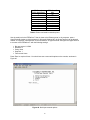
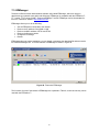
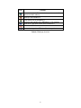
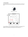
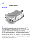
1
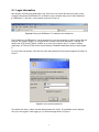
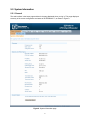
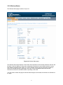
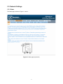
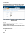
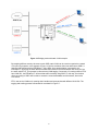
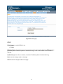
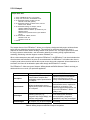
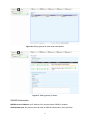
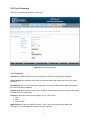
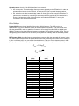
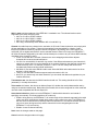
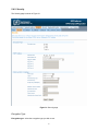
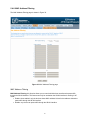
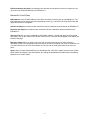
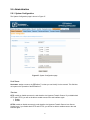
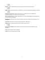
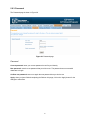
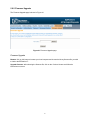
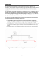
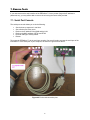
Teletronics EZPlatform™ AP/Hotspot/Repeater User Manual Version 2.0 Firmware 1.0.5.0 or higher © 2008 Teletronics International, Inc Table of Contents 1. Product Overview ........................................................................................................... 3 2. Specifications ..................................................................................................................4 3. Typical Network Configuration ........................................................................................5 4. Hardware Setup and Status LEDs ..................................................................................7 5. Web Interface Configuration ........................................................................................... 8 5.1. Login Information ............................................................................................ 9 5.2. System Information .........................................................................................10 5.2.1. General ........................................................................................... 10 5.2.2. Wireless Status ...............................................................................12 5.3. Network Settings .............................................................................................13 5.3.1. Basic ............................................................................................... 13 5.3.2. DHCP Server .................................................................................. 18 5.3.3. Static Routing ................................................................................. 20 5.3.4. VLAN .............................................................................................. 22 5.3.5. PPPoE ............................................................................................ 26 5.3.6. Firewall ........................................................................................... 28 5.3.7. DDNS ..............................................................................................29 5.3.8. Hotspot ........................................................................................... 31 5.3.9. Port Forwarding .............................................................................. 37 5.4. WLAN1/WLAN2 .............................................................................................. 39 5.4.1. Basic ............................................................................................... 39 5.4.2. Security ...........................................................................................42 5.4.3. AP Settings ..................................................................................... 45 5.4.4. SU Settings (WLAN1 only) ............................................................. 47 5.4.5. Advanced ........................................................................................48 5.4.6. MAC Filtering .................................................................................. 50 5.5. Bandwidth Control .......................................................................................... 52 5.6. Administration ................................................................................................. 54 5.6.1. System Configuration ..................................................................... 54 5.6.2. Administrator Filtering .....................................................................56 5.6.3. Password ........................................................................................ 58 5.6.4. Backup and Restore ....................................................................... 59 5.6.5. Firmware Upgrade .......................................................................... 61 5.7. Log ..................................................................................................................62 5.8. Reboot ............................................................................................................ 63 6. Roaming ......................................................................................................................... 64 7. Rescue Tools ..................................................................................................................65 7.1. Serial Port Console .........................................................................................65 7.2. TELNET .......................................................................................................... 67 7.3. EZManager ..................................................................................................... 68 7.4. Reset Button ................................................................................................... 70 8. Troubleshooting .............................................................................................................. 71 2 1. Product Overview Teletronics' EZPlatform™ AP/Hotspot/Repeater is designed for high-power access point, hotspot and repeater applications. A powerful end-to-end system for a wireless Internet network can be built by integrating the EZPlatform™ with Teletronics TT™ subscriber units and other radios. The simplicity of use of the EZPlatform™ allows operators to quickly bring service to their customers, and with its two serial ports and two Ethernet ports the unit can easily incorporate GPS, GPRS, RFID, VoIP, surveillance cameras, field meters, motion sensors and data networks for multiple industrial and commercial applications. The EZPlatform™ is available in single or dual radio configuration, with 1 W (2.4 GHz) and 600 mW (2.4/5.8 GHz) radio card options. 3 2. Specifications Technical Information Ethernet Networking Wireless Management Security Boot loader Operating system IEEE 802.3 10BASE-T/100BASE-TX with autonegotiation Bridging mode, NAT gateway, static routing, RIPv2 dynamic routing DHCP client, DHCP server Static/dynamic VLAN, IEEE 802.1Q, management VLAN, SSID-based tagging PPPoE, DDNS, STP, QoS (802.11e and WMM), IPv6 802.11a/b/g (2.4/5.8 GHz, 700/900 MHz), turbo mode Four SSIDs per interface, AP/client mode, ad hoc, WDS, roaming WEP, WPA, WPA2 encryption with hex/ASCII keys Adjustable RF TX power and data rate Hotspot: WiFiDog/RADIUS authentication, local/remote captive portal HTTP/HTTPS web configuration interface, TELNET SNMPv2, remote syslog, local event log Bandwidth control with default and host-specific upload/download rates Configuration backup and restore, web-based firmware upgrade Serial port rescue console, EZManager support IP address, MAC address and SSID filtering Firewall, intra-BSS traffic blocking, wireless-wired matching, 802.1X RedBoot Linux, 2.6.x kernel Hardware Specifications CPU Memory Storage Ethernet interface Serial interface Wireless interface LED indicators Power Power consumption Dimensions Weight Operating temperature Enclosure Mounting Intel® Intel IXP425 network processor, 533 MHz 64 MB SDRAM 16 MB flash Two 10BASE-T/100BASE-TX ports Two RS-232 ports Two Mini PCI Type III slots Power, WLAN1 status, WLAN2 status 10-48 V DC PoE (Power over Ethernet) 25 W, maximum 8 x 7.5 x 2.5 in 7 lb -20 °C to +70 °C, non-condensing NEMA 4, ruggedized and weatherproof Wall mount, pole mount 4 3. Typical Network Configuration The wireless interfaces of the EZPlatform™ can be configured in a number of ways, each suited for a particular application or network environment: a) Access Point (AP): this mode allows clients to connect wirelessly to the EZPlatform™ in order to gain access to the network the EZPlatform™ is part of. This is the most widely used mode to provide Internet access to other devices, in either point-to-point or point-to-multipoint fashion. b) Access Point with WDS: in this mode, the EZPlatform™ operates as a wireless switch, relaying information to other WDS-enabled devices. WDS allows great flexibility when building the network, at the cost of possibly reduced throughput. c) Subscriber Unit (SU): also known as bridge, station or client, this mode allows the EZPlatform™ to gain access to a network by connecting to an access point. This AP-SU association is known as infrastructure mode. In the subscriber unit mode, the EZPlatform™ can only be connected to one access point at a time. d) Ad hoc mode: also known as peer-to-peer, this non-hierarchical mode allows clients to communicate with each other directly without the need of an access point. In the EZPlatform™, each of the two wireless interfaces can be configured independently. They can also operate simultaneously regardless of the mode being used in each interface. For example, WLAN1 can be working in subscriber unit mode while WLAN2 is operating as an access point with WDS. Such flexibility makes the EZPlatform™ the ideal choice for a variety of scenarios, as shown in Figures 1 to 3. Figure 1. Access Point, hotspot 5 Figure 2. Repeater, wireless backhaul Figure 3. WDS backhaul with localized wireless service 6 4. Hardware Setup and Status LEDs Hardware Setup Figure 4 shows how to connect the EZPlatform™. Figure 4. Network and power connections The purpose of this setup is to connect the EZPlatform™ so that it can be configured with a computer via the web interface of the EZPlatform™. The power over Ethernet (PoE) module allows you to send/receive data and power the EZPlatform™ with a single cable. When connecting the antennas, care must be taken so that they are properly mounted to avoid mutual interference, especially if both wireless interfaces will be operated in the same 802.11 mode. WLAN1 and WLAN2 are the fixed designations for the two wireless interfaces. WLAN1 is wired to the antenna port that is closer to the hinges of the NEMA 4 enclosure; WLAN2 is wired to the antenna port farther from the hinges of the enclosure (see Section 5.3.1). Status LEDs The behavior of the LEDs mounted on the enclosure is explained in Table 1. LED Position Status Off WLAN1 Left Blinking Solid on Power Center WLAN2 Right Off Solid on Off Blinking Solid on Interpretation Radio card not detected / wireless off No station(s) associated (in AP mode) Not associated to an AP (in SU mode) Station(s) associated (in AP mode) Associated to an AP (in SU mode) Power off Power on Radio card not detected / wireless off No station(s) associated Station(s) associated Table 1. Status LEDs 7 5. Web Interface Configuration The EZPlatform™ can be conveniently configured using its web interface. The web interface can be accessed through a web browser such as Internet Explorer, Mozilla Firebox, Apple Safari, Opera, etc. The web interface provides intuitive navigation and options for you to easily configure the unit. Figure 5 shows a sample page of the web interface. Figure 5. EZPlatform™ web interface Throughout this manual, the buttons on the top row, which are light blue when unselected and orange when selected, will be denominated ‘primary tabs’. Likewise, the buttons immediately below the primary tabs, which are of a darker blue when unselected and orange when selected, will be referred to as ‘secondary tabs’. For instance, in Figure 2 the ‘System Information’ primary tab and the ‘General’ secondary tab are selected. To access a secondary tab, you must first click on the primary tab to which the secondary tab belongs. Each primary tab has a different set of secondary tabs. Some primary tabs do not have secondary tabs. 8 5.1. Login Information After properly connecting and powering the unit, wait for the unit to finish the boot-up process. On the computer connected to the EZPlatform™ via Ethernet, open a browser and point it to the IP address of the EZPlatform™ (192.168.1.124 by default), as shown in Figure 6. Figure 6. Entering the EZPlatform™ IP address in the address bar The IP address of the EZPlatform™ can be changed once you have logged in. In order to access the web interface, the computer needs to be configured for the subnet to which the EZPlatform™ belongs. By default, both HTTP and HTTPS are enabled, so you can log in using the ‘http://’ or ‘https://’ headers, respectively. HTTP and HTTPS access can be enabled or disabled independently after you have logged in. To log in to the web interface, enter the user name and password in the prompt that appears, as shown in Figure 7. Figure 7. User name and password The default user name is ‘admin’ and the default password is ‘admin’. The password can be changed once you have logged in. After logging in, you will see the page shown in Figure 5. 9 5.2. System Information 5.2.1. General The web interface is the home page and thus is the page displayed when you log in. This page displays a summary of the current configuration and status of the EZPlatform™, as shown in Figure 8. Figure 8. System Information page 10 To view details of the Linux operating system, the Linux kernel and network settings, click on the ‘View System Details’ button. The page in Figure 9 will be displayed: Figure 9. System Log Details This page shows a series of commands executed on the Linux kernel, and their corresponding output immediately below each command. 11 5.2.2. Wireless Status The Wireless Status page is shown in Figure 10. Figure 10. Wireless Status page The Wireless Status page displays current status and associations of the wireless interfaces (WLAN1 and WLAN2). Under this page you can see the configuration information for each WLAN interface, such as MAC address, operation mode, SSID, etc. A list of available access points and relevant information is shown if the WLAN interface is operating in SU mode. A list of associated stations and relevant information is shown if the WLAN interface is operating in AP mode. You may need to refresh the page so that the latest changes in the wireless environment are reflected on the page. 12 5.3. Network Settings 5.3.1. Basic The Basic page is shown in Figure 11 and 12. Figure 11. Basic page (top section) 13 Figure 12. Basic page (bottom section) Network Mode The EZPlatform™ has four network interfaces (ETH1, ETH2, WLAN1, WLAN2), as shown in the diagram in Figure 13. WLAN stands for Wireless Local Area Network and should not be confused with WAN (Wide Area Network). 14 Figure 13. Network interfaces of the EZPlatform You can identify the network interfaces as follows: ETH1: Ethernet port farther from the serial ports on the PCB. ETH2: Ethernet port closer to the serial ports on the PCB. WLAN1: Mini PCI slot closer to the Ethernet ports in the PCB, wired to the antenna port closer to the hinges of the enclosure. WLAN2: Mini PCI slot farther from the Ethernet ports in the PCB, wired to the antenna port farther from the hinges of the enclosure. You may need to open the enclosure to have physical access to ETH2. If this is the case (i.e.: your enclosure only has one RJ45 connector), the RJ45 connector of the enclosure should always be connected to ETH1 and you should never select ETH2 for any setting in the EZPlatform™ web interface. Network mode: this is possibly the most important setting in the EZPlatform™ and it should be the first setting you configure. You should choose the appropriate network mode for your network application before configuring any other settings. The network mode dictates how data is passed, forwarded and/or routed among the four network interfaces. Bridging: all interfaces have a common IP address. Outgoing/incoming packets are sent to all interfaces. For example, if data is received by the EZPlatform™ on WLAN2, that data will be sent to ETH1, ETH2, WLAN1 and WLAN2 so that the data is made available to hosts connected to any of the four interfaces. NAT gateway: one interface is designated as WAN and is given its own IP address. The remaining interfaces are collectively referred to as the LAN. The interfaces in the LAN are bridged and have a common IP address. The WAN interface acts as the gateway between the LAN and resources outside the LAN. This network mode is used to enable multiple hosts in the LAN to access a WAN with a single IP address. The most common application of NAT gateway is to provide Internet access to multiple hosts in a private LAN using a single shared public IP address. Static routing: each interface has its own IP address. Routes between interfaces much be added manually. Static routing should only be used by network administrators who have previous experience with static routing. When using static routing, most of the higher layer features of the EZPlatform™ (e.g.: DHCP server, VLAN, PPPoE, DDNS, hotspot) cannot be used. The web interface will warn you if you attempt to enable a feature that cannot be used with static routing. 15 Dynamic routing: each interface has its own IP address. Routes are automatically established and updated using the RIPv2 protocol. Dynamic routing should only be used by network administrators who have previous experience with dynamic routing. When using dynamic routing, most of the higher layer features of the EZPlatform™ (e.g.: DHCP server, VLAN, PPPoE, DDNS, hotspot) cannot be used. The web interface will warn you if you attempt to enable a feature that cannot be used with dynamic routing. Default gateway: when the EZPlatform™ does not know how to route a certain packet, the packet will be sent to the default gateway. The default gateway should be directly accessible by one of the four network interfaces of the EZPlatform™. Preferred DNS server: the server that will perform translation between URLs and IP addresses. Alternate DNS server: the server that will resolve DNS requests if the preferred DNS server is not available. Bridging / NAT Gateway WAN interface: to decide the appropriate selection for your network, see Table 2. What network mode are you using? Will you be using VLAN? No Bridging Yes No NAT gateway Yes WAN interface selection criteria You can ignore the WAN interface setting since packets will be forwarded to all interfaces regardless of your selection. You must assign ETH1 or ETH2 as the WAN interface. The chosen Ethernet interface will act as VLAN trunk, while the other Ethernet interface will not be operational. The WAN interface is the interface that will communicate directly with hosts outside of the LAN of you EZPlatform™. The other three interfaces will sit behind NAT. The WAN interface is the interface that will communicate directly with hosts outside of the LAN of you EZPlatform™. The other three interfaces will sit behind NAT. You must assign ETH1 or ETH2 as the WAN interface but VLAN trunking will not be implemented (see Section 5.3.4). Table 2. WAN interface selection IP address mode: for bridging mode, this refers to the method of assigning an IP address and subnet mask for all four network interfaces. For NAT gateway, this refers to the method of assigning an IP address and subnet mask to the WAN interface. Static: manually configure the IP address and the subnet mask. DHCP client: automatically obtain the IP configuration from a DHCP server. WAN IP address: for bridging mode, this refers to the unique network address that will be assigned to all four network interfaces. For NAT gateway, this refers to the unique network address that will be assigned to the WAN interface. WAN subnet mask: the mask that logically organizes the IP address into its corresponding subnetwork. LAN IP address: (NAT gateway only) the unique network address that will be assigned to the three EZPlatform™ network interfaces that are behind NAT. 16 LAN subnet mask: the mask that logically organizes the IP address into its corresponding subnetwork. Static Routing / Dynamic Routing ETH1 IP address: the unique network address that will be assigned to the ETH1 interface. ETH1 subnet mask: the mask that logically organizes the IP address into its corresponding subnetwork. ETH2 IP address: the unique network address that will be assigned to the ETH2 interface. ETH2 subnet mask: the mask that logically organizes the IP address into its corresponding subnetwork. WLAN1 IP address: the unique network address that will be assigned to the WLAN1 interface. WLAN1 subnet mask: the mask that logically organizes the IP address into its corresponding subnetwork. WLAN2 IP address: the unique network address that will be assigned to the WLAN2 interface. WLAN2 subnet mask: the mask that logically organizes the IP address into its corresponding subnetwork. Save: store the changes made on this page. Cancel: undo the changes made on this page. 17 5.3.2. DHCP Server The DHCP Server page is shown in Figure 14. Figure 14. DHCP Server page DHCP Server DHCP server: for bridging mode, this refers to whether the EZPlatform™ should act as DHCP server and thus automatically configure the IP settings of DHCP clients in the network (all four interfaces). For NAT gateway, this refers to whether the EZPlatform™ should act as DHCP server and thus automatically configure the IP settings of DHCP clients in the LAN (DHCP will not propagate to the WAN). Enable Disable Starting IP address: the first IP address that will be used in the configuration of DHCP clients. Ending IP address: the last IP address that will be used in the configuration of DHCP clients. Subnet mask: the subnet mask that will be used in the configuration of DHCP clients. Default gateway: the default gateway that will be used in the configuration of DHCP clients. Preferred DNS server: the preferred DNS server that will be used in the configuration of DHCP clients. 18 Alternate DNS server: the alternate DNS server that will be used in the configuration of DHCP clients. Lease time (min): the period of time the IP address of a DHCP client will be reserved exclusively for said client. Save: store the changes made on this page. Cancel: undo the changes made on this page. 19 5.3.3. Static Routing Static routing should only be used by network administrators who have previous experience with static routing. When using static routing, most of the higher layer features of the EZPlatform™ (e.g.: DHCP server, VLAN, PPPoE, DDNS, hotspot) cannot be used. The web interface will warn you if you attempt to enable a feature that cannot be used with static routing. The Static Routing page is shown in Figure 15. Figure 15. Static Routing page Static Routing Destination IP address: the destination IP address of an incoming packet. If the destination of an incoming packet matches the destination IP address as well as the subnet mask configured in this page, the routing rule currently being configured will apply. Subnet mask: if the destination of an incoming packet matches the destination IP address as well as the subnet mask, the routing rule currently being configured will apply. Gateway: the IP address of the network device to which the incoming packet should be sent. Interface: the EZPlatform™ network interface from which the packet will be sent out, with the intention of reaching the gateway configured in this page. ETH1 ETH2 WLAN1 WLAN2 Metric: the priority given to the routing rule currently being configured. A lower number represents higher priority. 20 Add new route: store the route currently being configured. You must click on ‘Save’ for the route to take effect. Remove existing route: remove the route selected in the drop-down menu. Save: make all routes take effect. 21 5.3.4. VLAN VLAN Quick Start: 1. Set up VLAN in your wired network 2. Go to Network Settings Æ Basic, and set Network mode: Bridging WAN interface: ETH1 3. Go to Network Settings Æ VLAN, and set VLAN: Enable VLAN type: Static Management VLAN: (a VLAN ID used in your wired network) 4. Go to WLAN1/2 Æ Basic, and set Wireless on/off: On Operation mode: AP 5. Go to WLAN1/2 Æ AP Settings, and map the SSIDs to VLAN IDs in your wired network, as desired 6. Reboot VLANs are Layer 2 constructs that allow you to segregate traffic within an IP subnet. When using VLAN, each Ethernet packet is tagged with a VLAN ID according to the IEEE 802.1Q standard. A VLAN ID is a number between 1 and 4094 that serves to identify to which VLAN a packet belongs. A device in a network can be configured to support certain VLAN IDs. In this way, the device in question will only read the packets whose VLAN ID matches the VLAN ID that it supports, while ignoring all others. The VLAN IDs can be assigned statically (static VLAN) or dynamically (dynamic VLAN). Static VLAN is port-based: traffic going out of a port is always tagged with the same VLAN ID, regardless of the host attached to the port. On the other hand, dynamic VLAN is host-based: the host connected to the network is assigned a VLAN ID based on its MAC address or login information, regardless of the port where the host is attached. Dynamic VLAN is commonly implemented in conjunction with a RADIUS server. Static VLAN can be used with bridging mode or with NAT gateway. The most powerful application of static VLAN is achieved with bridging mode. When using the EZPlatform™ in bridging mode, the purpose of enabling VLAN in the EZPlatform™ is to extend a preexisting wired VLAN network to the wireless environment. Because of this, ETH1 or ETH2 must be chosen as the VLAN trunk (see Section 5.3.1). Each SSID (either primary or secondary) can be statically associated with a VLAN ID. This effectively restricts clients to access only certain resources in the wired network. Figure 16 shows an example of this. 22 Figure 16. Bridging mode with static VLAN example By assigning different security schemes to each SSID, static VLAN can be used to organize the network or for security purposes. In the example of Figure 16, before a wireless client can associate to SSID1, it must first authenticate with the EZPlatform™ using WPA. Once authentication is successful, the EZPlatform™ will tag all the traffic that the wireless client sends to the wired network with VLAN ID 3 as the traffic exits ETH1. This process is referred to as VLAN tagging. Conversely, if incoming traffic to ETH1 has VLAN ID 3, the EZPlatform™ will send that traffic wirelessly using SSID1. In this way, the wireless client connecting to SSID1 will be able to access the customer database and the Internet, but not the CVS server. ETH1 acts as the VLAN trunk, meaning that it handles and sorts packets with different VLAN IDs. The tagging and trunking process is illustrated in more detail in Figure 17. 23 Figure 17. VLAN tagging and trunking for bridging mode with static VLAN On the wired side of the network, traffic is segregated using different VLAN IDs; on the wireless side of the network, traffic is segregated using different SSIDs. What the EZPlatform™ does, in effect, is to translate VLAN IDs to SSIDs, and vice versa, to maintain the traffic segregation. Notice that the wireless client has no knowledge that VLAN is being implemented. Notice also that no special configuration is required in the wireless client. If static VLAN is used with NAT gateway instead, there will be no real VLAN implementation. VLAN trunking will not be applied in the Ethernet interfaces. This means that traffic sent from the wireless network to the wired network will not be tagged with VLAN IDs. Likewise, VLAN-tagged traffic in the wired network will not be able to reach hosts in the wireless network (remember that the wireless network is always untagged). The usefulness of using static VLAN with NAT gateway is to implement a simple isolation of SSIDs for the wireless network: wireless clients connected to SSID1 can only talk to wireless clients connected to SSID2 only if both SSIDs are configured with the same VLAN ID. Keep in mind, however, that the VLAN ID itself (the number) does not mean anything because a real VLAN is not being implemented by the EZPlatform™. Dynamic VLAN is implemented in the same way as static VLAN. The only difference is that the VLAN IDs are not associated to SSIDs. Instead, the VLAN IDs are associated to individual wireless clients. To use dynamic VLAN, 802.1X must be used as the security type for the wireless interfaces and a properlyconfigured RADIUS server is required. The mapping of VLAN IDs to individual hosts should be done in the RADIUS configuration files. The VLAN page is shown in Figure 18. 24 Figure 18. VLAN page VLAN VLAN: whether VLAN should be used or not. If VLAN is enabled, VLAN will be implemented in both wireless interfaces. Enable Disable VLAN type: the method to use to assign VLAN IDs. Static Dynamic Management VLAN: the VLAN ID that hosts must use (in the case of wired hosts) or be associated to (through the corresponding SSID, in the case of wireless hosts) in order to access the EZPlatform™ web interface. You must configure this setting carefully because misconfiguring this setting can lock you out of the EZPlatform™. Save: store the changes made on this page. Cancel: undo the changes made on this page. 25 5.3.5. PPPoE When using NAT gateway, you can dial a PPPoE connection. The hosts behind NAT can use that PPPoE connection initiated by the EZPlatform™ WAN, which acts as PPPoE client. The PPPoE page is shown in Figure 19. Figure 19. PPPoE Routing page PPPoE Connection status: whether there is an active PPPoE connection at the moment. Client IP address: the IP address assigned to the EZPlatform™ by the PPPoE server. Default gateway: the default gateway information given to the EZPlatform™ by the PPPoE server. User name: the user name to use to authenticate with the PPPoE server. Password: the password to use to authenticate with the PPPoE server. Connection mode: how to initiate and terminate the PPPoE connection as a result of inactivity On demand: the connection will be terminated after the period of inactivity specified in the ‘Idle timeout (min)’ setting. Keep alive: keep the connection alive even when it is not in use. This is accomplished by redialing periodically as specified by the ‘Redial period (s)’ setting. Idle timeout (min): the number of minutes of inactivity after which the PPPoE connection will be terminated. 26 Redial period (s): how often, in seconds, to redial the connection in order to keep it alive. Connect: dial the connection using the specified parameters. Disconnect: terminate the current PPPoE connection. 27 5.3.6. Firewall The Firewall page is shown in Figure 20. Figure 20. Firewall page Firewall Firewall: whether to enable the firewall or not. Enable Disable Save: store the changes made on this page. Cancel: undo the changes made on this page. 28 5.3.7. DDNS DDNS (Dynamic DNS) allows you to keep a URL mapped to the IP address of the EZPlatform™ even if said IP address changes. For this to be possible, the EZPlatform™ must have access to the Internet and have a public IP address. Alternatively, you can put the EZPlatform™ behind a router (NAT gateway) and configure port forwarding in the router so that port 80 (HTTP) is forwarded to the EZPlatform™, in order to make the web interface of the EZPlatform™ accessible from the Internet. The DDNS feature of the EZPlatform™ is designed to work with the DDNS implementation of freedns.afraid.org. A DDNS certificate (an alphanumeric string) issued by freedns.afraid.org will allow the EZPlatform™ to periodically send IP address updates to freedns.afraid.org in case the IP address of your EZPlatform™ changes. You can register a URL (subdomain) and obtain a DDNS certificate for free at http://freedns.afraid.org. To do so, follow these steps: 1. 2. 3. 4. 5. 6. 7. 8. Open a web browser and type http://freedns.afraid.org in the address bar. On the bottom of the page, click on ‘Sign Up!’. Fill in the text boxes and click on ‘Send activation email’. Login to the email account provided to afraid.org and click on the activation URL. Go to http://freedns.afraid.org again. Click on ‘Dynamic DNS’ on the left frame. Click on ’add one’. Add a new subdomain as shown in Figure 21. For ‘Type’, choose ‘A’. The subdomain and the domain can be anything of your choice. Do not worry about the destination. When you are done, click on ‘Save!’. Figure 21. Registration of a subdomain at freedns.afraid.org 9. Click on ‘Dynamic DNS’ on the left frame. 10. Click on ‘Direct URL’. Look at your web browser address bar. In the browser address bar, copy everything that comes after the ‘?’ sign, as shown in Figure 22. This is the DDNS certificate you need to set up DDNS on the EZPlatform™. Figure 22. Obtaining the DDNS certificate The DDNS page is shown in Figure 23. 29 Figure 23. DDNS page DDNS DDNS: whether to enable DDNS or not. Enable Disable DDNS certificate: the alphanumeric string issued by freedns.afraid.org that allows the EZPlatform™ to periodically send IP address updates to freedns.afraid.org in case the IP address of the EZPlatform™ changes. Update time (s): how often, in seconds, to send an IP address update to freedns.afraid.org Save: store the changes made on this page. Cancel: undo the changes made on this page. 30 5.3.8. Hotspot Hotspot Quick Start: 1. Set up a RADIUS server in your network 2. Set up user accounts in the RADIUS server 3. Go to Network Settings Æ Basic, and set Network mode: NAT gateway 4. Go to Network Settings Æ DHCP Server, and set DHCP server: Enable 5. Go to Network Settings Æ Hotspot, and set Hotspot: RADIUS authentication RADIUS server IP address: (IP address of your RADIUS server) Shared secret: (shared secret of your RADIUS server) 6. Go to WLAN1/2 Æ Basic, and set: Wireless on/off: On Operation mode: AP 7. Reboot The hotspot feature of the EZPlatform™ allows you to display a designated web page to wireless clients before they are allowed to access the Internet. This web page is called the captive portal, since it captures all outbound traffic before deciding whether to let it pass or not. The captive portal can be used for many purposes: authentication, user information gathering, accounting, billing, legal disclaimers, marketing, advertising, technical support, customer feedback, etc. When a client attempts to pass traffic through the EZPlatform™, the EZPlatform™ can check whether that client has been authenticated. If the client is not authenticated, the EZPlatform™ will redirect the client to a captive portal, where the client will be able to enter a user name and a password. After authentication is successful, the client will be allowed to pass traffic through the EZPlatform™ normally. The EZPlatform™ offers two types of hotspot: Wifidog-based and RADIUS-based. Table 3 can help you decide which one to use for your particular application: Description Requirements Advantages Disadvantages Wifidog-based Wifidog is an open source project that provides a complete and embeddable captive portal solution for hotspots Wifidog (authentication server + captive portal) needs to be installed on a computer Highly customizable captive portal, interesting features (e.g.: integration with Google Maps), web interface configuration Installation and configuration can be complex, only for open hotspots RADIUS-based RADIUS (Remote Authentication Dial In User Service ) is a very widely used authentication protocol RADIUS, which acts as the authentication server, needs to be installed on a computer. The captive portal has already been set up on the EZPlatform™ and is ready to use. Popularity of RADIUS, high control over authentication attributes, accounting/billing integration capabilities, very easy to configure Captive portal not as customizable as Wifidog Table 3. Wifidog hotspot and RADIUS hotspot comparison 31 Before configuring either type of hotspot in the EZPlatform™, you should first have a computer with either Wifidog or RADIUS already installed, configured and running, with the user accounts already set up. For information, installation, configuration and support for Wifidog, visit http://dev.wifidog.org. There are several sources from which you can install a RADIUS server. Some of them are commercial, while others are open source. Among the open source options is FreeRADIUS (http://freeradius.org). To use the hotspot, you must set the EZPlatform™ to NAT gateway mode, and the Wifidog server or the RADIUS server should be placed on the WAN side of the EZPlatform™. For wireless clients to access the hotspot, WLAN1 and/or WLAN2 must be operating in AP mode. You may want to enable the DHCP server of the EZPlatform™ so that it can provide DHCP service to the wireless clients in the LAN. The Hotspot page is shown in Figure 24 and 25. Figure 24. Hotspot page (top section) 32 Figure 25. Hotspot page (bottom section) Hotspot Hotspot: the hotspot spot type to use. Disable Wifidog authentication RADIUS authentication Wifidog Authentication Wifidog server IP address: the IP address of the computer where Wifidog is installed. Gateway ID: the name that identifies the Wifidog node. The gateway ID can be found in the Wifidog web interface (Node administration Æ Edit node), as shown in Figures 26 and 27. 33 Figure 26. Wifidog gateway ID under Node administration Figure 27. Wifidog gateway ID details RADIUS Authentication RADIUS server IP address: the IP address of the computer where RADIUS is installed. Authentication port: the port that should be used for RADIUS authentication (1812 by default). 34 Accounting port: the port that should be used for RADIUS accounting (1813 by default). Shared secret: the password that the EZPlatform™ needs to give the RADIUS server in order for the RADIUS server to authorize the EZPlatform™ to act as NAS (Network Access Server). Authentication timeout (min): the time in minutes that the EZPlatform™ is authorized to act as a NAS of the RADIUS server. This setting is usually not critical. Captive portal title: the title to be displayed in the captive portal, as shown in Figure 28. The following HTML tags are allowed: <br>, <i></i> and <u></u>. Captive portal text: the text to be displayed in the captive portal, as shown in Figure 28. Do not press the Enter key while typing inside this text box. Use the HTML tag <br> instead. The following HTML tags are allowed: <br>, <b></b>, <i></i>, <u></u>, <tr></tr>, <td></td>, <img> (the image must belong to one of the walled garden sites) and <a></a> (the link target must belong to one of the walled garden sites). Figure 28. Captive portal of the RADIUS-based hotspot SMTP redirection: use a specific SMTP server for outgoing mail instead of the SMTP server requested by the user. The usefulness of SMTP redirection is that some ISPs so not allow their customers to send mail if they are not directly connected to the ISP network, so SMTP redirection allows clients to send outgoing mail using an SMTP server that is known to accept and deliver mail for the clients. Enable Disable SMTP server IP address: the IP address of the SMTP server to use for outgoing mail. 35 Walled garden site 1-5 (first line): the designated websites within the walled garden can be visited by clients without them having to authenticate. Some websites have elements that reference other websites, so their contents might not display correctly. The first line in each walled garden configuration is the hyperlink label that will be displayed in the captive portal. Walled garden site 1-5 (second line): the URL of the website to include in the walled garden. Save: store the changes made on this page. Cancel: undo the changes made on this page. 36 5.3.9. Port Forwarding The Port Forwarding page is shown in Figure 29. Figure 29. Port Forwarding page Port Forwarding Nickname: any name or phrase to help you identify the rule that is currently being configured. LAN IP address: the destination host within the LAN where traffic that matches the current rule will be forwarded. LAN start port: the port of the destination host specified in ‘LAN IP address‘ where traffic that matches the current rule will be forwarded. LAN end port: allows specify a range of ports, if desired. If only one port is desired, configure this setting to be the same as ‘LAN end port’. Protocol: whether the current rule should apply to TCP, UDP or both. TCP UDP TCP and UDP WAN map port: the port of the WAN to monitor. Traffic coming into this port of the WAN of the EZPlatform™ will be forwarded to the specified host in the LAN. 37 Add new rule: store the rule currently being configured. Remove existing rule: delete the rule currently selected in the drop-down menu. Save: make all the port forwarding rules effective now. 38 5.4. WLAN1/WLAN2 WLAN1 and WLAN2 are the fixed designations for the two EZPlatform™ wireless interfaces. WLAN1 is the radio card closer to the Ethernet ports and WLAN2 is the radio card farther from the Ethernet ports, as explained in Section 5.3.1. The configuration pages of WLAN1 and WLAN2 are identical, with the exception that WLAN2 cannot be used in SU mode. 5.4.1. Basic The LAN page is shown in Figure 30. Figure 30. Basic page Operation Mode Wireless on/off: whether to use the WLAN interface or not. On: enable the WLAN interface. Off: disable the WLAN interface. 39 Operation mode: the role of the WLAN interface in the network. AP: access point. This mode allows clients to connect wirelessly to the EZPlatform™ in order to gain access to the network the EZPlatform™ is part of. This is the most widely used mode to provide Internet access to other devices, in either point-to-point or point-to-multipoint fashion. SU: subscriber unit (also know as bridge, station or client). This mode allows the EZPlatform™ to gain access to a network by connecting to an access point. The resulting AP-SU association is known as infrastructure mode. In the subscriber unit mode, the EZPlatform™ can only be connected to one access point at a time. Basic Settings Primary SSID: the service set identifier of the primary WLAN interface. The SSID can be any alphanumeric string of 32 characters or less (do not use spaces or symbols). An AP and an SU must have the same SSID in order to establish a connection. Never assign the same SSID to WLAN1 and WLAN2. There is no functional difference between the primary SSID and the secondary SSIDs. The only distinguishing factor between the two is that the primary SSID is mandatory while the secondary SSIDs are optional. RF TX power (dBm): the radio frequency transmission power at which the radio card will operate, in dBm. The value entered must be within the specifications of the radio card being used. Power can be measured in dBm or milliwatts (mW). You can use the formulas below or Table 4 to convert between power in dBm (PdBm) and power in milliwatts (PmW). 1 Watt is equivalent to 1000 milliwatts (i.e., 1 W = 1000 mW). PdBm = 10 log PmW PmW = 10 Power in dBm (dBm) 0 1 2 3 4 5 6 7 8 9 10 11 12 13 14 15 16 17 18 19 20 21 22 PdBm 10 Power in milliwatts (mW) 1.0 1.3 1.6 2.0 2.5 3.2 4.0 5.0 6.3 7.9 10 13 16 20 25 32 40 50 63 79 100 126 159 40 23 24 25 26 27 28 29 30 200 250 320 400 500 630 800 1000 Table 4. dBm-W power conversion table 802.11 mode: which amendment of the IEEE 802.11 standard to use. The selected mode must be supported by the radio card being used. 802.11a: 5.8 GHz, OFDM, 54 Mbps. 802.11b: 2.4 GHz, DSSS, 11 Mbps. 802.11g: 2.4 GHz, OFDM, 54 Mbps. 802.11b/g: automatically switch between 802.11b and 802.11g. Channel: the radio frequency channel to be used when in AP mode. Channel selection must comply with all laws applicable to your location. Teletronics International is not responsible for violation of radio frequency regulations caused by improper channel configuration. By clicking on the 'Save' button you certify that you are legally authorized to use the selected channel. When in SU mode, the EZPlatform™ will scan all channels supported by the radio card and attempt to connect to any AP whose SSID matches, regardless of the channel it is using. 5 GHz: for use with 802.11a mode. Channels are non-overlapping and therefore adjacent channels will not cause mutual interference. 2.4 GHz: for use with 802.11b and 802.11g modes. If the difference between any two channels is equal to or greater than 5, then the channels do not overlap. Otherwise, the channels overlap and interference may occur. For example, channels 1, 6 and 11 do not overlap and can be used simultaneously without causing mutual interference. 900 MHz: for use with some 900 MHz radio cards. Other 900 MHz radio cards need to be driven with the 2.4 GHz channels. Turbo: for use with radio cards that support static turbo mode in 802.11a. Non-FCC: you should only use these channels if you are certain that laws and regulations in your location allow them. Transmission rate: the data rate the WLAN interface should use. This setting should be left in ‘Best (automatic)’ in virtually all scenarios. Turbo mode: this feature, also known as Atheros Super AG, doubles the nominal data transfer rate by using two channels simultaneously. Both sides of the wireless link must be configured for turbo mode and use radio cards compatible with Atheros Super AG. Auto channel selection: whether to let the EZPlatform™ decide which channel to use instead of specifying one manually. This feature applies to AP mode only. Enable: during boot-up, the EZPlatform™ will scan through all the channels supported by the radio card to see which channels are already being used by other radios in the area. The EZPlatform™ will then select a channel that is relatively clean from interference. The channel selection process only occurs once (during boot time) and the channel will not be changed again once the EZPlatform™ is up and running. Disable: choose a channel manually. Save: store the changes made on this page. Cancel: undo the changes made on this page. 41 5.4.2. Security The Security page is shown in Figure 31. Figure 31. Security page Encryption Type Encryption type: select the encryption type you wish to use. 42 None: no encryption. WEP: Wired Equivalent Privacy, a deprecated algorithm proven to have serious weaknesses. WPA: Wi-Fi Protected Access, IEEE 802.11i. 802.1X: an IEEE standard for network access control. Under this framework, an authenticator (the EZPlatform) communicates with an authentication server (RADIUS server) to determine whether a supplicant (wireless client) should be granted access to the network based on the credentials provided by the supplicant. 802.1X can be thought of as a way of extending RADIUS to the wireless realm. When using 802.1X, the EZPlatform™ supports PEAP and TTLS authentication. For either authentication type to work, the RADIUS server and the wireless clients must support the authentication method in question and be properly configured. As far as the wireless clients are concerned, PEAP is supported natively in Windows XP, while TTLS requires installation of third party software. One such implementation of TTLS is SecureW2, which can be downloaded for free from http://www.securew2.com. WEP Settings Authentication: select the WEP authentication type. Open: stations are always automatically authenticated and associated, but cannot pass traffic if they do not have a matching WEP key. Shared: stations need to have the same WEP key as the AP to be authenticated. Shared authentication is considered a security risk beacuse the encryption scheme is sent over the air during the authentication negotiation process, making it easier for a hacker to discover the WEP key. Default WEP key: data received is decrypted using any of the four WEP keys, but data transmitted is encrypted using the default WEP key only. WEP key 1 WEP key 2 WEP key 3 WEP key 4 WEP key length: whether to use a 64-bit or a 128-bit key. A longer key is considered to be more robust. Keys may be entered as ASCII (0-9, a-z, A-Z, symbols) or hexadecimal (0-9, a-f/A-F) characters. 64 bits (5 ASCII characters) 64 bits (10 hexadecimal characters) 128 bits (13 ASCII characters) 128 bits (26 hexadecimal characters) WEP key 1-4: enter the WEP key to be used. The key must be of the same length as specified in ‘WEP key length’. WPA Settings WPA mode: select which WPA mode should be used WPA: released before the completion of the IEEE 802.11i standard and specifically designed to work with pre-WPA wireless network cards. WPA2: implements the full 802.11i standard but may not work with some older network cards. WPA and WPA2 Cipher: the specific algorithm for performing encryption and decryption TKIP: Temporal Key Integrity Protocol AES: Advanced Encryption Standard TKIP and AES Pre-shared key type: the method to use to enter the pre-shared key. 43 8-63 ASCII characters (0-9, a-z, A-Z, symbols) 64 hexadecimal characters (0-9, a-f/A-F) Pre-shared key: the password to be used for WPA. Group rekey interval (sec): how often, in seconds, to automatically renew the encryption keys that the AP and the SU use, for security purposes. RADIUS server IP address: the IP address of the RADIUS server to which the EZPlatform™ should talk to perform 802.1X authentication. Authentication port: the port that should be used for RADIUS authentication (1812 by default). Accounting port: the port that should be used for RADIUS accounting (1813 by default). Shared secret: the password that the EZPlatform™ needs to give the RADIUS server in order for the RADIUS server to authorize the EZPlatform™ to act as NAS (Network Access Server). Authentication timeout (min): the time in minutes that the EZPlatform™ is authorized to act as a NAS of the RADIUS server. This setting is usually not critical. Save: store the changes made on this page. Cancel: undo the changes made on this page. 44 5.4.3. AP Settings The configuration in AP Settings will only be applied when the WLAN interface is being used in AP mode. If SU mode is used, the configuration in AP Settings will not be used, but it will be retained nonetheless. The AP Settings page is shown in Figure 32. Figure 32. AP Settings page Basic Settings Primary SSID: the service set identifier of the primary WLAN interface. The SSID can be any alphanumeric string of 32 characters or less (do not use spaces or symbols). An AP and an SU must have the same SSID in order to establish a connection. Never assign the same SSID to WLAN1 and WLAN2. There is no functional difference between the primary SSID and the secondary SSIDs. The only 45 distinguishing factor between the two is that the primary SSID is mandatory while the secondary SSIDs are optional. Broadcast SSID: whether to broadcast the SSID of the AP over the air for all clients to know of its presence. If the SSID is not broadcast, clients must know the SSID of the AP beforehand and specifically request to be connected with that SSID; otherwise, they will not be able to connect. Not broadcasting the SSID should not be relied on as the only security measure. Yes No VLAN ID: when using static VLAN, each active SSID can be associated to a VLAN ID (see Section 5.3.4). SSIDs associated to with different VLAN IDs will be isolated from each other. Security: each SSID can have its own security settings. WDS WDS: with WDS (Wireless Distribution System), the WLAN interface operates as a wireless Layer 2 switch, relaying information to other WDS-enabled devices. WDS allows great flexibility when building the network, at the cost of possibly reduced throughput. WDS and WPA are incompatible, so these two features should not be used at the same time. When using WDS, all WDS stations must use the same channel and different SSIDs. Secondary SSIDs are not supported when using WDS. Enable Disable AP MAC address 1-6: specify the MAC addresses of the WDS-enabled access points to which you wish to relay data. MAC addresses must be entered as octets separated by colons (e.g.: 00:60:B3:F8:C6:D4). Both lower and upper case letters are acceptable. The EZPlatform™ will only communicate with those WDS stations whose MAC address is entered here. Intra-BSS Traffic Blocking Intra-BSS Traffic Blocking: the BSS (Basic Service Set) is the name given to an AP and all its associated clients. Intra-BSS traffic blocking is a security measure that prevents clients connected to the same AP from talking to each other. When Intra-BSS traffic blocking is enabled, clients can only communicate with the AP. Cient-to-client communication is not permitted. Enable Disable Save: store the changes made on this page. Cancel: undo the changes made on this page. 46 5.4.4. SU Settings (WLAN1 only) Only WLAN1 has the SU Settings secondary tab, since WLAN2 cannot operate in SU mode. The configuration in SU Settings will only be applied when the WLAN1 interface is being used in SU mode. If AP mode is used, the configuration in SU Settings will not be used, but it will be retained nonetheless. The SU Settings page is shown in Figure 33. Figure 33. SU Settings page Basic Settings Wireless mode: choose the wireless mode to be used with the SU mode Infrastructure: for AP-SU hierarchical links Ad hoc: peer-to-peer mode. This is a non-hierarchical direct communication mode between SUs, where an AP is not required. BSSID: if a client sees two APs with the same SSID, there will be some ambiguity as to which AP the client should select to establish a connection. Specifying the BSSID (the MAC address of the desired AP) resolves such ambiguity. Both SSID and BSSID must match for a wireless link to be established. The BSSID must be entered as octets separated by colons (e.g.: 00:60:B3:F8:C6:D4). Both lower and upper case letters are acceptable. Save: store the changes made on this page. Cancel: undo the changes made on this page. 47 5.4.5. Advanced The settings on this page should only be manipulated by advanced wireless network administrators. Misconfiguration of the settings on this page may result in degraded performance. The Advanced page is shown in Figure 34. Figure 34. Advanced page Wireless-Wired Matching Wireless-wired matching: whether the wireless interface should be turned off immediately if no wired network connection is detected (i.e., ETH1 and ETH2 not connected to a network). This feature also works when the Net side of the PoE power injector is disconnected. The wireless interface will be turned on again when a network connection is detected at ETH1 or ETH2. Enable Disable Packet Settings Packet fragmentation: whether packets should be fragmented if they exceed the size specified in ‘Fragmentation threshold (bytes)’. Enable Disable Fragmentation threshold (bytes): the maximum allowed size of packets to be transmitted. If a packet exceeds this threshold, it will be fragmented into smaller packets. 48 RTS: whether packets should be transmitted using the RTS/CTS protocol if they exceed the size specified in ‘RTS threshold (bytes)’. Enable Disable RTS threshold (bytes): packets whose size exceeds this threshold will be transmitted using the RTS/CTS protocol. Beacon period (ms): the interval at which a unit in ad hoc mode sends beacons to nearby wireless devices to indicate its presence. This option is only applicable when ad hoc mode is selected. DTIM interval (beacons): how often (every how many beacons) to include a DTIM (Delivery Traffic Indication Message) with the AP beacon. This option is only applicable when AP mode is selected. Save: store the changes made on this page. Cancel: undo the changes made on this page. 49 5.4.6. MAC Address Filtering The MAC Address Filtering page is shown in Figure 35. Figure 35. MAC Address Filtering page MAC Address Filtering MAC Address Filtering: this function allows you to control which devices are allowed to pass traffic through the WLAN interface. This feature can only be used when the WLAN interface is working in AP mode. Enable: when enabled, only the devices whose MAC address is listed in the table are allowed to pass traffic through the WLAN interface Disable: any device can pass traffic through the WLAN interface 50 MAC Address: enter the MAC address of the device you wish to authorize to have access to the WLAN interface. The MAC address must be entered as octets separated by colons (e.g.: 00:60:B3:F8:C6:D4). Both lower and upper case letters are acceptable. Nickname: here you can enter a note to remind yourself what device or location corresponds to the MAC address entered. This field is provided for your convenience and has no impact on the operation of the EZPlatform™. Save: store the changes made on this page. Cancel: undo the changes made on this page. 51 5.5. Bandwidth Control Bandwidth control allows you to limit the rate at which devices can upload to or download from the EZPlatform™. The Bandwidth Control page is shown in Figure 36. Figure 36. Bandwidth Control page This feature allows you to set specific upload and download rates for the devices you specify. If you want to completely prevent a device from passing any traffic through the EZPlatform™, you can assign its data rates to zero. On the other hand, if you want to assign no restrictions whatsoever to a particular device, assign it a very high data rate such as 60000 kbps Basic Settings Bandwidth control: choose whether you want to enable bandwidth control. Enable: when you enable bandwidth control, you must specify a default upload rate and a default download rate for those devices that do not have an explicit rule set up for them, i.e. for devices whose MAC address does not appear in the table at the bottom of the page. Typically, you will want the default rates to be lower than the rates of the explicitly defined rules. This way, if a device has an explicitly defined rule, you should think of it as privileged. That is to say, the table at the bottom of the page is a white list, not a black list. Disable: no bandwidth limit rules apply for any device connected to the EZPlatform™. Default upload rate (kbps): the maximum rate at which devices that do not have an explicit rule set up for them can upload data to the EZPlatform™. 52 Default download rate (kbps): the maximum rate at which devices that do not have an explicit rule set up for them can download data from the EZPlatform™. Bandwidth Control Rules MAC address: enter the MAC address of the device for which you wish to set up a bandwidth rule. The MAC address must be entered as octets separated by colons (e.g.: 00:60:B3:F8:C6:D4). Both lower and upper case letters are acceptable. Upload rate (kbps): the maximum rate at which the device is allowed to upload data to the EZPlatform™. Download rate (kbps): the maximum rate at which the device is allowed to download data from the EZPlatform™. Add new rule: after you have completed the fields ‘MAC address’, ‘Upload rate (kbps)’ and ‘Download rate (kbps)’, click on the ‘Add new rule’ button to save the rule. The new rule will appear in the table at the bottom of the page. Remove existing rule: if you wish to remove a rule you have previously set up, select it from the ‘Bandwidth control’ rules drop-down menu and click on the ‘Remove existing rule’ button to delete the rule. You cannot edit a rule: you will have to delete the rule you wish to modify and create a new one in its place. Apply: when you have finished defining your bandwidth rules, click on the ‘Apply’ button for them to take effect. Unlike most pages in the web interface, the settings for bandwidth control take effect immediately and there is no need to reboot. 53 5.6. Administration 5.6.1. System Configuration The System Configuration page is shown in Figure 37. Figure 37. System Configuration page Host Name Host name: assign a name to the EZPlatform™ so that you can identify it in the network. This field has no impact on the operation of the EZPlatform™. Services HTTP: enable or disable access to the web interface via Hypertext Transfer Protocol. If you disable both HTTP and HTTPS, you will not be able to enable access to the web interface again. Enable Disable HTTPS: enable or disable access to the web interface via Hypertext Transfer Protocol over Secure Socket Layer. If you disable both HTTP and HTTPS, you will not be able to enable access to the web interface again. 54 Enable Disable TELNET: enable or disable access to the web interface via Telecommunication Network. Enable Disable SNMP: enable or disable monitoring of the EZPlatform™ using the Simple Network Management Protocol. Enable Disable Read community string: the password that allows you to perform queries to the EZPlatform™ (snmpwalk, snmpget, etc) to retrieve monitoring information. Write community string: the password that allows you to write to MIBs (Management Information Base) via commands such as snmpset. sysContact: the OID that contains contact information of the person or organization responsible for the EZPlatform™. sysLocation: the OID that contains the physical location of the EZPlatform™. syslog: enable or disable forwarding of system events to a syslog server. Enable Disable syslog server IP address: the IP address of the server that will receive event messages from the EZPlatform™. Save: store the changes made on this page. Cancel: undo the changes made on this page. 55 5.6.2. Administrator Filtering The Admin IP Filter page is shown in Figure 38. Figure 38. Admin IP filter page SSID Filtering SSID filtering: whether to grant access to the web configuration of the EZPlatform™ only to specific SSIDs or to any SSID. Because each SSID can have its own security settings, you can assign a specific administrator password for the SSID to be designated as authorized SSID. Enable Disable Authorized SSID: the SSIDs that will be allowed to access the web interface and change the configuration of the EZPlatform™. IP Address Filtering Administrator IP address filtering is a security feature that allows you to restrict who is authorized to access the web interface and change the configuration of the EZPlatform™. When one or more filters have been set up, only the specified IP addresses will be allowed to access the web interface. IP address: the IP address of the device you wish to grant access to the web interface. Subnet mask: the subnet mask to be applied to the IP address. A subnet mask of 255.255.255.255 should be used for single hosts. 56 Nickname: a name of phrase to help you identify the rule currently being configured. Add new filter: after you have completed the ‘IP address’ and ‘Subnet mask’ fields, click on the ‘Add new filter’ button to add assign administrator privileges to the designated IP address. The new filter appears in the table at the bottom of the page. Remove existing filter: to remove previously assigned administrator privileges from an IP address, choose the corresponding device in the drop-down menu and click on the ‘Remove existing filter’ button. Apply: make the settings on this page take effect. 57 5.6.3. Password The Password page is shown in Figure 39. Figure 39. Password page Password Current password: enter your current password to confirm your identity. New password: enter the new password that you wish to use. The password must not exceed 8 characters in length. Confirm new password: enter once again the new password that you wish to use Apply: when you have finished completing the fields on this page, click on the ‘Apply’ button for the changes to take effect. 58 5.6.4. Backup and Restore The Backup and Restore page is shown in Figure 40. Figure 40. Backup and Restore page System Backup Download configuration file: click on this link to download the current configuration of the EZPlatform™ to your computer so that you can restore it later if needed. System Restore From local computer: use this option if the configuration file which contains the settings that you wish to restore is located in your local computer. From HTTP or FTP server: use this option if the configuration file which contains the settings that you wish to restore is located in a HTTP or FTP server. Continue: click on ‘Continue’ after you have selected the system restore method. 59 System Restore Reset all settings to default: click on this button to restore all the settings of the EZPlatform™ to factory default, including the IP address. 60 5.6.5. Firmware Upgrade The Firmware Upgrade page is shown in Figure 41. Figure 41. Firmware Upgrade page Firmware Upgrade Browse: click on this button to browse your local computer and choose the binary firmware file you wish to load to the EZPlatform™. Upgrade firmware: after selecting the firmware file, click on the ‘Continue’ button and follow the instructions on screen. 61 5.7. Log The Log page is shown in Figure 42. Figure 42. Log page This page shows you important events that have been logged by the EZPlatform™. Events are displayed chronologically, with the most recent ones displayed at the bottom of the list. 62 5.8. Reboot The Reboot page is shown in Figure 43. Figure 43. Reboot page Reboot: reboot the EZPlatform™. Continue: make more configuration changes. You should remember to reboot the EZPlatform™ after you have finished changing all the settings you need. 63 6. Roaming The roaming feature of the EZPlatform™ allows wireless clients to roam from EZPlatform™ to EZPlatform™ without losing the connection in the data link layer and possibly without interrupting traffic in the network layer, depending on the specific network protocol being used. Clients do not need to manually re-associate or re-authenticate when they switch EZPlatforms; this switchover is handled automatically. The roaming speed achievable with the EZPlatform™ is at least 5 mph (8 km/h). Higher speeds might be achievable but are not guaranteed. The switching process can last up to 5 seconds, during which traffic may be lost. The following protocols have been tested successfully for roaming: HTTP, FTP, ICMP and OSCAR (AOL’s AIM instant messaging protocol). Roaming is supported in bridging mode and also in NAT gateway mode. The EZPlatforms involved in roaming can use different DHCP schemes, different channels and even different 802.11 modes. The roaming function is always enabled; it does not need to be manually activated in the web interface. However, some settings must be configured in specific ways: To allow a client to roam from an EZPlatform™ to another, the EZPlatforms must have an overlapping RF zone, but they must not be able to see each other, as shown in Figure 44. To verify this, turn on EZP1, turn off EZP2, put a wireless client in the physical location of EZP2 and scan for APs. The wireless client should not see EZP1. Repeat, reversing EZP1 and EZP2. In each EZPlatform™, the wireless interface that will be used for roaming must be in AP mode and use 802.1X. All EZPlatforms must be configured to use the same RADIUS server in their 802.1X settings. All wireless interfaces of the EZPlatforms that will be used for roaming must use the same SSID. Figure 44. EZP1 and EZP2 have an overlapping RF zone but cannot see each other 64 7. Rescue Tools If you cannot access the web interface of the EZPlatform™ for any reason (forgot the IP address or password, etc), you may still be able to recover the unit using the rescue tools provided. 7.1. Serial Port Console The serial port console allows you to do the following: See the boot-up sequence in real-time See critical errors if they occur Retrieve the IP address of the WAN and the LAN Retrieve the MAC address of ETH1 and ETH2 Reset all settings to factory default Reboot To access the EZPlatform™ via the serial port console, first you will need to connect the serial port of the EZPlatform™ to the serial port of your computer, as shown in Figure 45 and Table 5. Figure 45. End-to-end connection pins 65 DB9 Female (To PC Serial Port) 1 2 3 4 5 6 7 8 9 EZPlatform™ SP1 n/c 5 2 n/c 3 n/c 1 4 n/c Table 5. End-to-end serial connection pinout Use the serial port in the EZPlatform™ that is closer to the Ethernet ports. In the computer, open a HyperTerminal window or similar program. In Microsoft Windows XP, the HyperTerminal can be located at Start Æ Programs Æ Accessories Æ Communications Æ HyperTerminal. Configure the HyperTerminal to connect to the EZPlatform™ with the following settings: Bits per second: 115200 Data bits: 8 Parity: None Stop bits: 1 Flow control: None Press ‘Enter’ a couple of times. You should now see a menu with options on the console, as shown in Figure 46. Figure 46. Serial port console options 66 7.2. TELNET With TELNET you can do the following: Retrieve the MAC address of ETH1 and ETH2 Reset all settings to factory default Reboot To access the EZPlatform™ via TELNET, open a terminal or command prompt. In Microsoft Windows XP, you can open a command prompt window by going to Start Æ Programs Æ Accessories Æ Command Prompt. Type ‘telnet <IP address>’, substituting ‘<IP address>’ for the actual IP address of the EZPlatform™ (e.g.: telnet 192.168.1.124). After the connection has been established, enter your user name and password. You should now see a menu with options on the console, as shown in Figure 47. These options are identical to those in the serial port console. Figure 47. TELNET options 67 7.3. EZManager Teletronics offers a network administration software utility called EZManager, which can help you administrate your network more easily and effectively. EZManager is compatible with the EZPlatform™, TT™ series, TTX™ series, SLAB™ series and EZBridge™ series. EZManager can be downloaded for free from Teletronics’ website, www.teletronics.com. EZManager allows you to do the following: See all EZPlatforms connected to the network Retrieve the IP address of the WAN or LAN Retrieve the MAC address of ETH1 and ETH2 Retrieve the firmware version Change the IP settings Reboot EZManager does not require installation; you can simple uncompress the download file and execute the file called ‘EZManager.exe’. The main interface of EZManager is shown in Figure 48. Figure 48. Teletronics EZManager The functions of some of the buttons in EZManager are explained in Table 6, as well as how they can be used with the EZPlatform™. 68 Icon Function Scans the network for Teletronics devices and shows their IP address and MAC address. Allows you to change the IP address, subnet mask and default gateway of the EZPlatform™ Loads firmware to the EZPlatform™ Opens the web interface of the EZPlatform™. The computer needs to be in the same subnet as the EZPlatform™ Reboots the EZPlatform™ Resets all settings of the EZPlatform™ to factory default Table 6. EZManager functions 69 7.4. Reset Button With the reset button you can restore the EZPlatform™ to its factory default settings. The reset button is a push-button that is located in one of the corners of the PCB, near the serial ports, as shown in Figure 49 and 50. Figure 49. Reset push-button Figure 50. Location of the reset button on the PCB To reset the EZPlatform™ to factory default settings, power the EZPlatform™ and wait until it has finished booting up. Press the reset button for 10 seconds and then release the button. This causes the EZPlatform™ to be restored to factory default settings and to reboot immediately after. 70 8. Troubleshooting 1. What is the default IP address, user name and password of the EZPlatform™? IP address: 192.168.1.124 User name: admin Password: admin 2. How do I know if the EZPlatform™ has finished booting up? There three ways to tell that the EZPlatform™ has concluded the boot up process: Wait five minutes after powering the EZPlatform™. You can ping the unit continuously as it is booting up. When the EZPlatform™ has finished booting up, it will respond to a ping request. If you access the EZPlatform™ via the console (serial port) while it is booting up, you will be able to see all the details of the boot up sequence. When you notice that the text ‘Please press Enter to activate this console.’ appears and the screen remains still, the EZPlatform™ has finished booting up. 3. Which antenna port is WLAN1? Which one is WLAN2? WLAN1 is the antenna port that is closer to the hinges of the enclosure; on the PCB, it is the radio card that is closer to the Ethernet ports. WLAN2 is the antenna port that is farthest from the hinges of the enclosure; on the PCB, it is the radio card that is farthest from the Ethernet ports. 4. Which serial port should I use to access the console? Use the serial port that is closer to the Ethernet ports. 5. I forgot the IP address or password of the EZPlatform™ or I cannot access the web interface. Refer to the “Rescue Tools” chapter of this manual. 6. I am having trouble establishing a wireless link. If the access point or the subscriber unit does not appear in the Wireless Status page, follow these steps: Test the radios at a close distance (e.g.: on the same tabletop) without amplifiers. Verify that you are using the correct network configuration at both ends of the link (AP, AP with WDS, SU or ad hoc). Make sure the WLAN interface you are using and the other end of the link are using the same SSID. Check that the antennas are precisely aligned. Verify all connections and that all cables and connectors are tightly coupled. Reset the radios at both ends to factory default and configure both radios again. 7. I was able to establish a wireless link, but I cannot pass any traffic. If you see correct wireless association in the Wireless Status page, but are unable to ping the remote site or pass any other traffic, follow these steps: Make sure the WLAN interface you are using and the other end of the link are on the same subnet. Disable encryption at both ends. Reboot both radios. 8. I can pass traffic but the throughput is very low or I am losing packets. Follow these steps: Revise your RF calculations to make sure the equipment you are using can produce a reliable connection for the current link distance. Check that the antennas are precisely aligned. Check that you are not causing self-interference or receiving interference from your RF environment. 71 Verify that the radios at both ends have enough vertical clearance to keep the Fresnel zone unobstructed. 9. I have other questions or comments about the EZPlatform™. How can I contact technical support? You can contact us by: Online Helpdesk: http://teletronics.com/Supportform.html#signup Email: [email protected] Telephone: 1-301-309-8500 Fax: 1-301-309-8851 Postal mail: Teletronics International 2 Choke Cherry Rd Rockville, MD 20850 USA 72