1
Serial Interfaces:
SPI, I2C, UART
Demystified
Bruce E. Hall, W8BH
Objective: learn how to use SPI,
I2C, and UART on your AVR
microcontroller.
1) INTRODUCTION
It took me a long time to get here. I’ve used various flavors of AVR microcontrollers, writing to
them in assembly, C, and Arduino “wiring/processing”. For some reason, I always avoided
using the built-in serial communication hardware. Often I used someone else’s serial library.
Sometimes I emulated the protocol using GPIO pins. But eventually I realized that using the
built-in interfaces isn’t difficult after all. Here is my collection of quick-‘n-dirty serial interface
routines. This is all hobby-grade material: no fancy objects, no long list of initialization
options, or interrupt-driven code with ring buffers. But follow along, and you’ll be able to use
the serial hardware with minimal fuss and minimal code. At the end I’ll use the UART and I2C
interfaces in a small RTC project.
2) SERIAL PERIPHERAL INTERFACE (SPI)
At its core, the SPI algorithm is very straightforward:
Put a data bit on the serial data line.
Pulse the clock line.
Repeat for all the bits you want to send, usually 8 bits at a time.
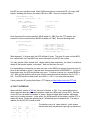
You must set the microcontroller’s SPI control register (SPCR) to enable SPI communication.
This is an eight-bit register that contains the following bits:
SPCR = 0x50:
bit 7
SPIE
0
bit 6
SPE
1
bit 5
DORD
0
bit 4
MSTR
1
bit 3
CPOL
0
bit 2
CPHA
0
bit 1
SPR1
0
bit 0
SPR0
0
The first bit on the left, SPIE, enables the SPI interrupt and is not needed for this application.
The SPE bit enables SPI. DORD determines the data direction: when 0, the most-significant
bit is sent & received first. MSTR determines if the micro acts as a master (1) or slave (0)
device. CPOL and CPHA together determine the transfer mode. Our TFT display works well
with Mode 0, in which both bits are zero. Finally, SPR1 and SPR0 determine the transfer
speed, as a fraction of the microcontroller’s oscillator. When both are 0, the SPI transfer
speed is osc/4, which on my 16 MHz micro is 16/4 = 4 MHz. When both bits are 1, the
transfer speed is osc/256 = 62.5 kHz.
Using an SPCR value of 0x50, SPI is enabled as Master, in Mode 0 at 4 MHz. The code to
open SPI communication can be as simple as the following:
void SPI_Init()
{
SPCR = 0x50;
}
// SPI enabled as Master, Mode0 at 4 MHz
To close SPI, just set the SPE bit to 0. This will stop SPI and return the four dedicated SPI
lines (MOSI, MISO, SCLK, SS) to the general purpose I/O functions:
void SPI_Close()
{
SPCR = 0x00;
}
// clear SPI enable bit
Only one more routine is needed: the SPI transfer routine. SPI is a bidirectional protocol, with
two separate data lines. The data is transmitted over MOSI and received over MISO at the
same time. Even if we only want to send, we are always going to receive. And vice versa. If
you aren’t expecting any received data, just ignore what is returned to you.
The data transfer register is SPDR. Load this register with a value, and the data transfer will
start automatically. A bit in SPSR, the status register, will tell us when the transfer is
complete. As the data bits are serially shifted out of the transfer register, the received bits are
shifted in. When the transfer completes, SPDR will hold the received data:
byte SPI_Xfer(byte data)
{
SPDR = data;
while (!(SPSR & 0x80));
return SPDR;
}
// you can use uint8_t for byte
// initiate transfer
// wait for transfer to complete
3) TESTING THE SPI INTERFACE
The three routines above are all we need for SPI. Let’s make sure they work by doing a serial
loop-back test. In this test, the output data on MOSI is looped-back as the input on MISO.
Whatever value we put into the data register should come right back in.
Without a working display, we need a way to verify the data. You might want to use your fancy
debugger, or send the value to a monitor via UART, but here is something even simpler: flash
the LED on your controller board. Most AVR boards have a connected LED. On many AVR
boards, including the Arduino, the status LED is on PB5. Here is a routine to flash it:
void FlashLED(byte count)
// flash the on-board LED at ~ 2 Hz
{
DDRB |= _BV(DDB5);
for (;count>0;count--)
{
PORTB |= _BV(PORTB5);
_delay_ms(250);
PORTB &= ~_BV(PORTB5);
_delay_ms(250);
}
}
// Set PB5 as output
//
//
//
//
turn LED on
wait
turn LED off
wait
Now, disconnect the microcontroller’s MOSI (digital 11, PB3) from the TFT display, and
connect it to the microcontroller’s MISO line (digital 12, PB4). Run the following code:
void SPI_LoopbackTest()
{
SPI_Init();
char i = SPI_Xfer(5);
SPI_Close();
FlashLED(i+1);
//
//
//
//
//
//
start communication to TFT
MISO to MOSI -> returns 5
MISO to +5V -> returns 255
MISO to Gnd -> returns 0
return portB lines to general use
flash (returned value + 1)
}
What happens? If all goes well, the LED will flash 6 times. The value 5 is sent out the MOSI
line, comes back in on the MISO line, and is returned from the SPI xfer routine.
You may wonder if Xfer worked at all. Maybe nothing was transferred: the value 5 could have
stayed in the transfer register ‘untouched’. How can we know for sure?
For the doubters out there like me, take your wire on the MISO line and put to ground (logic 0).
Now, all bits shifted-in will be 0, and the value returned should be 0x00000000 = 0. If you run
the program now, the LED should flash only once. To further convince you, connect MISO to
+5V. Now, all bits shifted-in will be one, and the value returned will always be 0x11111111 =
255. The LED should not flash at all, since 255+1 = 256 = 0, for byte-sized variables.
I have posted an SPI project that drives a TFT display at http://w8bh.net/avr/AvrTFT.pdf
4) THE I2C INTERFACE
Atmel calls their version of I2C the “two-wire” interface, or TWI. It is a serial-data protocol
which uses two data lines for communication: a data line (SDA) and a clock (SCL). Devices
on the I2C bus can either be masters or slaves. Masters initiate data transfers, and slaves
react only to master requests. In this article, the AVRmega328 is the master, and the RTC is
always the slave. Slaves are specified by a 7-bit address, plus a read/write bit. The device
address for the DS1307 is fixed at 0xd0.
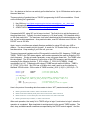
The interface circuit is “open collector”, which means
that the data lines are passively kept high by resistors to
Vcc. Any device on the bus can actively pull a data line low. Up to 128 devices can be put on
the same data bus.
There are plenty of good articles on TWI/I2C programming for AVR microcontrollers. Check
out the following for a good start:
1. Non-GNU.org: http://www.nongnu.org/avr-libc/user-manual/group__twi__demo.html
2. AVR beginners: http://www.avrbeginners.net/architecture/twi/twi.html
3. ATMEL AVR315: http://www.atmel.com/Images/doc2564.pdf
Compared with SPI, using I2C is a bit more involved. The first job is to set the frequency of
the serial data clock. Typically, the clock frequency is 10 (slow mode), 100 (standard mode),
or 400 (fast mode) kHz. The maximum clock rate is determined by the slowest device on the
bus, as well as bus capacitance. As a practical matter, most I2C devices run at 100 kHz. The
DS1307 runs at 100 kHz.
Again, keep in mind there are already libraries available for using I2C with your AVR or
arduino. You do not need to do this yourself. A search for ‘I2C master library’ will turn up a
few alternatives. Keep reading if you’d like roll your own.
There are two special registers on the ATmega which control the SCL frequency: TWSR and
TWBR. TWSR is the TWI status register, and contains prescalar bits used to divide the CPU
clock frequency. We do not need a prescalar, so we can ignore these bits. The TWBR is the
bit-rate register. The SCL frequency is a function of the CPU frequency and this register,
according to the following formula: F_SCL in MHz = F_CPU/(16+2(TWBR)). Kinda
complicated, isn’t it? To determine the value of TWBR we can rewrite it like this: TWBR =
((F_CPU/F_SCL)-16)/2. My CPU has a 16 MHz clock, and I want to run the interface in
standard 100 kHz mode. So the value of TWBR must be ((16/0.1)-16)/2 = (160-16)/2 = 72.
#define F_CPU
#define F_SCL
16000000L
100000L
// CPU clock speed 16 MHz
// I2C clock speed 100 kHz
void I2C_Init()
// at 16 MHz, the SCL frequency will be 16/(16+2(TWBR)), assuming prescalar of 0.
// so for 100KHz SCL, TWBR = ((F_CPU/F_SCL)-16)/2 = ((16/0.1)-16)/2 = 144/2 = 72.
{
TWSR = 0;
// set prescalar to zero
TWBR = ((F_CPU/F_SCL)-16)/2;
// set SCL frequency in TWI bit register
}
Here is the protocol for sending data from master to slave: “MT” (master transmit) mode
Master generates Start Condition, status code 0x08 is returned
Master sends slave address (0xd0), slave device returns ACK, status code 0x18
Master sends one or more data bytes, slave device returns ACK, status code 0x28
Master generates Stop Condition, no status code returned
After each operation, the ‘ready’ bit in TWCR will go to logic 0, and return to logic 1 when the
operation is completed. Byte-sized data is sent/received via the special TWDR register. The
start, stop, and data transfer conditions are specified by the TWCR control register. And the
status codes are put in the TWSR register. Let’s look at the code and compare it to the
protocol. Here is how to generate a start condition:
#define TW_START
#define TW_READY
#define TW_STATUS
0xA4
(TWCR & 0x80)
(TWSR & 0xF8)
byte I2C_Start()
// generate a TW start condition
{
TWCR = TW_START;
while (!TW_READY);
return (TW_STATUS==0x08);
}
// send start condition (TWINT,TWSTA,TWEN)
// ready when TWINT returns to logic 1.
// returns value of status register
// send start condition
// wait
// return 1 if found; 0 otherwise
To generate a start, load TWCR with 0xA4 and wait. That’s all there is to it. Why 0xA4? 0xA4
is binary 10100100. The three ‘1’ values correspond to the TWINT, TWSTA, and TWEN bits
of the control register. These bits enable the TWI interrupt, the start-condition, and the whole
TWI module. You will see many people write it like this: TWCR = (1<<TWINT) | (1<<TWSTA) |
(1<<TWEN). Most think that this ‘self-documenting’ style of coding is preferable, so please
use it if you like. For me, start is simply code 0xA4.
The next thing to do is send the bus address of the slave we are communicating with. For
example, the DS1307 real-time clock has a bus address of 0xd0. Here is our code to do that:
#define DS1307
#define TW_SEND
0xD0
0x84
byte I2C_SendAddr(addr)
// send bus address of slave
{
TWDR = addr;
TWCR = TW_SEND;
while (!TW_READY);
return (TW_STATUS==0x18);
}
// I2C bus address of DS1307 RTC
// send data (TWINT,TWEN)
//
//
//
//
load device's bus address
and send it
wait
return 1 if found; 0 otherwise
Put the address of the slave device into TWDR, put the send command in TWCR, and wait.
The next operation, sending a data byte, looks almost exactly the same. Notice that the
returned status code will be different, however:
byte I2C_Write (byte data)
{
TWDR = data;
TWCR = TW_SEND;
while (!TW_READY);
return (TW_STATUS!=0x28);
}
// sends a data byte to slave
//
//
//
//
load data to be sent
and send it
wait
return 1 if found; 0 otherwise
For the DS1307 we will do this Write operation twice: once to set the address pointer on the
RTC, and again to supply the data for that address.
The last step is the send the Stop condition. Here we just set the command register to 0x94,
the value for TW_STOP. Again, this value sets the TW enable, TW interrupt, and TW stop
bits. Go ahead, use (1<<TWINT) | (1<<TWEN) | (1<<TWSTO) if you prefer. We do not have
to wait or check for status codes, so it is just a one-line command. Instead of writing a routine
I made a macro instead:
#define TW_STOP
#define I2C_Stop()
0x94
TWCR = TW_STOP
// send stop condition (TWINT,TWSTO,TWEN)
// inline macro for stop condition
Just a quick note on the status codes: I’ve written my routines to check the status, but I ignore
the results. In my simple setup this works OK. You may want to check each code and show
error messages when appropriate.
Reading data is little trickier: we have to write to the device first, to set its internal address
pointer, and then read to get the data at that address. Here is the protocol for receiving data
from the slave.
Master generates Start Condition, status code 0x08 is returned
Master sends slave bus address (0xd0), DS1307 returns ACK, status code 0x18
Master sends address pointer, slave device returns ACK, status code 0x28
Master generates another Start Condition = restart, status code 0x10 returned
Master sends slave bus address + read bit (0xd1), slave returns ACK, status code 0x40
Master requests data byte with NACK, slave returns byte, status code 0x58
Master sends Stop condition, no status code returned
The only new code required for reading is the read operation in the next to last step. It looks
very similar to the write operation. NACK is used to a request of a single (or last) byte of data.
#define TW_NACK
#define READ
byte I2C_ReadNACK ()
{
TWCR = TW_NACK;
while (!TW_READY);
return TWDR;
}
0x84
1
// read data with NACK (last byte)
// reads a data byte from slave
// nack = not reading more data
// wait
Putting it all together, here are sample routines for reading and writing registers on the slave
device. You will need to check the datasheet of the slave device you intend to use; each
device may have its own unique protocol for addressing its registers, memory contents, etc.
void I2C_WriteRegister(byte deviceRegister, byte data)
{
I2C_Start():
I2C_SendAddr(DS1307);
// send bus address
I2C_Write(deviceRegister);
// first byte = device register address
I2C_Write(data);
// second byte = data for device register
I2C_Stop();
}
byte I2C_ReadRegister(byte deviceRegister)
{
byte data = 0;
I2C_Start();
I2C_SendAddr(DS1307);
// send device bus address
I2C_Write(deviceRegister);
// set register pointer
I2C_Start();
I2C_SendAddr(DS1307+READ);
data = I2C_ReadNACK();
I2C_Stop();
return data;
// restart as a read operation
// read the register data
// stop
}
I wrote a RTC tutorial using the I2C interface at http://w8bh.net/avr/AvrDS1307.pdf
5) THE UART INTERFACE
Compared to I2C, using the UART is darn-easy. UART stands for Universal Asynchronous
Receive/Transmit. The hardware can also run in synchronous mode, so it is often called a
USART. A good article about the hardware is at avrbeginners.net. And a good programming
reference is Dean Camera’s UART article at fourwalledcubicle.com.
Typical speed
Typical use
SPI
1-20 MHz
High-speed hardware
I2C
100-400 kHz
Multiple devices on a
common bus
UART
9 – 56 kHz
Keyboard, character
LCD/Monitor
As opposed to SPI and I2C, which are often used for binary data exchange between hardware
devices, UART is often used for transmission of (slower) ASCII data. For example, you might
use the UART for keyboard input or monitor/character LCD output. Speedy SPI transfers data
to dedicated hardware devices at MHz speeds, while UART transfers are a thousand times
slower.
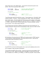
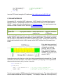
Each data frame consists of
a start bit, a variable number
of data bits, an optional
parity bit, and 1 or 2 stop
bits. The most common
configuration is 1 start bit, 8
data bits, no parity bit, and 1
stop bit (“8N1”).
In asynchronous mode, there is no clock line: data is transmitted on the transmit line (Tx) and
received on the receive line (Rx). The UART is initialized by configuring control registers that
determine the baud rate, parity, number of stop bits:
#define BAUDRATE 9600
void UART_Init()
{
UBRR0 = F_CPU/(BAUDRATE*16L)-1;
UCSR0B = 0x18;
UCSR0C = 0x06;
}
// set speed according to BAUDRATE define
// enable UART: set Rx,Tx enable bits
// set mode: 8 data bits, no parity, 1 stop bit
The first control register, UBRR0, controls the data transmission rate. The value is determined
from the desired baud rate and CPU frequency. For example, a baud rate of 9600 bps on my
16 MHz controller requires a register value of (16000000/9600/16)-1 = 130. Setting bits 4 and
3 in the second control register UCSR0B, enables the special Rx & Tx data lines. The third
control register, UCSR0C, sets the data frame format. For 8N1, the most common data frame
format, the register value should be set to 0x06. Check out the AVRmega328 datasheet for
information on all of the available options.
Once initialized, the controller handles all of the implementation details. Reading & writing
byte-sized data from/to the UART data register, UDR0, looks like this:
#define RX_READY (UCSR0A & 0x80)
#define TX_READY (UCSR0A & 0x20)
void UART_Write(byte data)
{
while (!TX_READY);
UDR0 = data;
}
byte UART_Read()
{
while (!RX_READY);
return UDR0;
}
// check bit7 of UCSRA0
// check bit5 of UCSRA0
// wait until ready to send
// OK, send it now!
// wait until byte rec'd
// OK, return it.
In both routines, the first line waits until the UART is ready to send/receive. The second line
writes/reads the data register. That’s pretty simple, isn’t it?
6) TESTING THE UART INTERFACE
The UART uses two data lines, so try a loopback test like the one for SPI. Tie the Tx
(PD1/TxD) and Rx (PD0/RxD) lines together, and run the following routine:
void UART_LoopbackTest()
{
UART_Write(5);
byte b = UART_Read();
FlashLED(b);
}
// send a '5' out the Tx line
// listen on Rx line
// indicate value returned
If all goes well, the LED should flash 5 times.
7) MAKING LIBRARIES
Each of the interfaces is a great candidate for a library. For example, put the three SPI
routines in a file called spi.c. Then make a header file called spi.h that includes only the
function declarations. Do the same for UART and I2C. Now you can include whichever
interface you need like this:
include “spi.h”
8) DS1307 RTC REVISITED
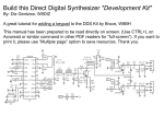
In the DS1307 tutorial I used a character LCD for output.
Let’s use the UART interface to use our computer screen
instead. The AVR TxD and RxD lines require additional
hardware to connect back to your PC. In the ‘old days’,
all PCs had RS232 serial ports, and you would use a
Max232 chip to convert the +/- 12V signals from the
computer to the TTL (+5V) logic levels on the micro. A
quick internet search for “Max232 module” will give you
several options costing around $5. To the left is one
available for around $3 at NewEgg.
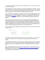
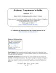
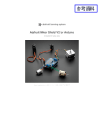
However, most modern PCs have abandoned
RS232 ports and use USB ports instead. To
connect AVR serial lines to USB I use the “FTDI
friend” adapter from Adafruit. It will set you back
about $15. Connect TxD to the adapter input line
(Rx), RxD to the output line (Tx), and GND to
ground.
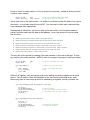
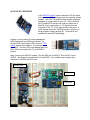
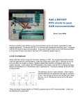
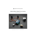
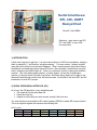
Next, connect your DS1307 module. Run the SDA line to A4/PC4. Run the SCL line to
A5/PC5. And power the module with +5V and GND. Your module must include pullup
resistors on the SDA and SCL lines.
DC Boarduino
DS1307 RTC
FTDI Friend
You should have two lines running from the clock module to the micro, and two lines from the
micro your USB adapter.
Once everything is connected, verify that your computer recognizes the FTDI board. Connect
a USB cable between your computer and the adapter, and then check the computer’s device
manager -> ports. You should see a USB serial port listed, such as ‘COM9’. If not, follow the
device manufacturer’s recommendation for installing the appropriate driver.
Next, you need a console application. Windows used to have a preinstalled application called
‘Hypertext’, but it is no longer available on all computers. I recommend one called ‘PuTTY’,
which available at putty.org and elsewhere. In putty.exe, select connection type: serial and
enter the name of the communication port, such as ‘COM9’, that you got from the device
manager.
If you are doing this for the very first time, you can easily verify that the USB adapter and
console app are configured correctly: temporarily disconnect both data lines between the
micro and the adapter. Now do a loopback test by connecting the adapter’s Tx and Rx lines
together. Anything you type in the console application will be sent out the Tx line, back into
Rx, and be displayed on the console screen. If you have more than one application running
on your computer, make sure the console app is ‘on top’ and has focus.
Once the console app and USB adapter are working, let’s add our microcontroller and extend
the loopback test:
void Typewriter()
{
for(char ch=0; ch!='!';)
{
ch = UART_Read();
UART_Write(ch);
if (ch=='\r')
UART_Write('\n');
}
}
// wait for stop char '!'
//
//
//
//
get byte from keyboard
send it to output
if it is a <return>
add a <newline>
This code will read a byte from the UART and echo it back to the console. There is a check
for the return character, since <return> doesn’t bump the cursor to the next line on my
console.
Now, instead of writing to the LCD via LCD_Char(), we send the data to the computer screen
via UART_Write(). The source code below shows the slightly modified routines. In addition,
we can prompt the user for updated time information, and get the information via keyboard
input.
Many console applications do terminal-emulation, and allow you to control the cursor and
display colors via escape-codes. See http://ascii-table.com/ansi-escape-sequences.php for a
list of these codes. In the source code, ANSI escape sequences are used for clearing the
screen and for setting cursor position.
9) SOURCE CODE
//----------------------------------------------------------------------------// Serial interfaces: useful SPI, I2C, and UART routines
//
// Author
: Bruce E. Hall <[email protected]>
// Website : http://w8bh.net/avr/serial.pdf
// Version : 1.0
// Date
: 12 May 2014
// Target
: ATmega328P microcontroller
// Language : C, using AVR studio 6
// Size
: 1994 bytes
//
// Fuse settings: 8 MHz osc with 65 ms Delay, SPI enable; *NO* clock/8
//
// Demo will get time & date info from from DS1307-RTC module via I2C
// and display time & date on computer console via UART.
//
//
//
--------------------------------------------------------------------------GLOBAL DEFINES
#define
#define
#define
#define
F_CPU
16000000
LED
5
ClearBit(x,y) x &= ~_BV(y)
SetBit(x,y) x |= _BV(y)
//
//
--------------------------------------------------------------------------INCLUDES
#include <avr/io.h>
#include <util/delay.h>
#include <stdlib.h>
//
//
// run CPU at 16 MHz
// Boarduino LED on PB5
// equivalent to cbi(x,y)
// equivalent to sbi(x,y)
// deal with port registers
// used for _delay_ms function
// used for itoa, atoi
--------------------------------------------------------------------------TYPEDEFS
typedef uint8_t byte;
typedef int8_t sbyte;
// I just like byte & sbyte better
//
//
--------------------------------------------------------------------------GLOBAL VARIABLES
//
//
--------------------------------------------------------------------------MISC ROUTINES
void msDelay(int delay)
{
for (int i=0;i<delay;i++)
_delay_ms(1);
}
void FlashLED(byte count)
// flash the on-board LED at ~ 3 Hz
{
SetBit(DDRB,LED);
for (;count;count--)
{
SetBit(PORTB,LED);
msDelay(100);
ClearBit(PORTB,LED);
msDelay(200);
}
}
// put into a routine
// to remove code inlining
// at cost of timing accuracy
// make sure PB5 is an output
//
//
//
//
turn LED on
wait
turn LED off
wait
long IntToBCD (int i)
// converts an integer into its Hex BCD equivalent.
{
Ex: decimal 32 --> 0x32
long ans = 0;
byte digit, shiftvalue = 0;
while (i>0)
{
digit = (i % 10);
ans += (digit << shiftvalue);
i /= 10;
shiftvalue += 4;
}
return ans;
//
//
//
//
get least significant decimal digit
add it in proper position
remove least significant digit
bump up digit position in answer
}
//
//
//
//
//
//
//
//
//
//
//
//
//
//
//
//
//
//
//
//
//
//
//
//
//
//
//
//
//
//
--------------------------------------------------------------------------SPI ROUTINES
How to use the SPI:
1.
2.
3.
4.
5.
6.
7.
The data rate is set in SPI_Init, by setting bits in the SPCR (below).
By default, the rate is FCPU/2 = 8 MHz for a 16 MHz board.
The microcontroller is Master, and the external device is Slave.
Connect the transmit line (MOSI/D11/PB3) to the external device MOSI line.
Connect the receive line (MISO/D12/PB4) to the external device MISO line.
Connect the serial clock (SCK/D13/PB5) to the external device SCK line
Ground the external device select line; usually select is active-low.
Start the SPI with SPI_Init.
Transfer bytes between micro and device with SPI_Xfer
SPI Status Control Register (SPCR) --------SPCR:
SPIE
SPE
DORD
MSTR
CPOL
CPHA
SPRx
-
b7
SPIE
0
b6
SPE
1
b5
DORD
0
b3
CPOL
0
b2
CPHA
0
b1
SPR1
0
b0
SPR0
1
enable SPI interrupt
enable SPI
0=MSB first, 1=LSB first
0=slave, 1=master
0=clock starts low, 1=clock starts high
0=read on rising-edge, 1=read on falling-edge
00=osc/4, 01=osc/16, 10=osc/64, 11=osc/128
SPCR = 0x50:
SPI enabled as Master, mode 0, at 16/4 = 4 MHz
void SPI_Init()
{
SPCR = 0x50;
SetBit(SPSR,SPI2X);
}
void SPI_Close()
{
SPCR = 0x00;
}
byte SPI_Xfer(byte data)
{
SPDR = data;
while (!(SPSR & 0x80));
return SPDR;
}
//
//
//
//
//
//
//
//
b4
MSTR
1 .
// SPI enabled as Master, Mode0 at 4 MHz
// double the SPI rate: 4-->8 MHz
// clear SPI enable bit
// initiate transfer
// wait for transfer to complete
--------------------------------------------------------------------------I2C (TWI) ROUTINES
How to use the I2C:
1.
Set the data transmission speed in the F_SCL define.
Common speeds are 100 kHz (100000L) and 400 kHz (400000L).
The microcontroller is Master, and the external device is Slave.
//
//
//
//
//
//
//
//
//
//
//
2.
3.
4.
5.
6.
#define
#define
#define
#define
#define
#define
#define
#define
#define
#define
Connect the data line (SDA/PC4) to the external device SDA line.
Connect the clock (SCL/PC5) to the external device SCL line
Attach 3.3K pullup resistors from SDA to Vcc and SCL to Vcc.
Start the SPI with I2C_Init.
Reading & Writing data to is often device specific:
use I2C_Send to send a 'raw' byte over the bus
use I2C_Write to send a byte to a specific bus address
use I2C_WriteRegister to send a byte to a specific device register
use I2C_ReadAck to read a byte from slave, with an acknowledgment
use I2C_ReadNACK to read a byte from slave, with no acknowledgment
use I2C_ReadRegister to read a byte from a specific device register
F_SCL
READ
TW_START
TW_STOP
TW_ACK
TW_NACK
TW_SEND
TW_READY
TW_STATUS
I2C_Stop()
100000L
1
0xA4
0x94
0xC4
0x84
0x84
(TWCR & 0x80)
(TWSR & 0xF8)
TWCR = TW_STOP
// I2C clock speed 100 KHz
//
//
//
//
//
//
//
//
send start condition (TWINT,TWSTA,TWEN)
send stop condition (TWINT,TWSTO,TWEN)
return ACK to slave
don't return ACK to slave
send data (TWINT,TWEN)
ready when TWINT returns to logic 1.
returns value of status register
inline macro for stop condition
void I2C_Init()
// at 16 MHz, the SCL frequency will be 16/(16+2(TWBR)), assuming prescalar of 0.
// so for 100KHz SCL, TWBR = ((F_CPU/F_SCL)-16)/2 = ((16/0.1)-16)/2 = 144/2 = 72.
{
TWSR = 0;
// set prescalar to zero
TWBR = ((F_CPU/F_SCL)-16)/2;
// set SCL frequency in TWI bit register
}
byte I2C_Detect(byte addr)
// look for device at specified address; return 1=found, 0=not found
{
TWCR = TW_START;
// send start condition
while (!TW_READY);
// wait
TWDR = addr;
// load device's bus address
TWCR = TW_SEND;
// and send it
while (!TW_READY);
// wait
return (TW_STATUS==0x18);
// return 1 if found; 0 otherwise
}
byte I2C_FindDevice(byte start)
// returns with address of first device found; 0=not found
{
for (byte addr=start;addr<0xFF;addr++) // search all 256 addresses
{
if (I2C_Detect(addr))
// I2C detected?
return addr;
// leave as soon as one is found
}
return 0;
// none detected, so return 0.
}
void I2C_Start(byte slaveAddr)
{
I2C_Detect(slaveAddr);
}
byte I2C_Send(byte data)
{
TWDR = data;
TWCR = TW_SEND;
while (!TW_READY);
return (TW_STATUS!=0x28);
}
// sends a data byte to slave
byte I2C_ReadACK()
{
TWCR = TW_ACK;
while (!TW_READY);
// reads a data byte from slave
// load data to be sent
// and send it
// wait
// ack = will read more data
// wait
return TWDR;
//return (TW_STATUS!=0x28);
}
byte I2C_ReadNACK()
{
TWCR = TW_NACK;
while (!TW_READY);
return TWDR;
//return (TW_STATUS!=0x28);
}
// reads a data byte from slave
// nack = not reading more data
// wait
void I2C_Write(byte busAddr, byte data)
{
I2C_Start(busAddr);
// send bus address
I2C_Send(data);
// then send the data byte
I2C_Stop();
}
void I2C_WriteRegister(byte busAddr, byte deviceRegister, byte data)
{
I2C_Start(busAddr);
// send bus address
I2C_Send(deviceRegister);
// first byte = device register address
I2C_Send(data);
// second byte = data for device register
I2C_Stop();
}
byte I2C_ReadRegister(byte busAddr, byte deviceRegister)
{
byte data = 0;
I2C_Start(busAddr);
// send device address
I2C_Send(deviceRegister);
// set register pointer
I2C_Start(busAddr+READ);
// restart as a read operation
data = I2C_ReadNACK();
// read the register data
I2C_Stop();
// stop
return data;
}
//
//
//
//
//
//
//
//
//
//
//
//
--------------------------------------------------------------------------USART ROUTINES
How to use the USART:
1.
2.
3.
4.
5.
Set the serial transmission speed in the BAUDRATE define. Common baud
rates are: 300, 1200, 2400, 4800, 9600, 14400, 19200, 28800, 57600.
The mode is set at 8 data bits, 1 stop bit, no parity (most common).
Connect the transmit line (Tx/PD1) to the external device Rx line.
Connect the receive line (Rx/PD0) to the external device Tx line.
Start the UART with UART_Init.
Send bytes with UART_Write; Receive bytes with UART_Read.
#define BAUDRATE 9600
#define RX_READY (UCSR0A & 0x80)
#define TX_READY (UCSR0A & 0x20)
void UART_Init()
{
UBRR0 = F_CPU/(BAUDRATE*16L)-1;
UCSR0B = 0x18;
UCSR0C = 0x06;
}
void UART_Close()
{
UCSR0B = 0x00;
}
void UART_Write(byte data)
{
while (!TX_READY);
// check bit7 of UCSRA0
// check bit5 of UCSRA0
// set speed according to BAUDRATE define
// enable UART: set Rx,Tx enable bits
// set mode: 8 data bits, no parity, 1 stop bit
// disable Rx,Tx
// wait until ready to send
UDR0 = data;
// OK, send it now!
}
byte UART_Read()
{
while (!RX_READY);
return UDR0;
}
// wait until byte rec'd
// OK, return it.
byte UART_KeyPressed()
// returns 0x80 if input available; 0 otherwise
{
return RX_READY;
}
void UART_SendString(char *st)
// send a string to the UART
{
for (;*st;st++)
UART_Write(*st);
}
// for each non-nul character
// send it to uart
char * UART_GetString(char *st)
// get a string of characters [80 max!!] from the UART
// string is returned when <enter> key is pressed
{
char c;
byte count=0;
while ((count<80) && ((c = UART_Read()) != '\r'))
{
UART_Write(c);
// echo char back to console
st[count++] = c;
// add char to string
}
st[count]='\0';
// add NULL termination
return st;
}
// --------------------------------------------------------------------------// DS1307 RTC ROUTINES
#define
#define
#define
#define
#define
#define
#define
#define
#define
#define
#define
DS1307 0xD0
SECONDS_REGISTER 0x00
MINUTES_REGISTER 0x01
HOURS_REGISTER 0x02
DAYOFWK_REGISTER 0x03
DAYS_REGISTER 0x04
MONTHS_REGISTER 0x05
YEARS_REGISTER 0x06
CONTROL_REGISTER 0x07
RAM_BEGIN 0x08
RAM_END 0x3F
// I2C bus address of DS1307 RTC
void DS1307_GetTime(byte *hours, byte *minutes, byte *seconds)
// returns hours, minutes, and seconds in BCD format
{
*hours = I2C_ReadRegister(DS1307,HOURS_REGISTER);
*minutes = I2C_ReadRegister(DS1307,MINUTES_REGISTER);
*seconds = I2C_ReadRegister(DS1307,SECONDS_REGISTER);
if (*hours & 0x40) // 12hr mode:
*hours &= 0x1F; // use bottom 5 bits (pm bit = temp & 0x20)
else *hours &= 0x3F; // 24hr mode: use bottom 6 bits
}
void DS1307_GetDate(byte *months, byte *days, byte *years)
// returns months, days, and years in BCD format
{
*months = I2C_ReadRegister(DS1307,MONTHS_REGISTER);
*days = I2C_ReadRegister(DS1307,DAYS_REGISTER);
*years = I2C_ReadRegister(DS1307,YEARS_REGISTER);
}
void DS1307_Now(byte *months, byte *days, byte *years, byte *hours, byte *minutes, byte *seconds)
{
DS1307_GetDate(months, days, years);
DS1307_GetTime(hours, minutes, seconds);
}
void DS1307_SetTimeDate(byte mon, byte day, byte year, byte hour, byte min)
// note: hours are 0-23, years are 2-digit (2014 is 14).
{
byte adj = 0;
if (hour>11)
{
hour -= 12;
adj = 0x40;
// set 12-hr mode
}
I2C_WriteRegister(DS1307,MONTHS_REGISTER, IntToBCD(mon));
I2C_WriteRegister(DS1307,DAYS_REGISTER, IntToBCD(day));
I2C_WriteRegister(DS1307,YEARS_REGISTER, IntToBCD(year));
I2C_WriteRegister(DS1307,HOURS_REGISTER, IntToBCD(hour)+adj);
I2C_WriteRegister(DS1307,MINUTES_REGISTER, IntToBCD(min));
I2C_WriteRegister(DS1307,SECONDS_REGISTER, 0x00);
// seconds at :00
}
// --------------------------------------------------------------------------// APPLICATION ROUTINES
void Generic_PutChar(char ch)
// called when its time to output a character
// output device can be UART, LCD, whatever...
{
UART_Write(ch);
}
void TwoDigits(byte data)
// helper function for WriteDate() & WriteTime()
// input is two digits in BCD format
// output is two ASCII numeric characters
{
byte temp = data>>4;
// get upper digit
Generic_PutChar(temp+'0');
// send it
data &= 0x0F;
// get lower digit
Generic_PutChar(data+'0');
// send it
}
void WriteDate()
// outputs the current date in mm/dd/yy format
{
byte months, days, years;
DS1307_GetDate(&months,&days,&years);
TwoDigits(months);
// mm
Generic_PutChar('/');
TwoDigits(days);
// dd
Generic_PutChar('/');
TwoDigits(years);
// yy
Generic_PutChar(' ');
}
void WriteTime()
// outputs the current time in hh:mm:ss format
{
byte hours, minutes, seconds;
DS1307_GetTime(&hours,&minutes,&seconds);
TwoDigits(hours);
// hh
Generic_PutChar(':');
TwoDigits(minutes);
// mm
Generic_PutChar(':');
TwoDigits(seconds);
// ss
Generic_PutChar(' ');
}
void UART_SendInt(int data)
// sends the integer value to output console
{
char st[8] = "";
// save enough space for result
itoa(data,st,10);
// convert to ascii string, base 10
UART_SendString(st);
// display it on LCD
}
void UART_SendHex(int data)
// sends the hexadecimal value to output console
{
char st[8] = "";
// save enough space for result
itoa(data,st,16);
// convert to ascii string, base 16
UART_SendString(st);
// display it on LCD
}
void ANSI_GotoXY(int x, int y)
// send ANSI escape code to console that move cursor to x,y
{
UART_SendString("\033[");
UART_SendInt(x);
UART_Write(';');
UART_SendInt(y);
UART_Write('H');
}
void ANSI_ClearScreen()
// sends ANSI escape codes to console that clear the screen
// see: http://ascii-table.com/ansi-escape-sequences.php
{
UART_SendString("\033[2J\033[;H");
// clear & goto top-left
}
void UART_LoopbackTest()
{
UART_Write(5);
byte b = UART_Read();
FlashLED(b);
}
// send a '5' out the Tx line
// list on Rx line
// indicate value returned
int PromptInt(char *prompt)
// prompts user for integer input; returns input value
{
char st[80];
// temp buffer for user input
UART_SendString(prompt);
// display the prompt on console
UART_GetString(st);
// get user's input
return atoi(st);
// convert to integer & return it
}
int PromptHex(char *prompt)
// prompts user for hexadecimal input; returns input value
{
char st[80];
// temp buffer for user input
UART_SendString(prompt);
// display the prompt on console
UART_GetString(st);
// get user's input
return strtol(st,NULL,16);
// convert to integer & return it
}
void Console_SetTimeDate()
// interactive way to set DS1307 date & time via TTY console
{
int mon, day, year, hour, min;
mon = PromptInt("\r\nEnter the month (1-12, or 0 to skip): ");
if (!mon) return;
day = PromptInt("\r\nEnter the day (1-31): ");
year = PromptInt("\r\nEnter the 2-digit year: ");
hour = PromptInt("\r\nEnter the hours (0-23): ");
min = PromptInt("\r\nEnter the minutes (0-59): ");
DS1307_SetTimeDate(mon,day,year,hour,min);
}
void Typewriter()
{
UART_SendString("\r\n> Welcome to W8BH. Type '!' to stop.\r\n");
for(char ch=0; ch!='!';)
// wait for stop char '!'
{
ch = UART_Read();
// get byte from keyboard
UART_Write(ch);
// send it to output
if (ch=='\r')
// if it is a <return>
UART_Write('\n');
// add a <newline>
}
UART_SendString("\r\n> Bye!\r\n");
}
//
//
--------------------------------------------------------------------------MAIN PROGRAM
int main()
{
UART_Init();
I2C_Init();
//Typewriter();
ANSI_ClearScreen();
Console_SetTimeDate();
ANSI_ClearScreen();
UART_SendString("Welcome to W8BH.
while(1)
{
ANSI_GotoXY(4,6);
WriteDate();
WriteTime();
msDelay(5000);
}
}
Current Time:");
// forever...
// goto line 4, col 6
// show date/time
// wait 5 seconds