1
Arduino
part A
slides rel. 4.3 – free documentation –
2015
© Renato Conte – Arduino - 1 /82 -
Part A
Contents
What is Arduino?
What is an “embedded system”?
The microcontroller Atmega168 / 328
The Arduino board
The software environment
Applications in C++ and exercises
Part B
AVR architecture Atmega328
Part C
ASM
© Renato Conte – Arduino - 2 /82 -
© Renato Conte – Arduino - 3 /82 -
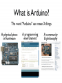
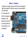
What is Arduino?
Arduino is an open-source electronics prototyping
platform based on flexible, easy-to-use hardware
and software.
It's intended for
artists, designers,
hobbyists, and
anyone interested
in creating interactive objects or environments
© Renato Conte – Arduino - 4 /82 -
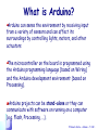
What is Arduino?
Arduino can sense the environment by receiving input
from a variety of sensors and can affect its
surroundings by controlling lights, motors, and other
actuators
The microcontroller on the board is programmed using
the Arduino programming language (based on Wiring)
and the Arduino development environment (based on
Processing).
Arduino projects can be stand-alone or they can
communicate with software on running on a computer
(e.g. Flash, Processing, ...).
© Renato Conte – Arduino - 5 /82 -
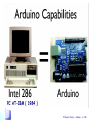
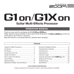
PC AT-IBM ( 1984 )
© Renato Conte – Arduino - 6 /82 -
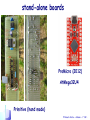
stand-alone boards
ProMicro (2012)
AtMega32U4
Primitive (hand made)
© Renato Conte – Arduino - 7 /82 -
Arduino
© Renato Conte – Arduino - 8 /82 -
What is Arduino?
The boards can be assembled by hand or
purchased preassembled; the software can be
downloaded for free
© Renato Conte – Arduino - 9 /82 -
© Renato Conte – Arduino - 10 /82 -
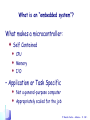
What is an “embedded system”?
What makes a microcontroller:
Self Contained
CPU
Memory
I/O
– Application or Task Specific
Not a general-purpose computer
Appropriately scaled for the job
© Renato Conte – Arduino - 11 /82 -
Designing Embedded Systems
• Microcontrollers
– Don’t have keyboard and monitor jacks
– Must use ports to perform I/O
• Inputs – to sense things
• Outputs – to control things
• Related Component Topics
– Cool Parts
– Common Interfaces
– Part Packages
© Renato Conte – Arduino - 12 /82 -
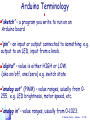
Arduino Terminology
“sketch” – a program you write to run on an
Arduino board
“pin” – an input or output connected to something. e.g.
output to an LED, input from a knob.
“digital” – value is either HIGH or LOW.
(aka on/off, one/zero) e.g. switch state
“analog out” (PWM) – value ranges, usually from 0255. e.g. LED brightness, motor speed, etc.
“analog in” – value ranges, usually from 0-1023.
© Renato Conte – Arduino - 13 /82 -
© Renato Conte – Arduino - 14 /82 -
© Renato Conte – Arduino - 15 /82 -
© Renato Conte – Arduino - 16 /82 -
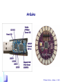
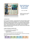
Power Supply
Jumper
only on Arduino Diecimila or older
+
USB 5 Volt
powered from
the
computer's
USB port
external 7-12 Volt
© Renato Conte – Arduino - 17 /82 -
The core: ATmega 168 (328)
8Bit RISC (reduced instruction set computing) Microcontroller
AVR core RISC/modified Harvard
131 instructions, single level pipeline
Up to 16/20 MIPS at 16/20MHz
1 instruction per clock cycle (pipelined)
Memory:
16KB (32KB) Flash memory; 10000 times rewritable
512B (1KB) EEPROM; 100000 times rewritable
1KB (2KB) internal SRAM
© Renato Conte – Arduino - 18 /82 -
© Renato Conte – Arduino - 19 /82 -
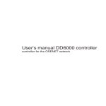
•
•
•
•
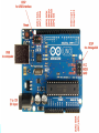
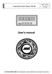
Analog Reference pin (orange)
Digital Ground (light green)
Digital Pins 2-13 (green)
Digital Pins 0-1/Serial In/Out TX/RX (dark green) - These pins
cannot be used for digital i/o
(digitalRead and digitalWrite) if
you are also using serial
communication (e.g. Serial.begin).
•
•
•
•
•
•
Reset Button - S1 (dark blue)
In-circuit Serial Programmer (blue-green)
Analog In Pins 0-5 (light blue)
Power and Ground Pins (power: orange, grounds: light orange)
External Power Supply In (9-12VDC) - X1 (pink)
Toggles External Power and USB Power (place jumper on two pins
closest to desired supply) - SV1 (purple)
• USB (used for uploading sketches to the board and for serial
communication between the board and the computer; can be used to
power the board) (yellow)
© Renato Conte – Arduino - 20 /82 -
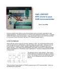
Digital I/O Pins The Arduino I/O board has 14 Digital
pins that can be configured and used individually as Inputs or
Outputs from the program. When a digital pin is configured as
INPUT it can be used to read all kind of sensors that give
values ON and OFF, like push buttons, touch sensors, switches
etc.
When a pin is used as an
OUTPUT it can be used
to turn ON or OFF all
sort of devices, like
light bulbs, motors,
home appliances etc.
© Renato Conte – Arduino - 21 /82 -
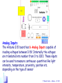
Analog Inputs
The Arduino I/O board has 6 Analog Inputs capable of
.
reading voltages between 0-5V. Internally the voltages
are translated into number from 0 to 1023. These inputs
can be used to measure continuous quantities like light
intensity, temperature, proximity, position etc.
depending on the type of sensor
© Renato Conte – Arduino - 22 /82 -
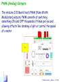
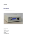
PWM (Analog) Outputs
The Arduino I/O Board has 6 PWM (Pulse Width
Modulation) outputs. PWM consists of switching
something ON and OFF thousands of times per second,
allowing effects like dimming a light or control the speed
of a motor
© Renato Conte – Arduino - 23 /82 -
PWM (Analog) Outputs
Vout = MaxVoltage * T_on_time / T_tot
© Renato Conte – Arduino - 24 /82 -
Serial Ports
The Arduino I/O board also has one hardware
serial port. The Serial serial port is available on
the I/O pins 0 (Rx) and 1 (Tx).
It is used for both
programming the
Arduino I/O board
by software, and to
communicate with
other devices
© Renato Conte – Arduino - 25 /82 -
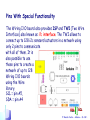
Pins With Special Functionality
The Wiring I/O board also provides ISP and TWI (Two Wire
Interface) also known as i2c interface. The TWI allows to
connect up to 128 i2c sensors/actuators in a network using
only 2 pins to communicate
with all of them. It is
also possible to use
those pins to create a
network of up to 128
Wiring I/O boards
using the Wire
library.
SCL = pin A5,
SDA = pin A4
SDA
SCL
© Renato Conte – Arduino - 26 /82 -
External Interrupts Pins
It is possible to generate and attend external
interrupts on the Wiring I/O board. There are 2
external interrupts, from 0 to 1 so there are 2
pins on the Arduino I/O board capable of
external interrupts,
2 and 3 respectively
In addition to being
regular digital pins,
note that pin 3 is also
used for PWM
© Renato Conte – Arduino - 27 /82 -
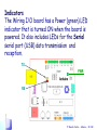
Indicators
The Wiring I/O board has a Power (green) LED
indicator that is turned ON when the board is
powered. It also includes LEDs for the Serial
serial port (USB) data transmission and
reception.
TX
PWR
RX
© Renato Conte – Arduino - 28 /82 -
Arduino environment
Download the Arduino environment
To program the Arduino board you need the
Arduino environment.
(http://www.arduino.cc/files/arduino-1.xx-win.zip)
Locate the USB drivers
You will need to install the drivers (old Arduino
for the FTDI chip on the board ). These can be
found in the drivers/FTDI USB Drivers
directory of the Arduino distribution
© Renato Conte – Arduino - 29 /82 -
Arduino environment
Connect the board
Connect the board to a USB port on your computer.
The power green LED [PWR] should go on .
© Renato Conte – Arduino - 30 /82 -
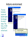
Arduino environment
The new
hardware
wizard will
appear again.
Go through
the same
steps. This
time, a "USB
Serial Port"
will be found.
© Renato Conte – Arduino - 31 /82 -
Arduino environment
Open the
Arduino folder
and double-click
the Arduino
application.
© Renato Conte – Arduino - 32 /82 -
Arduino
environment
13;
© Renato Conte – Arduino - 33 /82 -
compile
upload
to board
Save to
disk
PC
console
status area
© Renato Conte – Arduino - 34 /82 -
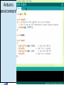
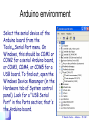
Arduino environment
Select the serial device of the
Arduino board from the
ToolsSerial Port menu. On
Windows, this should be COM1 or
COM2 for a serial Arduino board,
or COM3, COM4, or COM5 for a
USB board. To find out, open the
Windows Device Mananger (in the
Hardware tab of System control
panel). Look for a "USB Serial
Port" in the Ports section; that's
the Arduino board.
© Renato Conte – Arduino - 35 /82 -
Arduino environment
You'll need to specify
your microcontroller.
Look at the main chip on
your Arduino board. It
should say either
ATmega328 or other.
If the latter, you'll
need to select
ATmega328 from the
Tools > Microcontroller
menu.
© Renato Conte – Arduino - 36 /82 -
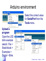
Arduino environment
Select the correct value
for SerialPort from the
Tools menu.
Upload a
program
Open the LED
blink example
sketch: File >
Sketchbook >
Examples >
Digital > Blink.
© Renato Conte – Arduino - 37 /82 -
Arduino
environment
The code for
the LED blink
example
© Renato Conte – Arduino - 38 /82 -
Arduino environment
© Renato Conte – Arduino - 39 /82 -
Arduino environment
Formal activity diagram
Power ON
Reset
[ wait time < 5 sec ]
[ new sketch from PC ]
Interruptible activity region
Execute
existing
sketch
Special Interrupt
request: reset hardware
upload
new
sketch
© Renato Conte – Arduino - 40 /82 -
LAB: Digital In Out
In this lab, you'll connect a digital input
circuit and a digital output circuit to a microcontroller. Though this is written for
the Arduino microcontroller module, the
principles apply to any microcontroller.
© Renato Conte – Arduino - 41 /82 -
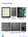
for this lab you'll need:
Solderless breadboard
LEDs
22-AWG
hookup wire
Arduino module
220-ohm and 10Kohm resistors
switch
© Renato Conte – Arduino - 42 /82 -
© Renato Conte – Arduino - 43 /82 -
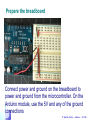
Prepare the breadboard
Connect power and ground on the breadboard to
power and ground from the microcontroller. On the
Arduino module, use the 5V and any of the ground
connections
© Renato Conte – Arduino - 44 /82 -
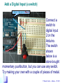
Add a Digital Input (a switch)
Error : No pin 4. Pin 2
Connect a
switch to
digital input
2 on the
Arduino.
The switch
shown
below is a
store-bought
momentary pushbutton, but you can use any switch.
Try making your own with a couple of pieces of metal.
© Renato Conte – Arduino - 45 /82 -
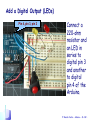
Add a Digital Output (LEDs)
. Pin 4, pin 3, pin 2
Connect a
220-ohm
resistor and
an LED in
series to
digital pin 3
and another
to digital
pin 4 of the
Arduino.
© Renato Conte – Arduino - 46 /82 -
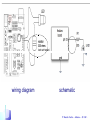
Schematic
Prepare a program
that reads the
digital input on pin 2.
Then it turns on only
the LED on pin 3 if
the input is high (i.e.
the switch is on), or
turns on only the
LED on pin 4 is the
input is low (the
switch is off):
© Renato Conte – Arduino - 47 /82 -
// declare variables:
int switchPin = 2;
//(in photo pin 4) // digital input pin for a switch
int yellowLedPin = 3; //(in photo pin 5) // digital output pin for a yellow LED
int redLedPin = 4; //(in photo pin 6) // digital output pin for a red LED
boolean switchClose = false;
// the state of the switch
void setup()
{ pinMode(switchPin, INPUT);
// set the switch pin to be an input
pinMode(yellowLedPin, OUTPUT); // set the yellow LED pin to be an output
pinMode(redLedPin, OUTPUT);
// set the red LED pin to be an output
}//setup
void loop()
{
switchClose = digitalRead(switchPin); // read the switch input:
if (switchClose )
// if the switch is closed:
{
digitalWrite(yellowLedPin, HIGH); // turn on the yellow LED
digitalWrite(redLedPin, LOW);
// turn off the red LED
}
else
// if the switch is open:
{ digitalWrite(yellowLedPin, LOW); // turn off the yellow LED
digitalWrite(redLedPin, HIGH);
// turn on the red LED
}
} //loop
© Renato Conte – Arduino - 48 /82 -
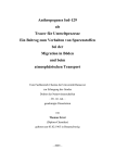
wiring diagram
schematic
© Renato Conte – Arduino - 49 /82 -
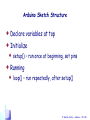
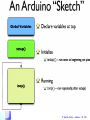
Arduino Sketch Structure
Declare variables at top
Initialize
setup() – run once at beginning, set pins
Running
loop() – run repeatedly, after setup()
© Renato Conte – Arduino - 50 /82 -
© Renato Conte – Arduino - 51 /82 -
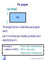
The program
void setup()
{
code
}
The setup() function is called when your program
starts.
Use it to initialize your variables, pin modes, start
using libraries, etc.
void setup(){
//Inizio della configurazione
pinMode(13,OUTPUT); //PIN 13 come output
}
//Termine della configurazione
© Renato Conte – Arduino - 52 /82 -
The program
void loop()
{
}
The loop() function loops consecutively,
allowing your program to change and
respond. Use it to actively control the
Arduino board.
© Renato Conte – Arduino - 53 /82 -
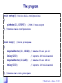
The program
void setup()//Inizio della configurazione
{
pinMode(13,OUTPUT); //PIN 13 come output
} //Termine della configurazione
void loop() //Ciclo principale
{
digitalWrite(13, HIGH);//
Delay(200);
//
digitalWrite(13,LOW); //
delay(100);
//
}
Emette 5V sul pin 13
Aspetta 200 millisecondi
Emette 0V sul PIN 13
Aspetta 100 millisecondi
//Termine del ciclo principale
© Renato Conte – Arduino - 54 /82 -
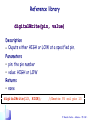
Reference library
digitalWrite(pin, value)
Description
• Ouputs either HIGH or LOW at a specified pin.
Parameters
• pin: the pin number
• value: HIGH or LOW
Returns
• none
digitalWrite(13, HIGH);
//Emette 5V sul pin 13
© Renato Conte – Arduino - 55 /82 -
Defining Pin Levels, HIGH and LOW
When reading or writing to a digital pin there are only two
possible values a pin can take/be-set-to: HIGH and LOW.
• HIGH represents the programming equivalent to 5
volts. When reading the value at a digital pin if there
is 3 volts or more at the input pin, the microprocessor
will understand it as HIGH. This constant is also
represented by the integer number 1, and also the
truth level TRUE.
• LOW is representing the programming equivalent to 0
volts. When reading the value at a digital pin, if we get
2 volts or less, the microprocessor will understand it
as LOW. This constant if also represented by the
integer number 0, and also the truth level FALSE.
© Renato Conte – Arduino - 56 /82 -
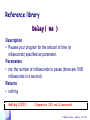
Reference library
Delay( ms )
Description
• Pauses your program for the amount of time (in
miliseconds) specified as parameter.
Parameters
• ms: the number of milliseconds to pause (there are 1000
milliseconds in a second)
Returns
• nothing
delay(200);
//Aspetta 200 millisecondi
© Renato Conte – Arduino - 57 /82 -
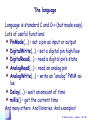
The language
Language is standard C and C++ (but made easy)
Lots of useful functions:
PinMode(...) – set a pin as input or output
DigitalWrite(...) – set a digital pin high/low
DigitalRead(...) – read a digital pin’s state
AnalogRead(...) – read an analog pin
AnalogWrite(...) – write an “analog” PWM value
Delay(...) – wait an amount of time
millis() – get the current time
And many others. And libraries. And examples!
© Renato Conte – Arduino - 58 /82 -
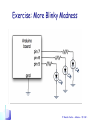
Exercise: More Blinky Madness
© Renato Conte – Arduino - 59 /82 -
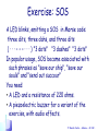
Exercise: SOS
A LED blinks, emitting a SOS in Morse code:
three dits, three dahs, and three dits
( · · · – – – · · · ) "3 dots" "3 dashes" "3 dots"
In popular usage, SOS became associated with
such phrases as "save our ship", "save our
souls" and "send out succour"
You need:
• A LED and a resistance of 220 ohms.
• A piezoelectric buzzer for a variant of the
exercise, with audio effects.
© Renato Conte – Arduino - 60 /82 -
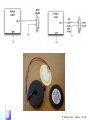
A piezoelectric sounder (buzzer)
A buzzer or beeper is a
signaling device, tipically a
ceramic-based piezoelectric
sounder like a Sonalert which
makes a high-pitched tone.
Usually these were hooked up
to "driver" circuits which
varied the pitch of the sound
or pulsed the sound on and
off.
© Renato Conte – Arduino - 61 /82 -
Piezoelectrics
• Some crystals, when
squeezed, make a spark
• Piezo buzzers use this to
make sound (flex something
back and forth, it moves air)
• Two wires, red & black
• Apply an oscillating voltage to
make a noise
• The buzzer case supports the
piezo element and has
resonant cavity for sound
© Renato Conte – Arduino - 62 /82 -
© Renato Conte – Arduino - 63 /82 -
const int unitLength = 200; // 200 msec: slow operator
const int dotLength = unitLength;
//
const int dashLength = 3* unitLength ; //
const int partSpace= unitLength;
//
const int lettersSpace= 3 * unitLength;
//
const int wordSpace= 7 * unitLength;
//
const int ledPin = 13;
const int buzzerPin = 10;
void setup ( )
{
pinMode( ledPin ,OUTPUT );
//
pinMode( buzzerPin ,OUTPUT ); //
}
© Renato Conte – Arduino - 64 /82 -
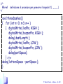
//*
@brief definizione di procedura per generare il segnale S ( . . . )
*/
void threeDots( )
{ for(int n=0; n <3; n++)
{ digitalWrite(ledPin, HIGH);
digitalWrite(buzzerPin, HIGH);
delay( dotLength );
digitalWrite(ledPin,LOW);
digitalWrite(buzzerPin,LOW);
delay( partSpace );
}
delay( lettersSpace – partSpace );
}
© Renato Conte – Arduino - 65 /82 -
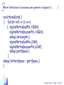
//*
@brief
*/
definizione di procedura per generare il segnale O ( _ _ _ )
void threeDashes( )
{ for ( int n= 0; n<3; n++ )
{ digitalWrite( ledPin, HIGH );
digitalWrite( buzzerPin, HIGH );
delay( dashLength );
digitalWrite( ledPin, LOW );
digitalWrite( buzzerPin, LOW );
delay(partSpace);
} //for
delay( lettersSpace – partSpace );
}
© Renato Conte – Arduino - 66 /82 -
void loop( )
{
threeDots( ); // S signal
threeDashes( ); // O signal
threeDots( );
}
// S signal
delay( wordSpace );
© Renato Conte – Arduino - 67 /82 -
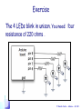
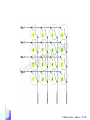
Exercise
The 4 LEDs blink in unison. You need: four
resistance of 220 ohms .
© Renato Conte – Arduino - 68 /82 -
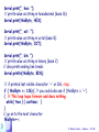
// declare variables:
int catenaLed[ ] = { 6, 7, 8, 9 };
int tempo = 500;
// definition of the Led pins array
void setup()
{ for (int i=0; i<4; i++)
// all the pins as OUTPUT
{ pinMode( catenaLed[ i ],OUTPUT); }
}
void flash( )
{
for (int i=0; i<4; i++)
digitalWrite(catenaLed[ i ], HIGH ); // turn on the LED i
delay(tempo);
for (int i=0; i<4; i++)
digitalWrite( catenaLed[ i ], LOW );
}
// turn off the LED i
delay(tempo);
void loop( ) { flash( ); }
© Renato Conte – Arduino - 69 /82 -
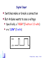
Digital Input
Most inputs you’ll use are variations on switches
Switches make or break a connection
Single pole = only one circuit is being controlled
• Double pole = two
circuits are being
controlled at once
• Single throw = only one
path for circuit
• Double throw = two
potential paths for circuit
© Renato Conte – Arduino - 70 /82 -
Many Kinds of Switches
magnetic hexidecimal
tilt
lever
© Renato Conte – Arduino - 71 /82 -
Tiny Switches
© Renato Conte – Arduino - 72 /82 -
Digital Input
Switches make or break a connection
But Arduino wants to see a voltage
Specifically, a “HIGH” (5 volts or 3.3 volts)
or a “LOW” (0 volts)
© Renato Conte – Arduino - 73 /82 -
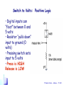
Switch to Volts: Positive Logic
• Digital inputs can
“float” between 0 and
5 volts
• Resistor “pulls down”
input to ground (0
volts)
• Pressing switch sets
input to 5 volts
• Press is HIGH
Release is LOW
© Renato Conte – Arduino - 74 /82 -
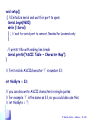
Example from Arduino IDE: File > Examples>Communications>ASCII table
/*
ASCII table
Prints out byte values in all possible formats:
* as raw binary values
* as ASCII-encoded decimal, hex, octal, and binary values
For more on ASCII, see http://www.asciitable.com and
http://en.wikipedia.org/wiki/ASCII
The circuit: No external hardware needed.
created 2006
by Nicholas Zambetti
modified 9 Apr 2012
by Tom Igoe
This example code is in the public domain.
*/
<http://www.zambetti.com>
© Renato Conte – Arduino - 75 /82 -
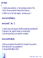
void setup()
{ //Initialize serial and wait for port to open:
Serial.begin(9600);
while (! Serial)
{ ; // wait for serial port to connect. Needed for Leonardo only
}
}
// prints title with ending line break
Serial.println("ASCII Table ~ Character Map");
// first visible ASCIIcharacter '!' is number 33:
int thisByte = 33;
// you can also write ASCII characters in single quotes.
// for example. '!' is the same as 33, so you could also use this:
// int thisByte = '!';
© Renato Conte – Arduino - 76 /82 -
void loop()
{
// prints value unaltered, i.e. the raw binary version of the
// byte. The serial monitor interprets all bytes as
// ASCII, so 33, the first number, will show up as '!'
Serial.write(thisByte);
Serial.print(", dec: ");
// prints value as string as an ASCII-encoded decimal (base 10).
// Decimal is the default format for Serial.print()
// and Serial.println(), so no modifier is needed:
Serial.print(thisByte);
// But you can declare the modifier for decimal if you want to.
//this also works if you uncomment it:
// Serial.print(thisByte, DEC);
© Renato Conte – Arduino - 77 /82 -
Serial.print(", hex: ");
// prints value as string in hexadecimal (base 16):
Serial.print(thisByte, HEX);
Serial.print(", oct: ");
// prints value as string in octal (base 8);
Serial.print(thisByte, OCT);
Serial.print(", bin: ");
// prints value as string in binary (base 2)
// also prints ending line break:
Serial.println(thisByte, BIN);
}
// if printed last visible character '~' or 126, stop:
if ( thisByte == 126) { // you could also use if (thisByte == '~')
{ // This loop loops forever and does nothing
while( true ) { continue; }
}
// go on to the next character
thisByte++;
© Renato Conte – Arduino - 78 /82 -
© Renato Conte – Arduino - 79 /82 -
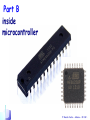
Part B
inside
microcontroller
© Renato Conte – Arduino - 80 /82 -
… continua
nelle prossime serie di slide ...
© Renato Conte – Arduino - 81 /82 -
Part A
General
http://www.arduino.cc
Part B
Hardware (microcontroller)
http://www.atmel.com/devices/ATMEGA328.aspx?tab=documents
• ATMEL DATASHEET: ATmega48A/PA/88A/PA/168A/PA/328/P
http://en.wikipedia.org/wiki/Atmel_AVR
http://courses.cs.washington.edu/courses/csep567/10wi/lectures/
Part C
ASSEMBLY
http://www.avr-asm-tutorial.net/avr_en/AVR_TUT.html
http://www.avrbeginners.net/
http://www.cs.nmsu.edu/~jcook/arduino/index.php?n=Notes.AssemblyMods
http://www.nongnu.org/avr-libc/user-manual/inline_asm.html
© Renato Conte – Arduino - 82 /82 -