1
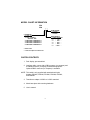
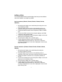
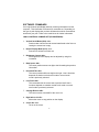
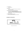
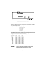
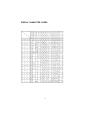
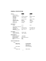
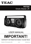
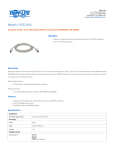
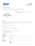
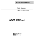
Models: PD3000/PD6000 Series
Customer Displays
2 by 20 character display
USER MANUAL
NOTICE
The manufacturer of the POS pole display makes no representations or
warranties, either expressed or implied, by or with respect to anything in
this manual, and shall not be liable for any implied warranties of fitness for
a particular purpose or for any indirect, special or consequential damages.
Information in this document is subject to change without notice and does
not represent a commitment on the part of the manufacturer.
FCC NOTICE
This equipment generates, uses, and can radiate radio frequency energy
and if not installed and used in accordance with this manual, may cause
interference to radio communications. It has been tested and found to
comply with the limits for a Class A digital device pursuant to Subpart J of
Part 15 of FCC Rules, which are designed to provide reasonable protection
against interference when operated in a commercial environment. Operation
of this equipment in a residential area is likely to cause interference in
which case the user at his own expense will be required to take whatever
measures may be required to correct the interference.
LOGIC CONTROLS, INC.
355 Denton Ave
New Hyde Park, NY 11040
TEL: (516) 248-0400
FAX: (516) 248-0443
Email: [email protected]
http://www.logiccontrols.com
i
TABLE OF CONTENTS
FEATURES ............................................................................... 1
MODEL INFORMATION ........................................................... 2
CARTON CONTENTS .............................................................. 2
INSTALLATION ......................................................................... 3
FUNCTIONAL TEST ................................................................ 4
INTERFACE CONNECTION .................................................... 4
SOFTWARE COMMANDS ....................................................... 6
HARDWARE CONFIGURATION .............................................. 7
DISPLAY CHARACTER CODES .............................................. 9
GENERAL SPECIFICATIONS .................................................. 10
ii
FEATURES and MODELS
The PD3000/PD6000 family of pole displays offers a wide range of high
quality features and models to choice from. Listed below are the features
incorporated into each pole display. Not all features are available in all
models. The model charts will assist you in selecting the model best suited
to your needs.
The PD3000 family has the industry standard 5mm high vacuum fluorescent
5x7 pixel display. The PD6000 family has a pixel height of 11.25mm; one
of the largest vacuum fluorescent display on the market today.
Features - All Models
• Bright green fluorescent display
• Supports high speed serial protocol:
up to 19,200 baud rate, 1 stop bit
• Automatic message scrolling
• Two line display with 20 characters per line
• Matched optical lens for better viewing contrast
• Ergonomic design
• Direct RS232C or parallel interface
• Long life and trouble free operation
• Five adjustable viewing angles
• Simple installation
• Available in different heights
• Available with 120V or 220V Power Adapters
Features - Model dependent
• Emulation of other popular command sets
• Parallel pass-thru
• True RS232C pass-thru
• Real time clock
• One time message scrolling
• Ability to disable attention code
• Ability to change attention code
1
MODEL CHART INFORMATION
PD3
TD3 _ _ _
PD6
POWER ADAPTER
0 = 120VAC *
1 = 220VAC
COMMAND SET
0 = LOGIC CONTROLS *
1 = LOGIC CONTROLS
WITH PASS - THRU
2 = EMULATION COMMAND SET 1 **
3 = EMULATION COMMAND SET 2 **
4 = EMULATION COMMAND SET 3 **
5 = EMULATION COMMAND SET 4 **
SERIAL INTERFACE
0 = SERIAL 9600 BAUD *
1=
"
600 "
2=
"
1200 "
3=
"
2400 "
4=
"
4800 "
5=
" 19200 "
* Default values
** Call for description of Command Set
CARTON CONTENTS
1. Pole display, pre-assembled.
2. Interface cable, comes with a DB9 connector (to computer) and
a DIN6M connector (to display) as standard equipment.
Optional DB25 connector (to computer) is available.
NOTE: This cable is only supplied with standard serial pole
displays PD3000, PD3300, PD3500, PD6000, PD6300,
and PD6500.
3. Transformer adapter 120VAC to 6.0VAC standard.
4. Metal base plate with mounting hardware.
5. User’s manual.
2
INSTALLATION
Your PD3000/PD6000 family of pole displays has been pre-assembled to
make the installation as simple as possible.
Serial Installation (PD3000, PD3300, PD3500, PD6000, PD6300,
PD65000)
1. Mount the pole display to the metal base plate using the mount
ing hardware provided.
2. The pole display can be used in a free-standing mode or at
tached to the counter using the remaining mounting hardware.
3. Connect the DB9 connector to the computer’s COM1 or COM2
port.
4. Connect the DIN6 connector from the pole display to the DIN6
connector of the interface cable.
5. Connect the female phone jack of the power adapter to the male
phone jack of the interface cable.
6. Plug the power adapter into a 120VAC outlet.
7. A green start up message (LOGIC CONTROLS POS
COMPONENTS) will be present for a short time. When this
message disappears the cursor will be displayed in the left-most
digit of the top row.
Parallel Installation (PD3090, PD3390, PD3500, PD6090, PD6390,
PD6590)
1. Mount the pole display to the metal base plate using the
mounting hardware provided.
2. The pole display can be used in a free-standing mode or
attached to the counter using the remaining mounting hardware.
3. Connect the DB25 connector to the computer’s parallel port
(LPT1).
4. Connect the female phone jack of the power adapter to the male
phone jack of the interface cable.
5. Plug the power adapter into a 120VAC outlet.
6. A green start up message (LOGIC CONTROLS POS
COMPONENTS) will be present for a short time. When this
message disappears the cursor will be displayed in the left-most
digit of the top row.
3
FUNCTIONAL TEST
The following test sequence will verify that your pole display is working
properly. Before you start this procedure, you must install the pole
display correctly as outlined under the Installation section.
NOTE: The actual key entries are enclosed within quotation marks
( “ ” ). Do not type the quotation marks as part of your entries.
Serial Pole Displays
This test procedure assumes the pole display is connected to COM1 of the
computer. If COM2 is being used, simple insert COM2 where COM1 is
called out.
1. Type “MODE COM1 96,N,8,1” and press the ENTER key.
2. Type “TYPE CON>COM1” and press the ENTER key.
For PD3000, 3300, 3500, 6000, 6300, 6500 displays
3. Type “ABCDEFGHIJKLMNOPQRS” and press the ENTER key.
The display will show “ABCDEFGHIJKLMNOPQRS” on the first
line.
For PD3090, 3390, 3590, 6090, 6390, 6590 dispalys
1. Type “ECHO ABCDEFGHIJKLMNOPQRS>LPT1” and press the
ENTER key. The display will show “ABCDEFGHIJKLMNOPQRS”
on the first line.
INTERFACE CONNECTION
SERIAL INTERFACE, PD3000/PD6000
All serial pole displays (standard and pass-thru) are factory configured
for serial RS232C interface with the following protocol:
9600 Baud Rate
No Parity
8 Data Bits
1 Stop Bit
No Handshake
4
The pole display also accepts TTL compatible ( 0 and 5-volt levels)
serial ASCII data. If the TTL driver is an open collector device, a pullup resistor must be included in the driver.
Connector configuration
The pin out configuration for the standard serial pole display is a DB9F
connector. It plugs directly into the serial port of the computer.
DB9F
PARALLEL INTERFACE PD3090/PD6090
All standard parallel pole displays will have a DB25 male connector. It is connected to the printer port of the computer.
DB25M
5
SOFTWARE COMMANDS
Your Logic Controls pole display works by receiving information from the
computer. This information is known as a command set. Depending on
the type of pole display that you have will determine which command set
works with your pole. Refer to the model chart for further information.
LOGIC CONTROLS COMAND SET (PD3000/PD6000):
1. Vertical Scroll Mode (DC2) <12>:
Data is written into the second row and transferred to the first row
leaving the second row empty.
2. Normal Display Mode (DC1) <11>:
Data can be written into either row.
3. Brightness Control <04>:
The brightness of the display can be adjusted by using this
command.
4. Back Space <08>:
The cursor position moves one digit to the left erasing the previous
information.
5. Horizontal Tab <09>:
The cursor position shifts one digit to the right. How it functions
depends on whether vertical scroll mode or normal scroll
mode is previously selected.
6. Line Feed <0A>:
This command tells the cursor how to position itself. How it
functions depends on whether vertical scroll mode or normal
scroll mode is previously selected.
7. Carriage Return <0D>:
The cursor moves to the MSD of the row it is in.
8. Digit Select <10><P>:
Moves the cursor to any position on the display
9. Cursor On <13>:
Turns on the cursor.
6
10. Cursor Off <14>:
Turns off the cursor.
11. Reset <1F>:
All characters are erased and all settings are returned to the
power-on eset conditions.
12. Down Load Font <03><X> <F> <F> <F> <F> <F>:
Allows a programmer to assign a keyboard key (ASCII code 20 to
7F) a different style font. The “X” represents the ASCII code for the
selected key. The “F’s” represent the 5 segments which will make
up the special font.
13. Alphanumeric Message Scroll <05>:
Scrolls a continuous message of up to 45 characters.
HARDWARE CONFIGURATION
J
P
8
J
P
6
J
P
7
U2
U1
FD1
LOGIC CONTROLS, INC.
PD3000 POLE DISPLAY MODULE
7
PD3000 POLE DISPLAY MODULE
PD6000 POLE DISPLAY MODULE LAYOUT
Serial pole displays were factory configured for serial RS232C interface
using the following protocol:
· 9600 Baud Rate
· 8 Data Bits
· 1 Stop Bit
· No Parity
Other optional baud rates are available. The jumper locations and pinouts
are shown for reference only. The manufacturer strongly recommends that
changes to the protocol be made at the factory.
Baud Rate
19200
9600
4800
2400
1200
600
300
150
WARNING:
JP6
Open
Open
Open
Open
Close
Close
Close
Close
JP7
Open
Open
Close
Close
Open
Open
Close
Close
JP8
Open
Close
Open
Close
Open
Close
Open
Close
If the user opens the pole display housing to make
changes, all product warranty will be voided.
8
DISPLAY CHARACTER CODES
9
GENERAL SPECIFICATIONS
PD3000
OPTICAL:
Number of rows
Number of digits/row
Dot matrix
Digit height
(11.25mm)
Digit width
Character config.
Brightness (typical)
Display color
MTBF (hours)
MECHANICAL:
Weight
PD6000
2
20
5 x 7 plus underline
0.20in. (5.0mm)
2
20
5X7 plus comma
0.44in.
0.14in. (3.5mm)
ASCII
690 cd/m2
Green-Blue
300,000
0.28in. (7.2mm)
ASCII
700 cd/m2
Green-Blue
300,000
2.4 lb.
2.8 lb.
Dimensions (in inches) (w x h x d)
Display head
7.9 x 3.4 x 1.75
Rectangular base
2.12 x 2.0 x 2.25
Base plate
4.0 x 0.09 x 8.0
Overall height (typical)
25
ELECTRICAL:
Adapter input power
Adapter output power
120VAC, 60HZ
6VAC, 1000ma
ENVIRONMENTAL:
Operating temperature
Storage temperature
Relative Humidity
Vibration (10 to 55 Hz.)
Shock
-10 to +65oC
-40 to +85oC
80%, non-condensing
4G’s
40G’s
11.0 x 3.25 x 1.75
2.12 x 2.0 x 2.25
4.0 x 0.09 x 8.0
25
CABLES & CONNECTORS:
Serial
Display cable
Interface cable
6-pin DIN (male)
6-pin Din (female)
DB9 (female)
Phone jack (male)
Phone jack (female)
Power adapter
Parallel
Display cable
DB25 (female)
10