1
On
Real-Time Systems
and
Processor Architecture
Roger Johansson
Department of Computer Engineering
Chalmers University of Technology
S{412 96 Goteborg
Sweden.
E-mail: [email protected]
June 22, 1993
Abstract
This report discusses the impact of hard real-time systems requirements on microprocessor performance. Certain dependability aspects are alse considered although
not covered in detail. Therefore we discuss hard real-time systems and microprocessors from an architectural point of view as well as system hardware design. The
architectural considerations assume an event triggered hard real-time system with kernel software. The hardware considerations treat a space qualied computer system
compared to a general purpose application.
Hard real-time systems are intended for use in environments where dependability is
a primary design goal. For the majority of common microprocessors, high performance
has been the primary design goal. However, a primary design goal such as high performance introduces conicts with a design goal such as dependability. It is also clear
that a hard real-time system implementation that utilizes a high performance RISC
CPU does not necessarily benet from the high execution rate that the microprocessor
oers.
Keywords: Hard real-time systems, dependability, microprocessor architecture
1
1 Introduction
An important eld of computer exploitation is real-time systems. A real-time system can
be understood as an information processing system which has to respond to externally
generated input stimuli within a nite and specied period [You82]. The functionality of
a real-time system may be divided into three major parts:
1. Get information (INPUT) as soon as it is available
2. Process information
3. Present result (OUTPUT) within the specied period
The time requirements laid upon real-time systems impose a characteristic and an important constraint; a correct result must be presented within a limited time. This time may
very well be a variable and thus dynamically impact on system behaviour. For example
consider the situation at a cross-road guarded by trac lights where the signals should
be optimized for a maximum throughput of vehicles. Another type of time requirement
is introduced in systems where the functionality depends on the system's ability to meet
these requirements. For example consider a system that controls fuel ignition during a
rocket launch. Time requirements that must be met to insure proper system functionality
are called hard time requirements. A real-time system that has to meet hard time requirements is called a hard real-time system. Hard real-time systems are traditionally divided
in two major groups: event triggered systems and time triggered systems. This report is
based on an earlier study in which seven microprocessors ability to perform in an event
triggered real-time system were elaborated and reported [Joh92].
1.1 Event triggered systems
In an event triggered system the software consists of a real-time kernel and the application
programs. The kernel is responsible for process synchronisation and communication as well
a scheduling of processes (application programs) in the system. Furthermore, the kernel
often handles input/output from/to peripheral devices by means of hardware interrupt
facilities. This provides for rapid respons to external stimuli (events) by the use of special
interrupt handling. By the use of an appropriate scheduling algoritm the kernel dispatches
the CPU to the process that most urgently needs to execute.
1.2 Time triggered systems
Similar to an event triggered system, a time triggered system should respond to external
stimuli. In a time triggered system however, the event is not sampled momentary with the
2
real-time event. Rather, the time triggered system checks for real-time events at regular
predetermined intervals. During each interval an input device that reects the event, is
read. Note the distinction between a real-time event and its projection, i.e the time it
becomes known to the system. Obviously these intervals must be constructed to guarantee
that all hard real-time requirement should be met. Consequently the event signal has been
moved from a hardware interrupt mechanism to a software polling mechanism. By removing hardware interrupts and software interrupt handling, time triggered systems provide
us with a fully time-deterministic behaviour, we might exploit the systems functionality
and performance at compile time.
1.3 Dependability
Hard real-time systems are characterized by the fact that severe consequenses will result
if logical or timing correctness properties are not satised. They span many application
areas; avionics, undersea exploration, process control, robot systems, automotives just
to mention a few. While logical and timing correctness should be explored, or proven
if possible, during the design, implementation and test phases, actions must be taken
to handle run-time failures that may arise from transient or permanent hardware errors.
This is accomplished through fault-tolerant hardware designs. Generally, we require a hard
real-time system to be dependable in the sense that catastrophies should be avoided, thus
keeping the system in a safe state. The dependability requirements may be expressed as
[Tor92]:
degree of fault tolerance given as behavioural consequenses of faults, e.g. (fully)
operational after one fault (FO), reduced operation after one fault (FR), safe operation after one fault (FS). For example, the dependability requirement FO/FS
states that a system should be fully operational after one permanent hardware fault,
regardless of which or where, and the system should remain in a safe state even if a
second fault occurs.
tolerable probability of failure that might cause the corresponding safety critical
hazard. For example; a system which at a fault might cause safety critical hazard
should, at the most, in one per million implemented systems cause one hazard per
year.
Obviously, a dependable computer demands its own design philosophy where redundant
parts, high quality components, and careful manufacturing is of major importance.
1.4 Scope
This report discusses the impact of hard real-time requirements on microprocessor performance. Certain dependability aspects are also considered, although not covered in detail.
3
1.5 Objectives
The primary objective with this report is to elaborate the microprocessor's role in a hard
real-time system. Therefore, we discuss hard real-time systems and microprocessors from
an architectural point of view as well as system hardware design.
The architectural considerations assume an event triggered hard real-time system with
kernel software. Seven dierent processors were selected for architectural considerations,
namely;
Motorola MC88100 [Mot90]
Intel Iapx80960 [Int88]
MIPS R2000 (R3000) [MIP87]
Cypress SPARC [ROS90]
Advanced Micro Devices Am29000 [Adv88]
Inmos T800 transputer [Inm89]
Saab-Ericsson Space THOR [Saa92]
The hardware considerations treat a space qualied computer system [Rom] compared
to a general purpose application, using the three processors SPARC, T800 and THOR.
1.6 Related work
A background to microprocessor architecture related to hard real-time systems and methodology for analysis can be found in [Joh92].
Directions and basic criteria for microcomputers in embedded hard real-time systems
is treated in [Tor90].
Dependability in complex automotive systems are elaborated in [Tor92].
A real-time kernel for Robot control, "HARTIC", is an attempt to meet hard real-time
systems requirements at the software level. It is described by Butazzo-Natale in [But93].
A computational model for software in time-triggered systems is described by Morin
in [Mor93].
The FTCN (Fault Tolerant Computer Network Architecture) is a fault-tolerant distributed hard real-time system described in [Bri93].
4
2 Real-time systems and microprocessor architecture
This chapter will discuss how the studied processors conform to common hard real-time
requirements in their implementations as certain programming constructs. That includes
subprogram calls, interrupt handling, process switch, real-time synchronization facilities
and debug support. Other aspects of high level language support are regarded as beyond
the scope of this work.
2.1 Subprogram calls
A subprogram call is a result of a high level language function/procedure call statement.
In the case of a call func(p1,p2 ... ,pn), the compilers function is to generate code
for a subprogram call with n parameters. The traditional way to do this is to push
the n parameters on stack and perform a subroutine (subprogram) call, then modify the
stackpointer and continue. However, this requires at least n memory accesses with possible
penalty and degraded performance. Thus, it is preferable to hold and pass the parameters
in registers. This requires a large number of registers, as well as conventions for the use
of these registers. The register usage conventions are specic to the dierent processor
architectures and will be described in the following.
Besides parameter passing, a compiler generates specic code for each subprogram.
This specic code is to be executed before the actual, translated high-level subprogram
(subprogram entry) as well as after the high-level subprogram (subprogram exit). Subprogram entry code should, for example, allocate memory required for local variables, possibly
perform stack checking, and check pointers for valid memory accesses. Some high level
languages, such as ADA, support dierentiated error handling, i.e dierent subprograms
use dierent error handling routines for the same type of error, which will cause extra
overhead during run-time. As examples of subprogram exit code we have deallocation of
local variables, placing return values at appropriate locations and error checking. In realtime systems, it often turns out that stack-checking, memory access violation checking and
dierentiated error handling must be discarded in favour of more dense code and faster
execution. However, during the debug phase of real-time system software, these facilities
may be of great importance.
The MC88100 uses eight general purpose registers (software convention) for parameter passing. The responsibility for saving these registers contents during nested subprogram is laid upon the compiler.
The Iapx80960 provides sets of 16 local register for each subprogram. There are 4
sets of these registers on chip. If a nesting depth larger than 4 is used, the processor
automatically saves the local register contents on stack, thus freeing local registers for
use by the subprogram. Parameters are passed using the global registers which are accessible regardless of which local register set is currently active, thus 15 parameters could
conveniently be passed to (or from) a subprogram and nested calls requires stacking of
parameters.
5
The Am29000 utilises a large (192), on chip register set which is organized as a
run-time stack. When a subprogram is called, a new activation record, or "stack frame"
is allocated. This record includes local variables, arguments to the subprogram and a
return address. A compiler targeted to the Am29000 should use two run-time stacks for
activation records: one for often used scalar data and another for structured data and
additional scalar data. The scalar portion of the activation record can then be mapped
into the processor's local registers, because of the stack-pointer addressing which applies
to the local registers. Since activation records are allocated and de-allocated within the
local registers, most procedure linkage can occur without external references. Also, during
procedure execution, most data accesses occur without external references, because the
scalar data in an activation record is most frequently referenced. Activation records are
typically small, so the 128 locations in the local register le can hold many activation
records from the run-time stack.
R2000 uses four general purpose registers (software convention) for parameter passing.
The responsibility for saving these registers contents during nested subprogram calls is laid
upon the compiler.
Cypress SPARC utilises a set of 136 registers where 32 general purpose registers,
divided into 4 groups, are visible to the program. The "outs" (8 registers) in the active
window are are identical to the ins of the next window. The out register r[15] is used for
saving current address by the CALL instruction. Thus seven parameters may be passed,
using registers, during a subprogram call. By software convention, fewer parameters can
be assumed thus providing additional local registers. If a nesting depth exceeds 4, a trap
occurs and the real-time kernel must take approriate actions.
Both T800 and THOR are stack architectures. Consequently parameters are passed
via the stack. Furthermore, in THOR, 32 words from Top of Stack and downwords are
reected in registers on chip. A writeback mechanism provide for consistency with memory
contents. The writeback is simultaneous with other processor activities.
2.2 Event handling
By "normal ow of instruction execution" we generally mean the execution of sequential
instructions in memory, JUMP, BRANCH and CALL instructions, in short an easily
predetermined behaviour from the computer system. A break in normal ow of instruction
execution is an event of some kind, such as:
An interrupt, normally caused by an external device pulling a dedicated pin on the
processor active.
An exception, caused by the execution of an instruction preventing nishing execution of the instruction. Examples are: Arithmetic faults (divide by zero, attempt to
draw the root from a negative number etc), violation of permissions such as attempt
to access supervisor memory in user mode, attempt to execute privileged instructions
etc.
6
A trap, caused by a special instruction and providing method of implementing operating system calls etc. A trap may be conditional such as TRAP on OVERFLOW
and used in conjunction with arithmetic operations.
In real-time systems an external event should aect the internal state of the system
and/or get some kind of attention. Hardware support for event handling is provided by the
processor's interrupt mechanism. All of the studied processors treat interrupts in a similar
manner. The elapsed time between an interrupt and the point at which processing starts
at the appropriate interrupt handler address can be regarded as the interrupt latency time
and is divided into three phases:
1. Finish current instruction (does not apply to exception).
2. Check interrupt priority level versus current processor level, i.e whether the interrupt
should be serviced or not.
3. Save enough processor status to be able to continue processing after the interrupt
has been serviced.
Finishing the current instruction causes no signicant delay provided that no possible
instruction (from the instruction set) may last for more than one, or a few cycles. This
is true for the studied processors. Processor activities are assigned priorities determined
by the type of activity. For example, reset handling has the highest priority and thus
cannot be interrupted. Interrupts are assigned priorities to predetermine the behaviour
when simultaneous events occur and to assure that no high priority processor activity may
be interrupted. The saved processor status required to restart an interrupted program is
determined by the activities required to service the interrupt. In general, the processor
does not save general register contents when servicing an interrupt. The interrupt handler
routine is responsible for saving and restoring register contents which might be altered by
the service routine.
Beyond the described 'general approach' to hardware interrupt handling both T800
and THOR provides extended use of the interrupt mechanism by a single process. The
T800 EventReq and EventAck pins provide an asynchronous handshake interface between
an external event and an internal process. When an external event (interrupt) pulls
EventReq active the external event channel (additional to the external link channels) is
made ready to communicate with a process. When both the event channel and the process
are ready the processor pulls EventAck active and the process, if waiting, is scheduled.
Only one process may use the event channel at any given time. If no process requires an
event to occur EventAck will never be activated. If the process is a high priority one and no
other high priority process is running, the latency is typically 19 processor cycles. Setting
a high priority task to wait for an event input allows the user to interrupt a transputer
program running at low priority. The following functions take place:
Sample EventReq at pad and synchronize.
7
Edge detect the synchronized EventReq and form the interrupt request.
Sample interrupt vector for microcode ROM in the CPU.
Execute the interrupt routine for Event rather than the next instruction.
As opposed to a more general interrupt handling approach, THOR gives hardware support for synchronization between processes running on dierent processors. In THOR,
normal executing may be preempted by an interrupt condition as well as an internal generated exception or by exceptions raised by software. THOR:s six input pins (reected
in the Signal In Register) is regarded as dierent priority interrupt pins. Anyone turning
to an active state forces an interrupt condition. Upon receiving an interrupt, THOR activates a hardware scheduler, the interrupt priority which also may be regarded as a task
number, causes the scheduler to dispatch the corresponding task. This mechanism may
be used to synchronize tasks running under dierent microprocessors in a multiprocessor
environment. External events is thus rapidly gaining the microprocessors attention which
ensures a minimal interrupt latency time. THOR exception handling has adapted the
ADA language denition. To each fragment of code, or rather, each subprogram, there
exists an exception information block dynamically allocated and initialised before the
subprogram entrance. This provides for dierent exception processing in dierent subprograms of same type of exception. The strategy obviously decrease the overhead required
by a software kernel. When a hardware exception (which also can be raised by software)
occurs the exception register is used. It points to an exception information block in the
stack. This block holds the program counter for the exception handler to call, and the
pointer to the next (outer scope) exception information block. When a hardware generated
exception is raised, the following actions occur:
Top of stack is set to the value of ER,
Stack top value, i.e address of the exception handler is popped into PC,
Stack top value (now the new ER) is popped into ER,
The exception number is pushed, according to the preceding table.
Control transfers to appropriate exception handler.
The T800 and THOR treatment of hardware interrupt as a synchronization primitive
may be used to implement very fast process switches. This subject will be treated in the
next paragraph.
2.3 Process switch
In a real-time environment each program under execution constitutes a process. Another
name for a process is a task, both terms will used here. For each process there must exist:
8
A Process Control Block (PCB) used by the operating system to maintain the pro-
cess. Entries in the PCB may also be used by the process itself.
Data Space, where the process data resides.
Code Space, where the process code resides. May in some cases be shared by several
processes.
In addition to this we must add the procesor context to fully describe a process at any
time. A processor's context is characterised by:
Accessible register contents
Internal (unaccessible) register contents
Processor internal state
During a context switch, at least the processor internal state and the internal register
contents must be preserved, or the processor must be allowed to proceed until a well dened
state is reached. For example, the current instruction is allowed to complete. Furthermore,
to allow restart of the interrupted program, the status register, stack and program counter
must be saved. For a process switch, obviously the entire processor context must be saved
which also includes the accessible registers.
A common method is to let the process stackpointer reside in the upper region of data
space (growing downwards). The stackpointer itself, upon a process switch, is stored in
the actual process PCB. That is: A minimum of operations performed to freeze a process
and maintain the ability to restart it at any later time for the operating system must be:
1. Save the entire processor context by pushing it onto the stack.
2. Store stackpointer value in the PCB.
The process can be restarted simply by loading the stackpointer (from PCB) and
pulling processor context from the stack.
For a complete process switch the old process must be preserved and a new process
must be selected and started. In a system with several runable processes, the operating
system must choose the one with the highest priority. There might for example be processes
waiting for IO, or processes waiting for synchronization with other processes in the system.
In other words: Every process PCB has to be checked regarding the process status (runable
or not) and priority to pick the runable process with the highest priority. The eency of
this activity is of major importance for a real time system where the overall function relies
on the systems ability to respond to external events and schedule an appropriate process.
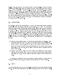
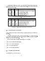
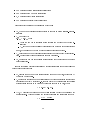
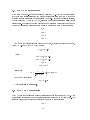
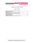
As an example of process switch in small real-time systems a simple case was analyzed
for the studied processors. A real-time system with ten runable processes was considered.
9
Processor
Freq.
Total Time
(MHz) (mikro seconds)
MC88100
25
12.2
I80960KB
25
21.4
Am29000
40
13.1
MIPSR2000 40
6.8
SPARC
40
17.2
T800
30
less than 1
THOR
20
less than 1
Table 1: Total time required for a process switch (estimated)
A complete process switch is assumed accomplished by: storing old process context selecting a new process - load the new process context into processor registers. For THOR
and T800 there is hardware support for rescheduling (as described above) while for the
other processors, process switch was programmed. Table 1 summarises the results [Joh92].
2.4 Real-time system support
As stated earlier, a real-time system should provide means for synchronization between
events. This requires data structures for wait and delay queues and a timer function used
to maintain system time and for process delay purposes. Another important issue is the
problem with synchronizing (local) system time with "global" time, i.e dierent real-time
systems in a distributed environment should be able to use this global time for dierent
purposes. Moreover, the system should provide an accurate delay time for processes that
require it. It should be clear that we are addressing an issue that is dierent from a
conventional real-time clock in a work-station application.
Real-time system software needs careful debugging and testing. Traditionally, processors give support for this through a "trace"-instruction, i.e by executing one machine
instruction at a time and then returning control to some debugging tool. In an event
driven real-time system, a more extensive support would be desirable to catch transient
erronous behaviour resulting from special occurances of events. The environments in which
real-time systems mostly reside and the tasks that they most often perform makes contiguous service or service during operation dicult or impossible to carry out. This makes
hardware debugging facilities and fault-tolerant aspects central in real-time system design.
The following summarize the processor's support for timer facilities, software/hardware
debugging and fault tolerance.
MC88100 can be forced to a "serial mode" (disabling the pipe-line) by setting one
bit in the status register. This, signicantly reduces machine throughput but is useful
for debug purposes. Besides from that, software debugging must be accomplished by the
use of general trap handling facilities. The processor include's comparator circuits at the
output to support fault detection. There are several possible congurations possible for
master/checker operation and other redundant designs.
10
To support debugging systems, the Iapx80960 provides a mechanism for monitoring
processor activity by means of trace events. The processor can be congured to detect
seven dierent trace events, including the instruction execution, branch events, calls, supervisor calls, returns, prereturns and breakpoints. When the processor detects a trace
event, it signals a trace fault and calls a fault handler.
In Am29000 software debug is supported by the trace facility which guarantees exactly
one trap after the execution of any instruction in a program being tested. This allows a
debug routine to follow the execution of instructions, and to determine the state of the
processor and system at the end of each instruction. The processor has a built in timer
facility which can be congured to cause periodic interrupts. The timer facility consists
of 2 special purpose registers , the timer counter and the timer reload registers, which
are accessible only to supervisor mode programs. The timer facility may be used to
perform precise timing of system events. Each Am29000 output has associated logic
which compares the signal on the output with the signal which the processor is providing
internally to the output driver. The processor signals situations where the output of any
enabled driver does not agree with its input. For a single processor, the output comparision
detects short circuits in output signals, but does not detect open circuits. It is possible to
connect a second processor in parallel with the rst, where the second processor has its
outputs disabled due to the Test mode. The second processor detects open-circuit signals,
as well as providing a check of the output of the rst processor.
The R2000 instruction set includes a BREAK instruction which causes a BREAK-trap
to occur. Control is transferred to the applicable system routine.
In SPARC, software debugging is only supported by the means of general trap instructions.
T800 supports software debugging by a variety of instructions that aects status bits.
When the processor Analyze- pin is taken high the processor will halt at a descheduling
point. Consequently the processor oers possibility to respond dierently on interrupts depending on the processor's current mode. T800 incorporate a timer. The implementation
directly supports the "occam" model of time. Each process can have its own independent timer which can be used for internal management or real-time scheduling. Hardware
redundancy is acheived by the means of multiple transputer congurations.
THOR has a built in real-time clock to keep track of system time. Furthermore,
each process has a Delay Register, causing interrupt after a specied delay. This provides
for an ecient implementation of a high level language (real-time) delay function since
kernel software is released from polling a "delay queue" each time a scheduling is to be
performed. Also the TASK-instructions implemented in THOR serves as support for
introducing the ADA-task concept as constituting a process in a real-time system. There
are instructions for scheduling and delaying tasks as well as performing "rendezvous"
between tasks. THOR provides hardware selfcheck as well as an error detection and
correction (EDAC) unit, for check of processor communication with memory, on chip.
11
2.5 Summary
The large register le present in several of the studied processors allows optimizing compilers to arrange for fast subprogram calls by passing parameters in registers. When a
large register le is available there is a good chance that all, or most of, the parameters
could be passed this way. The MC88100 and R2000 are good examples. Both architectures provide large register sets and the usage of these registers could be optimized by
a compiler. The drawback here comes in the case of nested subprogram calls: only the
highest program level can take full advantage of this construction. With a register window
design, as in SPARC or Iapx80960, it is possible to increase the number of program
levels that will benet from parameters passed in registers. However, the fundamental
problem remains since even very large register les may be exhausted. A stack architecture such as T800 or THOR provides a natural convention, stacking of all parameters.
This is simple and straightforward and causes no penalty on nested calls. Furthermore,
with THOR, since the 32 bytes close to top of stack are present in on chip registers it is
possible to take advantage of the rapidness with register passing without having to bother
with save and restore in the case of nested calls. Am29000, nally, provides a solution
similar to SPARC. The large number of registers and the use of a run-time stack made
up by registers could be thought of as register windows where the calling and the called
program share a set of registers.
In hard real/time systems fast rescheduling is of great importance. Process switches in
real-time systems can be a time-consuming matter. Moreover, since processes are created
and removed dynamically it becomes very dicult to predict the time spent on these
activities. In analyzing the processor's ability to perform fast task-switches the important
observations are:
The register le should be reasonably sized since a task-switch (process-switch) re-
quires the entire processor context to be exchanged.
Hardware support for task-switches is an essential feature to reduce the time spent
for rescheduling.
A large register le will delay processor context switch signicantly. Therefore, a
large register le, which has proved essential for increase of system performance could
become a bottleneck with unpredictable consequenses. From above we conclude that a
stack architecture, such as T800 or THOR, with hardware support for process switches
provides considerably better performance than any of the other processors.
In applications where speed is far beyond human control and the tolerances are small
there are often needs for precise time-handling, i.e processes that require a precise delay
should get that delay and nothing else. Three of the studied processors addressed these
issues with on-chip timer facilities: Am29000, T800 and THOR.
Real-time systems are used to maintain surveillance and control processes where a
system failure might have disastrous consequenses: Nuclear plants, aircrafts, spacecrafts
just to mention a few. In the years to come we will see even more applications with
12
steadily growing demands for reliability and security. Consequently hardware/software
debugging support and fault tolerance are also important parts of real-time system design.
All of the processors provide some kind of software debug support. Furthermore T800
provides facilities that makes real-time debugging possible to a limited extent. Builtin fault tolerance support such as selfcheck, memory error detection (and correction) is
provided only by THOR while MC88100 and Am29000 provides support for redundant
designs.
3 Real-time system hardware designs
A physical real-time system, when used in aerospace for example, must meet some important needs. It should be small in size, have low weight and low power consumption.
The system should be reliable and thus only high quality components, at least military
qualied, should be used. Fault tolerance support is desirable and memory errors must
be detected and preferably corrected. (See [Tor90] for a thourougly description of requirements on microcomputers in critical applications.) The purpose with this chapter
is to highlight how demands on system hardware impacts on system performance and
dependability.
This chapter discusses six computer designs that use the Inmos T800 Transputer, the
Saab-Ericsson Space THOR and the Cypress SPARC microprocessors respectively in
order to evaluate hardware aspects of the three processors in two dierent congurations:
A Real-time System application, called the High Dependability Oriented conguration, (HDO). The HDO conguration should be thought of as an on board computer
for a spacecraft.
A general purpose (embedded) system application called the High Speed Oriented
conguration, (HSO).
The designs, which not are realised, are considered comparable at cost and analyzed
to give an estimation of:
maximum possible instruction execution rate
required number of devices
area of printed circuit board
power consumtion
failure rate
13
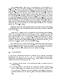
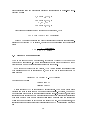
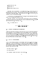
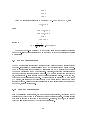
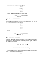
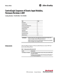
The results are presented in Table 2 and Table 3 and the rest of this chapter briey
describes the method that was used in obtaing these gures. For a thorougly discussion
on this subject see [Joh92].
T800
17.5
4.8
32
10307
5294
3079
THOR
15
8.9
24
7844
5271
2320
SPARC
25
7.5
27
11254
13061
3392
Clock Frequency (MHz)
Mixed instruction execution rate (MmixedIPS)
Number of required devices
Total area for devices (mm2)
Total power requirement (mW)
Failure Intensity (FITS)
Table 2: Summary: real-time system conguration
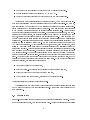
T800
30
8.5
21
7730
26114
119576
THOR
25
14.3
19
8289
26020
104767
SPARC
40
23.0
23
12785
36190
169453
Clock Frequency (MHz)
Mixed instruction execution rate (MmixedIPS)
Number of Required Devices
Total area for devices (mm2)
Total Power Requirement (mW)
Failure Intensity (FITS)
Table 3: Summary: general purpose system conguration
3.1 General notes on the designs
For each design a memory read cycle was analyzed and results were used in the performance
evaluation.
Estimations were performed using worst case assumptions. The designs were optimised for the highest possible clockfrequency i.e no attempt was made to reduce wait state
penalties due to high clock frequence.
For both congurations the following instruction mix was chosen:
50% arithmetical/logical instructions
25% jump/branch instructions
10% load/store instructions
15% oating point instructions
3.2 Execution rate estimation
The instruction mix was made up from:
14
x1 = percentage arithmetical/logical instructions
x2 = percentage jump/branch instructions
x3 = percentage load/store instructions
x4 = percentage oating/point instructions
Parameters that describes the processor in eect were:
X1, the number of processor cycles required to execute an arithmetical/lo-gical in-
struction
X2, composed by:
0:1X21 + 0:9X22 where
{ X21 is the number of processor cycles required for a "branch not taken" instruction
{ X22 is the number of processor cycles required for a "branch taken" instruction
Hence, it was assumed that 90% of all conditional branches are taken.
X3, denotes the number of processor cycles required to execute a load/ store instruction. For simplicity these are considered equal in this sense.
X4, denotes the number of processor cycles required for the execution of a oating
point instruction.
In order to describe wait state penalties and dierent instruction formats the following
parameters were introduced:
W , denotes the number of wait states required for a read bus cycle, determined by
the system conguration.
U , denotes the averages number of instructions that becomes available for execution
as a result of one (32+8 bits) fetch. If, for example 70% of the instruction set consists
of instructions encoded in 16 bits and the rest are encoded in 32 bits, then:
U = 0:7 2 + 0:3 = 1:7
Y (W; U ) denotes the average number of cycles required to feed the processor with
one instruction. This is a function of wait state penalties and instruction format:
Y = 1 + W cycles
U instruction
15
Since instruction fetch and execution is performed simultaneously in a pipe-lined architecture we write:
Z1 = max[X1; Y (W; U )]
Z2 = max[X2; Y (W; U )]
Z3 = X3 + W
Z4 = max[X4; Y (W; U )]
We obtain an expression for the Execution Rate Estimation, ERE :
ERE = Z1 x1 + Z2x2 + Z3x3 + Z4x4(cycles)
where ERE denotes the average number of cycles required to execute one instruction.
Including the cycle time CT in seconds, we arrive at a nal expression for the execution
rate:
ER = ERE1 CT instructions
second
3.3 Memory power consumtion
The memory used in the HDO conguration, (64k nibble) Cypress CY7C194 is a 24 pin
device with 35 ns access time. Memory is organized as 40 bits words (32 data and 8 check
bits) thus each memory access will activate all of the ten devices.
If we dene the Average Memory Activity, (AMA) as the fraction of processor cycles
that accesses memory in an instruction mix, the memory power consumtion could be
estimated as:
Paverage = AMA Pactive + (1 , AMA) Pstandby
For this memory device:
Pactive = 650 mW
Pstandby = 100 mW
Determination of AMA is complicated by several factors. The memory device needs
typically one cycle to enter standby mode after beeing accessed. Obviously, the memory
power requirement depends on the instruction execution order. If, for example, load/store
instructions were ordered as every other instruction rather than consecutive instructions
then there would be more memory "active" cycles since we actually need two consecutive
cycles that do not access memory to reach the "standby" mode. In the estimations, the
instruction order as well as wait state cycles are ignored and AMA is considered a function
of:
16
1. Instruction Fetch Rate
2. Instruction Mix
3. Instruction Execution Timing
Instruction Fetch Rate is limited by the instruction format. For example, with an
instruction format of 32 bits and assuming single cycle execution of all instructions every
cycle needs an instruction fetch. A shorter instruction format, i.e more dense code, will
decrease the need for instruction fetches.
The Instruction Mix is essential since, for example, load/store instructions introduces
extra memory accesses, thus increasing AMA.
Instruction Execution Timing aects memory activity since the fact that all instructions do not execute in one cycle will reduce the need for instruction fetches. Thus the
higher execution times, the lower the AMA.
Here, AMA is estimated by:
AMA = U1 ( Xx1 + Xx2 + Xx3 + Xx4 ) (%)
1
2
3
4
3.4 Notes on the failure rate estimations
Failure rate estimations was carried out according to [Rom]. For temperature acceleration
factor calculation the thermal resistivity factor was used whenever it was available from
manufacturer's documentation. However, since such information was rare, assumptions
had to be made about the junction temperature. For complex circuits, such as CPU:s
and FPU:s, a junction temperature of 110 degrees Celsius was assumed. For all others, a
junction temperature of 80 degrees Celsius was assumed.
3.5 The HDO congurations
The HDO conguration is intended to characterise a space ight on-board computer. It
consists of: CPU, 256 kB of static random access memory, error detection and correction
circuitry, real time clock and glue logic. The designs uses only space qualied components
if nothing else is explicitly said. In the failure rate estimation for HDO conguration the
following assumptions were made:
Quality Factor = S (0.25)
Voltage Factor = 1
Application Environment Factor = Space Flight (0.9)
17
The T800 and SPARC designs both utilise an "error detection and correction unit"
(EDAC). The introduced delay (36 ns, worst case for the EDAC in use) is inserted by the
EDAC control and assures that memory "Ready" signal will not be asserted until correct
data is guaranteed. THOR has a built in EDAC so there was no need for this unit in the
THOR HDO conguration.
3.6 T800 HDO conguration
T800 chip running at 17.5 MHz is available in mil spec. Since the T800 has an on chip
timer, no such peripheral device is required. From the read memory cycle analysis it was
found that three wait states has to be inserted. The following parameters were chosen to
describe the T800 conguration:
X1 = 2
X21 = 2; X22 = 4; X2 = 3:8
X3 = 2
X4 = 8
The manufacturer claims that about 70% of executed instructions are encoded in a
single byte [Inm89] p.195. From the current instruction mix we assume that 50% of the
instructions are encoded in 8 bits, 30% of the instructions are encoded in 16 bits, the rest
are encoded in 32 bits. This gives U = 2 and with W = 3 from above we have:
Y (W; U ) = 2
Thus:
leading to:
Z1 = X1 = 2
Z2 = X2 = 3:8
Z3 = 5
Z4 = X4 = 8
1 = 4:8 MmixedIPS
ER = 3:651 57 ns
For the memory activity we obtain:
AMA = 0:18
which gives: 189 mW/device.
18
3.7 THOR HDO conguration
The THOR has an on-chip timer as well as a built in EDAC. The chip was not available
at the time for this investigation and actual gures concerning the THOR chip were
obtained from simulations in a Genesil Silicon Compiler. According to these simulations,
the clock frequency would be 15 MHz, assuming components satisfying military range
requirements. It was found that one wait state must be inserted during each read memory
cycle and the following parameters were chosen to describe the THOR conguration:
X1 = 1
X2 = 1
X3 = 2
X4 = 4
95% of THOR instructions are encoded in 16 bits, the rest are encoded in 32 bits,
hence U = 1:95 and with W = 1 from above:
Y (W; U ) = 1:03
Thus:
leading to:
Z1 = Y (W; U ) = 1:03
Z2 = Y (W; U ) = 1:03
Z3 = 3
Z4 = X4 = 4
1 = 8:9 MmixedIPS
ER = 1:6731 67 ns
For the memory activity
AMA = 0:410
which gives: 326 mW/device.
3.8 SPARC HDO conguration
The CY7C601 chip available in military specication range is running at 25 MHz. This
conguration requires that two wait states are inserted during a memory read cycle. The
following parameters were chosen to describe the SPARC conguration:
X1 = 1
19
X2 = 1
X3 = 3
X4 = 4
A SPARC instruction is encoded in 32 bits so U = 1. From above W = 2, and:
Y (W; U ) = 3
thus:
leading to
Z1 = Y (W; U ) = 3
Z2 = Y (W; U ) = 3
Z3 = 5
Z4 = X4 = 4
1 = 7:5 MmixedIPS
ER = 3:351 40 ns
The memory power-down facility may not be used since it is not possible to deassert
memory chip-select during interlocks and so the total memory power requirement is 650
mW/device
3.9 The HSO congurations
The HSO conguration is intendeded to estimate peak performance for a general purpose
computer. It consists of a microprocessor with 1 MByte of static random access memory.
The HSO conguration is accomplished by eliminating the EDAC circuitry and changing
the memory devices from the HDO conguration. Glue logic, except from address decoding
and bus buers is implemented using macro cells. The memory is built from eight 64k*16
bit, 25 ns static rams. Since the used memory does not facilitate a "stand-by" power mode,
the memory power requirement is xed. Address decoding is performed by high speed
PAL devices, eliminating any address bus skew which otherwise may arise in high clock
frequency systems. Failure Rate Estimations assumes commercial quality components and
a "Ground, benign" environment.
3.10 T800 HSO conguration
From the T800 read cycle analysis, and with the chosen conguration, we conclude that an
external memory read cycle may be performed without wait state penalty. This also implies
that there is nothing to gain from a cache memory. It should, however, be emphasised
that the T800 internal memory (4 kByte) is not considered.
20
Hence W = 2, U = 2 leading to Y (W; U ) = 1:5 and:
Z1 = 2
Z2 = 3:8
Z3 = 4
Z4 = 8
The HSO T800 conguration runs at 30 MHz and thus:
1 = 8:5 MmixedIPS
ER = 3:551 33 ns
3.11 THOR HSO conguration
In the proposed conguration, THOR (25 MHz) does not require any wait state so:
W = 0, U = 1:95 leading to Y (U; W ) = 0:51 and:
Z1 = 1
Z2 = 1
Z3 = 2
Z4 = 4
nally:
1 = 14:3 MmixedIPS
ER = 1:751 40 ns
3.12 SPARC HSO conguration
The SPARC conguration utilises a 64 kByte cache memory. Experience has shown that
for a cache of this size, a hit rate of 90 % is probable. Denoting a 32-bit word fetched
from the cache Zx (C ) we write:
ERE = (Z1x1 + Z2 x2 + Z3x3 + Z4x4 ) 0:10+
(Z1(C )x1 + Z2 (C )x2 + Z3(C )x3 + Z4(C )x4) 0:9
Timing analysis shows that a cache miss will cost one wait state. An access whithin
cache may be done without wait states. Hence:
21
Z1 = 2
Z2 = 2
Z3 = 4
Z4 = 4
and:
Z1(C ) = 1
Z2(C ) = 1
Z3(C ) = 3
Z4(C ) = 4
The HSO conguration runs at 40 MHz and from this:
1 = 23 MmixedIPS
ER = 1:7351 25 ns
3.13 Summary of results
As shown in table 3, the HSO designs clearly favour SPARC. This is not very suprising
because the SPARC CPU is available in a 40 MHz version and oers an architecture
designed for single cycle execution of instructions. The gures of power requirement and
the required board area indicates the price for this superior performance.
Table 2, however, gives another picture. The restrictions imposed on the real-time
system conguration degrades total SPARC system performance notably. Here it is
comparable with both THOR and T800. The explanation lies in the absence of cache
memory. and the presence of an EDAC which prevents the system from gaining from the
benets that the SPARC architecture oers. At the same time the expected failure rate
and the total board area required are considerably larger than for THOR. The power
requirement more than doubled compared to both T800 and THOR.
3.14 Conclusions
The system hardware considerations indicate that in a real-time system design there is
not very much to gain with a modern, general purpose RISC design. On the contrary,
while the estimated performance for SPARC was just about the level of THOR, the
board area became approximately 40% larger, the power consumption 70% higher and the
expected failure rate became 45 % higher.
22
4 Concluding remarks and Future work
Hard real-time systems are intended for use in environments where dependability is a
primary design goal. Examples of such environments are: spacecraft, aircraft, nuclear
plants and various military applications. It is clear that the probability of a computer
failure causing an accident must be kept as low as possible since any accident in these
contexts very well may cause severe human injuries.
For the majority of common microprocessors, high performance has been the primary
design goal. Most certainly, high performance is desirable even when it comes to hard
real-time systems. However, a primary design goal such as high performance introduces
conicts with a design goal such as dependability. For example, pipelined architectures
and internal cache memories limit the possibility to thoroughly debug real-time software
since the internal processor state may dier from one event of a certain kind to another
event of the same kind. It is also clear that a hard real time system implementation
that utilizes a high performance RISC CPU (such as the Cypress SPARC) does not
necessarily benet from the high execution rate that the microprocessor oers.
Strong dependability requirements imply the need for system predictability. By this we
mean that a faulty behavior that cannot be observed at compile-time (through debugging
or other analysis tools) must not occur during run-time. For such a design, a time triggered
real time system becomes an attractive solution since input, processing and output, are
performed essentially undisturbed by hardware interrupts and is thus time deterministic.
The deterministic behaviour provide means for analyzing the application software for
logical errors as well as for time constraint violations. It might even be possible to develop
methods for proving the correctness of a given application.
It is likely to believe that in the future hard real-time systems will control systems that
further expose people to hazards emerging from computer failures. Automotives is, for
example, such an application. At the same time, however, such a new eld dramatically
changes major presuppositions in hard real-time system design. Manufacturing and maintenance costs must be kept very low without loss of a very high degree of dependability.
Meanwhile, a tremendous number of installed units will insure high volume production
and thus motivate increased costs during design, implementation, integration and test
phases. In particular, the system design and implementation should be paid special attention and a careful, dedicated design should comprise a fault-tolerant hardware solution
as well as an application program development environment. From this example, we may
identify a highly interesting eld for future research and development: A fault-tolerant microprocessor architecture dedicated for use in a safety critical time-triggered hard real-time
system.
23
References
[Adv88] Advanced Micro Devices. Am29000 streamlined instruction processor, 1988.
[Bri93] Bridal et. alt.,. Dacapo: A dependable distributed computer architecture for control of applications with periodic operation. Technical Report 163, Laboratory for
Dependable Computing, Chalmers University of Technology, S-412 96 Goteborg,
1993.
[But93] Buttazzo G.C, Di Natale M. Hartic: A real-time kernel for robot control. Technical report, ARTS Lab, Scuola Superiore S.Anna, Via Carducci, 40 - 56100 Pisa,
Italy, 1993.
[Inm89] Inmos limited. Transputer databook, second edition, 1989.
[Int88] Intel Corporation. 80960KB programmer's reference manual, 1988.
[Joh92] Johansson Roger. Processor performance in real-time systems. Technical Report
136L, Department of Computer Engineering, Chalmers University of Technology,
S-412 96 Goteborg, 1992.
[MIP87] MIPS Computer Systems Inc. MIPS R2000 RISC architecture, 1987.
[Mor93] Morin Magnus. Predictable cyclic computations in autonomous systems: A computational model and implementation. Technical Report 352, Department of
Computer and Information Science, Linkopings University, S-581 83 Linkoping,
1993.
[Mot90] Motorola Inc. MC88100 RISC microprocessor user's manual, second edition,
1990.
[Rom] Rome Air Development Center, Griss AFB, NY 13441/5700. MIL-HDBK-217E,
Military Handbook, Reliability Predictions of Electronic Equipment.
[ROS90] ROSS technology, Inc. SPARC RISC user's guide, 1990.
[Saa92] Saab Ericsson Space. Stack RISC microprocessor instruction set architecture for
prototype chip, 1992.
[Tor90] Torin Jan. Characterisation of microcomputers for embedded real time systems
- directions and basic criteria. Technical Report 100, Department of Computer
Engineering, Chalmers University of Technology, S-412 96 Goteborg, 1990.
[Tor92] Torin Jan. Dependability in complex automotive systems. requirements directions and drivers. Technical Report 128, Department of Computer Engineering,
Chalmers University of Technology, S-412 96 Goteborg, 1992.
[You82] Young S.J. Real Time Languages: Design and Development. Ellis Horwood,
Chichester, 1982.
24