1
PCL 5 Printer LanguageTechnical
Reference Manual
HP Part No. 5961-0509
Printed in USA
First Edition - October 1992
Notice
HEWLETT-PACKARD MAKES NO WARRANTY OF ANY KIND WITH
REGARD TO THIS MATERIAL, INCLUDING, BUT NOT LIMITED TO,
THE IMPLIED WARRANTIES OF MERCHANTABILITY AND
FITNESS FOR A PARTICULAR PURPOSE. Hewlett-Packard shall
not be liable for errors contained herein or for incidental or
consequential damages in connection with the furnishing,
performance, or use of this material.
This document contains proprietary information which is protected by
copyright. All rights are reserved. No part of this document may be
photocopied, reproduced, or translated to another language without
the prior written consent of Hewlett-Packard Company. The
information contained in this document is subject to change without
notice.
ii
EN
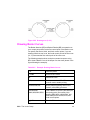
Printing History
This manual was created using HP Tag/Vectra software on an
HP Vectra Personal Computer. The body text is printed in Helvetica
fonts. The camera-ready copy was printed on an HP LaserJet IIISi
printer with Resolution Enhancement technology (REt) and was then
reproduced using standard offset printing.
First Edition – October 1992
NOTICE
This document is the current edition of the technical reference manual for PCL
5 and earlier printers. It replaces the September 1990 edition of the HP PCL 5
Printer Language Technical Reference Manual (p/n 33459-90903). If you have
ordered another PCL Technical Reference document, this manual and the PCL
5 Comparison Guide are the updated replacement documents.
EN
iii
Trademark Credits
Intellifont and Garth Graphic are U.S. registered trademarks of Agfa
Division, Miles Inc. CG Triumvirate and Shannon are trademarks of
Agfa Division, Miles Inc. CG Bodoni, CG Century Schoolbook, CG
Goudy Old Style, CG Melliza, Microstyle, CG Omega, CG Palacio,
CG Times and CG Trump Mediaeval are products of Agfa Division,
Miles Inc. CG Times, a product of Agfa Division, Miles Inc., is based
on Times New Roman, a U.S. registered trademark of Monotype
Corporation plc. PCL, and Vectra are U.S. registered trademarks of
Hewlett-Packard Company. Resolution Enhancement is a trademark
of Hewlett-Packard Company. IBM is a registered trademark of
International Business Machines Corporation. Microsoft, Windows,
and MS-DOS are U.S. registered trademarks of Microsoft
Corporation. TrueType and Macintosh are registered trademarks of
Apple Computer, Inc. PostScript is a registered trademark of Adobe
Systems, Inc. Centronics is a U.S. registered trademark of Centronics
Corporation. ITC Avant Garde Gothic, ITC Benguiat, ITC Bookman,
ITC Cheltenham, ITC Galliard, ITC Korinna, ITC Lubalin Graph, ITC
Souvenir, ITC Zapf Chancery and ITC Zapf Dingbats are U.S.
registered trademarks of International Typeface Corporation. ITC
Tiffany is a trademark of International Typeface Corporation. Futura is
a U.S. registered trademark of Fundicion Tipografica Neufville, S.A.
Serifa is a trademark of Fundicion Tipografica Neufville, S.A. Letraset
is a registered trademark of Esselte Pendaflex Corporation. Revue
and University Roman are trademarks of Esselte Pendaflex
Corporation. Helvetica and Times Roman are trademarks of Linotype
AG and its subsidiaries. Univers is a U.S. registered trademark of
Linotype AG and its subsidiaries. Antique Olive is a trademark of
Monsieur Marcel OLIVE. Arial and Gill Sans are registered
trademarks of The Monotype Corporation plc.
iv
EN
Inside This Manual
What You Can Learn From This Manual
Hewlett-Packard has developed a standard set of printer features for
use in all HP printers. Printer features are accessed through the
corresponding commands of Hewlett-Packard’s PCL language. This
manual describes the PCL 5 printer language. This includes
descriptions of the commands available for Hewlett-Packard PCL 5
LaserJet printers and the basic requirements of PCL language
programming. With the release of new LaserJet family printers there
are new features added which supplement the existing PCL base set.
Features of future printer releases are not covered in this document.
The new features are described in the latest version of the PCL 5
Comparison Guide. Programmers should familiarize themselves with
the information provided in the PCL 5 Comparison Guide in addition
to the information in this document.
Experienced Users
This manual was written for people with some programming
experience. Many of the concept discussions assume some
programming knowledge.
When writing a PCL language program, you should know the PCL
language concepts and commands presented in this manual, and
should be aware of the differences in implementation of the PCL 5
printer language for the various HP LaserJet printers, as described in
the PCL 5 Comparison Guide.
Non-technical Users
Many software applications (word processing software, spreadsheets,
etc.) allow you to embed printer commands as escape sequences in
the body of your documents. This manual presents the full syntax and
explanation of all the commands supported by PCL 5 LaserJet
printers. These commands enable you to take advantage of the
LaserJet printer’s advanced feature set.
EN
v
Note
Since actual implementation of printer commands within software
applications varies from package to package, specific examples are
not given. For examples of printer command usage with many popular
software packages, refer to HP’s Software Application Notes,
provided with the printer. The most current versions of software
application notes can be obtained through the HP Forum on
CompuServe, by fax using the HP FIRST fax service, or through
HP’s literature distribution. Refer to Appendix A for more information.
Chapter Summaries
A brief description of each chapter is provided below.
Chapter 1 - Introduction to HP PCL
This chapter gives a brief history of the development of the PCL
language, describes the PCL language levels (architecture), and
describes the PCL command structure (control codes and escape
sequences).
Chapter 2 - The Page
This chapter introduces the idea of the logical page and identifies the
area in which printing can occur. It also describes the PCL coordinate
system and the HP-GL/2 picture frame.
Chapter - The Print Environment
This chapter introduces the printer’s feature settings, collectively, as
the print environment. It includes descriptions of the factory default
environment, user default environment, and the modified print
environment. The effect of printer reset functions is also described.
Chapter 4 - PCL Job Control Commands
This chapter describes the commands which provide job control.
Job control commands are usually grouped together and sent at the
beginning of a job. Job control includes restoration of the User Default
Environment, selection of the number of copies of each page to be
printed, duplex print commands, and unit of measure specification.
vi
EN
Chapter 5 - Page Control Commands
This chapter describes the commands providing page format control.
Page format control allows you to select the page source, size,
orientation, margins, and text spacing.
Chapter 6 - Cursor Positioning
This chapter describes how to position the cursor within the logical
page.
Chapter 7 - Fonts
This chapter describes basic font information including font
characteristics.
Chapter 8 - PCL Font Selection
This chapter describes how to select a font for printing using the font
characteristics commands. The underline feature is described at the
end of the chapter.
Chapter 9 - Font Management
This chapter describes font management which provides
mechanisms for downloading and manipulating soft fonts.
Chapter 10 - User-Defined Symbol Sets
This chapter describes the capability of some PCL 5 printers to
enable users to define their own symbol sets for special needs.
Chapter 11 - Soft Font Creation
This chapter describes how to organize font/character data for
downloading to the printer.
Chapter 12 - Macros
This chapter describes macro commands which store a block of PCL
commands and data which can be used repeatedly without redefining
the block. The macro function reduces the number of commands that
must be sent to the printer.
EN
vii
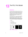
Chapter 13 - The PCL Print Model
This chapter describes the PCL print model which allows for special
effects when printing.
Chapter 14 - PCL Rectangular Area Fill Graphics
This chapter describes how to define and fill a rectangular area with
one of the predefined PCL patterns, or with a user-defined pattern.
Chapter 15 - Raster Graphics
This chapter describes how to download raster graphics to the printer,
and includes various techniques for reducing the amount of data
needed to define the raster image.
Chapter 16 - Status Readback
This chapter describes the PCL status readback features. Status
readback enables you to obtain PCL status information from the
printer, such as: available printer (user) memory, a list of fonts and
symbol sets, and the ID numbers of macros and user-defined
patterns.
Chapter 17 - An Introduction to HP-GL/2 Vector
Graphics
This chapter introduces basic information for HP-GL/2. It lists the
vector graphics commands, and describes the HP-GL/2 command
syntax. An overview of several important topics is also provided, such
as the PCL Picture Frame concept, scaling, pen status and location,
and absolute vs. relative pen movement.
Chapter 18 - The Picture Frame
This chapter describes how to set up an area on the page for printing
vector graphics (the PCL Picture Frame). It discuses the commands
necessary to define and position the picture frame, along with the
commands used to enter and exit HP-GL/2 mode.
viii
EN
Chapter 19 - The Configuration and Status Group
This chapter describes the commands used to set default conditions
and values for programmable HP-GL/2 features. It also explains the
commands used for scaling, establishing a soft-clip window, and
rotating the HP-GL/2 coordinate system.
Chapter 20 - The Vector Group
This chapter provides information about pen movement and drawing
lines, arcs, and circles. It also covers a way to encode coordinates for
increased print speed.
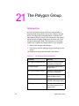
Chapter 21 - The Polygon Group
This chapter explains the polygon mode and how it is used to draw
polygons, subpolygons and circles. The commands for drawing and
filling wedges and rectangles are also described in this chapter.
Chapter 22 - The Line and Fill Attributes Group
This chapter describes the commands used to vary the line types and
fill patterns used to create HP-GL/2 graphics.
Chapter 23 - The Character Group
This chapter contains information about the commands used to print
text (labels) in HP-GL/2 mode. This allows you to print HP-GL/2 labels
in almost any size, slant and direction using proportional or
fixed-spaced scalable fonts.
Chapter 24 - Programming Hints
This chapter provides programming information for use during the
development of PCL software.
EN
ix
Related Documentation
The following related manuals provide further information about
HP LaserJet printers, including their features and functions.
PCL 5 Comparison Guide
This document contains supplemental information for programming
PCL 5 LaserJet printers. It identifies how different HP PCL 5 LaserJet
printers implement the commands described in the HP PCL 5 Printer
Language Technical Reference Manual. It provides printer-specific
information on feature sets, paper handling, fonts, and the printer’s
control panel.
Intellifont Scalable Typeface Format
This document provides information for designing scalable fonts using
Agfa’s Font Access Interchange Standard (FAIS). This document can
be obtained from Agfa Division, Miles Inc. by writing to the address
below or by phone.
Agfa Division, Miles Inc.
Typographic Systems
OEM Technical Support
90 Industrial Way
Wilmington, MA 01887
(508) 658-5600
TrueType Font Files
This document, which provides information for designing scalable
fonts using Microsoft Corporation’s TrueType font scaling technology
has been made available in downloadable form on both CompuServe
and Internet. Contact Microsoft Corporation for details.
x
EN
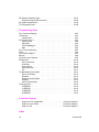
Contents
Notice . . . . . . . . . . . . . . . . . . . . . . . . . . . . . . . . . . . . . . . . . . . . . . . . . . . . . . . . . . ii
Printing History . . . . . . . . . . . . . . . . . . . . . . . . . . . . . . . . . . . . . . . . . . . . . . . . . . . iii
Trademark Credits . . . . . . . . . . . . . . . . . . . . . . . . . . . . . . . . . . . . . . . . . . . . . . . . .iv
Inside This Manual . . . . . . . . . . . . . . . . . . . . . . . . . . . . . . . . . . . . . . . . . . . . . . . . v
What You Can Learn From This Manual . . . . . . . . . . . . . . . . . . . . . . . . . . . . . v
Related Documentation. . . . . . . . . . . . . . . . . . . . . . . . . . . . . . . . . . . . . . . . . . . . . x
PCL 5 Comparison Guide. . . . . . . . . . . . . . . . . . . . . . . . . . . . . . . . . . . . . . . . x
Intellifont Scalable Typeface Format . . . . . . . . . . . . . . . . . . . . . . . . . . . . . . . . x
TrueType Font Files. . . . . . . . . . . . . . . . . . . . . . . . . . . . . . . . . . . . . . . . . . . . . x
Introduction to
HP PCL
PCL Printer Language Architecture . . . . . . . . . . . . . . . . . . . . . . . . . . . . . . . . .
What are Printer Commands?. . . . . . . . . . . . . . . . . . . . . . . . . . . . . . . . . . . . . .
Control Codes. . . . . . . . . . . . . . . . . . . . . . . . . . . . . . . . . . . . . . . . . . . . . . .
PCL Commands . . . . . . . . . . . . . . . . . . . . . . . . . . . . . . . . . . . . . . . . . . . . .
HP-GL/2 Commands . . . . . . . . . . . . . . . . . . . . . . . . . . . . . . . . . . . . . . . . .
PJL Commands . . . . . . . . . . . . . . . . . . . . . . . . . . . . . . . . . . . . . . . . . . . . .
Syntax of Escape Sequences . . . . . . . . . . . . . . . . . . . . . . . . . . . . . . . . . . . . . .
Two-Character Escape Sequences. . . . . . . . . . . . . . . . . . . . . . . . . . . . . . .
Parameterized Escape Sequences. . . . . . . . . . . . . . . . . . . . . . . . . . . . . . .
1-2
1-3
1-3
1-3
1-4
1-4
1-5
1-5
1-6
The Page
Logical Page . . . . . . . . . . . . . . . . . . . . . . . . . . . . . . . . . . . . . . . . . . . . . . . . . . .
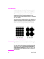
Printed Dots . . . . . . . . . . . . . . . . . . . . . . . . . . . . . . . . . . . . . . . . . . . . . . . . . . .
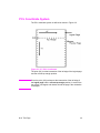
PCL Coordinate System . . . . . . . . . . . . . . . . . . . . . . . . . . . . . . . . . . . . . . . . . .
Units of the PCL Coordinate System. . . . . . . . . . . . . . . . . . . . . . . . . . . . . . . . .
PCL Units . . . . . . . . . . . . . . . . . . . . . . . . . . . . . . . . . . . . . . . . . . . . . . . . . .
Decipoints . . . . . . . . . . . . . . . . . . . . . . . . . . . . . . . . . . . . . . . . . . . . . . . . . .
Columns & Rows . . . . . . . . . . . . . . . . . . . . . . . . . . . . . . . . . . . . . . . . . . . .
Printer Internal Units . . . . . . . . . . . . . . . . . . . . . . . . . . . . . . . . . . . . . . . . . .
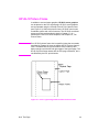
HP-GL/2 Picture Frame . . . . . . . . . . . . . . . . . . . . . . . . . . . . . . . . . . . . . . . . . . .
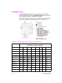
Printable Area . . . . . . . . . . . . . . . . . . . . . . . . . . . . . . . . . . . . . . . . . . . . . . . . . .
EN
2-2
2-3
2-4
2-5
2-5
2-5
2-5
2-5
2-6
2-7
Contents-1
The Print Environment
Factory Default Environment . . . . . . . . . . . . . . . . . . . . . . . . . . . . . . . . . . . . . . .
User Default Environment . . . . . . . . . . . . . . . . . . . . . . . . . . . . . . . . . . . . . . . . .
Modified Print Environment . . . . . . . . . . . . . . . . . . . . . . . . . . . . . . . . . . . . . . . .
Resetting the Print Environment . . . . . . . . . . . . . . . . . . . . . . . . . . . . . . . . . . . .
Printer Reset. . . . . . . . . . . . . . . . . . . . . . . . . . . . . . . . . . . . . . . . . . . . . . . .
Cold Reset . . . . . . . . . . . . . . . . . . . . . . . . . . . . . . . . . . . . . . . . . . . . . . . . .
3-2
3-6
3-7
3-8
3-8
3-9
PCL Job Control Commands
Printer Reset Command . . . . . . . . . . . . . . . . . . . . . . . . . . . . . . . . . . . . . . . . . . 4-2
Universal Exit Language Command . . . . . . . . . . . . . . . . . . . . . . . . . . . . . . . . . 4-3
Number of Copies Command . . . . . . . . . . . . . . . . . . . . . . . . . . . . . . . . . . . . . . 4-4
Simplex/Duplex Print Command . . . . . . . . . . . . . . . . . . . . . . . . . . . . . . . . . . . . 4-5
Left Offset Registration Command . . . . . . . . . . . . . . . . . . . . . . . . . . . . . . . . . . 4-7
Top Offset Registration Command . . . . . . . . . . . . . . . . . . . . . . . . . . . . . . . . . . 4-8
Duplex Page Side Selection Command . . . . . . . . . . . . . . . . . . . . . . . . . . . . . 4-10
Job Separation Command. . . . . . . . . . . . . . . . . . . . . . . . . . . . . . . . . . . . . . . . 4-11
Output Bin Selection Command . . . . . . . . . . . . . . . . . . . . . . . . . . . . . . . . . . . 4-12
Unit of Measure Command . . . . . . . . . . . . . . . . . . . . . . . . . . . . . . . . . . . . . . . 4-13
Page Control Commands
Page Size Command. . . . . . . . . . . . . . . . . . . . . . . . . . . . . . . . . . . . . . . . . . . . . 5-2
PAPER SOURCE COMMAND . . . . . . . . . . . . . . . . . . . . . . . . . . . . . . . . . . . . . 5-4
Logical Page Orientation Command . . . . . . . . . . . . . . . . . . . . . . . . . . . . . . . . . 5-5
Print Direction Command . . . . . . . . . . . . . . . . . . . . . . . . . . . . . . . . . . . . . . . . . 5-9
Text Area . . . . . . . . . . . . . . . . . . . . . . . . . . . . . . . . . . . . . . . . . . . . . . . . . . . . . 5-11
Left Margin Command. . . . . . . . . . . . . . . . . . . . . . . . . . . . . . . . . . . . . . . . . . . 5-13
Right Margin Command . . . . . . . . . . . . . . . . . . . . . . . . . . . . . . . . . . . . . . . . . 5-14
Clear Horizontal Margins Command . . . . . . . . . . . . . . . . . . . . . . . . . . . . . . . . 5-15
Top Margin Command . . . . . . . . . . . . . . . . . . . . . . . . . . . . . . . . . . . . . . . . . . . 5-16
Text Length Command . . . . . . . . . . . . . . . . . . . . . . . . . . . . . . . . . . . . . . . . . . 5-18
Perforation Skip Command . . . . . . . . . . . . . . . . . . . . . . . . . . . . . . . . . . . . . . . 5-19
Horizontal Motion Index (HMI) Command . . . . . . . . . . . . . . . . . . . . . . . . . . . . 5-20
Vertical Motion Index (VMI) Command . . . . . . . . . . . . . . . . . . . . . . . . . . . . . . 5-22
Common VMI Settings . . . . . . . . . . . . . . . . . . . . . . . . . . . . . . . . . . . . . . . 5-23
Line Spacing Command . . . . . . . . . . . . . . . . . . . . . . . . . . . . . . . . . . . . . . . . . 5-24
Contents-2
EN
Cursor Positioning
Absolute vs. Relative Cursor Positioning
. . . . . . . . . . . . . . . . . . . . . . . . . . . 6-2
Cursor Positioning Units
. . . . . . . . . . . . . . . . . . . . . . . . . . . . . . . . . . . . . 6-3
PCL Units . . . . . . . . . . . . . . . . . . . . . . . . . . . . . . . . . . . . . . . . . . . . . . . . . . 6-3
Decipoints . . . . . . . . . . . . . . . . . . . . . . . . . . . . . . . . . . . . . . . . . . . . . . . . 6-4
Columns & Rows . . . . . . . . . . . . . . . . . . . . . . . . . . . . . . . . . . . . . . . . . . . 6-4
Horizontal Cursor Positioning (Columns) Command. . . . . . . . . . . . . . . . . . . . . 6-5
Horizontal Cursor Positioning (Decipoints) Command
. . . . . . . . . . . . . . . . 6-6
Horizontal Cursor Positioning (PCL Units) Command. . . . . . . . . . . . . . . . . . . . 6-7
Horizontal Cursor Positioning Control Codes . . . . . . . . . . . . . . . . . . . . . . . . . . 6-8
CR - Carriage Return . . . . . . . . . . . . . . . . . . . . . . . . . . . . . . . . . . . . . . . . . 6-8
SP - Space . . . . . . . . . . . . . . . . . . . . . . . . . . . . . . . . . . . . . . . . . . . . . . . . . 6-8
BS - Backspace . . . . . . . . . . . . . . . . . . . . . . . . . . . . . . . . . . . . . . . . . . . . . 6-9
HT - Horizontal Tab . . . . . . . . . . . . . . . . . . . . . . . . . . . . . . . . . . . . . . . . . . 6-9
Vertical Cursor Positioning (Rows) Command . . . . . . . . . . . . . . . . . . . . . . . . 6-10
Vertical Cursor Positioning (Decipoints) Command
. . . . . . . . . . . . . . . . . . 6-11
Vertical Cursor Positioning (PCL Units) Command
. . . . . . . . . . . . . . . . . . 6-12
Half-Line Feed Command . . . . . . . . . . . . . . . . . . . . . . . . . . . . . . . . . . . . . . 6-13
Vertical Cursor Positioning Control Codes . . . . . . . . . . . . . . . . . . . . . . . . . . . 6-13
LF - Line Feed. . . . . . . . . . . . . . . . . . . . . . . . . . . . . . . . . . . . . . . . . . . . . . 6-13
FF - Form Feed. . . . . . . . . . . . . . . . . . . . . . . . . . . . . . . . . . . . . . . . . . . . . 6-13
Line Termination Command . . . . . . . . . . . . . . . . . . . . . . . . . . . . . . . . . . . . . . 6-14
Push/Pop Cursor Position Command . . . . . . . . . . . . . . . . . . . . . . . . . . . . . . . 6-15
Fonts
Font Sources . . . . . . . . . . . . . . . . . . . . . . . . . . . . . . . . . . . . . . . . . . . . . . 7-2
Symbol Set . . . . . . . . . . . . . . . . . . . . . . . . . . . . . . . . . . . . . . . . . . . . . . . . . . . 7-3
Spacing
. . . . . . . . . . . . . . . . . . . . . . . . . . . . . . . . . . . . . . . . . . . . . . . . . . . . 7-4
Pitch
. . . . . . . . . . . . . . . . . . . . . . . . . . . . . . . . . . . . . . . . . . . . . . . . . . . . . . . 7-5
Height
. . . . . . . . . . . . . . . . . . . . . . . . . . . . . . . . . . . . . . . . . . . . . . . . . . . . . . 7-5
Style
. . . . . . . . . . . . . . . . . . . . . . . . . . . . . . . . . . . . . . . . . . . . . . . . . . . . . 7-6
Stroke Weight
. . . . . . . . . . . . . . . . . . . . . . . . . . . . . . . . . . . . . . . . . . . . . . . . 7-6
Typeface Family . . . . . . . . . . . . . . . . . . . . . . . . . . . . . . . . . . . . . . . . . . . . . . . 7-7
Orientation
. . . . . . . . . . . . . . . . . . . . . . . . . . . . . . . . . . . . . . . . . . . . . . . . . . 7-8
Bitmap Fonts and Scalable Typefaces
. . . . . . . . . . . . . . . . . . . . . . . . . . . . 7-9
Internal Fonts . . . . . . . . . . . . . . . . . . . . . . . . . . . . . . . . . . . . . . . . . . . . . . . . 7-11
Special Effects . . . . . . . . . . . . . . . . . . . . . . . . . . . . . . . . . . . . . . . . . . . . . . . 7-11
EN
Contents-3
PCL Font Selection
Primary and Secondary Fonts. . . . . . . . . . . . . . . . . . . . . . . . . . . . . . . . . . . . . . 8-5
Font Resolution . . . . . . . . . . . . . . . . . . . . . . . . . . . . . . . . . . . . . . . . . . . . . . . . . 8-5
Symbol Set Command . . . . . . . . . . . . . . . . . . . . . . . . . . . . . . . . . . . . . . . . . . . 8-6
Example . . . . . . . . . . . . . . . . . . . . . . . . . . . . . . . . . . . . . . . . . . . . . . . . . . . 8-7
7-bit ISO Symbol Sets . . . . . . . . . . . . . . . . . . . . . . . . . . . . . . . . . . . . . . . 8-8
Spacing Command . . . . . . . . . . . . . . . . . . . . . . . . . . . . . . . . . . . . . . . . . . . . . . 8-9
Example . . . . . . . . . . . . . . . . . . . . . . . . . . . . . . . . . . . . . . . . . . . . . . . . . . . 8-9
Pitch Command. . . . . . . . . . . . . . . . . . . . . . . . . . . . . . . . . . . . . . . . . . . . . . . . 8-10
Example . . . . . . . . . . . . . . . . . . . . . . . . . . . . . . . . . . . . . . . . . . . . . . . . . . 8-11
Height Command . . . . . . . . . . . . . . . . . . . . . . . . . . . . . . . . . . . . . . . . . . . . . . 8-12
Example . . . . . . . . . . . . . . . . . . . . . . . . . . . . . . . . . . . . . . . . . . . . . . . . . . 8-13
Style Command. . . . . . . . . . . . . . . . . . . . . . . . . . . . . . . . . . . . . . . . . . . . . . . . 8-14
Example . . . . . . . . . . . . . . . . . . . . . . . . . . . . . . . . . . . . . . . . . . . . . . . . . . 8-15
Stroke Weight Command . . . . . . . . . . . . . . . . . . . . . . . . . . . . . . . . . . . . . . . . 8-16
Example . . . . . . . . . . . . . . . . . . . . . . . . . . . . . . . . . . . . . . . . . . . . . . . . . . 8-17
Typeface Family Command . . . . . . . . . . . . . . . . . . . . . . . . . . . . . . . . . . . . . . . 8-18
Example . . . . . . . . . . . . . . . . . . . . . . . . . . . . . . . . . . . . . . . . . . . . . . . . . . 8-19
Orientation. . . . . . . . . . . . . . . . . . . . . . . . . . . . . . . . . . . . . . . . . . . . . . . . . . . . 8-20
Font Selection Examples. . . . . . . . . . . . . . . . . . . . . . . . . . . . . . . . . . . . . . . . . 8-21
Bitmap, Fixed-Spaced Font. . . . . . . . . . . . . . . . . . . . . . . . . . . . . . . . . . . . 8-21
Scalable, Proportional-Spaced Font . . . . . . . . . . . . . . . . . . . . . . . . . . . . . 8-22
Summary of Font Selection by Characteristic . . . . . . . . . . . . . . . . . . . . . . . . . 8-23
Font Selectionby ID Command . . . . . . . . . . . . . . . . . . . . . . . . . . . . . . . . . . . . 8-26
Examples . . . . . . . . . . . . . . . . . . . . . . . . . . . . . . . . . . . . . . . . . . . . . . . . . 8-27
Select Default Font Command . . . . . . . . . . . . . . . . . . . . . . . . . . . . . . . . . . . . 8-27
HP-GL/2 Font Selection . . . . . . . . . . . . . . . . . . . . . . . . . . . . . . . . . . . . . . . . . 8-27
Transparent Print Data Command. . . . . . . . . . . . . . . . . . . . . . . . . . . . . . . . . . 8-28
Example . . . . . . . . . . . . . . . . . . . . . . . . . . . . . . . . . . . . . . . . . . . . . . . . . . 8-28
Underline Command . . . . . . . . . . . . . . . . . . . . . . . . . . . . . . . . . . . . . . . . . . . . 8-29
Font Management
Downloading Soft Fonts . . . . . . . . . . . . . . . . . . . . . . . . . . . . . . . . . . . . . . . . . .
Temporary vs. Permanent Fonts . . . . . . . . . . . . . . . . . . . . . . . . . . . . . . . . . . . .
Deleting Fonts . . . . . . . . . . . . . . . . . . . . . . . . . . . . . . . . . . . . . . . . . . . . . . . . . .
Font ID Command . . . . . . . . . . . . . . . . . . . . . . . . . . . . . . . . . . . . . . . . . . . . . . .
Example . . . . . . . . . . . . . . . . . . . . . . . . . . . . . . . . . . . . . . . . . . . . . . . . . . .
Font Control Command . . . . . . . . . . . . . . . . . . . . . . . . . . . . . . . . . . . . . . . . . . .
Examples . . . . . . . . . . . . . . . . . . . . . . . . . . . . . . . . . . . . . . . . . . . . . . . . . .
Font Management Example . . . . . . . . . . . . . . . . . . . . . . . . . . . . . . . . . . . . . . .
Unbound Scalable Fonts . . . . . . . . . . . . . . . . . . . . . . . . . . . . . . . . . . . . . . . . . .
Bound and Unbound Fonts . . . . . . . . . . . . . . . . . . . . . . . . . . . . . . . . . . . . .
Font Selection and Unbound Fonts . . . . . . . . . . . . . . . . . . . . . . . . . . . . . .
Contents-4
9-2
9-3
9-3
9-4
9-4
9-5
9-5
9-7
9-8
9-8
9-8
EN
User-Defined Symbol Sets
Symbol Set ID Code Command . . . . . . . . . . . . . . . . . . . . . . . . . . . . . . . . . . . 10-2
Define Symbol Set. . . . . . . . . . . . . . . . . . . . . . . . . . . . . . . . . . . . . . . . . . . . . . 10-4
Header Size (UI) . . . . . . . . . . . . . . . . . . . . . . . . . . . . . . . . . . . . . . . . . . . . 10-5
Encoded Symbol Set Designator (UI)
. . . . . . . . . . . . . . . . . . . . . . . . . 10-6
Format (UB) . . . . . . . . . . . . . . . . . . . . . . . . . . . . . . . . . . . . . . . . . . . . . . . 10-6
Symbol Set Type (UB) . . . . . . . . . . . . . . . . . . . . . . . . . . . . . . . . . . . . . . . 10-6
First Code (UI) . . . . . . . . . . . . . . . . . . . . . . . . . . . . . . . . . . . . . . . . . . . . . 10-7
Last Code (UI) . . . . . . . . . . . . . . . . . . . . . . . . . . . . . . . . . . . . . . . . . . . . . 10-7
Character Requirements (Array of UB) and character requirement . . . . 10-7
Symbol Map (Array of UI) . . . . . . . . . . . . . . . . . . . . . . . . . . . . . . . . . . . 10-11
Symbol Set Control Command . . . . . . . . . . . . . . . . . . . . . . . . . . . . . . . . . . . 10-12
User-Defined Symbol Set Examples . . . . . . . . . . . . . . . . . . . . . . . . . . . . . . 10-13
Unicode Symbol Index Example . . . . . . . . . . . . . . . . . . . . . . . . . . . . . . . 10-13
MSL Symbol Index Example . . . . . . . . . . . . . . . . . . . . . . . . . . . . . . . . . 10-14
Soft Font Creation
Font Classifications
. . . . . . . . . . . . . . . . . . . . . . . . . . . . . . . . . . . . . . . 11-2
Coordinate System . . . . . . . . . . . . . . . . . . . . . . . . . . . . . . . . . . . . . . . . . . . . . 11-4
Bitmap Fonts . . . . . . . . . . . . . . . . . . . . . . . . . . . . . . . . . . . . . . . . . . . . . . 11-4
Intellifont Scalable Fonts . . . . . . . . . . . . . . . . . . . . . . . . . . . . . . . . . . . . 11-4
TrueType Scalable Fonts
. . . . . . . . . . . . . . . . . . . . . . . . . . . . . . . . . . . 11-5
Font Header Command. . . . . . . . . . . . . . . . . . . . . . . . . . . . . . . . . . . . . . . . . . 11-6
Font Header Format . . . . . . . . . . . . . . . . . . . . . . . . . . . . . . . . . . . . . . . . . . . . 11-6
Data Types . . . . . . . . . . . . . . . . . . . . . . . . . . . . . . . . . . . . . . . . . . . . . . . 11-14
Font Descriptor Size (UI) . . . . . . . . . . . . . . . . . . . . . . . . . . . . . . . . . . . . 11-15
Header Format (UB) . . . . . . . . . . . . . . . . . . . . . . . . . . . . . . . . . . . . . . . 11-15
Font Type (UB) . . . . . . . . . . . . . . . . . . . . . . . . . . . . . . . . . . . . . . . . . . . 11-15
Style MSB (UI)
. . . . . . . . . . . . . . . . . . . . . . . . . . . . . . . . . . . . . . . . . . 11-16
Baseline Position (UI) . . . . . . . . . . . . . . . . . . . . . . . . . . . . . . . . . . . . . . 11-18
Cell Width (UI) . . . . . . . . . . . . . . . . . . . . . . . . . . . . . . . . . . . . . . . . . . . 11-18
Cell Height (UI) . . . . . . . . . . . . . . . . . . . . . . . . . . . . . . . . . . . . . . . . . . . 11-18
Orientation (UB) . . . . . . . . . . . . . . . . . . . . . . . . . . . . . . . . . . . . . . . . . 11-19
Spacing (B) . . . . . . . . . . . . . . . . . . . . . . . . . . . . . . . . . . . . . . . . . . . . . . 11-20
Symbol Set (UI)
. . . . . . . . . . . . . . . . . . . . . . . . . . . . . . . . . . . . . . . . . 11-20
Pitch (UI) . . . . . . . . . . . . . . . . . . . . . . . . . . . . . . . . . . . . . . . . . . . . . . . 11-21
Height (UI) . . . . . . . . . . . . . . . . . . . . . . . . . . . . . . . . . . . . . . . . . . . . . . . 11-22
xHeight (UI) . . . . . . . . . . . . . . . . . . . . . . . . . . . . . . . . . . . . . . . . . . . . . . 11-22
Width Type (SB) . . . . . . . . . . . . . . . . . . . . . . . . . . . . . . . . . . . . . . . . . . 11-23
Style LSB (UB) . . . . . . . . . . . . . . . . . . . . . . . . . . . . . . . . . . . . . . . . . . . 11-23
Stroke Weight (SB) . . . . . . . . . . . . . . . . . . . . . . . . . . . . . . . . . . . . . . . . 11-23
Typeface (UB)
. . . . . . . . . . . . . . . . . . . . . . . . . . . . . . . . . . . . . . . . 11-24
Serif Style (UB) . . . . . . . . . . . . . . . . . . . . . . . . . . . . . . . . . . . . . . . . . . . 11-27
Quality (UB) . . . . . . . . . . . . . . . . . . . . . . . . . . . . . . . . . . . . . . . . . . . . . . 11-28
Placement (SB) . . . . . . . . . . . . . . . . . . . . . . . . . . . . . . . . . . . . . . . . . . . 11-28
EN
Contents-5
Underline Position (Distance) (SB) . . . . . . . . . . . . . . . . . . . . . . . . . . . . .
Underline Thickness (UB) . . . . . . . . . . . . . . . . . . . . . . . . . . . . . . . . . . . .
Text Height (UI) . . . . . . . . . . . . . . . . . . . . . . . . . . . . . . . . . . . . . . . . . . .
Text Width (UI) . . . . . . . . . . . . . . . . . . . . . . . . . . . . . . . . . . . . . . . . . . . .
First Code (UI) . . . . . . . . . . . . . . . . . . . . . . . . . . . . . . . . . . . . . . . . . . . .
Last Code / Number of Characters (UI) . . . . . . . . . . . . . . . . . . . . . . . . .
Pitch Extended (UB) . . . . . . . . . . . . . . . . . . . . . . . . . . . . . . . . . . . . . . . .
Height Extended (UB). . . . . . . . . . . . . . . . . . . . . . . . . . . . . . . . . . . . . . .
Cap Height (UI). . . . . . . . . . . . . . . . . . . . . . . . . . . . . . . . . . . . . . . . . . . .
Font Number (ULI) . . . . . . . . . . . . . . . . . . . . . . . . . . . . . . . . . . . . . . . . .
Font Name (ASC16) . . . . . . . . . . . . . . . . . . . . . . . . . . . . . . . . . . . . . .
X Resolution (UI) . . . . . . . . . . . . . . . . . . . . . . . . . . . . . . . . . . . . . . . . . .
Y Resolution (UI) . . . . . . . . . . . . . . . . . . . . . . . . . . . . . . . . . . . . . . . . . .
Scale Factor (UI) . . . . . . . . . . . . . . . . . . . . . . . . . . . . . . . . . . . . . . . . . .
Master Underline Position (SI) . . . . . . . . . . . . . . . . . . . . . . . . . . . . . . .
Master Underline Thickness (Height) (UI) . . . . . . . . . . . . . . . . . . . . . .
Font Scaling Technology (UB) . . . . . . . . . . . . . . . . . . . . . . . . . . . . . . .
Variety (UB) . . . . . . . . . . . . . . . . . . . . . . . . . . . . . . . . . . . . . . . . . . . . .
OR Threshold (UI) . . . . . . . . . . . . . . . . . . . . . . . . . . . . . . . . . . . . . . . .
Global Italic Angle (SI) . . . . . . . . . . . . . . . . . . . . . . . . . . . . . . . . . . . . . .
Global Intellifont Data Size (UI) . . . . . . . . . . . . . . . . . . . . . . . . . . . . . . .
Global Intellifont Data . . . . . . . . . . . . . . . . . . . . . . . . . . . . . . . . . . . . . .
Character Complement (Array of UB) . . . . . . . . . . . . . . . . . . . . . . . . .
Checksum . . . . . . . . . . . . . . . . . . . . . . . . . . . . . . . . . . . . . . . . . . . . . . .
Copyright . . . . . . . . . . . . . . . . . . . . . . . . . . . . . . . . . . . . . . . . . . . . . . .
Segmented Font Data (Format 15) . . . . . . . . . . . . . . . . . . . . . . . . . . . .
Font Header Examples . . . . . . . . . . . . . . . . . . . . . . . . . . . . . . . . . . . . . . . . .
Character Definitions. . . . . . . . . . . . . . . . . . . . . . . . . . . . . . . . . . . . . . . . . . .
Character Code Command . . . . . . . . . . . . . . . . . . . . . . . . . . . . . . . . . . . . . .
Character Definition Command . . . . . . . . . . . . . . . . . . . . . . . . . . . . . . . . . . .
Character Descriptor Formats . . . . . . . . . . . . . . . . . . . . . . . . . . . . . . . . . . . .
Character Descriptor and Data Format for PCL Bitmap Fonts . . . . . .
Character Descriptor and Data Format for Intellifont Scalable Fonts . . .
Character Descriptor and Data Format for TrueType Fonts . . . . . . . . . .
Character Definition Examples . . . . . . . . . . . . . . . . . . . . . . . . . . . . . . . . . . .
11-29
11-29
11-29
11-29
11-30
11-30
11-30
11-31
11-31
11-32
11-33
11-33
11-34
11-34
11-34
11-34
11-34
11-35
11-35
11-35
11-35
11-35
11-35
11-39
11-39
11-39
11-43
11-48
11-49
11-50
11-51
11-51
11-60
11-65
11-70
Macros
Macro Creation . . . . . . . . . . . . . . . . . . . . . . . . . . . . . . . . . . . . . . . . . . . . . . . .
Macro Invocation . . . . . . . . . . . . . . . . . . . . . . . . . . . . . . . . . . . . . . . . . . . . . . .
Temporary / Permanent Macros . . . . . . . . . . . . . . . . . . . . . . . . . . . . . . . . . . .
Deleting Macros . . . . . . . . . . . . . . . . . . . . . . . . . . . . . . . . . . . . . . . . . . . . . . .
Macro ID . . . . . . . . . . . . . . . . . . . . . . . . . . . . . . . . . . . . . . . . . . . . . . . . . . . . .
Example . . . . . . . . . . . . . . . . . . . . . . . . . . . . . . . . . . . . . . . . . . . . . . . . . .
Contents-6
12-3
12-4
12-5
12-6
12-6
12-6
EN
Macro Control . . . . . . . . . . . . . . . . . . . . . . . . . . . . . . . . . . . . . . . . . . . . . . . . . 12-7
Example . . . . . . . . . . . . . . . . . . . . . . . . . . . . . . . . . . . . . . . . . . . . . . . . . . 12-8
Macro Control Example. . . . . . . . . . . . . . . . . . . . . . . . . . . . . . . . . . . . . . . . . . 12-9
The PCL Print Model
Command Sequence. . . . . . . . . . . . . . . . . . . . . . . . . . . . . . . . . . . . . . . . . . . . 13-5
Source Transparency Mode Command. . . . . . . . . . . . . . . . . . . . . . . . . . . . . . 13-6
Pattern Transparency Mode Command. . . . . . . . . . . . . . . . . . . . . . . . . . . . . . 13-7
Pattern ID (Area Fill ID) Command . . . . . . . . . . . . . . . . . . . . . . . . . . . . . . . . . 13-8
Select Current Pattern Command . . . . . . . . . . . . . . . . . . . . . . . . . . . . . . . . . 13-12
User-Defined Pattern Graphics . . . . . . . . . . . . . . . . . . . . . . . . . . . . . . . . . . . 13-13
User-Defined Pattern Implementation. . . . . . . . . . . . . . . . . . . . . . . . . . . 13-13
User-Defined Pattern Command . . . . . . . . . . . . . . . . . . . . . . . . . . . . . . . . . . 13-16
Format (Byte 0) . . . . . . . . . . . . . . . . . . . . . . . . . . . . . . . . . . . . . . . . . . . 13-17
Continuation (Byte 1) . . . . . . . . . . . . . . . . . . . . . . . . . . . . . . . . . . . . . . . 13-17
Pixel Encoding (Byte 2) . . . . . . . . . . . . . . . . . . . . . . . . . . . . . . . . . . . . . 13-17
Reserved (Byte 3). . . . . . . . . . . . . . . . . . . . . . . . . . . . . . . . . . . . . . . . . . 13-18
Height in Pixels (Bytes 4 and 5) . . . . . . . . . . . . . . . . . . . . . . . . . . . . . . . 13-18
Width in Pixels (Bytes 6 and 7) . . . . . . . . . . . . . . . . . . . . . . . . . . . . . . . 13-18
Pattern Image . . . . . . . . . . . . . . . . . . . . . . . . . . . . . . . . . . . . . . . . . . . . 13-18
Master X Resolution (UI) . . . . . . . . . . . . . . . . . . . . . . . . . . . . . . . . . . . . 13-18
Master Y Resolution (UI) . . . . . . . . . . . . . . . . . . . . . . . . . . . . . . . . . . . . 13-18
User-defined Pattern Example . . . . . . . . . . . . . . . . . . . . . . . . . . . . . . . . 13-19
Set Pattern Reference Point Command . . . . . . . . . . . . . . . . . . . . . . . . . . . . 13-22
Pattern Control Command. . . . . . . . . . . . . . . . . . . . . . . . . . . . . . . . . . . . . . . 13-23
PCL Rectangular Area Fill Graphics
Rectangular Area Fill Procedure . . . . . . . . . . . . . . . . . . . . . . . . . . . . . . . 14-1
Horizontal Rectangle Size (Decipoints) Command . . . . . . . . . . . . . . . . . . . . . 14-3
Horizontal Rectangle Size (PCL Units) Command . . . . . . . . . . . . . . . . . . . . . 14-3
Vertical Rectangle Size (Decipoints) Command . . . . . . . . . . . . . . . . . . . . . . . 14-4
Vertical Rectangle Size (PCL Units) Command . . . . . . . . . . . . . . . . . . . . . . . 14-4
Pattern ID (Area Fill ID) Command . . . . . . . . . . . . . . . . . . . . . . . . . . . . . . . . . 14-5
Fill Rectangular Area Command . . . . . . . . . . . . . . . . . . . . . . . . . . . . . . . . . . . 14-9
Pattern Transparency for Rectangular Area Fill. . . . . . . . . . . . . . . . . . . . . . . 14-11
Rectangular Area Fill Examples . . . . . . . . . . . . . . . . . . . . . . . . . . . . . . . . . . 14-13
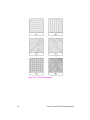
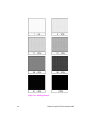
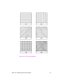
Pre-defined Pattern Examples . . . . . . . . . . . . . . . . . . . . . . . . . . . . . . . . 14-13
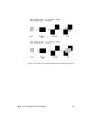
User-defined Pattern Example . . . . . . . . . . . . . . . . . . . . . . . . . . . . . . . . 14-17
Raster Graphics
Raster Graphics Command Sequence . . . . . . . . . . . . . . . . . . . . . . . . . . . . . . 15-4
Raster Graphics Resolution Command. . . . . . . . . . . . . . . . . . . . . . . . . . . . . . 15-6
EN
Contents-7
Raster Graphics Presentation Mode Command . . . . . . . . . . . . . . . . . . . . . . . 15-8
Raster Height Command. . . . . . . . . . . . . . . . . . . . . . . . . . . . . . . . . . . . . . . . 15-11
Raster Width Command . . . . . . . . . . . . . . . . . . . . . . . . . . . . . . . . . . . . . . . . 15-13
Start Raster Graphics Command . . . . . . . . . . . . . . . . . . . . . . . . . . . . . . . . . 15-14
Raster Y Offset Command . . . . . . . . . . . . . . . . . . . . . . . . . . . . . . . . . . . . . . 15-15
Set Compression Method Command . . . . . . . . . . . . . . . . . . . . . . . . . . . . . . 15-16
Unencoded (Method 0) . . . . . . . . . . . . . . . . . . . . . . . . . . . . . . . . . . . . . . 15-16
Run-length Encoding (Method 1) . . . . . . . . . . . . . . . . . . . . . . . . . . . . . . 15-16
Tagged Image File Format Encoding
(Method 2) . . . . . . . . . . . . . . . . . . . . . . . . . . . . . . . . . . . . . . . . . . . 15-17
Delta Row Compression (Method 3) . . . . . . . . . . . . . . . . . . . . . . . . . . 15-20
Example: Delta Row Compression . . . . . . . . . . . . . . . . . . . . . . . . . . . . . 15-24
Adaptive Compression (Method 5) . . . . . . . . . . . . . . . . . . . . . . . . . . . . 15-25
Transfer Raster Data Command . . . . . . . . . . . . . . . . . . . . . . . . . . . . . . . . . . 15-29
End Raster Graphics Command . . . . . . . . . . . . . . . . . . . . . . . . . . . . . . . . . . 15-30
Raster Graphics Example . . . . . . . . . . . . . . . . . . . . . . . . . . . . . . . . . . . . . . . 15-31
Status Readback
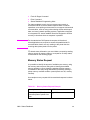
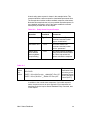
Memory Status Request . . . . . . . . . . . . . . . . . . . . . . . . . . . . . . . . . . . . 16-2
Entity Status
. . . . . . . . . . . . . . . . . . . . . . . . . . . . . . . . . . . . . . . . . . . 16-3
Status Response . . . . . . . . . . . . . . . . . . . . . . . . . . . . . . . . . . . . . . . . . . 16-5
Status Response Syntax . . . . . . . . . . . . . . . . . . . . . . . . . . . . . . . . . . . . . . . . . 16-6
Set Status Readback Location Type Command . . . . . . . . . . . . . . . . . . . . . . . 16-8
Set Status Readback Location Unit Command . . . . . . . . . . . . . . . . . . . . . . . . 16-9
Inquire Status Readback Entity Command . . . . . . . . . . . . . . . . . . . . . . . . . . 16-10
Entity Status Responses . . . . . . . . . . . . . . . . . . . . . . . . . . . . . . . . . . . . . . . . 16-11
Font Response . . . . . . . . . . . . . . . . . . . . . . . . . . . . . . . . . . . . . . . . . . . . 16-11
Font Extended Response . . . . . . . . . . . . . . . . . . . . . . . . . . . . . . . . . . . 16-15
Macro Response. . . . . . . . . . . . . . . . . . . . . . . . . . . . . . . . . . . . . . . . . . . 16-16
User-Defined Pattern Response . . . . . . . . . . . . . . . . . . . . . . . . . . . . . . . 16-17
Symbol Set Response . . . . . . . . . . . . . . . . . . . . . . . . . . . . . . . . . . . . . . 16-18
Entity Error Codes . . . . . . . . . . . . . . . . . . . . . . . . . . . . . . . . . . . . . . . . . . . . . 16-19
Free Space Command . . . . . . . . . . . . . . . . . . . . . . . . . . . . . . . . . . . . . . . . . 16-21
Memory Status Response . . . . . . . . . . . . . . . . . . . . . . . . . . . . . . . . . . 16-22
Memory Error Response. . . . . . . . . . . . . . . . . . . . . . . . . . . . . . . . . . . . . 16-23
Flush All Pages Command . . . . . . . . . . . . . . . . . . . . . . . . . . . . . . . . . . . . . . 16-24
Echo Command. . . . . . . . . . . . . . . . . . . . . . . . . . . . . . . . . . . . . . . . . . . . . . . 16-25
Echo Response . . . . . . . . . . . . . . . . . . . . . . . . . . . . . . . . . . . . . . . . . . . 16-26
Status Readback Programming Hints . . . . . . . . . . . . . . . . . . . . . . . . . . . . . . 16-27
Contents-8
EN
An Introduction to HP-GL/2 Vector Graphics
Learning HP-GL/2 . . . . . . . . . . . . . . . . . . . . . . . . . . . . . . . . . . . . . . . . . . . . . . 17-2
HP-GL/2 Commands and Syntax . . . . . . . . . . . . . . . . . . . . . . . . . . . . . . . . . 17-3
Understanding HP-GL/2 Syntax . . . . . . . . . . . . . . . . . . . . . . . . . . . . . . . 17-6
Notations Used to Express Syntax . . . . . . . . . . . . . . . . . . . . . . . . . . . . . . 17-8
Omitting Optional Parameters. . . . . . . . . . . . . . . . . . . . . . . . . . . . . . . . . . 17-9
Parameter Formats . . . . . . . . . . . . . . . . . . . . . . . . . . . . . . . . . . . . . . . 17-10
Using HP-GL/2 With Programming Languages. . . . . . . . . . . . . . . . . . . . . . . 17-13
Example:BASIC . . . . . . . . . . . . . . . . . . . . . . . . . . . . . . . . . . . . . . . . . . . 17-13
Example:C Programming Language. . . . . . . . . . . . . . . . . . . . . . . . . . . . 17-14
The HP-GL/2 Coordinate System . . . . . . . . . . . . . . . . . . . . . . . . . . . . . . . . . 17-15
HP-GL/2 & PCL Orientation Interactions. . . . . . . . . . . . . . . . . . . . . . . . . . . . 17-17
The Vector Graphics Limits . . . . . . . . . . . . . . . . . . . . . . . . . . . . . . . . . . . . . . 17-19
HP-GL/2 Units of Measure . . . . . . . . . . . . . . . . . . . . . . . . . . . . . . . . . . . . . . 17-20
Plotter Units . . . . . . . . . . . . . . . . . . . . . . . . . . . . . . . . . . . . . . . . . . . . . . 17-20
User-units
. . . . . . . . . . . . . . . . . . . . . . . . . . . . . . . . . . . . . . . . . . . . . 17-20
Pen Status and Location . . . . . . . . . . . . . . . . . . . . . . . . . . . . . . . . . . . . . . . . 17-21
Pen Status . . . . . . . . . . . . . . . . . . . . . . . . . . . . . . . . . . . . . . . . . . . . . . . 17-21
Pen Location . . . . . . . . . . . . . . . . . . . . . . . . . . . . . . . . . . . . . . . . . . . . . 17-23
Scaling. . . . . . . . . . . . . . . . . . . . . . . . . . . . . . . . . . . . . . . . . . . . . . . . . . . . . . 17-24
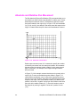
Absolute and Relative Pen Movement. . . . . . . . . . . . . . . . . . . . . . . . . . . . . . 17-25
The Picture Frame
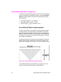
Defining the Image Area(PCL Picture Frame). . . . . . . . . . . . . . . . . . . . . . . . . 18-2
Automatically Adjusting Image Size to Fit the PCL Picture Frame . . . . . . . . . 18-3
Creating a Page Size-Independent Plot . . . . . . . . . . . . . . . . . . . . . . . . . 18-3
Typical HP-GL/2 PlotCommand Sequence . . . . . . . . . . . . . . . . . . . . . . . . . . . 18-5
Horizontal Picture Frame Size. . . . . . . . . . . . . . . . . . . . . . . . . . . . . . . . . . . . . 18-8
Example:. . . . . . . . . . . . . . . . . . . . . . . . . . . . . . . . . . . . . . . . . . . . . . . . . . 18-9
Vertical Picture Frame Size (Decipoints) . . . . . . . . . . . . . . . . . . . . . . . . . . . . . 18-9
Example:To specify a vertical picture frame size of 6.5 inches, send: . . . 18-9
Set Picture Frame Anchor Point . . . . . . . . . . . . . . . . . . . . . . . . . . . . . . . . . . 18-10
Example:. . . . . . . . . . . . . . . . . . . . . . . . . . . . . . . . . . . . . . . . . . . . . . . . . 18-10
HP-GL/2 Plot Horizontal Size . . . . . . . . . . . . . . . . . . . . . . . . . . . . . . . . . . . . 18-11
Example: . . . . . . . . . . . . . . . . . . . . . . . . . . . . . . . . . . . . . . . . . . . . . . . . 18-11
HP-GL/2 Plot Vertical Size . . . . . . . . . . . . . . . . . . . . . . . . . . . . . . . . . . . . . . 18-12
Example:. . . . . . . . . . . . . . . . . . . . . . . . . . . . . . . . . . . . . . . . . . . . . . . . . 18-12
Enter HP-GL/2 Mode. . . . . . . . . . . . . . . . . . . . . . . . . . . . . . . . . . . . . . . . . . . 18-13
Example: . . . . . . . . . . . . . . . . . . . . . . . . . . . . . . . . . . . . . . . . . . . . . . . . 18-13
Enter PCL Mode . . . . . . . . . . . . . . . . . . . . . . . . . . . . . . . . . . . . . . . . . . . . . . 18-14
Example: . . . . . . . . . . . . . . . . . . . . . . . . . . . . . . . . . . . . . . . . . . . . . . . . 18-14
Default Settings . . . . . . . . . . . . . . . . . . . . . . . . . . . . . . . . . . . . . . . . . . . . . . . 18-15
EN
Contents-9
The Configuration and Status Group
Establishing Default Conditions. . . . . . . . . . . . . . . . . . . . . . . . . . . . . . . . . . . . 19-3
The Scaling Points P1 and P2. . . . . . . . . . . . . . . . . . . . . . . . . . . . . . . . . . . . . 19-4
Using the Scale Command . . . . . . . . . . . . . . . . . . . . . . . . . . . . . . . . . . . . . . . 19-4
Using Scaling Effectively . . . . . . . . . . . . . . . . . . . . . . . . . . . . . . . . . . . . . . . . . 19-8
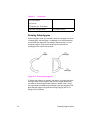
Enlarging or Reducing a Picture . . . . . . . . . . . . . . . . . . . . . . . . . . . . . . 19-8
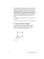
Drawing Equal-Size Pictures on a Page . . . . . . . . . . . . . . . . . . . . . . . . . 19-10
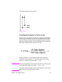
Creating Mirror-Images . . . . . . . . . . . . . . . . . . . . . . . . . . . . . . . . . . . . . 19-12
Adapting the HP-GL/2 Coordinate System to Match the PCL System 19-15
Windowing: Setting Up Soft-Clip Limits. . . . . . . . . . . . . . . . . . . . . . . . . . . . . 19-18
CO, Comment . . . . . . . . . . . . . . . . . . . . . . . . . . . . . . . . . . . . . . . . . . . . . . . . 19-19
DF, Default Values . . . . . . . . . . . . . . . . . . . . . . . . . . . . . . . . . . . . . . . . . . . . . 19-19
IN, Initialize . . . . . . . . . . . . . . . . . . . . . . . . . . . . . . . . . . . . . . . . . . . . . . . . . . 19-21
IP, Input P1 and P2 . . . . . . . . . . . . . . . . . . . . . . . . . . . . . . . . . . . . . . . . . . . . 19-23
IR, Input Relative P1 and P2 . . . . . . . . . . . . . . . . . . . . . . . . . . . . . . . . . . . . . 19-26
IW, Input Window . . . . . . . . . . . . . . . . . . . . . . . . . . . . . . . . . . . . . . . . . . . . . 19-29
PG, Advance Full Page . . . . . . . . . . . . . . . . . . . . . . . . . . . . . . . . . . . . . . . . . 19-33
RO, Rotate Coordinate System . . . . . . . . . . . . . . . . . . . . . . . . . . . . . . . . . . . 19-34
Angle of Rotation . . . . . . . . . . . . . . . . . . . . . . . . . . . . . . . . . . . . . . . . . . 19-34
RP, Replot . . . . . . . . . . . . . . . . . . . . . . . . . . . . . . . . . . . . . . . . . . . . . . . . . . . 19-39
SC, Scale . . . . . . . . . . . . . . . . . . . . . . . . . . . . . . . . . . . . . . . . . . . . . . . . . . . 19-40
For Scaling Types 0 and 1: . . . . . . . . . . . . . . . . . . . . . . . . . . . . . . . . . . 19-41
For Scaling Type 2: . . . . . . . . . . . . . . . . . . . . . . . . . . . . . . . . . . . . . . . . 19-44
The Vector Group
Drawing Lines . . . . . . . . . . . . . . . . . . . . . . . . . . . . . . . . . . . . . . . . . . . . . . . . . 20-2
Drawing Circles . . . . . . . . . . . . . . . . . . . . . . . . . . . . . . . . . . . . . . . . . . . . . . . . 20-4
Drawing Arcs . . . . . . . . . . . . . . . . . . . . . . . . . . . . . . . . . . . . . . . . . . . . . . . . . . 20-5
Angle of Rotation . . . . . . . . . . . . . . . . . . . . . . . . . . . . . . . . . . . . . . . . . . . 20-7
Drawing Bezier Curves . . . . . . . . . . . . . . . . . . . . . . . . . . . . . . . . . . . . . . . . . . 20-8
AA, Arc Absolute . . . . . . . . . . . . . . . . . . . . . . . . . . . . . . . . . . . . . . . . . . . . . . . 20-9
AR, Arc Relative . . . . . . . . . . . . . . . . . . . . . . . . . . . . . . . . . . . . . . . . . . . . . . 20-13
AT, Absolute Arc Three Point. . . . . . . . . . . . . . . . . . . . . . . . . . . . . . . . . . . . . 20-16
BR, Bezier Relative . . . . . . . . . . . . . . . . . . . . . . . . . . . . . . . . . . . . . . . . . . . . 20-19
BZ, Bezier Absolute. . . . . . . . . . . . . . . . . . . . . . . . . . . . . . . . . . . . . . . . . . . . 20-22
CI, Circle . . . . . . . . . . . . . . . . . . . . . . . . . . . . . . . . . . . . . . . . . . . . . . . . . . . . 20-25
PA, Plot Absolute. . . . . . . . . . . . . . . . . . . . . . . . . . . . . . . . . . . . . . . . . . . . . . 20-30
PD, Pen Down . . . . . . . . . . . . . . . . . . . . . . . . . . . . . . . . . . . . . . . . . . . . . . . . 20-31
PE, Polyline Encoded . . . . . . . . . . . . . . . . . . . . . . . . . . . . . . . . . . . . . . . . . . 20-34
Encoding PE Flag Values and X,Y Coordinates . . . . . . . . . . . . . . . . . . 20-37
Example: Using the PE Command . . . . . . . . . . . . . . . . . . . . . . . . . . . . . 20-41
PR, Plot Relative . . . . . . . . . . . . . . . . . . . . . . . . . . . . . . . . . . . . . . . . . . . . . . 20-44
U, Pen Up . . . . . . . . . . . . . . . . . . . . . . . . . . . . . . . . . . . . . . . . . . . . . . . . . . . 20-46
RT, Relative Arc Three Point . . . . . . . . . . . . . . . . . . . . . . . . . . . . . . . . . . . . . 20-48
Contents-10
EN
The Polygon Group
Using the Polygon Buffer. . . . . . . . . . . . . . . . . . . . . . . . . . . . . . . . . . . . . . . . . 21-2
Drawing Rectangles . . . . . . . . . . . . . . . . . . . . . . . . . . . . . . . . . . . . . . . . . . . . 21-3
Drawing Wedges . . . . . . . . . . . . . . . . . . . . . . . . . . . . . . . . . . . . . . . . . . . . . . . 21-6
Drawing Polygons . . . . . . . . . . . . . . . . . . . . . . . . . . . . . . . . . . . . . . . . . . . . . 21-10
Drawing Subpolygons . . . . . . . . . . . . . . . . . . . . . . . . . . . . . . . . . . . . . . 21-11
Filling Polygons
. . . . . . . . . . . . . . . . . . . . . . . . . . . . . . . . . . . . . . . . . 21-12
Drawing Circles in Polygon Mode . . . . . . . . . . . . . . . . . . . . . . . . . . . . 21-14
`Approximating Polygon Buffer Use . . . . . . . . . . . . . . . . . . . . . . . . . . . . 21-14
Counting the Points in a Polygon . . . . . . . . . . . . . . . . . . . . . . . . . . . . . . 21-15
Counting the Points in a Circle or Arc . . . . . . . . . . . . . . . . . . . . . . . . . . 21-16
EA, Edge Rectangle Absolute . . . . . . . . . . . . . . . . . . . . . . . . . . . . . . . . . . . . 21-17
EP, Edge Polygon . . . . . . . . . . . . . . . . . . . . . . . . . . . . . . . . . . . . . . . . . . . . . 21-21
ER, Edge Rectangle Relative . . . . . . . . . . . . . . . . . . . . . . . . . . . . . . . . . . . . 21-23
EW, Edge Wedge . . . . . . . . . . . . . . . . . . . . . . . . . . . . . . . . . . . . . . . . . . . . . 21-27
FP, Fill Polygon . . . . . . . . . . . . . . . . . . . . . . . . . . . . . . . . . . . . . . . . . . . . . . . 21-31
PM, Polygon Mode Command. . . . . . . . . . . . . . . . . . . . . . . . . . . . . . . . . . . . 21-34
(PM0) or (PM) . . . . . . . . . . . . . . . . . . . . . . . . . . . . . . . . . . . . . . . . . . . . . 21-34
(PM1) . . . . . . . . . . . . . . . . . . . . . . . . . . . . . . . . . . . . . . . . . . . . . . . . . . . 21-36
(PM2) . . . . . . . . . . . . . . . . . . . . . . . . . . . . . . . . . . . . . . . . . . . . . . . . . . . 21-37
RA, Fill Rectangle Absolute. . . . . . . . . . . . . . . . . . . . . . . . . . . . . . . . . . . . . . 21-39
RR, Fill Rectangle Relative . . . . . . . . . . . . . . . . . . . . . . . . . . . . . . . . . . . . . . 21-42
WG, Fill Wedge . . . . . . . . . . . . . . . . . . . . . . . . . . . . . . . . . . . . . . . . . . . . . 21-45
The Line and Fill Attributes Group
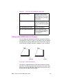
Using Line Attributes and Types . . . . . . . . . . . . . . . . . . . . . . . . . . . . . . . . . . . 22-2
Using Fill Types . . . . . . . . . . . . . . . . . . . . . . . . . . . . . . . . . . . . . . . . . . . . . . . . 22-4
Selecting a “Pen” and Changing Line Width . . . . . . . . . . . . . . . . . . . . . . . . . . 22-5
AC, Anchor Corner . . . . . . . . . . . . . . . . . . . . . . . . . . . . . . . . . . . . . . . . . . . . . 22-6
FT, Fill Type . . . . . . . . . . . . . . . . . . . . . . . . . . . . . . . . . . . . . . . . . . . . . . . . . . . 22-9
LA, Line Attributes . . . . . . . . . . . . . . . . . . . . . . . . . . . . . . . . . . . . . . . . . . . . . 22-15
Line Ends . . . . . . . . . . . . . . . . . . . . . . . . . . . . . . . . . . . . . . . . . . . . . . . . 22-17
Line Joins . . . . . . . . . . . . . . . . . . . . . . . . . . . . . . . . . . . . . . . . . . . . . . . . 22-17
Miter Limit . . . . . . . . . . . . . . . . . . . . . . . . . . . . . . . . . . . . . . . . . . . . . . . 22-19
LT, Line Type . . . . . . . . . . . . . . . . . . . . . . . . . . . . . . . . . . . . . . . . . . . . . . . . . 22-22
PW, Pen Width . . . . . . . . . . . . . . . . . . . . . . . . . . . . . . . . . . . . . . . . . . . . . . . 22-29
RF, Raster Fill Definition . . . . . . . . . . . . . . . . . . . . . . . . . . . . . . . . . . . . . . . . 22-32
SM, Symbol Mode . . . . . . . . . . . . . . . . . . . . . . . . . . . . . . . . . . . . . . . . . . . . . 22-35
SP, Select Pen . . . . . . . . . . . . . . . . . . . . . . . . . . . . . . . . . . . . . . . . . . . . . . . . 22-38
SV, Screened Vectors . . . . . . . . . . . . . . . . . . . . . . . . . . . . . . . . . . . . . . . . . . 22-39
TR, Transparency Mode . . . . . . . . . . . . . . . . . . . . . . . . . . . . . . . . . . . . . . . . 22-42
UL, User-Defined Line Type . . . . . . . . . . . . . . . . . . . . . . . . . . . . . . . . . . . . . 22-44
WU, Pen Width Unit Selection . . . . . . . . . . . . . . . . . . . . . . . . . . . . . . . . . . . . 22-46
EN
Contents-11
The Character Group
Printing Labels . . . . . . . . . . . . . . . . . . . . . . . . . . . . . . . . . . . . . . . . . . . . . . . . 23-3
Moving to the Carriage Return Point . . . . . . . . . . . . . . . . . . . . . . . . . . . . 23-5
Control Codes . . . . . . . . . . . . . . . . . . . . . . . . . . . . . . . . . . . . . . . . . . . . . 23-6
Default Label Conditions . . . . . . . . . . . . . . . . . . . . . . . . . . . . . . . . . . . . . . . . . 23-7
Enhancing Labels . . . . . . . . . . . . . . . . . . . . . . . . . . . . . . . . . . . . . . . . . . . . . . 23-8
Character Size and Slant
. . . . . . . . . . . . . . . . . . . . . . . . . . . . . . . . 23-8
Character Spaces and Text Lines
. . . . . . . . . . . . . . . . . . . . . . . . . . . . 23-8
Label Orientation and Placement
. . . . . . . . . . . . . . . . . . . . . . . . . . 23-9
Terminating Labels . . . . . . . . . . . . . . . . . . . . . . . . . . . . . . . . . . . . . . . . . 23-11
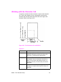
Working with the Character Cell . . . . . . . . . . . . . . . . . . . . . . . . . . . . . . . . . . 23-12
Using Fonts . . . . . . . . . . . . . . . . . . . . . . . . . . . . . . . . . . . . . . . . . . . . . . . . . . 23-15
Printing with Fixed-Spaced and Proportional Fonts
. . . . . . . . . . . . . 23-15
Designating and Selecting Fonts. . . . . . . . . . . . . . . . . . . . . . . . . . . . . . . . . . 23-17
Standard and Alternate Fonts . . . . . . . . . . . . . . . . . . . . . . . . . . . . . . . . 23-17
AD, Alternate Font Definition . . . . . . . . . . . . . . . . . . . . . . . . . . . . . . . . . . . . . 23-18
CF, Character Fill Mode. . . . . . . . . . . . . . . . . . . . . . . . . . . . . . . . . . . . . . . . . 23-20
CP, Character Plot . . . . . . . . . . . . . . . . . . . . . . . . . . . . . . . . . . . . . . . . . . . . . 23-24
DI, Absolute Direction . . . . . . . . . . . . . . . . . . . . . . . . . . . . . . . . . . . . . . . . . . 23-29
DR, Relative Direction . . . . . . . . . . . . . . . . . . . . . . . . . . . . . . . . . . . . . . . . . . 23-37
Example:Using the DR Command . . . . . . . . . . . . . . . . . . . . . . . . . . . . 23-41
DT, Define Label Terminator . . . . . . . . . . . . . . . . . . . . . . . . . . . . . . . . . . . . . 23-44
DV, Define Variable Text Path . . . . . . . . . . . . . . . . . . . . . . . . . . . . . . . . . . . . 23-46
Example:Using theDV Command . . . . . . . . . . . . . . . . . . . . . . . . . . . . . 23-49
ES, Extra Space . . . . . . . . . . . . . . . . . . . . . . . . . . . . . . . . . . . . . . . . . . . . . . 23-51
FI, Select Primary Font . . . . . . . . . . . . . . . . . . . . . . . . . . . . . . . . . . . . . . . . . 23-54
Example:Using the FI Command . . . . . . . . . . . . . . . . . . . . . . . . . . . . . . 23-54
FN, Select Secondary Font . . . . . . . . . . . . . . . . . . . . . . . . . . . . . . . . . . . . . . 23-56
Example:Using the FN Command . . . . . . . . . . . . . . . . . . . . . . . . . . . . . 23-57
LB, Label . . . . . . . . . . . . . . . . . . . . . . . . . . . . . . . . . . . . . . . . . . . . . . . . . . . . 23-59
LO, Label Origin . . . . . . . . . . . . . . . . . . . . . . . . . . . . . . . . . . . . . . . . . . . . . . 23-62
SA, Select Alternate Font . . . . . . . . . . . . . . . . . . . . . . . . . . . . . . . . . . . . . . . 23-66
SB, Scalable or Bitmap Fonts . . . . . . . . . . . . . . . . . . . . . . . . . . . . . . . . . . . . 23-67
SD, Standard Font Definition . . . . . . . . . . . . . . . . . . . . . . . . . . . . . . . . . . . . . 23-68
Kind 1: Symbol Set . . . . . . . . . . . . . . . . . . . . . . . . . . . . . . . . . . . . . . . . . 23-69
Kind 2: Font Spacing . . . . . . . . . . . . . . . . . . . . . . . . . . . . . . . . . . . . . . 23-70
Kind 3: Pitch . . . . . . . . . . . . . . . . . . . . . . . . . . . . . . . . . . . . . . . . . . . . . 23-70
Kind 4: Height . . . . . . . . . . . . . . . . . . . . . . . . . . . . . . . . . . . . . . . . . . . 23-71
Kind 5: Posture . . . . . . . . . . . . . . . . . . . . . . . . . . . . . . . . . . . . . . . . . . . . 23-71
Kind 6: Stroke Weight . . . . . . . . . . . . . . . . . . . . . . . . . . . . . . . . . . . . . . . 23-71
Kind 7: Typeface . . . . . . . . . . . . . . . . . . . . . . . . . . . . . . . . . . . . . . . . . 23-72
Example:Using the SD Command . . . . . . . . . . . . . . . . . . . . . . . . . . . . . 23-73
SI, Absolute Character Size . . . . . . . . . . . . . . . . . . . . . . . . . . . . . . . . . . . . . 23-74
Example:Using the SI Command . . . . . . . . . . . . . . . . . . . . . . . . . . . . . . 23-75
SL, Character Slant . . . . . . . . . . . . . . . . . . . . . . . . . . . . . . . . . . . . . . . . . . . . 23-78
Example:Using the SL Command . . . . . . . . . . . . . . . . . . . . . . . . . . . . . 23-79
Contents-12
EN
SR, Relative Character Size . . . . . . . . . . . . . . . . . . . . . . . . . . . . . . . . . . . . .
Example:Using the SR Command . . . . . . . . . . . . . . . . . . . . . . . . . . . . .
SS, Select Standard Font . . . . . . . . . . . . . . . . . . . . . . . . . . . . . . . . . . . . . . .
TD, Transparent Data . . . . . . . . . . . . . . . . . . . . . . . . . . . . . . . . . . . . . . . . . .
23-81
23-83
23-85
23-86
Programming Hints
PCL Command Parsing. . . . . . . . . . . . . . . . . . . . . . . . . . . . . . . . . . . . . . . . . . 24-2
Job Control . . . . . . . . . . . . . . . . . . . . . . . . . . . . . . . . . . . . . . . . . . . . . . . . . . . 24-3
Printer Reset. . . . . . . . . . . . . . . . . . . . . . . . . . . . . . . . . . . . . . . . . . . . . . . 24-3
PCL Page Control 1 . . . . . . . . . . . . . . . . . . . . . . . . . . . . . . . . . . . . . . . . . . . . 24-4
Paper Source . . . . . . . . . . . . . . . . . . . . . . . . . . . . . . . . . . . . . . . . . . . . . 24-4
Page Size . . . . . . . . . . . . . . . . . . . . . . . . . . . . . . . . . . . . . . . . . . . . . . . 24-4
Text Area/Margins
. . . . . . . . . . . . . . . . . . . . . . . . . . . . . . . . . . . . . . . . 24-4
HMI . . . . . . . . . . . . . . . . . . . . . . . . . . . . . . . . . . . . . . . . . . . . . . . . . . . . 24-4
PCL Cursor Positioning . . . . . . . . . . . . . . . . . . . . . . . . . . . . . . . . . . . . . . . . . . 24-5
Fonts . . . . . . . . . . . . . . . . . . . . . . . . . . . . . . . . . . . . . . . . . . . . . . . . . . . . . . . . 24-5
PCL Raster Graphics . . . . . . . . . . . . . . . . . . . . . . . . . . . . . . . . . . . . . . . . . . . 24-7
Macros. . . . . . . . . . . . . . . . . . . . . . . . . . . . . . . . . . . . . . . . . . . . . . . . . . . . . . . 24-8
HP-GL/2 Vector Graphics . . . . . . . . . . . . . . . . . . . . . . . . . . . . . . . . . . . . . . . . 24-9
Performance . . . . . . . . . . . . . . . . . . . . . . . . . . . . . . . . . . . . . . . . . . . . . . . . . 24-10
PCL Commands . . . . . . . . . . . . . . . . . . . . . . . . . . . . . . . . . . . . . . . . . . . 24-10
Print Data . . . . . . . . . . . . . . . . . . . . . . . . . . . . . . . . . . . . . . . . . . . . . . . 24-10
Print Overrun . . . . . . . . . . . . . . . . . . . . . . . . . . . . . . . . . . . . . . . . . . . . . 24-10
Page Protection . . . . . . . . . . . . . . . . . . . . . . . . . . . . . . . . . . . . . . . . . . . 24-10
I/O . . . . . . . . . . . . . . . . . . . . . . . . . . . . . . . . . . . . . . . . . . . . . . . . . . . . . 24-11
Troubleshooting Commands . . . . . . . . . . . . . . . . . . . . . . . . . . . . . . . . . . . . . 24-12
End-of-Line Wrap . . . . . . . . . . . . . . . . . . . . . . . . . . . . . . . . . . . . . . . . . . 24-12
Example . . . . . . . . . . . . . . . . . . . . . . . . . . . . . . . . . . . . . . . . . . . . . . . . . 24-12
Display Functions Mode
. . . . . . . . . . . . . . . . . . . . . . . . . . . . . . . . . . 24-12
Example . . . . . . . . . . . . . . . . . . . . . . . . . . . . . . . . . . . . . . . . . . . . . . . . . 24-13
Auto Continue Mode . . . . . . . . . . . . . . . . . . . . . . . . . . . . . . . . . . . . . . 24-14
Common Errors . . . . . . . . . . . . . . . . . . . . . . . . . . . . . . . . . . . . . . . . . . . . . . . 24-15
20 ERROR . . . . . . . . . . . . . . . . . . . . . . . . . . . . . . . . . . . . . . . . . . . . . . 24-15
21 ERROR . . . . . . . . . . . . . . . . . . . . . . . . . . . . . . . . . . . . . . . . . . . . . . 24-15
22 ERROR . . . . . . . . . . . . . . . . . . . . . . . . . . . . . . . . . . . . . . . . . . . . . . 24-15
40 ERROR . . . . . . . . . . . . . . . . . . . . . . . . . . . . . . . . . . . . . . . . . . . . . . . 24-15
Customer Support
Help From Your Organization . . . . . . . . . . . . . . . . . . . . . .Customer Support-1
Help From Your Dealer . . . . . . . . . . . . . . . . . . . . . . . . . . .Customer Support-1
Help from HP . . . . . . . . . . . . . . . . . . . . . . . . . . . . . . . . . .Customer Support-1
Index
EN
Contents-13
Contents-14
EN
1
Introduction to
HP PCL
PCL PRINTER LANGUAGE HISTORY
Hewlett-Packard created the PCL printer language (simply
referred to as “PCL” elsewhere in this manual) to provide an
economical and efficient way for application programs to control
a range of printer features across a number of printing devices.
HP has evolved both the definition and implementations of PCL
to provide the optimal price and performance balance. PCL 5
represents a new breakthrough in price/performance leadership.
Its features were selected in direct response to customer
requests. HP will continue to lead enhancements to the PCL
printer language to deliver powerful technology advances.
PCL commands are compact escape sequence codes that are
embedded in the print job data stream. This approach minimizes
both data transmission and command decoding overhead.
HP PCL formatters and fonts are designed to quickly translate
application output into high-quality, device-specific, raster print
images.
PCL printer language commonality from HP printer to HP printer
helps to minimize printer support problems and protect HP
printer customer investment in applications and printer driver
software.
EN
PCL PRINTER LANGUAGE HISTORY 1-1
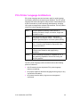
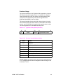
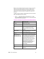
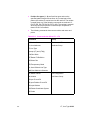
PCL Printer Language Architecture
PCL printer language structure has been useful to guide language
functionality growth and command syntax definition. The PCL printer
language has evolved through five major levels of functionality driven
by the combination of printer technology developments, changing
user needs, and application software improvements. The five phases
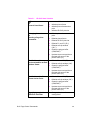
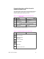
of the PCL printer language evolution are:
PCL 1
Print and Space functionality is the base set of
functions provided for simple, convenient, single-user
workstation output.
PCL 2
EDP (Electronic Data Processing) /Transaction
functionality is a superset of PCL 1. Functions were
added for general purpose, multi-user system printing.
PCL 3
Office Word Processing functionality is a superset of
PCL 2. Functions were added for high-quality, office
document production.
PCL 4
Page Formatting functionality is a superset of PCL 3.
Functions were added for new page printing
capabilities.
PCL 5
Office Publishing functionality is a superset of PCL 4.
New publishing capabilities include font scaling and
HP-GL/2 graphics.
The PCL printer language model succeeds because the following
points are observed:
z
All HP LaserJet printers implement PCL printer language
features consistently.
z
HP printers implement the above language feature groups in very
cost-effective formatters.
z
HP printers have the ability to ignore most unsupported
commands.
1-2 Introduction to HP PCL
EN
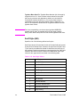
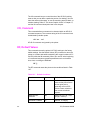
What are Printer Commands?
PCL printer commands provide access to printer features. There are
four general types of HP printer language commands:
z
control codes
z
PCL commands
z
HP-GL/2 commands
z
PJL commands
Control Codes
A control code is a character that initiates a printer function, for
example Carriage Return (CR), Line Feed (LF), Form Feed (FF), etc.
PCL Commands
PCL commands provide access to the printer’s PCL control structure.
The PCL structure controls all of the printer’s features except those
used for vector graphics, which are controlled by the HP-GL/2
commands.
PCL printer commands consist of two or more characters. The first
character is always the ASCII escape character, identified by the ?
symbol. ? is a special control code which identifies the subsequent
string of characters as a printer command. As the printer monitors
incoming data from a computer, it “looks” for this character. When this
character appears, the printer reads it and its associated characters
as a command to perform and not as data to print.
Note
PCL printer commands (other than single-character control codes)
are also referred to as escape sequences. The terms printer
command and escape sequence are used interchangeably
throughout this manual.
Once a PCL command sets a parameter, that parameter remains set
until that PCL command is repeated with a new value, or the printer is
reset to its user default environment. For example, if you send the
printer a command to set line spacing to 3 lines/inch, each page
prints 3 lines/inch until the printer receives a different Line Spacing
command, or the printer is reset.
EN
What are Printer Commands? 1-3
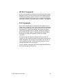
HP-GL/2 Commands
HP-GL/2, vector graphic commands are two letter mnemonic codes
designed to remind you of the function name (such as IN for Initialize).
Following the two letter mnemonic may be one or more parameters,
which identify details of how to process the command. For additional
information on HP-GL/2 commands, refer to Chapters 17 through 23.
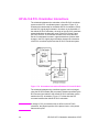
PJL Commands
PJL (Printer Job Language) commands provide a different type of
printer control. Unlike PCL and HP-GL/2, which control the placement
of dots on the printed page, PJL supplies job-level control. One of the
main features PJL offers is the ability to switch printer languages
(personalities) between jobs. For example, applications supporting
PJL can print one job using PCL, and then print the next job using
PostScript or another printer language, without any operator
intervention.
PJL also provides two-way communications with the printer. For
example, PJL can request information from the printer such as printer
model, configuration, printer status, and job status. PJL also can be
used to change the printer’s control panel settings and modify the
message displayed on the control panel.
The PJL language is designed to be used by application developers
and technical support personnel only.
1-4 Introduction to HP PCL
EN
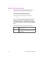
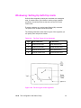
Syntax of Escape Sequences
There are two forms of PCL escape sequences: two-character
escape sequences and parameterized escape sequences.
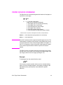
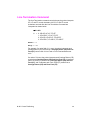
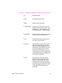
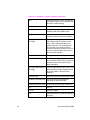
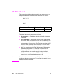
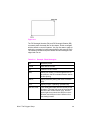
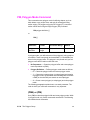
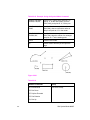
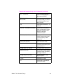
Two-Character Escape Sequences
Two-character escape sequences have the following form:
?X
where “X” is a character that defines the operation to be performed.
“X” may be any character from the ASCII table within the range
48-126 decimal (“0” through “~” - see Appendix A). For a list of the
two-character escape sequences supported by the printer, refer to the
“PCL Feature Support Matrix” in Chapter 1 of the PCL 5 Comparison
Guide.
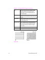
Following are examples of two-character escape sequences:
EN
?E
a two-character escape sequence used for
resetting the printer.
?9
a two-character escape sequence used for
resetting the left and right margins to the printer’s
default settings.
Syntax of Escape Sequences 1-5
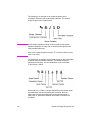
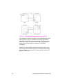
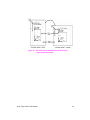
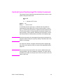
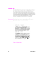
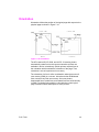
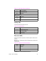
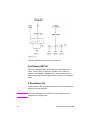
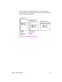
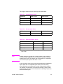
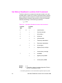
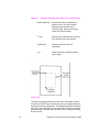
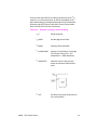
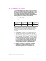
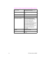
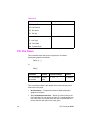
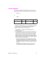
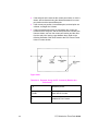
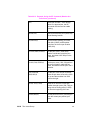
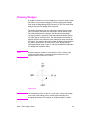
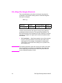
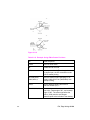
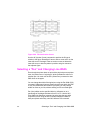
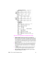
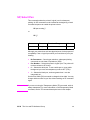
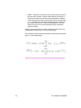
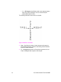
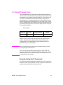
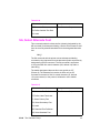
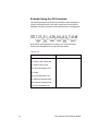
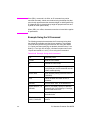
Parameterized Escape Sequences
Parameterized escape sequences have the following form:
? X y z1 # z2 # z3 ... # Zn[data]
where y, #, zi (z1, z2, z3...) and [data] may be optional, depending on
the command.
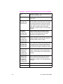
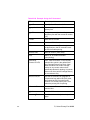
X
Parameterized Character - A character from the
ASCII table within the range 33-47 decimal
(“!” through “/”) indicating that the escape sequence is
parameterized.
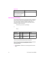
y
Group Character - A character from the ASCII table
within the range 96-126 decimal (“ ‘ ” through “ ~ ”) that
specifies the group type of control being performed.
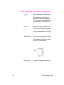
#
Value Field - A group of characters specifying a
numeric value. The numeric value is represented as an
ASCII string of characters within the range 48-57
decimal (“0” through “9”) that may be preceded by a “+”
or “—” sign and may contain a fractional portion
indicated by the digits after a decimal point (“ . ”).
Numeric value fields are within the range -32767 to
65535. If an escape sequence requires a value field
and a value is not specified, a value of zero is
assumed.
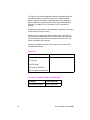
zi
Parameter Character - Any character from the ASCII
table within the range 96-126 decimal (“ ‘ ” through
“ ~ ”). This character specifies the parameter to which
the previous value field applies. This character is used
when combining escape sequences.
Zn
Termination Character - Any character from the
ASCII table within the range 64-94 decimal
(“ @ ” through “ ^ ”). This character specifies the
parameter to which the previous value field applies.
This character terminates the escape sequence.
[data]
Binary Data is eight-bit data (for example, graphics
data, downloaded fonts, etc.). The number of bytes of
binary data is specified by the value field of the escape
sequence. Binary data immediately follows the
terminating character of the escape sequence.
1-6 Introduction to HP PCL
EN
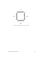
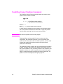
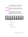
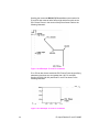
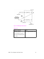
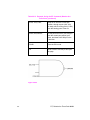
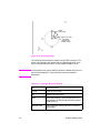
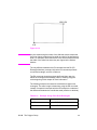
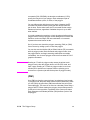
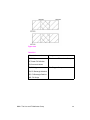
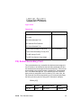
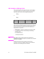
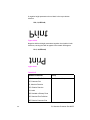
The following is an example of an escape sequence with a
termination character and no parameter character. This escape
sequence performs a single function.
Notes
Some escape sequences shown in this manual contain spaces
between characters for clarity. Do not include these spaces when
using escape sequences.
Also, in the escape sequence a script “l” is used to indicate a lower
case “l” for clarity.
The following is an example of an escape sequence with a parameter
character and a termination character. This escape sequence
performs two functions. It is the combination of two commands
(?&l1O and ?&l2A):
Notice that the “?”and the “&l”are dropped from the second printer
command when the two commands are combined. Also, the
upper-case “O” that terminated the first command becomes a
lower-case “o” parameter character when these commands are
combined.
EN
Syntax of Escape Sequences 1-7
Use these three rules to combine and shorten printer commands:
1
The first two characters after “?” (the parameterized and group
character) must be the same in all of the commands to be
combined. In the example above, these are “&” and “l”.
2
All alphabetic characters within the combined printer command
are lower-case, except the final letter which is always upper-case.
In the combined example above, “O” becomes “o”. The final
character in the printer command must always be upper-case to
let the printer know that the command is complete.
3
The printer commands are performed in the order that they are
combined (from left to right). Be sure to combine commands in
the order that they are to be performed.
1-8 Introduction to HP PCL
EN
2
The Page
Introduction
This chapter describes the PCL coordinate system. It defines
the logical page and the printable area; it introduces the HP-GL/2
(vector graphics) picture frame, and identifies the boundaries of each.
EN
Introduction 2-1
Logical Page
The PCL logical page (also referred to as the PCL addressable area)
defines the area in which the PCL cursor can be positioned. Although
the printer does not actually have a cursor (like the blinking underline
character used on most computer terminals), the cursor position
refers to the Currently Active Position of the cursor (also referred to as
the CAP). The location of the “cursor” is the position on the logical
page where the next character will be positioned. The cursor can be
moved to different points on the logical page using the cursor
positioning commands (see Chapter 6, Cursor Positioning). The PCL
cursor cannot be moved outside of the logical page bounds.
The size of the logical page for the media (paper, transparencies,
labels, etc.) is defined in Table 2-1 and Table 2-2.
2-2 The Page
EN
Printed Dots
The high quality output achieved by HP LaserJet printers is due in
part to the ability to lay down a fine grid of “dots” on the page. The
density of this grid is referred to as the printer’s resolution. From
the first HP LaserJet (the “LaserJet Classic”) until recently, all
HP LaserJet family printers printed at a resolution of 300
dots-per-inch. In a one inch square, the printer could print a dot
anywhere in a grid of up to 300 dots horizontally by 300 dots
vertically, for a total of 90,000 possible dot locations per square inch
(300 × 300 = 90,000).
The LaserJet 4 printer is capable of printing at either 300 or 600 dpi
resolution. At 600 dots-per-inch, it becomes possible to print up to
360,000 dots per square inch (600 x 600 = 360,000). Print resolution
of LaserJet 4 is selectable and can be specified either from the
printer’s control panel or programmed through PJL commands.
Figure 2-1 300 vs 600 DPI Dot Sizes
Note
Refer to Appendix E of the PCL 5 Comparison Guide or the printer
User’s Manual to determine the default print resolution for a specific
HP LaserJet printer.
The printer’s physical dot size has no direct bearing on the size of
“PCL Units” used in cursor movements. PCL Units were previously
referred to as “PCL dots”, but should not be confused with the
printer’s physically printed dots. The size of PCL Units can also
be specified (see the Unit of Measure Command in Chapter 4 for
more information).
EN
Printed Dots 2-3
PCL Coordinate System
The PCL coordinate system is defined as shown in Figure 2-2.
Figure 2-2 X,Y PCL Coordinates
The point (0,0) is at the intersection of the left edge of the logical page
and the current top margin position.
Note
2-4 The Page
Since the point (0,0) is always at the intersection of the left edge of
the logical page and the current top margin position, it moves if the
top margin is changed, and rotates around the page if the orientation
is changed.
EN
Units of the PCL Coordinate System
The units of the X-axis of the PCL coordinate system may be PCL
Units, decipoints, or columns. The units of the Y-axis may be PCL
Units, decipoints, or rows.
PCL Units
These are user-definable units of measure which are used in PCL
commands affecting various PCL cursor moves. The number of
units-per-inch used in PCL cursor moves is determined by the current
setting of the Unit of Measure command (see “Unit of Measure
Command” in Chapter 4).
Note
PCL Units were formerly referred to as “PCL Dots”. They were
renamed “PCL Units” to prevent confusion with the printer’s physically
printed “dots”, which are determined by the printer’s resolution.
Decipoints
In PCL terminology, a decipoint is 1/720 inch or one-tenth of a
PCL point (a PCL point is 1/72 inch as opposed to a typographic point
which is 1/72 inch).
Columns & Rows
The width of a column is defined by the current horizontal motion
index (HMI). The distance between rows is defined by the current
vertical motion index (VMI), or lines-per-inch (lpi). HMI, VMI and
lpi are described in Chapter 5, Page Control Commands.
Printer Internal Units
Internally, the printer uses a different unit of measure. It maps PCL
Units, decipoints, and columns and rows to this unit of measure. This
internal unit is 1/7200 inch. All positioning is kept in internal units and
rounded to physical dot positions when data is printed.
EN
Units of the PCL Coordinate System 2-5
HP-GL/2 Picture Frame
In addition to text and raster graphics, HP-GL/2 vector graphics
can be placed on the PCL logical page. HP-GL/2 vector graphics
are incorporated using the concept of the HP-GL/2 picture frame
(see Figure 2-3). Within this picture frame, HP-GL/2 uses its own
coordinate system and units of measure. The HP-GL/2 coordinate
system and units are described in detail in Chapter 17, An
Introduction to HP-GL/2 Vector Graphics, and Chapter 18, The
Picture Frame.
Note
If no HP-GL/2 picture frame size is specified (using the commands
described in Chapter 18), then the default HP-GL/2 picture frame is
used. The default HP-GL/2 picture frame is the current top and
bottom margins and the left and right edges of the logical page. The
HP-GL/2 picture frame rotates with the PCL page orientation, but is
not affected by the PCL print direction.
Figure 2-3 PCL Logical Page with HP-GL/2 Picture Frame
2-6 The Page
EN
Printable Area
The printable area is the area of the physical page in which the
printer is able to place a dot. The physical page refers to the size of
the media (letter, legal, etc.) installed in the printer.
The relationship between physical page, logical page, default picture
frame, and printable area is defined in Table 2-1 and Table 2-2.
Table 2-1
Portrait Logical Page & Printable Area Boundaries
DIMENSIONS
(at 300 DPI - double for 600 DPI)
PAPER SIZE
A
B
C
D
E
F
G
H
LETTER
2550
3300
2400
3300
75
0
50
150
Legal List 1
2550
4200
2400
4200
75
0
50
150
LEDGER
3300
5100
3150
5100
75
0
50
150
EXECUTIVE
2175
3150
2025
3150
75
0
50
150
A4
2480
3507
2338
3507
71
0
50
150
A3
3507
4960
3365
4960
71
0
50
150
COM-10
1237
2850
1087
2850
75
0
50
150
MONARCH
1162
2250
1012
2250
75
0
50
150
C5
1913
2704
1771
2704
71
0
50
150
B5
2078
2952
1936
2952
71
0
50
150
DL
1299
2598
1157
2598
71
0
50
150
EN
Printable Area 2-7
Table 2-2
Landscape Logical Page & Printable Area Boundaries
DIMENSIONS
(at 300 DPI - double for 600 DPI)
PAPER SIZE
A
B
C
D
E
F
G
H
LETTER
3300
2550
3180
2550
60
0
50
150
Legal List 1
4200
2550
4080
2550
60
0
50
150
LEDGER
5100
3300
4980
3300
60
0
50
150
EXECUTIVE
3150
2175
3030
2175
60
0
50
150
A4
3507
2480
3389
2480
59
0
50
150
A3
4960
3507
4842
3507
59
0
50
150
COM-10
2850
1237
2730
1237
60
0
50
150
MONARCH
2250
1162
2130
1162
60
0
50
150
C5
2704
1913
2586
1913
59
0
50
150
B5
2952
2078
2834
2078
59
0
50
150
DL
2598
1299
2480
1299
59
0
50
150
2-8 The Page
EN
The HP LaserJet printers perform pixel-level clipping. When printing
characters or graphics, if any portion of the character cell or graphic is
outside the printable area, only that portion outside the printable area
is clipped (see Figure 2-4).
Figure 2-4 Printable Area Character Cell Positioning
Notes
Pixel level clipping can also occur at the logical page for PCL when
the page is positioned using the Left Registration command.
Pixel level clipping also occurs at the picture frame for HP-GL/2.
Characters are clipped if they fall across a margin (left, right, top, and
bottom). Refer to “Text Area” in Chapter 5 for additional information.
EN
Printable Area 2-9
2-10 The Page
EN
3
The Print
Environment
Introduction
The group of all of the printer’s current feature settings,
collectively, is referred to as the print environment. The printer
maintains four print environments: the Factory Default
Environment, the User Default Environment, the Modified
Print Environment and the Overlay Environment. This chapter
describes the Factory Default Environment, the User Default
Environment, and the Modified Print Environment (the Overlay
Environment is described in Chapter 12, Macros).
Default settings refer to the settings programmed into the printer
at the factory or settings selected using the control panel. The
term “default” simply refers to the settings the printer uses unless
printer commands select other settings.
Each time a job is printed, some of the printer’s feature settings
may be changed from their default values to produce the desired
printed output for that job. After the job prints, the job-specific
feature settings are longer be required, since the next job is likely
to have different output requirements. The next job should clear
all previous job settings by performing a reset. This allows a job
to start with the default settings as a known base set, and vary
only those settings that are needed. Starting with the default
environment at the beginning of each print job eliminates the
need to set every feature each time a job is run.
Note
EN
The print environment features presented in this chapter are for a
variety of HP LaserJet printers. Not all of the features are applicable
to every printer. To identify variations and default settings for specific
printers, refer to Chapter 3 of the PCL 5 Comparison Guide.
Introduction 3-1
Factory Default Environment
A factory default is a feature setting programmed into the printer at
the factory. The group of all of the printer’s feature settings set to their
factory settings is referred to as the Factory Default Environment.
These features are described in this manual. Since the HP-GL/2
features are used for HP-GL/2 operation only, the print environment
features are separated, for convenience, into two lists or contexts:
PCL and HP-GL/2. Table 3-1 lists typical PCL print environment
features, and Table 3-2 lists typical HP-GL/2 print environment
features.
Note
he factory default settings for the printer features are not shown here,
since they differ depending on the printer model. To identify variations
and default settings for specific printers, refer to Chapter 3 of the
PCL 5 Comparison Guide.
Table 3-1
Factory Default Print Environment Features –
PCL Context
JOB CONTROL
FONTS1
Number of Copies2
Symbol Set23
Duplex2
Spacing
Binding2, 3
Pitch4
Registration
Height5
Tray2
Style
Manual Feed2
Stroke Weight
User-defined Units
Typeface
Underlining Mode
1. The font characteristics are determined by the default font. The default font can
be the factory default font or the user-selected default font from the printer’s
control panel or from a font cartridge containing a default font.
2. User default values may be selected by the user from the printer’s control panel
for these items.
3. Selectable from the printer control panel if duplex is selected.
4. Selectable from the printer’s control panel if a fixed-space scalable font has been
selected as the user default.
5. Selectable from the printer’s control panel if a proportional scalable font has been
selected as the user default.
3-2 The Print Environment
EN
Table 3-1
Factory Default Print Environment Features –
PCL Context (continued)
PAGE CONTROL
FONT MANAGEMENT
Print Direction
Font ID
Orientation2
Character Code
Page
Size2
Symbol Set ID
Paper Source
RASTER GRAPHICS
Vertical Motion Index2
Horizontal Motion
Index2
Left Graphics Margin
Resolution
Top Margin
Compression Mode
Text Length
Raster Height
Left Margin
Raster Width
Right Margin
Raster Graphics Presentation
Mode
Perforation Skip
PICTURE FRAME
Line Termination
Picture Frame Width
PRINT MODEL
Picture Frame Height
Current Pattern
Picture Frame Anchor Point
Source Transparency Mode
HP-GL/2 plot Horizontal Size
Pattern Transparency Mode
HP-GL/2 Plot Vertical Size
Pattern Reference Point
MACRO
Pattern Rotation
Macro ID
1. The font characteristics are determined by the default font. The default font can
be the factory default font or the user-selected default font from the printer’s
control panel or from a font cartridge containing a default font.
2. User default values may be selected by the user from the printer’s control panel
for these items.
3. Selectable from the printer control panel if duplex is selected.
4. Selectable from the printer’s control panel if a fixed-space scalable font has been
selected as the user default.
5. Selectable from the printer’s control panel if a proportional scalable font has been
selected as the user default.
EN
Factory Default Environment 3-3
Table 3-1
Factory Default Print Environment Features –
PCL Context (continued)
RECTANGULAR AREA FILL
TROUBLESHOOTING
Horizontal Rectangle Size
End-of-Line Wrap
Vertical Rectangle Size
Display Functions
Pattern (Area Fill) ID
STATUS READBACK
Current Location Type
Current Location Unit
1. The font characteristics are determined by the default font. The default font can
be the factory default font or the user-selected default font from the printer’s
control panel or from a font cartridge containing a default font.
2. User default values may be selected by the user from the printer’s control panel
for these items.
3. Selectable from the printer control panel if duplex is selected.
4. Selectable from the printer’s control panel if a fixed-space scalable font has been
selected as the user default.
5. Selectable from the printer’s control panel if a proportional scalable font has been
selected as the user default.
1.
2.
3.
4.
5.
3-4 The Print Environment
EN
Table 3-2
Factory Default Print Environment Features –
HP-GL/2 Context
CHARACTER GROUP
POLYGON GROUP
Symbol Set
Polygon Buffer
Font Spacing
Polygon Mode
Pitch
LINE AND FILL ATTRIBUTE
GROUP
Height
Line Type
Posture
Line Type Repeat Length
Stroke Weight
Line Cap
Typeface
Line Join
Character Direction
Miter Limit
Character Direction Mode
Pen Turret
Character Size Mode
Pen Width
Character Width
Pen Width Selection Mode
Character Height
Selected Pen
Character Slant
Symbol Mode
Extra Horizontal Space
Fill Type
Extra Vertical Space
User-defined Line Type
Character Fill Mode
Anchor Corner
Label Origin
User-defined Fill Types
Label Terminator
PALETTE EXTENSION
Transparent Data Mode
Number of Pens
Primary Font ID
Transparency Mode
Secondary Font ID
Screened Vector
Scalable or Bitmap Font
CONFIGURATION & STATUS
GROUP
VECTOR GROUP
Scale Mode
Plotting Mode
Window
Pen State
Coordinate System Orientation
P1, P2
EN
Factory Default Environment 3-5
User Default Environment
There are several PCL features in the printer for which user defaults
may be selected from the printer’s control panel. User default settings
are stored in the User Default Environment and are retained even if
the printer is turned OFF. Some of these features are listed below
(for a complete set of the control panel user default features refer to
Chapter 3 of the PCL 5 Comparison Guide.)
Notes
z
Number of Copies
z
Font Selection (Font Source, Font Number, Pitch1 or Point Size1)
z
Duplex/Simplex
z
Binding Edge2
z
Tray
z
Paper (Page Size: Paper and Envelopes)
z
Manual Feed
z
Orientation
z
Symbol Set
Refer to “Horizontal Motion Index (HMI) Command” in Chapter 5 for
the implications of setting the user default font (source, number, pitch
or point size).
Refer to the printer User’s Manual for instructions on how to select
these user defaults from the control panel.
The PJL (Printer Job Language) “SET” command overrides the PCL
user default environment for the duration of a PJL job. If PJL is not
active, then the PCL user default environment has precedence. Refer
to “PCL Commands” in Chapter 1 for more information.
1. For scalable typefaces: fixed-space typefaces are selected only by pitch; and
proportionally-spaced typefaces are selected only by point size.
2. Selectable only if duplex is On.
3-6 The Print Environment
EN
Modified Print Environment
The current printer feature settings constitute the Modified Print
Environment. Whenever a feature setting is altered using escape
sequences, the new setting is recorded in the Modified Print
Environment.
The Modified Print Environment is saved during a macro call or
overlay and restored upon its completion.
A Modified Print Environment consists of the current settings for the
items listed in Table 3-1 and Table 3-2, with the exception of the items
listed in Table 3-3, below.
Table 3-3
Items Not Included in Modified Print Environment
PCL Context
HP-GL/2 Context
Overlay environment
HP-GL/2 overlay environment
Current cursor position
Duplex registration
Cursor position stack
Polygon buffer
Downloaded fonts/macros
User-defined patterns
Note
EN
Not all of the Modified Print Environment features are applicable to
every printer. To identify variations and default settings for specific
printers, refer to the PCL 5 Comparison Guide.
Modified Print Environment 3-7
Resetting the Print Environment
Resets are used to return the printer to a known environment.
Depending on the type of reset performed, the printer returns to either
the User Default Environment or the Factory Default Environment.
Printer Reset
A Printer Reset restores the User Default Environment and deletes
temporary fonts, macros, user-defined symbol sets, and patterns. A
Printer Reset is performed by sending the ECE command, or through
the printer’s control panel (see the printer User’s Manual). The Printer
Reset command is described in Chapter 4, PCL Job Control
Commands.
The ECE command prints any partial pages of data that may have
been received. The control panel [RESET] discards any formatted
pages which have not yet been printed.
Both resets ( ECE and the control panel [RESET] ) return the
HP-GL/2 settings to their default values. ECE used in HP-GL/2 mode
returns the printer to PCL mode in addition to resetting the print
environment. The HP-GL/2 IN (Initialize) command resets HP-GL/2
settings to their default values without affecting the PCL settings
(refer to the Initialize command described in Chapter 19, The
Configuration and Status Group, for additional information).
Notes
Hewlett-Packard strongly recommends the use of both the ECE
command and the EC%–12345X command (Universal Exit
Language/Start of PJL — also referred to as the UEL Command) at
the beginning and end of each job. (The order of these commands is
critical. Refer to Table 4-1 for an example of their usage.)
The UEL Command (EC%–12345X) has the same effect as the ECE
command, and also enters PJL Mode of operation for printers that
support PJL (refer to “Universal Exit Language Command” in Chapter
4 for more information). The ECE command should be included to
ensure backward compatibility (the UEL command is ignored if
received by a printer that does not support PJL).
3-8 The Print Environment
EN
Cold Reset
A Cold Reset restores the Factory Default Environment which
includes resetting the control panel items to their factory default
settings. A Cold Reset is performed by power cycling the printer while
holding [ON LINE] until a 08 COLD RESET is displayed.
EN
Resetting the Print Environment 3-9
3-10 The Print Environment
EN
4
PCL Job Control
Commands
Introduction
A job typically consists of three parts:
z
Commands providing job control.
z
Commands providing page control.
z
Print data.
Table 4-1
Structure of a Typical Job
?%–12345X
UEL Command (exit language)
?E
Printer Reset Command.
Preamble
Job Control Commands.
Page 1
Page Control Commands.
Data
Page Control Commands.1
Page 2
Data.
•
•
•
Page n
•
•
•
Page Control Commands.
Data.
?E
Printer Reset Command.
?%–12345X
UEL Command (exit language).
1. If a number of consecutive pages within a job have the same format (such as
margins, VMI, HMI, etc.), the associated page control commands only need to
be sent once for that group of pages.
EN
Introduction 4-1
This chapter describes the commands providing job control. Job
control commands are usually grouped together and sent at the
beginning of a job. Page control commands and data are associated
with each printed page of a job. Job control commands include the
following:
z
Printer Reset.
z
Universal End of Language/Start of PJL.
z
Number of Copies.
z
Simplex/Duplex Print.
z
Left and Top Offset Registration.
z
Duplex Page Side Selection.
z
Job Separation.
z
Output Bin Selection.
z
Unit of Measure.
Printer Reset Command
Receipt of the Printer Reset command restores the User Default
Environment, deletes temporary fonts, macros, user-defined symbol
sets and patterns. It also prints any partial pages of data which may
have been received.
?E
Notes
Hewlett-Packard strongly recommends the use of both the ? E
command and the ?%–12345X command (Universal Exit
Language/Start of PJL — also referred to as the UEL Command) at
the beginning and end of each job. (The order of these commands is
critical. Refer to Table 4-1 for an example.)
The UEL Command (?%–12345X) has the same effect as the ? E
command, and also enters PJL Mode of operation for printers that
support PJL (refer to the next section, "“Universal Exit Language
Command” for more information). The ? E command should be
included to ensure backward compatibility (the UEL command is
ignored if received by a printer that does not support PJL).
4-2 PCL Job Control Commands
EN
Universal Exit Language Command
The Universal Exit Language (UEL) command causes the PCL
printer language to shut down and exit. Control is then returned to the
Printer Job Language (PJL). Both PCL 5 and HP-GL/2 recognize this
command.
?%–12345X
Default =
N/A
Range =
–12345
This command performs the following actions:
Notes
z
Prints all data received before the Exit Language command.
z
Performs a printer reset (same effect as ? E).
z
Shuts down the PCL 5 printer language processor.
z
Turns control over to PJL.
Hewlett-Packard strongly recommends the use of both ? E (printer
reset) and ?%–12345X (UEL command) at the beginning and end of
each job. (The order of these commands is critical. Refer to Structure
of a Typical JobTable 4-1 for an example.)
The UEL Command (?%–12345X) has the same effect as the ? E
command, and also enters PJL Mode of operation for printers that
support PJL. The ? E command should be included to ensure
backward compatibility (the UEL command is ignored if received by a
printer that does not support PJL).
EN
Universal Exit Language Command 4-3
Number of Copies Command
The Number of Copies command designates the number of printed
copies of each page.
?&l#X
#
= Number of copies (1 to 32767 maximum)
Default =
1 (Configurable from control panel)
Range =
1-32767
(Values 32767 execute as 32767 values 1 are ignored.
Maximum number of copies=99 for LaserJet II, IIP, III, IIID, IIIP
and earlier LaserJet printers.)
This command can be received anywhere within a page and affects
the current page as well as subsequent pages.
Example
To print 3 copies of a page, send:
?&l3X
Figure 4-1 Number of Copies
Note
The HP-GL/2 Replot (RP) command is inactive for PCL 5 printers;
use the Number of Copies command for multiple HP-GL/2 plots. To
be effective, the Number of Copies command must be issued from
PCL prior to closing the page on which the plot is defined.
4-4 PCL Job Control Commands
EN
Simplex/Duplex Print Command
This command designates either simplex or duplex printing mode for
duplex printers. Simplex mode prints an image on only one side of a
sheet (page). Duplex mode prints images on both sides of a sheet.
?&l#S
#
= 0 - Simplex
1 - Duplex, Long-Edge Binding
2 - Duplex, Short-Edge Binding
Default =
0
Range =
0-2 (Other values ignored)
Long-Edge bound duplexed pages are bound along the length of the
physical page (see Figure 4-2). Short-edge bound duplexed pages
are bound along the width of the physical page (see Figure 4-3).
Selecting long-edge binding usually results in font rotation. This may
be a concern if available user memory is critical.
Note
EN
If this command is received by a printer which does not contain the
duplex feature, it is ignored. Printers which do not contain the duplex
feature print in simplex mode (front side of sheet) only.
Simplex/Duplex Print Command 4-5
Figure 4-2 Long-Edge Binding Mode
Figure 4-3 Short-Edge Binding Mode
4-6 PCL Job Control Commands
EN
Left Offset Registration Command
The Left (long-edge) Offset Registration command designates the
position of the logical page across the width (short side) of the
physical page. This command can be used to adjust the text position
on the page to allow additional room for the page binding.
?&l#U
#
= The number of decipoints (1/720 inch)
Default =
0
Range =
–32767 to 32767
The value (#) is a signed number valid to 2 decimal places. The units
are decipoints. Positive values cause the logical page, regardless of
orientation, to move right along the width of the physical page, except
on the back side (duplex print) of sheets printed in long-edge binding
duplex mode, where positive values cause it to move left (refer to
Figure 4-4 and Figure 4-5).
Negative values cause the logical page, regardless of orientation,
to move left along the width of the physical page, except on the back
side of sheets printed in long-edge binding duplex mode, where
negative values cause it to move right (refer to Figure 4-4 and
Figure 4-5).
Notes
The +/– value is absolute with respect to the default position of the
logical page along the width of the physical page. It is not relative to
the present location.
The registration commands may cause data loss by moving the
logical page outside the printable area.
This command has the same effect regardless of orientation.
This command can be used in both simplex and duplex modes.
EN
Left Offset Registration Command 4-7
Top Offset Registration Command
The Top (short-edge) Offset Registration command designates the
position of the logical page along the length (long side) of the physical
page.
?&l#Z
#
= The number of decipoints (1/720 inch)
Default =
0
Range =
–32767 to 32767
The value (#) is a signed number valid to 2 decimal places. The units
are decipoints. Positive values cause the logical page, regardless of
orientation, to move down along the length of the physical page,
except on the backside of sheets printed in short-edge binding duplex
mode, where positive values cause it to move up (refer to Figure 4-4
and Figure 4-5).
Negative values cause the logical page, regardless of orientation,
to move up, along the length of the physical page, except on the
backside of sheets printed in short-edge binding duplex mode, where
negative values cause it to move down (refer to Figure 4-4 and
Figure 4-5).
Notes
The +/– value is absolute with respect to the default position of the
logical page along the length of the physical page. It is not relative to
the current location of the logical page.
The registration command may cause data loss by moving the logical
page outside the printable area.
This command has the same effect regardless of orientation.
This command can be used in both simplex and duplex modes.
4-8 PCL Job Control Commands
EN
Figure 4-4 Short-Edge Binding Mode Offsets
Figure 4-5 Long-Edge Binding Mode Offsets
EN
Top Offset Registration Command 4-9
Duplex Page Side Selection Command
The Duplex Page Side Selection command causes a Form Feed and
designates which side of the sheet to print.
The ability to skip a page while duplexing may be required at certain
locations in a document. For example, a chapter typically begins on
the front side of a page.
?&a#G
#
= 0 - Select next side
1 - Select front side
2 - Select back side
Default =
0
Range =
0-2 (All other values ignored)
If this command is received by a printer which does not have duplex
or if duplexing is not enabled, these commands just eject the current
page (sheet), positioning the cursor at the default position on the next
page.
Example
To print on the front side of a page, regardless of the current side,
send the following:
?&a1G
In this example, if the printer is currently formatting a front side, it will
stop formatting, eject that page (sheet, skipping the back side), and
begin printing on the next front page.
4-10 PCL Job Control Commands
EN
Job Separation Command
Job separation provides a means of identifying one print job from
others in the printer’s output tray. It usually does this by physically
offsetting one print job from the next.
The Job Separation command toggles the printer’s separation
mechanism. This command must be sent between each job to enable
the separation mechanism.
?&l1T
HP recommends that the Job Separation command be included at the
end of each job, just before the Printer Reset command. HP also
recommends that this command be included in the programs even
though printers with job separation are not currently being used. This
ensures that if a printer with job separation is eventually added, job
separation will be performed.
If this command is received by a printer which does not have job
separation, the command is ignored.
Note
EN
It is possible to perform job offset in printers which do not have a
mechanical offset mechanism but have dual paper trays. In dual bin
printers, job offset can be performed by placing colored paper in the
second tray and using Paper Source command to select the tray to
feed a blank sheet of colored paper at the end of a job. This method
should only be used in special cases where the end user can control
its use, for example, the program should only be available for a dual
bin printer which can always contain colored paper in one tray.
Job Separation Command 4-11
Output Bin Selection Command
The Output Bin Selection command selects either of the two output
paper bins (upper or lower [rear]) for paper output.
?&l#G
#
Note
= 1 - Upper Output Bin
2 - Lower (Rear) Output Bin
Default =
Upper Output Bin
Range =
1, 2
If this command is received by a printer which does not contain the
dual output bin feature, it is ignored.
4-12 PCL Job Control Commands
EN
Unit of Measure Command
The Unit of Measure command establishes the unit of measure for
PCL Unit cursor movements.
?&u#D
#
=Number of units-per-inch
Default =
300
Range =
96, 100, 120, 144, 150, 160, 180, 200, 225, 240, 288, 300, 360,
400, 450, 480, 600, 720, 800, 900, 1200, 1440, 1800, 2400, 3600,
7200.
The value field defines the number of units-per-inch used in the
following commands:
z
Vertical Cursor Position (PCL Units).
z
Horizontal Cursor Position (PCL Units).
z
Vertical Rectangle Size (PCL Units).
z
Horizontal Rectangle Size (PCL Units).
In addition, the current unit of measure setting affects the HMI setting,
which in turn determines how cursor movement values are rounded.
This affects the result of the following commands:
z
Horizontal Cursor Position (Columns).
z
Horizontal Tab (HT control code).
z
Space (SP control code).
z
Backspace (BS control code).
z
Bitmap Character Delta X (“Delta X (SI),” Chapter 11).
For example, if the unit of measure is set to 96 (one PCL Unit = 1/96
inch), then the HMI is rounded to the nearest 1/96 inch. If the unit of
measure is set to 300 (one PCL Unit = 1/300 inch), the HMI is
rounded to the nearest 1/300 inch.
Note
EN
HMI is set either as a result of font selection or through the use of
the HMI command. The rounding behavior just described only applies
when the HMI is at its default setting (derived from the currently
selected font). If the HMI Command was used to override the HMI
setting, the rounding behavior described above does not apply.
(See “Horizontal Motion Index (HMI) Command” in Chapter 5 for more
information.)
Unit of Measure Command 4-13
The current unit of measure setting affects all PCL Unit moves,
horizontal and vertical rectangle size, bitmap and scalable font
metrics (how the cursor moves after printing a character). The Unit of
Measure command does not affect the interpretation of binary raster
data (bitmap fonts, raster graphics or patterns).
Once the units of measure is changed, it stays in effect until another
is selected or the printer is reset. A control panel or ? E reset returns
the current unit of measure setting back to the device default setting
(300).
The units value is part of the modified print environment. As such, it is
saved and restored whenever a macro is called or an overlay invoked,
and defaulted when establishing the overlay environment in
preparation for an overlay.
Note
Values out of range are mapped to the supported value with the
minimum relative error. For example, a unit selection of 4801 would
be mapped to 7200, since the relative error (0.3332) is less than the
relative error when mapped to 3600 (0.3336):
4801 – 3600
14801 – 7200
----------------------------------- = 0.3332 < -------------------------------- = 0.3336
3600
7200
{|4801-7200| over 7200}=0.3332 < {| 4801-3600|over 3600}=0.3336
Figure 4-6 compares a 4-unit vertical and horizontal cursor move with
a unit of measure setting of 100 versus 200 units-per-inch. Note that
the cursor move distance is halved when the Units per inch is
doubled.
4-14 PCL Job Control Commands
EN
Figure 4-6 Cursor Moves at Different Unit of Measure Settings
The printer’s physical dot size has no direct bearing on the size of
PCL Units used in cursor movements. In addition, PCL Units are not
affected by the current control panel or PJL resolution setting.
Note
EN
If no other unit of measure value has been specified, then the default
is one Unit equals 1/300 inch. In this case, a cursor movement of
450 Units moves the cursor 1.5 inches, whether printed at 300 or
600 dpi print resolution.
Unit of Measure Command 4-15
4-16 PCL Job Control Commands
EN
5
Page Control
Commands
Introduction
Page control commands and data are associated with each
printed page of a job. These commands determine such features
as page source, size, orientation, margins, and text spacing. This
chapter describes the commands providing page format control.
Note
EN
If a number of consecutive pages within a job have the same
format, the associated page control commands should be sent
only once for that group of pages. Remember, once a PCL
command is set, it remains in effect until changed by another
command.
Introduction 5-1
Page Size Command
The Page Size command designates the size of the paper which in
turn defines the size of the logical page.
?&l#A
PAPER:
#
= 1 - Executive (7¼ x 10½ in.)
2 - Letter (8½ x 11 in.)
3 - Legal (8½ x 14 in.)
6 - Ledger (11 x 17 in.)
26 - A4 (210mm x 297mm)
27 - A3 (297mm x 420mm)
ENVELOPES:
#
Note
= 80 - Monarch (Letter - 3 7/8 x 7½ in.)
81 - Com-10 (Business - 4 1/8 x 9½ in.)
90 - International DL (110mm x 220mm)
91 - International C5 (162mm x 229mm)
100 - International B5 (176mm x 250mm)
Default =
2 (Configurable from Control Panel)
Range =
1, 2, 3, 6, 26, 27, 80, 81, 90, 91, 100 (Other values ignored)
Refer to the “PCL Feature Support Matrix” in Chapter 1 of the PCL 5
Comparison Guide or the printer User’s Manual for lists of supported
paper and/or envelope sizes on specific printers.
Upon receipt of this command any unprinted pages are printed, the
top margin, text length, and left and right margins are set to their user
defaults, and any automatic macro overlay is disabled. The cursor is
moved to the left edge of the logical page at the top margin on the
following page (see Figure 5-5). Also, certain HP-GL/2 state variables
are reset (refer to Table 5-1, under “Sending a Page Size
Command:”).
The factory default Page Size is Letter (A4 for 220v option printer);
however, a user default Page Size may be selected from the control
panel. The Page Size command takes precedence over the printer’s
control panel FORM setting.
5-2 Page Control Commands
EN
If the Page Size command selection differs from that of the installed
paper tray size and the requested page size is not currently available
in another non-secure source, then a message is displayed on the
control panel requesting installation of a paper tray of the specified
size.
Note
The Page Size command is not supported on the HP LaserJet,,
LaserJet+, or the LaserJet 500+ printers.
Example
To select a legal size page, send:
? & l3A
If the current source paper tray is “LETTER” and the requested page
size is not currently available in another non-secure source the
following attendance message is displayed:
xx 1 ‘‘LOAD LEGAL’’
1 xx = A two-letter mnemonic depending on the printer.
When the printer senses the existing paper supply has been removed
and replaced with the requested paper size, the print job continues
automatically.
EN
Page Size Command 5-3
PAPER SOURCE COMMAND
The Paper Source command designates the location to feed paper, or
it prints the current page.
?&l#H
#
= 0 - Print the current page
(paper source remains unchanged).
1 - Feed paper from the a printer-specific tray.
2 - Feed paper from manual input.
3 - Feed envelope from manual input.
4 - Feed paper from lower tray.
5 - Feed from optional paper source.
6 - Feed envelope from optional envelope. feeder1
1 Must be used in conjunction with Page Size command, envelope selection.
Note
Default =
Printer Dependent (Configurable from Control Panel)
Range =
Printer Dependent
Not all HP LaserJet printers support all possible paper sources. The
implementation of paper source locations varies slightly from printer
to printer. Refer to the “PCL Feature Support Matrix” in Chapter 1 of
the PCL 5 Comparison Guide or the printer User’s Manual for paper
source feature implementation details for specific HP LaserJet
printers.
The Paper Source command causes the current page to be printed
and the cursor to be moved to the left edge of the logical page at the
top margin position for the next page (see Figure 5-5).
Example
To feed paper from the manual feed slot, send:
?&l2H
If the selection requires operator action (such as manually feeding
paper), a printer message appears in the display, prompting for the
appropriate action (see the printer User’s Manual for specific
behavior).
5-4 Page Control Commands
EN
Logical Page Orientation Command
Orientation defines the position of the logical page and the default
direction of print with respect to the physical page as shown in
Figure 5-1.
?&l#O
#
Notes
= 0 - Portrait
1 - Landscape
2 - Reverse Portrait
3 - Reverse Landscape
Default =
0
Range =
0-3 (Other values ignored)
This command can be used only once per page. To print multiple
directions per page use the Print Direction command.
This command affects the HP-GL/2 environment (refer to Table 5-1
and the ***“HP-GL/2 and PCL Orientation Interaction” section in
Chapter 15 for additional information).
The Orientation command causes the page length, top margin, text
length, left and right margins, horizontal motion index (HMI), and
vertical motion index (VMI) to return to their user default values, and
disables the automatic macro overlay. All data received prior to this
command is printed, and a Form Feed and Carriage Return executed.
The cursor is moved to the left edge of the logical page at the top
margin cursor position (see Figure 5-5).
The factory default orientation is portrait. Landscape orientation may
be selected as the user default orientation using the control panel.
Note
The HP LaserJet 2000, LaserJet IID, LaserJet IIP and all PCL 5
printers automatically rotate all fonts to the current orientation.
Table 5-1 shows how changing certain PCL features (such as a reset,
orientation, page size or page length) or changing the HP-GL/2
picture presentation directives (picture frame width or height,
horizontal or vertical plot size, or picture frame anchor point) affect the
HP-GL/2 state variables.
EN
Logical Page Orientation Command 5-5
Table 5-1
HP-GL/2 State Variables
?E
or
Control Panel Reset:
Changing Orientation
or
Sending a Page Size
Command:
Redefinition of the
horizontal and/or vertical
picture frame:
Redefinition of the Picture
Frame Anchor Point:
Specifications of a New
HP-GL/2 Plot Size:
5-6 Page Control Commands
z
executes “IN” command
z
defaults picture frame
z
defaults picture frame anchor
point
z
defaults HP-GL/2 plot size
z
Defaults picture frame anchor
point.
z
Defaults picture frame.
z
Defaults HP-GL/2 plot size.
z
Defaults P1 and P2 (“IP;”).
z
Defaults soft-clip window
(“IW;’”).
z
Clears the polygon buffer
(“PM0;PM2”).
z
Updates the current position to
the lower-left corner of the
picture frame (P1).
z
Defaults P1 and P2 (“IP”).
z
Defaults soft-clip window (“IW”).
z
Clears the polygon buffer
(“PM0;PM2”).
z
Updates the current position to
the lower-left corner of the
picture frame (P1).
z
Defaults P1 and P2 (“IP”).
z
Defaults soft-clip window (“IW”).
z
Clears the polygon buffer
(“PM0;PM2”).
z
Updates the current position to
the lower-left corner of the
picture frame (P1).
z
Changes the picture frame
scaling factor.
EN
Figure 5-1 Page Orientation With Default Print Direction
The orientation of the HP-GL/2 picture is also affected by the logical
page orientation. Figure 5-2 illustrates the effect of logical page
orientation on the HP-GL/2 picture orientation. It is possible to alter
the HP-GL/2 picture orientation within the logical page using the
HP-GL/2 RO command (refer to Chapter 21, for additional
information).
Most HP-GL/2 state variables retain their previous HP-GL/2 value
upon receipt of this command (they are not affected by PCL mode).
However, certain changes to the PCL state can affect the HP-GL/2
state (see Table 5-1).
EN
Logical Page Orientation Command 5-7
Figure 5-2 HP-GL/2 Picture Orientation with Respect to
Logical Page Orientation
5-8 Page Control Commands
EN
Print Direction Command
The Print Direction command rotates the logical page coordinate
system with respect to the current orientation without performing a
page eject. This rotation is performed in 90° increments in a
counterclockwise direction. This allows printing in four directions on
the same page.
?&a#P
#
= 0 - 0° rotation.
90 - 90° ccw rotation.
180 - 180° ccw rotation.
270 - 270° ccw rotation.
Default =
0
Range =
0, 90, 180, 270 (Other values ignored)
Changing the print direction causes the following:
Note
EN
z
The print origin moves with the logical page rotation. For
example, rotating a default page (portrait orientation, 0° print
direction) 90° causes data to print in the landscape direction
across the “portrait” page.
z
The margins are translated (when the print direction changes by
90°, the left margin becomes the new top margin, the former top
margin becomes the new right margin, etc.)
z
The cursor position remains at the same physical location.
z
All subsequent printing (characters, area fill patterns, raster
images) is rotated to coincide with the new print direction.
z
Any current raster graphics end when the print direction changes.
z
Print Direction does not default HMI.
The Print Direction Command does not affect HP-GL/2 vector graphic
images. HP-GL/2 graphics can be rotated only with the Orientation
command (?&l#O) or the HP-GL/2 “RO” command.
Print Direction Command 5-9
Figure 5-3 Changing Print Direction on a Page
5-10 Page Control Commands
EN
Text Area
Text printing may be restricted to a specific area within the logical
page using the Left Margin, Right Margin, Top Margin, Text Length,
and Perforation Skip Mode commands. This area is known as the
text area.
The left margin defines the distance between the left edge of the
logical page and the left edge of the text area. The right margin
defines the distance between the left edge of the logical page and the
right edge of the text area. The width of the text area is the distance
between the left and right margins. The top margin defines the
distance between the top of the logical page and the top of the text
area. The text length defines the length of the text area which in effect
defines the bottom margin. The perforation region is the distance from
the bottom of the text area to the top of the text area (top margin) on
the next page. The text area is shown in Figure 5-4.
In general, characters are printed when they fall within the text area.
However, characters can be printed between the bottom of the text
area and the top of the text area on the next page only if perforation
skip is disabled. Characters are printed outside the text area if a
cursor move escape sequence positions the cursor outside the text
area (but within the printable area). Characters that fall on (or outside)
a margin as a result of printing a character string, are clipped
(not printed).
Notes
Attempting to print characters across a margin results in the
characters being discarded.
The default text area and the default HP-GL/2 picture frame are
the same.
EN
Text Area 5-11
Figure 5-4 Text Area Within the Page
5-12 Page Control Commands
EN
Left Margin Command
The Left Margin command sets the left margin to the left edge of the
specified column.
?&a#L
#
= Column number
Default =
Column 0 (Left bound of logical page)
Range =
0 - Right margin
The first column within a line is column 0, which is located at the left
edge of the logical page (the HMI setting defines the distance
between columns, which thereby defines the maximum number of
columns on the logical page). If the value field specifies a column
greater than the current right margin, the command is ignored.
Margins represent a physical position and once set do not change
with subsequent changes in HMI.
If the cursor is to the left of the new left margin, the cursor is moved to
the new left margin.
Example
To set the left margin to column 5, send:
?&a5L
EN
Left Margin Command 5-13
Right Margin Command
The Right Margin command sets the right margin to the right edge of
the specified column.
?&a#M
#
= Column number
Default =
Logical Page right bound
Range =
Current left margin - Logical page right bound
The maximum right column is located at the right edge of the logical
page (the HMI setting defines the distance between columns, which
thereby defines the maximum number of columns on the logical
page). If the value field specifies a column which is greater than the
right edge of the logical page, the right margin is set to the right edge
of the logical page. If the value field specifies a column less than the
left margin, the command is ignored.
Margins represent a physical position and once set do not change
with subsequent changes in HMI.
If the cursor position is to the right of the new right margin, the cursor
is moved to the new right margin.
Example
To set the right margin to column 45, send:
?&a45M
5-14 Page Control Commands
EN
Clear Horizontal Margins Command
The Clear Horizontal Margins command resets the left and right
margins. The left margin is set to the left edge of the logical page
(column 0) and the right margin is set to the right edge of the logical
page.
?9
EN
Clear Horizontal Margins Command 5-15
Top Margin Command
The Top Margin command designates the number of lines between
the top of the logical page and the top of the text area.
?&l#E
#
= Number of lines
Default =
1/2 inch down from top of logical page1
Range =
0 - Length of logical page (Other values ignored)
1 If logical page length is <½inch, then the top margin is set to top of logical page.
The Top Margin command is ignored if the value field (#) is greater
than the current logical page length or if the current VMI is 0 (VMI
defines the distance between lines of text).
Receipt of a Top Margin command resets the text length according to
the following equation:
The top margin represents a physical position and once set does not
change with subsequent changes in VMI or line spacing.
The vertical cursor position for the first line of print is determined by
the current values of the top margin and VMI using the following
equation:
Note
The default cursor position is not located at the intersection of the
top margin and the left bound of the logical page (refer to Figure 5-5).
The cursor is actually positioned down 75% of the VMI distance
(0.75 × VMI) from the top margin. This positions the cursor at the
relative base line position of a character cell for correct character
positioning.
Example
To set the top margin to line 4, send:
?&l4E
5-16 Page Control Commands
EN
Note
The first line of the logical page is line 0.
Figure 5-5 Margin Cursor Positioning
EN
Top Margin Command 5-17
Text Length Command
The Text Length command designates the number of lines (at a given
VMI) within the logical page available for printing text, the text area.
This effectively defines the bottom margin.
?&l#F
#
= Number of lines
Default =
1/2 inch less than maximum text length1
Range =
Logical page length minus top margin
1 Maximum text length = INT(logical page length - top margin). However, if the max
text length is less than ½inch, the text length is set to the maximum allowable.
The value field (#) sets the text length in lines referenced from the top
margin. If a value greater than the logical page length minus the top
margin is specified or if the current VMI is 0, the command is ignored.
The user default text length is invoked whenever the orientation, page
length, page size, or top margin is changed. The user default text
length is computed as follows:
Note
The user default VMI is selectable using the control panel; VMI is
calculated from the FORM menu setting.
Example
To select a text length of 60 lines, send:
?&l6ØF
5-18 Page Control Commands
EN
Perforation Skip Command
The perforation region is the distance from the bottom of the text area
of one page to the top of the text area (top margin) of the next page.
When perforation skip is enabled, a Line Feed or Half-Line Feed,
which would move the cursor beyond the bottom of the text area,
causes the cursor to move to the top of the text area on the next page.
When perforation skip is disabled, a Line Feed or Half-Line Feed
allows the cursor to move to the next line or half-line in the perforation
region, allowing printing to continue there.
?&l#L
#
= 0 - Disable
1 - Enable
Default =
1
Range =
0-1 (Other values ignored)
Whenever the perforation skip mode is changed, the top margin and
page length are returned to their default values.
Note
EN
When perforation skip is disabled, some print lines can fall outside the
printable area and be lost. If lines of data could fall into the
unprintable area, perforation skip should be enabled.
Perforation Skip Command 5-19
Horizontal Motion Index (HMI) Command
The Horizontal Motion Index (HMI) command designates the width of
the columns.
?&k#H
#
= Number of 1/120 inch increments.
Default =
Determined by the pitch value in the default font header.
Range =
0 - 32767 (valid to four decimal places)
The value field is valid to 4 decimal places. A value of zero (0)
indicates no horizontal motion.
When fixed pitch fonts are selected, all printable characters including
the Space and Backspace characters are affected by HMI. When
proportional fonts are selected, the HMI affects only the Space control
code character.
HMI is reset to match the new font when any of the font
characteristics are changed and when switching between primary
and secondary fonts with Shift In and Shift Out.
HMI is equal to the pitch value in the font header. The factory default
font’s HMI is 12 (12/120 = 1/10 inch per character, or 10 characters
per inch).
Note
When HMI is not specifically set using the HMI command, PCL cursor
moves are rounded to the nearest full increment determined by the
current unit of measure setting. For example, if the unit of measure is
set to 96 (one PCL Unit = 1/96 inch), then the HMI is rounded to the
nearest 1/96 inch. If the unit of measure is set to 300 (one PCL Unit =
1/300 inch), the HMI is rounded to the nearest 1/300 inch.
5-20 Page Control Commands
EN
Example
To print the printer’s resident 16.66 pitch Line Printer font at 17.75 cpi,
send ?(s16.66H to select the Line Printer font, then send the
command ?&k6.76H to change HMI. This value field is calculated
as follows:
Each character then occupies 6.76/120 inch or 1/17.75 inch.
To use Courier 12 point (10 cpi) and print 80 characters across A4
paper, requires adjusting the HMI value. The HMI value is calculated
as follows:
*
EN
This value was obtained from Figure 2-3 which identifies the page sizes
(in 300 dpi dots).
Horizontal Motion Index (HMI) Command 5-21
Vertical Motion Index (VMI) Command
The Vertical Motion Index (VMI) command designates the height of
the rows. (The vertical distance the cursor moves for a Line Feed
operation.)
?&l#C
#
= number of 1/48 inch increments between rows.
Default =
8
Range =
0 - Current logical page length up to a maximum of 32767
If the specified VMI is greater than the current logical page length, the
command is ignored.
The value field is valid to 4 decimal places. A Ø in the value field
indicates no vertical movement.
This command affects the Line Feed and Half-Line Feed spacing.
The factory default VMI is 8, which corresponds to 6 lines-per-inch. A
user default VMI can be selected from the control panel using the
FORM menu item (refer to the printer User’s Manual for additional
information).
Example
To designate a VMI of 6 (8 lines-per-inch) send:
?&l6C (6/48 = 1/8 inch/line)
The following equation converts lines-per-inch spacing to VMI:
Note
A change in the control panel FORM setting results in a modification
of VMI. If the Page Length command (?&l#P) follows a VMI change,
the physical size of the page is recalculated. Therefore, depending on
the VMI modification made, the printer may request a different paper
size.
5-22 Page Control Commands
EN
Common VMI Settings
To print 66 lines per page on letter-size paper, in portrait orientation
(with one-half inch top and bottom margins) send:
?&l7.27C
7.27 = (10/66) x 48
To print 66 lines per page on letter or legal-size paper, in landscape
orientation (with one-half inch top and bottom margins) send:
?&l5.45C
EN
5.45 = (7.5/66) x 48
Vertical Motion Index (VMI) Command 5-23
Line Spacing Command
The Line Spacing command sets the number of lines printed per inch.
Only the values listed below are valid.
?&l#D
#
= 1 - 1 lpi
2 - 2 lpi
3 - 3 lpi
4 - 4 lpi
6 - 6 lpi
8 - 8 lpi
12 - 12 lpi
16 - 16 lpi
24 - 24 lpi
48 - 48 lpi
Default =
6
Range =
0,1,2,3,4,6,8,12,16,24,48 (Other values are ignored)
This command performs the same function as the Vertical Motion
Index (VMI) command except that it identifies the VMI in
lines-per-inch (lpi).
The factory default lines-per-inch setting is 6. A user default line
spacing can be selected from the control panel using the FORM
menu item.
Example
To select 12 lpi, send:
?&l12D
Note
Once a PCL command sets a parameter, that parameter remains in
effect until another command changes it. The most recently received
command has precedence.
5-24 Page Control Commands
EN
6
Cursor Positioning
Introduction
This section describes the cursor positioning commands.
Although the printer does not actually have a cursor, the PCL
cursor position refers to the Current Active Position (CAP), like
the blinking underline character (cursor) used on most
computers. This “cursor” identifies the current position on the
page; the pointer, where a printing command begins laying out
page data. The cursor can be moved anywhere within the logical
page using a combination of horizontal and vertical cursor
positioning commands and control codes.
In addition to cursor commands positioning the cursor, the cursor
is automatically positioned after certain operations, such as
printing characters and graphics. After printing a character, the
cursor is positioned to the right, at a distance equal to the width
of that character. This is controlled by the character design
described under “Character Width” in Chapter 10, and allows
printing characters without requiring a cursor position command
for each character printed. When printing graphics, the cursor
can also be positioned at a new location. These new positions
are identified in the graphics sections.
HP-GL/2 vector graphics has its own HP-GL/2 cursor (referred
to as the “pen”) that can be positioned within the HP-GL/2
addressable area. For additional information on HP-GL/2 pen
positioning refer to Chapter 17, An Introduction to HP-GL/2
Vector Graphics.
EN
Introduction 6-1
Absolute vs. Relative Cursor Positioning
Either absolute or relative motion can be specified.
Absolute motion always specifies the distance to move referenced
from the top margin at the left bound of the logical page (0,0),
regardless of the current active position (CAP) (see Figure 6-1). An
unsigned value field in a cursor position command indicates absolute
cursor movement.
Relative motion specifies the distance to move referenced from the
current active position (CAP) (see Figure 6-1). A signed (+/-) value
field in a cursor position command indicates relative cursor
movement.
Figure 6-1 Absolute and Relative Cursor Positioning
6-2 Cursor Positioning
EN
Cursor Positioning Units
Cursor positioning is done in PCL coordinate system units. The units
of the X-axis of the PCL coordinate system may be PCL Units,
decipoints, or columns. The units of the Y-axis of the PCL
coordinate system may be PCL Units, decipoints, or rows.
PCL Units
The current unit size used in PCL Unit moves is determined by the
value specified in the Unit of Measure command, defining the number
of units-per-inch used in the following commands:
z
Vertical Cursor Position (PCL Units).
z
Horizontal Cursor Position (PCL Units).
z
Vertical Rectangle Size (PCL Units).
z
Horizontal Rectangle Size (PCL Units).
In addition, the current unit of measure setting affects how cursor
movement values are rounded, in turn affecting the result of the
following commands:
z
Horizontal Cursor Position (Columns).
z
Horizontal Tab (HT control code).
z
Space (SP control code).
z
Backspace (BS control code).
z
Bitmap Character Delta X (Delta X (SI), Chapter 11).
For more information, refer to the next section, “Horizontal Cursor
Positioning (Columns) Command.”
If no unit of measure value is specified, the default number of
units-per-inch for PCL Unit moves (horizontal and vertical rectangle
size, etc.) is one Unit equals 1/300 inch. This is true even when a
different resolution (such as 600 dpi) is selected on the printer.
EN
Cursor Positioning Units 6-3
Decipoints
In PCL terminology, a decipoint is 1/720 inch or one-tenth of a PCL
point (a PCL point is exactly 1/72 inch as opposed to a typographic
point which is approximately 1/72 inch).
Columns & Rows
The width of a column is defined by the current horizontal motion
index (HMI), as described under “Horizontal Motion Index (HMI)
Command” in Chapter 5. The distance between rows is defined by the
current vertical motion index (VMI), as described under “Vertical
Motion Index (VMI) Command” in Chapter 5. HMI is the distance
between consecutive characters. VMI is the distance between
consecutive lines of text. HMI and VMI are described in more detail in
Chapter 5.
HP-GL/2 has its own coordinate system and units. For additional
information about the HP-GL/2 coordinate system and units, refer to
Chapter 17, An Introduction to HP-GL/2 Vector Graphics.
6-4 Cursor Positioning
EN
Horizontal Cursor Positioning (Columns)
Command
This Horizontal Cursor Positioning command moves the cursor to a
new column on the current line.
?&a#C
#
= Number of Columns
Default =
NA
Range =
0 - logical page right bound (valid to 4 decimal places)
The width of a column is defined by the current HMI.
Note
The current unit of measure setting affects how HMI values are
rounded. For example, if the unit of measure is set to 96 (one
PCL Unit = 1/96 inch), then the HMI is rounded to the nearest 1/96
inch. If the unit of measure is set to 300 (one PCL Unit = 1/300 inch),
the HMI is rounded to the nearest 1/300 inch.
A value field (#) with a plus sign (+) indicates the new position is to
the right of and relative to the current cursor position; a minus sign (–)
indicates the new position is to the left of and relative to the current
cursor position. No sign indicates an absolute distance which is
referenced from the left edge of the logical page. The first column
within a line is column 0. This sequence ignores margins and can
therefore be used to set the current active position (CAP) to any
location along the current line.
If a request is made for a location outside the printer’s logical page,
the CAP is moved to the appropriate logical page limit.
EN
Horizontal Cursor Positioning (Columns) Command 6-5
Horizontal Cursor Positioning (Decipoints)
Command
This Horizontal Cursor Positioning command moves the cursor to a
new position along the horizontal axis.
?&a#H
#
= Number of Decipoints (1/720 inch)
Default =
NA
Range =
0 - logical page right bound (rounded to the first decimal place)
A value field (#) with a plus sign (+) indicates the new position is to
the right of and relative to the current cursor position; a minus sign (–)
indicates the new position is to the left of and relative to the current
cursor position. No sign indicates an absolute distance which is
referenced from the left edge of the logical page. The left most
position is 0 and the right most position is the right bound of the
logical page.
If a request is made for a location outside the printer’s logical page,
the current active position (CAP) is moved to the appropriate logical
page limit.
The value field is valid to two decimal places.
6-6 Cursor Positioning
EN
Horizontal Cursor Positioning (PCL Units)
Command
This Horizontal Cursor Positioning command moves the cursor to a
new position along the horizontal axis.
?*p#X
#
= Number of PCL Units
Default =
NA
Range =
0 - logical page right bound
A value field (#) with a plus sign (+) indicates the new position is to
the right of and relative to the current cursor position; a minus sign (–)
indicates the new position is to the left of and relative to the current
cursor position. No sign indicates an absolute distance which is
referenced from the left edge of the logical page. The left most
position is 0 and the right most position is the right bound of the
logical page.
If a request is made for a location outside the printer’s logical page,
the current active position (CAP) is moved to the appropriate logical
page limit.
Note
EN
The current unit size used in PCL Unit moves is determined by the
value specified in the Unit of Measure command. If no other value is
specified, the number of units-per-inch for PCL Unit moves is one unit
equals 1/300 inch.
Horizontal Cursor Positioning (PCL Units) Command 6-7
Horizontal Cursor Positioning Control Codes
Four control codes can be used to position the cursor horizontally on
the current line. These control codes are explained below.
Note
The distance which the cursor is moved by the Space (SP),
Backspace (BS), and Horizontal Tab (HT) control codes is defined by
the current HMI value. The current unit of measure setting affects how
HMI values are rounded. For example, if the unit of measure is set to
96 (one PCL Unit = 1/96 inch), then the HMI is rounded to the nearest
1/96 inch. If the unit of measure is set to 300 (one PCL Unit = 1/300
inch), the HMI is rounded to the nearest 1/300 inch.
CR - Carriage Return
Moves the current active position (CAP) to the left margin on the
current line. (Refer to “Line Termination Command” later in this
chapter.)
SP - Space
Moves the current active position (CAP) to the right by one column
position. Space may be a printable character or a control code. If a
character is defined for the Space code, Space is printable;
otherwise, it is a control code. For proportionally spaced fonts, a
Space control code moves the cursor by the current HMI value;
however, a printable space moves the cursor the width of the
character. For fixed pitch fonts, a space, whether control code or
printable, moves the cursor according to the HMI value.
6-8 Cursor Positioning
EN
BS - Backspace
Moves the current active position (CAP) left a distance equal to the
width of the last printed symbol or space. If the active position is
already at the left margin, no action is taken. If the cursor is currently
beyond the right margin, BS positions the cursor just to the left of the
right margin. When using fixed pitch fonts, the Backspace distance is
defined by the current print pitch (HMI setting).
When using proportionally-spaced fonts, a single Backspace moves
back to center the overstrike character. After printing the overstriking
character, the cursor returns to its position prior to the Backspace.
Multiple backspaces each move back the distance of the last printed
symbol or space. For example, if “world” was printed with a
proportional font and then 5 backspaces were performed, the
distance moved back would be five times the width of the “d.”
HT - Horizontal Tab
Moves the current active position (CAP) to the next tab stop on the
current line. The tab stops are at the left margin and every 8th column
between the left margin and the right bound of the logical page. If the
new horizontal position crosses the right margin, the new horizontal
position is set to the right margin. If the current HMI value is 0, the
command is ignored.
EN
Horizontal Cursor Positioning Control Codes 6-9
Vertical Cursor Positioning (Rows) Command
This Vertical Cursor Positioning command moves the cursor to a new
line in the same column position.
?&a#R
#
= Number of Rows
Default =
NA
Range =
–32767 to 32767 (valid to 4 decimal places)
A value field (#) with a plus sign (+) indicates the new position is
downward from and relative to the current cursor position; a minus
sign (–) indicates the new position is upward from and relative to the
current cursor position. No sign indicates the new position is absolute
from the top margin. The top position, defined by the top margin, is 0
and the bottom position is determined by the bottom of the logical
page.
Note
Since the top margin can be changed using a printer command, the
physical location of the point (0,0) may change. This affects the cursor
position on the page.
If a request is made for a location outside the printer’s logical page,
the current active position (CAP) is moved to the appropriate logical
page limit.
6-10 Cursor Positioning
EN
Vertical Cursor Positioning (Decipoints)
Command
This Vertical Cursor Positioning command moves the cursor to a new
position along the vertical axis.
?&a#V
#
= Number of Decipoints (1/720 inch)
Default =
NA
Range =
–32767 to 32767 (rounded to the first decimal place)
A value field (#) with a plus sign (+) indicates the new position is
downward from and relative to the current cursor position; a minus
sign (–) indicates the new position is upward from and relative to the
current cursor position. No sign indicates an absolute distance from
the top margin. The top position, defined by the top margin, is 0 and
the bottom position is determined by the bottom of the logical page.
Note
Since the top margin can be changed using a printer command, the
physical location of the point (0,0) may change. This affects the cursor
position on the page.
If a request is made for a location outside the printer’s logical page,
the current active position (CAP) is moved to the appropriate logical
page limit.
EN
Vertical Cursor Positioning (Decipoints) Command 6-11
Vertical Cursor Positioning (PCL Units) Command
This Vertical Cursor Positioning command moves the cursor to a new
position along the vertical axis.
?*p#Y
#
= Number of PCL Units
Default =
NA
Range =
–32767 to 32767
A value field (#) with a plus sign (+) indicates the new position is
downward from and relative to the current cursor position; a minus
sign (–) indicates the new position is upward from and relative to the
current cursor position. No sign indicates an absolute distance from
the top margin. The top position, defined by the top margin, is 0 and
the bottom position is determined by the bottom of the logical page.
Note
Since the top margin can be changed using a printer command, the
physical location of the point (0,0) may change. This affects the cursor
position on the page.
If a request is made for a location outside the printer’s logical page,
the current active position (CAP) is moved to the appropriate logical
page limit.
Note
The current unit size used in PCL Unit moves is determined by the
value specified in the Unit of Measure command. If no other value is
specified, the number of units-per-inch for PCL unit moves is one unit
equals 1/300 inch.
6-12 Cursor Positioning
EN
Half-Line Feed Command
The Half-Line Feed command moves the cursor to the same
character position one half-line down. The distance moved for a
Half-Line Feed is one-half of the current line spacing (defined by the
last VMI or line spacing setting).
?=
Vertical Cursor Positioning Control Codes
Two control codes can be used to position the cursor vertically. These
control codes are explained below.
LF - Line Feed
Advances the current active position (CAP) to the same horizontal
position on the next line. The distance to the next line is defined by
the current line spacing (defined by the last VMI or line spacing
setting). (Refer to “Line Termination Command” later in this chapter.)
FF - Form Feed
Advances the current active position (CAP) to the same horizontal
position at the top of the text area on the next page. (Refer to “Line
Termination Command” later in this chapter.)
EN
Half-Line Feed Command 6-13
Line Termination Command
The Line Termination command controls the way the printer interprets
CR, LF, and FF control characters. All CR, LF and FF control
characters received after the Line Termination Command are
interpreted as shown below.
?&k#G
#
= 0- CR=CR; LF=LF; FF=FF
1 - CR=CR-LF; LF=LF; FF=FF
2 - CR=CR; LF=CR-LF; FF=CR-FF
3 - CR=CR-LF; LF=CR-LF; FF=CR-FF
Default =
0
Range =
0-3
For example, if a value field of 1 is sent, the printer interprets each
Carriage Return (CR) received as a Carriage Return (CR) and Line
Feed (LF) control code. A Line Feed or Form Feed would be sent
as is.
If a value of 3 is sent, the printer interprets each Carriage Return (CR)
received as a Carriage Return (CR) and Line Feed (LF); it interprets
each Line Feed (LF) received as a Carriage Return (CR) and Line
Feed (LF); and it interprets each Form Feed (FF) received as a
Carriage Return (CR) and Form Feed (FF).
6-14 Cursor Positioning
EN
Push/Pop Cursor Position Command
The Push/Pop Cursor Position command allows the current cursor
position to be stored and recalled.
?&f#S
#
= 0 - Push (Store cursor position)
1 - Pop (Recall a cursor position)
Default =
0
Range =
0, 1 (Values outside range are ignored)
A value field of 0 pushes the cursor position onto the stack, leaving
the current position unaffected. A value field of 1 pops the position
from the stack, restoring it as the current cursor position.
Note
The last item pushed is the first item popped.
Twenty positions may be pushed. If you try to save more than
20 positions, the command is ignored. If you try to restore more
positions than were pushed, the command is ignored. A printer reset
restores the current active position stack to the top (all saved
positions are discarded).
The positions stored in the stack are not changed with an orientation
change. Therefore, the positions are relative to the top left corner of
the current orientation. Also, a position pushed in one orientation and
popped in another can result in a position that is outside the logical
page. If the position popped is outside the current logical page, the
position is moved to the appropriate logical page limit.
EN
Push/Pop Cursor Position Command 6-15
6-16 Cursor Positioning
EN
7
Fonts
Introduction
A font is a group of symbols that have similar characteristics. A
font is described by its symbol set, spacing, height, pitch,
style, stroke weight, typeface and orientation.
A typical document is printed using several fonts. A large font
may be used for the title and chapter headings of a document, a
standard size font may be used for the body of the document,
and key words or phrases may be highlighted, using a bold or
italic font.
For example, this text is printed using a Century Schoolbook
typeface; its height is 10 point, its style is upright, and its
stroke weight is medium. Examples of different fonts are
shown in Figure 7-1.
Figure 7-1 Font Samples
EN
Introduction 7-1
A font must be selected for printing by the user. One font is selected
at a time. It is selected by identifying the specific characteristics of the
font. Font selection commands identify font characteristics to the
printer (refer to Summary of Font Selection by Characteristic for
detailed font selection information).
PCL 5 printers feature scalable fonts. With the addition of this feature,
the printer has two font formats available: bitmap and scalable. A
bitmap font is available in its one, defined size only. A scalable font,
on the other hand, can be selected (scaled) for a range of sizes (refer
to “Bitmap Fonts and Scalable Typefaces” later in this chapter for
additional information).
Font Sources
A number of fonts (and typefaces, as described later) are supplied
with the printer. These fonts reside in permanent ROM (read only
memory), and are referred to as internal fonts. Additional fonts can
be added easily by inserting font cartridges or SIMM modules into the
printer, or downloading them from the host computer.
A cartridge font plugs into a font cartridge slot on the printer.
SIMM font modules plug into a printed circuit board inside the printer.
These ROM-based fonts are always available (as long as the
cartridge or SIMM module is installed). A variety of font products
may be purchased from Hewlett-Packard or other vendors. Refer to
your Hewlett-Packard Accessories and Supplies Brochure for a list of
HP’s font products.
Soft fonts are supplied as files on flexible disk transferred
(downloaded) into the printer’s user (RAM) memory. Once a soft
font has been downloaded into the printer’s RAM, it may be selected
for printing.
7-2 Fonts
EN
Symbol Set
Symbol set identifies the specific collection of symbols provided by a
font. Each symbol set is defined with a specific application in mind.
For example, the legal and math symbol sets were designed to
support legal and scientific applications. The following figure shows
two common symbol sets, PC-8 and Roman-8. The PC-8 symbol set
contains some special symbols and line draw characters not included
in the Roman-8 symbol set, while the Roman-8 set contains
European characters not contained in the PC-8 symbol set.
Note
User-defined symbol sets are supported by some HP LaserJet
printers. See Chapter 10 for more information.
Figure 7-2 Symbol Sets
EN
Symbol Set 7-3
Spacing
Another characteristic that differentiates fonts is spacing. Fonts have
either fixed or proportional spacing. Fixed-spaced fonts (Figure 7-3)
are those in which the inter-character spacing is constant.
Proportionally-spaced fonts (Figure 7-4) are those in which the
inter-character spacing varies with the natural shape of a character.
Figure 7-3 Fixed Spacing
Figure 7-4 Proportional Spacing
7-4 Fonts
EN
Pitch
Pitch describes the number of characters printed in a horizontal inch.
Pitch only applies to fixed-spaced fonts, since the number of
characters per inch varies for proportional fonts.
Figure 7-5 Pitch
Height
The height of a font is the measurement of the body of the type in
PCL points. A PCL point is 1/72 inch in bitmap fonts, and
approximately 1/72 inch in scalable fonts. The body of the type is
slightly larger than the distance from the bottom of a descender to the
top of an unaccented capital letter.
Figure 7-6 Height
This loose measure from near the bottom of a descender to just
above the top of an unaccented capital letter is sometimes referred to
as the “Em.”
EN
Pitch 7-5
Style
Style is defined by three characteristics: posture (upright, italic), width
(condensed, normal, expanded, etc.), and structure (solid, outline,
shadow etc.). Examples of upright and italic styles are shown.
Figure 7-7 Style
Stroke Weight
Stroke weight describes the thickness of the strokes that compose
characters. Examples of medium and bold stroke weights are shown
in the figure below.
Figure 7-8 Stroke Weight
7-6 Fonts
EN
Typeface Family
Typeface identifies the design of the symbols of the font. Each
typeface family has unique and distinguishing design characteristics.
The following example shows typefaces from various typeface
families.
Figure 7-9 Typeface
EN
Typeface Family 7-7
Orientation
Orientation defines the position of the logical page with respect to the
physical page as shown in Figure 7-10.
Figure 7-10 Orientation
The HP LaserJet IID, IIP, 2000, and all PCL 5 LaserJet printers
automatically rotate fonts to the current orientation (all fonts are
available in all four orientations). (Earlier printers required fonts in
the orientation which matched the orientation of the page. Thus,
orientation is not as important as it once was.)
The orientation of a font is still a consideration when the amount of
user memory (RAM) is a concern. Internal and other ROM-based
fonts consume very little user memory. On some printers,
downloaded fonts, scaled fonts, and rotated fonts are stored entirely
in RAM. For bitmap fonts, selecting a font with the current logical
page orientation saves RAM space on some printers.
7-8 Fonts
EN
Bitmap Fonts and Scalable Typefaces
There are two basic formats of fonts used by HP PCL 5 printers:
bitmap (Figure 7-11) and scalable (Figure 7-12). Earlier HP LaserJet
printers supported only bitmap fonts. Bitmap fonts have a fixed
bit-pattern for each character. The size of the character is fixed,
depending on the bit-pattern. Scalable typefaces, on the other hand,
provide an “outline” for the characters. This “outline” can be scaled by
the PCL 5 printers to produce a large range of character sizes.
There is a difference, between a scalable typeface and a scalable
font. A bound, scalable font is a group of “outline” characters limited
to one specific symbol set. For a scalable font, the symbol set,
spacing, style, stroke weight, and typeface characteristics are all
fixed, and size is variable (since it is scalable). A scalable typeface,
on the other hand, is a grouping of “outline” characters of a specific
typeface which can produce multiple symbol sets. For a scalable
typeface, spacing, style, stroke weight, and typeface characteristics of
the font are all fixed, symbol set and size are variable.
Note
Scalable fonts and scalable typefaces are selected for printing in the
same manner as bitmap fonts; no additional selection is required
(refer to Summary of Font Selection by Characteristic for font
selection information).
Some scalable typefaces are provided with the printer (for example:
CG Times and Univers). Additional scalable typefaces can be
obtained on disk, cartridge or SIMM modules.
EN
Bitmap Fonts and Scalable Typefaces 7-9
Figure 7-11 Bitmap Character
Figure 7-12 Scalable Character
7-10 Fonts
EN
Internal Fonts
Internal fonts are those fonts that are provided with the printer.
Both internal bitmap and scalable font formats are provided. Internal
bitmap and scalable fonts and symbol sets for current models of
HP LaserJet family printers are listed in Chapter 2 of the PCL 5
Comparison Guide. Font and symbol set listings for earlier printer
models can be found in the User’s Manual for each printer.
Special Effects
HP PCL 5 printers allow you to create special effects when printing
characters. These effects are achieved through the use of the print
model feature, or through the use of HP-GL/2 vector graphics (refer to
Chapter 13, The PCL Print Model or to the HP-GL/2 information in
Chapters 17-23).
The print model provides a simple means for printing patterned or
shaded characters using the printer’s predefined cross-hatch/shading
patterns, or user-defined patterns. HP-GL/2 vector graphics provide
the additional ability to print characters in any direction (angle) on a
page, and to print outlined characters. HP-GL/2 also allows
anisotropic (non-linear) scaling of scalable fonts which produces
characters that are stretched in one direction.
EN
Internal Fonts 7-11
7-12 Fonts
EN
8
PCL Font Selection
Introduction
Several characteristics identify a font (as described in Chapter 7,
Fonts). Font characteristic selection commands, described in
this chapter, are used to specify the desired font characteristics
for printing. Commands are included for the following
characteristics: symbol set, spacing, pitch, height, style, stroke
weight, and typeface family.
The printer maintains a font select table in its operating code
that contains the characteristic values of the current font.
Whenever the printer receives a font select command (escape
sequence) specifying a new characteristic value, the printer
records that characteristic in the table. After the table is updated
(receives new characteristic values), and text is ready to be
printed, the printer performs a font select. The printer searches
the available fonts and scalable typefaces to select one that
matches (or most closely matches) the characteristics as listed in
the font select table.
Note
EN
A font must be in the printer to be selected for printing!
Introduction 8-1
Font Selection Priority
The printer selects a font based on a prioritization of its design
characteristics, then its resolution, then its physical location in the
printer, and finally, its orientation. Font selection priority
considerations are shown in the following list:
Font Priority Considerations
Symbol Set
highest
Spacing
|
Pitch
|
Height
|
Style
|
Stroke Weight
|
Typeface Family
|
Resolution1
|
Location2
|
Orientation
lowest
1. Bitmap fonts designed at 600 dpi are not available for selection at 300 dpi. In 600
dpi mode, font priority is as follows: 600 dpi bitmap, scalable, 300 dpi bitmap.
2. Although location is not a font characteristic, it is a font selection consideration.
When selecting a font, the printer compares the highest priority
characteristic in the font select table to the corresponding
characteristic of the available fonts. If only one font is available that
matches, that font is selected. If several fonts match, the printer
compares the next highest priority characteristic to the corresponding
characteristic of the available fonts and so on down the list. When
only one font remains, that font is selected. However, if after
comparison of all the font design characteristics, more than one font
still remains, then the resolution and location are considered.
8-2 PCL Font Selection
EN
There are four locations where a font may be stored: printer ROM
(Read Only Memory), SIMM module ROM, cartridge ROM, and
printer RAM (random access memory; user memory). These font
locations are shown below, listed from the highest to lowest priority.
The font that matches the characteristics is selected from the highest
priority location.
Priority of Locations
Soft Font (Lowest ID first)
Highest
Cartridge Font1
|
SIMM Font
|
Internal Font
Lowest
1. In printers with two cartridge slots, one slot has priority over the other. Refer to
Appendix E of the PCL 5 Comparison Guide for cartridge slot priority information
for the different HP LaserJet printers.
Note
In 600 dpi mode: A 600 dpi font has priority over a 300 dpi font. For
example, a 600 dpi bitmap soft font is highest, then a scalable soft
font, followed by a 300 dpi bitmapped soft font.
Finally, for bitmap fonts, the orientation of a font is considered. If there
are two fonts which are similar in all the above characteristics and
which reside at the same location, the font with the orientation that
matches the orientation of the page is selected. If only one font
remains and its orientation is different than the current page, the
printer rotates the font to the orientation of the page. (“Summary of
Font Selection by Characteristic” on page 23, later in this chapter,
summarizes font selection by characteristic.)
EN
Introduction 8-3
Font Select Table
The initial font specification in a job should be made using all of the
font characteristics.
To select a Roman-8, fixed-spaced, 10 pitch, 12 point, upright, bold,
Courier font, for the current page orientation, specify each of the
characteristics using font selection escape sequences. Once the
characteristics have been specified, the font select table appears as
follows:
Symbol Set
Roman-8
Spacing
Fixed
Pitch
10 cpi
Height
12 point
Style
Upright
Stroke Weight
Bold
Typeface Family
Courier
To subsequently select a font with the same characteristics differing
only in one aspect, only the single characteristic must be specified.
For example, to select a font differing only in stroke weight (in this
case, medium rather than bold), the printer’s font select table could be
changed as follows:
Symbol Set
Roman-8
Spacing
Fixed
Pitch
10 cpi
Height
12 point
Style
Upright
Stroke Weight
MediumÍ
Typeface Family
Courier
8-4 PCL Font Selection
EN
At a minimum, only the characteristics of the new font that differ from
those of the previously designated font must be sent (the short font
selection method). However, HP recommends that all of the
characteristics be sent to ensure that the correct font is
selected.
Note
PCL 5 printers can print any number of distinct fonts per page, limited
only by available memory.
Primary and Secondary Fonts
The printer maintains two independent font select tables for use
in selecting a primary font and a secondary font. All of the
characteristics previously described apply to both tables. This
provides access to two distinct fonts, only one of which is selected
at a given time. To alternate between the primary and the secondary
font, the control codes ‘‘SI’’ (Shift In; ASCII 15) is used to designate
primary and ‘‘SO’’ (Shift Out; ASCII 14) is used to designate
secondary.
The factory default state is primary font designated.
Font Resolution
With the introduction of the LaserJet 4 printer, fonts can be printed
at 600 dpi resolution. All scalable fonts automatically print at either
300 or 600 dpi resolution. A bitmapped font which was designed at
300 dots-per-inch can be printed on the LaserJet 4 printer at 600 dpi.
However, a bitmapped font which was designed at 600 dpi is not
available for selection at 300 dpi resolution.
EN
Primary and Secondary Fonts 8-5
Symbol Set Command
The Symbol Set command identifies the specific set of symbols in a
font. “Symbols” are the alphanumeric, punctuation, or any other
printable characters or symbols which may be included.
E
C
( ID Primary Symbol Set Command
ID = Symbol Set ID value (see Appendix C in the PCL 5
Comparison Guide)
E
C ) ID Secondary Symbol Set Command
ID = Symbol Set ID value (see Appendix C in the PCL 5
Comparison Guide).
Default =
8U
Range =
N/A
If the specified symbol set does not exist, Roman-8 is selected
(However, the specified symbol set is written into the font select
table.)
Notes
The factory default primary and secondary symbol set is Roman-8.
However, you may select a user default symbol set from the printer
control panel (see the printer User’s Manual).
If the font is a scalable typeface, symbol set is determined from the
values contained in the printer’s font selection table. To specify a
different symbol set, send a symbol set selection command prior to
the Font Selection ID command. (Also see “Font Selection by ID
Command,” later in this chapter.)
8-6 PCL Font Selection
EN
A few symbol sets are listed below. For a more complete list, refer to
Appendix C in the PCL 5 Comparison Guide.
Typical Symbol Set Values
Symbol Set Name
Note
Symbol Set ID
ISO 69: French
1F
ISO 8859-1 Latin 1 (ECMA-94)
0N
ISO 6:ASCII
0U
Legal
1U
Roman-8
8U
PC-8
10U
3 of 9 Barcode
0Y
Windows 3.1 Latin 1 (ANSI)
19U
User-defined symbol sets are supported in some HP LaserJet
printers. To specify a user-defined symbol set, use the symbol set ID
value as defined by the Symbol Set ID Code Command. See
Chapter 10 for more information.
Example
To specify ASCII as the symbol set for the primary font, send:
E
C(0U
To specify Roman-8 as the symbol set for the secondary font, send:
E
EN
C)8U
Symbol Set Command 8-7
7-bit ISO Symbol Sets
The HP LaserJet printers provide several 7-bit ISO (International
Organization for Standardization) or “keyboard” symbol sets to
support European languages. Each ISO symbol set is a unique
ordering of symbols contained within the Roman-8 symbol set
(see Appendix B in the PCL 5 Comparison Guide). The printer
automatically generates the requested ISO font from an HP
Roman-8 font.
8-8 PCL Font Selection
EN
Spacing Command
Inter-character spacing can be specified as either proportional or
fixed.
E
C ( s # P - Primary spacing
E
C ) s # P - Secondary spacing
#
= 0 - Fixed spacing
1 - Proportional spacing
Default =
0
Range =
0, 1 (values outside the range are ignored)
When proportional spacing is specified and a proportionally-spaced
font is not available (in the requested symbol set), a fixed pitch font
with the current pitch specification is selected. If fixed spacing is
specified but is not available, a proportional-spaced font is selected
and the pitch characteristic is ignored.
For fixed-spaced bitmap fonts, both pitch and height (point size) are
used for selection of font character size. However, for fixed-spaced
scalable fonts, only pitch is used. For proportional bitmap and
scalable fonts, only height is used for selection of font character size.
The user default primary and secondary spacings are implicitly set by
selection of a user default font from the printer’s control panel (refer to
the printer User’s Manual).
Example
To specify proportional spacing for the primary font, send:
E
C(s1P
To specify fixed spacing for the secondary font, send:
E
EN
C)s0P
Spacing Command 8-9
Pitch Command
The Pitch command designates the horizontal spacing of a
fixed- spaced (bitmap or scalable) font in terms of the number of
characters per inch. This characteristic is ignored when selecting a
proportionally-spaced (bitmap or scalable) font, but is saved in the
font select table and available when a fixed-spaced font is selected.
E
E
C
( s # H - Primary pitch
C
) s # H - Secondary pitch
#
= # = Pitch in characters/inch
Default =
10
Range =
0.00
The value field (#) is valid to two decimal places.
If a pitch is specified that is not available, the next greater available
pitch is selected. If no greater value is available, the closest available
lesser value is selected.
The factory default primary and secondary pitches are ten characters
per inch.
The user default primary and secondary pitches are implicitly set by
selection of a users default font from the printer’s control panel (refer
to the printer User’s Manual).
The range of valid pitch selections for a fixed-spaced scalable font is
576 to .10 characters/inch, however, not all valid pitches are available,
since the pitch value is actually converted to a corresponding point
size (height) value which is scaled by the printer. The effective pitch
ranges are thus limited by height constraints.
The lower end of the pitch range is limited as a result of the font
height limitation of 999.75 points. For example, the smallest available
pitch for the internal Courier typeface would be about 0.12.
The upper end of the pitch range is similarly limited by the minimum
recommended font height of 4 points. For Courier, this translates to a
maximum recommended pitch of 30 (30 cpi), while for Letter Gothic
the maximum recommended pitch is 36. When requested pitch values
are outside of HP’s recommended limits, unsatisfactory results can
occur.
8-10 PCL Font Selection
EN
The following formula can be used to as a rule of thumb for computing
a maximum recommended pitch:
The character (“contour”) width in the above formula is expressed
as a percentage of an Em. For example, the width of characters in
Courier is very close to 60% of an Em, and 30 = 1 ÷ ( 0.64 ÷ 72 ) .
(The width of characters in Letter Gothic is approximately 50% of an
Em. For other fonts, refer to the font metric data supplied by the font
vendor.)
Note
If a scalable fixed-space font is selected using an ID number, send the
Pitch command to specify the size; otherwise, the size is determined
by the pitch characteristic value of the former font (as listed in the font
select table) See “Font Selection by ID Command” later in this
chapter for more information.
Example
To specify 10 pitch for the primary font, send:
E
C(s10H
To specify 16.66 pitch for the secondary font, send:
E
EN
C)s16.66H
Pitch Command 8-11
Height Command
The Height command specifies the height of the font in points. This
characteristic is ignored when selecting a fixed-spaced scalable font;
however, the value is saved and available when a bitmap font or a
proportionally-spaced scalable font is selected.
E
E
C
( s # V - Primary Height
C)
#
s # V - Secondary Height
= Height in points
Default =
12
Range =
0.25 - 999.75
The value field (#) is valid to two decimal places. If the requested
height is unavailable, the closest height is selected. All bitmap fonts
whose heights are within a quarter point of the specified height are
considered to have the specified height. For scalable fonts the value
field is from .25 to 999.75 points in increments of 0.25 point (values
are rounded to the nearest quarter point).
The factory default primary and secondary heights are 12 point. In
PCL bitmap fonts, a point is 1/172 (0.01389) inch. For scalable fonts,
the definition of a point varies in TrueType a point is 1/172 inch, while
Intellifont fonts have 72.307 points to the inch.
The user default primary and secondary heights are implicitly set by
selection of a user default font from the printer’s control panel (refer to
the printer User’s Manual).
8-12 PCL Font Selection
EN
Note
If a proportional-spaced scalable font is selected using an ID number,
send the Height command to specify the point size otherwise, the size
is determined by the height characteristic value of the former
font (as listed in the font select table) See “Font Selection by
ID Command” later in this chapter for more information.
Example
To specify a height of 12 points for the primary font, send:
E
C(s12V
To specify a height of 14.4 points for the secondary font, send:
E
C)s14.4V
If the above sequence was used for selection of a scalable font, the
actual font would be scaled to 14.5 points.
EN
Height Command 8-13
Style Command
The Style command identifies the posture of a character, its width,
and structure of the font symbols.
E
E
C
( s # S - Primary Style
C
) s # S - Secondary Style
Default =
0
Range =
0 - 32767 (values greater than 32767 are set to 32767)
Style values for the most common typefaces are listed in Table 8-1.
Additional style values may also be obtained from the related font
documentation provided with HP’s font products.
Table 8-1
Common Font Styles
Value
Font Styles
0
(upright, solid)
1
italic
4
condensed
5
condensed italic
8
compressed, or extra condensed
24
expanded
32
outline
64
inline
128
shadowed
160
outline shadowed
8-14 PCL Font Selection
EN
Notes
With the introduction of the HP LaserJet IID printer, Hewlett-Packard
expanded the style values (in the Font Header style value field) from a
one-byte to a two-byte value field, expanding the style range from
0-255 to 0-32767. This expansion allows for additional styles.
Style values can be obtained by calculating the “Style Word” as
described under “Style MSB” in Chapter 11.
For selecting style, an exact match is required. If there is no match,
this characteristic is ignored, but stored in the font select table,
available for the next selection.
Example
To specify an upright style for the primary font, send:
E
C(s0S
To specify an italic style for the secondary font, send:
E
C)s1S
Figure 8-1 Common Font Styles
EN
Style Command 8-15
Stroke Weight Command
The Stroke Weight command designates the thickness of the strokes
that compose the characters of a font.
E
E
C
( s # B - Primary stroke weight
C
) s # B - Secondary stroke weight
Default =
0
Range =
- 7 to 7 (less than -7 maps to -7; greater than 7 maps to 7)
The value field (#) specifies the thickness of the strokes used in
the design of the font. The supported stroke weight values are
–7 through 7. The thinnest font available is –7; the thickest font
available is +7. The standard stroke weight for a medium font is 0;
the standard stroke weight for a bold font is 3; the standard stroke
weight for a light font is –3.
Table 8-2
Stroke Weights
Value (#)
Typeface
-7
Ultra Thin
-6
Extra Thin
-5
Thin
-4
Extra Light
-3
Light
-2
Demi Light
-1
Semi Light
0
Medium, Book, or Text
1
Semi Bold
2
Demi Bold
3
Bold
4
Extra Bold
5
Black
6
Extra Black
7
Ultra Black
8-16 PCL Font Selection
EN
If the specified stroke weight is greater than or equal to 0 and is not
available, the next thicker available stroke weight is selected. If no
thicker stroke weight is available, the closest available thinner stroke
weight is selected.
If the specified stroke weight is less than zero and is not available, the
next thinner available stroke weight is selected. If no thinner stroke
weight is available, the closest available thicker stroke weight is
selected.
The factory default primary and secondary stroke weights are zero
(medium).
The user default primary and secondary stroke weights are implicitly
set by selection of a user default font from the printer’s control panel
(refer to the printer User’s Manual).
Example
To specify a bold stroke weight for the primary font, send:
E
C(s3B
To specify a medium stroke weight for the secondary font, send:
E
Note
EN
C)s0B
Many typefaces were designed for advertising use, and a “medium”
was used to describe the standard treatment. Later, additional
treatments were designed for text use. Therefore, the typeface
treatment designation “medium” may not always take a PCL value
of 0. This weight value may be assigned to “book” or “text” treatment
instead.
Stroke Weight Command 8-17
Typeface Family Command
The Typeface Family command designates the design of the font.
E
E
C
( s # T - Primary typeface family
C
) s # T - Secondary typeface family
#
= Typeface family value (see Appendix C in the PCL 5
Comparison Guide for typeface values).
Default =
1
Range =
1
4099, Body Text
0 - 65535 (values greater than 65535 are set to 65535)
If the value field (#) specifies a typeface that is unavailable, this
characteristic is ignored during font selection.
The factory default primary and secondary typefaces are Courier.
The user default primary and secondary typefaces are implicitly set
by selection of a user default font from the printer’s control panel
(refer to the printer User’s Manual).
There is some variation in how font selection occurs between
HP LaserJet models. The typeface selection compatibility for two
types of values is identified for various HP LaserJet printers in
Chapter 2 of the PCL 5 Comparison Guide.
Note
Use the typeface family values, listed in Appendix C in the PCL 5
Comparison Guide, for future typeface selection.
1.
These values are not applicable to all HP LaserJet family printers. See the
PCL 5 Comparison Guide for specifics.
8-18 PCL Font Selection
EN
Some typeface (two-byte) family values are listed below. For a
complete listing of typeface family and base values, refer to Appendix
C in the PCL 5 Comparison Guide.
Sample Typeface Values
FamilyValue
0
Typeface Family
Line Printer
16602
Arial
4168
Antique Olive
4127
ITC Avant Garde
4119
CG Century Schoolbook
4101
CG Times
4148
Univers
Example
To specify CG Times as the typeface family for the primary font, send:
E
C)s4101T
To specify Line Printer as the typeface family for the secondary font,
send:
E
EN
C)s0T
Typeface Family Command 8-19
Orientation
The Orientation command (EC&l#O) designates the position of the
logical page with respect to the physical page. Earlier printers could
only print bitmap fonts and raster graphics in the orientation for which
they were designed. However, the HP LaserJet IID, IIP, 2000, and all
PCL 5 HP LaserJet printers have the capability to automatically rotate
bitmap fonts and raster graphics to match the page orientation;
therefore, all fonts are available in all four page orientations and print
directions. Whenever a scalable font is selected, it is created in the
current orientation for printing. Refer to “Logical Page Orientation
Command” and “Print Direction Command” in Chapter 5 for more
information.
8-20 PCL Font Selection
EN
Font Selection Examples
Bitmap, Fixed-Spaced Font
This example illustrates how to select a primary, bitmap, Line Printer,
fixed-spaced font with the following characteristics (note that all of the
font characteristics are specified):
Table 8-3
CHARACTERISTIC
VALUE
ESCAPE SEQUENCE
Symbol set
ASCII
E
C(0U
Spacing
Fixed
E
C(s0P
Pitch
16.66 cpi
E
C(s16.66H
Height
8.5 point
E
C(s8.5V
Style
Upright
E
C(s0S
Stroke weight
Medium
E
C(s0B
Typeface family
Line Printer
E
C(s0T
The following escape sequences can be sent to the printer to select a
primary font with the above characteristics:
E
E
E
E
E
E
E
C(0U C(s0P C(s16.66H C(s8.5V C(s0S C(s0B C(s0T
The previous sequence can be shortened by combining sequences
that have the same two characters following the EC character:
E
EN
E
C(0U C(s0p16.66h8.5v0s0b0T
Font Selection Examples 8-21
Scalable, Proportional-Spaced Font
This example illustrates how to select a primary, scalable, CG Times,
proportional-spaced font with the following characteristics (note that
all of the font characteristics are specified except pitch which is not
required for a proportional font):
CHARACTERISTIC
VALUE
ESCAPE
SEQUENCE
Symbol set
ASCII
E
C(0U
Spacing
Proportional
E
C(s1P
Height
14.25 point
E
C(s14.25V
Style
Upright
E
C(s0S
Stroke weight
Bold
E
C(s3B
Typeface family
CG Times
E
C(s4101T
The following escape sequences can be sent to the printer to select a
primary font with the above characteristics:
E
E
E
E
E
E
C(0U C(s1P C(s14.25V C(s0S C(s3B C(s4101T
Combining the above sequences results in:
E
Notes
E
C(0U C(s1p14.25v0s3b4101T
If an escape sequence does not contain a value field, the printer
assumes a value of zero; therefore, the command EC(sB can be sent
to the printer instead of EC(s0B.
Sending shortened font selection commands can result in selection of
an unexpected font. This is due to failure to track previously specified
characteristics and their selection priority in relation to the current font
selection. Thus, it is recommended that all of the characteristics
be sent to ensure that the correct font is selected.
8-22 PCL Font Selection
EN
Summary of Font Selection by Characteristic
The following summarizes the procedure the printer uses to select a
font. Selection by characteristic is an elimination process. The nine
steps are performed in the following order:
Note
When the printer is in 300 dpi mode, any 600 dpi bitmaps are
eliminated before the selection process begins.
1Symbol Set - if the specified symbol set exists, that symbol set is
selected; otherwise, Roman-8 is selected.
2
Spacing - if proportional spacing is specified and available,
proportional spacing is selected. If proportional spacing is
specified but is not available, fixed spacing is selected in the
current pitch. (A proportionally-spaced font is always available
in PCL 5 printers, but it may not be available in the specified
symbol set.)
3
Pitch - applies only to fixed spaced fonts. If fixed spacing is
specified and available, fixed spacing in the specified pitch is
selected.
Bitmap Fonts: For a fixed-space bitmap font, if the specified
pitch is not available, the next greater available pitch is selected.
If no greater pitch is available, the closest available lesser pitch is
selected. If fixed spacing is specified but is not available, a
proportional-spaced font is selected and the pitch characteristic is
ignored.
Scalable Fonts: For a fixed-spaced scalable font, the pitch is
used to calculate the appropriate height. The Height selection
command is not required. The printer calculates the appropriate
height to correspond to the pitch. The user’s height request is
recorded in the printer’s font select table for later font selections,
but is ignored for this selection.
4
EN
Height - the closest height available from the remaining fonts is
selected. The closest height is in terms of absolute difference. All
bitmap fonts whose heights are within a quarter point of the
specified height are considered to have the specified height.
Summary of Font Selection by Characteristic 8-23
Note
For proportionally-spaced scalable fonts, any specified height is
available to the nearest quarter point. For fixed-spaced scalable fonts,
the designated height is recorded, and the height is calculated from
the requested pitch.
5
Style - if the specified style is available in the remaining fonts,
that style is selected; otherwise, this characteristic is ignored.
6
Stroke Weight - if the specified stroke weight is available in the
remaining fonts, that stroke weight is selected.
If the specified stroke weight is greater than or equal to 0 and is
not available, the next thicker available stroke weight is selected.
If no thicker stroke weight is available, the closest available
thinner stroke weight is selected.
If the specified stroke weight is less than 0 and is not available,
the next thinner available stroke weight is selected. If no thinner
stroke weight is available, the closest available thicker stroke
weight is selected.
7
Typeface Family - if the requested typeface is available in the
remaining fonts, that typeface is selected; otherwise, this
characteristic is ignored.
8
Location - if after performing all the preceding steps, more than
one font remains, the available font from the highest priority font
location is selected. The priority of the font locations are:
Priority of Locations
Soft Font (Lowest ID first)
Highest
Cartridge Font1
|
SIMM Font
|
Internal Font
Lowest
1. In printers with two cartridge slots, one slot has priority over the other. Refer to
Appendix E of the PCL 5 Comparison Guide for cartridge slot priority information
for the different HP LaserJet printers.
8-24 PCL Font Selection
EN
9
Orientation - for bitmap fonts the last criteria considered for the
selection is its orientation. If two fonts still remain and match in all
the above characteristics except orientation, that font which
matches the current page orientation is selected.
If there is a soft font (highest priority location) available that
matches all selection characteristics, but is not in the current
orientation, and there is an identical font available in a cartridge
or internal font (lower priority location) that is in the current
orientation, the soft font is selected and rotated.
EN
Summary of Font Selection by Characteristic 8-25
Font Selectionby ID Command
Soft fonts can be specified using their associated ID numbers. (ID
numbers are assigned to soft fonts using the Font ID command
described in Chapter 9, Font Management).
E
E
C
( # X - Designates soft font # as primary
C
) # X - Designates soft font # as secondary
#
= font ID number
Default =
0
Range =
0 - 32767
If the designated font is present, the font is selected as the primary/
secondary font and all primary/secondary font characteristics in the
printer’s Font Select Table are set to those of the selected font.
However, if the selected font is proportionally spaced, the pitch
characteristic is not changed.
If the designated font is not present, the current font is retained.
Notes
If a scalable font is selected using an ID number, send the Height or
Pitch command (Height for proportional, Pitch for fixed) to specify the
height or pitch; otherwise, the characteristic is determined by the
value of the former font (as listed in the font select table).
If the font is a scalable typeface, symbol set is determined from the
values contained in the printer’s font selection table. To specify a
different symbol set, send a symbol set selection command prior to
the Font Selection ID command.
For shared or multi-user environments, Hewlett-Packard recommends
that soft fonts be selected by characteristics rather than ID number.
8-26 PCL Font Selection
EN
Examples
To specify the font associated with ID number 7 as the primary font,
send:
E
C(7X
To specify the font associated with ID number 5 as the secondary
font, send:
E
C)5X
Select Default Font Command
The Default Font command sets all of the font characteristics to those
of the user (control panel selected) default font.
E
E
Note
C
( 3 @ - Default primary font characteristics
C
) 3 @ - Default secondary font characteristics
If the user default font is a proportionally-spaced font, the pitch
characteristic is not affected by the default font command.
HP-GL/2 Font Selection
In addition to selecting fonts using the PCL font selection commands,
fonts can also be selected and printed in HP-GL/2 mode using the
HP-GL/2 label commands (refer to Chapter 23, Character Group).
The HP-GL/2 font selection commands allow you to label vector
graphic images and to create some special effects with fonts not
otherwise available. These special effects include printing outline
fonts from fonts which are not outline style, printing mirror-images of
fonts, and printing fonts on any angle on the logical page. Fonts can
also be scaled using HP-GL/2 vector graphics, however this font
scaling method is rather program intensive and not the recommended
method (refer to “HP-GL/2 Vector Graphics” in Chapter 25 for
additional information).
EN
Select Default Font Command 8-27
Transparent Print Data Command
The Transparent Print Data command provides printing access to
those characters which the printer normally defines as unprintable.
These characters include decimal character codes 0, 7-15, and 27.
E
C
#
& p # X [Transparent Print Data]
=Number of bytes of transparent print data.
Default =
N/A
Range =
0 - 32767
Each transparent print data byte is interpreted as a single character
code. The appropriate character is printed if one exists; otherwise, a
Space is processed. For example, control codes such as LF, CR, FF
are treated as print data while in Transparent Print Data mode.
Example
Assuming the currently selected symbol set is PC-8, send the
following to print musical notes (decimal code 14):
E
C&p1X [ASCII 14]
The brackets “[ ]” are provided for clarity and are not part of the
command sequence.
Note
In the ASCII symbol set, decimal 14 is the Shift Out control code (no
printable character exists), however, in the PC-8 symbol set, decimal
code 14 is also the musical notes character (printable from
transparency mode). Refer to Appendix A for character codes for the
various symbol sets.
8-28 PCL Font Selection
EN
Underline Command
The Underline command controls automatic text underlining.
E
#
C
& d # D - Enable underline
= 0 - Fixed position
3 - Floating position
Default =
0
Range =
0, 3 (values outside range are ignored)
E
C & d @ - Disable underline
Once underlining is enabled, any positive horizontal movement
causes an underline to be drawn. Positive horizontal movement
includes the printing of text and positive horizontal cursor motion.
When fixed position underlining is enabled, the underline is drawn
five dots below the baseline and is three dots thick. (The baseline is
the dot row on which all of the characters in a given line appear to
stand, see Chapter 11.) When floating position underline is enabled,
the underline position is determined by the greatest underline
distance below the baseline of all of the fonts printed on the current
line. (The underline distance for a font is defined in the font header,
see Chapter 11.)
Note
EN
The underline and the underscore character may not necessarily be
aligned or be the same thickness.
Underline Command 8-29
8-30 PCL Font Selection
EN
9
Font Management
Introduction
Font management provides mechanisms for manipulating soft
fonts. It provides the means for controlling which soft fonts are
saved in user memory (RAM) or deleted. This is accomplished by
assigning a font as either temporary or permanent, or deleting a
soft font. In addition, font management includes the command
for assigning ID numbers to RAM fonts. It also provides a
mechanism for copying ROM fonts (internal, cartridge, or SIMM)
to RAM for the purpose of assigning ID numbers.
EN
Introduction 9-1
Downloading Soft Fonts
The process of transferring soft fonts from a host computer to the
printer’s user memory (RAM) is called downloading. Designate a
unique identification (ID) number prior to the download of a font. This
number is then associated with the soft font. This number is assigned
using the Font ID command, described later in this chapter.
Subsequent manipulation of the soft font is accomplished using the
font’s ID number. If a font is already associated with this ID number in
the printer, the existing font is deleted during the download.
Several commands are required to define a font before downloading it
to the printer. These commands are described in detail in Chapter 11.
Hewlett-Packard font files include the necessary commands that
define the symbols of a font. Assigning a font ID number and then
copying the font file to the printer downloads the font. Scalable fonts
and typefaces may be prepared by font management software such
as HP’s Type Director. Once prepared, scalable fonts are downloaded
in much the same manner as bitmap fonts.
Once downloaded, a soft font occupies a portion of user memory
(RAM). The number of soft fonts that can be stored in user memory is
limited only by the amount of available user memory.
9-2 Font Management
EN
Temporary vs. Permanent Fonts
Once downloaded, a font is automatically designated as temporary. A
temporary soft font is deleted from user memory during a printer reset
or when a Typeface List, a Font Printout or a self-test is performed
from the printer’s control panel. A soft font can be designated as
permanent to prevent the printer from deleting it during a printer reset.
A soft font is designated as temporary or permanent by referencing its
ID number and using the Font Control command (refer to “Font
Control Command” later in this chapter).
Note
Both temporary and permanent fonts are deleted from user memory
whenever the printer’s power is turned off.
Switching printer languages (“personalities”), changing resolution, or
changing the Page Protection setting also deletes temporary and
permanent fonts from user memory in some printers (refer to the
appropriate printer User’s Manual for specifics).
An existing font is deleted when a new font with the same ID number
is downloaded. The new font replaces the existing font (whether
temporary or permanent).
Deleting Fonts
There are several mechanisms provided by PCL font management
that delete soft fonts from user memory. These include commands to
delete all soft fonts, all temporary soft fonts, or an individual soft font
by reference to its font ID number (refer to the Font ID and the Font
Control commands described on the following pages).
EN
Temporary vs. Permanent Fonts 9-3
Font ID Command
The Font ID command is used to specify an ID number for use in
subsequent font management commands. The ID number of a font
can be used to select the font for printing (refer to “Font Selection by
ID” in Chapter 8).
E
C
#
*c#D
= ID number
Default =
0
Range =
0 - 32767
The font ID number is used during subsequent soft font downloads,
selections or deletions.
The factory default font ID is 0 (if no Font ID command is sent, an ID
of 0 is assigned).
Note
The font number assigned by the printer and used from the printer’s
control panel is not the same as the ID number assigned using the
Font ID Command.
Example
To specify a font ID number of 1, send:
E *c1D
C
9-4 Font Management
EN
Font Control Command
The Font Control command provides mechanisms for manipulating
soft fonts.
E
C
#
Note
*c#F
= 0 - Delete all soft fonts
1 - Delete all temporary soft fonts
2 - Delete soft font (last ID specified)
3 - Delete Character Code (last ID and Character
Code specified)
4 - Make soft font temporary (last ID specified)
5 - Make soft font permanent (last ID specified)
6 - Copy/Assign current invoked font as temporary
(last ID specified)
Default =
N/A
Range =
0 - 6 (values outside range are ignored)
If the primary or secondary font is deleted, a new primary or
secondary font is selected automatically from the remaining fonts.
Examples
To remove all soft fonts from user memory, send:
E
C
*c0F
To remove only those soft fonts that are temporary, send:
E
C
*c1F
To delete the soft font with an ID of 1, send:
E
C
EN
*c1d2F
Font Control Command 9-5
To delete the character “p” (112 decimal) in a bitmap or bound
scalable font with an ID of 1, send:
E
C
*c1d112e3F
(A space is printed in place of the deleted character. Also, the EC*c#E
Character Code command used in the above sequence “...112e...,” is
described in Chapter 11.)
To make the soft font with an ID of 2 temporary, send:
E
C
*c2d4F
To make the soft font with an ID of 2 permanent, send:
E
C
*c2d5F
To make a copy of the currently invoked (selected) font, with an
ID of 9, send:
E
C
*c9d6F
The Copy/Assign font control feature can be used to copy either ROM
or RAM fonts into RAM assigning them ID numbers.
Note
When the currently selected font is a scalable TrueType ROM font,
E
C*c#d6F assigns a font ID number, but makes no copy of the font
in RAM. Any attempts to download or delete characters within the font
are ignored. An attempt to delete the font merely results in the loss of
the ID number.
9-6 Font Management
EN
Font Management Example
This example illustrates several typical font management operations.
It assumes a bitmap soft font is stored and available on an MS-DOS
based hard disk.
1
Set the font ID number to 2:
E *c2D
C
2
Download a soft font file using the MS-DOS COPY command with
the /B option:
COPY /B filename PRN
Note that the soft font is associated with font ID 2.
3
Make the soft font permanent to prevent its deletion during a
printer reset:
E *c5F
C
4
Designate the permanent soft font as primary:
E (2X
C
EN
Font Management Example 9-7
Unbound Scalable Fonts
Prior to introduction of the HP LaserJet IIIP printer, a downloaded
scalable font was restricted to a single symbol set. Now scalable fonts
with no symbol set affiliation can be downloaded. These new fonts
are called unbound fonts.
To download unbound fonts, the “PCL Font Header for Intellifont
Unbound Scalable Fonts” or the “Format 15 Font Header for Scalable
Fonts” (TrueType) must be used (see Chapter 11).
Bound and Unbound Fonts
The terms “bound” and “unbound” refer to the symbol set capacity of
a font. A bound font identifies a font which is restricted (bound) to a
single symbol set. An unbound font (or unbound typeface) indicates
the capacity to be bound to a set of symbols selected from a
complementary symbol index (such as the Master Symbol List
(MSL), or the Unicode symbol index).
Font Selection and Unbound Fonts
When a font is requested for printing, the printer selects a font which
most closely matches the current font selection characteristics
(symbol set, spacing, pitch, height, style, stroke weight, and
typeface). Refer to “Summary of Font Selection by Characteristics” in
Chapter 8 for detailed font characteristic selection information.
Since symbol set is the highest font selection priority and typeface is
the lowest, the printer searches for the symbol set first. A list of all
fonts that match the requested symbol set is made. This includes
bitmap, bound, and unbound fonts. Since bitmap and bound scalable
fonts contain only one symbol set, they can be easily identified.
However, determining which unbound fonts match a symbol set is
more complex. Symbol set compatibility for unbound fonts is
determined by identification of groups of symbols referred to as
symbol collections.
9-8 Font Management
EN
Symbol Collections
The symbols in an unbound font (typeface) can be divided into
symbol collections. These symbol collections identify the symbols
according to some language basis or special application usage.
Some symbol collections include: Basic Latin, East European,
Turkish, Math, Semi-Graphic, and Dingbats. If a symbol collection is
included in an unbound font, all of the symbols of that collection are
included.
Note
See Appendix D in the PCL 5 Comparison Guide to identify symbols
in the various collections.
The symbols within a symbol collection do not change from one
unbound font to the next. For example, the Basic Latin collection
always contains the same symbols. Different fonts may contain
different symbol collections. For example, the internal Univers
typeface contains the Latin, Math, and Semi-Graphic collections
(these collections contain all the symbols required for the 35 symbol
sets that Univers supports). The ITC Zapf Dingbats typeface, on the
other hand, contains only the Dingbats collection, which includes all
the symbols required for the five supported symbol sets.
When searching unbound scalable fonts (during font selection) for
those that match the requested symbol set, the printer actually
searches for symbol collections. To identify symbol collections which
meet the needs of the requested symbol set, the printer uses two
numbers: the Character Requirements number and the Character
Complement number.
EN
Unbound Scalable Fonts 9-9
Character Complement Numbers
The “Intellifont Unbound Scalable Font Header” (header) includes a
64 bit field (bytes 78-85) which contains the Character Complement
number. For TrueType fonts, in the “Format 15 Font Header for
Scalable Fonts” (unbound), the Character Complement number is
included in the accompanying “Segmented Font Data” section of the
header.
The Character Complement number identifies the symbol collections
in the font. Each bit in this field corresponds to a symbol collection
(not all bits are currently defined; refer to Appendix D in the PCL 5
Comparison Guide).
Intellifont example: If bits 63 and 34 are cleared (set to zero) it
indicates that the unbound font contains the Basic Latin (bit 63) and
Math (bit 34) symbol collections and that the character index is in
HP’s MSL numbers (bit 0).
TrueType example: If bits 31, 30, and 0 are cleared (set to zero), it
indicates that the unbound font contains ASCII, Latin 1 extensions
and is based on Unicode numbers.
Character Requirements Number
The other number the printer uses to determine symbol set
compatibility, the Character Requirements number, is provided as
part of the information contained in the symbol set. The Character
Requirements number is a 64-bit number analogous to the Character
Complement number; however, it identifies the symbol collections
needed by the symbol set.
Intellifont example: If a symbol set based on HP’s MSL numbers
requires one or more characters from the standard Latin collection
and some of the characters from the Math collection then bits 63 and
34 are set to one (refer to Appendix D in the PCL 5 Comparison
Guide for information regarding the various symbol collections).
9-10 Font Management
EN
TrueType example: If a symbol set based on Unicode numbers
requires one or more characters from the standard ASCII collection
and some of the characters from the Latin 5 collection, then bits 31,
28 and 0 are set to one (refer to Appendix D in the PCL 5 Comparison
Guide for information regarding the various symbol collections).
As stated above, to determine which unbound scalable fonts contain
the symbols for the specific symbol set, the printer must identify those
unbound fonts that contain the symbol collections of the requested
symbol set. To do this, the printer accesses the Character
Requirements number for the requested symbol set. If, for example,
the Roman-8 symbol set was requested, the printer would access the
Character Requirements number from the Roman-8 symbol set
information in the printer. This number is then compared with the
Character Complement number of each unbound font in the printer. If
any matches are found, those unbound fonts are included in the list of
potential fonts for selection.
Final Font Selection
After the process above is complete, the printer contains a list of all
fonts (bitmap, bound, and unbound) which support the requested
symbol set. (If no fonts are found for the specified symbol set,
Roman-8 is used. If more than one font remains, the printer continues
comparing font selection characteristics, eliminating fonts, until only
one remains. Whenever only one font remains, it is selected for
printing.
Symbol Set Mapping Table
The printer receives character codes in the range 0-255 which,
depending on the selected symbol set, identify the symbols to print or
control codes to execute.
There are hundreds of symbols available in unbound fonts in
HP LaserJet printers, more than can be identified by the character
code range (0 - 255). A list of these symbols is provided in the
symbol indexes, such as the Master Symbol List (MSL) and the
Unicode list In Appendix D of the PCL 5 Comparison Guide). Each
symbol in the list is identified by a unique MSL or Unicode number.
Symbols in unbound fonts are identified by this number.
EN
Unbound Scalable Fonts 9-11
Since the printer identifies symbols by their symbol index number
(range from 0 to 65535), but receives character codes (range 0-255),
a relation must be made between the character codes and the larger
range of symbol index numbers. This relation is defined by the symbol
set mapping table.
The printer contains a symbol set mapping table for each available
symbol set. These tables list the character code range and
corresponding list of symbol index numbers. Using this mapping the
printer identifies which indexed character is printed for the character
code in the current symbol set.
A partial symbol set mapping table is shown in Table 9-1 for the
Roman-8 symbol set.
Table 9-1
Roman-8 Symbol Index Mapping
MSL Index
(decimal)
Character Code
Unicode Index
(hexadecimal)
32
0
33
1
0021
34
2
0022
35
3
0023
36
4
0024
37
5
0025
38
6
0026
39
8
2019
40
9
0028
41
10
0029
252
189
25a0
253
190
00bb
254
191
00b1
9-12 Font Management
EN
Printing a Character
When an unbound font is selected for printing and a character code is
received, the printer accesses the requested symbol set mapping
table to identify the MSL or Unicode number. For example, if the
Roman-8 symbol set is selected and the printer receives character
code 254, the printer accesses the Roman-8 symbol set mapping
table (Table 9-1). In the Roman-8 mapping table, character code 254
is mapped to MSL number 191 or Unicode number 00b1
(plus-over-minus symbol). Thus, to print character code 254, the
printer searches the selected unbound font for the correct MSL or
Unicode number and prints that character.
EN
Unbound Scalable Fonts 9-13
9-14 Font Management
EN
10
User-Defined Symbol
Sets
Introduction
User-defined symbol sets are used with unbound scalable fonts.
Three new commands provide for the implementation of
user-defined symbol sets:
Symbol Set ID Code - EC*c#R
Define Symbol Set - EC(f#W [symbol set data]
Symbol Set Control - EC*c#S
To define a symbol set, you must first designate a symbol set ID
code. Next, use the Define Symbol Set command to download
the list of characters (character codes and related symbol index
numbers) for the symbol set. Once this is accomplished, you may
select the symbol set for printing in the same manner as any
symbol set using the symbol set selection sequence: EC(ID
Once a user-defined symbol set is downloaded, the Symbol Set
Control command can be used to assign symbol sets as either
temporary or permanent and to delete them.
EN
Introduction 10-1
Symbol Set ID Code Command
The Symbol Set ID Code command assigns a symbol set ID code to a
user-defined symbol set. This ID code is used by the Symbol Set
Control command for symbol set management.
The ID code corresponds to the symbol set ID selection value
which is used to identify the symbol set during font selection.
E
C
#
*c#R
= Symbol Set ID Code (decimal)
Default =
0
Range =
0 - 32,767 (larger values are outside the legal range)
When downloading a symbol set, the symbol set ID value must match
the Encoded Symbol Set Designator field in the user-defined symbol
set header.
As mentioned above, the symbol set ID code is related to a symbol
set ID value. The relationship between the ID code and the symbol
set ID selection value is shown by the following formula:
Symbol Set ID code = (# * 32) + (ID - 64)
where: “#” represents the number portion of the ID selection value
which may range from 0-1023; and, “ID” represents the ordinal
(decimal) value of the ID character. (Symbol set ID selection values
consist of a number and a letter, such as 8U for Roman-8 or 7J for
DeskTop etc.)
For example:
Assume the ID selection value selected for this symbol set is 17Q,
then:
(17 * 32) + (81 - 64) = 561
The symbol set ID code is 561.
10-2 User-Defined Symbol Sets
EN
When selecting an ID code, select one which is not being used
currently. (If an ID code is selected which is already being used in
the printer, that symbol set is redefined.) The first step in selecting an
ID code is to determine an ID selection value. Since it may be difficult
to determine which ID selection values are being used, it is best to
select one which has not been assigned. Refer to Appendix C in the
PCL 5 Comparison Guide to select a number/letter (ID selection
value) combination which has not been assigned.
After the ID selection value has been determined, use the conversion
formula (shown above) to convert the ID value to an ID code.
To create a user-defined symbol set:
1
Identify the symbols (symbol index numbers) for the symbol
set from the MSL or Unicode list in Appendix D of the PCL 5
Comparison Guide. List them in the appropriate character
code order.
2
Identify the symbol collections (and Character Requirement bits)
that contain the symbols (Appendix D of the PCL 5 Comparison
Guide).
3
Identify the Define Symbol Set command header information.
4
Identify a symbol set ID selection value and convert it into its
symbol set ID code.
5
Designate the ID code using the Symbol Set ID Code command.
6
Download the symbol set header data and MSL or Unicode
numbers using the Define Symbol Set command.
To print using the symbol set, it must be selected using the Select
Symbol Set command - EC(ID, where ID is the symbol set ID
selection value used to calculate the symbol set ID code.
EN
Symbol Set ID Code Command 10-3
Define Symbol Set
This command defines the characters and character mapping for a
user-defined symbol set.
E
C ( f # W [symbol set definition data]
#
Default =
Range =
= Number of bytes in symbol set definition
n/a
0 - 32767
If a user-defined symbol set is already present in the printer and a
new, valid symbol set is downloaded with the same Symbol Set ID
Code, then the old symbol set is deleted. If an internal symbol set with
the same ID code exists, it is overridden by the new symbol set. If the
symbol set definition is invalid, the command is ignored. If there is
insufficient memory to create the symbol set, the symbol set is
discarded.
Note
Send the Symbol Set ID Code command prior to the Define Symbol
Set command to assign an ID code for the user-defined symbol set. If
the Symbol Set ID Code command is not sent, the last code sent is
used. If none have been sent, then the default (0) is assigned.
The data format for the user-defined symbol set is shown in
Table 10-1.
Table 10-1 User-Defined Symbol Set Defintion Format
Byte
15 - MSB8
7LSB - 0
0
Header Size (18)
2
Encoded Symbol Set
Designator
4
Format
6
First Code
8
Last Code
10
Character Requirements
Hdr
Size
Symbol Map [Last Code — First Code + 1]
10-4 User-Defined Symbol Sets
Symbol Set Type
EN
The following abbreviations are used to define the data type of each
field in the symbol set header:
Font Header Field Data Type Notation
(B)
: Boolean
(0, 1)
(UB)
: Unsigned Byte
(0 . . 255)
(SB)
: Signed Byte
(-128 . . 127)
(UI)
: Unsigned Integer
(0 . . 65535)
(SI)
: Signed Integer
(-32768 . . 32767)
(ULI)
: Unsigned Long Integer
(0 . . 232-1)
(SLI)
: Signed Long Integer
(-231 . . 231-1)
(ASCxx)
: ASCII string
array (0 . . xx-1) of
characters
Header Size (UI)
Set the header size to the size of the header data — the number
of bytes from Header Size (byte 0) to the last byte just before the
beginning of the Symbol Map data bytes. This value is 18 or greater.
EN
Define Symbol Set 10-5
Encoded Symbol Set Designator (UI)
This field must match the ID code in the Symbol Set ID code
command.
This field contains the symbol set ID code. The symbol set ID code is
calculated from a symbol set ID selection value using the following
formula:
Symbol Set ID Code = (# * 32) + (ID - 64)
where # is the decimal number (0 to 1023) and ID is the ASCII
character code of the letter.
For example:
Assume the ID selection value selected for this symbol set is 17Q,
then:
(17 * 32) + (81 - 64) = 561
The symbol set ID code is 561.
Format (UB)
Set this field to 1 for MSL (Intellifont) or 3 for Unicode (TrueType).
Unrecognized values cause the symbol set definition to be ignored.
Symbol Set Type (UB)
This field defines the printable and unprintable codes for the symbol
set.
Bit Field
Designated Use
0
7-bit, 32-127 are printable.
1
8-bit, 32-127 and 160-255 are printable.
2
8-bit, 0 - 255 character codes are printable,
however, to print codes 0, 7-15, and 27, the
printer must be in transparency mode.
10-6 User-Defined Symbol Sets
EN
First Code (UI)
Specifies the first character code in the set.
Last Code (UI)
The Last Code specifies the last character code in the set.
Together, the First Code through the Last Code identify the range of
character codes which map to the symbol index numbers (characters)
in the Symbol Map field.
Character Requirements (Array of UB) and
character requirement
This 8-byte field works in conjunction with the Character Complement
field in the header of a type 10 or 11 (unbound) font to determine the
compatibility of a symbol set with an unbound font. These two fields
identify the unbound fonts in the printer which contain the symbol
collections required to build a symbol set. Refer to “Unbound Scalable
Fonts” in Chapter 9, for a description of symbol collections and
unbound fonts.
Each bit in the field represents a specific collection. Setting a bit to 1
indicates that collection is required; setting the bit to 0 indicates that
collection is not required. (Bit 63 refers to the most significant bit of
the first byte, and bit 0 refers to the least significant bit of the eight
byte field.) The bit representations for the collections are shown
below. (The symbols for each collection are shown in Appendix D
of the PCL 5 Comparison Guide.)
EN
Define Symbol Set 10-7
MSL Symbol Index Character Requirements
Bit
Value
Designated Use
63
1
Basic Latin required (such as ISO 8859/1 Latin
1)
0
Basic Latin not required
1
East European Latin required (such as ISO
8859/2 Latin 2).
0
East European Latin not required
1
Turkish required (such as ISO 8859/9 Latin 5)
0
Turkish not required
1
Math required (such as Math-8)
0
Math not required
1
Semi-graphic required (such as PC-8 D/N)
0
Semi-graphic not required
1
Dingbats required (such as ITC Zapf Dingbats
series 100, series 200, etc.)
0
Dingbats not required
000
MSL Symbol Index
62
61
34
33
32
2,1,0
10-8 User-Defined Symbol Sets
EN
Unicode Symbol Index Character Requirements Bits
(numbers/values)
Bit
Value
Designated Use
31
1
ASCII required (such as ISO 6 ASCII)
0
ASCII not required.
1
West Europe extensions required (such as ISO 69
French).
0
West Europe extensions not required.
1
East Europe extensions required (such as ISO
8859/2 Latin 2).
0
East Europe extensions not required.
1
Turkish extensions required (such as ISO 8859/9
Latin 5).
0
Turkish extensions not required.
1
Desktop Publishing extensions required (such as
Windows 3.1).
0
Desktop Publishing extensions not required.
1
Accent extensions required (such as ISO 8859/1
Latin 1).
0
Accent extensions not required.
1
PCL extensions required (such as Roman-8).
0
PCL extensions not required.
1
Macintosh extensions required (such as MC Text).
0
Macintosh extensions not required.
1
PostScript extensions required (such as PS Text).
0
PostScript extensions not required.
1
Code Page extensions required (such as PC-8).
0
Code Page extensions not required.
001
Unicode Symbol Index
30
29
28
27
26
25
24
23
22
2,1,0
EN
Define Symbol Set 10-9
Examples of values for the field include:
Bit Field
Designated Use
Value (Hex)
Meaning
0000000000000000
Default requirement (MSL); symbol set
can be used with any typeface indexed bu
MSL.
8000000000000000
Symbol set (MSL) requires only the
Basic Latin Symbol Collection (such as
Roman-8)
0000000100000000
Symbol set (MSL) requires only the
Dingbat Collection.
0000000000000001
Default requirement (Unicode); symbol set
can be used with any typeface indexed bu
Unicode.
00000000A0000001
Symbol set (Unicode) requires the ASCII
and East Europe Collections (such as
ISO 8859/2).
0000000088000001
Symbol set (Unicode) requires the ASCII
and Desktop Publishing Collections
(such as Ventura US).
10-10 User-Defined Symbol Sets
EN
Symbol Map (Array of UI)
The symbol map contains a list of symbol index numbers. This list
identifies symbols for the symbol set. (Refer to Appendix D in the PCL
5 Comparison Guide for a MSL and Unicode symbol indexes.) The
symbol map pairs (maps) a character code to a symbol index number.
The range of character code numbers (paired with symbol index
numbers) is the range from the First Code through the Last Code
fields in the header. The first symbol index number in the Symbol Map
field is mapped to the character code whose value is that of the First
Code field; the second symbol index number is mapped to the “First
Code + 1” character code; the third symbol index number is mapped
to the “First Code + 2,” etc., through the last symbol index number,
which is mapped to the value in the Last Code field. The number of
symbol index characters in the array must match the number of
character codes in the range, First Code through Last Code.
If no printable symbol (symbol index number) is associated with a
given character code (as with codes 128 through 160 of Roman-8),
the corresponding entry in the Symbol Map should be 65535
(FFFF Hex).
EN
Define Symbol Set 10-11
Symbol Set Control Command
This command provides a means for making user-defined symbol
sets permanent or temporary, and for deleting them.
E
C
#
Default =
Range =
*c#S
= 0 -Delete all temporary and permanent user-defined
symbol sets.
1 - Delete all temporary user-defined symbol sets.
2 - Delete current user-defined symbol set
(last symbol set ID code specified).
4 - Make current user-defined symbol set temporary.
5 - Make current user-defined symbol set permanent.
n/a
0-2, 4, 5 (other values ignored)
Downloaded symbol sets default to temporary.
Internal symbol sets cannot be deleted or made temporary.
10-12 User-Defined Symbol Sets
EN
User-Defined Symbol Set Examples
The following two examples illustrate the concept of user-defined
symbol sets. They create symbol sets for PC-8 in MSL and Unicode
symbol indexes. The necessary escape sequences are shown in
each example.
Unicode Symbol Index Example
Symbol Map Data:
EN
E *c341R
C
E (f526W
C
PCL Symbol Set #IDs: 10U
00 12
Header Size 18 bytes
01 55
ID code 341 decimal: 10U
03
Format 3 (Unicode Symbol Index)
02
Font Type 2
00 01
First code = 1
00 fe
Last code = 254
00 00 00 00 c0 40 00 01
ASCII, Latin 1, and PC Characters
required
26 3a (character code 1)
Open Happy Face
26 3b (character code 2)
Solid Happy Face
26 65 (character code 3)
Solid Heart, Card Suit
26 40 (character code 4)
Solid Diamond, Card Suit
26 63 (character code 5)
Solid Spade, Card Suit
25 bc (character code 31
Down Solid Arrowhead
ff ff (character code 32)
Space Code (no character)
00 21 (character code 33)
Exclamation Mark
Symbol Set 526 bytes in length
User-Defined Symbol Set Examples 10-13
Symbol Map Data: (continued)
00 41 (character code 65)
Uppercase A
00 61 (character code 97)
Lowercase A
20 7f (character code 252)
Superior Lowercase N
00 b2 (character code 253)
Superior Numeral 2
25 a0 (character code 254)
Small Solid Square Box
E
C*c341r5S
PCL Symbol Set #ID: 10U,
Make this symbol set permanent.
MSL Symbol Index Example
Symbol Map Data:
E
C*c341R
E
C(f528W
PCL Symbol Set #ID: 10U
00 12
Header Size 18 bytes
01 55
ID code 341 decimal: 10U
01
Format 1 (MSL Symbol Index)
02
Font Type 2
00 01
First code = 1
00 ff
Last code = 255
80 00 00 02 00 00 00 00
Basic Latin and PC Characters
required
00 cb (character code 1)
Open Happy Face
00 cc (character code 2)
Solid Happy Face
00 cd (character code 3)
Solid Heart, Card Suit
00 ce (character code 4)
Solid Diamond, Card Suit
10-14 User-Defined Symbol Sets
Symbol Set 528 bytes in length
EN
Symbol Map Data: (continued)
EN
00 cf (character code 5)
Solid Spade, Card Suit
00 e7 (character code 31)
Down Solid Arrowhead
00 00 (character code 32)
Space Code
00 01 (character code 33)
Exclamation Mark
00 22 (character code 65)
Uppercase A
00 43 (character code 97)
Lowercase A
01 4c (character code 252)
Superior Lowercase N
00 c5 (character code 253)
Superior Numeral 2
01 31 (character code 254)
Small Solid Square Box
00 00 (character code 255)
No-Break Space
E *c341r5S
C
PCL Symbol Set #ID: 10U,
User-Defined Symbol Set Examples 10-15
10-16 User-Defined Symbol Sets
EN
11
Soft Font Creation
Introduction
A font that is downloaded (transferred) from a computer to
a printer is called a soft font. A PCL soft font contains a font
header and a set of character definitions. The font header
and character definitions contain all the information needed
to format a font for use in the HP LaserJet printers.
Every PCL font header begins with a font descriptor, which
identifies the basic characteristics common to all characters of
a font, such as font type, baseline position, character cell width
and height, character orientation, symbol set, etc.
Every PCL character definition contains a character descriptor
and a body of character data. Furthermore, the character
definition always consists of one or more character data blocks.
Each character data block begins with its own character data
block header.
The character descriptor is a block of data that identifies the
characteristics for a specific character, such as its position, and
the cursor position after printing. The character data which
follows defines the shape of the character.
This chapter describes the font header and character definition
formats for PCL Bitmap fonts, Intellifont scalable and TrueType
scalable fonts. By formatting a font consistent with the header
format requirements, a user may download this information
(the font) to the printer using the Font Header command and
the Character Descriptor/Data command. One additional
command, the Character Code command, required to identify
the ASCII character code assigned to each character, is also
described in this chapter.
EN
Introduction 11-1
The definition of a font with a quantity n characters would appear as
shown below.
Table 11-1
Font ID Command
Font Header
Character Code1
Character Descriptor1
Character Data1
Character Code2
Character Descriptor2
Character Data2
Character Coden
Character Descriptor n
Character Datan
Font Classifications
There are three basic classifications of fonts accepted by the
HP LaserJet printer: PCL bitmap, Intellifont scalable, and
TrueType scalable. Several different font header and character
descriptor formats are available for the different font classifications.
All are presented in this chapter.
Note
Not all font classifications are supported in all HP LaserJet Family
printers. Refer to the PCL 5 Comparison Guide or the printer User’s
Manual for specific information.
With the information provided in the section for bitmap fonts, it is
possible to format a PCL bitmap character/font for the printer.
However, to format an Intellifont or TrueType scalable font,
additional information is required.
Intellifont scalable fonts are formatted to use Agfa Scaling
Technology. Intellifont scalable fonts are described in detail in the
document, Intellifont Scalable Typeface Format, available from Agfa
Division, Miles Inc. (Refer to Related Documents, located in the front
of this manual, for information on how to obtain this document.)
11-2 Soft Font Creation
EN
TrueType scalable fonts are described in detail in the document, True
Type Font Files. (Refer to Related Documents, located in the front of
this manual, for information on how to obtain this document.)
Note
EN
The documents, Intellifont Scalable Typeface Format and True Type
Font Files do not contain descriptions of scalable PCL fonts. Instead,
they contain descriptions of files from which PCL fonts can be built.
Introduction 11-3
Coordinate System
Both bitmap and scalable characters are designed in an area referred
to as a cell or window, and each has its own coordinate system and
set of units.
Bitmap Fonts
Characters of a bitmap font are designed within a rectangular area
referred to as a cell. The bitmap character cell is illustrated in Figure
11-3, Figure 11-6, and Figure 11-7. The physical coordinate system is
defined in terms of the directions of raster scan (X) and paper motion
(Y), as illustrated in the following figure.
Figure 11-1 Bitmap Physical Coordinate System
Note
The LaserJet IID, IIP, 2000, and all LaserJet PCL 5 printers rotate
fonts to match the paper’s physical coordinate system.
Intellifont Scalable Fonts
Characters of an Intellifont scalable font are designed within a
rectangular area known as the Agfa Design Window (Figure 11-2).
The units of this coordinate system are .01mm square.
11-4 Soft Font Creation
EN
The master font design size is 250 points (a CG point=.01383
inches). There are 8782 units per Em at the Master Font Size.
Figure 11-2 Agfa Design Window
TrueType Scalable Fonts
TrueType scalable font character coordinates are typically based
on a system of 2048 units per Em. The baseline is defined by
y-coordinate=0. The left reference is usually defined by
x-coordinate=0 (although there is some variation among fonts).
To determine the left reference line for an individual TrueType
character, subtract the LSB value found in the hmtx table from
the xMin value found in the glyf table. See True Type Font Files
for more information.
EN
Coordinate System 11-5
Font Header Command
The Font Header command is used to download font header data to
the printer.
E
C
Default
Range
) s # W [font header data]
= 0
= 0 - 32767
The value field (#) identifies the number of bytes in the font header.
The font header fields are described under Font Header Format, later
in this chapter.
Note
Two examples for downloading a Font Header are provided under
Font Header Examples, after the Font Header Format section, later in
this chapter.
Font Header Format
The font header describes those characteristics of a font which are
common to all its characters. Five font headers are included here:
z
Format 0 Font Header for PCL Bitmapped Fonts - This font
header, shown in Table 11-2, is not recommended for LaserJet 4
and later printers. It is included in this manual to maintain
backward-compatibility with earlier versions of PCL.
z
Format 20 Font Header for Resolution-Specified Bitmapped
Fonts - This header replaces the previous bitmap header, and
has the added capability to specify a font’s resolution. This font
header is shown in Table 11-3.
z
Format 10 Font Header for Intellifont Bound Scalable Fonts For creating Intellifont scalable fonts which are restricted (bound)
to a single symbol set. This font header is shown in .
z
Format 11 Font Header for Intellifont Unbound Scalable
Fonts - For creating Intellifont scalable fonts which are not bound
to a single symbol set, but are instead composed of a range of
compatible symbol collections. This font header is shown in .
z
Format 15 TrueType Scalable Font Header - This new font
header supports TrueType scalable fonts (bound or unbound).
This font header is shown in Table 11-6.
11-6 Soft Font Creation
EN
Note
Use the Font ID command to designate a unique ID number prior to
the download of a font header. If an existing font is already associated
with this ID, the existing font is deleted upon the download of the font
header. Unless otherwise specified, inappropriate values in a font
header field invalidates the font download process; a font is not
created and the associated font data is discarded.
Intellifont scalable font formatting also requires the Intellifont Scalable
Typeface Format document, which supplements the information
provided here. For information on how to obtain this document, refer
to “Related Documents” in the front of this manual.
The figures that follow illustrate the font header formats for the various
font classifications. The individual fields for the font headers are
described following the figures.
Notes
Although some LaserJet printer models do not use all of the data in
the font header and thus ignore many of the fields, a font creator
should use valid values in all of the font header fields. This ensures
font compatibility across the LaserJet printer family and with future
printers, which may use these fields.
Those font header fields identified as “reserved” should be set to
zero.
Table 11-2
Byte
EN
Format 0 Font Header (for PCL Bitmapped Fonts)
15 (MSB)
8
7
0
Font Descriptor Size (64)
2
Header Format (0)
Font Type
4
Style MSB
Reserved
6
Baseline Position
8
Cell Width
10
Cell Height
12
Orientation
14
Symbol Set
(LSB) 0
Spacing
Font Header Format 11-7
Table 11-2
Format 0 Font Header (for PCL Bitmapped Fonts)
16
Pitch (Default HMI)
18
Height
20
x-Height
22
Width Type
Style LSB
24
Stroke Weight
Typeface LSB
26
Typeface MSB
Serif Style
28
Quality
Placement
30
Underline Position (Distance)
Underline Thickness
(Height)
32
Text Height
34
Text Width
36
First Code
38
Last Code
40
Pitch Extended
42
Cap Height
44-47
Font Number
48-63
Font Name
64
Copyright (optional)
Table 11-3
Byte
Height Extended
Format 20 Font Header (for Resolution-Specified
Bitmapped)
15 (MSB)
8
7
0
Font Descriptor Size (68)
2
Header Format (20)
Font Type
4
Style MSB
Reserved
6
Baseline Position
11-8 Soft Font Creation
(LSB) 0
EN
Table 11-3
EN
Format 20 Font Header (for Resolution-Specified
Bitmapped) (continued)
8
Cell Width
10
Cell Height
12
Orientation
14
Symbol Set
16
Pitch (Default HMI)
18
Height
20
x-Height
22
Width Type
Style LSB
24
Stroke Weight
Typeface LSB
26
Typeface MSB
Serif Style
28
Quality
Placement
30
Underline Position
(Distance)
Underline Thickness (Height)
32
Text Height
34
Text Width
36
First Code
38
Last Code
40
Pitch Extended
42
Cap Height
44-47
Font Number
48-63
Font Name
64
X Resolution
66
Y Resolution
n
Copyright (optional)
Spacing
Height Extended
Font Header Format 11-9
Table 11-4
Byte
Format 10 Font Header (for Intellifont Bound
Scalable)
15 (MSB)
8
7
0
Font Descriptor Size (minimum 80)
2
Header Format (10)
Font Type
4
Style MSB
Reserved
6
Baseline Position
8
Cell Width
10
Cell Height
12
Orientation
14
Symbol Set
16
Pitch (default HMI)
18
Height
20
x-Height
22
Width Type
Style LSB
24
Stroke Weight
Typeface LSB
26
Typeface MSB
Serif Style
28
Quality
Placement
30
Underline Position
(Distance)
Underline Thickness
(Height)
32
Text Height
34
Text Width
36
First Code
38
Last Code
40
Pitch Extended
42
Cap Height
44-47
11-10 Soft Font Creation
(LSB) 0
Spacing
Height Extended
Font Number
EN
Table 11-4
48-63
Format 10 Font Header (for Intellifont Bound
Scalable) (continued)
Font Name
64
Scale Factor
66
X Resolution
68
Y Resolution
70
Master Underline Position
72
Master Underline Thickness (Height)
74
OR Threshold
76
Global Italic Angle
Desc.
Size-2
Global Intellifont Data Size
80
Global Intellifont Data
n
Copyright (optional)
Reserved (0)
Table 11-5
Byte
EN
Checksum
Format 11 Font Header (for Intellifont Unbound
Scalable Fonts)
15 (MSB)
8
7
(LSB) 0
0
Font Descriptor Size (minimum 88)
2
Header Format (11)
Font Type (10)
4
Style MSB
Reserved
6
Baseline Position
8
Cell Width
10
Cell Height
12
Orientation
14
Symbol Set
Spacing
Font Header Format 11-11
Table 11-5
Format 11 Font Header (for Intellifont Unbound
Scalable Fonts) (continued)
16
Pitch (default HMI)
18
Height
20
x-Height
22
Width Type
Style LSB
24
Stroke Weight
Typeface LSB
26
Typeface MSB
Serif Style
28
Quality
Placement
30
Underline Position
(Distance)
Underline Thickness
32
Text Height
34
Text Width
36
Reserved
38
Number of Contours (Characters)
40
Pitch Extended
42
Cap Height
44-47
Font Number
48-63
Font Name
Height Extended
64
Scale Factor
66
X Resolution
68
Y Resolution
70
Master Underline Position
72
Master Underline Thickness
74
OR Threshold
76
Global Italic Angle
78-85
11-12 Soft Font Creation
Character Complement
EN
Table 11-5
Format 11 Font Header (for Intellifont Unbound
Scalable Fonts) (continued)
Desc.
Size-2
Global Intellifont Data Size
Desc.
Size
Global Intellifont Data
n
Copyright (optional)
Reserved (0)
Table 11-6
Byte
EN
Checksum
Format 15 Font Header (for TrueType Scalable
Fonts)
15 (MSB)
8
7
(LSB)0
0
Font Descriptor Size (minimum 72)
2
Header Format (15)
Font Type
4
Style MSB
Reserved
6
Baseline Position
8
Cell Width
10
Cell Height
12
Orientation
14
Symbol Set
16
Pitch (default HMI)
18
Height
20
x-Height
22
Width Type
Style LSB
24
Stroke Weight
Typeface LSB
26
Typeface MSB
Serif Style
28
Quality
Placement
30
Underline Position
(Distance)
Underline Thickness
Spacing
Font Header Format 11-13
Table 11-6
Format 15 Font Header (for TrueType Scalable
Fonts) (continued)
32
Text Height
34
Text Width
36
First Code
38
Last Code/Number of Characters
40
Pitch Extended
42
Cap Height
44-47
Font Number
48-63
Font Name
Height Extended
64
Scale Factor
66
Master Underline Position
68
Master Underline Thickness
70
Font Scaling Technology
72
[additional data may be inserted here]
Desc.
Size
Segmented Font Data
#-2
Reserved (0)
Variety
Checksum
Data Types
In the font header and character descriptor information that follows,
the abbreviations shown below are used to define the data type of
each field:
Table 11-7
Font Header Field Data Type Notation
(B)
: Boolean
(0, 1)
(UB)
: Unsigned Byte
(0 . . 255)
(SB)
: Signed Byte
(-128 . . 127)
(UI)
: Unsigned Integer
(0 . . 65535)
11-14 Soft Font Creation
EN
Table 11-7
Font Header Field Data Type Notation (continued)
(SI)
: Signed Integer
(-32768 . . 32767)
(ULI)
: Unsigned Long Integer
(0 . . 232-1)
(SLI)
: Signed Long Integer
(-231 . . 231-1)
(ASCxx)
: ASCII string
array (0 . . xx-1) of
characters
Font Descriptor Size (UI)
Specifies the number of bytes in the font descriptor. See the font
header figure for the appropriate font descriptor size.
Header Format (UB)
The Header Format byte identifies the font to format (see below).
Table 11-8
Value
0
Header Format Values
Format
PCL Bitmap
10
Intellifont Bound Scalable
11
Intellifont Unbound Scalable
15
TrueType Scalable (bound or unbound)
20
Resolution-Specified Bitmap
Font Type (UB)
Font type describes the font’s relation to symbol sets.
Table 11-9
Value
EN
Font Type Values
Font Type
0
Bound font. Character codes 32 to 127 [decimal]
are printable.
1
Bound font. Character codes 32 to 127 [decimal]
and 160 to 255 [decimal] are printable.
Font Header Format 11-15
Table 11-9
Note
Font Type Values (continued)
2
Bound font. All character codes 0 to 255 are
printable, except 0, 7 to 15, and 27 [decimal]
(see note below).
10
Unbound font. Character codes correspond to
HP MSL numbers (for Intellifont unbound scalable
fonts).
11
Unbound font. Character codes correspond to
Unicode numbers (for TrueType unbound scalable
fonts).
Access to those codes which are unprintable, yet have a character
defined, requires the use of the Transparent Print Data command
(refer to Chapter 8 for more information).
Style MSB (UI)
The Style MSB (byte 4) is combined with the Style LSB (byte 23) to
make the style word. The contents of the style word are described
below. The Style word (decimal) is calculated using the formula:
Style Word = Posture + (4 x Width) + (32 x Structure)
The binary structure of the Style word is shown below.
Table 11-10
Value
Posture (StyleWord partial sum)
0
Upright
1
Italic
2
Alternate Italic
3
Reserved
11-16 Soft Font Creation
EN
Table 11-11
Value
Appearance Width
(multiply by 4 for StyleWord partial sum)
0
Normal
1
Condensed
2
Compressed or Extra Condensed
3
Extra Compressed
4
Ultra Compressed
5
Reserved
6
Extended or Expanded
7
Extra Extended or Extra Expanded
Table 11-12
Value
0
Solid
1
Outline
2
Inline
3
Contour, Distressed (edge effects)
4
Solid with Shadow
5
Outline with Shadow
6
Inline with Shadow
7
Contour with Shadow
8-11
Patterned (complex patterns, subject to type family)
12-15
Patterned with Shadow
16
Inverse
17
Inverse in Open Border
18-30
31
EN
Structure (multiply by 32 for StyleWord partial sum)
Reserved
Unknown Structure
Font Header Format 11-17
Note
The reserved bits (15 - 10) should be set to zero.
If a value is requested, and a match not made, the request is ignored
and the current font selection process continues as if the parameter
was never requested (but it is saved in the attribute table).
Example
Assuming a font style of “italic compressed contour” is desired, the
value (#) would be:
1 + (2×4) + (3×32) = 105
Baseline Position (UI)
Bitmap Font - Specifies the distance from the top of the cell to the
baseline. The baseline is the dot row on which all of the characters in
a given line appear to stand (see ). The measurement of this distance
is in font resolution dots, as defined in the Resolution Field of a
Format 20 font header (default=300 dpi).
Intellifont Scalable - Specifies a Y-coordinate in the design window
(refer to Figure 11-2.)
TrueType Scalable - Baseline Position must be set to zero.
Cell Width (UI)
Specifies the width of the cell. The cell must be wide enough to
accept the widest character. The cell width range is 1 to 65535.
Bitmap Font - Specified in PCL coordinate system dots.
Scalable Font - Specified in design units.
Cell Height (UI)
Specifies the height of the cell. The design cell for a font must be tall
enough to accept the tallest character and greatest descender. The
legal range is 1 to 65535.
11-18 Soft Font Creation
EN
Bitmap Font - Specified in PCL coordinate system dots.
Scalable Font - Specified in design units.
Figure 11-3 Character Cell - Bitmap
Orientation (UB)
Specifies the orientation of the font. All characters within the font must
have the same orientation as those specified in the font header;
otherwise they are discarded as they are downloaded.
0 = portrait (0 degrees; the orientation of the raster scan
of the printer)
1 = landscape (90 degrees counterclockwise)
2 = reverse portrait (180 degrees counterclockwise)
3 = reverse landscape (270 degrees counterclockwise)
EN
Font Header Format 11-19
Bitmap Font - Unsupported values invalidate font creation.
Scalable Font - set to zero.
Note
Hewlett-Packard recommends that bitmap soft fonts be designed in
portrait (0°), using the paper motion and raster scan direction of
the HP LaserJet Plus and LaserJet series II printers. The HP LaserJet
IID, IIP, 2000, and PCL 5 LaserJet printers rotate the fonts to match
the paper’s physical coordinate system for the various paper sizes.
Spacing (B)
Specifies the spacing of the font. A value of zero (0) specifies fixed
spacing and one (1) specifies proportional spacing.
Symbol Set (UI)
Specifies the symbol set for the font. This value is computed by taking
the value of the value field for the symbol set, multiplying it by 32,
adding the decimal (ASCII) value of the termination character (the
symbol set ID character value) of the escape sequence, and
subtracting 64.
For example, to compute the value for the ASCII (ISO-6) symbol set
(Value = 0, ID = U):
0U = (0×32) + (85–64) = 21
The legal range of symbol set escape sequence field values is 0 to
2047. Refer to Appendix C in the PCL 5 Comparison Guide for the
HP defined symbol set values for use in the font header.
HP reserves the right to define the symbol set escape sequence
value field values of 0 to 1023. Symbol set escape sequence value
field values 1024 to 2047 are available for use by independent font
vendors.
11-20 Soft Font Creation
EN
Symbol set escape sequence termination characters can be any
upper case ASCII character “A” through “Z.” “Q” is reserved for use
with HP “Specials” symbol sets and is not recommended for general
use.
Notes
Symbol set ID’s of “@” and “X” do not have a corresponding Symbol
Set selection command, sets marked as such can be selected only
with the Font ID.
This field must have a value of 56 for a type 10 or 11 font (unbound
Intellifont scalable) to be valid.
Pitch (UI)
Bitmap Font - Specifies the pitch of the font in quarter dots
(four quarter-dot units, also known as radix dots, equal one dot).
It combines with Pitch Extended to specify the pitch of the font in
1024th-dots. Pitch defines the default HMI for the font.
For example, a a 17 cpi font designed at 300 dpi has a pitch value of
70 radix dots as calculated:
The remainder 0.588 is converted back to dots and then to
1024th-dots as shown below:
Pitch Extended is set to 150 1024ths-units.
Note
For a proportional font, the width “printed” for a control code Space is
determined by the pitch value, unless an HMI command is received
following the selection of the font.
Scalable Fonts - Contains the master design space width
(escapement) of the font in design units.
EN
Font Header Format 11-21
Height (UI)
Bitmap Font - Specifies the design height of the font in quarter-dots
(radix dots). This value, converted to points, is used as the height
1characteristic value of the font. A PCL point is ----(0.01389) inch.
72
It combines with Height Extended to specify the design height of
the font in 1024th-dot (fonts designed at 300 dpi).
For example, a 10 point font at 300 dpi has a height of 166
1
- inch/point)
quarter-dots (radix dots) (1200 quarter dots/inch, ----72
as calculated:
The remainder 0.667 is converted back to dots and then to
1024th-dot for a value of 170 1024th-dot for the Height Extended field
(similar to that shown in the example for Pitch, above).
Intellifont Scalable - Specifies the master design height of the font in
1
--- points. A typical value for this field is 2000.
8
TrueType Scalable - Set the Height field to zero.
xHeight (UI)
Bitmap Font - Specifies the height of the lower case “x” in
quarter-dots (radix dots).
Scalable Fonts - Specifies the distance from the baseline to the
lower case “x” height in design units.
11-22 Soft Font Creation
EN
Width Type (SB)
Specifies the proportionate width of characters in the font.
Table 11-13 Width Type Values
Value
Width Type
-5
Ultra Compressed
-4
Extra Compressed
-3
Compressed or Extra Condensed
-2
Condensed
0
Normal
2
Expanded
3
Extra Expanded
Additional width types may be added by HP.
Style LSB (UB)
The least significant byte (LSB) of the Style word. Refer to Style MSB
for a description of the Style word.
Stroke Weight (SB)
Specifies the thickness of the strokes used in designing the font. The
supported stroke weight values are -7 through 7. The thinnest stroke
available is -7; the thickest stroke weight is 7. The standard stroke
weight for a medium font is 0; the standard stroke weight for a bold
font is 3; and, the standard stroke weight for a light font is -3.
Table 11-14 Stroke Weight Values
Value
EN
Stroke Weight
-7
Ultra Thin
-6
Extra Thin
-5
Thin
-4
Extra Light
Font Header Format 11-23
Table 11-14 Stroke Weight Values (continued)
-3
Light
-2
Demi Light
-1
Semi Light
0
Medium, Book, or Text
1
Semi Bold
2
Demi Bold
3
Bold
4
Extra Bold
5
Black
6
Extra Black
7
Ultra Black
Typeface (UB)
This field specifies the HP typeface number of the font. The current
version of this field, supported by the &payette; printer, is described
first. Then a previous field, supported in earlier printers, is described.
Current Usage
In the LaserJet 4 printer version of this field, an unsigned short
integer is assembled from the two unsigned bytes of data. Printers,
when seeking to match a typeface request with available font
resources, may treat the typeface number as a single value. If an
exact match cannot be made, the request may be ignored (for
selection purposes, however, the font select table is updated).
The procedure for allocating typeface numbers for the font products
of various vendors, however, will consider the typeface number to be
composed of two distinct fields: a vendor field (consisting of the four
most significant bits) and a typeface family field (consisting of the 12
least significant bits). The following diagram illustrates this scheme:
11-24 Soft Font Creation
EN
Table 11-15 Typeface Family Value (Current)
15
12
Vendor
11
0
Typeface Family
Vendor Number - Bits 15 - 12. This value is assigned by HP and is
between decimal values 0 and 15.
Table 11-16 Current Vendor Number Values
Value
Vendor
=0
Reserved
=1
Agfa Division, Miles Inc.
=2
Bitstream Inc.
=3
Linotype Company
=4
The Monotype Corporation plc
=5
Adobe Systems Inc.
= 6-15
(Reserved)
Typeface Family Number - Bits 11 - 0 This value is between 0 and
4095. See Appendix C in the PCL 5 Comparison Guide.
Typeface Family Values are calculated according to the following
formula:
Example
The HP typeface number for Agfa Dom Casual typeface is 4157
(vendor value=1, and typeface value=61):
61 + (1 × 4096) = 4157
EN
Font Header Format 11-25
Previous Usage
The previous treatment of the Typeface field supported the LaserJet
IIP, IID and LaserJet III family printers. It consisted of the Typeface
Least Significant Byte (LSB; the original, one-byte typeface value
used prior to the LaserJet IID printer) and the Typeface Most
Significant Byte (MSB) in the font header.
The previous typeface family value field is shown below. It included
a 4-bit field to specify the vendor number, a 2-bit field for the version
number, and a 9-bit field which contained the typeface base number.
The most significant bit of the MSB was always zero.
Table 11-17 Typeface Family Value (Previous)
15
14
0
Vendor
10
8
Version
Typeface Base Value
0
Table 11-18 Previous Vendor Number Values
Value
0,1
Vendor
Reserved
2
Agfa Division, Miles Inc.
4
Bitstream Inc.
6
Linotype Company
8
The Monotype Corporation plc
10
Adobe Systems Inc.
3,5,7,9,11-15
(Reserved)
Vendor-Version The Vendor-version (bits 10 and 9) value was from 0
to 3. It changed when the vendor changed the width or design of the
characters in a font.
11-26 Soft Font Creation
EN
Typeface Base ValueThe Typeface Base Number (bits 0 through 8)
ranged from 0 to 511. Some of these values referred to the styles
that vary by structure and appearance width (such as Helvetica
Condensed, Helvetica Outline, etc.). Do not use these values in
new designs since they are being deleted. Refer to Appendix C in
the PCL 5 Comparison Guide for a list of typeface families and their
typeface base values.
Note
For future compatibility, use the two-byte (typeface MSB/LSB)
typeface family value. All scalable fonts use the larger typeface
family value. Older bitmap fonts use the smaller typeface base value.
Serif Style (UB)
Specifies one of the following defined serif styles.
Serif Style values 0-63 (the lower six bits of the style field) are ignored
by the printer for bitmap fonts. However, the upper two bits (bits 6 and
7) are used by a scalable font header to determine the serif style of
the typeface insensitive characters to complement the font. Serif style
values for the lower six bits are listed in the table below. Serif style
values for the upper two bits are listed in the following table.
Table 11-19 Serif Style Values
Value
EN
Serif Style
0
Sans Serif Square
1
Sans Serif Round
2
Serif Line
3
Serif Triangle
4
Serif Swath
5
Serif Block
6
Serif Bracket
7
Rounded Bracket
8
Flair Serif, Modified Sans
9
Script Nonconnecting
10
Script Joining
Font Header Format 11-27
Table 11-19 Serif Style Values (continued)
11
Script Calligraphic
12
Script Broken Letter
13-63
Reserved
Values for bits 6 & 7
64
Sans Serif
128
Serif
192
Reserved
Quality (UB)
This field specifies the quality of the font.
Table 11-20 Quality Values
Value
Quality
0
Data processing (draft)
1
Near Letter Quality
2
Letter Quality
Placement (SB)
Placement specifies the position of character patterns relative to the
baseline.
Bitmap Font - The placement values for bitmap fonts are listed in the
following table.
Table 11-21 Bitmap Font Placement Values
Value
Placement
1
Superior
0
Normal
-1
Inferior
Scalable Font - Set the Placement field to zero.
11-28 Soft Font Creation
EN
Underline Position (Distance) (SB)
Bitmap Font - Specifies the distance from the baseline to the top dot
row of the underline in font design dots. Zero specifies an underline
position at the baseline. A positive value specifies an underline
position above the baseline. A negative value specifies an underline
position below the baseline.
Scalable Font - Set Underline Position to zero. The Master Underline
Position field (see below) identifies this information for scalable fonts.
Underline Thickness (UB)
Specifies the thickness of the underline in font design dots for a
bitmap font.
Bitmap Font - A bitmap font prints three-dot thick underlines at 300
dpi (six-dot thick at 600 dpi).
Scalable Font - Set Underline Thickness to zero. The Master
Underline Thickness field (see below) identifies this information
for scalable fonts.
Text Height (UI)
Specifies the font’s optimum inter-line spacing. This value is typically
equal to 120% of the height of the font.
Bitmap Font - Specified in quarter-dots (radix dots).
Scalable Fonts - Specified in design units.
Text Width (UI)
Specifies the font’s average lowercase character width. (This average
width may be weighted on the basis of relative frequency.)
Bitmap Font - Specified in quarter-dots (radix dots).
Scalable Font - Specified in design units.
EN
Font Header Format 11-29
First Code (UI)
First Code specifies the character code of the first printable character
in the font. This value is between 0 and 255 inclusive. The Space
Character may be printable and will print an image if one is defined,
otherwise a Space control code is executed. Currently, PCL 5
LaserJet printers use the Font Type field to determine the first and
last codes of the symbol set, as shown below:
Table 11-22
Font Type
First Code../..Last Code
0
32/127
1
32/127 - 160/255
2
0/255
10
Set to 0 (for unbound font)
11
Set to 0 (for unbound font)
Last Code / Number of Characters (UI)
Bound Font: Specifies the last code in the font. This value may be
greater than the last code of the symbol set as implied by the font
type because there may be components of compound characters
that are not part of the symbol set but must be downloaded. The
printable codes are implied by the font type (refer to first code
described above).
Unbound Font: For an unbound font (type 10 or 11), this field
specifies the maximum number of characters that can be downloaded into the font.
Pitch Extended (UB)
Bitmap Font - This is an addition to the Pitch field which extends the
pitch an extra eight bits. The value of this field is in font design units.
For example, a 17 pitch font designed at 300 dpi has a Pitch field of
70 (17.5 dots, or 17.1429 cpi) and a Pitch Extended field of 150
(0.1465 dots additional, which adds to 17.6465 dots, or 17.0005
pitch).
An example for calculating the Pitch and Pitch Extended fields is
provided in the Pitch field description, above.
11-30 Soft Font Creation
EN
Scalable Font - Set Pitch Extended field to zero.
Height Extended (UB)
Bitmap Font - This is an addition to the Height field which extends
the height an extra eight bits. The value of this field is in font design
units. For example, a 10 point font designed at 300 dpi would have a
Height field of 166 (41.5 dots, or 9.96 points) and a Height Extended
field of 170 (0.1660 dots additional, which adds to 9.9998 points).
This field is calculated similar to the Pitch Extended field. Refer to the
Pitch description, above.
Scalable Font - Set The Height Extended field to zero.
Cap Height (UI)
Cap Height is a percentage of the Em of the font and is used to
calculate the distance from the capline (top of an unaccented,
uppercase letter, such as an “H”) to the baseline.
Bitmap Font - Fonts containing a 0 in this field are assumed to have
a cap height percentage of 70.87% of Em (Em being a measure, in
points, of the height of the body of the font.
The Cap Height data is represented as the product of the cap height
percentage and the maximum unsigned integer:
0.7087 × 65535 = 46,445
For non-zero values, the Cap Height % is calculated as follows:
Scalable Font - Contains the cap height in design units.
EN
Font Header Format 11-31
Font Number (ULI)
The Font Number field uses four bytes (byte 44, 45, 46, and 47).
The lower three bytes (45, 46, and 47) contain the font number in
hexadecimal. This is the number the vendor assigns to their typeface.
The most significant byte (byte 44) consists of a flag in the most
significant bit indicating whether the font is in its native (0) format or
has been converted (1) from another format. The remaining lower
seven bits contain the ASCII decimal value for the first initial of the
font vendor’s name (this is assigned by Hewlett-Packard). The
following initials have been assigned:
Table 11-23
Initial
HexValue
Vendor Name
A
41
Adobe Systems Inc.
B
42
Bitstream Inc.
C
43
&AGFA;
H
48
Bigelow && Holmes
L
4C
Linotype Company
M
4D
Monotype Corporation plc
For example, the number that Agfa assigns for a CG Times Bold Italic,
native format, font is 92505. This number is converted to hexadecimal
and used for the lower three bytes of the Font Number. Bit 8 of byte
44 is 0, since the native format is used and the lower seven bits are
the ASCII value for “C” (C for Compugraphic; 0100 0011). This
process is summarized below.
11-32 Soft Font Creation
EN
Figure 11-4
This field is ignored by the printer for bitmap fonts.
Font Name (ASC16)
This is a 16 character ASCII field to which you may assign a font
name. The font name is used in the Typeface List (or Font List
printout), under Name or Typeface (if the printer does not have a
name string assigned to the typeface family code in its font selection
table).
X Resolution (UI)
The X Resolution field is the pixel resolution in the X scan direction at
which the font was designed.
Note
EN
This field is not present in the Format 15 Font Header and is not
necessary for TrueType fonts.
Font Header Format 11-33
Y Resolution (UI)
The Y Resolution field is the pixel resolution in the Y scan direction at
which the font was designed.
Note
This field is not present in the Format 15 Font Header and is not
necessary for TrueType fonts.
Scale Factor (UI)
The Scale Factor field indicates the number of design units per Em,
and is the unit used for all scalable metrics in the font header. It is
used for TrueType and Intellifont scalable soft fonts.
Master Underline Position (SI)
The Master Underline Position is the top of the PCL floating underline
with respect to the baseline in design units.
Note
For scalable fonts, the Master Underline Position field replaces the
1-byte Underline Position field.
Master Underline Thickness (Height) (UI)
The Master Underline Thickness field defines thickness of the floating
underline in design units.
Font Scaling Technology (UB)
For scalable fonts, this field species the technology to be used for font
scaling.
Table 11-24
Value
Font Scaling Technology
0
Intellifont
1
TrueType
11-34 Soft Font Creation
EN
Variety (UB)
The interpretation of this field depends on the value of the preceding
(Font Scaling Technology) byte. For TrueType fonts, this field must be
set to zero.
OR Threshold (UI)
Formerly called the “LRE Threshold,” this is the pixel size in design
units above which the missing pixel recovery process is switched on
in Intellifont scaling and rasterization.
Note
The size of a pixel (in design units) increases as point size and device
resolution decrease.
Global Italic Angle (SI)
The Global Italic Angle field contains the tangent of the italic angle
times 215 (relative to the vertical). Set this field to zero for upright
fonts. For detailed information on Global Italic Angle, refer to Intellifont
Scalable Typeface Format.
Global Intellifont Data Size (UI)
The Global Intellifont Data Size identifies the size of the Global
Intellifont data block. For detailed information about Global Intellifont
Data Size, refer to Intellifont Scalable Typeface Format.
Global Intellifont Data
For detailed information on Global Intellifont Data refer to Intellifont
Scalable Typeface Format.
Character Complement (Array of UB)
This 8-byte field qualifies the compatibility of a type 10 or 11 font with
various character sets. Each bit is independently interpreted with the
exception of the least significant three bits. (Bit 63 refers to the most
significant bit of the first byte, and bit 0 refers to the least significant bit
of the eighth byte.)
EN
Font Header Format 11-35
Note
In the Format 15 Font Header for TrueType Scalable Fonts, the data in
this field is contained in the “CC” (Character Complement) field in the
Segmented Font Data section immediately following the descriptor
data. See “Segmented Font Data” later in this chapter
.
Table 11-25 MSL Symbol Index
Bit Field
Designated Use
58-63
Reserved for Latin fonts.
55-57
Reserved for Cyrillic fonts.
52-54
Reserved for Arabic fonts.
50-51
Reserved for Greek fonts.
48-49
Reserved for Hebrew fonts.
3-47
Miscellaneous uses (South Asian, Armenian,
other alphabets, bar codes, OCR, Math,
PC Semi-graphics, etc.).
0-2
Symbol Index field. 111 - MSL Symbol Index
Table 11-26 Unicode Symbol Index
Bit Field
Designated Use
32-63
Miscellaneous uses (South Asian, Armenian, other
alphabets, bar codes, OCR, Math, etc.).
28-31
Reserved for Latin fonts.
22-27
Reserved for platform/application variant fonts.
3-21
Reserved for Cyrillic, Arabic, Greek and Hebrew fonts.
0-2
Symbol Index field. 110 - Unicode Symbol Index
11-36 Soft Font Creation
EN
Individually defined bits are shown in the following two tables:
Table 11-27 MSL Symbol Index Character Complement Bits
Bit
Value
63
0 if font is compatible with standard Latin character
sets (e.g., Roman-8, ISO 8859-1 Latin 1);
1 otherwise.
62
0 if font is compatible with East European Latin
character sets (e.g., ISO 8859-2 Latin 2); 1 otherwise.
61
0 if font contains Turkish character sets
(e.g., ISO 8859/9 Latin 5); 1 otherwise.
34
0 if font has access to the math characters of the
Math-8, PS Math and Ventura Math character sets;
1 otherwise.
33
0 if font has access to the semi-graphic characters of
the PC-8, PC-850, etc. character sets; 1 otherwise.
32
0 if font is compatible with ITC Zapf Dingbats series
100, 200, etc.; 1 otherwise.
2, 1, 0
111 if font is arranged in MSL Symbol Index order.
Table 11-28 Unicode Symbol Index Character Complement Bits
EN
Bit
Value
31
0 if font is compatible with 7-bit ASCII; 1 otherwise.
30
0 if font is compatible with ISO 8859/1 Latin 1 (West
Europe) character sets; 1 otherwise.
29
0 if font is compatible with ISO 8859/2 Latin 2 (East
Europe) character sets; 1 otherwise.
28
0 if font is compatible with Latin 5 (Turkish) character
sets (e.g., ISO 8859/9 Latin 5, PC-Turkish);
1 otherwise.
27
0 if font is compatible with Desktop Publishing
character sets (e.g., Windows 3.1 Latin 1, DeskTop,
MC Text); 1 otherwise.
Font Header Format 11-37
Table 11-28 Unicode Symbol Index Character Complement Bits
26
0 if font is compatible with character sets requiring a
wider selection of accents (e.g., MC Text, ISO 8859/1
Latin 1); 1 otherwise.
25
0 if font is compatible with traditional PCL character
sets (e.g., Roman-8, Legal, ISO 4 United Kingdom);
1 otherwise.
24
0 if font is compatible with the Macintosh character
set (MC Text); 1 otherwise.
23
0 if font is compatible with PostScript Standard
Encoding (PS Text); 1 otherwise.
22
0 if font is compatible with Code Pages (e.g., PC-8,
PC 850, PC-Turk, etc.); 1 otherwise.
2,1,0
110 if font is arranged in Unicode Symbol Index order.
There are no invalid Character Complement field values. Examples of
values for the field include:
Table 11-29
Bit Field
Value (hex)
Designated Use
Meaning
MSL:
‘‘0000000000000000’’
Default complement; font is
compatible with any character set.
‘‘7fffffffffffffff’’
Font is indexed in MSL and is
compatible only with standard
West Latin character sets.
‘‘fffffffeffffffff’’
Font is indexed in MSL and is
compatible only with ITC Zapf
Dingbat character sets.
Unicode:
‘‘ffffffff3ffffffe’’
11-38 Soft Font Creation
Font is indexed in Unicode and is
compatible only with standard
West Latin character sets.
EN
Table 11-29 (continued)
‘‘ffffffff5ffffffe’’
Font indexed in Unicode and is
compatible only with East Europe
Latin character sets.
Checksum
The Checksum field is over bytes 64 through the end of the header.
The checksum should contain a value which, when added to the sum
of byte 64 through the reserved byte, equals a value which, when
divided by 256 (modulo 256 arithmetic), results in a remainder of 0.
For example, if the sum = 10,234 then, 10,234 mod 256 = 250.
Therefore, the checksum should = 6 (since 250+6 = 256 which
would produce 0 [mod 256]).
Note
In the Format 15 Font Header for TrueType Scalable Fonts, this field is
located at the end of the Segmented Font Data section immediately
following the descriptor data. See “Segmented Font Data” later in this
chapter.
Copyright
This field contains ASCII data and is optional.
Note
In the Format 15 Font Header for TrueType Scalable Fonts, this field is
located in the Segmented Font Data section immediately following the
descriptor data. See “Segmented Font Data” later in this chapter.
Segmented Font Data (Format 15)
The Segmented Font Data section immediately follows the main body
of a Format 15 Header for TrueType Scalable Fonts. Each segment
contains three parts: a Segment Identifier, Segment Size, and Data
Segment.
The Segmented Font Data section is terminated by the Null Segment.
(In the deviant case where no Null Segment is encountered prior to
the end of the font header &emdash; as defined in the Font Header
command &emdash; the font is invalidated. A font also is invalidated
in the event that a Null Segment is encountered too soon.)
EN
Font Header Format 11-39
Table 11-30 below shows the structure of the Segmented Font Data
section.
Table 11-30 Segmented Font Data
Byte
15 (MSB)
8 7
x+0
First segment, Segment Identifier
x+2
First segment, Segment Size
x+4
First segment, Data Segment
(LSB) 0
x+4
Second segment: Segment Identifier, Size, Data
+ 1st
Segment
seg size
#–6
Null Segment Identifier (FFFF - hex)
#–4
Null Segment Size (0)
#–2
Reserved
Checksum
x = Font Descriptor Size.
# = Font header length (as defined in Font Header command).
Segment Identifier (UI)
Each entry in the Segmented Font Data Section has its own unique
identification number. The following values are defined:
Table 11-31
Value
Mnemonic
17219
CC
Character Complement
17232
CP
Copyright
18260
GT
Global TrueType Data
18758
IF
Intellifont Face Data
20545
PA
PANOSE Description
22618
XW
XWindows Font Name
65535
11-40 Soft Font Creation
Data Segment
Null Segment
EN
Data segments with an unrecognized identifier are ignored.
Segment Size (UI)
For each entry in the Segmented Font Data section, the Segment
Size indicates the number of bytes in the immediately following Data
Segment. The size for the Null Segment is 0.
Formats of Data Segments
AP (Application Support Segment) The definition of this segment is
reserved.
CC (Character Complement) This field has the same form (i.e., 8
unsigned bytes) and function as does the Character Complement of
Format 11 fonts. The Character Complement field should be present
with type 10 and 11 (unbound) fonts, but has no role to play in type 0,
1 and 2 (bound) fonts.
CP, copyright This field will consist of ASCII data and is optional.
GI (Global Intellifont Data) Reserved for future use.
GT (Global TrueType Data) This data segment contains first a Table
Directory, then five or more tables used by the TrueType font scaler.
Every TrueType font needs to have this segment.
The Table Directory is patterned after the initial segment of the
TrueType font file as described in True Type Font Files. The Table
Directory has a 12-byte header and 16 bytes per entry in the Table
Directory. The Table Directory is organized in alphabetical order by
the 4-byte table names. For each entry, there is an offset relative to
the beginning of the soft font’s Global TrueType Data Segment.
The Global TrueType Data for every TrueType font entity must
contain a head, hhea, hmtx and maxp table.
Another required table is the gdir table. When the font header is
downloaded, the gdir table should have a size of 0 and an offset of 0.
The gdir table is then built in RAM to accommodate the maximum
number of glyphs to be downloaded to the given font — with 2 or 4
bytes of offset and 2 bytes of length per glyph. This maximum number
of glyphs is obtained from the numGlyphs field of the maxp table.
Entries in the gdir table are filled in by the TrueType rasterizer as
characters are downloaded.
EN
Font Header Format 11-41
The optional cvt, fpgm and prep tables, as defined in True Type Font
Files, typically appear in the Global TrueType Data Segments of
hinted TrueType soft fonts, but should not appear in unhinted fonts.
IF (Intellifont Face Data) Reserved for future use.
PA (PANOSE Description) This data segment of variable length may
be used for the purpose of font selection and substitution. Its
definition continues to evolve. A 10-field (10-byte) version sufficient
for the description of most Latin fonts appears under the OS/2 table
in True Type Font Files.
PF (PS-Compatible Font Name) Reserved for future use.
XW (x-windows font name) This ASCII field contains standard
X-Windows font names.
Checksum
The value of this byte, when added to the sum of all of the bytes from
byte 64 of the descriptor through the Reserved byte, should equal 0 in
modulo 256 arithmetic.
11-42 Soft Font Creation
EN
Font Header Examples
Two examples for downloading a Font Header are provided below;
one for a bitmap font and one for an Intellifont scalable font.
Bitmap Example
To download a bitmap font header for a portrait HP Roman-8, 10
pitch, 12 point, upright, medium, Courier font, with an ID number of
one, send:
E *c1D (set Font ID to 1)
C
E )s#W (# = 64 bytes of font descriptor data
C
+ x bytes of optional data)
An example of the bitmap header is shown on the following page.
Table 11-32
FIELD NAME
EN
VALUE
DESCRIPTION
Font Descriptor Size
64
Bytes
Header Format
0
Bitmap Font Format
Font Type
1
Eight Bit
Style MSB
0
Reserved
0
Baseline Position
40
Cell Width
30
Cell Height
53
Orientation
0
Portrait
Spacing
0
Fixed Pitch
Symbol Set
277
8U: Roman-8
Pitch
120
Quarter Dots (30.00 Dots)
Height
200
Quarter Dots (50.00 Dots)
x Height
88
Quarter Dots (22.00 Dots)
Appearance Width
0
Normal
Font Header Examples 11-43
Table 11-32 (continued)
Style LSB
0
Upright, Normal Width, Solid
(0,0,0)
Stroke Weight
0
Medium
Typeface LSB
3
Body Text
Typeface MSB
0
No Font Vendor ID
Serif Style
2
Serif Line
Quality
0
∅
Placement
0
∅
-10
∅
3
∅
Underline Position
Underline Thickness
Text Height
200
Quarter dots (50.00 Dots)
Text Width
120
Quarter Dots (30.00 Dots)
First Code
33
∅
Last Code
254
∅
Pitch Extended
0
∅
Height Extended
0
∅
Cap Height
Font Number
Font Name
36713
0
56.02% of Em
No Font Vendor Number
Courier
....Copyright Statement .... (optional) }= x bytes added to header data
....Application Support ....(optional) }= x bytes added to header data
Intellifont Scalable Example
To download an Intellifont scalable header for an HP Roman-8,
upright, medium, CG Times scalable font, with an ID number of one,
send:
E *c1D
(set Font ID to 1)
C
E )s#W
(# = 80 bytes of font descriptor data + x bytes
C
of Global Intellifont data + x bytes of optional data)
11-44 Soft Font Creation
EN
Table 11-33
FIELD NAME
DESCRIPTION
Descriptor Size
80
Bytes
Header Format
10
Scalable Font Format
Font Type
1
Eight Bit
Style MSB
0
Reserved
0
Baseline Location
5380
Y reference in Design
Window
Cell Width
0
..not defined for Intellifont
Cell Height
0
..not defined for Intellifont
Orientation
0
..not defined for scalable
fonts
Spacing
1
Proportional
Symbol Set
277
8U: Roman-8
Pitch
2602
29.63% Em Default HMI
Design Height
2000
250 Points * 8
x-Height
4009
45.65% Em, 68.52% Cap
Height
Appearance
Width
0
Normal
Style LSB
0
Upright, Normal Width, Solid
(0,0,0)
Stroke Weight
0
Medium or Text Weight
Typeface LSB
5
Times Roman (generic
design family)
Typeface MSB
16
Agfa
Serif Style
134
Serif, Bracketed (2,6)
Quality
EN
VALUE
0
..not defined for scalable
fonts
Font Header Examples 11-45
Table 11-33 (continued)
Placement
0
..not defined for scalable
fonts
Underline
Position
0
..not defined for scalable
fonts
Underline
Thickness
0
..not defined for scalable
fonts
Text Height
0
..not defined for Intellifont
Text Width
4391
First code
33
Last Code
273
Width of En Space
Compound Pieces Present
(n255)
Pitch Extended
0
..not defined for scalable
fonts
Height Extended
0
..not defined for scalable
fonts
Cap Height
5851
66.7% Em
Font Number
hex 43 01 69 54
Native, Agfa, CG Times
(0,C,92500)
Font Name
“CG Times
(16 character ACSII field)
Scale Factor
8782
X Resolution
2540
Y Resolution
2540
Master Underline
Position
-1747
Master Underline
Thickness
449
OR Threshold
176
Global Italic
Angle
Global Intellifont
Data Size
11-46 Soft Font Creation
”
0
112
EN
Table 11-33 (continued)
EN
....Global
Intellifont Data ....
}= 112 bytes added to
header data
....Copyright
Statement
(optional) ....
}= x bytes added to header
data
....Application
Support
(optional) ....
}= x bytes added to header
data
Font Header Examples 11-47
Character Definitions
Following the font header, the individual characters must be defined.
Every PCL character definition contains a character descriptor and a
body of character data. The character definition always consists of
one or more character data blocks. Each character data block begins
with its own header. The character data block header always has a
size of 2 bytes.
The first data block of a character definition must always have a
character descriptor immediately after its 2-byte header.
Character descriptor/data is downloaded using the Character
Definition command preceding every character (see Character
Definition Command).
Notes
A unique character code, using the Character Code command, must
be designated prior to the download of a character descriptor and
data. If the font being downloaded already contains a character with
this code, the existing character is deleted during the download of the
character descriptor and data.
Unless otherwise specified, inappropriate values in a character
descriptor field invalidates the character download process; a
character is not created, and the associated descriptor and data
are discarded.
An undefined printable character is one which is in the printable
range of the font type but has no defined pattern. Attempts to print
an undefined printable character from a font result in the execution
of a Space control code.
Character descriptor fields identified as “reserved” should be set to
zero.
If the total byte count of the character descriptor and data exceeds
32767 bytes, then the remaining data must be sent using the
continuation descriptor.
11-48 Soft Font Creation
EN
Character Code Command
The Character Code command establishes the decimal code that is
associated with the next character downloaded. This value is used to
reference the character for printing.
E
C
#
= 0
= 0 - 65535
Default
Range
Notes
*c#E
=character code
For unbound fonts, the character code for a given character equals its
symbol index value.
For TrueType fonts, a special code must be used to download glyphs
which never stand alone as characters. FFFF (hex) should be used
for this purpose.
Example
To designate the character code for an ASCII lower-case “p”, send:
E *c112E
C
EN
Character Code Command 11-49
Character Definition Command
The Character Descriptor and Data command is used to download
character data blocks to the printer for both bitmap and scalable fonts.
E
C
Default
Range
( s # W [character descriptor and data]
= N/A
= 0 - 32767
The value field (#) identifies the number of bytes in the immediately
following character data block. The maximum number is 32767.
For a detailed description of the Character Descriptor fields for bitmap
fonts refer to Character Descriptor and Data Format for PCL Bitmap
Fonts. For Intellifont scalables, refer to “Character Descriptor and
Data Format for Intellifont Scalable Fonts.” For TrueType fonts, refer
to “Character Descriptor and Data Format for TrueType Fonts.”
Note
Examples for defining a bitmapped portrait and landscape character
are provided under Character Definition Examples, after the
Character Descriptor Formats section, later in this chapter.
11-50 Soft Font Creation
EN
Character Descriptor Formats
Character definition formats for PCL Bitmap, Intellifont Scalable
and TrueType Scalable fonts are shown on the following pages.
Note
The following notation is used to define the data type of each field in
the character descriptors.
Table 11-34 Character Descriptors/Data Continuation Block
(B)
: Boolean
(0,1)
(UB)
: Unsigned Byte
(0 . . 255)
(SB)
: Signed Byte
(-128 . . 127)
(UI)
: Unsigned Integer
(0 . . 65535)
(SI)
: Signed Integer
(-32768 . . 32767)
Character Descriptor and Data Format for PCL
Bitmap Fonts
The descriptor of a PCL bitmap character is at least 14 bytes long and
contains information such as the character’s width and height.
The character data is binary (raster) data that identifies the shape of
the character.
Table 11-35 shows the format of the bitmap character descriptor and
data.
Table 11-35 PCL Bitmap Character Descriptor
and Data Format
EN
Byte
15 (MSB)
8
7
0
Format (4)
Continuation (0)
2
Descriptor Size (14)
Class (1)
4
Orientation
Reserved (0)
(LSB) 0
Character Descriptor Formats 11-51
Table 11-35 PCL Bitmap Character Descriptor
and Data Format (continued)
6
Left Offset
8
Top Offset
10
Character Width
12
Character Height
14
Delta X
16
Raster Character Data: (in bytes)
Table 11-36 PCL Bitmap Continuation Character Descriptor and
Data Format
Byte
15 (MSB)
8
7
0
Format (4)
2
Raster Character Data: (in bytes)
(LSB) 0
Continuation (non-zero)
Format (UB)
This is the first byte of every character data block header. It specifies
the format of the character descriptor and data. The format number
used for bitmap fonts is 4. This format must match that of the Font
Header.
Table 11-37
Value
4
Format
LaserJet Family (Raster)
10*
Intellifont Scalable
15*
TrueType Scalable
* These are described later in this chapter.
If the format number is different from that expected by the device, the
character is discarded.
11-52 Soft Font Creation
EN
Continuation (B)
This is the second (and last) byte of every character data block
header. It specifies whether the following data is the first (0) data
block of a new character definition, or a continuation (1) block for a
character definition which has already been received by the printer.
Because the value field in a Character Definition command is limited
to 32767 bytes, characters whose byte count exceed this must be
sent in two or more blocks.
Descriptor Size (UB)
This is the first byte of the character descriptor. It specifies the size
of the character descriptor in bytes. The descriptor size used by the
HP LaserJet printer family for bitmap fonts is 14.
Class (UB)
Specifies the format of the character data. For bitmap fonts only
values 1 and 2 are used, as described below.
Table 11-38
Value
Class
1
Bitmap
2
Compressed Bitmap
3*
Contour (Intellifont Scalable)
4*
Compound Contour (Intellifont Scalable)
15*
TrueType Scalable
* These are described later in this chapter.
EN
Character Descriptor Formats 11-53
Class 1 - Bitmap Data
Class 1 or bitmap (raster) character data is a string of bytes
containing the dot-per-bit image of the character, no data
compression. If a bit is set to one, the corresponding dot is printed.
The data is grouped in dot rows. A row describes a one-dot-high strip
of the character from left to right, in the direction of the printer’s raster
scan (see the Portrait Bitmap Character Data Example, at the end of
this chapter). Zeroed bits must be added to the end of each row to
make it contain an integral number of bytes. The dot rows are
organized from top to bottom of the character. For example, the first
dot row of data corresponds to the top dot row of the character.
The number of bytes of the character data should be exactly
Character Width (in bytes) times Character Height. If more
data is received, it is discarded; if less data is received, the character
consists of only the data downloaded.
Class 2 - Compressed Bitmap Data
For a compressed bitmap character, the data is composed of a string
of bytes using a run-length encoding with line repetition compressed
format (see Figure 11-2). The first byte indicates the number of times
the first raster row is repeated after its initial occurrence. It is
assumed that the first pixel in a row is white, hence the second byte
indicates how many white pixels start the row. The third byte indicates
how many black pixels, the fourth byte indicates the number of white
pixels again, etc. If the first pixel in a row is black, the white pixel
indicator (the second byte) is 0. If there are more than 255 pixels in a
row of the same type, there is a byte containing 255, followed by a 0
byte, followed by a byte containing the count of remaining pixels of
the current type.
The width of each row is determined by the character width (in dots)
as specified in the character descriptor for the character. The pixel
count (number of 1’s and 0’s bits) for each row in the character cell
must equal the character width. For example, in Figure 11-5, the cell
width is 20, thus each row (excluding the repetition count byte) adds
up to 20.
Once the row has been filled, the row is duplicated as indicated in its
first byte, then a new row is started.
11-54 Soft Font Creation
EN
Figure 11-5 Class 2 Character Data
EN
Character Descriptor Formats 11-55
Orientation (UB)
Orientation byte specifies the orientation of the character. The
orientation of the character must match the orientation of the font.
Table 11-39
Value
Orientation
0
Portrait
1
Landscape
2
Reverse portrait
3
Reverse landscape
If the orientation is not supported or is different from the orientation
specified in the font header, the character is discarded.
Left Offset (SI)
Left offset specifies the distance in dots from the reference point to
the left side of the character pattern on the physical page coordinate
system (this value is orientation dependent). The left and top offsets
locate the character reference point about the cursor position (see
Figure 11-6 and Figure 11-7).
PCL 5 printers support kerning (both negative left and right side
bearings) of both fixed-pitch and proportionally-spaced fonts. Note
that large offsets could place the character off the printable area of
the page causing the character to be clipped.
The legal range for the left offset is –16384 to 16384 dots.
Top Offset (SI)
Top offset specifies the distance in dots from the reference point to
the top of the character pattern on the physical coordinate system
(this value is orientation dependent.) The left and top offsets locate
the character reference point about the cursor position (see Figure
11-6 and Figure 11-7). The legal range for the top offset is –16384
to 16384 dots.
11-56 Soft Font Creation
EN
Character Width (UI)
The Character Width, used for bitmap fonts only, identifies the width
of the character in dots on the physical coordinate system. Generally,
this width is from the farthest left black dot to the farthest right black
dot. Character width is orientation dependent.
The legal range for character width is 1 to 16384 dots.
Character Height (UI)
Character Height specifies the height of the character in dots on
the physical coordinate system. Character height is orientation
dependent.
The legal range for character height is 1 to 16384 dots.
Delta X (SI)
Delta X specifies the number of quarter dots (radix dots) by which
the horizontal position within the logical page coordinate system is
incremented after printing the character. This value is only used by
the printer when the font is proportionally spaced.
The legal range for delta X is –32768 to 32767 quarter units.
Character Data
Character data is a string of bytes containing the dot-per-bit image of
the character or a run-length encoding with line repetition
compressed format.
EN
Character Descriptor Formats 11-57
Figure 11-6 Portrait Character Example
11-58 Soft Font Creation
EN
Figure 11-7 Landscape Character Example
EN
Character Descriptor Formats 11-59
Character Descriptor and Data Format for
Intellifont Scalable Fonts
The character header contains a block of bytes that identify character
outline data. Table 11-40 and Table 11-41 show the format of the
Intellifont scalable character descriptor and data
.
Table 11-40 Intellifont Scalable Character Descriptor and
Data Format
Byte
15 (MSB)
8
7
(LSB) 0
0
Format (10)
Continuation (0)1
2
Descriptor Size
Class (3)
4
Contour Character Data: (in bytes)
see Table 11-41 for Contour Character Data
#–2
Checksum2
Reserved (0)
1. Continuation is supported for classes 1, 2, 3 and 15 only.
2. These bytes appear only on the last continuation.
Table 11-41 Intellifont Scalable Contour Data Format
Byte
15 (MSB)
4
Contour Data Size
6
Metric Data Offset
8
Character Intellifont
Data Offset
10
Contour Tree Offset
12
XY Data Offset
8
7
(LSB) 0
14
Metric Data
Character Intellifont Data
11-60 Soft Font Creation
EN
Table 11-41 Intellifont Scalable Contour Data Format
Contour Tree Data
XY Coordinate Data
Table 11-42 Intellifont Scalable Character Descriptors/Data
Continuation Block
Byte
15 (MSB)
8
7
Continuation (1)1
0
Format (10)
2
Contour Character Data, resumed:
(in bytes, see Table 11-41.
#–2
(LSB) 0
Checksum2
Reserved
1. Continuation is supported for Intellifont scalable fonts for class 3 only.
2. This byte appears only on the last continuation.
Table 11-43 Intellifont Scalable Compound Character Descriptor
and Data Format
Byte
EN
15 (MSB)
8
7
0
Format (10)
Continuation (0)
2
Descriptor Size
Class (4)
4
Compound Character
Escapement
6
Number of Components
8
Component List
see Table 11-46 for Component List Data
–2
Reserved
(LSB) 0
Checksum
Character Descriptor Formats 11-61
Format (UB)
This is the first byte of every character data block header. It specifies
the format of the character descriptor and data. The format number
for Intellifont scalable fonts is 10.
Table 11-44
Value
Format
4*
LaserJet Family (Raster)
10
Intellifont Scalable
15*
TrueType Scalable
* These are described elsewhere in this chapter.
If the format number is different from that expected by the device, the
character is discarded.
Continuation (B)
This is the second (and last) byte of every character data block
header. It specifies whether the following data is the first (0) data
block of a new character definition, or a continuation (1) block for a
character definition which has already been received by the printer.
Because the value field in a Character Definition command is limited
to 32767 bytes, characters whose byte count exceed this must be
sent in two or more blocks. Table 11-42 shows the continuation block
for an Intellifont Scalable font.
Descriptor Size (UB)
This is the first byte of the character descriptor. It specifies the size of
the character descriptor in bytes. The typical descriptor size for
Intellifont scalable fonts is 2.
Class (UB)
Specifies the format of the character data. For Intellifont scalable fonts
values 3 and 4 are used, as described below.
11-62 Soft Font Creation
EN
Table 11-45
Value
Class
1*
Bitmap
2*
Compressed Bitmap
3
Contour (Intellifont Scalable)
4
Compound Contour (Intellifont Scalable)
15*
TrueType Scalable
* These are described elsewhere in this chapter.
Class 3 -Intellifont Scalable Character Contour Data
Class 3 is for Intellifont scalable contour character data. The contour
character data is organized as described in Table 11-41. Bytes 0-3
contain the character descriptor.
Class 4 - Intellifont Scalable Compound Character
Data
A class 4 character is a compound character and composition data
follows. The composition data is organized as described in Table
11-43. The compound descriptor allows combining two different
characters to produce a single compound character.
Contour Data Size (UI)
The size of the contour data including the size of this field. For a
detailed description of this field, refer to Intellifont Scalable Typeface
Format.
Metric Data Offset (SI)
The offset to the Metric Data relative to the address of the Contour
Data Size field.
EN
Character Descriptor Formats 11-63
Character Intellifont Data Offset (SI)
The offset to the Character Intellifont Data relative to the address of
the Contour Data Size field.
Contour Tree Offset (SI)
The offset to the contour Tree Data relative to the address of the
Contour Data Size field.
XY Data Offset (SI)
The offset to the XY data relative to the address of the Contour Data
Size field.
Metric Data
For information about Metric Data refer to the Intellifont Scalable
Typeface Format document.
Character Intellifont Scalable Data
For information about Character Intellifont Scalable Data, refer to
Intellifont Scalable Typeface Format.
Contour Tree Data
For information about Contour Tree Data, refer to Intellifont Scalable
Typeface Format.
XY Coordinate Data
For information about XY Coordinate Data, refer to Intellifont Scalable
Typeface Format.
Note
For information on obtaining the Intellifont Scalable Typeface Format
document, refer to Related Documents in the front of this manual.
Checksum
This is a checksum of all the contour character data. The checksum
value is contained only in the last character data block.
11-64 Soft Font Creation
EN
Compound Character Escapement (SI)
The escapement in design units of a compound character.
Number of Components (UB)
The number of components of a compound character.
Component List
This is a list of component descriptions. The list contains Number of
Components elements. Each component descriptor consists of 6
bytes as described in Table 11-46 below.
Table 11-46 Component Descriptor
Byte
15 (MSB)
0
Character Code
2
X Offset
4
Y Offset
8
7
(LSB) 0
The Character Code is the character code number of a component of
a compound character. X-offset is the offset of that component from
the reference point (origin) in the x direction in design units. Y-offset is
the offset in the y direction of a component from the reference point
(origin) in design units.
Note
The character code may be greater than the last code of the symbol
set that is implied by the font type since a compound character can
include components that are not part of the symbol set.
Character Descriptor and Data Format for
TrueType Fonts
Table 11-47 shows the format of the TrueType character descriptor
and data when a continuation block is not required. Table 11-49
(next page) shows the format of the TrueType character descriptor
and data with multiple character data blocks.
EN
Character Descriptor Formats 11-65
Table 11-47 TrueType Character Descriptor (no continuation
block required)
Byte
15 (MSB)
8
7
0
Format (15)
Continuation (0)
2
Descriptor Size
Class (15)
4
[additional descriptor data may be inserted here]
2+
Desc
Size
Character Data Size
4+
Desc
Size
Glyph ID
6+
Desc
Size
TrueType Glyph Data
#–2
Reserved
(LSB) 0
Checksum
# = Character data block size as defined in Character Definition
command.
Table 11-48
Byte
15 (MSB)
8
7
0
Format (15)
Continuation (0)
2
Descriptor Size
Class (15)
4
[additional descriptor data may be inserted here]
2+
Desc
Size
Character Data Size
4+
Desc
Size
Glyph ID
11-66 Soft Font Creation
(LSB) 0
EN
Table 11-48 (continued)
6+
Desc
Size
beginning of TrueType Glyph Data
Table 11-49 TrueType Character Descriptor (multiple character
data blocks)
Byte
15 (MSB)
8
7
0
Format (15)
2
conclusion of TrueType Glyph Data
#–2
(LSB) 0
Continuation (1)
Reserved
Checksum
# = Character data block size as defined in Character Definition
command.
Format (UB)
This is the first byte of every character data block header. It specifies
the format for character downloading. The number 15 designates the
TrueType character format.
Table 11-50
Value
Format
4*
LaserJet Family (Raster)
10*
Intellifont Scalable
15
TrueType Scalable
* These are described elsewhere in this chapter.
EN
Character Descriptor Formats 11-67
Continuation (B)
This is the second (and last) byte of every character data block
header. It specifies whether the following data is the first (0) data
block of a new character definition, or a continuation (1) block for a
character definition which has already been received by the printer.
Because the value field in a Character Definition command is limited
to 32767 bytes, characters whose byte count exceed this must be
sent in two or more blocks.
Descriptor Size (UB)
This is the first byte of the character descriptor. It specifies the size of
the character descriptor in bytes. The character descriptor includes
everything that is both after the continuation byte and prior to the
Character Data Size field. The TrueType character descriptor includes
this Descriptor Size byte plus the following Class byte. The minimum
value for Descriptor Size is therefore 2. (Additional descriptor
information, if any, can be added immediately after the Class byte.)
Class (UB)
This field is used to distinguish different character data types within a
given character format. (For instance, among Intellifont characters of
format 10, the Class byte is used to distinguish compound characters
from simple Intellifont contour characters.) All TrueType scalable
characters are handed to the TrueType font scaler in the same format,
consequently, the Class byte does not provide vital new information.
For TrueType, set the Class value to 15.
Table 11-51
Value
Class
1*
Bitmap
2*
Compressed Bitmap
3*
Contour (Intellifont Scalable)
4*
Compound Contour (Intellifont Scalable)
15
TrueType Scalable
* These are described elsewhere in this chapter.
11-68 Soft Font Creation
EN
Character Data Size (UI)
The value of the Character Data Size should equal the sum of the
sizes of the Character Data Size, Glyph ID, and TrueType Glyph Data
fields. This value alerts the PCL interpreter when a continuation block
is needed. The minimum possible value is 4. The value of Character
Data Size plus Descriptor Size plus 4 (for the Format, Continuation,
Reserved and Checksum bytes) will never be less than the value #
given in the character download command. If the sum is exactly equal
to #, then no continuation block is to be expected for the given
character. However, if the sum exceeds #, then a continuation block
is needed. A condition for the validity of a downloaded scalable
TrueType character is that the sum of the # values for all of that
character’s data blocks equals the sum of the Descriptor Size and
Character Data Size and 2 (for Reserved and Checksum), plus 2
times the number of character data blocks (for Format and
Continuation bytes).
Glyph ID (UI)
This field is used by the TrueType font scaler as an ID number for the
glyph data associated with the given character.
TrueType Glyph Data
This field contains the data segment associated with the given
character as found in the glyf table of the original TrueType font file.
See the description in True Type Font Files.
Checksum (UB)
The value of this byte, when added to the sum of all of the bytes in
the Character Data Size, Glyph ID, and TrueType Glyph Data fields,
should equal 0 in modulo 256 arithmetic. The Checksum is found only
in the last character data block associated with a given character.
EN
Character Descriptor Formats 11-69
Character Definition Examples
Bitmap Portrait Character Example
To download a bitmap character descriptor and data for a portrait,
10 Pitch, 12 point, upright medium, Courier lower-case “p”, send:
E *c112E
(112 is the decimal character code for an ASCII
C
lower-case “p”)
E (s140W
[character descriptor and data]
C
Note
Notice that the 140 appearing in the Character Definition Command
accounts for 2 bytes of the Character Data Block Header, 14 bytes
of Character Descriptor, and 124 bytes of Character Data. Since the
Character Width is 26 dots, 4 bytes are needed per raster row. Also,
since the Character Height is 31 dots, 124 bytes of Character Data for
a Class 1 character is needed (4 × 31 = 124). No continuation block is
to be expected.
Table 11-52 Character Format, Continuation, and Descriptor
FIELD NAME
VALUE
DESCRIPTION
Format
4
LaserJet Printer Family
Continuation
0
Not A Continuation Record
Descriptor Size:
14
Bitmap
Class:
1
Normal Raster
Orientation:
0
Portrait
Left Offset:
2
dots
Top Offset:
22
dots
Character Width:
26
dots
Character Height:
31
dots
Delta X:
120
Quarter Dots (30 Dots)
11-70 Soft Font Creation
EN
Table 11-53 Portrait Character Data Example
Dot
Row
Bit Map
Decimal Equivalent
01
00000000 00001111 11000000 00000000
0
15
192
0
02
11111100 01111111 11111000 00000000
252
127
249
0
03
11111100 11111111 11111100 00000000
252
255
252
0
04
11111101 11110000 00111110 00000000
253
240
62
0
05
00011111 11000000 00001111 00000000
31
192
15
0
06
00011111 10000000 00000111 00000000
31
128
7
0
07
00011111 00000000 00000111 10000000
31
0
7
128
08
00011110 00000000 00000011 10000000
30
0
3
128
09
00011110 00000000 00000011 11000000
30
0
3
192
10
00011100 00000000 00000001 11000000
28
0
1
192
11
00011100 00000000 00000001 11000000
28
0
1
192
12
00011100 00000000 00000001 11000000
28
0
1
192
13
00011100 00000000 00000001 11000000
28
0
1
192
14
00011100 00000000 00000001 11000000
28
0
1
192
15
00011110 00000000 00000001 11000000
30
0
1
192
16
00011110 00000000 00000011 11000000
30
0
3
192
17
00011110 00000000 00000011 10000000
30
0
3
128
18
00011111 00000000 00000111 10000000
31
0
7
128
19
00011111 10000000 00001111 00000000
31
128
15
0
20
00011111 11000000 00011111 00000000
31
192
31
0
21
00011101 11110000 01111110 00000000
29
240
126
0
22
00011100 11111111 11111100 00000000
28
255
252
0
23
00011100 00111111 11110000 00000000
28
63
240
0
24
00011100 00001111 11000000 00000000
28
15
192
0
EN
Character Definition Examples 11-71
Table 11-53 Portrait Character Data Example (continued)
25
00011100 00000000 00000000 00000000
28
0
0
0
26
00011100 00000000 00000000 00000000
28
0
0
0
27
00011100 00000000 00000000 00000000
28
0
0
0
28
00011100 00000000 00000000 00000000
28
0
0
0
29
11111111 11111100 00000000 00000000
255
252
0
0
30
11111111 11111100 00000000 00000000
255
252
0
0
31
11111111 11111100 00000000 00000000
255
252
0
0
Bitmap Landscape Character Example
To download the character descriptor and data for a landscape,
10 pitch, 12 point, upright, medium, Courier lower-case “p”, send:
E *c112E
(112 is the decimal character code for an ASCII
C
lower-case “p”)
E (s120W
[character descriptor and data]
C
Table 11-54 Character Format, Continuation and Descriptor
FIELD NAME
VALUE
DESCRIPTION
Format
4
LaserJet Printer Family
Continuation
0
Not A Continuation Record
Descriptor Size:
14
Bitmap
Class:
1
Normal Raster
Orientation:
1
Landscape
Left Offset:
-22
dots
Top Offset:
27
dots
Character Width:
31
dots
Character Height:
26
dots
Delta X:
120
Quarter Dots (30 dots)
11-72 Soft Font Creation
EN
Table 11-55 Landscape Character Data Example
Dot
Row
Bit Map
Decimal Equivalent
01
00000000 01111110 00000000 00000000
0
126
0
0
02
00000011 11111111 11000000 00000000
3
255
192
0
03
00001111 11111111 11110000 00000000
15
255
240
0
04
00011111 10000001 11111000 00000000
31
129
248
0
05
00111110 00000000 01111100 00000000
62
0
124
0
06
00111000 00000000 00111100 00000000
56
0
124
0
07
01111000 00000000 00011110 00000000
120
0
30
0
08
01110000 00000000 00001110 00000000
112
0
14
0
09
11100000 00000000 00001111 00000000
224
0
15
0
10
11100000 00000000 00000111 00000000
224
0
7
0
11
11100000 00000000 00000111 00000000
224
0
7
0
12
11100000 00000000 00000111 00000000
224
0
7
0
13
11100000 00000000 00000111 00001110
224
0
7
14
14
11100000 00000000 00000111 00001110
224
0
7
14
15
01110000 00000000 00001110 00001110
112
0
14
14
16
01110000 00000000 00001110 00001110
112
0
14
14
17
00111000 00000000 00011100 00001110
56
0
28
14
18
00111100 00000000 00111100 00001110
60
0
60
14
19
00011110 00000000 01111000 00001110
30
0
120
14
20
00001111 10000001 11110000 00001110
15
129
250
14
21
01111111 11111111 11111111 11111110
127
255
255
240
22
01111111 11111111 11111111 11111110
127
255
255
240
23
01111111 11111111 11111111 11111110
127
255
255
240
24
01110000 00000000 00000000 00001110
112
0
0
14
EN
Character Definition Examples 11-73
Table 11-55 Landscape Character Data Example (continued)
25
01110000 00000000 00000000 00001110
112
0
0
14
26
01110000 00000000 00000000 00001110
112
0
0
14
11-74 Soft Font Creation
EN
12
Macros
Introduction
A Macro is a group of PCL and H”P-GL/2 commands and/or data
created by the user that is downloaded and stored in the printer.
Once stored in the printer, a macro can be invoked upon request
(using the assigned macro ID number), using a single command.
When printing letters, for example, which include a company
letterhead, the letterhead is repeated for each letter. This
letterhead can be created as a macro and stored in the printer.
Thus, whenever the letter is printed a macro command, sent to
the printer, initiates the command sequence to print the
letterhead.
Note
HP-GL/2 commands are not supported within macros on all
HP LaserJet printers. Refer to the “PCL Feature Support Matrix”
in Chapter 1 of the PCL 5 Comparison Guide for specifics.
Macros eliminate the need to download the same information
repeatedly, thus saving transmission time. However, the trade-off
is that they consume user memory. If memory usage is a
concern, a possible solution might be an HP custom macro
cartridge.
Custom macros can be written and stored in ROM (read only
memory), such as font-type cartridges or SIMM modules. When
ROM-based macros are installed in the printer, they become
available for selection. There is no need to download the macro
and no user memory is consumed.
EN
Introduction 12-1
Hewlett-Packard provides a service to assist you by developing these
custom products. For information contact:
Hewlett-Packard
Boise Printer Division
Attention: Product Specials
11311 Chinden Blvd.
Boise, ID 83714
(208) 323-3684
12-2 Macros
EN
Macro Creation
Designate a unique identification (ID) number prior to the definition
of a macro using the Macro ID command. This number is assigned to
the macro. If a macro is already associated with this ID number, the
previously existing macro is deleted from user memory during the
definition of the new macro. Subsequent macro operations are
accomplished using the macro ID number.
A macro is created in the printer in several steps. First, the start
macro command is sent to the printer to indicate the start of a macro
definition. Next, the printer commands, control codes, and data that
constitute the macro are sent to the printer, in the intended order of
their execution. Finally, the End Macro command is sent to the printer
to indicate the end of the macro definition
Table 12-1
Assign ID
Number
Macro ID command (EC&f14Y) assigns a
unique identification number (14) to the macro.
Start Macro
Definition
Macro Control command, EC&f0X, indicates the
following commands and data are to be stored
as a macro.
Macro data
Escape sequences, control codes, HP-GL/2
commands and text required to perform the
desired operation.
z
z
z
Macro data
Stop
MacroDefinition
Macro Control command, EC&f1X, identifies the
end of the macro data (definition).
To invoke a macro, send the Macro ID command with the ID number
of the macro, then send the Macro Control command with a value
field of 2, 3, or 4 (EC&f2X, EC&f3X, or EC&f4X). This performs the
macro in the specified mode: Execute (value field=2), Call (value
field=3), or Overlay (value field=4). Refer to the following section
“Macro Invocation” for a description of these modes.
EN
Macro Creation 12-3
Macros occupy a portion of user memory. The number of macros that
can be stored simultaneously in user memory is limited only by the
amount of available user memory.
Macro Invocation
There are three ways to invoke a macro: execute, call, and overlay,
using the Macro Control command.
When a macro is executed, it begins performing its commands using
the current modified print environment. Changes made to feature
settings during macro execution are recorded in the modified print
environment; these changes are retained upon completion of the
macro execution.
When a macro is called, it begins performing its commands using the
current modified print environment. Before the macro is performed,
the current modified print environment is saved. Changes made to
feature settings during a macro call are recorded in the modified
print environment; however, these changes are not retained upon
completion of the macro call. The modified print environment that
existed prior to the macro call is restored.
When a macro is enabled for automatic overlay, its execution is
the final operation each time a page is printed. Before the macro
is performed, the current modified print environment is saved and
replaced with the overlay environment. The overlay environment
is a combination of the user default and the current modified print
environments. Changes, made to feature settings during macro
overlay, are recorded in the modified print environment; however,
these changes are not retained upon completion of the macro overlay.
The modified print environment that existed prior to the macro overlay
is restored.
Note
12-4 Macros
HP-GL/2 commands are not supported within macros on all
HP LaserJet printers. Refer to the “PCL Feature Support Matrix”
in Chapter 1 of the PCL 5 Comparison Guide for specifics.
EN
The overlay environment consists of the current settings for the
following features with the remainder of the environmental features
set to their user default values:
Table 12-2
PCL CONTEXT:
Page length
Paper source
Page size
Number of copies
Orientation
Cursor position stack
Registration
HP-GL/2 CONTEXT:
Current Pen Position
Scaling Points
Hard Clip Limits
Soft Clip Window
Logical Page Boundaries
Fill Attributes
Line Attributes
Refer to Chapter 3 for descriptions of environments.
Note
The current active position (CAP, or cursor position) is not part of
the modified print environment. Therefore, the cursor position is not
saved when a macro is called, nor is it restored upon completion. The
Push/Pop Cursor Position command can be used to save and recall a
cursor position.
Temporary / Permanent Macros
During its definition, a macro is automatically designated as
temporary. A temporary macro is deleted from user memory during
a printer reset. A macro can be designated as permanent to prevent
the printer from deleting it during a printer reset. A macro is
designated as temporary or permanent by reference to its ID number,
using the Macro Control command described later in this chapter.
Note
EN
Temporary and permanent macros are removed from user memory
whenever the printer’s power is turned off.
Temporary / Permanent Macros 12-5
Deleting Macros
There are several mechanisms provided by PCL macro control
for explicit deletion of macros from user memory. These include
commands to delete all macros, all temporary macros, or an
individual macro by reference to its macro ID number, using the
Macro Control command described later in this chapter.
Both temporary and permanent macros are deleted from memory
whenever the printer’s power is turned off.
Macro ID
The Macro ID command specifies an ID number for use in
subsequent macro commands.
E
C
#
&f#Y
=Macro ID number
Default
Range
= 0
= 0 - 32767
This number is used in subsequent macro operations.
The factory default macro ID is 0.
Example
To establish a macro ID number of 5, send:
E
C
12-6 Macros
&f5Y
EN
Macro Control
The macro control command provides mechanisms for definition,
invocation, and deletion of macros.
E
C
&f#X
Table 12-3
#=
0 - Start macro definition (last ID specified)
1 - Stop macro definition
2 - Execute macro (last ID specified)
3 - Call macro (last ID specified)
4 - Enable macro for automatic overlay
(last ID specified)
5 - Disable automatic overlay
6 - Delete all macros
7 - Delete all temporary macros
8 - Delete macro (last ID specified)
9 - Make macro temporary (last ID specified)
10 - Make macro permanent (last ID specified)
Notes
A macro may call or execute another macro, which in turn may call or
execute another macro; two levels of “nesting” are allowed.
Other than call and execute, no macro control operations may occur
within a macro.
A printer reset command (ECE or UEL) is not allowed in a macro.
HP-GL/2 commands are not supported within macros on all
HP LaserJet printers. Refer to the “PCL Feature Support Matrix” in
Chapter 1 of the &cguide; for specifics. HP-GL/2 commands as well
as the PCL command “Enter HP-GL/2 mode” (EC%#B) and the PCL
picture frame directives are not recommended within a macro.
PCL macro control commands are not allowed while in HP-GL/2
context.
EN
Macro Control 12-7
ROM-Based Macros
Macros can be supplied in ROM (read only memory), such as custom
macro cartridges or on SIMM modules. The following considerations
apply to all ROM-based macros.
z
ROM-based macros include the macro ID numbers for their
macros. These numbers cannot be changed. It is possible for
a downloaded macro to be assigned the same ID number as
a ROM macro. If this occurs, the downloaded macro has
precedence. To access the ROM macro, the downloaded
macro must be deleted.
z
The ID numbers for ROM-based macros range from 0-32767.
z
In case of conflicting ID numbers in ROM-based macros, the
following priorities apply:
1
Cartridge macros. (In printers that have two cartridge slots,
one cartridge has priority over the other. This priority
depends on the printer. Refer to Appendix E of the PCL 5
Comparison Guide for the macro cartridge priority.)
2
SIMM macros. SIMM 1=highest, then SIMM 2, etc.
Example
To define a macro with an ID of 7, send:
E &f7y0X
C
z
z
z
escape sequences, control codes, and data
z
z
z
To stop the macro definition, send:
E &f1X
C
To make the macro with an ID of 7 permanent, send:
E &f7y10X
C
12-8 Macros
EN
To enable the macro with an ID of 7 for automatic overlay, send:
E &f7y4X
C
To delete the macro with an ID of 7, send:
E &f7y8X
C
Macro Control Example
The following illustrates the definition of a letterhead macro.
Table 12-4
E &f1Y
C
Specify the Macro ID as one.
E &f0X
C
Start Macro Definition.
E &a540h360V
C
Position logo at (540, 360)
decipoints in the PCL coordinate
system.
E *t150R
C
Set graphics resolution to
150 dots-per-inch.
E *r1A
C
E *b60W
C
E *b60W
C
EN
Start raster image of logo.
[Raster data]
Send the first raster line.
•
•
•
•
•
•
[Raster data]
Send the last raster line.
E *rC
C
Stop raster graphics.
E &a540h780V
C
Position for lettering at (540, 780)
decipoints.
E (1X
C
Select font with ID of 1.
ABC Corp.
Text
Post Office Box 15
Text
Macro Control Example 12-9
Table 12-4
(continued)
Fred, Texas 83707
Text
E &a540h960V
C
Position first rule at (540, 960)
decipoints.
E *c10v4680H
C
Set rule height and width.
E *c0P
C
Print the first rule.
E &a540h980V
C
Position second rule at (540, 980)
decipoints.
E *c&zero;P
C
Print second rule.
E &a54&zero;h12&zero;&
C
zero;V
Position for first line of text at (540,
1200) decipoints.
E
C&f1X
Stop Macro Definition.
This macro now can be executed, called, or enabled for automatic
overlay.
12-10 Macros
EN
13
The PCL Print Model
Introduction
The Print Model feature allows images and characters to be
filled with any of the printer’s predefined shading or cross-hatch
patterns, or with a user-defined pattern. Images include any
raster graphic, such as one created with PCL raster graphics
commands (as described in Chapter 15, Raster Graphics); a
rectangular fill area (as described in Chapter 14, PCL
Rectangular Area Fill Graphics); or a character or characters
selected from any font.
Print model operation defines a pattern, source image, and
destination image. These images are applied to each other
using the print model’s transparent and opaque modes to
produce a resulting image that is a combination of the others.
The print model features, listed below, are illustrated in Figure
13-1 and Figure 13-2, and described on the following pages.
z
Pattern
z
Source Image
z
Destination Image
z
Source Transparency Mode
z
Pattern Transparency Mode
Figure 13-1 Print Model Imaging
EN
Introduction 13-1
Pattern
The design which is “painted” through the black (“1” bits) area of
the source image onto the destination image. For patterns, the Print
Model uses one of the printer’s internal predefined eight shading
patterns (see Figure 13-4) or one of the six cross-hatch patterns
(see Figure 13-5), or a user-defined pattern.
Notes
When printing a page, text and raster images are printed using the
current pattern. The default current pattern is 100% black. The print
model allows the current pattern to be changed to white, to one of
the six predefined cross-hatch patterns, to one of the eight shading
patterns, or to a user-defined pattern. Once the current pattern is
changed, it stays in effect until another is selected or the printer is
reset. A reset returns the current pattern to its default value (100%
black).
The current pattern does not always apply to rectangular area fill,
which uses patterns defined by the rectangular area fill pattern
commands. Refer to “Transparency Mode and Rectangular Area
Fills” at the end of this chapter for additional information.
Source Image
An image in which the black (“1” bits) are replaced by the specified
pattern. This is like a stencil through which the pattern is applied to
the destination image. The source image may be defined as a
rectangular fill area, a raster graphics image, or characters.
Destination Image
The image onto which the source image/pattern combination is
placed. The destination image is the result of any previous
operations.
Source Transparency Mode
The transparency or opaqueness of the source image’s white pixels
(the “0” bits) as they are applied to the destination image. Setting the
source transparency mode to 1 (opaque) applies the source image’s
white pixels to the destination image; with a setting of 0 (transparent),
these pixels have no effect on the destination.
13-2 The PCL Print Model
EN
Pattern Transparency Mode
The transparency or opaqueness of the white pixels in the pattern.
When set to 0 (transparent), these pixels have no effect on the
destination; when set to 1 (opaque), they are applied through the
black pixels of the source pattern to the destination.
Figure 13-2 Opaque and Transparency Modes
Figure 13-3 illustrates the effects of the source and pattern
transparency modes on the final image.
In the first example (1a), the transparency mode for both the source
image and the pattern is transparent. Since the source mode is
“transparent,” only the black-pixeled region (the circle) of the source
image is overlaid on the destination. Since the pattern mode is also
transparent, the patterned source image is applied only to the white
areas of the destination image.
In the second example (1b), the source mode is still “transparent,”
but the pattern mode is “opaque” — so the pattern’s white pixels are
applied to the destination. The resulting image shows the entire circle
region visible and patterned.
In the third example (1c), the source mode is “opaque” and the
pattern mode is transparent. Since the source mode is opaque, the
entire source image (the circle and the surrounding square) appears
overlaid onto the destination. The pattern, however, is allowed to pour
through only onto the white-pixeled area of the destination. The circle
is visible in the result, but only two opposing quarters appeared
patterned.
In the fourth example (1d), both source and pattern modes are
“opaque.” The entire source image is overlaid onto the destination,
and the entire circle is patterned.
EN
Introduction 13-3
Figure 13-3 Effect of Transparency Modes on Images
13-4 The PCL Print Model
EN
Command Sequence
The following illustration shows the Print Model Command Sequence
for selecting a current pattern and using it to fill a destination image.
Table 13-1
Operation
Comments
•
•
Download Page Data
Prior raster and character data
downloaded to the page is
considered destination image.
•
•
Select Transparency Modes
Select Specific Pattern ID
E
E
C*v#N and/or C*v#O
Pattern ID EC*c#G
and
Select Pattern
E
C*v#T (redefines current
pattern)
Download Page Data
(Source Image data)
Return to regular print mode
Raster image/characters
Default current pattern and
transparency modes: EC*v0T
(100% black pattern selected)
and EC*v0N EC*v0O
(transparency modes selected).
•
•
Download remaining page data
EN
Transfer data for regular
printing, or the above process
may be repeated to produce
another print model effect.
Command Sequence 13-5
Table 13-1
(continued)
•
•
End of Page Data
Source Transparency Mode Command
The Select Source Transparency Mode command sets the source
image’s transparency mode to transparent or opaque.
E
C*v#N
#
Default
Range
=0 - Transparent
1 - Opaque
= 0
= 0, 1 (other values cause the command to be ignored)
With a transparency mode of “0” (transparent), the white regions
of the source image are not be copied onto the destination. With a
transparency mode of “1” (opaque), the white pixels in the source
are applied directly onto the destination.
Refer to the preceding definitions and the discussion of Figure 13-3
for an explanation of the effects of transparency.
13-6 The PCL Print Model
EN
Pattern Transparency Mode Command
The Pattern Transparency Mode command sets the pattern’s
transparency mode to transparent or opaque.
E *v#O
C
#
Default
Range
=0 - Transparent
1 - Opaque
= 0
= 0, 1 (other values cause the command to be ignored)
A transparency mode of “0” (transparent) means that the white
regions of the pattern image are not copied onto the destination.
A transparency mode of “1” (opaque) means that the white pixels
in the pattern are applied directly onto the destination.
Note
When printing white rules, the pattern transparency is treated as if it
were “opaque”; white rules erase black rules regardless of the
transparency mode.
Refer to the preceding definitions and the discussion of Figure 13-3
and Figure 14-3 for an explanation of the effects of transparency.
EN
Pattern Transparency Mode Command 13-7
Pattern ID (Area Fill ID) Command
The Pattern ID command (formerly called Area Fill ID) identifies the
specific shading, cross-hatch, or user-defined pattern. (This
command is also used for rectangular area fill. Refer to Chapter 14,
PCL Rectangular Area Fill Graphics.)
E
C*c#G
Table 13-2
Selecting Shaded patterns
Selecting Cross-Hatch
patterns:
#=
#=
1 thru 2 = 1-2% shade
1 - Pattern #1
3 thru 10 = 3-10% shade
2 - Pattern #2
11 thru 20 = 11-20% shade
3 - Pattern #3
21 thru 35 = 21-35% shade
4 - Pattern #4
36 thru 55 = 36-55% shade
5 - Pattern #5
56 thru 80 = 56-80% shade
6 - Pattern #6
81 thru 99 = 81-99% shade
100 = 100% shade
Selecting User-Defined patterns:1
# = ID number of user-defined pattern
1. Not supported on all LaserJet family printers. Refer to the “PCL Feature Support
Matrix” in Chapter 1 of the PCL 5 Comparison Guide for specifics.
#
Default
Range
=ID number of user-defined pattern
= 0 (no pattern)
= 0 - 32767 (values outside the range are ignored)
For rectangular areas, the pattern material is determined by both the
pattern ID and the value of the Fill Rectangular Area command. For
other images, the pattern material is determined by the pattern ID
and the value of the Select Pattern command.
Figure 13-4 and Figure 13-5 illustrate the HP-defined shading
patterns and cross-hatched patterns, respectively.
13-8 The PCL Print Model
EN
Notes
This command is used for both the Select Pattern and Area Fill
graphics (it is also described in Chapter 14, PCL Rectangular
Area Fill Graphics). It is duplicated here for convenience.
For user-defined patterns, this command, sent prior to downloading
a user-defined pattern, assigns an ID pattern number to the
downloaded pattern. (For more information, see “User- Defined
Graphics,” later in this chapter.)
EN
Pattern ID (Area Fill ID) Command 13-9
Figure 13-4 Shading Patterns
13-10 The PCL Print Model
EN
Figure 13-5 Cross-Hatch Patterns
EN
Pattern ID (Area Fill ID) Command 13-11
Select Current Pattern Command
The Select Current Pattern command identifies the type of pattern to
be applied onto the destination.
E
C*v#T
#
=0 - Solid black (default)
1 - Solid white
2 - Shading pattern
3 - Cross-hatch pattern
4 - User-defined pattern
Default
Range
= 0
= 0 - 4 (values outside of range are ignored)
This command selects which type of pattern is applied. For values 2,
3, and 4, the shading level (Figure 13-4), cross-hatch pattern (Figure
13-5), or user-defined pattern number is identified by the Pattern ID
command described earlier in this chapter.
Notes
For selecting or changing the current pattern, the Select Current
Pattern (EC*v#T) and the Pattern ID (EC*c#G) commands work
together. Sending the current pattern (Select Current Pattern
command) alone does not change the current pattern; the Pattern
ID must be sent first. However, when selecting solid white (white
rule) or solid black (black rule), only the Select Current Pattern
command is required.
Once a current pattern is selected, that pattern applies to all images
placed on the page until a new pattern is selected.
13-12 The PCL Print Model
EN
User-Defined Pattern Graphics
In addition to the eight shading patterns and six cross-hatch patterns,
users can design their own patterns (area fill). These user-defined
patterns are downloaded to the printer and controlled using three
new commands:
z
User-Defined Pattern EC*c#W [data]
z
Set Pattern Reference Point EC*p#R
z
Pattern Control EC*p#Q <Unknown> <list> >
User-Defined Pattern Implementation
To create a user pattern, a user defines a binary raster data image
as a base pattern. This base pattern is downloaded to the printer
using the User-Defined Pattern command. Prior to downloading the
pattern, a Pattern ID command is sent to assign the user pattern an
ID number. This ID number is used to select the pattern for printing
and for pattern management.
To apply the pattern to an image, the printer duplicates or tiles (like
placing ceramic tiles) the pattern across and down the page. This
pattern can be applied to any image, or used as rectangular area fill.
Figure 13-6 User-Defined Base Pattern Example
A user-defined pattern may be applied to any image in the same
manner as the internal (cross-hatch or shade) patterns.
EN
User-Defined Pattern Graphics 13-13
Figure 13-7 Pattern Layout Across the Printable Area
Pattern Reference Point
The pattern reference point is a position on the logical page at which
the base pattern is positioned for tiling. The upper left corner of the
base pattern is positioned at this point (see ). The default pattern
reference point is position 0,0. However, it is possible to set the
pattern reference point to the current cursor position. This allows
the pattern to be positioned or adjusted for fill areas. The pattern
reference point may be shifted more than once for as many fill
areas as there are on a page (the area must be filled before the
tile point is moved for the next fill area).
Figure 13-8 shows two areas filled with the pattern reference point
fixed at the default (0,0) position. The lower portion of the illustration
shows two areas in which the pattern reference point was moved to
the upper left corner of each area and the area filled separately.
13-14 The PCL Print Model
EN
Figure 13-8 Moving Pattern Reference Point for Pattern Filling
EN
User-Defined Pattern Graphics 13-15
User-Defined Pattern Command
The User-Defined Pattern command provides the means for
downloading the binary pattern data that defines the user pattern.
E
C * c # W [pattern data]
#
=Number of pattern data bytes
Default
Range
= 0
= 0 - 32767 (values outside the range are ignored)
The value field (#) identifies the number of pattern data bytes that
follow the User-Defined Pattern command. In addition to the binary
pattern data, there are eight bytes of pattern descriptor (header)
information included in this pattern data. The format for a 300 dpi
resolution header is shown in Table 13-3, below.
Table 13-3
User-Defined Pattern Header (300 dpi resolution)
Byte
15 - MSB
8
7
0
Format (0)
Continuation (0)
2
Pixel Encoding (1)
Reserved (0)
4
Height in Pixels
6
Width in Pixels
8
Pattern image
LSB-0
With the introduction of the LaserJet 4 printer, user-defined patterns
can be printed either 300 or 600 dpi resolution. X Resolution and Y
Resolution fields have been added to the header information included
in the previous header. The format for the new header is shown in
Table 13-4, below.
Table 13-4
Resolution-Specified User-Defined Pattern Header
Byte
15 - MSB
0
Format (0)
Continuation (0)
2
Pixel Encoding (1)
Reserved (0)
13-16 The PCL Print Model
8
7
LSB-0
EN
Table 13-4
Notes
Resolution-Specified User-Defined Pattern Header
4
Height in Pixels
6
Width in Pixels
8
X Resolution
10
Y Resolution
12
Pattern image
The Master X and Master Y Resolution fields can be used to specify
600 dpi resolution for a pattern originally designed at 300 dpi.
However, a pattern which was designed at 600 dpi is not available
for selection at 300 dpi resolution.
Patterns are identified by some value (ID number). This is the current
pattern ID number.
If the Pattern ID command is not used to assign an ID number to the
user pattern, the existing (current) pattern ID value is used. If a
pattern is already associated with the ID, that pattern is replaced with
the new pattern.
Format (Byte 0)
This field, byte 0, must be set to “0.”
Continuation (Byte 1)
This field, byte 1, must be set to “0.” (This byte is for future printer
support and does not currently provide any continuation operation.)
Pixel Encoding (Byte 2)
This field, byte 2, should be set to “1.” (This byte is reserved for future
printer operation.)
EN
User-Defined Pattern Command 13-17
Reserved (Byte 3)
This field, byte 3, is not currently used and must be set to 0.
Height in Pixels (Bytes 4 and 5)
This field, bytes 4 and 5, identifies the number of rows (height) of
the pattern.
Width in Pixels (Bytes 6 and 7)
This field, bytes 6 and 7, identifies the number of pixels (width) of
the pattern.
Pattern Image
This field contains the raster data for the pattern.
Master X Resolution (UI)
The Master X Resolution field is the pixel resolution in the X scan
direction at which the pattern was designed.
Master Y Resolution (UI)
The Master Y Resolution field is the pixel resolution in the Y scan
direction at which the pattern was designed.
13-18 The PCL Print Model
EN
User-defined Pattern Example
This example shows how the user-defined pattern command is used
to create a user-defined patterns. For this example, a pattern of
triangles is used. The first step is to design the base pattern triangle
(in this case, using 64 bytes of data). The base pattern binary data is
shown below:
11111111111111111111111111111111
01111111111111111111111111111110
00111111111111111111111111111100
00011111111111111111111111111000
00001111111111111111111111110000
00000111111111111111111111100000
00000011111111111111111111000000
00000001111111111111111110000000
00000000111111111111111100000000
00000000011111111111111000000000
00000000001111111111110000000000
00000000000111111111100000000000
00000000000011111111000000000000
00000000000001111110000000000000
00000000000000111100000000000000
00000000000000011000000000000000
This translates into the following 64 bytes in hexadecimal values:
Table 13-5
FF
7F
3F
1F
0F
07
03
01
00
00
00
00
00
00
00
00
EN
FF
FF
FF
FF
FF
FF
FF
FF
FF
7F
3F
1F
0F
07
03
01
FF
FF
FF
FF
FF
FF
FF
FF
FF
FE
FC
F8
F0
E0
C0
80
FF
FE
FC
F8
F0
E0
C0
80
00
00
00
00
00
00
00
00
User-Defined Pattern Command 13-19
When using the 300 dpi User-Defined Pattern header (see Table
13-3). Set the eight bytes of header information to the following
values:
Byte 0 - Format = 0 (00 hex)
Byte 1 - Continuation = 0 (00 hex)
Byte 2 - Pixel Encoding = 1 (01 hex)
Byte 3 - Reserved = 0 (00 hex)
Byte 4/5 - Height in Pixels = 0 / 16 (00 / 10 hex)
Byte 6/7 - Width in Pixels = 0 / 32 (00 / 20 hex)
Byte eight begins the first bytes of binary data.
The PCL code below downloads the user-defined pattern and assigns
it an ID number of 3.
1
Specify the pattern ID number:
E
C*c3G
Assigns an ID number of 3 to the pattern data which follows.
2
Send the User-defined Pattern command:
E
C*c72W
Specifies that 72 bytes are to follow (8 bytes for header plus
64 bytes of pattern data).
13-20 The PCL Print Model
EN
3
Send the pattern header and binary data:
Table 13-6
00
FF
7F
3F
1F
0F
07
03
01
00
00
00
00
00
00
00
00
Notes
00
FF
FF
FF
FF
FF
FF
FF
FF
FF
7F
3F
1F
0F
07
03
01
01
FF
FF
FF
FF
FF
FF
FF
FF
FF
FE
FC
F8
F0
E0
C0
80
00 00 10 00 20
FF
FE
FC
F8
F0
E0
C0
80
00
00
00
00
00
00
00
00
There must be an even number of bytes in user-defined pattern data,
hence the trailing zeros (“padding”) in the last eight data rows above.
The user-defined pattern downloaded in the previous example is
printed within a rectangular area in Chapter 14 under “Rectangular
Area Fill Examples.”
In the previous example, the raster data code is presented in
hexadecimal, however, the numbers in the escape sequences
are decimal.
EN
User-Defined Pattern Command 13-21
Set Pattern Reference Point Command
The Set Pattern Reference Point command causes the printer to tile
patterns with respect to the current cursor position. This command
also specifies whether the pattern rotates with the print direction or
remains fixed.
E
C*p#R
#
=0 - Rotate patterns with print direction
1 - Keep patterns fixed
Default
Range
= 0
= 0,1 (values outside the range are ignored)
A value field of 0 rotates the patterns with changes in the print
direction (see Print Direction command). For a value field of 1,
patterns remain fixed for changes in print direction.
The default pattern reference point is the upper left corner of the
logical page at the top margin (position 0,0). If the Set Pattern
Reference Point command is not set, the pattern is tiled with
respect to the default reference point.
Notes
All patterns are rotated for changes in orientation (refer to “Logical
Page Orientation Command” in Chapter 5 of this manual).
This command applies to user-defined, shading, and cross-hatch
patterns.
13-22 The PCL Print Model
EN
Pattern Control Command
The Pattern Control command provides a means for manipulating
user-defined patterns.
E *c#Q
C
#
Default
Range
=0 - Delete all patterns (temporary & permanent)
1 - Delete all temporary patterns
2 - Delete pattern (last ID # specified)
3 - Reserved
4 - Make pattern temporary (last ID # specified)
5 - Make pattern permanent (last ID # specified)
= 0
= 0 - 5 (values outside the range are ignored)
For value fields 2, 4, and 5, the Pattern ID (EC*c#G) command is sent
prior to the Pattern Control command to identify the specific pattern
for the Pattern Control command action.
EN
Pattern Control Command 13-23
13-24 The PCL Print Model
EN
14
PCL Rectangular
Area Fill Graphics
Introduction
The PCL language includes commands for filling or shading
rectangular areas on the page with pre-defined patterns, and
allows creation and use of user-defined patterns. Pre-defined
patterns include eight shading patterns and six cross-hatch
patterns.
Note
User-defined patterns are not supported on all LaserJet family
printers. Refer to the “PCL Feature Support Matrix” in the PCL 5
Comparison Guide.
The first step in filling an area, if using a user-defined pattern,
is to download the pattern (see Chapter 13). Next, position the
cursor (using cursor move commands) and specify the dimension
of the area (using the horizontal and vertical rectangle size
commands). The cursor identifies the upper left corner of the
rectangular fill area. Once the rectangle size and position are
identified, select the specific pattern (shading level (Figure
14-1), cross-hatch pattern (Figure 14-2), or user-defined
pattern), to be used for filling the rectangular area. Finally the
command is issued to fill the defined rectangular area. Once a
user-defined pattern has been downloaded, the fill procedure
can be repeated as often as required.
Rectangular Area Fill Procedure
EN
1
For user-defined patterns: if you have not done so already,
download the binary pattern data (User-Defined Pattern
Command - EC*c#W - Chapter 13).
2
Position the cursor (choice of various cursor commands Chapter 6).
Introduction 14-1
Note
3
Specify width of rectangle (Horizontal Rectangle Size Command Decipoints=EC*c#H, or PCL Units=EC*c#A).
4
Specify height of rectangle (Vertical Rectangle Size Command Decipoints=EC*c#V, or PCL Units=EC*c#B).
5
Select specific shade, cross-hatch, or user-defined pattern
(Pattern ID Command - EC*c#G - Chapter 13)1.
6
Fill rectangular area with pattern (Fill Rectangular Area
Command - ECc#P).1 This ends the procedure and prints the
patterned area.
An area’s width extends in the positive X-direction of the PCL
coordinate system, and the height extends in the positive Y-direction.
The Pattern Transparency Mode controls how a pattern fills a
rectangular area. Pattern Transparency Mode determines what
effect transparent or opaque) the white pixels of the pattern have
on the rectangular area (refer to “Pattern Transparency Mode
Command” in Chapter 13).
1.
White (1), black (0) or current (5) pattern also can be specified using this
command.
14-2 PCL Rectangular Area Fill Graphics
EN
Horizontal Rectangle Size (Decipoints) Command
This Horizontal Rectangle Size command specifies the rectangle
width in decipoints.
E *c#H
C
#
=Number of decipoints (1/720 inch)
= 0
= 0 - 32767 (valid to 4 decimal places)
Default
Range
The printer converts the specified width to printer dots by rounding
up to an integral number of dots. For example, 5 decipoints, which
corresponds to 2.08 dots in 300 dpi mode, is converted to 3 dots.
Horizontal Rectangle Size (PCL Units) Command
This Horizontal Rectangle Size command specifies the rectangle
width in PCL Units.
E *c#A
C
#
Default
Range
=Number of PCL Units
= 0
= 0 - 32767
For example, if the unit of measure is set to 300 units-per-inch, to
specify a two-inch wide rectangle, send the command: EC*c600A
The same command specifies a one-inch wide rectangle if the unit of
measure is set to 600 units-per-inch.
Note
EN
The number of units-per-inch used in PCL dot moves is determined
by the current setting of the Unit of Measure command (see “Unit of
Measure Command” in Chapter 4).
Horizontal Rectangle Size (Decipoints) Command 14-3
Vertical Rectangle Size (Decipoints) Command
This Vertical Rectangle Size command specifies the rectangle height
in decipoints.
E
C*c#V
#
Default
Range
=Number of decipoints (1/720 inch)
= 0
= 0 - 32767 valid to 4 decimal places
The printer converts the specified width to printer dots by rounding
up to an integral number of dots. For example, 5 decipoints, which
corresponds to 2.08 dots in 300 dpi mode, is converted to 3 dots.
Vertical Rectangle Size (PCL Units) Command
This Vertical Rectangle Size command specifies the rectangle height
in PCL Units.
E
C * c # B</BLD
#
Default
Range
=Number of PCL Units
= 0
= 0 - 32767
For example, if the unit of measure is set to 300 units-per-inch, to
specify a two-inch high rectangle, send the command: EC*c600A
The same command specifies a one-inch high rectangle if the unit
of measure is set to 600 units-per-inch.
Note
The number of units-per-inch used in PCL dot moves is determined
by the current setting of the Unit of Measure command (see “Unit of
Measure Command” in Chapter 4).
14-4 PCL Rectangular Area Fill Graphics
EN
Pattern ID (Area Fill ID) Command
The Pattern ID command (formerly called Area Fill ID) identifies the
specific shading, cross-hatch, or user-defined pattern (see Figure
14-2) to be used when filling a rectangular area.
E *c#G
C
Table 14-1
Selecting Shaded Patterns
Selecting Cross-Hatch
patterns:
#=
#=
1 thru 2 = 1- 2% shade
1 - Pattern #1
3 thru 10 = 3-10% shade
2 - Pattern #2
11 thru 20 = 11-20% shade
3 - Pattern #3
21 thru 35 = 21-35% shade
4 - Pattern #4
36 thru 55 = 36-55% shade
5 - Pattern #5
56 thru 80 = 56-80% shade
6 - Pattern #6
81 thru 99 = 81-99% shade
100 = 100% shade
Selecting User-Defined patterns:1
# = ID number of user-defined pattern
1. Not supported on all LaserJet family printers. Refer to the “PCL Feature Support
Matrix” in Chapter 1 of the PCL 5 Comparison Guide for specifics.
Default
Range
= 0 (no pattern)
= 0 - 32767 (values outside the range are ignored)
The value field (#) identifies the level of shading, the cross-hatch
pattern, or the user-defined pattern.
There are eight HP defined shading patterns defined within the PCL
language. To specify one of the eight shading patterns, use any value
within the value field range for the desired shade. For example, to
select the 56-80% shade (shown in Figure 14-1) use a value of 56,
or 80, or any value in between such as 73.
EN
Pattern ID (Area Fill ID) Command 14-5
There are six HP defined cross-hatch patterns. To specify a crosshatch pattern type, use a value between 1 and 6 to select a pattern
as shown in Figure 14-2.
For user-defined patterns, this command, sent prior to downloading
a user-defined pattern, assigns an ID pattern number to the
downloaded pattern. (For more information, see “User-defined
Pattern Graphics,” in Chapter 13.)
Note
This command works in conjunction with the Fill Rectangular Area
Command (described next in this section) and the Select Current
Pattern Command (described in Chapter 13).
14-6 PCL Rectangular Area Fill Graphics
EN
Figure 14-1 Shading Patterns
EN
Pattern ID (Area Fill ID) Command 14-7
Figure 14-2 Cross-hatch Patterns
14-8 PCL Rectangular Area Fill Graphics
EN
Fill Rectangular Area Command
This command fills (prints) a rectangular area of the specified width
and height with the specified area fill.
E *c#P
C
#
Default
Range
=0 - Black fill (rule)
1 - Erase (white) fill
2 - Shaded fill
3 - Cross-hatch fill
4 - User-defined pattern fill
5 - Current pattern fill
= 0
= 0 - 5 (values outside the range are ignored)
Black fill — fills the rectangular area with black fill.
White fill — erases any fill in the rectangular area (it fills the
rectangular area with white fill).
Shaded fill — fills the rectangular area with one of the eight shading
patterns as specified by the Pattern ID command.
Cross-Hatch fill — fills the rectangular area with one of the six
cross-hatched patterns as specified by the Pattern ID command.
User-defined fill — fills the rectangular area with custom pattern
data as specified by the Pattern ID command and downloaded by the
User-Defined Pattern command.
Current Pattern — fills the rectangular area with the current pattern.
Notes
The order in which data (patterns/rules, text, raster) is received is the
order in which it is processed during the rasterization of the page.
The current pattern is not applied to a rectangular area unless
specified by this command.
The fill or pattern used as the current pattern is selected using the
Select Current Pattern (EC*v#T) command. For a detailed description
of the Select Current Pattern command refer to Chapter 13, The PCL
Print Model.
Black fill (value field 0), also known as black rule, and the white fill
(value field of 1) “patterns” do not have a choice of different patterns,
and thus do not require a pattern specification using the Pattern ID
command.
EN
Fill Rectangular Area Command 14-9
The upper left corner of the rectangular area is located at the
cursor position when printing a rectangular area. After printing the
rectangular area the cursor is returned to the upper left corner; the
cursor position does not change positions as a result of printing a
rectangular area.
Rectangular areas are independent of the text area and perforation
skip mode; these boundaries are ignored (rectangles are not clipped
at these boundaries). Addressable rectangular areas are limited to
the logical page. Rectangular areas that extend outside the logical
page are clipped at the logical page boundaries (refer to Figures 2-3
and 2-4 for logical page and printable area boundary specifications).
Transparency mode, described in Chapter 13, controls how the area
fill pattern is applied to the page. Refer to the following section for a
description of how transparency mode affects the rectangular fill area.
A white fill “erases” any data placed within the rectangular area prior
to receipt of the white fill, regardless of the transparency mode
settings. Data placed in a previously erased area is visible.
14-10 PCL Rectangular Area Fill Graphics
EN
Pattern Transparency for Rectangular Area Fill
Pattern transparency, described in Chapter 13, under “Pattern
Transparency Mode Command,” affects how a pattern is applied
to the rectangular fill area. Rectangular areas are special case
images for transparency mode. The pattern and pattern type
are selected by the Pattern ID command (EC*c#G) and the Fill
Rectangular Area (EC*c#P) command (described earlier in this
chapter).
Note
Source transparency has no effect on the rectangular fill area since
the rectangular area is viewed as all 1’s (solid black) source image.
When applying a pattern (area fill) to the rectangular area, the usual
transparency mode settings apply. The pattern transparency mode
determines the effect white pixels of the pattern have on the
destination for value fields 0 (black fill), 2 (shaded fill), 3 (cross-hatch
fill), or 5 (current pattern fill) of the Fill Rectangular Area command.
The “0” bits of the area fill are either applied (opaque) or ignored
(transparent) based on the transparency mode setting (see Figure
14-3). When a value field of 1 (white fill) is used, pattern transparency
mode is always treated as if it were opaque.
The effect of transparency modes on rectangular areas is illustrated
in Figure 14-3. In both examples, the source transparency mode is
opaque regardless of the actual setting. In the first example, the
pattern transparency mode is transparent; the white pixels in the
pattern are not applied to the destination, so that the pattern is visible
in only two quadrants of the destination. In the second example, the
pattern transparency mode is opaque, and the pattern is visible in the
entire rectangular area.
EN
Pattern Transparency for Rectangular Area Fill 14-11
Figure 14-3 Effect of Transparency Modes on Rectangular Areas
14-12 PCL Rectangular Area Fill Graphics
EN
Rectangular Area Fill Examples
This section shows example usage of area fill commands to print
pre-defined patterns as well as user-defined patterns.
Pre-defined Pattern Examples
Solid Fill (Black/White)
To print a 900 by 1500 Unit black rule (3 inches by 5 inches at 300
units-per-inch), then white fill a small area inside the black rectangle,
perform the following steps.
1
1. Position the cursor:
E *p300x400Y
C
This moves the cursor to PCL Unit position (300, 400) within
the PCL coordinate system.
2
2. Specify the width of the rule:
E *c900A
C
This sets the rule width to 900 PCL Units (3 inches at 300
units-per-inch).
3
3. Specify the height of the rule:
E *c1500B
C
This sets the rule height to 1500 PCL Units (5 inches at 300
units-per-inch).
4
4. Print the rule:
E *c0P
C
This example prints a black filled rectangular area.
5
5. Position the cursor inside the rectangular area:
E *p600x700Y
C
EN
Rectangular Area Fill Examples 14-13
6
6. Specify the width and height for the smaller white fill
rectangular area:
E
C*c300a600B
7
7. Select the white fill and print.
E
C*c1P
Figure 14-4 Solid Fill Example
Shaded Fill
To print a 900 by 1500 Unit 25% shaded rectangle (3 inches by 5
inches at 300 units-per-inch), perform the following steps.
1
Position the cursor:
E
C*p300x400Y
This moves the cursor to PCL Unit position (300, 400) within
the PCL coordinate system.
2
Specify the width of the rectangle:
E
C*c900A
This sets the rectangle width to 900 PCL Units (3 Inches at
300 units-per-inch).
14-14 PCL Rectangular Area Fill Graphics
EN
3
Specify the height of the rectangle:
E *c1500B
C
This sets the rectangle to 1500 PCL Units (5 inches at 300
units-per-inch).
4
Specify the Pattern ID:
E *c25G
C
This sets the Pattern ID to 25.
1
Print the rectangular shaded area:
E *c2P
C
This example prints the following:
Figure 14-5 Shaded Fill Example
EN
Rectangular Area Fill Examples 14-15
Cross-hatch Fill
To print a 900 by 1500 Unit rectangular area (3 inches by 5 inches
at 300 units-per-inch), filled with a horizontal cross-hatch pattern,
perform the following steps:
1. Position the cursor:
E
C*p300x400Y
Moves the cursor to PCL Unit position (300,400) within the PCL
coordinate systems.
2. Specify the width of the rectangle:
E
C*c900A
Sets the rectangle width to 900 PCL Units (3 inches at 300
units-per-inch).
3. Specify the height of the rectangle:
E
C*c1500B
Sets the rectangle height to 1500 PCL Units (5 inches at 300
units-per-inch).
4. Specify the Pattern ID:
E
C*c1G
Sets the Pattern ID to 1.
5. Print the rectangular pattern-filled area:
E
C*c3P
14-16 PCL Rectangular Area Fill Graphics
EN
This example prints the following:
Figure 14-6 Patterned Fill Example
User-defined Pattern Example
This example shows how to print a user-defined pattern which has
already been downloaded to the printer. For this example we will print
the pattern of triangles which was downloaded in the example in
Chapter 13, under “User-Defined Pattern Command.”
The following commands define a 600 PCL Unit square rectangular
area, select ID number 3, and print the user-defined pattern
associated with that ID number.
1
Position the cursor:
E *p300x400Y
C
Moves the cursor to PCL Unit position (300,400) within the
PCL coordinate systems.
2
Specify the width and height of the rectangle:
E *c600a600B
C
EN
Rectangular Area Fill Examples 14-17
Sets the rectangle width and height both to 600 PCL Units (2
x 2 inches at 300 Units/inch).
3
Specify the Pattern ID:
E
C*c3G
Sets the Pattern ID to 3.
4
Print the user-defined pattern-filled area:
E
C*c5P
This example prints as shown in Figure 14-7.
Figure 14-7 User-Defined Pattern Fill Example
14-18 PCL Rectangular Area Fill Graphics
EN
15
Raster Graphics
Introduction
A raster image is an image composed of dots. Pictures in
newspapers or on television screens (also, a page printed by
this printer) are examples of raster images. The PCL language
includes commands for printing raster graphic images. These
commands enable the LaserJet printer to receive binary data
and print it as a raster image.
The binary data used to create a raster image is divided into dot
rows: a row describes a one-dot-high strip of the image. Each dot
position within a row is represented by a binary data bit. If a bit in
a row is set to one, a dot is printed; if the bit is set to zero, no dot
is printed for that position. A dot row of raster image data is
transferred to the printer as a string of bytes containing a
dot-per-bit representation of the row.
Figure 15-1 Binary Raster Data
Since it takes a considerable amount of data to create even a
small raster image, several methods are provided to reduce the
amount of data needed to define an image. (Note, that the above
illustration creates a rectangle 0.013 by 0.027 inches; a binary
“1“ = 1 dot = 1/300 inch.) These reduction techniques include
EN
Introduction 15-1
several binary data compression methods, and additional reduction
techniques associated with the raster area feature (see Figure 15-2).
Figure 15-2 Raster Area
Data compression methods include: run-length encoding, tagged
image file format (TIFF), delta row, and adaptive compression. These
techniques are described in detail later in this section, under the Set
Compression Method command.
In addition to the compression methods, the raster area feature
provides some other raster reduction techniques which utilize a
defined raster area. The raster area is defined by a width and height
which are set using the Raster Width and the Raster Height
commands.
Zeroed rows at the top and within the raster image can be eliminated
by using the Y-offset feature. Y-Offset identifies how many rows to
skip (zero fill). The Y-offset command specifies the Y-offset or number
of rows for the printer to fill with zeroed rows. This provides a
reduction in data for increased efficiency.
Trailing zeroed full rows at the end of the raster image need not be
sent. The printer automatically fills in any unsent zeroed rows from
the end of the raster image (last raster row with any “1”s) to the
bottom of the raster area.
15-2 Raster Graphics
EN
The final data reduction technique provided by the raster area
involves the printer’s ability to fill in trailing zeros to the edge of the
raster area. Any zeros following the last “1“ in the raster row to the
edge of the picture area need not be sent. The printer automatically
fills them. This technique eliminates the need to transmit raster data
rows that are all the same length, as required in a raster image which
does not use the raster area feature.
The raster area represents a boundary. Within this boundary the
printer zero-fills missing rows and fills in short rows to the edge of
the raster area. However, in addition to filling to the boundaries of
the raster area, the printer also clips any raster line which extends
beyond the boundary. Thus, if an image extends beyond the raster
area, then that portion of the image is not printed.
When the raster area reduction techniques are used in conjunction
with the raster compression techniques, a considerable savings in
data can be realized. This results in a saving of host storage and
data transmission time. However, these reduction techniques do not
reduce the amount of printer memory required for page formatting.
EN
Introduction 15-3
Raster Graphics Command Sequence
PCL raster commands include: Start Raster Graphics and End Raster
Graphics commands, Transfer Raster Data by Row, Raster
Compression, Raster Presentation, Raster Resolution, Raster Height
and Raster Width (which define the raster area), and Raster Y Offset
commands. The normal sequence of execution for these commands
is shown below:
Table 15-1
Raster Presentation
Raster Resolution
Raster Height
Raster Width
Start Raster Graphics
Y Offset
Raster Compression
Transfer Raster Data
Transfer Raster Data
Y Offset
Transfer Raster Data
Y Offset
Raster Compression
Transfer Raster Data
Raster Compression
Transfer Raster Data
End Raster Graphics
The emphasis in the previous command sequence is that the Raster
Presentation Mode, Raster Resolution, Raster Height, and Raster
Width are all set outside the start..data..end sequence of commands.
Also, the entire image is sent during the start..data..end sequence,
choosing the most effective compression method for each raster row
of data.
15-4 Raster Graphics
EN
Raster Presentation, Raster Resolution, Raster Height, Raster Width,
and Raster Compression are all true modes. Once specified, the
printer remains in that mode unless explicitly changed by issuing
the command again, or reset to default values by a soft reset, self
test, font printout, or power cycle.
Note
EN
Only raster data appearing within the intersection of the logical
page, the printable area, the raster width, and height is printed.
If raster width and/or raster height have not been set (are defaulted),
then the intersection of the logical page and the printable area
determines where raster graphics appear; raster data is clipped
to the printable area.
Raster Graphics Command Sequence 15-5
Raster Graphics Resolution Command
Raster graphics can be printed at various resolutions. This command
designates the resolution of subsequent raster data transfers in
dots-per inch.
E
C*t#R
#
Default
Range
= 75 - 75 dots-per-inch
100 - 100 dots-per-inch
150 - 150 dots-per-inch
200 - 200 dots-per-inch1
300 - 300 dots-per-inch
600 - 600 dots-per-inch
= 75
= 75, 100, 150, 200, 300, 600
This command must be sent prior to the start graphics command. The
factory default resolution is 75 dots-per-inch.
Note
Lower resolution graphics occupy less user memory. For example, the
number of bits required to represent a two-inch by three-inch image at
75 dots-per-inch is 33,750. The same image at 300 dots-per-inch
requires 540,000 bits.
When configured for 300 dpi resolution, the printer automatically
expands raster graphics transferred at resolutions less than 300
dots-per-inch to 300 dots-per-inch during printing. illustrates how a
single bit is translated into the corresponding printed dots in various
graphics resolutions when the printer is configured for 300 dpi.
1.
15-6 Raster Graphics
Only available if the printer is configured for resolution=600 dpi.
EN
Figure 15-3 Raster Graphics Expansion - at 300 dpi
Note
Rectangular area fills and character data are not affected by changes
in resolution. Rectangular Area fills and character data always print at
the maximum resolution, regardless of the resolution setting.
When configured for 600 dpi resolution, the printer automatically
expands raster graphics transferred at resolutions less than 600
dots-per-inch to 600 dots-per-inch during printing. illustrates how a
single bit is translated into the corresponding printed dots in various
graphics resolutions when the printer is configured for 600 dpi.
Figure 15-4 Raster Graphics Expansion - at 600 dpi
EN
Raster Graphics Resolution Command 15-7
Raster Graphics Presentation Mode Command
The Raster Graphics Presentation command specifies the orientation
of the raster image on the logical page.
E
C*r#F
#
Default
Range
=0 - Raster image prints in orientation of logical page
3 - Raster image prints along the width of the physical
page
= 3
= 0, 3
A value of 0 indicates that a raster row ‘will be printed in the positive
X-direction of the PCL coordinate system. (The print direction
translates the PCL coordinate system.)
A value of 3 indicates that the raster graphics will be printed along
the width of the physical page, regardless of logical page orientation.
In portrait orientation, a raster row is printed in the positive X-direction
of the PCL coordinate system and a subsequent raster row is printed
beginning at the next dot row position in the positive Y-direction.
In landscape orientation, a raster row is printed in the positive
Y-direction of the PCL coordinate system and a subsequent raster
row is printed beginning at the next dot row position in the negative
X-direction. Figure 15-5 illustrates presentation mode 0 and 3.
Table 15-2
Raster
Presentation
Mode
15-8 Raster Graphics
Orientation
Default Graphics Margin
0
portrait
logical page left bound
0
reverse portrait
logical page left bound
0
landscape
logical page left bound
0
reverse
landscape
logical page left bound
3
portrait
logical page left bound
3
reverse portrait
logical page left bound
EN
Table 15-2
(continued)
3
landscape
50 dots in from the logical
page top bound
3
reverse
landscape
50 dots in from the logical
page top bound
Figure 15-5 Raster Graphics Presentation Mode for Portrait
Orientation
EN
Raster Graphics Presentation Mode Command 15-9
Figure 15-6 Raster Graphics Presentation Mode for Landscape
Orientation
15-10 Raster Graphics
EN
Raster Height Command
The Raster Height command specifies the height in raster rows of the
raster area. Height is the direction perpendicular to the direction that
raster rows are laid down, hence, height is subject to the current
raster presentation mode and print direction (see Figure 15-7).
E *r#T
C
#
Default
Range
*
= Height in raster rows
= N/A
= 0 to (logical page length – current Y-position of the
0,cursor)*
Greater values default to (logical page length – current Y-position of the cursor)
This command fills the raster area to the full raster height with zeroed
rows. Unspecified rows map to either white or transparent depending
on the source transparency mode.
When a Transfer Raster Data command is received that causes
any raster row to extend beyond the row boundary set by the Raster
Height command, the row outside the boundary is clipped. This
includes the case where the cursor is moved beyond the height
boundary with a Raster Y Offset command and the printing of raster
data is attempted.
If you have specified either a raster height or a raster width of 0
and a Start Raster Graphics (or Transfer Raster Data) command is
received, then the entire raster graphic is clipped. If both a raster
height and a raster width are specified (non-zero) and a Start Raster
Graphics (or Transfer Raster Data) command is received then the
raster area is guaranteed to be logically zeroed-out.
If the raster height is not set, the raster height is ignored so that no
padding or clipping of rows takes place.
This command is ignored after the Start Raster Graphics or Transfer
Raster Data commands until the next End Raster Graphics
command.
Note
EN
Only raster data appearing within the intersection of the logical page,
the printable area, and if set, the raster width and height is printed.
Data outside the intersection is clipped.
Raster Height Command 15-11
Upon receiving an End Raster Graphics (EC*rC) command, the
cursor position is set to the left graphics margin of the next raster row
after the raster height boundary.
Figure 15-7 Maximum Raster Height
15-12 Raster Graphics
EN
Raster Width Command
The Raster Width command specifies the width in pixels of the raster
area. Width is in the direction that the raster rows are laid down,
hence, width is subject to the current raster presentation mode and
print direction (see Figure 15-8).
E *r#S
C
#
Default
Range
=Width in pixels of the specified resolution
= depends on raster presentation mode when presentation mode is 0, width = width of logical
page - left graphics margin when presentation mode
is 3 then width = dimension of logical page along
paper length - left graphics margin
= 0 to (logical page width – left graphics margin)*
*
Greater values default to the (logical page width – left graphics margin).
This command allows you to implicitly tell the printer to pad raster
rows that are not specified for the full raster width with zeros.
Unspecified data maps to either white or transparent depending
on the source transparency mode.
When a Transfer Raster Data command is received that specifies a
row of data that is longer than the raster width, the data that extends
past the raster width is clipped.
This command is ignored after the Start Raster Graphics or Transfer
Raster Data commands, until the next End Raster Graphics
command.
Note
EN
Only raster data appearing within the intersection of the logical page,
the printable area, and if set, the raster width and height is printed.
Data outside the intersection is clipped.
Raster Width Command 15-13
Figure 15-8 Maximum Raster Width
Start Raster Graphics Command
The Start Raster Graphics command identifies the beginning of the
raster data and also specifies the left graphics margin.
E
C*r#A
#
Default
Range
=0- Start graphics at default left graphics margin
X-position 0).
1 - Start graphics at current cursor position (current
X-position).
= 0
= 0, 1 (values outside the range default to 0)
A value of 0 specifies that the left graphics margin is at the default left
margin of the page (X-position 0). A value of 1 specifies that the left
graphics margin is at the current X-position. In presentation mode 3,
the location of the left graphics margin varies depending on the
orientation.
Once a Start Raster Graphics command is received by the printer,
raster graphics resolution, raster graphics presentation mode, raster
height, raster width, and left raster graphics margin are fixed until an
end raster graphics command is received.
15-14 Raster Graphics
EN
Once in Raster Graphics Mode, PCL commands and text imply an
End Raster Graphics (EC*rC) except for the following commands:
z
Transfer Raster Data
z
Set Raster Compression Method
z
Raster Y Offset
In addition, the following commands are ignored (i.e., locked out)
while in Raster Graphics Mode and do not imply an End Raster
Graphics command:
Notes
z
Start Raster Graphics
z
Set Raster Width
z
Set Raster Height
z
Set Raster Presentation Mode
z
Set Raster Graphics Resolution
An implied End Raster Graphics resets the Raster Compression
Method 3 seed row, but does not reset the Raster Compression
Method nor the left raster graphics margin.
If source and/or transparency modes have been set, frequent
start/end graphics commands in an image can result in a memory
overflow condition.
Raster Y Offset Command
The Raster Y Offset command moves the cursor position vertically
the specified number of raster lines from the current raster position in
the raster area.
E *b#Y
C
#
Default
Range
=Number of raster lines of vertical movement
= N/A
= 0 - 32767
This command is recognized only while in raster graphics mode and
only within the raster area.
EN
Raster Y Offset Command 15-15
Set Compression Method Command
The Set Compression Method command allows you to code raster
data in one of four compressed formats: Run-length encoding,
tagged imaged file format (TIFF) rev. 4.0, delta row compression,
and adaptive compression. The choice of compression methods
affects both the amount of code needed to generate a raster
graphic image and the efficiency with which the image is printed.
E
C& * b # M
#
Default
Range
=0- Unencoded
1 - Run-length encoding
2 - Tagged Imaged File Format (TIFF) rev. 4.0
3 - Delta row compression
4 - Reserved
5 - Adaptive compression
= 0
= 0 - 5 (values outside the range are ignored)
Unencoded (Method 0)
This is a simple binary transfer of data: no compression. Each bit
describes a single dot. Bit 7 of the first byte corresponds to the first
dot within the raster row, bit 0 corresponds to the eighth dot, and
so on.
Note
Compressed data formats allow for efficient transfer of data from
the host system to the printer. However, compressed data formats
do NOT reduce the amount of printer memory required to produce
an image.
Run-length Encoding (Method 1)
Run-length encoding interprets raster data in pairs of bytes. The
first byte of each pair is the repetition count for the data in the
second byte. The second byte is the raster data to be printed.
A repetition count of 0 signifies the pattern in the data byte is not
repeated (it occurs only once). A repetition count of 1 signifies the
pattern occurs twice. The repetition count can range from 0 to 255
for a repetition of 1 to 256 times.
[(Repetition count byte 0-255)(pattern byte)] . [ . ] [ ]
15-16 Raster Graphics
EN
Tagged Image File Format Encoding
(Method 2)
Tagged image file format encoding interprets raster data as TIFF
“Packbits.” This format combines features of methods 0 and 1. A
control byte precedes the raster data (pattern bytes). The control
byte identifies whether the pattern byte(s) represent a byte that is to
be repeated some number of times (up to 127), or represent some
number of bytes (up to 127) which are to be printed as is (literal).
The sign of the number in the control byte identifies whether the byte
or bytes that follow represent a literal pattern or byte to be repeated.
A positive number (1 to 127) indicates that the bytes are literal. A
negative number (-1 to -127), represented by the twos complement,
indicates a repeated byte. The value of the number, if positive (literal),
identifies the number of pattern bytes which follow the control byte;
if negative (repeated), identifies the number of times to repeat the
following byte. A pattern byte may be repeated up to 127 times; or
up to 127 literal bytes may follow the control byte.
As mentioned, for a byte to be repeated, the control byte must be a
negative value as represented by the twos complement. For example,
to repeat a pattern three times would require the twos complement of
the number 3. The twos complement is computed as follows. The
binary of 3 is 00000011. Complement each bit to get 11111100, then
add one to this value to produce 11111101, the twos complement.
The decimal value of this number, 253, used in the control byte,
produces a repetition of 3 bytes for a total of 4 occurrences of the
pattern.
EN
Set Compression Method Command 15-17
The range of numbers for the control byte is shown below.
Table 15-3
Literal Pattern Values
# of Bytes
Binary value
Decimal value
1
0000 0000
1
to
to
to
127
0111 1111
127
Table 15-4
No Operation Value
NOP value
Binary value
Decimal value
128 (-128)
1000 000
128
Table 15-5
Repeated Pattern Values
# of Repetitions
Binary value1
Decimal value
1 (-1)
1111 1111
255
to
to
to
127 (-127)
1000 0001
129
1. These negative values are represented by taking the twos complement of the value
of the number.
Note
Another method to calculate the number needed in the control byte
for some number of repetitions is to subtract the number of desired
repetitions from 256. For example, the control value for 3 repetitions
(4 occurrences) of a byte is 256 minus 3 = 253.
A zero or positive value in the control byte means that the subsequent
byte or bytes are non-replicated bytes of data. The value of the
control byte plus one indicates the number of data bytes that follow.
For example, a control byte of 0 means the following 1 byte is literal
raster data. A control byte of 6 indicates that the following 7 bytes are
literal raster data bytes.
15-18 Raster Graphics
EN
TIFF encoding also allows you to include a non-operative (NOP)
control byte, represented by the value –128. This byte is ignored,
and the subsequent byte is treated as the new control byte.
Note
It is more efficient to code two consecutive identical bytes as a
repeated byte. If these bytes are preceded and followed by literal
bytes, however, it is more efficient to code the entire group as literal
bytes.
Examples: Run-length and TIFF Compression
The following examples show how a raster row can be coded
using run-length and TIFF compression methods. Note that the
compression examples use characters to represent the binary
data stream.
Table 15-6
Byte
Number
Bits
ASCII
#1
#2
#3
#4
#5
#6
#7
01010101 01010101 01010101 01010101 01000001 01010100 01010100
U
U
U
U
A
T
T
Unencoded
E *r1A
C
E *b0m7WUUUUATT
C
E *rC
C
Run-length Encoding
E *r1A
C
E *b1m6W(3)U(0)A(1)T
C
E *rC
C
EN
Set Compression Method Command 15-19
TIFF Encoding
E
C*r1A
E
E
C*b2m6W(-3)U(0)A(-1)T or C*b2m6W(-3)U(2)ATT
E
C*rC
In the TIFF encoding example above, parenthetical expressions
are used to identify control bytes. For example, the byte (-3) is shown
to represent the control byte for a repetition (minus value) of 3. The
actual value for this position is the decimal value 253. Additional
“encoded” control bytes in this sequence include: (0) for decimal 0,
(-1) for decimal 255, and (2) for decimal 2. The raster data (pattern)
bytes are represented as by the ASCII character.
Delta Row Compression (Method 3)
Delta row compression identifies a section of bytes in a row that is
different from the preceding row, and then transmits only that data
that is different (the delta data). If a row is completely different from
its preceding row, then the entire row must be sent as the delta
(not very efficient); if only one bit is different, then only one byte is
identified and sent. To reassemble the raster data rows, the printer
takes the current row (referred to as the seed row) and makes the
changes indicated by the delta data, to create the new row. The new
row (which becomes the new seed row) is used by the next delta
compression data to create another row.
A delta compression row consists of two parts, a command byte and
the replacement bytes, as shown below:
[(Command byte)(1 to 8 Replacement bytes)]
The command byte identifies two things: 1) the number of
replacement (delta) bytes that follow; and, 2) where to position the
replacement byte string (the left offset). The replacement bytes are
some number (up to eight bytes) of consecutive bytes that are used
to create the new row from the seed row.
15-20 Raster Graphics
EN
Table 15-7
Command Byte
7
5
Number of bytes to replace (1-8)
4
0
Relative offset from last
untreated byte
If more than eight replacement (delta) bytes are needed, additional
command byte/replacement bytes may be added, as shown below:
E
C*3m#W [(Command Byte)(1 to 8 Replacement
Bytes)][(Command Byte)(1 to 8 Replacement Bytes)]. . .
In the command byte, the upper three bits identify the number of
replacement (delta) bytes (which can be 1 to 8 bytes). The lower five
bits identify the location the replacement bytes are to be positioned.
This position is identified as some number of bytes in, from the first
untreated byte, referred to as the offset. For example, if there are 5
replacement bytes and the offset is 7, then the replacement bytes
replace byte 7, 8, 9, 10, and 11 (the five bytes beginning at byte 7
from the seed row).
If there is more than one replacement in a row, the second offset is
counted from the next untreated byte in the row: the first byte
following the last replacement byte.
Figure 15-9
EN
Set Compression Method Command 15-21
As mentioned, the offset is contained in the lower five bits of the
command byte allows for offset values from 0 to 31. Compression
mode allows offsets larger than 31 bytes as follows:
z
An offset value of 0-30 indicates that the replacement bytes are
offset from the 1st byte to the 31st byte.
z
A value of 31 indicates that the next byte following the command
byte is an additional offset byte which adds to the first (32) offset
value. This allows offset values larger than 31. Also, if this second
offset byte is set to 255 (all ones), additional offset bytes follow
until the required offset value is obtained. When the formatter
detects an offset byte less than 255, it is assumed to be the last
offset value and the offset bytes are then totaled (added). The
following example shows an offset larger than 31:
Figure 15-10
The total offset 414, which is the sum of the three offset values: 31 +
255 + 128.
Seed Row
The seed row is basically the current raster data row; the row
being printed. It is maintained by the printer for use by delta row
compression. The delta compression replacement bytes are applied
to the seed row to create the new row. This new data row is printed
and becomes the new seed row.
The seed row is updated by every raster graphic transfer, regardless
of the compression method. This allows delta compression method to
be mixed with other methods to achieve better compression
performance.
15-22 Raster Graphics
EN
Repeating a Row
E
C*b0W
When using the delta compression method, it is possible to repeat
or copy the previous raster row using the Raster Data Transfer
command. This is accomplished by setting the Raster Data Transfer
command, value field, to zero.
Printing A Zeroed Row (Setting the Seed Row to Zero)
E
C*b1Y
It is possible to print a row of all zeros using the Raster Y-Offset
command. Sending a Raster Y Offset command, with a value field
of 1, sets the seed row to zero and prints the zeroed row. Note, that
the next delta row is applied to a zeroed seed row.
Other cursor position moves set the seed row to zeros. (Remember,
non-graphic cursor moves have the same effect as an end graphics
command.)
Note
EN
If the byte count of the Transfer Raster Data command value field is
less than the number of bytes that can be replaced, the byte count
has precedence. Also, if the last byte is a control byte, it is ignored.
Therefore, &esc*b1W does not affect the seed row, but causes the
previous row to be replicated.
Set Compression Method Command 15-23
Example: Delta Row Compression
The following example demonstrates how to compress the following
data using the delta row compression. (The bytes highlighted in italic
type indicate those bytes needing replacement — those bytes that
are different from the previous row, the seed row.)
Table 15-8
Byte
No.
0
1
2
3
4
Row 1
00000000
11111111
00000000
00000000
00000000
Row 2
00000000
11111111
11110000
00000000
00000000
Row 3
00001111
11111111
11110000
10101010
10101010
E *r1A
– The start raster graphics command initializes the seed row
C
to all zeros.
Row 1 — EC*b3m2W(00000001)(11111111)
The 3m selects the delta row compression method and the 2W
indicates that 2 bytes of data to follow. The first three bits of the first
data byte, the command byte, signify a single byte replacement (all
three bits are 0). The next five bits indicate an offset of 1 byte from
the current position. The replacement byte follows and contains
11111111.
Row 2 — EC*b2W(00000010)(11110000)
The first three bits of the command byte indicate that one byte will
be replaced, and the next five bits indicate a relative offset of 2, so
the replacement will occur 2 bytes from the current position. The
replacement byte follows and contains 11110000.
Row 3 — EC*b5W(00000000)(00001111)(00100010)
(10101010)(10101010)
As in the other rows, the first three bits of the command byte are zero,
indicating a single byte replacement. The five offset bytes indicate a
relative offset of zero bytes. The replacement byte follows and is
00001111. The third byte is another command byte and the first three
bits signify the replacement of two bytes (the top three bits are 001).
The offset bits indicate an offset of two bytes from the current
position. The fourth and fifth bytes are the two replacement bytes.
15-24 Raster Graphics
EN
Adaptive Compression (Method 5)
Adaptive compression enables the combined use of any of the four
previous compression methods (0 through 3), and it includes the
ability to print empty (all zeros) rows or to duplicate rows.
Adaptive compression interprets a raster image as a block of raster
data rather than as individual rows. The result of this interpretation is
that the Transfer Raster Data (EC*b#W) command is sent only once
at the beginning of a raster data transfer, and the value field (#)
identifies the number of bytes in the block (all rows). For the other
compression methods, the Transfer Raster Data command is sent at
the beginning of each row and the value field (#) identifies the number
of bytes for that row only.
The size of a block is limited to 32,767 bytes. (32,767 bytes is the
number of compressed bytes and not the size of the uncompressed
data). To transfer greater than 32,767 bytes, send multiple blocks.
Adaptive compression uses three control bytes at the beginning of
each row within the block. The first of these bytes, the command byte,
identifies the type of compression for the row. The two following bytes
identify the number of bytes or rows involved. The format for adaptive
compression raster rows is shown below:
<command byte><# of bytes/rows - upper byte><# of bytes/rows - lower byte> ...
...<first raster row byte>...<last raster row byte>
The command byte designates the compression method, empty row,
or row duplication. Command byte values are shown below.
Table 15-9
EN
Value
Compression Operation
0 -
Unencoded
1 -
Run-Length Encoding
2 -
Tagged Image File Format (TIFF) rev 4.0
3 -
Delta row
4 -
Empty row
5 -
Duplicate row
Set Compression Method Command 15-25
For command byte values 0 - 3, the two <# of bytes/rows> bytes
specify the number of bytes (row length) for the row. For command
byte values 4 and 5, these bytes identify the number of empty or
duplicate rows to print. The maximum value for these two bytes is
65,535; however, the image is clipped to the logical page. Thus, the
value of these bytes should not exceed the maximum number of
bytes/rows that can be printed on the current logical page size.
If an out of range command byte is encountered, the remainder of
the block is skipped, the cursor is not updated, and the seed row
is cleared.
Compression methods 0 - 3 are the compression methods used
by the Set Compression Method command. Value fields 4 and 5
are features for the adaptive compression method and are
explained below.
Empty Row
A command byte of 4, empty row, causes a row of zero’s to be
printed. The number of rows printed depends on the value contained
in the two <# of bytes/rows> bytes following the command byte. The
empty row operation resets the seed row to zero and updates the
cursor position.
Duplicate Row
A command byte of 5, duplicate row, causes the previous row to
be printed again. The row can be duplicated the number of times
indicated by the value contained in the <# of bytes/row> byte.
Duplicate Row updates the cursor position but does not change
the seed row.
15-26 Raster Graphics
EN
Adaptive Compression Operation Hints
Note
EN
Some HP LaserJet printers perform internal compression techniques
to support full-page graphics. Refer to Chapter 1 of the PCL 5
Comparison Guide for specifics.
z
The compression methods cannot be mixed within one raster row.
A raster row must be compressed using only one method.
z
The cursor position is updated with each row of the raster block.
The cursor position is also incremented when a block count of
less than 3 is sent.
z
A Raster Y-Offset command moves the entire block of raster data
and initializes the seed row to zeros. The seed row is set to zero
even if the y-offset is zero.
z
Block size takes precedence over row length. If the row length of
any line exceeds the block size, the row length is truncated to the
block size.
z
For duplicate and empty rows a row length value of zero does not
update the cursor, however, the seed row is initialized to zero.
z
If an unsupported command byte for a raster row is encountered,
the remaining bytes for the block are skipped, the seed row is
cleared, and the cursor is not incremented.
z
For method 1, run length encoded, if the row length is odd, the
cursor is incremented and the row data is skipped (thrown away),
and the seed row is left unchanged.
z
For method 1, a row length value of zero increments the cursor
and zero fills the seed row.
z
For method 2, TIFF, if row length terminates the data before the
control byte value is satisfied (literal byte count greater than row
length), the data following the control byte (if any) is printed as
text. The cursor is incremented.
z
For method 2 - If row length is equal to one, the one byte is
consumed from the I/O and the cursor is incremented. The data
is ignored and the seed row is zeroed.
z
For method 3 - delta row compression, within an adaptive
compression block, the seed row is updated by every raster
compression method or type of row. For example, a row
compressed with method 2, TIFF, updates the seed row, while
the effect of an empty row initializes the seed row to zeros.
Maintaining the seed row allows method 3 to be mixed with
other methods to achieve optimal compression performance.
Set Compression Method Command 15-27
z
For method 3 - Since delta row compression requires that the
seed row be available whenever raster graphics mode is entered,
the seed row is initialized to zeros upon raster graphics mode
entry (EC*r#A). The seed row is also initialized upon receipt and
completion of each raster block.
z
For method 3 - If the row length terminates the data before the
control byte value is satisfied (literal byte count greater than row
length), the data following the control byte (if any) is printed as
text. The cursor is incremented.
z
For method 3 - if the row length is equal to one, the current row is
duplicated, and the cursor is incremented.
15-28 Raster Graphics
EN
Transfer Raster Data Command
The Transfer Raster Data command is used to transfer a row of raster
data to the printer.
E *b#W [
raster data]
C
Default
Range
= N/A
= 0 - 32767
The value field (#) identifies the number of bytes in the raster row.
These bytes are interpreted as one row of raster graphics data that
is printed at the current Y position at the left raster graphics margin.
Upon completion of this command, the cursor position is at the
beginning of the next raster row at the left raster graphics margin.
Within the raster data, each bit describes a single dot. The most
significant bit (bit 7 is the most significant, bit 0 is the least significant)
of the first byte of data corresponds to the first dot within the row. If a
bit is set to 1, the corresponding dot is printed. Each dot of the raster
data is expanded according to the specified raster resolution.
Raster graphics is independent of the text area and perforation skip
mode – these boundaries are ignored.
Raster graphic images, raster height, and raster width are limited to
the printable area; images that extend beyond the printable area are
clipped.
Note
The byte count of the value field in the Transfer Raster Data
command has precedence over the literal or the command byte,
byte count. For example, the command,
E *b2m3W [
binary data]
C
sets compression method=2 and sends 3 bytes of raster data for the
row. Suppose the binary data appears as follows:
00000010 00000001 00000001 00000001
The control (first) byte value of +2 indicates that 3 bytes of literal
(unencoded) raster data will follow. The Transfer Raster Data
command, however, specified only three bytes total (including the
control byte) in the raster row. The control byte and the following two
data bytes are read, and the remaining data byte is ignored.
EN
Transfer Raster Data Command 15-29
Notes
If the last byte indicated by the value field in the Transfer Raster Data
command is a control byte, that byte is ignored.
If a Transfer Raster Data command is received without an
accompanying Start Raster Graphics command, any preceding start
raster values are used (such as left graphics margin, raster height
and width, etc.).
End Raster Graphics Command
The End Raster Graphics command signifies the end of a raster
graphic data transfer.
E
C*rC
Notes
z
Receipt of this command causes 5 operations:
z
Resets the raster compression seed row to zeros.
z
Moves the cursor to the raster row immediately following the end
of the raster area (if a source raster height was specified).
z
Allows raster commands which were previously locked out to be
processed.
z
Sets compression mode to 0 (no compression)
z
Defaults the left graphics margin to X-position 0.
This command is a modified version of the EC*rB End Raster
Graphics command. This new version (EC*rC) performs two
additional operations: 1) it resets the compression mode to 0, and 2),
it defaults the left graphics margin to 0.
This command (EC*rC) is not supported by the HP LaserJet III or
the HP LaserJet IIID printers. Use the EC*rB End Raster Graphics
command to terminate raster graphic data transfers for these printers.
Refer to the “PCL Feature Support Matrix” in Chapter 1 of the PCL 5
Comparison Guide for specific printers which support these
commands.
15-30 Raster Graphics
EN
Raster Graphics Example
To transfer an unencoded raster graphic image (see Figure 15-11) in
the shape of an arrow, perform the following steps:
Table 15-10
1. Position the cursor:
E *p300x400
C
Y
This moves the cursor to PCL Unit position
(300, 400) within the PCL coordinate
system.
2. Specify the raster graphics resolution:
E *t75R
C
This sets the raster graphics resolution to
75 dots-per-inch.
3. Specify the raster graphics presentation method:
E *r0F
C
This specifies that the raster graphics is
printed in the orientation of the logical
page.
4. Specify the left raster graphics margin:
E *r1A
C
This sets the left graphics margin to the
current X position (300).
5. Transfer the raster data to the printer:
Divide the image into dot rows and transfer each dot row to the
printer as a string of bytes, as illustrated on the following page.
6. Signify the end of the raster graphic image transfer:
E *rC
C
This example prints the arrow as shown in
Figure 15-11.
Table 15-11 Example of Raster Graphic Image Data
Raster Image Data
Dot
Row
1
2
3
4
5
EN
byte 1
00000000
00000000
00000000
00000000
00000000
byte 2
00000000
00000000
00000000
00000000
00000000
byte 3
10000000
11000000
11100000
11110000
11111000
Command Data
byte 4
00000000
00000000
00000000
00000000
00000000
Decimal Equivalent
0, 0,128, 0]
0, 0,192, 0]
0, 0,224, 0]
0, 0,240, 0]
0, 0,248, 0]
E *b4W[
C
E *b4W[
C
E *b4W[
C
E *b4W[
C
E *b4W[
C
Raster Graphics Example 15-31
Table 15-11 Example of Raster Graphic Image Data (continued)
6
7
8
9
10
11
12
13
14
15
16
17
18
19
20
21
22
23
24
25
26
27
28
29
30
31
32
00000000
00000000
00000000
00000000
11111111
11111111
11111111
11111111
11111111
11111111
11111111
11111111
11111111
11111111
11111111
11111111
11111111
11111111
00000000
00000000
00000000
00000000
00000000
00000000
00000000
00000000
00000000
00000000
00000000
00000000
00000000
11111111
11111111
11111111
11111111
11111111
11111111
11111111
11111111
11111111
11111111
11111111
11111111
11111111
11111111
00000000
00000000
00000000
00000000
00000000
00000000
00000000
00000000
00000000
11111100
11111110
11111111
11111111
11111111
11111111
11111111
11111111
11111111
11111111
11111111
11111111
11111111
11111111
11111111
11111111
11111111
11111111
11111111
11111111
11111110
11111100
11111000
11110000
11100000
11000000
10000000
00000000
00000000
00000000
10000000
11000000
11100000
11110000
11111000
11111100
11111110
11111111
11111111
11111110
11111100
11111000
11110000
11100000
11000000
10000000
00000000
00000000
00000000
00000000
00000000
00000000
00000000
00000000
E
C*b4W[ 0, 0,252, 0]
E
C*b4W[ 0, 0,254, 0]
E
C*b4W[ 0, 0,255, 0]
E
C*b4W[ 0, 0,255,128]
E
C*b4W[255,255,255,192]
E
C*b4W[255,255,255,224]
E
C*b4W[255,255,255,240]
E
C*b4W[255,255,255,248]
E
C*b4W[255,255,255,252]
E
C*b4W[255,255,255,254]
E
C*b4W[255,255,255,255]
E
C*b4W[255,255,255,255]
E
C*b4W[255,255,255,254]
E
C*b4W[255,255,255,252]
E
C*b4W[255,255,255,248]
E
C*b4W[255,255,255,240]
E
C*b4W[255,255,255,224]
E
C*b4W[255,255,255,192]
E
C*b4W[ 0, 0,255,128]
E
C*b4W[ 0, 0,255, 0]
E
C*b4W[ 0, 0,254, 0]
E
C*b4W[ 0, 0,252, 0]
E
C*b4W[ 0, 0,248, 0]
E
C*b4W[ 0, 0,240, 0]
E
C*b4W[ 0, 0,224, 0]
E
C*b4W[ 0, 0,192, 0]
E
C*b4W[ 0, 0,128, 0]
The brackets and commas are not part of the raster data command;
they are used only to delineate the data.
15-32 Raster Graphics
EN
Figure 15-11Example of Raster Graphic Image Data
EN
Raster Graphics Example 15-33
15-34 Raster Graphics
EN
16
Status Readback
Introduction
This chapter describes the PCL status readback features.
PCL status is requested from the printer with the commands
described in this chapter. Following a status request, the printer
generates a status response. This response consists of ASCII
data which is sent directly from the printer, through the I/O, back
to the host. Status readback allows you to obtain information
from the printer such as: available printer (user) memory,
current available fonts and symbol sets, and the ID numbers
of downloaded macros and user-defined patterns to verify
their presence.
The contents of this chapter are listed below:
z
Introduction
• Memory Status Request
• Entity Status Request
z
Status Response Syntax
z
Set Status Readback Location Type Command
z
Set Status Readback Location Unit Command
z
Inquire Status Readback Entity Command
z
Entity Status Responses
• Font
• Font Extended
• Macro
• User-Defined Pattern
• Symbol Set
z
Entity Error Codes
z
Free Space Command
• Memory Status Response
• Memory Error Response
EN
Introduction 16-1
z
Flush All Pages Command
z
Echo Command
z
Status Readback Programming Hints
For status readback to work, the host system must contain a
bi-directional driver to receive status response data. In network
operations, some printing environments do not support bi-directional
communication, such as many printer sharing devices which spool
data, and some network operating systems. Applications designed
to incorporate PCL status readback should be designed to function
correctly in situations where no response is possible.
Note
For the stand-alone DOS personal computer, bi-directional
driver/applications are required to access the parallel/serial I/O
communication data for not only sending to the printer but also
receiving data (status) back from the printer.
FTo obtain status information you must initiate a request by sending
either a request for memory status or a request for an entity status,
as described on the following pages.
Memory Status Request
It is possible to identify the amount of available user memory using
the memory status request. Being able to identify the available
memory enables a user to determine whether sufficient memory
is available for the entity being downloaded, potentially avoiding a
printer memory overflow condition (control panel error 20, memory
overflow).
An example memory request with its associated response is shown
below.
Table 16-1
Memory Status Request Example
Description
I/O Data
Memory request (Free Space
command) sent to printer from
host
E
C*s1M
16-2 Status Readback
EN
Table 16-1
Memory Status Request Example (continued)
Status response sent from
printer to host
PCL
INFO MEMORY
TOTAL=100000
LARGEST=25000
Entity Status
It is possible to request status for the printer’s entities. An entity is a
font, symbol set, macro, or user-defined pattern stored in the printer.
Each individual entity request is limited to one specific entity, and is
further limited to a specific location. To request entity status, you must
send the entity status readback commands to identify a location type
and a location unit, and then send the entity request command.
Location type refers to the memory locations which store entities.
These memory locations include internal ROM, RAM (for downloaded
entities), cartridges, user-installable ROMs (SIMMs), and one
additional location identified as “currently selected.“ Currently
selected identifies the entity which is active, such as the font or
user-defined pattern last selected. (Currently selected does not
apply to macros or symbol sets).
Location unit refers to a specific location (or device) within the
location type. For example, location unit “1” for location type
“cartridge,“ identifies the left cartridge on a printer with two cartridges;
or, unit “1” for location type “downloaded,” identifies the temporary
fonts (as opposed to permanent).
The location type and unit are described in detail under the location
type and unit status readback command descriptions provided later
in this chapter.
Once the location type and unit are specified, the status can be
requested using the Inquire Status Readback Entity command.
This command identifies the entity (font, symbol set, macro, or
user-defined pattern) and causes the printer to send the response.
EN
Introduction 16-3
A basic entity status request is shown in the example below. This
example identifies a status request for downloaded permanent fonts.
The example also includes a status readback response at the bottom.
Note that this example shows only one possible request/response; for
more detailed information, refer to the status readback command
descriptions provided later in this chapter.
Table 16-2
Entity Status Request Example
Operation
Example PCL
Command
Comments
Set location type
E
C*s4T
This Set Location Type
command sets the location
type to “downloaded.”
Set location unit
E
C*s2U
This Set Location Unit
command sets the location
unit to “permanent.”
Identify entity
which initiates
status readback
(Inquire Entity)
E
C*s0I
The Inquire Status Readback
Entity command selects status
for “fonts” and causes the
printer to buffer the response.
Table 16-3
Printer
status
response
PCL
INFO FONTS
SELECT=“<Esc>(8U<Esc>(s1p__v0s0b4120T <Esc>(7X”
SELECT=“<Esc>(10U<Esc> __v0s0b4157T<Esc>(21X”
Two permanent
downloaded fonts
exist in the printer:
University Roman
(4120T) and Dom
Casual (4157T).
In addition to the normal status responses, if an invalid request is
made, the printer returns an error response. Error responses are
described under the Inquire Status Readback Entity command, later
in this chapter.
16-4 Status Readback
EN
Status Response
When the printer receives a status request (command), it processes
that request and forms the response data. This data is then stored in
an I/O status buffer. The response is saved in this buffer until it is
either read (by any user) or the printer is turned off.
In addition to clearing the status buffer by reading the status response
or by turning off the printer, status responses are cleared if one the
following settings are changed:
z
Printer resolution (600/300)
z
Page protection
z
Language personality
Status requests and their associated response are processed in the
order in which they are received.
The number of responses the printer can buffer varies, depending on
internal printer operations. When requesting status, especially in the
case where multiple applications or users are sharing one printer, HP
recommends that you request one item, and then read its response
prior to making another request.
Note
Since the printer may contain a status response requested by a
previous application’s operation, it is important to use the Echo
command (described later in this chapter) to synchronize your
application’s request with the printer’s responses. Refer to the
Echo command description and to the “Programming Hints”
section at the back of this chapter for additional information.
Note
The number of status responses a printer can buffer varies from
printer to printer. The HP LaserJet 4 printer can store 5 responses.
Refer to the PCL 5 Comparison Guide for printer specific information.
A status response is returned to the printer I/O port from which it was
requested.
EN
Introduction 16-5
Status Response Syntax
All status responses start with the letters “PCL” followed by a
Carriage Return control code (decimal 13; <CR>) and a Line Feed
control code (decimal 10; <LF>). In addition, each remaining line of
the response is terminated by a Carriage Return and Line Feed
control code. Finally, status responses are terminated by a Form
Feed control code (decimal 12; <FF>). The basic syntax for the
status response is shown below.
PCL<CR><LF>
INFO TITLE<CR><LF>
KEYWORDn=DATAn<CR><LF>
KEYWORDn=DATAn<CR><LF>
<FF>
TITLE, KEYWORDn, and DATAn are strings that vary depending on
the particular status readback command being executed. Each status
readback response has one or more keyword lines associated with it.
A slight variation of this is the Echo command response. This
response is shown below.
PCL<CR><LF>
ECHO ValueField<CR><LF>
<FF>
ValueField is the decimal number taken from the Echo command
value field.
Note
Keywords may be added for future printers that are not documented
here. Applications that use status readback should be designed to
ignore lines with keywords they do not recognize.
Two example status responses are shown below.
PCL<CR><LF>
INFO MEMORY<CR><LF>
TOTAL=100000<CR><LF>
LARGEST=25000<CR><LF>
<FF>
16-6 Status Readback
EN
PCL<CR><LF>
INFO FONTS<CR><LF>
SELECT=“<Esc>(8U<Esc>(s0p10.00h12.00v0s0b3T”<CR><LF>
SELECT=“<Esc>(0N<Esc>(s0p16.67h8.5v0s0b0T”<CR><LF>
SELECT=“<Esc>(s1p__v1s0b4101T<Esc>(78X”<CR><LF>
SYMBOLSETS=“0D,0I,0N,0S,0U,1E,1F,1G,...”<CR><LF>
SELECT=“<Esc>(8U<Esc>(s1p__v0s3b4148T”<CR><LF>
<FF>
Notes
In the example listings, “<CR>,” “<LF>,” and “<FF>” identify the
Carriage Return (decimal 13), Line Feed (decimal 10), and Form
Feed (decimal 12) control codes. The “<Esc>” following the
“SELECT=” keyword is a five character representation (the printable
characters: “<,” “E,” “s,” “c,” and “>”) and does not identify an escape
control code (decimal 27).
The examples in the remainder of this chapter do not show the status
response line termination (“<CR><LF>”) control codes, or the
termination (“<FF>”) control code.
Example responses in this chapter for “SYMBOLSETS=” do not list
the complete list of internal available symbol sets, only a partial list:
“0D,0I,0N,0S,0U,1E,1F,1G,...” The internal symbol sets are printer
dependent and may vary from printer to printer. Refer to the PCL 5
Comparison Guide for printer specific information.
EN
Status Response Syntax 16-7
Set Status Readback Location Type Command
The Set Location Type command sets the status location type to the
specified value. Location type is used in conjunction with the location
unit to identify an entity location for a status request (Inquire Status
Readback Entity command).
E
C*s#T
#
Default
Range
=0- Invalid location
1 - Currently selected
2 - All Locations
3 - Internal
4 - Downloaded Entity
5 - Cartridge
7 - User-installable ROM device (SIMMs)
= 0
= 0 - 5, 7
If a value outside the range is received, the location type is set to 0.
When the location type is 0 and an Inquire Entity command is
received, an error response is generated (refer to the “Status
Response Error Codes” section later in this section for additional
information).
A printer reset returns the location type setting to 0.
The printer retains the location type setting. If the Set Status
Readback Location Type command is not sent to change the setting
for an entity request, then the existing location type setting is used.
16-8 Status Readback
EN
Set Status Readback Location Unit Command
The Set Location Unit command sets the status location unit to the
specified value. Location unit is used in conjunction with the location
type to identify an entity location for a status request (Inquire Status
Readback Entity command). Note that the unit value is interpreted
differently, depending on the location type specified.
E *s#U
C
Table 16-4
Set Status Readback Location Unit Command
Location
Type
0
Location
Unit
=
*
Invalid location
1
=
*
Currently selected
2
=
*
All Locations
3
=
0
All internal
4
=
0
All downloaded
=
1
Temporary downloaded
=
2
Permanent downloaded
=
0
All cartridges
=
1
Highest priority cartridge
n
Lowest priority cartridge
=
0
All SIMMs
=
1
Highest priority SIMM
n
Lowest priority SIMM
5
7
Default
Range
#
= 0
= 0 through n, where n is printer dependent. Refer to
the PCL 5 Comparison Guide.
* - For location type values 0, 1 and 2, the unit value is ignored; it may be any value.
EN
Set Status Readback Location Unit Command 16-9
A value of 0 indicates all units of the location type.
A printer reset (ECE) returns the location unit to its default value, 0.
The printer retains the location unit setting. If this command is not
sent to change the setting for an entity request, then the existing
location unit setting is used.
Note
The location type and unit may be set in any order. Invalid
combinations are not determined until the Inquire Entity command
is received. Therefore, even if the unit value is out of range, the unit
is set to that value so that an appropriate error response is sent
when the Inquire Entity command is received.
Inquire Status Readback Entity Command
The Inquire Entity command identifies the entity type and causes the
printer to create a status response for the entity specified in the status
readback location (type and unit).
E
C*s#I
#
Default
Range
=0- Font
1 - Macro
2 - User-defined pattern
3 - Symbol Set (for unbound scalable fonts)
4 - Font Extended
= NA
= 0-4
The entity status responses for the value field parameters vary
depending on the setting of the location type and location unit (refer
to the Set Location Type and Set Location Unit commands described
on the preceding pages).
The entity status and error responses are described on the following
pages.
16-10 Status Readback
EN
Entity Status Responses
The status response for an Inquire Status Readback Entity command
varies depending on the type of entity requested. The status
responses for font, font extended, macro, user-defined pattern,
and symbol set are described below.
Font Response
The status response information returned for font (inquire entity value
field 0) varies. Depending on whether the printer’s font is a bitmap,
unbound scalable, or bound scalable, different keywords are returned.
The response is also somewhat different if the location type is set to 1
(currently selected, as explained in more detail later). The list of
possible keywords for a font request is shown below.
SELECT=
SYMBOLSETS=
LOCTYPE=
LOCUNIT=
An example of an inquire entity font (entity type 0) status response is
shown below. Notice the variation in the keyword lines for the three
fonts, listed in order below:
Internal, bitmap, Line Printer
Internal, unbound scalable, CG Times italic
Downloaded, bound scalable, (CG Palacio)
Font status:
PCL
INFO FONTS
SELECT=“<Esc>(8U<Esc>(s0p16.67h8.5v0s0b0T”
SELECT=“<Esc>(s1p__v1s0b4101T”
SYMBOLSETS=“0D,0I,0N,0S,0U,1E,1F,1G,...”
SELECT=“<Esc>(1U<Esc>(s1p__v0s0b4111T<Esc>(21X”
In a font status response, individual fonts are identified by the
“SELECT=” keyword line, as shown in the example above. This
line identifies the font by specifying the font selection characteristics
(symbol set, spacing, pitch, height, style, stroke weight, and
typeface). The characteristics are listed as they would be sent to
the printer to select the font (in priority order, highest priority to
lowest). “SELECT=” is returned for all font types.
EN
Entity Status Responses 16-11
As mentioned, variations in the font response occur as a result of
the font being a bitmap, bound scalable, unbound scalable, soft
(downloaded) font, or the location type set to 1 (currently selected).
These variations include slight differences in the information included
in the “SELECT=” line, with the addition of different keywords
(“SYMBOLSETS=” “LOCTYPE=” and “LOCUNIT=”). These variations
are described in detail in the following paragraphs.
Notes
In the status response, an escape character is represented by the five
characters: “&”.
Keywords which follow a “SELECT=” keyword apply to the font
identified by that “SELECT=” keyword.
Bitmap Fonts
For bitmap fonts, the “SELECT=” line is returned (which identifies the
font selection characteristics as described above). For example, the
printer’s internal, bitmap, Roman-8 Line Printer font would be
returned as shown below.
PCL
INFO FONTS
SELECT=“<Esc>(8U<Esc>(s0p16.67h8.5v0s0b0T”
Also see soft font description below.
Scalable Fonts
For bound scalable fonts, two underscores, “...s 1 p __ v 0 s...,” in
the “SELECT=” line indicate that the font is a bound scalable. In
addition, only the relevant characteristics are listed. Depending on
whether the font is proportional or fixed spaced, only either height
or pitch is listed. For example, the printer’s internal scalable Symbol
font (proportionally spaced) would be returned as shown below.
PCL
INFO FONTS
SELECT=“<Esc>(19M<Esc>(s1p__v0s0b16686T”
Also see the soft font description below.
16-12 Status Readback
EN
Unbound Scalable Fonts
For unbound fonts, since multiple symbol sets can be associated with
an unbound font, the “SYMBOLSETS=” keyword is added to list the
available symbol sets and the symbol set sequence is no longer
present in the “SELECT=” line. For example, the printer’s internal
unbound scalable Courier (medium, fixed spaced) font and CG Times
(bold italic, proportional spaced) fonts would be returned as shown
below.
PCL
INFO FONTS
SELECT=“<Esc>(s0p__h0s0b4099T”
SYMBOLSETS=“0D,0I,0N,0S,0U,1E,1F,1G,...
SELECT=“<Esc>(s1p__v1s3b4101T”
SYMBOLSETS=“0D,0I,0N,0S,0U,1E,1F,1G,...”
Soft Fonts
For soft fonts (bitmap, bound scalable or unbound scalable), the font
ID number is also included at the end (a font downloaded with an ID
of 27 would be presented as “ ...<Esc>(27X ” ). For example, a
downloaded bitmap Courier with a font ID of 39 and a downloaded,
unbound scalable, Dom Casual typeface with a font ID of 78 would
be returned as shown below.
PCL
INFO FONTS
SELECT=“<Esc>(8U<Esc>(s0p10.00h12.0v0s0b3T<Esc>(39X”
SELECT=“<Esc>(s1p__v1s0b4148T<Esc>(78X”
SYMBOLSETS=“0D,0I,0N,0S,0U,1E,1F,1G,...”
Location Type 1 (Currently Selected) Font
For a status location type 1 (currently selected) font, only a single
font, the printer’s currently selected font, is returned. The keywords
and data returned are described as follows.
z
“LOCTYPE=” and “LOCUNIT=” are returned after the “SELECT=”
line for each font.
z
“SELECT=” line changes for bound and unbound scalable fonts.
• For all scalable fonts, the actual size (either height or pitch) is
listed in place of the underscores.
• For unbound scalable fonts, the symbol set currently bound
to the font is listed.
EN
Entity Status Responses 16-13
z
For all fonts, if the font is a secondary font, then the “(“ characters
are replaced by ”)” characters in the “SELECT=” line.
“LOCTYPE=” identifies the location type of the currently selected font.
The value returned corresponds to the value field of the Set Status
Readback Type command.
“LOCUNIT=” identifies the location unit of the currently selected font.
The value returned corresponds to the value field of the Set Status
Readback Unit command.
For example, if the printer’s currently selected font is a bold 14 point
Presentation bitmap font selected from a cartridge, and a font entity
request with the location type set to 1 is made, the response would
be returned as shown below.
PCL
INFO FONTS
SELECT=“<Esc>(1U<Esc>(s0p10.00h14.0v0s3b11T
LOCTYPE=5
LOCUNIT=1
For example, assume the printer’s currently selected font is unbound
scalable Dom Casual font with the following characteristics:
z
downloaded (font ID of 78)
z
temporary
z
Roman-8 (specified for printing)
z
secondary font
z
18 point
If an entity request is made with the location type set to 1 (currently
selected), the following response is returned.
PCL
INFO FONTS
SELECT=“<Esc>)8U<Esc>)s1p18.00v1s0b4148T<Esc>)78X”
LOCTYPE=4
LOCUNIT=1
16-14 Status Readback
EN
Font Extended Response
The font extended response (inquire entity value field 4) provides a
way to return the name and internal ID number of the font, as well
as the “SELECT=” line. It is the same as a font status response
(inquire entity value field 1), in that “SELECT=,” “SYMBOLSETS=,”
“LOCTYPE=,” and “LOCUNIT=” are returned in the same manner.
They are not re-described here; refer to the “Font Response” section
for a description of their operation. However, for a font extended
request, two additional keywords, “DEFID=” and “NAME=” are
returned as described below.
“DEFID=” identifies the font’s internal ID number. This is the number
which appears on the font printout. It is the number used to select the
font as the default font from either the printer’s control panel or from
PJL (refer to the Printer Job Language Technical Reference Manual
for information on PJL font selection). The “DEFID=” number consists
of two parts, a location and an ID number, such as “I 21,” where “I” is
the location and “21” is the font’s internal ID number. The possible
locations are listed below:
Table 16-5
Note
I
-
Internal
C
-
Cartridge - single cartridge printers
Cn
-
Cartridge - multiple cartridge printers where n is
printer specific
S
-
Permanent soft fonts
Mn
-
SIMMs where n is the number of the SIMM slot
for example: M2 is SIMM in #2 slot.
NONE
-
Temporary soft fonts
The cartridge (Cn) and SIMMs (Mn) location identifiers are printer
specific. Refer to Chapter 1 of the PCL 5 Comparison Guide for
printer-specific values for “n.”
Since temporary soft fonts do not have an internal ID number (they
cannot be selected as the default from the control panel or PJL),
NONE is returned as their “DEFID=NONE”.
The font’s internal ID number is assigned to fonts by the printer. This
number is different than the soft font download ID number assigned to
a downloaded font using the Font ID (EC*c#D) command.
EN
Entity Status Responses 16-15
“NAME=” is returned for font extended status requests only. It
identifies the name of the font, such as, Courier, Times Roman,
Univers, etc., and its treatment (such as BdIt - bold italic) as listed
in the font printout.
For example, the font extended response for the printer’s internal
bitmap Line Printer font and a downloaded unbound CG Palacio
temporary font would be returned as shown below.
PCL
INFO FONTS EXTENDED
SELECT=“<Esc>(8U<Esc>(s0p10.00h12.0v0s0b0T”
DEFID=“I 45”
NAME=“Line Printer”
SELECT=“<Esc>(s1p__v1s3b4111T<Esc>(7X”
SYMBOLSETS=“0D,0I,0N,0S,0U,1E,1F,1G,...”
DEFID=NONE
NAME=“CG Palacio
BdIt”
SELECT=“...
Or, for example, a font extended response with the location type
set to 1 (currently selected) where the currently selected font is the
internal CG Times (18 point specified for printing) bold, the response
would be returned as shown below.
PCL
INFO FONTS EXTENDED
SELECT=“<Esc>(8U<Esc>(s0p18.00h0s3b4101T”
DEFID=“I 002”
NAME=“CG Times
Bd”
LOCTYPE=3
LOCUNIT=1
Macro Response
The status response for macros (inquire entity value field 1) lists all of
the macro IDs (“IDLIST=”) for the macros in the specified location.
Note
Status location type 1 (currently selected) is an invalid location for
macros and returns an error (“ERROR=NONE”).
16-16 Status Readback
EN
A macro status response might appear as shown below.
PCL
INFO MACROS
IDLIST=“1,3,8,29,32”
User-Defined Pattern Response
The status response for user-defined patterns (inquire entity value
field 2) lists all of the user-defined pattern IDs (“IDLIST=”) for the
patterns in the specified location.
A user-defined pattern response might appear as shown below.
PCL
INFO PATTERNS
IDLIST=“1,2,9,13,27,456”
If the location type is set to 1 (currently selected), then “LOCTYPE=”
and “LOCUNIT=” lines are added.
“LOCTYPE=” is returned for a status location type 1 request only.
It identifies the location type of the currently selected pattern.
“LOCUNIT=” is returned for a status location type 1 request only.
It identifies the location unit of the currently selected pattern.
A user-defined pattern response for the currently selected pattern
might appear as shown below.
PCL
INFO PATTERNS
IDLIST=“88”
LOCTYPE=4
LOCUNIT=2
If the current pattern is set to one of the internal HP-defined patterns
(no pattern ID number assigned), then no number is available and the
response, “ERROR=NONE” is returned.
PCL
INFO PATTERNS
ERROR=NONE
EN
Entity Status Responses 16-17
Symbol Set Response
The response for symbol sets (inquire entity value field 3) lists all of
the symbol set IDs (“IDLIST=”) for all of the symbol sets that can be
bound to unbound scalable fonts in the specified location (type and
unit).
A symbol set response might appear as shown below.
PCL
INFO SYMBOLSETS
IDLIST=“0U,2K,8M,8U,11U”
Notes
Status location type 1 (currently selected) is an invalid location for
unbound font symbol sets and returns an error (“ERROR=NONE”).
Example responses in this chapter for “SYMBOLSETS=” do not list
the complete list of internal available symbol sets, only a partial list:
“0D,0I,0N,0S,0U,1E,1F,1G,...” The internal symbol sets are printer
dependent and may vary from printer to printer; refer to the PCL 5
Comparison Guide for printer specific information.
16-18 Status Readback
EN
Entity Error Codes
If you request out-of-range values in the command value fields, or
if the entity is unsupported or does not exist, or if the request is
inappropriate, the printer responds with one of four possible errors:
z
Invalid Entity
z
Invalid Location
z
None
z
Internal Error
ERROR=INVALID ENTITY
If the entity type specified in the escape sequence is out of range
or unsupported, an invalid entity error is returned. For example, if
the Inquire Entity command contained an out of range value of 8
(EC*s8I), the following error response would be generated.
PCL
INFO ENTITY
ERROR=INVALID ENTITY
ERROR=INVALID LOCATION
If the entity type is valid but the location (either the type, the unit, or
the combination) is invalid or if the specified device is not installed,
an invalid location error is returned. For example, if you requested a
status for a cartridge type but identified an out of range location unit
of 9 (EC*s5t9U), the following error response would be generated:
PCL
INFO FONTS
ERROR=INVALID LOCATION
EN
Entity Error Codes 16-19
ERROR=NONE
If the entity type and location are valid, but there are no entities of the
specified type in that location, or if the type is inappropriate for the
specified entity (internal user-defined pattern or currently selected
macro), then an error response is generated. For example, if you
request the downloaded symbol sets and there are no downloaded
symbol sets, the following error response would be generated:
PCL
INFO SYMBOLSETS
ERROR=NONE
ERROR=INTERNAL ERROR
The status response for some requests can be fairly large (such as
for fonts). In processing status responses, if the printer runs out of
memory, an internal error is returned, as shown below:
PCL
INFO SYMBOLSETS
ERROR=INTERNAL ERROR
Note
The error conditions described above are the only conditions for
which an error response is generated. If you make a syntax error in
the escape sequence, or send a command which the printer cannot
interpret, the printer ignores the command and no error response is
given.
16-20 Status Readback
EN
Free Space Command
The Free Space command returns the amount of available memory.
This response returns two values: the total available memory, and
the largest available block of memory (refer to the “Memory Status
Response” section later in this chapter for additional information).
E *s1M
C
If a value other than 1 is sent, this command returns an error
(“ERROR = INVALID UNIT,” refer to “Memory Error Response”
section later in this chapter for additional information).
To identify whether the printer has enough memory available for a
job, you can send the Free Space command to compare the space
available with that needed. You can also identify how much memory
an entity or any other data uses by checking the amount of free
memory prior to downloading the data, then downloading the data,
and checking memory again. The difference in these values
represents the approximate memory needed.
Note
Many conditions can cause the available memory to change or
appear different. Some of these conditions are listed below.
The actual printer memory required to store an item varies slightly
based on printer memory fragmentation and other internal printer
conditions.
Different printer models use different methods to store data. Thus, the
amount of memory required to store the same amount of data may be
slightly different in different printers.
While the printer is processing page data, the available memory is
constantly changing due to the printer receiving new data, processing
existing data, and adding new characters to the font cache, etc. Under
these conditions, the available memory may change by the time the
memory response is returned.
If a PostScript SIMM is installed in the printer, some memory is not
reported for a Free Space command response. This memory is not
reported as part of the free memory for a PCL status readback
response, however, this memory is available for PCL use. Thus, it is
possible for all or part of the downloaded data to be stored in this
section of unreported memory and not change the memory response
size.
EN
Free Space Command 16-21
If you determine there is insufficient memory to hold the data to be
downloaded, some action is required. One method to make more
memory available is to send the Flush All Pages command. This
causes the printer to clear (process) the current page data from
memory without accepting any new data for processing (refer to the
“Flush All Pages Command” described later in this section). Another,
more comprehensive method to clear memory is to send the Printer
Reset (ECE) command. This not only removes data (deletes all
temporary entities and the font cache) but also restores the User
Default Environment settings (refer to the Printer Reset command
in Chapter 4, “Job Control Commands”).
Note
To print characters from a scalable font, the printer converts the
scalable character outlines into sized bitmaps. These bitmapped
characters are created on a character-by-character basis as they
are needed for printing and are stored in memory. As more pages
are printed using more fonts, the bitmaps consume more memory.
The bitmap characters used on the first page of a job can remain in
memory until the end of a job. These stored bitmap characters are
referred to as the font cache.
Note
When an HP LaserJet 4 printer (or later) reaches a memory low
condition it automatically deletes all of the font cache. It is possible
to delete the cache immediately using a Printer Reset command.
A Printer Reset clears the font cache, clears temporary entities,
and restores the user default environment.
Memory Status Response
A Free Space status response returns two values:
TOTAL=
LARGEST=
“TOTAL=” identifies the total available user memory (in bytes). This
value includes the largest block available and all smaller blocks.
Note
Data downloaded to the printer is stored in a block (continuous
section of free memory). If the printer does not have a large enough
block to store the data, then the data is discarded and a memory
error results.
16-22 Status Readback
EN
“LARGEST=” identifies the largest continuous block of available
memory (in bytes).
An example response is shown below:
PCL
INFO MEMORY
TOTAL=100000
LARGEST=25000
The above example indicates that the printer has 100,000 bytes of
available memory and the largest continuous block is 25,000 bytes.
Memory Error Response
If the Free Memory command value field is out of range (not 1),
then the memory status response returns an invalid unit error. For
example, if the Free Space command with a value of 2 (EC*s2M)
were sent, the following error would be returned:
PCL
INFO MEMORY
ERROR=INVALID UNIT
EN
Free Space Command 16-23
Flush All Pages Command
The Flush All Pages command suspends accepting input data until all
pages currently in the printer are printed. This gives the printer time to
clear some memory.
E
C&r#F
#
Default
Range
=0- Flush all complete pages
1 - Flush all pages
= 0
= 0-1
A value of 0 indicates that only complete pages are to be processed.
If a partial page exists, it is not processed. A value of 1 indicates that
all page data including the partial page will be processed.
For example, if the printer contains two complete pages (page “A”
and page “B”) and one partial page (page “C”), and receives a Flush
All Pages command (value field 0 - all complete pages), it ejects
pages “A” and “B” and retains page “C.” If the printer received the
flush all pages (value field 1) it processes and ejects pages “A,” “B,”
and “C.”
The printer resumes receiving (processing) data when the last page
is processed and ejected from the paper path.
Notes
Using the Flush All Pages command significantly reduces printing
performance. If possible, applications should use the Free Space
command to check for available memory without using the Flush
All Pages command. If the memory status readback response
indicates sufficient memory available to process a job, the Flush
All Pages command does need not be used. If the memory response
indicates insufficient memory available to run the job, then the
application should use the Flush All Pages command to make
memory available, and then check available memory a second time.
When possible, use the Flush All Pages command only at the
beginning of a print job, prior to the receipt and processing of any
data. This minimized, to minimize performance reduction.
16-24 Status Readback
EN
Echo Command
The Echo command echoes its value field (in ASCII format) back to
the host.
E *s#X
C
#
Default
Range
=Echo value (ASCII)
= 0
= –32767 to 32767
If multiple users are requesting status, it can be difficult to distinguish
one user’s status response from another. The Echo command
provides the means to label status responses. Since the
user-selected value for the value field is returned, this command
can be used as a user identification mark or “place holder.”
Sending the Echo command, with a specific user-selected value,
at the beginning of a status request enables users to identify their
status response data.
Notes
Status readback requests are processed in the order they are
received.
Status readback responses are returned to the printer port from
which they were received.
When selecting an echo value, it is important to select a number
which is not likely to be used by another user, such as a random
number.
This example illustrates why using the Echo command with a random
number is important. Assume an application uses a fixed number
each time the Echo command is sent. Further, assume the printer
running the application was turned off after the application sent the
Echo command followed by a Free Space command. The printer
generates the status readback responses to the Echo command and
Free Space commands. Since the host is not accepting data, the data
will be in the printer waiting for the host to accept it. Now, assume the
host computer is turned on and the application is again executed.
EN
Echo Command 16-25
If the application sends the Echo command and Free Space
command, the printer returns the response to the first Echo command
and Free Space command, along with the response to the second
request. The application will assume that the response received is the
response to its last request. If the application uses random numbers
in the Echo command, this type of mix-up will not occur.
Echo Response
The Echo command returns the following response:
PCL
ECHO ValueField
where “ValueField” is the Echo command value field value that
was selected (within the range –32767 to 32767).
For example, if the Echo command, EC*s–999X was sent the status
response would be:
PCL
ECHO –999
16-26 Status Readback
EN
Status Readback Programming Hints
The following hints can assist in using the status readback feature.
z
PCL status readback is useful during the development of
applications. Status readback allows you to determine that fonts,
macros, user-defined patterns, and symbol set resources you
have downloaded were accepted by the printer.
z
If the printer does not contain sufficient memory to accept a
downloaded entity, the printer discards the data. Status readback
can be used to determine if the printer accepted a downloaded
entity.
z
Status responses are directed to the printer’s I/O port from which
the request is received. If the status is not read and the printer
switches to another I/O port, the status response is not directed
to that port. The status response returns if the printer switches
back to the original port (see note on following page).
z
Your application should work correctly when an unexpected
status response is received. For example, when requesting a
PCL status, it is possible that PJL could return an unsolicited
status response, if PJL is enabled.
• All PCL status responses begin with the “PCL” header and end
with the <FF> control code. When reading PCL status
responses, your application should be able to read all the data
between the “PCL” header and the <FF> control code. It
should ignore any other status response syntax.
• Lines within the PCL status response begin with a specific
keyword (those described in this chapter) and end with the
<CR> and <LF> control codes. Future printers may support
new keywords in the PCL status response. Your application
should be designed to ignore those lines which it does not
understand.
EN
z
The first PCL status readback command an application should
send is the PCL Echo command. A random number should be
generated for the value field each time the command is sent. Your
application should ignore all printer status readback data until the
PCL Echo status readback response is received, echoing the
number the application sent.
z
To clear any possible unread status responses from previous
applications, an application, upon starting up, may want to read
any pending responses until they are cleared from the printer.
Status Readback Programming Hints 16-27
16-28 Status Readback
EN
17
An Introduction to
HP-GL/2 Vector
Graphics
The PCL 5 printer provides the ability to print vector graphics
using the HP-GL/2 graphics language. HP-GL/2 graphics may
be created within application software, or imported from existing
applications. For various types of images (many technical
drawings and business graphics, for example), it is advantageous to use vector graphics instead of raster graphics. The
advantages include faster I/O transfer of large images and
smaller disk storage requirements.
Note
As a guideline, use raster graphics for small, complex images,
or those images that cannot be accomplished with HP-GL/2
(such as scanned photographs). Use HP-GL/2 for images that
would involve a large amount of I/O data transfer if printed using
raster graphics, or for drawings that are already in HP-GL/2
format. If the image is easier to describe using vectors instead
of raster lines, the image usually prints faster using HP-GL/2.
Printing with HP-GL/2 requires leaving the PCL printer language
mode and entering HP-GL/2 mode. Switching between modes
involves only a few commands, and software applications easily
switch between the two modes as needed.
EN
17-1
Learning HP-GL/2
Read through this chapter and Chapter 18 for a general overview
of the HP-GL/2 language and its relationship to the PCL printer
language. Then, flip through the other HP-GL/2 chapters until you
see an example that interests you or fits your objective. Read through
the examples and try printing them using your choice of programming
languages. If you need help converting the generic commands shown
in the examples to a programming language, see “Using HP-GL/2
with Programming Languages” later in this chapter.
As you see unfamiliar commands, find the page number of the
command description in the index and read about the command.
Think of an application that you would like to program and then look
for an example that uses some of the elements you desire. After
trying some examples and seeing how the commands interact,
you should be well on your way to learning the HP-GL/2 language.
This chapter describes the interaction between the PCL printer
language and HP-GL/2 modes and introduces the following topics:
z
HP-GL/2 Commands and Syntax
z
Using HP-GL/2 with Programming Languages
z
The HP-GL/2 Coordinate System
z
HP-GL/2 and PCL Orientation Interactions
z
The Vector Graphics Limits
z
Units of Measure
z
Pen Status and Location
z
Defining the Image Area (PCL Picture Frame)
z
Scaling
z
Automatically Adjusting Image Size
z
Absolute and Relative Pen Movement
Chapter 18 covers more HP-GL/2 fundamentals, and Chapters 19
through 23 discuss HP-GL/2 commands and their syntax.
17-2 An Introduction to HP-GL/2 Vector Graphics
EN
HP-GL/2 Commands and Syntax
There are two classes of commands used to print vector graphics:
PCL printer language commands and HP-GL/2 commands. As the
name implies, the PCL printer language commands are used when
in the PCL printer language mode. They define the area on the page
where HP-GL/2 graphics are printed and provide a means to enter
HP-GL/2 mode. The HP-GL/2 commands are used within HP-GL/2
mode. They define the image that is printed, and allow you to return
to the PCL printer language mode. The HP-GL/2 language has its
own syntax, and each command is listed in this section of the manual.
The vector graphics commands have been grouped into functional
categories. The categories are designated as shown in Table 17-1
through . Each of the command categories is discussed in its own
chapter, beginning with Chapter 19, The Configuration and Status
Group.
Table 17-1
The HP-GL/2 Commands by Group (1 of 5)
CONFIGURATION GROUP
CO
Comment
DF
Default Values
IN
Initialize
IP
Input P1 and P2
IR
Input Relative P1 and P2
IW
Input Window
PG1
Advance Page
RO
Rotate Coordinate System
RP1
Replot
SC
Scale
1. Ignored by HP LaserJet printers.
EN
HP-GL/2 Commands and Syntax 17-3
Table 17-2
The HP-GL/2 Commands by Group (2 of 5)
VECTOR GROUP
AA
Arc Absolute
AR
Arc Relative
AT
Absolute Arc Three Point
BR
Bezier Relative
BZ
Bezier Absolute
CI
Circle
PA
Plot Absolute
PD
Pen Down
PE
Polyline Encoded
PR
Plot Relative
PU
Pen Up
RT
Relative Arc Three Point
Table 17-3
The HP-GL/2 Commands by Group (3 of 5)
POLYGON GROUP
EA
Edge Rectangle Absolute
EP
Edge Polygon
ER
Edge Rectangle Relative
EW
Edge Wedge
FP
Fill Polygon
PM
Polygon Mode
RA
Fill Rectangle Absolute
RR
Fill Rectangle Relative
WG
Fill Wedge
17-4 An Introduction to HP-GL/2 Vector Graphics
EN
Table 17-4
The HP-GL/2 Commands by Group (4 of 5)
CHARACTER GROUP
AD
Alternate Font Definition
CF
Character Fill Mode
CP
Character Plot
DI
Absolute Direction
DR
Relative Direction
DT
Define Label Terminator
DV
Define Variable Text Path
ES
Extra Space
FI1
Select Primary Font
FN1
Select Secondary Font
LB
Label
LO
Label Origin
SA
Select Alternate Font
SB
Scalable or Bitmap Fonts
SD
Standard Font Definition
SI
Absolute Character Size
SL
Character Slant
SR
Relative Character Size
SS
Select Standard font
TD
Transparent Data
1. These commands are part of HP-GL/2’s Dual Context Extensions.
EN
HP-GL/2 Commands and Syntax 17-5
Table 17-5
The HP-GL/2 Commands by Group (5 of 5)
LINE AND FILL ATTRIBUTES GROUP
AC
Anchor Corner
FT
Fill Type
LA
Line Attributes
LT
Line Type
PW
Pen Width
RF
Raster Fill Definition
SM
Symbol Mode
SP
Select Pen
SV1
Screened Vectors
TR1
Transparency Mode
UL
User-defined Line Type
WU
Pen Width Unit Selection
1. These commands are part of the Palette Extensions to HP-GL/2.
As shown in the tables above, each HP-GL/2 command is a two-letter
mnemonic code designed to remind you of its function. For example,
IN is the Initialize command, SP is the Select Pen command, and CI
is the Circle command. Parameters are used with certain HP-GL/2
commands to tell the printer to complete the command in a particular
way.
Understanding HP-GL/2 Syntax
HP-GL/2 commands have four components: a mnemonic,
parameter(s), separator(s), and a terminator. Refer to the following
illustration of a typical HP-GL/2 command and the description of its
components.
17-6 An Introduction to HP-GL/2 Vector Graphics
EN
Figure 17-1 Typical HP-GL/2 Command
z
Mnemonic--The two-letter mnemonic reminds you of the
command’s function. The mnemonic can be uppercase or
lowercase.
z
Parameter(s)--Some commands have no parameters; for those
commands which have them, parameters can be either required
or optional (as indicated in the description of that command).
z
Separator(s)--When you use parameters, you must separate
them with a comma or space, or in the case of a numeric
parameter, with a + or - sign. (Commas are recommended
because some computers eliminate spaces, especially when
sending variables.)
z
Terminator--All commands require a terminator. Most HP-GL/2
commands are terminated by a semicolon or the first letter of the
next mnemonic, a white space, or a tab (exceptions: LB uses a
user-defined terminator; PE cannot use the first letter of the next
mnemonic). The last command prior to exiting HP-GL/2 mode
must be terminated with a semicolon.
The following illustration shows the flexibility of the syntax. Each
variation of the two-command sequence is permissible; however, the
method shown on the left is recommended in most instances. The
recommended method uses the first letter of the next mnemonic to
terminate commands, uses no space between the mnemonic and its
parameters, and separates parameters with a comma. (For clarity,
examples in this HP-GL/2 section of the manual use semicolons as
terminators, as shown in the middle example below.)
Figure 17-2 Illustration of Syntax Flexibility
EN
HP-GL/2 Commands and Syntax 17-7
The next section explains how the syntax of individual commands is
presented.
Notations Used to Express Syntax
The following describes the notations used in the syntax section of
each command description:
Mnemonic
For readability, the mnemonic is shown in uppercase and separated
from the parameters and/or terminator.
parameters
Parameters are shown in italic.
[]
Parameters in square brackets are optional.
[param1,param2...[,param1,param2]]
These optional parameters must be paired.
params...params
These parameters may be given the number of times specified in the
command description.
text...text
This parameter indicates that you can type in a range of ASCII
characters, such as in the Label (LB) command.
(....)
Indicates that you can use a range of the previous parameter;
however, all X coordinates must have a corresponding Y coordinate.
17-8 An Introduction to HP-GL/2 Vector Graphics
EN
Note
Remember that while X,Y coordinates are shown in parentheses in
text [for example (3,4) or (0,0)], the parentheses are not part of the
syntax. Do not enter these parentheses in your commands.
;
iCommand terminator. In most HP-GL/2 commands, a semicolon is
optional, and is shown in parentheses in most command syntax.
Notes
Three exceptions to the optional use of the semicolon as a command
terminator occur in the following commands: Polyline Encoded (PE),
Label (LB), and Comment (CO).
PE must be terminated by a semicolon. LB is terminated by the nonprinting end-of-text character (ETX - decimal 3), or a user-defined
character. The comment string of the CO command must be delimited
by double quotes.
A semicolon terminator is always required following the last
command prior to leaving HP-GL/2 mode.
,
A comma is always shown as the separator between parameters. A
space, +, or - is also valid (although not preferred). (A + or - is a valid
separator only for numeric parameters.)
Omitting Optional Parameters
Some commands have optional parameters that take on default
values if they are omitted. When you omit a parameter, you must omit
all subsequent parameters in the same command (the Define Label
Terminator (DT) command is an exception).
For example, the Line Type (LT) command has three optional
parameters: type, pattern length, and mode. The following command
shows all three being used (type = 6, pattern length = 25, mode = 1).
LT6,25,1
EN
HP-GL/2 Commands and Syntax 17-9
If you omit the second parameter you must also omit the third
parameter, as shown below:
LT6
The printer uses the most recently specified pattern length and mode.
If you have not specified a length or mode since sending a Default
Values (DF) or Initialize (IN) command, the printer uses the
parameter’s defaults.
For example, if you send the following command (omitting the second
parameter), the printer interprets the “1” as the second parameter:
LT6,1
Parameter Formats
You must give parameters in the format (type of units) required by
each HP-GL/2 command. The required format is stated in the
parameter table of each command’s description, and is described as
follows.
1
Integer—An integer from –1,073,741,823 (–230 +1) to
1,073,741,823 (230 – 1). The printer automatically rounds
fractional parameters to the nearest integer within the range.
Sending a number outside the parameter range may produce
unexpected results.
2
Clamped Integer—An integer from –32,768 (–215) to 32,767
(215 –1). The printer automatically rounds fractional parameters
to the nearest integer. Sending a number outside this range does
not cause an error, but the number is “clamped” to the limits of the
range. For example, when parsing a clamped integer, the printer
treats all numbers above 32,767 as 32,767.
Certain commands have parameters which are restricted to a smaller
range. These ranges are listed in the parameter tables for each
command. Sending a number outside the reduced parameter range
may produce unexpected results.
3
Real—A number with an integer portion from –1,073,741,823
(–230 +1) to 1,073,741,823 (230 – 1). You are assured of at least
6 significant digits (including integer and fractional portion). You
may omit the decimal point when no decimal fraction is specified.
Sending a number outside the parameter range may produce
unexpected results.
17-10 An Introduction to HP-GL/2 Vector Graphics
EN
4
Clamped Real—A number with an integer portion from –32,768
to 32,767; you are assured of at least 6 significant digits
(including integer and fractional portion). You may omit the
decimal point when no decimal fraction is specified. Sending a
number outside this range does not cause an error, but the
number is “clamped” to the limits of the range. For example, the
printer treats all numbers above 32,767 as 32,767.
Certain commands have parameters which are restricted to a
smaller range. These ranges are listed in the parameter tables
for each command. Sending a number outside the reduced
parameter range may produce unexpected results.
5
Note
Label—Any sequence of characters. In the HP-GL/2 language,
text is described using the term “label.” Refer to the Label (LB)
command in Chapter 23 for a complete description.
Numbers within the above-mentioned ranges do not cause errors;
however, the range may exceed the printer’s physical printing area.
Numbers that move the pen position outside the effective window
result in image clipping. This topic is discussed in more detail later
in this chapter under “The Vector Graphics Limits.”
When you see the term “current units” in a parameter table, the unit
system of that parameter depends on whether scaling is on or off.
When scaling is on, the units are user-units; when scaling is off, the
units are plotter units (described under “Units of Measure” later in
this chapter).
Notes
The printer cannot use exponential format numbers (for example,
6.03E8). If you are using a computer or language that uses the
exponential format, you must use integer variables or a formatting
technique to output fixed-point real numbers.
Parameter values less than the range maximum are passed by the
parser; these values may subsequently be unscaled into resolution
units (e.g. 7200 units-per-inch) that exceed the device-dependent
internally representable number range. If this occurs, the device
enters a LOST mode; all relative drawing commands are ignored until
a command is received which specifies an absolute move to a point
within the internally representable number range.
EN
HP-GL/2 Commands and Syntax 17-11
Notes
When LOST mode is entered, the pen is raised and the following
commands are ignored: AA, AR, AT, CI, CP, EA, ER, EW, LB, PE, PM,
PR, RA, RR, RT, and WG.
The commands allowed in LOST mode are: AC, AD, CF, CO, DF, DI,
DR, DT, DV, ES, FT, IN, IP, IR, IW, LA, LO, LT, PA, PD, PG, PU, PW,
RF, RO, RP, SA, SB, SC, SD, SI, SL, SM, SP, SR, SS, TD, UL, WU,
and the PM1/PM2 forms of PM.
The commands IN, PG, RP, and PA, with in-range parameters, clear
LOST mode, PD and PU in absolute plotting mode, with in-range
parameters, also clear LOST mode. When PD clears LOST mode, a
line is drawn from the last valid current position to the first point in the
PD parameter sequence. If PA clears LOST mode, the pen will not go
down until a PD command is received.
17-12 An Introduction to HP-GL/2 Vector Graphics
EN
Using HP-GL/2 With Programming Languages
The HP-GL/2 examples included in this manual are given in a
“generic” format (they show the commands required to perform a
specific function but usually do not use a specific programming
language). In most cases, the commands are accompanied by a brief
description of the command being used.
To see how HP-GL/2 commands are used in BASIC and the C
programming language, see the following examples.
Example:BASIC
This example uses BASIC to print three lines forming a simple
triangle (shown below).
10
20
30
40
50
60
70
LPRINT
LPRINT
LPRINT
LPRINT
LPRINT
LPRINT
LPRINT
CHR$(27);“E”; :REM Reset the printer
CHR$(27);“%0B”; :REM Enter HP-GL/2 Mode
“IN”; :REM Initialize HP-GL/2 Mode
“SP1PA10,10”; :REM Select Pen & move to 10,10
“PD2500,10,10,1500,10,10;”; :REM Pen down & draw
CHR$(27);“%0A”; :REM Enter PCL Mode
CHR$(27);“E”; :REM Reset to end job/eject page
Figure 17-3
EN
Using HP-GL/2 With Programming Languages 17-13
Example:C Programming Language
This example uses the C programming language to print the same
three lines shown on the previous page.
Table 17-6
#include <stdio.h>
main()
{
FILE *prn;
prn = fopen(“PRN”,“wb”);
fprintf(prn,“033E”);
fprintf(prn,“033%%>0B”);
fprintf(prn,“IN”);
fprintf(prn,“SP1PA10,10”);
fprintf(prn,“PD2500,10,10,1500,10,10;”);
fprintf(prn,“033%%0A”);
fprintf(prn,“033E”);
}
17-14 An Introduction to HP-GL/2 Vector Graphics
/* open the printer */
/* EC E to reset printer */
/* Enter HP-GL/2 */
/* Initialize HP-GL/2 Mode */
/* Select pen 1 & move to 10,10 */
/* Pen down & draw */
/* enter PCL at previous CAP */
/* Reset to end job/eject page */
EN
The HP-GL/2 Coordinate System
Both PCL and HP-GL/2 use a Cartesian Coordinate System. The
Cartesian coordinate system is a grid formed by two perpendicular
axes, usually called the X-axis and Y-axis (refer to Figure 17-4). The
intersection of the axes is called the origin of the system and has a
location of (0,0). The default HP-GL/2 coordinate system is different
than the PCL coordinate system; +Y is down in PCL and up in
HP-GL/2. In addition, the default origin is at the lower left in HP-GL/2
and at the upper left in PCL.
Note
The HP-GL/2 coordinate system can be set up to match the PCL
coordinate system. See the example entitled “Adapting the HP-GL/2
Coordinate System to Match the PCL System” in Chapter 19.
Figure 17-4 The HP-GL/2 Coordinate System
To locate any point on the grid (the printing area within the PCL
Picture Frame), move from the origin a number of units along the
X-axis, then move a number of units parallel to the Y-axis. The
number of units you move matches a coordinate location. Each
point is designated by the combination of its X-coordinate and
Y-coordinate, known as an X,Y coordinate pair. In , positive X
values are plotted to the right of the origin, and positive Y values
are plotted above the origin.
EN
The HP-GL/2 Coordinate System 17-15
Study Figure 17-4 to locate these points: (0,0); (-2,2); (6,2); (6,3);
(10,0); (6,-3); (6,-2); (-2,-2); (0,0). Draw a straight line between each
point in the order listed. (You should have drawn an arrow.) This is a
simple demonstration of defining a vector image when in HP-GL/2
mode.
Note
To specify a point when programming an application, you must
always give a complete X,Y coordinate pair; the X coordinate is first
and the Y coordinate second. This manual shows coordinate pairs
in parentheses (X,Y) for clarity. Do not use parentheses in your
command sequence.
Using the default HP-GL/2 coordinate system, the origin is in the
lower left corner of the PCL Picture Frame, as shown in Figure 17-5.
Using the IP or IR commands, you can move the origin to other
locations. Then, using the SC command, you can define practically
any unit coordinate system. (This process is discussed in more
detail later in this chapter under “Scaling,” and also in Chapter 19.)
Figure 17-5 The Default HP-GL/2 Coordinate System
17-16 An Introduction to HP-GL/2 Vector Graphics
EN
HP-GL/2 & PCL Orientation Interactions
The relationship between the orientation of the HP-GL/2 coordinate
system and the PCL coordinate system is important. Figure 17-6
illustrates this relationship for the default HP-GL/2 orientation (RO 0)
and the PCL logical page orientation. As shown in the illustration, in
the default HP-GL/2 orientation, the origin of the HP-GL/2 coordinate
system defaults to the lower-left corner of the PCL Picture Frame.
(HP-GL/2 and PCL X-coordinates increase in the same direction,
but the Y-coordinates increase in opposite directions.) Notice that a
change in the PCL logical page orientation changes the orientation
of the PCL coordinate system and the HP-GL/2 coordinate system.
Figure 17-6 Orientation Interactions Between PCL and HP-GL/2
The relationship between the coordinate systems can be changed
using the HP-GL/2 Rotate (RO) command. Rotations specified by the
RO command are relative to the default HP-GL/2 orientation (which
matches the PCL orientation). Figure 17-7 shows how the RO
command modifies the default HP-GL/2 orientation.
Note
EN
A change in PCL print direction has no effect on the HP-GL/2
orientation, the physical position of the picture frame, or the picture
frame anchor point.
HP-GL/2 & PCL Orientation Interactions 17-17
Figure 17-7 Modifying HP-GL/2 Orientation on a Portrait Page
17-18 An Introduction to HP-GL/2 Vector Graphics
EN
The Vector Graphics Limits
The area on the page where a vector graphics image can be printed
is determined by the intersection of the following four boundaries:
z
Hard-clip Limits
z
Soft-clip Window
z
PCL Logical Page
z
PCL Picture Frame
The hard-clip limit refers to the boundaries resulting from the physical
limits of the printer (in PCL mode, this is referred to as the printable
area). The soft-clip limit refers to the area defined using the HP-GL/2
Input Window (IW) command. The intersection of all these areas is
the effective window. An HP-GL/2 graphic appears on the page only
if it falls within the effective window.
Figure 17-8 The Effective Window
Note
EN
For more information on the PCL coordinate system and the PCL 5
printer’s printable limits, see Chapter 2.
The Vector Graphics Limits 17-19
HP-GL/2 Units of Measure
In HP-GL/2 mode, you can measure along the X,Y axes and express
coordinates using two types of units: plotter units and user-units.
Plotter Units
One plotter unit equals 0.025 mm. When specifying distances in
plotter units, the printer converts the number of plotter units to
equivalent dot coordinates before printing. Under default conditions,
the printer uses plotter units.
The following table lists equivalent measurements for plotter units.
Table 17-7
PlotterUnits
EquivalentValue
1 plu =
0.025 mm (≈ 0.00098 in.)
40 plu =
1 mm
1016 plu =
1 in.
3.39 plu =
1 dot @ 300 dpi
User-units
The size of units along the X and Y axes may be redefined using
the Scale (SC) command. User-units allow you to customize the
coordinate system to represent any value. For example, you could
plot the moon cycle for the year by dividing the X-axis into 31 units for
days of the month and the Y-axis into 12 units for months of the year.
To mark a point on December 25, you would give the coordinate
(25,12) rather than calculating the exact location in plotter units.
Before printing, the printer internally converts user-units to dot
locations.
17-20 An Introduction to HP-GL/2 Vector Graphics
EN
Pen Status and Location
Since printing vector graphics has traditionally been performed with
plotters, the terms pen and pen position are used to described the
HP-GL/2 cursor, the current active position (CAP) when in HP-GL/2
mode. Like a physical pen, this imaginary pen must be selected if you
want to draw images. Commands such as Pen Up (PU) or Pen Down
(PD), and phrases such as “current pen position” or “moving the pen”
apply to the imaginary pen just as they would a physical pen on a
plotter.
Pen Status
Pen status refers to whether the “pen” is up or down. Use the Pen
Up (PU) command with X,Y coordinates to move the pen to the
desired printing location without drawing a line. Use the Pen Down
(PD) command with X,Y coordinates to lower the pen and begin
drawing from the current location to the first specified X,Y coordinate.
Upon entering HP-GL/2 mode for the first time following a reset ( ECE)
command, no pen has been selected and the pen is up. This means
that no lines are drawn when HP-GL commands are given until a pen
is selected. This can be done using the Select Pen (SP) command.
Most drawing commands require that the pen be lowered to produce
marks on the page. Once lowered with a Pen Down (PD) command,
the pen remains down for subsequent HP-GL/2 printing commands
until a Pen Up (PU) or Initialize (IN) command is issued. The pen
remains selected until a new SP command is received. You must be
aware of the pen’s up/down status to avoid drawing stray lines
between parts of your picture.
Note
Upon entry into HP-GL/2 mode, a good programming practice is to
select a pen and command a pen-up move to the initial starting
position. This ensures that a pen is selected and is in the proper
position to begin drawing.
Every time you use a PU or PD command, the printer updates the
pen up/down status. The following table shows the commands that
include an automatic PD command as part of their function. After
performing their complete function, they return the pen to its previous
up/down state.
EN
Pen Status and Location 17-21
Table 17-8
Notes
Commands That Include an Automatic Pen Down
Command
Group
CI
Circle
The Vector Group
EA
Edge Rectangle Absolute
The Polygon Group
EP
Edge Polygon
ER
Edge Rectangle Relative
EW
Edge Wedge
FP
Fill Polygon
RA
Fill Rectangle Absolute
RR
Fill Rectangle Relative
WG
Fill Wedge
LB
Label
The Character Group
SM
Symbol Mode
The Line and Fill Attributes Group
Whenever the printer receives a Pen Down command, it produces
a dot at the current pen location. If the pen is already down when
the printer receives a command with an automatic Pen Down, the
unnecessary dot can mar your final output. For best results, include
a Pen Up (PU) command before any command with an automatic
Pen Down.
Only the portion of the pen falling within the effective window is
printed. The pen is centered on a line between the beginning and
end points, with half of the pen width falling on either side of this line.
The definition of each command tells you whether it has an automatic
pen down. If you find that part of your image is not drawn, make sure
your command sequence uses the PD command before the affected
commands.
17-22 An Introduction to HP-GL/2 Vector Graphics
EN
Pen Location
Pen location refers to the X,Y coordinates of the current active
position (CAP — the point at which the next HP-GL/2 command
begins). Most commands, when completed, update the pen location.
The next command then begins at that location. Some commands do
not update the current pen location. The definition of each command
tells you whether the current pen location is updated or restored. Use
the Pen Up (PU) command with the desired X,Y coordinates to lift the
pen and move it to a new location.
The Default Values (DF) command does not reset the current pen
location; the Initialize (IN) command moves it to the lower-left corner
of the PCL Picture Frame. You should specify your beginning pen
location for each HP-GL/2 drawing.
EN
Pen Status and Location 17-23
Scaling
When you scale a drawing, you define your own units of measurement instead of using plotter units; the printer converts your units
(user-units) to dot positions for placing the image on the page.
Scaling allows control of the printer using units that are easy for
you to work with.
For example, you can scale your drawing to divide the drawing area
into 100 squares. As you plan the drawing, you can think in terms
of 100 squares rather than plotter units. Here is another example of
scaling: since 400 plotter units equals 1 centimeter, you can establish
this scale to print in user-units equal to 1 centimeter each.
Scaling begins with the scaling points, P1 and P2. P1 and P2 act as
two points marking opposite corners of a rectangle. You can make
this rectangle any size and place it anywhere in relation to the origin,
depending on the plotter unit coordinates you specify for P1 and P2.
(P1 and P2 default to the lower left and upper right corners of the
picture frame, respectively, but you can change their locations using
the Input P1 and P2 (IP) or Input Relative P1 and P2 (IR) commands.)
After you have defined the positions for P1 and P2, or have accepted
the default, use this imaginary rectangle to set up scaling for your
drawing. With the Scale (SC) command you specify how many
sections the rectangle divides into horizontally (the X-axis) and how
many sections the rectangle divides into vertically (the Y-axis). With
this process you have created your user-units.
Scaling also allows you to enlarge or reduce your image by changing
the locations of P1 and P2. P1 and P2 represent physical locations
in relation to the PCL Picture Frame. When the imaginary rectangle
formed by P1 and P2 is enlarged or reduced with the IP or IR
commands, the HP-GL/2 image is also enlarged or reduced to fit the
new P1/P2 rectangle. (For a more detailed explanation of scaling
and the Scale (SC) command, see Chapter 19.)
For importing existing HP-GL/2 images, another method of enlarging
or reducing drawings exists. It involves varying the size of the PCL
Picture Frame and is described next. This method allows you to scale
an image while maintaining the aspect ratio of all elements (including
fonts). The Scale command does not affect the size of fonts.
17-24 An Introduction to HP-GL/2 Vector Graphics
EN
Absolute and Relative Pen Movement
The Plot Absolute (PA) and Plot Relative (PR) commands allow you to
set whether you want to draw using absolute or relative “pen” moves.
Absolute pen movement uses X,Y coordinates to specify an exact,
fixed point relative to the origin (0,0). In Figure 17-9, the coordinates
(3,8), (5,4), and (8,1) are always in the same place with respect to the
origin, no matter where the pen is when the coordinates are issued.
Figure 17-9 Absolute Coordinates
Relative pen movement uses X,Y increments to specify the number
of units the pen moves from its current pen location. All commands
that use relative increments include “relative” in their name (except
the PE command). (An example is the Edge Rectangle Relative
(ER) command.
In Figure 17-10 for example, assume that the pen is currently at the
origin (0,0). To move to the absolute points shown in Figure 17-9
using relative coordinates, count 3 units to the right and 8 units up
from the current pen location; these are both positive directions with
respect to the origin. This is the relative location (3,8). Now move 5
positive X-units and 7 negative Y-units from this location to the lower
point; this is the relative location (5,-7). From this location, move to
the last point by moving 3 negative X-units and 3 positive Y-units
(-3,3).
EN
Absolute and Relative Pen Movement 17-25
Figure 17-10Relative Coordinates
Relative movement is useful in many applications where you know
the dimensions of the shape you want, but do not want to calculate
the absolute coordinates. For example, if you want a box 4 X-units by
8 Y-units, you can use the Edge Rectangle Relative (ER) command to
draw the box without having to calculate the absolute coordinates of
the opposite corner. (The ER command draws a rectangle using the
current pen location as one corner, and the specified relative
coordinates as the opposite corner.)
Absolute pen movement is the default mode; coordinates received
within a PU (Pen Up) or PD (Pen Down) command are interpreted
as absolute plotter units unless a PR (Plot Relative) command
establishes relative mode. As with absolute coordinates, the relative
units can be either user-units or plotter units, depending on whether
the SC command is in effect.
Note
Relative increments add to the current pen location. The printer
automatically converts the new relative location to absolute
coordinates and updates the current pen location. Using relative
coordinates can be faster in cases where the I/O speed limits your
print speed, since relative coordinates are generally smaller
numbers and therefore transmit less data over the I/O.
17-26 An Introduction to HP-GL/2 Vector Graphics
EN
18
The Picture Frame
Introduction
When importing an existing HP-GL/2 file, or creating an HP-GL/2
image within an application, you use several PCL commands to
set up the picture frame size, choose the picture frame location,
and enter and exit HP-GL/2 mode. This chapter explains these
PCL commands.
The following terms are used in this discussion:
Picture presentation directives are a group of PCL commands
which:
z
Provide the means to enter and exit HP-GL/2 context.
z
Define a delimiting rectangle for the graphic image.
z
Specify a scaling factor so existing HP-GL/2 graphics can
be scaled and placed anywhere on the PCL logical page.
Picture frame refers to the destination rectangle when
transferring HP-GL/2 graphics into the PCL logical page.
The PCL picture frame size commands specify the size of
the destination rectangle.
Picture frame scaling factor is the ratio of the size of the picture
frame to the size of the source HP-GL/2 plot. There may actually
be two scaling factors, one for the x direction and one for the
y direction.
Picture frame anchor point refers to the upper left corner of the
picture frame, which is set to the current active position (CAP) in
the PCL environment at the time the picture frame anchor point
command is executed.
EN
Introduction 18-1
Defining the Image Area(PCL Picture Frame)
There is a group of commands that allows you to specify an area on
the page for placing an HP-GL/2 graphic image. These commands
are the Picture Presentation Directives and are used to define a
bounding rectangle to contain the HP-GL/2 image.
Figure 18-1 illustrates the Picture Presentation Directives. The
rectangular area surrounding the image is the PCL Picture Frame
and the location on the page of the PCL Picture Frame is determined
by the picture frame anchor point. Refer to Figures 2-3 and 2-4 for
the default picture frame size.
Figure 18-1 The Picture Presentation Directives
18-2 The Picture Frame
EN
Automatically Adjusting Image Size to Fit the PCL
Picture Frame
FrameImported HP-GL/2 drawings can be adjusted automatically to
fit the size of the PCL Picture Frame without changing the locations of
P1 and P2 (in Scale mode, as described earlier). This is called picture
frame scaling.
When using picture frame scaling, specify the HP-GL/2 plot size
unless the drawing is page size-independent (described below).
If a drawing is not page size-independent, the printer will not adjust
the size of the image to fit the picture frame without the HP-GL/2 plot
size command; the drawing and the picture frame are assumed to be
the same size. If a drawing is page size-independent, it automatically
enlarges or reduces to fit within the picture frame without specifying
an HP-GL/2 plot size.
Creating a Page Size-Independent Plot
As mentioned, if an imported HP-GL/2 drawing is page sizeindependent, it is adjusted automatically to fit different page sizes
without specifying the HP-GL/2 plot size. For a drawing to be page
size-independent, it must not specify any parameters in absolute
units. This implies that:
EN
z
No parameter of any command is in plotter units. The scaled
mode (SC command) must be used exclusively; either the default
locations of P1 and P2 are used, or their positions are specified
with the IR (Input Relative P1 and P2) command. The default
window is used, or the window is specified in user-units (using
the IW command).
z
For labels, only the SR (Relative Character Size) mode is used;
the SI (Absolute Character Size) mode is not used.
z
The Pen Width selection mode (WU) is specified as relative
instead of metric.
z
The pattern length for the Line Type (LT) is specified as relative
instead of metric.
z
Scalable fonts are used exclusively.
z
The default window is used, or the window is specified in
user-units.
z
The DR command (relative direction) is used for label direction
(not DI — absolute direction).
Automatically Adjusting Image Size to Fit the PCL Picture Frame 18-3
If a drawing does not meet the above criteria and the drawing is not
the same size as the picture frame, the HP-GL/2 plot size must be
specified to accomplish the desired scaling. If it is not specified, the
image is clipped to the effective window and no scaling occurs.
Note
The above bulleted items are required for automatic scaling when the
picture frame size changes, without specifying the HP-GL/2 plot size.
However, if an HP-GL/2 plot size is specified, any unscaled HP-GL/2
image (any image created without the SC command) is automatically
enlarged or reduced to fit the PCL Picture Frame; the amount of
enlargement or reduction is determined by the picture frame scaling
factor (the ratio of the HP-GL/2 plot size to the PCL Picture Frame
size). See Chapter 19 to specify an HP-GL/2 plot size.
18-4 The Picture Frame
EN
Typical HP-GL/2 PlotCommand Sequence
Before we discuss the actual commands and how they operate, we
will demonstrate the general sequence in which these commands are
used to print HP-GL/2 files.
The following command sequence is usually followed when creating
HP-GL/2 images:
Note
EN
z
Send the job control and page control commands, and any
other PCL commands that you wish to send before drawing the
HP-GL/2 image. (See Chapters 3, 4, and 5 for job control and
page control information.)
z
Specify the PCL Picture Frame dimensions using the EC*c#X
(Picture Frame Horizontal Size) and EC*c#Y (Picture Frame
Vertical Size) commands. These commands determine the
boundary of the window in which you place or draw your image.
The PCL Picture Frame represents the maximum boundary for
your HP-GL/2 drawing.
z
Specify the picture frame anchor point using the EC*c0T
(Set Picture Frame Anchor Point) command. This command
determines the position on the logical page where the upper
left corner of the PCL Picture Frame is placed. Receipt of this
command establishes the PCL picture frame anchor point at
the PCL current cursor position.
z
If importing an existing plot, defined in absolute units, specify
the HP-GL/2 plot size using the ECEC*c#K (Horizontal HP-GL/2
Plot Size) and EC*c#L (Vertical HP-GL/2 Plot Size). This plot size
represents the size of the original HP-GL/2 image. If you are
creating a drawing within an application, do not send these
commands.
z
Enter HP-GL/2 mode using the EC%#B command.
z
Send HP-GL/2 commands (IN;SP1;. . .).
z
Exit HP-GL/2 mode by sending the EC%#A (Enter PCL Mode)
command.
z
Send more PCL commands if desired or issue an ECE command
to end the job and eject the page.
Whenever a printer reset (ECE) is sent at the beginning of a job,
precede it with a UEL (EC%–12345X) command; whenever a printer
reset is sent at the end of a job, follow it with a UEL command.
Typical HP-GL/2 PlotCommand Sequence 18-5
Table 18-1
Example: Creating and Using a PCL Picture Frame
E E
C
Reset the printer.
E
C&l2A
Set the page size to letter.
E
C&l0O
Specify portrait orientation.
E
C*c3060x3960Y
Specify a 4.25-inch wide by 5.5-inch
high PCL Picture Frame (4.25in. x 720
decipoints/in. = 3060 decipoints; 5.5in.
x 720 decipoints/in. = 3960 decipoints).
E
C*p565x600Y
Move the cursor to the point you desire
as the picture frame anchor point.
E
C*c0T
Set the picture frame anchor point to
the current cursor position.
E
C*c8.5k11L
Specify that the original HP-GL/2 plot
size is 8.5 inches wide by 11 inches
high. This sets up a scaling factor of 2:1
because the original HP-GL/2 plot size
is twice as large as the PCL Picture
Frame (4.25 x 5.5 inches). (If you are
creating a drawing within an application
instead of importing an existing plot, do
not send this command.)
E
C%1B
Enter HP-GL/2 mode with the pen
(HP-GL/2 cursor) at the PCL cursor
position. In this example, the cursor
would be at the picture frame anchor
point (600 PCL Units down from the top
of the logical page and 565 PCL Units
to the right of the left logical page
boundary).
18-6 The Picture Frame
EN
Table 18-1
Example: Creating and Using a PCL Picture Frame
IN;SP1;PU50,50;
Send the HP-GL/2 commands you
desire to send. (The IN command
defaults the pen position to the
HP-GL/2 origin, the lower-left corner
of the PCL Picture Frame.)
E %1A
C
Enter the PCL mode with the cursor at
the current HP-GL/2 pen position.
TextTextText
Send some text or more PCL
commands.
E E
C
Reset the printer to end the job and
eject a page.
Figure 18-2
The previous example provides an idea of the commands involved
in printing an HP-GL/2 plot, whether importing an existing drawing or
creating one within an application. The example describes one way to
print a plot, but many things can be varied such as the picture frame
size and location, and the cursor position when entering and leaving
HP-GL/2 mode.
EN
Typical HP-GL/2 PlotCommand Sequence 18-7
Note
If you have a page size-independent HP-GL/2 image, there is no need
to set plot size, otherwise it is good practice to set plot size.
The commands that allow you to set up a PCL Picture Frame and
enter/exit HP-GL/2 mode are discussed in detail in the rest of this
chapter. By reading the following command descriptions, you can see
how changing command parameters can affect your printed output.
Horizontal Picture Frame Size
This PCL command specifies the horizontal dimension of the window
to be used for printing an HP-GL/2 plot.
E
C*c#X
#
Default
Range
Note
=Horizontal size in decipoints (1/720th inch)
= width of the current logical page
= 0 - 32767 (valid to 4 decimal places)
The horizontal dimension specified is parallel to the PCL X-axis
when the print direction is set to 0 degrees (the default).
Using this command defaults the location of P1 to the lower left
corner of the picture frame, and P2 to the upper right corner of the
picture frame. It also resets the soft-clip window to the PCL Picture
Frame boundaries, clears the polygon buffer, and updates the
HP-GL/2 pen position to the lower-left corner of the picture frame
(P1), as viewed from the current orientation.
If no horizontal picture frame size command is used, the printer
defaults the picture frame size to the logical page width. A parameter
value of 0 or the PCL reset, UEL, page length, paper size, or
orientation commands default the horizontal picture frame size.
If an HP-GL/2 plot size is specified, the horizontal picture frame size
is used to determine the horizontal scaling factor used for scaling the
image to fit in the picture frame.
18-8 The Picture Frame
EN
Example:
To specify a horizontal picture frame size of 5 inches, send:
E *c3600X
C
(5 in. x 720 decipoints/in. = 3600 decipoints).
Vertical Picture Frame Size (Decipoints)
This PCL command specifies the vertical dimension of the window
used for printing an HP-GL/2 plot.
E *c#Y
C
#
Default
Range
Note
=Vertical size in decipoints (1/720th inch)
= The distance between the default top and bottom
margins (the default text length)
= 0 - 32767 (valid to 4 decimal places)
The vertical dimension specified is parallel to the PCL Y-axis when
the print direction is set to 0 degrees (the default).
Example:To specify a vertical picture frame
size of 6.5 inches, send:
E *c4680Y
C
(6.5 in. x 720 decipoints/in. = 4680 decipoints)
EN
Vertical Picture Frame Size (Decipoints) 18-9
Set Picture Frame Anchor Point
This command sets the location of the PCL Picture Frame anchor
point to the PCL cursor position.
E
C*c0T
Default
Range
= 0
= 0
The position of the picture frame anchor point defines the location of
the upper left corner of the PCL Picture Frame. The “upper left” refers
to the corner for which X and Y coordinates are minimized when the
print direction is 0.
A parameter value of zero (EC*c0T) specifies that the picture frame
anchor point should be set to the cursor position. Sending a cursor
move command prior to sending this command places the picture
frame anchor in the desired location. All parameter values other than
zero are ignored, but if you do not send a Set Picture Frame Anchor
command, the printer defaults the anchor point to the left edge of the
logical page and the default top margin.
Note
The print direction command does not affect the physical location of
the anchor point or the picture frame.
Using this command defaults the location of P1 and P2, resets the
soft-clip window to the PCL Picture Frame boundaries, clears the
polygon buffer, and updates the HP-GL/2 pen position to the lower
left corner of the picture frame (if entered with EC%0B), as viewed
from the current orientation.
Example:
To set the picture frame anchor point to a position 6 inches from the
left logical page boundary and 5 inches below the top margin, send:
E
E
C*p1800x1500Y C*c0T
In this example, the cursor is first moved to the desired location (6
inches x 300 dots/inch = 1800 dots; 5 inches x 300 dots/inch = 1500
dots). Then the EC*c0T command sets the picture frame anchor point
to that location.
18-10 The Picture Frame
EN
HP-GL/2 Plot Horizontal Size
This command specifies the horizontal size of the HP-GL/2 drawing
being imported.
E *c#K
C
#
Default
Range
=The horizontal size in inches
= width of the currently selected picture frame
= 0 to 32767 (valid to 4 decimal places)
The horizontal HP-GL/2 plot size determines the horizontal scaling
factor used to fit the drawing into the PCL Picture Frame. For
example, if the horizontal HP-GL/2 plot size is specified as 12 inches
and the PCL Picture Frame width is 4 inches, the horizontal scaling
factor would be 3:1; the horizontal component of the image would be
reduced to one-third its original size to fit into the PCL Picture Frame.
A parameter value of zero or a reset, page length, paper size, or
orientation command defaults the HP-GL/2 plot size to the width of
the currently selected picture frame, resulting in no scaling.
Example:
If the original HP-GL/2 drawing is 8.5 inches wide, send:
E *c8.5K
C
EN
HP-GL/2 Plot Horizontal Size 18-11
HP-GL/2 Plot Vertical Size
This command specifies the vertical size of the HP-GL/2 drawing
being imported.
E
C*c#L
#
Default
Range
=The vertical size in inches
= height of the currently selected picture frame
= 0 to 32767 (valid to 4 decimal places)
The vertical HP-GL/2 plot size value determines the vertical scaling
factor used to fit the drawing into the PCL Picture Frame. For
example, if the vertical HP-GL/2 plot size is specified as 7 inches
and the PCL Picture Frame height is 14 inches, the vertical scaling
factor would be 1:2; the vertical component of the image would be
enlarged to twice its original size to fit into the PCL Picture Frame.
A parameter value of zero or a reset, page length, paper size, or
orientation command defaults the HP-GL/2 plot size to the height
of the currently selected picture frame, resulting in no scaling.
Example:
If the original HP-GL/2 drawing is 7 inches tall, send:
E
C*c7L
18-12 The Picture Frame
EN
Enter HP-GL/2 Mode
This command causes the printer to interpret subsequent commands
as HP-GL/2 commands, instead of PCL printer language commands.
E %#B
C
#
Default
Range
=0— Position pen at previous HP-GL/2 pen position
1 — Position pen at current PCL cursor position
= 0
= 0, 1 (even values are mapped to 0; odd values are
mapped to 1; EC%B is the same as EC%0B)
As soon as the printer receives this command, it switches to HP-GL/2
mode, interpreting commands as HP-GL/2 commands until it receives
an Enter PCL Mode, ECE, or UEL command, or until the printer power
is switched off and on. (For information on the effect of PCL settings
on HP-GL/2 mode, see “Default Settings” later in this chapter.)
The value field (#) determines the cursor position once HP-GL/2
mode is entered.
0— This parameter option (EC%0B) sets the pen position to the
previous HP-GL/2 position; if this is the first time HP-GL/2 mode is
entered in the present print job (assuming an ECE has been sent),
the pen position is at the lower left corner of the PCL Picture
Frame (0,0).
1— This parameter option (EC%1B) specifies that the pen position be
the same as the current PCL cursor position.
Example:
To set the pen position to the current PCL cursor position, send:
E %1B
C
EN
Enter HP-GL/2 Mode 18-13
Enter PCL Mode
This command causes the printer to return to PCL mode from
HP-GL/2 mode.
E
C%#A
#
Default
Range
=0— Position cursor at previous PCL cursor position.
1 — Position cursor at current HP-GL/2 pen position.
= 0
= 0, 1 (even values are mapped to 0; odd values are
mapped to 1)
Sending the Enter PCL Mode command causes the printer to stop
interpreting the incoming data as HP-GL/2 commands and to begin
interpreting the data as PCL commands. The value field (#) specifies
the cursor position when PCL mode is entered.
0— A 0 parameter (EC%0A) sets the pen position to the previous
PCL position (the cursor position before entering HP-GL/2 mode).
1— A 1 parameter (EC%1A) sets the cursor position to the current
HP-GL/2 pen position. If the current HP-GL/2 pen position is outside
the bounds of the PCL logical page, the nearest point on the logical
page boundary becomes the new PCL cursor position.
No PCL variables except the cursor position are affected by entering
and exiting HP-GL/2 mode.
Example:
To exit HP-GL/2 mode using the current active cursor position (CAP)
that existed before entering HP-GL/2 mode, send:
E
C%0A
18-14 The Picture Frame
EN
Default Settings
When you enter HP-GL/2 mode, most vector graphics variables retain
their previous HP-GL/2 value. However, the following changes in the
PCL environment can affect the HP-GL/2 environment:
z
Resetting the printer (ECE or control panel reset):
• Executes an IN (Initialize) command
• Defaults the PCL Picture Frame size
• Defaults the PCL Picture Frame anchor point
• Defaults the HP-GL/2 plot size
• Defaults the PCL logical page orientation
z
A page size, page length, or orientation command:
• Defaults the PCL Picture Frame anchor point
• Defaults the PCL Picture Frame
• Defaults the HP-GL/2 plot size
• Defaults P1 and P2 (IP,IR commands)
• Resets the soft-clip window to the PCL Picture Frame
boundaries (IW command)
• Clears the polygon buffer (PM0,PM2)
• Updates the cursor to the lower-left corner of the picture frame
(P1).
z
Redefining the PCL Picture Frame:
• Defaults P1 and P2 (IP,IR commands)
• Resets the soft-clip window (IW) to the PCL Picture Frame
boundaries.
• Clears the polygon buffer (PM0,PM2)
• Updates the current pen position to the lower-left corner of the
picture frame (P1)
z
Setting the picture frame anchor point:
• Defaults P1 and P2 (IP,IR commands)
• Resets the soft-clip window to the PCL Picture Frame
boundaries (IW command)
• Clears the polygon buffer (PM0,PM2)
• Updates the current pen position to the lower-left corner of the
picture frame (P1)
z
Setting an HP-GL/2 plot size:
• Changes the picture frame scaling factor
EN
Default Settings 18-15
As the printer enters HP-GL/2 mode for the first time since ECE,
power-on, or control panel reset, all HP-GL/2 variables are at
their default settings, as determined by the Picture Presentation
Directives (the PCL Picture Frame Size, Picture Frame Anchor
Point, and HP-GL/2 Plot Size commands).
Table 18-2
Example: Creating a Simple Drawing
E
CE
Reset the printer.
E
C&&l2A
Set the page size to letter.
E
C&&l0O
Specify portrait orientation.
E
C*c3600x3600Y
Specify a 5-inch wide by 5-inch high
PCL Picture Frame (5in. x 720
decipoints/in. = 3600 decipoints).
E
C*p450x675Y
Move the cursor to the point you
desire as the picture frame anchor
point.
E
C*c0T
Set the picture frame anchor point to
the cursor position.
18-16 The Picture Frame
EN
Table 18-2
EN
Example: Creating a Simple Drawing (continued)
E %1B
C
Enter HP-GL/2 mode with the cursor
(pen) at the PCL cursor position. In
this example, the cursor is at the
picture frame anchor point (450 dots
[1.5 in.] down from the top margin and
675 dots [2.25 in.] to the right of the
left logical page boundary).
IN;SP1;
Initialize HP-GL/2 command values
and select pen number 1 (black). (The
IN command moves the pen position
from the anchor point to the HP-GL/2
origin, the lower-left corner of the PCL
Picture Frame.)
SC0,100,0,100;
Set up user scaling so that P1 is (0,0)
and P2 is (100,100) (these points are
the lower-left and upper-right corners
of the PCL Picture Frame,
respectively).
PD100,0,100,
100,0,100,0,0;
Draw a box marking the perimeter of
the PCL Picture Frame.
Default Settings 18-17
Table 18-2
Note
Example: Creating a Simple Drawing (continued)
PU50,50;CI25;
Lift the pen and move to the center of
the PCL Picture Frame (50,50); draw
a circle with a radius that is 25% of
the picture frame width.
E
C%1A
Enter the PCL mode with the cursor at
the current HP-GL/2 pen position.
E
CE
Reset the printer to end the job and
eject a page.
Any line drawn along the border of the effective window will cause the
line to be clipped, producing a line width one-half of the defined pen
width. For example, all the lines drawn in the above example are half
the width of the other lines since they are clipped at the window
borders.
18-18 The Picture Frame
EN
19
The Configuration
and Status Group
Introduction
The configuration and status group commands help you:
z
Establish default conditions and values for HP-GL/2 features.
z
Scale images in the dimensional units you want to use.
z
Enlarge/reduce images for different media sizes.
z
Establish a window (soft-clip limits).
z
Draw equal-sized and mirror-imaged drawings.
z
Rotate the HP-GL/2 coordinate system.
z
Add comments to your HP-GL/2 command sequence.
Table 19-1 lists the commands described in this chapter.
EN
Introduction 19-1
Table 19-1
The Configuration and Status Group Commands
Command
Summary
CO, Comment
Allows comments to be included in an
HP-GL/2 command sequence.
DF, Default
Sets most programmable HP-GL/2
features to their default conditions.
IN,Initialize
Sets all programmable HP-GL/2 features
to their default conditions.
IP, Input P1 and P2
Establishes new or default locations for
the scaling points P1 and P2.
IR, Input Relative P1
and P2
Establishes P1 and P2 locations as a
percentage of the PCL Picture Frame.
IW, Input Window
Sets up a window (soft-clip limits).
PG, Advance Full Page
This command is ignored.1
RO, Rotate Coordinate
System
Rotates the HP-GL/2 coordinate system.
RP, Replot
This command is ignored.
SC, Scale
Establishes a user-unit coordinate
system.
1. These commands, useful in plotter applications, are not the optimal solution for
PCL 5 printers. Other PCL commands perform similar functions (see the Number
of Copies and Form Feed command descriptions).
19-2 The Configuration and Status Group
EN
Establishing Default Conditions
Whether you are using HP-GL/2 mode or strictly the PCL printer
language mode, you should establish default conditions at the
beginning of each print job to prevent unexpected results due to
“leftover” command parameters from a previous job. From within
HP-GL/2 mode there are two ways to establish default conditions:
using the Initialize (IN) command or using the Default (DF) command.
Using the IN command sets the printer to its user-selected defaults.
This process is called initialization. The reset command (ECE)
executes an Initialize (IN) command automatically, so if a reset was
sent at the beginning of your print job, HP-GL/2 command parameters
are at their user-selected default state when HP-GL/2 mode is first
entered. (See Chapter 3 for a more thorough discussion of the printer
environment and how it is affected by the reset command.)
Note
HP-GL/2 command parameters are set to their default values the first
time HP-GL/2 mode is entered during a print job (assuming that an
E
CE reset is sent at the beginning of the job). After commands have
been sent to modify the current print environment, the command
parameters are no longer set to their defaults. When re-entering
HP-GL/2 mode, immediately sending an IN command ensures that
HP-GL/2 features are set to their default conditions (if that is desired).
The DF command is not as powerful as the IN command. The
conditions set by the DF and IN commands are described later in
this chapter.
EN
Establishing Default Conditions 19-3
The Scaling Points P1 and P2
When you scale a drawing, you define your own units of measurement, which the printer then converts to plotter units. Scaling relies
on the relationship between two points: P1 and P2. These two points
are called the scaling points because they take on the user-unit
values that you specify with the Scale (SC) command. You can
change the locations of P1 and P2 using either the Input P1 and P2
(IP), or Input Relative P1 and P2 (IR) command.
P1 and P2 always represent an absolute location in relation to the
PCL Picture Frame, defined in plotter-units. They designate opposite
corners of a rectangular printing area within the picture frame. You
can change the size of the rectangular printing area and move it
anywhere within the picture frame, or even outside the picture frame,
depending on the plotter-unit coordinates you specify using the IP or
IR commands.
Using the Scale Command
Scaling allows you to establish units of measure with which you
are familiar, or which are more logical to your drawing. The Scale
command (SC) determines the number of user-units along the Xand Y-axes between P1 and P2. The actual size of the units depends
on the locations of P1 and P2 and the range of user-units set up by
the SC command.
There are three types of scaling:
z
Anisotropic
z
Isotropic
z
Point-factor
Anisotropic scaling indicates that the size of the units along the
X-axis may be different than the size of the units on the Y-axis.
Isotropic scaling, then, indicates that the units are the same size
on both axes. Point-factor scaling sets up a ratio of plotter units to
user-units.
The Scale command does not change the locations of P1 and P2,
only their coordinate values. Also, scaling is not limited to the
rectangular area defined by P1 and P2, but extends across the
entire printing area within the PCL Picture Frame.
19-4 The Configuration and Status Group
EN
For example, to divide the X-axis into 12 units, and the Y-axis into
10 units, specify the X-axis to scale from 0 to 12, and the Y-axis to
scale from 0 to 10. P1 becomes the origin with user-unit coordinate
(0,0) and P2 becomes (12,10). The entire plotting area is now divided
into the desired units. Subsequent plotting commands use these units
(see Figure 19-1). If you command the printer to move to the point
(3,4), the printer moves to the location equivalent to (3,4) user-units
(not (3,4) plotter units).
Figure 19-1 User-Unit Scaling with Default P1 and P2
If you move the locations of P1 and P2, the size of the user-units
changes. Assume that the previous illustration showed P1 and P2
in their default locations (the lower-left and upper-right corners,
respectively, of the PCL Picture Frame). In Figure 19-2, P1 and P2
have the same user-unit values (set with the Scale command [SC]),
but their physical locations have been changed (using Input P1 and
P2 [IP]). Note that the size of the user-units decreased.
EN
Using the Scale Command 19-5
Figure 19-2 Same User-Unit Scaling with New P1 and P2
To further illustrate the flexibility of user-unit scaling, Figure 19-3
shows the P1 and P2 locations with negative user-unit values.
Note that the framework set by the scaling points P1 and P2 is not
a graphics limit. The user-unit coordinate system extends across the
entire PCL Picture Frame area. You can print to a point beyond P1 or
P2 as long as you are within the PCL Picture Frame. In Figure 19-3,
P1 is in the -X and -Y quadrant.
Note
You can use coordinate points that are outside of the PCL Picture
Frame boundaries or even off of the page, but only that portion of the
vector graphics image that falls within the effective window is printed.
For example, you can draw a small portion of the circumference of a
circle with a 5-foot radius by moving the pen 5 feet from the page and
issuing a CI command (specifying a 5-foot radius); only the portion of
the arc that falls within the effective window is printed.
19-6 The Configuration and Status Group
EN
Figure 19-3 New P1 and P2 User-Unit Scaling with
Negative Values
Refer to the Scale (SC) command at the end of this chapter for more
information on scaling drawings.
EN
Using the Scale Command 19-7
Using Scaling Effectively
The following sections describe how to combine scaling and P1/P2
concepts to do the following.
z
Enlarge or reduce the size of a drawing
z
Draw equal-size pictures on the same page.
z
Create mirror-imaged pictures
Enlarging or Reducing a Picture
The basic technique for changing a picture’s size is to scale the
printing area defined by P1 and P2, then move the locations of P1
and P2 to define a smaller or larger area. This is especially useful
when you want to print the picture on any portion of the page.
Note
Only scaled drawings (those using the SC command) are
enlarged/reduced when the P1/P2 locations change. Use PCL
Picture Frame scaling when importing HP-GL/2 images created
without the SC command (see “Automatically Adjusting the Image
Size” in Chapter 18).
To maintain the proportions of scaled plots, set P1 and P2 to define
an area with the sameaspect ratio as the original scaling rectangle.
For example, if the area defined by P1 and P2 is 3000 x 2000 plotter
units, its aspect ratio is 3:2. To enlarge the plot, set P1 and P2 to
define a larger area that maintains a 3:2 ratio.
The following example illustrates this technique using a square P1/P2
scaling rectangle with a scale of 0 to 10 for both axes. By definition,
a square always has an aspect ratio of 1:1. After drawing a circle
within the scaled area, the locations of P1 and P2 move to form a
new square area that maintains the 1:1 ratio. Note that the circle
printed in the new area is smaller but is proportionately identical.
19-8 The Configuration and Status Group
EN
Table 19-2
E
EN
Example: Changing the Size of a Drawing
C%0B
Enter HP-GL/2 mode, using the default
picture frame size and anchor point.
IN;
Initialize HP-GL/2 mode.
IP0,0,2000,2000;
Set P1 to be (0,0) and P2 to be
(2000,2000).
SC0,10,0,10;
Set up user-unit scaling to range from
(0,0) to (10,10).
SP1;
Select pen number 1. Even though there
is no physical pen, the SP command
must be used to enable printing.
PA5,5;
Begin absolute plotting from the center of
the square (5,5).
CI3;
Print a circle with a radius of 3 user-units.
IP2500,500,3500,1500;
Input a new P1 and P2 position for
printing the smaller circle.
PA5,5;
Begin absolute plotting from the center of
the new square (5,5).
CI3;
Print the second circle with a radius of
3 user-units.
E
C%0A
Enter PCL Mode.
E
CE
Reset the printer to complete the job and
eject the page.
Using Scaling Effectively 19-9
Figure 19-4 Changing the size of a drawing
Drawing Equal-Size Pictures on a Page
You may occasionally want to print more than one drawing on the
same page for a side-by-side comparison. This can be useful for
comparing parts, assemblies, layouts, or other similar information.
The easiest way to draw equal-sized
pictures on one piece of paper is to take advantage of the fact that
P2 follows P1 whenever you change the location of P1.
The following example illustrates this feature. The example locates
P1 and P2 on the left side of the paper and scales the area for the
first image. Then, for the second image, only the P1 location is
moved to the right side of the paper; P2 automatically tracks P1,
so the printing area retains the same dimensions as the first drawing.
The printed rectangle around the second area shows P2 in its new
location.
19-10 The Configuration and Status Group
EN
Table 19-3
EN
Example: Drawing Equal-Size Pictures on a Page
E
CE
Reset the printer.
E
C&l1O
Select landscape orientation.
E
C%0B
Enter HP-GL/2 mode, using the
default picture frame size and anchor
point.
IN;
Initialize HP-GL/2 mode.
IP500,500,5450,7500;
Set P1 to be (500,500) and P2 to be
(5450,7500).
SC0,10,0,15;
Set up user-unit scaling to range from
(0,0) to (10,15).
SP1;
Select pen number 1. Even though
there is no physical pen, the SP
command must be used to enable
printing.
PA0,0;
Begin absolute plotting from the
origin (0,0).
PD10,0,10,15,0,15,0,0;PU;
Pen Down and print from (0,0) to
(10,0) to (10,15) to (0,15) to (0,0);
then Pen Up.
IP5550,500
Input a new P1 and allow P2 to
automatically track it.
PA0,0;
Begin absolute plotting from the new
origin.
PD10,0,10,15,0,15,0,0;PU;
Pen Down and print from (0,0) to
(10,0) to (10,15) to (0,15) to (0,0);
then Pen Up.
E
C%0A
Enter PCL Mode.
E
CE
Reset the printer to complete the job
and eject the page.
Using Scaling Effectively 19-11
Figure 19-5 Drawing equal-size pictures on a page
Note
The P1/P2 frames are not windows or graphics limits; the pen can
print HP-GL/2 images anywhere within the PCL Picture Frame. Note
that the new P1 and P2 retain their scaled values. This allows you to
use the same coordinates on both halves of the page. In contrast, if
you do not assign a scale to P1 and P2, you must calculate the new
plotter unit coordinates for the drawing on the second half of the page.
Creating Mirror-Images
For most drawings, you will probably set P1 and P2 so that P1 is in
the lower-left corner and P2 is in the upper-right corner of the scaling
area. However, you can change the relationship of P1 and P2 to
produce a mirror-image effect.
You can “mirror-image” any scaled drawing (those drawings using
the SC command) by changing the relative locations of P1 and P2,
or changing the coordinate system by using SC. You can mirrorimage labels using the Absolute Direction and Relative Direction
(DI and DR) commands, the Relative Character Size (SR) command,
or using the Absolute Character Size (SI) command. (The DI, DR,
and SR commands are discussed in Chapter 23, The Character
Group.)
19-12 The Configuration and Status Group
EN
The following example uses a subroutine to draw the same picture
(an arrow) four times. Because the program changes the relative
locations of P1 and P2, the direction of the arrow is different in each
of the four drawings. The
program sets P1 and P2, draws the plot, then returns to reset P1
and P2 (using the IP command). This continues until all four possible
mirror-images are plotted. (The original drawing is shown in each
picture so you can compare the orientation of the mirror-image.)
Table 19-4
EN
Example: Creating a Mirror-Image
E
CE
Reset the printer.
E
C%0B
Enter HP-GL/2 mode.
IN;
Initialize HP-GL/2 mode.
SP1;
Select pen number 1. You must use
the SP command to enable printing.
IP1500,3600,3000,5100;
Specify the P1/P2 locations for the first
arrow figure.
SC-15,15,-10,10;
Set up user scaling: (-15,-10) to
(15,10).
(Run subroutine)
Run the subroutine (below) that prints
the arrow image.
IP3000,3600,1500,5100;
Change the physical locations of P1
and P2 to flip the image to the left.
(Run subroutine)
Print the second image.
IP1500,5100,3000,3600;
Change the physical locations of P1
and P2 to flip the image down.
(Run subroutine)
Print the third image.
IP3000,5100,1500,3600;
Change P1/P2 locations to flip the
image to the left and down.
(Run subroutine)
Print the fourth image.
E
C%0A
Enter the PCL mode.
E
CE
Send a reset to end the job and eject
the page.
Using Scaling Effectively 19-13
Table 19-4
Example: Creating a Mirror-Image (continued)
SUBROUTINE:
Subroutine that prints the arrow figure
on the next page
PA1,2;PD1,4,3,4,3,7,2,7,
4,9,6,7,5,7,5,4,12,4,12,
5,14,3,12,1,12,2,1,2; PU;
Figure 19-6 Creating a mirror-image
19-14 The Configuration and Status Group
EN
Adapting the HP-GL/2 Coordinate System to
Match the PCL System
The following example uses the IP and SC commands to change
HP-GL/2 coordinate system to match the default PCL coordinate
system. The IP command is used to invert the Y-axis so that the Y
values increase as the pen moves down the page. The SC command
equates user-units to dot positions (300 dots-per-inch). The example
draws a few lines in both PCL and HP-GL/2 modes to demonstrate
that the coordinate systems are lined up correctly (the end points of
the lines intersect).
Notes
Sending an IN (Initialize) or DF (Default) command causes the
coordinate system to revert to the HP-GL/2 default.
Since this example is based on the default top margin and text length,
changing the top margin or the text length moves the two coordinate
systems out of alignment.
Table 19-5
EN
Example: Adapting the HP-GL/2 Coordinate System
to Match the PCL System in Portrait Orientation
E
CE
Reset the printer.
E
C&l2A
Set the page size to letter.
E
C&l0O
Specify portrait orientation.
E
C&l0E
Set top margin to 0.
E
C*p0x0Y
Move to position (0,0).
E
C*c5760x7920Y
Set picture frame to 8’’ x 11’’ (size of
logical page).
E
C*c0T
Set picture frame anchor point to
current PCL cursor position (0,0).
E
C%1B
Enter HP-GL/2 mode with the HP-GL/2
cursor or pen at the PCL cursor
position.
Using Scaling Effectively 19-15
Table 19-5
Example: Adapting the HP-GL/2 Coordinate System
to Match the PCL System in Portrait Orientation
IN;SP1;
Initialize HP-GL/2 command values and
select pen number 1 (black). (The IN
command moves the pen position from
the anchor point to the HP-GL/2 origin,
the lower-left corner of the PCL Picture
Frame.)
SC0,3.3867,0,-3.3867,2
Set-up a user scale with a user-unit
equal to 1/300 inch. Scale command
type 2, the scale is the ratio of plotter
units/user-units (1016 plotter
units-per-inch/300 dots-per-inch =
3.3867). The minus 2 Y-value changes
the HP-GL/2 Y direction to match that of
the PCL coordinate system.
IR0,100,0,100
Place P1 (point 0,0) at the top of the
PCL picture frame.
PU0,0;
Lift the pen and move to (0,0) (upper left
corner — since HP-GL/2 coordinate
system now matches PCL coordinate
system). Every subsequent pen move
can be specified using the same
coordinate numbers in either mode. The
following commands demonstrate that
the grids are synchronized.
PU300,300;PD600,600;
Lift the pen and move it to (300,300);
then draw a line to (600,600). This
draws a line at a 45° angle down from
the starting point.
E
C%1A
Enter the PCL mode with HP-GL/2’s
pen position being inherited as PCL’s.
CAP=(600,600).
E
C*c300a4b0P
Draw a horizontal line (rule) that is 300
PCL units wide by 4 PCL units. (Note
that the cursor position after a rule is
printed is at the beginning of the rule —
in this case, (600,600).)
19-16 The Configuration and Status Group
EN
Table 19-5
E
Example: Adapting the HP-GL/2 Coordinate System
to Match the PCL System in Portrait Orientation
C%1BPU;PR300,0;
PD;PR0,500;
Enter HP-GL/2 mode (inheriting PCL’s
CAP) and lift the pen; move to a point
300 user-units (dots) to the right; place
the pen down and print a line 500
user-units down.
E
C%1A
Enter the PCL mode with the CAP at
the current HP-GL/2 pen position.
E
CE
Reset the printer to end the job and
eject a page.
Figure 19-7 Adapting the HP-GL/2 coordinate system to match
the PCL system in portrait orientation
EN
Using Scaling Effectively 19-17
Windowing: Setting Up Soft-Clip Limits
Soft-clip limits temporarily restrict pen movement to a rectangular
area, or window. When you initialize or set the printer to default
conditions, the soft-clip limits are the same as the PCL Picture
Frame limits.
To create a window, you use the Input Window (IW) command.
The printer does not draw outside the window.
The following illustration shows the four types of line segments you
can specify from one point to another.
Table 19-6
Type
The Four Types of Line Segments
From Last Point
To New Point
1
Inside window area
Inside window area
2
Inside window area
Outside window area
3
Outside window area
Inside window area
4
Outside window area
Outside window area
Figure 19-8 The four types of line segments
19-18 The Configuration and Status Group
EN
The IW command lets you control the size of the HP-GL/2 printing
area so that you can draw a particular portion of a drawing. You can
leave the rest as white space, or use the remaining area for labels, or
another drawing. Refer to “The Vector Graphic Limits” in Chapter 17,
and the IW command description later in this chapter.
CO, Comment
This command allows comments to be inserted within an HP-GL/2
command sequence. The comment string of the CO command must
be delimited by double quotes.
CO “text ... text”
HP-GL/2 comments are ignored by the printer.
DF, Default Values
This command returns the printer’s HP-GL/2 settings to the factory
default settings. Use the Default Values (DF) command to return the
printer to a known state while maintaining the current locations of P1
and P2 (unlike the IN command). When you use DF at the beginning
of a command sequence, graphics parameters such as character
size, slant, or scaling are defaulted.
DF [;]
The DF command resets the printer to the conditions listed in Table
19-7.
Table 19-7
EN
Default Conditions
Function
Command
Default Condition
Anchor Corner
AC
Anchor corner (not the
same as the picture frame
anchor point) set to
lower-left corner of PCL
Picture Frame, relative to
the current coordinate
system.
Alternate Font
Definition
AD
Stick Font (11.5-pt., 9-cpi,
upright, medium)
Character Fill Mode
CF
Solid fill, no edging.
CO, Comment 19-19
Table 19-7
Default Conditions (continued)
Absolute Direction
DI1,0
Character direction parallel
to X-axis.
Define Label
Terminator
DT
ETX and non-printing
mode.
Define Variable Text
Path
DV
Text printed left to right
with normal Line Feed.
Extra Space
ES
No extra space.
Fill Type
FT
Solid fill.
Input Window
IW
Set equal to PCL Picture
Frame Window.
Line Attributes
LA
Butt caps, mitered joins,
and miter limit=5.
Label Origin
LO1
Standard labeling starting
at current location.
Line Type
LT
Solid line, relative mode,
pattern length=4% of
diagonal distance from P1
to P2.
Plotting Mode
PA
Absolute plotting.
Polygon Mode
PM
Polygon buffer cleared.
Raster Fill
RF
Solid black.
Scalable or Bitmap
Fonts
SB0
Scalable fonts only.
Scale
SC
User-unit scaling off.
Screened Vectors
SV
No screening
Standard Font
Definition
SD
Stick Font (11.5-pt., 9-cpi,
upright, medium)
Absolute Character
Size
SI
Turns off size
transformation.
Character Slant
SL
No slant.
Symbol Mode
SM
Turns off symbol mode.
Select Standard Font
SS
Standard font selected.
19-20 The Configuration and Status Group
EN
Table 19-7
Default Conditions (continued)
Transparency Mode
TR1
Transparency mode on.
Transparent Data
TD
Normal printing mode.
User-Defined Line
Type
UL
Defaults all 8 line types.
In addition, the printer updates the Carriage Return point for labeling
to the current pen location. (See Chapter 23, The Character Group,
for more information on the Carriage Return point.)
The DF command does not affect the following HP-GL/2 conditions.
z
Locations of P1 and P2.
z
Current pen, its location, width, width unit selection, and up/down
z
position.
z
HP-GL/2 drawing rotation.
Table 19-8
Related commands
Related Commands
Group
IN, Initialize
The Configuration/Status Group
IN, Initialize
This command resets all programmable HP-GL/2 functions to their
default settings. Use the IN command to return the printer to a known
HP-GL/2 state and to cancel settings that may have been changed by
a previous command sequence. (The ECE Reset issues an automatic
IN command.)
IN [;]
Notes
In this manual, all command sequence examples begin with IN to
clear unwanted conditions from the previous command sequence,
even though an ECE command automatically executes an IN
command.
Once HP-GL/2 mode is entered and commands are issued, the
HP-GL/2 conditions are no longer initialized. To place HP-GL/2
into the default state, send the IN command.
EN
IN, Initialize 19-21
The IN command sets the printer to the same conditions as the DF
command, plus the following:
z
Raises the pen (PU).
z
Returns the pen location to the lower-left corner of the PCL
Picture Frame (PA0,0).
z
Cancels drawing rotation (RO).
z
Sets P1 and P2 to the lower-left and upper-right corners,
respectively, of the PCL Picture Frame (IP).
z
Sets pen width mode to metric; units are millimeters (WU).
z
Sets the pen width to 0.35 mm (PW).
z
Sets number of pens to 2 (black [1] and white [0]).
Table 19-9
Affected Commands
Group
DF, RO, IP
Configuration/Status Group
PD, PU,
Vector Group
WU, PW
Line and Fill Attributes Group
Table 19-10
Related Commands
Group
DF, Default Values
Configuration/Status Group
19-22 The Configuration and Status Group
EN
IP, Input P1 and P2
This command establishes new or default locations for the scaling
points P1 and P2. P1 and P2 are used by the Scale (SC) command
to establish user-unit scaling. You can also use IP in advanced
techniques such as printing mirror-images, enlarging/reducing
drawings, and enlarging/reducing relative character size, or changing
label direction (see the previous discussion in this chapter).
IP XP1,YP1[,XP2,YP2;] or
IP [;]
Parameter
Format
Functional Range
Default
XP1YP1[,XP2,YP2;]
integer
-230 to 230 - 1
(see below)
The default location of P1 is the lower-left corner of the PCL Picture
Frame; the default location of P2 is the upper-right corner, as shown
in Figure 19-9. (The default picture frame extends from the top margin
to the bottom margin, and from the left edge to the right edge of the
logical page.)
Figure 19-9 The Default P1/P2 Locations
EN
IP, Input P1 and P2 19-23
z
Note
No Parameters — Sets P1 and P2 to their default locations,
adjusted by any current axis rotation.
If an IP command without parameters is executed after the axes
are rotated with the RO command, P1 and P2 locations change to
reflect the rotation. If the coordinate system orientation subsequently
changes (e.g., by sending an RO command), the plotter unit position
is maintained with respect to the new orientation.
z
X,Y Coordinates — Specify the location of P1 (and, optionally,
P2) in plotter units. Specifying P2 is not required. If P2 is not
specified, P2 tracks P1 and its coordinates change so that the
X,Y distances between P2 and P1 stay the same. This tracking
process can locate P2 outside the effective window. Used
carefully, the tracking function can be useful for preparing more
than one equal-sized drawing on a page. For an example, refer to
“Drawing Equal-Sized Pictures on a Page” earlier in this chapter.
z
Neither X,Y coordinate of P1 can equal the corresponding
coordinate of P2. If either coordinate of P1 equals the corresponding coordinate of P2, the coordinate of P2 is incremented
by 1 plotter unit.
The locations of P1 and P2 interact with the following commands:
Table 19-11 Commands Affected by P1/P2
Command
Group
IW, Input Window
The Configuration/Status Group
RO, Rotate Coordinate System
SC, Scale
FT, Fill Type
The Line and Fill Attributes Group
LT, Line Type
PW, Pen Width
WU, Pen Width Unit Selection
DR, Relative Direction
The Character Group
LB, Label
SR, Relative Character Size
19-24 The Configuration and Status Group
EN
An IP command remains in effect until another IP command is
executed, an IR command is executed, or the printer is initialized.
Table 19-12
Related Commands
Group
IR, Input Relative P1 and P2
The Configuration/Status Group
IW, Input Window
RO, Rotate Coordinate System
SC, Scale
EN
IP, Input P1 and P2 19-25
IR, Input Relative P1 and P2
This command establishes new or default locations for the scaling
points P1 and P2 relative to the PCL Picture Frame size. P1 and P2
are used by the Scale (SC) command to establish user-unit scaling.
IR can also be used in advanced techniques such as printing
mirror-images, enlarging/reducing drawings, and enlarging/reducing
relative character size, or changing label (text) direction.
IR XP1,YP1,[XP2,YP2;] or
IR [;]
Parameter
Format
Functional
Range
Default
XP1YP1[XP2YP2;]
clamped real
0 to 100%
0,0,100,100%
When P1 and P2 are set using IR, the scaled area is page sizeindependent. As the PCL Picture Frame changes size, P1 and P2
keep the same relative position within the PCL Picture Frame
boundaries.
z
No Parameters — Defaults P1 and P2 to the lower-left and
upper-right corners of the PCL Picture Frame, respectively.
z
X,Y Coordinates — Specify the location of P1 (and, optionally,
P2) as percentages of the PCL Picture Frame limits (specifying
P2 is not required). If P2 is not specified, P2 tracks P1; the P2
coordinates change so that the distances of X and Y between
P1 and P2 remain the same. This tracking process can cause
P2 to locate outside the effective window. Used carefully, the
tracking function can be useful for preparing more than one
equal-sized drawing on a page. For an example, refer to
“Drawing Equal-Sized Pictures on a Page” earlier in this chapter.
z
Neither X,Y coordinate of P1 can equal the corresponding
coordinate of P2. If either coordinate of P1 equals the
corresponding coordinate of P2, the coordinate of P2 is
incremented by 1 plotter unit.
19-26 The Configuration and Status Group
EN
Sending the command IR25,25,75,75 establishes new locations for
P1 and P2 that create an area half as high and half as wide as the
PCL Picture Frame, in the center of the picture frame. Refer to the
following illustration.
Figure 19-10Example: P1 and P2 command
P1 or P2 can also be set outside the PCL Picture Frame by specifying
parameters less than zero and greater than 100. For example,
sending (IR-50,0,200,100) would set P1 and P2 as shown in the
following illustration.
Figure 19-11Example: P1 and P2 command
EN
IR, Input Relative P1 and P2 19-27
If you specify P1 and P2 beyond the PCL Picture Frame, your drawing
is scaled with respect to those locations; however, only the portion of
the drawing fitting within the effective window is drawn.
Note
The specified P1/P2 percentages are converted to the equivalent
plotter unit coordinates. If the coordinate system orientation
subsequently changes (for example, by sending an RO command),
the plotter unit position is maintained with respect to the new
orientation. If an IP command without parameters is executed after
the axes have been rotated with the RO command, P1 and P2
locations change to reflect the rotation.
The locations of P1 and P2 interact with the following commands:
Table 19-13 Commands Affected by P1/P2
Command
Group
IW, Input Window
The Configuration/Status Group
RO, Rotate Coordinate System
SC, Scale
FT, Fill Type
The Line and Fill Attributes Group
LT, Line Type
PW, Pen Width
WU, Pen Width Unit Selection
DR, Relative Direction
The Character Group
LB, Label
SR, Relative Character Size
An IR command remains in effect until another IR command is
executed, an IP command is executed, or the printer is initialized.
19-28 The Configuration and Status Group
EN
Table 19-14
Related Commands
Group
IP, Input P1 and P2
The Configuration/Status Group
IW, Input Window
RO, Rotate Coordinate System
SC, Scale
IW, Input Window
This command defines a rectangular area, or window, that
establishes soft-clip limits. Subsequent HP-GL/2 drawing is
restricted to this area. Use IW to restrict printing to a specified
area on the page.
IW XLL,YLL,XUR,YUR[;] or
IW [;]
Parameter
Format
XLL,YLL,XUR,YUR current
units
Functional Range Default
-230 to 230 - 1
PCL Picture Frame
The printer interprets the command parameters as follows.
z
No Parameters — Resets the soft-clip limits to the PCL Picture
Frame limits.
z
X,Y Coordinates — Specify the opposite, diagonal corners of
the window area, usually the lower-left (LL) and upper-right (UR)
corners. Coordinates are interpreted in the current units: as
user-units when scaling is on; as plotter units when scaling is off.
When scaling is on, subsequent changes to P1 and P2 move the
window in relation to the physical page, but keep the same user
coordinate locations. However, sending a subsequent SC command
binds the window to its equivalent plotter units. The window does not
change with any subsequent IP or IR commands.
EN
IW, Input Window 19-29
When you turn on the printer, the window is automatically set to the
PCL Picture Frame boundaries. You can define a window that extends
beyond the picture frame, however the printer cannot print vector
graphics beyond the effective window. All programmed pen motion is
restricted to this area. For more information, refer to “Windowing:
Setting Up Soft-Clip Limits” at the beginning of this chapter.
Figure 19-12The Effective Window
If the window falls entirely outside of the PCL Picture Frame, no
image is drawn. The IW command remains in effect until another
IW command is executed, or the printer is initialized or set to default
conditions.
The following example draws a label, then establishes a window and
again draws the label along with a line. Notice how the line and label
are clipped after the window is established, but not before.
Table 19-15 Example: The IW Command
E
CE
Reset the printer.
E
C%1B
Enter HP-GL/2 mode.
IN;
19-30 The Configuration and Status Group
Initialize HP-GL/2 mode.
EN
Table 19-15 Example: The IW Command (continued)
SP1;
Select pen number 1. Even though there
is no physical pen, the SP command must
be used to enable printing.
SI.2,.35;
Set Absolute Character Size to .2 x .35 cm.
PA2000,3200;
Specify absolute plotting and move to
location (2000,3200) (plotter units).
DT@,1;
Define label terminator to be the “@”
character, without printing the character.
LBTHIS IS AN EXAMPLE Print a label beginning at (2000,3200).
OF IW@;
(The label on the left is shown on two
lines —with a Carriage Return in the
middle of the text— for convenience in
this example. In an actual command
sequence, this label text should be all on
one line to print as shown in the plot at
the end of this example.)
IW3000,1300,4500,3700; Specify a soft-clip window (in plotter units).
PD2000,1700
Pen Down; print a line from the current
pen position to (2000,1700). Current pen
position at start of command is at the
letter W baseline.
LBTHIS IS AN EXAMPLE Print the same label at (2000,1700). (This
OF IW@;
label should not contain carriage returns
to print as shown in the plot for this
example.)
PU3000,1300;
Pen Up and move to position (3000,1300).
PD4500,1300,4500,3700; Pen Down and begin drawing box
indicating the soft-clip window.
PD3000,3700,3000,1300; Finish drawing the soft-clip window box
EN
PU;
Pen Up
E
C%0A
Enter PCL Mode.
E
CE
Reset the printer to end the job and eject
the page.
IW, Input Window 19-31
Figure 19-13Example: IW command
Table 19-16
Related Commands
Group
IP, Input P1 and P2
The Configuration/Status Group
IR, Input Relative P1 and P2
RO, Rotate Coordinate System
SC, Scale
19-32 The Configuration and Status Group
EN
PG, Advance Full Page
This HP-GL/2 command is ignored by the printer since it could
cause undesirable results when importing plots. A page eject can
be accomplished only from the PCL printer language mode.
The following PCL commands cause a conditional page eject,
meaning that a page is ejected if there is any printable data in the
print buffer:
z
E
z
UEL (Universal Exit Language)
z
Flush All Pages
z
Page Length
z
Page Size
z
Orientation
z
Paper Source
CE
Reset
When a page is ejected using one of the above commands, the PCL
cursor position is set to the top of form on the new page. (The Top of
Form is 3/4 of a line below the top margin.)
An alternative method of ejecting a page from PCL is the Form Feed
control code. A Form Feed causes an unconditional page eject and
advances the current active cursor position to the top of form on the
next page. The horizontal cursor position remains the same as before
the page eject.
Note
EN
The HP-GL/2 pen position is not affected by a Form Feed; it occupies
the same position on the next page.
PG, Advance Full Page 19-33
RO, Rotate Coordinate System
This command rotates the printer’s coordinate system relative to the
default HP-GL/2 coordinate system, in the following increments of
rotation: 90°, 180°, and 270°. Use RO to orient your drawing vertically
or horizontally, or to reverse the orientation.
RO angle[;] or
RO [;]
Parameter
Format
Functional Range
Default
angle
clamped integer
0°, 90°, 180°, or 270°
0°
The printer interprets the command parameters as follows:
z
No Parameter — Defaults the orientation of the coordinate
system to 0°. Equivalent to (RO0). This is the same as PCL’s
current orientation.
z
Angle — Specifies the degree of rotation:
0 Sets the orientation to PCL’s current orientation.
90 Rotates and shifts the coordinate system 90 degrees in a
positive angle of rotation from PCL’s current orientation.
180 Rotates and shifts the coordinate system 180 degrees in a
positive angle of rotation from PCL’s current orientation.
270 Rotates and shifts the coordinate system 270 degrees in a
positive angle of rotation from PCL’s current orientation.
Angle of Rotation
Note
A positive angle of rotation is in the direction of the +X-axis to the
+Y-axis as shown below. (A negative angle of rotation is not allowed in
the RO command.)
19-34 The Configuration and Status Group
EN
Figure 19-14Angle of rotations
Note
The relationship of the X-axis to Y-axis can change as a result of the
scaling point or scaling factor changes, thus changing the direction of
a positive angle of rotation.
The physical location of the pen does not change when you rotate
the coordinate system. The printer updates the pen’s X,Y coordinate
location to reflect the new orientation.
The scaling points P1 and P2 rotate with the coordinate system.
However, they maintain the same X,Y coordinate values as before
the rotation. This means that P1 and P2 can be located outside of
the PCL Picture Frame. Follow the (RO90) or (RO270) commands
with (IP) or (IR) to relocate points P1 and P2 to the lower-left and
upper-right corners of the picture frame.
When the RO command is used, the soft-clip window, if defined, is
also rotated, and any portion that is rotated outside of the picture
frame is clipped to the picture frame boundaries. The soft-clip window
can be set equal to the picture frame by issuing an “IW;” command
(see Figure 19-17).
EN
RO, Rotate Coordinate System 19-35
Note
The RO command also rotates the contents of the polygon buffer.
The RO command remains in effect until the rotation is changed by
another RO command, or the printer is initialized.
Figure 19-15 shows the default orientation and the result of rotating
the orientation without relocating P1 and P2.
Figure 19-15Using the RO Command Without Using the IP
Command
19-36 The Configuration and Status Group
EN
Figure 19-16 shows the locations of P1 and P2 when you follow the
rotation with the IP command.
Figure 19-16Using IP after the RO Command
When you set-up a soft-clip window (see the IW command), RO
also rotates the window. If a portion of a window rotates outside the
hard-clip limits, it is clipped. Note that IP does not affect the window
limits. Use IW to reset the window to the size of the PCL Picture
Frame.
EN
RO, Rotate Coordinate System 19-37
Figure 19-17Using IP and IW after the RO Command
Table 19-17
Related Commands
Group
IP, Input P1 and P2
The Configuration/Status Group
IR, Input Relative P1 and P2
IW, Input Window
19-38 The Configuration and Status Group
EN
RP, Replot
This command is ignored by the printer; to eject a page, the printer
must be in PCL printer language mode. The following commands
cause a conditional page eject; a page is ejected if there is any
printable data in the print buffer:
z
E
z
UEL (Universal Exit Language)
z
Flush All Pages
z
Page Length
z
Page Size
z
Orientation
z
Paper Source
CE
Reset
The PCL Form Feed control code causes an unconditional page eject
and advances the cursor position to the top of form on the next page.
Note
A page eject caused by any of the above commands except Paper
Source defaults the HP-GL/2 pen position.
To print more than one plot, use the Number of Copies command.
For information about printing more than one copy of an HP-GL/2
illustration, see “Number of Copies Command” in Chapter 4.
EN
RP, Replot 19-39
SC, Scale
This command establishes a user-unit coordinate system by mapping
user-defined coordinate values onto the scaling points P1 and P2.
SC XMIN,XMAX,YMIN,YMAX [,type[,left,bottom;]] or
SC XMIN,XFACTOR,YMIN,YFACTOR,type[;] or
SC [;]
Parameter
Format
Functional Range Default
XMIN,X MAX,
real
-230 to 230 - 1
no default
YMIN,Y MAX
real
-230 to 230 - 1
no default
type
clamped
integer
0, 1, or 2
0
left
clamped
real
0 to 100%
50%
bottom
clamped
real
0 to 100%
50%
XFACTOR, YFACTOR
real
-230 to 230 - 1
no default
For more information about the basic concept of scaling, refer to “The
Scale Command” earlier in this chapter.
19-40 The Configuration and Status Group
EN
There are three forms of scaling: anisotropic, isotropic, and
point-factor. The Type parameter tells the printer which form you are
using. Refer to the following table.
Table 19-18
Scaling Form
Type
Description
Anisotropic
0
Establishes standard user-unit
scaling allowing different unit size
on X-axis and Y-axis.
Isotropic
1
Establishes standard user-unit
scaling with same unit size on X-axis
and Y-axis.
Point Factor
2
Establishes P1 user-unit location
and a specific ratio of plotter units
to user-units.
z
No Parameters — Turns off scaling; subsequent coordinates are
in plotter units.
For Scaling Types 0 and 1:
The following forms of scaling establish a user-unit coordinate system
by mapping user-defined coordinate values onto the scaling points P1
and P2. The type parameter selects between anisotropic (Type 0) and
isotropic scaling (Type 1).
Table 19-19
Scaling
Form
EN
Type Syntax
Anisotropic
0
SCXMIN,XMAX,YMIN,YMAX[,type;]
Isotropic
1
SC%%XMIN,XMAX,YMIN,YMAX[,type[,left,bottom];]
SC, Scale 19-41
z
Note
XMIN, XMAX, YMIN, YMAX — These parameters represent the
user-unit X- and Y-axis ranges, respectively. For example,
SC0,15,0,10 indicates 15 user-units along the X-axis and
10 user-units along the Y-axis. As a result, the first and third
parameters (XMIN and YMIN) are the coordinate pair that is
mapped onto P1; the second and fourth parameters (XMAX
and YMAX) are the coordinate pair mapped onto P2. Using the
same example, the coordinate location of P1 is (0,0) and P2
is (15,10). This is different from the IP command, where the
parameters are expressed as X,Y coordinate pairs rather than
as ranges.
XMIN cannot be set equal to XMAX, and YMIN cannot be set equal
to YMAX.
As their names suggest, you will normally want to specify XMIN
smaller than XMAX, and YMIN smaller than YMAX. If you specify XMIN
larger than XMAX and YMIN larger than YMAX, your illustration is drawn
as a mirror-image, reversed and/or upside down, depending on the
relative positions of P1 and P2.
The parameters of the SC command are always mapped onto the
current P1 and P2 locations. P1 and P2 retain these new values until
scaling is turned off or another SC command redefines the user-unit
values. Thus, the size of a user unit could change if any change is
made in the relative position and distance between P1 and P2 after
an SC command is executed.
z
Type — Specifies anisotropic or isotropic scaling.
Table 19-20
0
Anisotropic scaling. Allows a user-unit along the
X-axis to be a different size than user-units along the
Y-axis. Printed shapes are distorted when you use
anisotropic scaling. For example, a circle might be
drawn as an ellipse—oval-shaped instead of round.
(Left and bottom parameters are ignored for
anisotropic scaling.
1
Isotropic scaling. Produces user-units that are the
same size on both the X- and Y-axes. The following
illustrations show how the printer adjusts the location
of (XMIN,YMIN) and (XMAX,YMAX) to create the
largest possible isotropic area within the P1/P2 limits.
(Remember, the user-units are always square
regardless of the shape of the isotropic area.)
19-42 The Configuration and Status Group
EN
Figure 19-18Isotropic Scaling
z
Left, Bottom — Positions the isotropic area in the P1/P2 limits.
(These parameters are always specified together and are valid for
isotropic scaling only.) The left parameter indicates the
percentage of the unused space on the left of the isotropic area;
the bottom parameter indicates the percentage of unused space
below.
• The defaults for the left and bottom parameters are each 50%.
This centers the isotropic area on the page with the unused
space equally divided between left and right or top and bottom,
as shown in the previous illustrations.
EN
SC, Scale 19-43
• Although you must specify both parameters, the printer
applies only one: the left parameter applies when there is extra
horizontal space; the bottom parameter applies when there is
extra vertical space. The following examples illustrate left and
bottom parameters of 0% and 100%.
Figure 19-19The Left and Bottom Parameters
For Scaling Type 2:
The third form of scaling, point-factor scaling, sets a specific ratio
of plotter units to user-units, and establishes the user-units coordinate
of P1.
Table 19-21
Scaling Form
Type
Syntax
Point Factor
2
SCXMIN,XFACTOR,YMIN,YFACTOR,type[;]
19-44 The Configuration and Status Group
EN
z
XMIN,XFACTOR,YMIN,YFACTOR — Establish the user-unit coordinates of P1 and the ratio of plotter to user-units. X MIN and YMIN
are the user-unit coordinates of P1. XFACTOR sets the number of
plotter units per user-unit on the X-axis; YFACTOR sets the number
of plotter units per user-unit on the Y-axis.
z
Type — Must be 2 for this type of scaling.
An SC command remains in effect until another SC command is
executed, or the printer is initialized or set to default conditions.
Examples: The following examples explain the effect of several
parameter selections.
(SC0,40,0,40,2) allows scaling in millimeters since 1 millimeter = 40
plotter units. Each user-unit is 1 millimeter.
(SC0,1.016,0,1.016,2) allows scaling in thousandths of an inch since
1 inch = 1016 plotter units.
While scaling is on (after any form of the SC command has been
executed), only those HP-GL/2 commands that can be issued in
‘current units’ are interpreted as user-units; the commands that can
be issued only in plotter units are still interpreted as plotter units.
(The command syntax discussion pertaining to each command
tells you which kind of units each parameter requires.)
The SC parameters are mapped onto the current locations of P1
and P2. P1 and P2 do not represent a graphic limit; therefore, the
new user-unit coordinate system extends across the entire range
of the plotter-unit coordinate system. Thus, you can print to a point
beyond P1 or P2, as long as you are within the effective window. For
example, you can print from the point (-1,3.5) to the point (5.5,1.5) as
shown in the following illustration.
EN
SC, Scale 19-45
Figure 19-20Example: Printing point-to-point
Table 19-22
Related Commands
Group
IP, Input P1 and P2
The Configuration/Status Group
IR, Input Relative P1 and P2
IW, Input Window
Table 19-23 Possible Error Conditions for SC
Condition
Printer Response
no parameters
turns scaling off
more than 7 parameters
executes first 7 parameters
for types 0 or 1: 6 parameters or
less than 4 parameters
ignores command
for type 2: any more or less than
5 parameters
ignores command
XMIN=XMAX or YMIN=YMAXor
number out of range
ignores command
XFACTOR=0 or YFACTOR=0
ignores command
19-46 The Configuration and Status Group
EN
20
The Vector Group
Introduction
The information in this chapter enables you to achieve the
following results in your programs:
z
Use absolute and relative coordinates when plotting.
z
Draw lines, arcs, bezier curves, and circles.
z
Encode coordinates to increase your printer’s throughput.
The following commands are described in this chapter.
Table 20-1
EN
The Vector Group Commands
Command
Summary
AA, Arc Absolute
Draws an arc using absolute
coordinates.
AR, Arc Relative
Draws an arc using relative
coordinates.
AT, Absolute Arc Three Point
Draws an arc from the current
pen location through two
absolute points.
BR, Bezier Relative
Draws a bezier curve using
relative coordinates as control
points.
BZ, Bezier Absolute
Draws a bezier curve using
absolute coordinates as
control points.
CI, Circle
Draws a circle with a specified
radius.
Introduction 20-1
Table 20-1
The Vector Group Commands (continued)
PA, Plot Absolute
Enables movement to
absolute coordinate locations
(with respect to the origin
[0,0]).
PD, Pen Down
Lowers the "pen" to the page.
PE, Polyline Encoded
Increases throughput by
encrypting common HP-GL/2
commands.
PR, Plot Relative
Enables movement relative to
the current pen location.
PU, Pen Up
Lifts the pen from the page.
RT, Relative Arc Three Point
Draws an arc from the current
pen location through two
relative points.
Drawing Lines
You can draw lines between two points (X,Y coordinate pairs) using
the PD (Pen Down) command and a series of absolute and/or relative
coordinate pairs. The printer draws only the portion of the line that
falls within the effective window.
Note
When using HP-GL/2 to draw lines, you can increase your printer’s
throughput by using the Polyline Encoded (PE) command to send
coordinates. The PE command requires that you convert coordinates
from decimal to base 64 or 32. This conversion especially increases
throughput when using a serial interface. The PE command, with its
parameters, is used in place of the PA, PD, PR, and PU commands.
20-2 The Vector Group
EN
In the following example, note that the PA (Plot Absolute) command
specifies absolute plotting, and the coordinate pair (0,0) sets the
beginning pen location.
Table 20-2
Example: Drawing Lines
E
CE
Reset the printer.
E
C%ØB
Enter HP-GL/2 mode.
IN;
Initialize HP-GL/2 mode.
SP1;
Select pen number 1 (black). You must
use the SP command to be able to print
HP-GL/2 images.
PA0,0;
Begin absolute plotting from coordinate (0,0).
PD2500,0,0,1500,0,0; Specify Pen Down and draw lines between
the points.
E
C%ØA
Enter the PCL mode.
E
CE
Send a reset to end the job and eject the
page.
Figure 20-1 Drawing lines
EN
Drawing Lines 20-3
Note
Any line drawn along the border of the effective window causes the
line to be clipped, producing a line width of one-half of what it should
be. For example, in the above plot, the lines from (0,0) to (0,1500),
and (0,0) to (2500,0) is clipped.
Drawing Circles
The Circle (CI) command uses your current pen position as the center
of the circle; you specify the radius of the circle.
The following example shows a simple command sequence using CI
to draw a circle with a radius of 500 plotter units.
Table 20-3
Example: Drawing Circles
E
CE
Reset the printer.
E
C%ØB
Enter HP-GL/2 mode.
IN;
Initialize HP-GL/2.
SP1;
Select pen number 1. The SP command must
be used to enable printing.
PA2400,2500;
Specify absolute plotting and move to position
(2400,2500).
CI500;
Draw a circle with a radius of 500 plu (plotter
units); the center of the circle is the current pen
location (2400,2500).
E
C%ØA
Enter the PCL mode.
E
CE
Send a reset to end the job and eject the page.
20-4 The Vector Group
EN
Figure 20-2 Drawing circles
Drawing Arcs
The Arc Absolute (AA) and Arc Relative (AR) commands use the
following method for drawing arcs. Your current pen location becomes
one end of the arc; you specify the center point with one parameter
(setting the radius), and set another parameter to specify the number
of degrees through which you want the arc drawn.
The following illustration shows a simple command sequence using
the AA command to draw a circle and an arc:
Table 20-4
EN
Example: Drawing Arcs
E
CE
Reset the printer.
E
C%ØB
Enter HP-GL/2 mode.
IN;
Initialize HP-GL/2.
SP1;
Select pen number 1. Even though there is no
physical pen, the SP command must be used
to enable printing.
PA4200,2900;PD;
Set starting point to (4200,2900) and set pen
down.
Drawing Arcs 20-5
Table 20-4
Example: Drawing Arcs
AA4600,2500,-180; Using the Arc Absolute command, specify the
pivot point of the arc, thereby setting the radius;
draw the arc for 180° in a negative angle of
rotation.
E
C%ØA
Enter the PCL mode.
E
CE
Send a reset to end the job and eject the page.
Figure 20-3 Drawing arcs (1 of 3)
20-6 The Vector Group
EN
Angle of Rotation
NoteS
A positive angle of rotation is in the direction of the +X-axis to the
+Y-axis as shown below.
A negative angle of rotation is in the direction of the +X-axis to the
−Y-axis.
Figure 20-4 Drawing arcs (2 of 3)
Note
The relationship of the +X-axis to +Y-axis (and -Y-axis) can change as
a result of the scaling point or scaling factor changes, thus, changing
the direction of a positive (or negative) angle of rotation.
You can also draw arcs using the Absolute Arc Three Point (AT) and
Relative Arc Three Point (RT) commands. These commands use
three known points (your current pen location plus two points you
specify) to calculate a circle and draw the appropriate arc segment
of its circumference. The arc is drawn with a positive angle of rotation,
so that it passes through the intermediate point before the end point.
Refer to the following illustration.
EN
Drawing Arcs 20-7
Figure 20-5 Drawing arcs (3 of 3)
Drawing Bezier Curves
The Bezier Absolute (BZ) and Bezier Relative (BR) commands use
your current pen position as the first control point in the Bezier curve.
You specify the second, third, and fourth control points. If you are
drawing more than one curve, the fourth control point of the first curve
(X3, Y3) becomes the first control point of the next curve.
The following example shows a simple command sequence using
BZ to draw a Bezier Curve in the shape of a sine wave (shown in the
figure following the example).
Table 20-5
Example: Drawing Bezier Curves
E
CE
Reset the printer.
E
C%ØB
Enter HP-GL/2 mode.
IN;
Initialize HP-GL/2.
SP1;
Select pen number 1. The SP command
must be used to enable printing.
PA1000,5000;PD;
Specify absolute plotting and move to
position (1000,5000); pen down.
BZ2000,8000,
4000,2000,5000,5000;
Draw a Bezier curve with (1000,5000) as
the starting point (first control point).
Specify (2000,8000), (4000,2000), and
(5000,5000) as the second, third, and
fourth control points.
E
Enter the PCL mode.
C%ØA
20-8 The Vector Group
EN
Table 20-5
E
Example: Drawing Bezier Curves (continued)
CE
Send a reset to end the job and eject the
page.
Figure 20-6 Bezier Curves
AA, Arc Absolute
This command draws an arc, using absolute coordinates, which starts
at the current pen location and pivots around the specified center
point.
AA Xcenter,Ycenter,sweep angle[,chord angle;]
Parameter
Format
Functional Range
Default
Xcenter,Ycenter current units
-230 to 230 - 1
no default
sweep angle
clamped real
-32768 to 32767
no default
chord angle
clamped real
0.5° to 180°
5°
The AA command draws an arc starting at the current pen location
using the current pen up/down status and line type and attributes.
After drawing the arc, the pen location remains at the end of the arc.
EN
AA, Arc Absolute 20-9
Note
Do not use an adaptive line type when drawing arcs with small chord
angles. The printer attempts to draw the complete pattern in every
chord (there are 72 chords in a circle using the default chord angle).
z
XCenter, YCenter — Specify the absolute location of the center
of the arc. (The center of the arc is the center of the circle that
would be drawn if the arc was 360 degrees.)
z
Coordinates are interpreted in current units: as user-units when
scaling is on; as plotter units when scaling is off. If current scaling
is not isotropic, the arc drawn is elliptical rather than circular.
z
Sweep Angle — Specifies in degrees the angle through which
the arc is drawn. A positive angle is drawn in a positive direction
(angle of rotation); a negative angle is drawn in the negative
direction.
z
Chord Angle — Specifies the chord angle used to draw the arc.
The default is a chord angle of 5 degrees. The chord angle
specifies, in degrees, the maximum angle created when lines
from each end of the chord intersect the center point of the circle
(see drawing below). The smaller the chord angle, the smoother
the curve.
Figure 20-7 Chord Angle
20-10 The Vector Group
EN
z
For a specific chord angle, a circle or arc always has the same
number of chords, regardless of its size. For example, for the
default chord angle, a circle is always composed of 72 chords
(360°/5° per chord = 72 chords). This results in larger circles
appearing less smooth than smaller circles with the same chord
angle; setting the chord angle to a smaller number will help large
circles or arcs appear more smooth (see Figure 20-8).
Figure 20-8 Changing Arc Smoothness with the Chord Angle
Table 20-6
EN
Example: Varying the Chord Angle
E
CE
Reset the printer.
E
C%ØB
Enter HP-GL/2 mode.
IN;
Initialize HP-GL/2 mode.
SP1;
Select pen number 1. Even though there is no
physical pen, the SP command must be used to
enable printing.
PA2000,0;
Specify (2000,0) as the starting point.
PD;AA0,0,45,25;
With the pen down, draw a 45° arc (positive
angle) with center coordinates of (0,0) and a
chord angle of 25°.
PU1050,1060;
Lift the pen and move to (1050,1060).
PD;AA0,0,-45,10;
With the pen down, draw a 45° arc (negative
angle) using the same center point as the first
arc, but with a 10° chord angle.
AA, Arc Absolute 20-11
Table 20-6
Example: Varying the Chord Angle (continued)
PU1000,0;
Lift the pen and move to (1000,0).
PD;AA0,0,45;
With the pen down, draw another 45° arc
(positive angle) with the same center point,
but with the default chord angle (5°).
E
C%ØA
Enter the PCL mode.
E
CE
Send a reset to end the job and eject the page.
Figure 20-9
Table 20-7
Related Commands
Group
AT, Absolute Arc Three Point
The Vector Group
BR, Bezier Relative
BZ, Bezier Absolute
AR, Arc Relative
CI, Circle
RT, Relative Arc Three Point
20-12 The Vector Group
EN
Table 20-7
The Line and Fill Attributes Group
LA, Line Attributes
LT, Line Type
PW, Pen Width
AR, Arc Relative
This command draws an arc, using relative coordinates, which starts
at the current pen location and pivots around the specified center
point.
AR Xincrement,Yincrement,sweep angle[,chord angle;]
Parameter
Format
Functional Range
Default
Xincrement,Yincrement current
units
-230 to 230 - 1
no default
sweep angle
clamped
real
-32768 to 32767
no default
chord angle
clamped
real
0.5° to 180°
5°
The AR command draws the arc starting at the current pen location
using the current pen up/down status, line type, and attributes. After
drawing the arc, the pen location remains at the end of the arc.
Note
Do not use an adaptive line type when drawing arcs with small chord
angles. The printer attempts to draw the complete pattern in every
chord (there are 72 chords in a circle using the default chord angle).
z
XIncrement, YIncrement — Specify the center of the arc relative to
the current location. (The center of the arc is the center of the
circle that would be drawn if the arc was 360 degrees.)
Coordinates are interpreted in current units: as user-units when
scaling is on; as plotter units when scaling is off. If current scaling
is not isotropic, the arc drawn is elliptical rather than circular.
EN
AR, Arc Relative 20-13
z
Sweep Angle — Specifies (in degrees) the angle through which
the arc is drawn. A positive angle draws an angle in the positive
direction (angle of rotation); a negative angle draws the angle in
the negative direction.
z
Chord Angle — Specifies the chord angle used to draw the arc.
The default is a chord angle of 5 degrees. Refer to the Arc
Absolute (AA) command discussion (earlier this chapter) for
information on setting and determining the chord angle.
Table 20-8
Example: Using Arc Relative to Draw Arcs
E
CE
Reset the printer.
E
C%ØB
Enter HP-GL/2 mode.
IN;
Initialize HP-GL/2 mode.
SP1;
Select pen number 1. Even though there is no
physical pen, the SP command must be used
to enable printing.
PA1500,1500;PD;
Specify the starting position as (1500,1500)
and put the pen down.
AR0,2000,80,25;
Draw an arc with a center point 0 plu in the X
direction and 2000 plu in the Y direction from
(1500,1500). Specify the arc section to be 80°
(positive angle), with a chord angle of 25°
AR2000,0,80;
Draw an arc with a center point 2000 plu in the
X direction and 0 plu in the Y direction from the
current pen position. Specify the arc section to
be 80° (positive angle), with a default chord
angle (5°).
E
C%ØA
Enter the PCL mode.
E
CE
Send a reset to end the job and eject the page.
20-14 The Vector Group
EN
Figure 20-10
Table 20-9
Related Commands
Group
AA, Arc Absolute
The Vector Group
AT, Absolute Arc Three Point
BR, Bezier Relative
BZ, Bezier Absolute
CI, Circle
RT, Relative Arc Three Point
LA, Line Attributes
The Line and Fill Attributes Group
LT, Line Type
PW, Pen Width
EN
AR, Arc Relative 20-15
AT, Absolute Arc Three Point
This command draws an arc segment, using absolute coordinates,
from a starting point, through an intermediate point, to an end point.
Use AT when you know these three points of an arc.
AT Xinter,Yinter, Xend,Yend[,chord angle;]
Parameter
Format
Functional Range
Default
Xinter, Yinter
current units
-230 to 230 - 1
no default
Xend, Yend
current units
-230 to 230 - 1
no default
chord angle
clamped real
0.5° to 180°
5°
The AT command uses the current pen location and two specified
points to calculate a circle and draw the appropriate arc segment of
its circumference. The arc starts at the current pen location, using the
current pen, line type, line attributes and pen up/down status. You
specify the intermediate and end points. After drawing the arc, the
pen location remains at the end of the arc.
z
XInter,YInter — Specify the absolute location of an intermediate
point of the arc. The arc is drawn in a positive or negative angle
of rotation, as necessary, so that it passes through the intermediate point before the end point.
z
XEnd,YEnd — Specify the absolute location of the end point of
the arc.
z
Chord Angle — Specifies the chord angle used to draw the
arc. The default is a chord angle of 5°. (The Arc Absolute (AA)
command description [earlier in this chapter] contains more
information on chords and chord angles.)
Intermediate and end point coordinates are interpreted in current
units: as user-units when scaling is on; as plotter units when scaling
is off. If current scaling is not isotropic, the arc drawn is elliptical rather
than circular. Note the following about locating the intermediate and
end points:
z
If the intermediate point and end point are the same as the
current pen location, the command draws a dot.
z
If the intermediate point is the same as either the current pen
location or the end point, a line is drawn between the current
pen location and the end point.
20-16 The Vector Group
EN
z
If the end point is the same as the current pen location, a circle
is drawn, with its diameter being the line from the current pen
position to the intermediate point.
z
If the current pen position, intermediate point, and end point are
collinear, a straight line is drawn.
z
If the intermediate point does not lie between the current pen
location and the end point, and the three points are collinear,
two lines are drawn; one from the current pen location and the
other from the end point, leaving a gap between them. Refer to
the following illustration. Both lines extend to the PCL Picture
Frame limits or current window.
Figure 20-11
Table 20-10 Example: Using the AT Command
EN
E
CE
Reset the printer.
E
C%ØB
Enter HP-GL/2 mode.
IN;
Initialize HP-GL/2 mode.
SP1;
Select pen number 1 (black).
PA1000,100;
PD2500,100;
Specify (1000,100) as the starting
location, place the pen down, and
draw a line to (2500,100).
PU650,1150;
PD1000,1150;
Lift the pen, move to (650,1150),
place the pen down, and draw a line
to (1000,1150).
AT, Absolute Arc Three Point 20-17
Table 20-10 Example: Using the AT Command (continued)
PU650,450; PD1000,450;
Lift the pen, move to (650,450), place
the pen down, and draw a line to
(1000,450).
PU1000,100;
PD1000,1500, 2500,1500;
Lift the pen, move to (1000,100),
place the pen down, draw a line to
(1000,1500), then to (2500,1500).
AT3200,800,2500,100;
Print an arc, starting at current pen
position (2500,1500), passing
through (3200,800) and ending at
(2500,100).
PU3200,900;PD;
Lift the pen, move to (3200,900) and
set the pen down.
AT3300,800,3200,700;
Print an arc, starting at the current
pen position, passing through
(3300,800) and ending at (3200,700).
PU3300,800; PD3500,800;
Lift the pen, move to (3300,800), pen
down, and draw a line to (3500,800).
E
C%ØA
Enter the PCL mode.
E
CE
Send a reset to end the job and eject
the page.
Figure 20-12
20-18 The Vector Group
EN
Table 20-11
Related Commands
Group
AA, Arc Absolute
The Vector Group
AR, Arc Relative
BR, Bezier Relative
BZ, Bezier Absolute
CI, Circle
RT, Relative Arc Three Point
LA, Line Attributes
The Line and Fill Attributes Group
LT, Line Type
PW,Pen Width
BR, Bezier Relative
This command draws bezier curves using relative coordinates. This
command uses the current pen position as the first control point, and
specifies the other three control points as relative increments from the
first point.
BR X1,Y1, X2,Y2,X3,Y3,...[X1,Y1, X2,Y2,X3,Y3]]
Parameter
Format
X1, Y1... (control points) current
units
Functional Range Default
-223 to 223 - 1
no default
The BR command uses the current pen location and three specified
control points to draw a bezier curve. After each new Bezier, the last
control point of the previous curve becomes the first control point of
the next Bezier. All curve control points are relative to the first control
point of that curve. For example, points 1, 2, and 3 of the example are
relative to the starting point, while points 4, 5, and 6 are relative to
point 3.
EN
BR, Bezier Relative 20-19
Bezier curves are drawn with the current pen, line type, current line
attributes, and pen-state (up/down). The curve is clipped to the
hard-clip limits and the soft-clip window. Following the command
execution, the current pen position is updated to the end point of
the curve.
The BR command is allowed in Polygon Mode. (The first chord after
PM1 is not treated as a pen-up move.)
z
X1, Y1... — Specify the location of the second (X1, Y1), third
(X2, Y2), and fourth (X3, Y3) control points, in relative increments
(relative to the first control point).
Table 20-12 Example: Using the BR Command (Bezier Relative)
E
CE
Reset the printer.
E
C%ØB
Enter HP-GL/2 mode.
IN;
Initialize HP-GL/2 mode.
SP1;
Select pen number 1. Even though
there is no physical pen, the SP
command must be used to enable
printing.
PA1016,5080;
Specify the absolute point (1016,5080)
as the starting location.
PR;PD;
Specify relative plotting and pen down.
BR0,3048,4572,0,
3556,2032,-508,1016,
2540,508,2540,-5080;
Draw a Bezier using the current position
(1016,5080) as the first control point.
The specified control points for the first
curve are (0,3048), (4572,0), and
(3556,2032). The second curve uses
the last control point of the previous
curve as the first control point
(3556,2032). The other three control
points for the second curve are
(-508,1016), (2540,508), and
(2540,-5080).
E
C%ØA
Enter the PCL mode.
E
CE
Send a reset to end the job and eject
the page.
20-20 The Vector Group
EN
Figure 20-13
Table 20-13
Related Commands
Group
AA, Arc Absolute
The Vector Group
BZ, Bezier Absolute
AR, Arc Relative
AT, Absolute Arc Three Point
CI, Circle
RT, Relative Arc Three Point
LA, Line Attributes
The Line and Fill Attributes Group
LT, Line Type
PW, Pen Width
EN
BR, Bezier Relative 20-21
BZ, Bezier Absolute
This command draws bezier curves using absolute coordinates. The
BZ command uses the current pen position as the first control point,
and specifies the other three control points as absolute coordinates.
BZ X1,Y1, X2,Y2,X3,Y3,...[X1,Y1, X2,Y2,X3,Y3]]
Parameter
Format
X1, Y1... (control points) current
units
Functional Range
Default
-223 to 223 - 1
no default
The BZ command uses the current pen location and three specified
control points to draw a bezier curve. After each new Bezier, the last
control point of the previous curve becomes the first control point of
the next Bezier. All curve control points are specified as absolute
coordinates.
Bezier curves are drawn with the current pen, line type, current line
attributes, and pen-state (up/down). The curve is clipped to the
hard-clip limits and the soft-clip window. Following the command
execution, the current pen position is updated to the end point of
the curve.
The BZ command is allowed in Polygon Mode. (The first chord after
PM1 is not treated as a pen-up move.)
z
X1, Y1... — Specify the location of the second (X1, Y1), third (X2,
Y2), and fourth (X3, Y3) control points, as absolute coordinates.
Table 20-14 Example: Using the BZ Command (Bezier Absolute)
E
CE
Reset the printer.
E
C%ØB
Enter HP-GL/2 mode.
IN;
Initialize HP-GL/2 mode.
SP1;
Select pen number 1. Even though
there is no physical pen, the SP
command must be used to enable
printing.
20-22 The Vector Group
EN
Table 20-14 Example: Using the BZ Command (Bezier Absolute)
PA1016,5080;
Specify the absolute point
(1016,5080) as the starting location.
PR;PD;
Specify relative plotting and pen
down.
BZ1016,8128,5588,5080,
4572,7112,4064,8128,
EN
7112,7620,7112,2032;
Draw a Bezier using the current
position (1016,5080) as the first
control point. The specified control
points for the first curve are
(1016,8128), (5588,5080), and
(4572,7112). The second curve uses
the last control point of the previous
curve as the first control point
(4572,7112). The other three control
points for the second curve are
(4064,8128), (7112,7620), and
(7112,2032).
E
C%ØA
Enter the PCL mode.
E
CE
Send a reset to end the job and eject
the page.
BZ, Bezier Absolute 20-23
Figure 20-14
Table 20-15
Related Commands
Group
AA, Arc Absolute
The Vector Group
BR, Bezier Relative
AR, Arc Relative
AT, Absolute Arc Three Point
CI, Circle
RT, Relative Arc Three Point
LA, Line Attributes
The Line and Fill Attributes Group
LT, Line Type
PW, Pen Width
20-24 The Vector Group
EN
CI, Circle
This command draws the circumference of a circle using the specified
radius and chord angle. If you want a filled circle, refer to the WG or
PM commands.
CI radius[,chord angle;]
Parameter
Format
Functional Range
Default
radius
current units
-230 to 230 - 1
no default
chord angle
clamped real
0.5° to 180°
5°
The CI command includes an automatic pen down. When a CI
command is received, the pen lifts, moves from the center of the
circle (the current pen location) to the starting point on the
circumference, lowers the pen, draws the circle, then returns
with the pen up to the center of the circle. After the circle is drawn,
the previous pen up/down status is restored. To avoid leaving a dot
at the center of the circle, move to and from the circle’s center with
the pen up.
z
Radius — Measured from the current pen location. Coordinates
are interpreted in current units: as user-units when scaling is on;
as plotter units when scaling is off.
z
Chord Angle — Specifies the chord angle used to draw the arc.
The default is a chord angle of 5°. Refer to the Arc Absolute (AA)
command discussion, earlier in this chapter, for an explanation of
the chord angle.
Each chord of the circle is drawn using the currently defined line
type, width, and attributes. (Refer to Chapter 22, The Line and Fill
Attributes Group, for more information.) Do not use an adaptive
(negative) line type to draw a circle, as the printer attempts to draw
a complete pattern for every chord (72 with the default chord angle).
Always use isotropic scaling in drawings that contain circles, unless
you want your circles to "stretch" with aspect ratio changes of the
drawing (anisotropic scaling may produce an ellipse). For more
information, refer to Chapter 19 for a scaling discussion and for the
Scale (SC) command description.
EN
CI, Circle 20-25
Figure 20-15
Table 20-16 Example: Effects of Chord Angle on Circle
Smoothness
E
CE
Reset the printer.
E
C%ØB
Enter HP-GL/2 mode.
IN;
Initialize HP-GL/2 mode.
SP1;
Select pen number 1 (black).
SC-3000,3000, -2000,2000,1;
Specify scaling mode, making P1
equal to (-3000,-2000) user-units
and P2 equal to (3000,2000)
user-units. Isotropic scaling is
specified.
PA-1700,2000; CI750,45;
Specify absolute plotting and
move to (-1700,2000), the center
of the circle to be drawn. Draw
a circle with a radius of 750
user-units and a chord angle
of 45°.
PA300,2000; CI750,30;
Specify absolute plotting and
move to (300,2000) to draw
another circle. Draw this circle
with a radius of 750 user-units
and a chord angle of 30°.
20-26 The Vector Group
EN
Table 20-16 Example: Effects of Chord Angle on Circle
Smoothness (continued)
PA-1700,-200; CI750,15;
Specify absolute plotting and
move to (-1700,-200), the center
point of a third circle. Draw this
circle with a radius of 750
user-units and a chord angle
of 15°.
PA300,-200;CI750;
Specify absolute plotting and
move to (300,-200), the center of
the fourth circle. Draw this circle
with a radius of 750 user-units
and a chord angle of 5° (default).
E
C%ØA
Enter the PCL mode.
E
CE
Send a reset to end the job and
eject the page.
Figure 20-16
EN
CI, Circle 20-27
Table 20-17 Example: Drawing Circles with Different Radii and
Line Types
E
CE
Reset the printer.
E
C%ØB
Enter HP-GL/2 mode.
IN;
Initialize HP-GL/2 mode.
SP1;
Select pen number 1 (black).
SC-75,75,-75,75,1;
Set up user scaling with (-75,-75) as P1 and
(75,75) as P2; the "1" parameter specifies
isotropic scaling.
PA0,0;
Specify absolute plotting and move to
user-unit location (0,0).
LT;CI5;
Specify a default line type (solid) and draw a
circle with a radius of 5 user-units.
LT0;CI-12;
Select line type 0 (dotted) and draw a circle
with a radius of 12 user-units (the minus
sign indicates starting at the 180° point).
LT1;CI19;LT2; CI-26;
Select line type 1 and draw a circle with a
radius of 19 user-units. Then select line
type 2 and draw a circle with a radius of
26 user-units.
LT3;CI33;LT4; CI-40;
Select line type 3, draw a circle with a
radius of 33 user-units. Then select line
type 4 and draw a circle with radius of
40 user-units.
LT5;CI47;LT6;CI54;
Draw the outer two circles; the first with a
line type of 5 and a radius of 47 user-units;
the second with a line type of 6 and a radius
of 54 user-units.
E
C%ØA
Enter the PCL mode.
E
CE
Send a reset to end the job and eject the
page.
20-28 The Vector Group
EN
Figure 20-17
Table 20-18
Related Commands
Group
EW, Edge Wedge
The Polygon Group
WG, Fill Wedge
SC, Scale
The Configuration/Status Group
AA, Arc Absolute
The Vector Group
AR, Arc Relative
AT, Absolute Arc Three Point
RT, Relative Arc Three Point
LA, Line Attributes
The Line and Fill Attributes Group
LT, Line Type
PW, Pen Width
EN
CI, Circle 20-29
PA, Plot Absolute
This command establishes absolute plotting and moves the pen to
the specified absolute coordinates from the current pen position.
PA X,Y [,...;]
or
PA [;]
Parameter
Format
Functional Range
Default
X,Y coordinates
current units
-230 to 230 - 1
no default
The printer interprets the parameters as follows:
Note
z
No Parameters — Establishes absolute plotting for subsequent
commands.
z
X,Y Coordinates — Specify the absolute location to which the
pen moves. When you include more than one coordinate pair, the
pen moves to each point in the order given, using the current pen
up/down status. If the pen is up, PA moves the pen to the point; if
the pen is down, PA draws a line to the point. Lines are drawn
using the current line width, type, and attributes.
z
When you use the symbol mode (SM) command, PA draws the
specified symbol at each X,Y coordinate. When you use the
polygon mode (PM) command, the X,Y coordinates enter the
polygon buffer for use when the polygon is edged or filled.
z
Coordinates are interpreted in current units: as user-units when
scaling is on; as plotter units when scaling is off.
If an odd number of coordinates is specified (in other words, an X
coordinate without a corresponding Y coordinate), the printer ignores
the last unmatched coordinate.
20-30 The Vector Group
EN
Table 20-19
Related Commands
Group
PE, Polyline Encoded
The Vector Group
PR, Plot Relative
PD, Pen Down
PU, Pen Up
Line and Fill Attributes Group
LA, Line Attributes
LT, Line Type
PW, Pen Width
SM, Symbol Mode
PD, Pen Down
This command lowers the printer’s "logical pen" and draws
subsequent graphics commands.
PD X,Y[,...;]
or
PD [;]
Parameter
Format
Functional Range
Default
X,Y coordinates/
increments
current
units
-230 to 230 - 1
no default
This command emulates a pen plotter which must lower the pen to
draw lines on the page.
EN
z
No Parameters — Prepares the printer to draw subsequent
graphics commands.
z
X,Y Coordinates/Increments — Draws (in current units) to the
point specified. You can specify as many X,Y coordinate pairs as
you want. When you include more than one coordinate pair, the
printer draws to each point in the order given.
PD, Pen Down 20-31
• Coordinates are interpreted in current units: as user-units
when scaling is on; as plotter units when scaling is off.
• Whether the PD command uses coordinates or increments
depends on the most recently executed PA or PR command.
If no PA or PR command is issued, absolute plotting (PA)
is used.
• When you use the symbol mode (SM) command, PD draws
the specified symbol at each X,Y coordinate. When you use
the polygon mode (PM) command, the X,Y coordinates enter
the polygon buffer (and are used when the polygon is edged
or filled).
Table 20-20 Example: Using the Pen Down Command
E
CE
Reset the printer.
E
C%ØB
Enter HP-GL/2 mode.
IN;
Initialize HP-GL/2 mode.
SP1;
Select pen number 1. Even though
there is no physical pen, the SP
command must be used to enable
printing.
PA10,10;
Begin absolute plotting from
coordinate (10,10).
PD2500,10,10,1500,10,10;
Set the Pen Down and draw lines
between the specified points.
E
C%ØA
Enter the PCL mode.
E
CE
Send a reset to end the job and eject
the page.
20-32 The Vector Group
EN
Figure 20-18
Note
If an odd number of coordinates is specified (an X coordinate without
a corresponding Y coordinate), the printer ignores the last unmatched
coordinate
.
Table 20-21
Related Commands
Group
PA, Plot Absolute
The Vector Group
PE, Polyline Encoded
PR, Plot Relative
PU, Pen Up
LA, Line Attributes
Line and Fill Attributes Group
LT, Line Type
PW, Pen Width
SM, Symbol Mode
EN
PD, Pen Down 20-33
PE, Polyline Encoded
This command incorporates the PA, PR, PU, PD, and SP commands
into an encrypted format that substantially decreases the size of your
file and the time required for data transmission. (This command is
especially useful when using an RS-232-C interface.)
PE [flag[value]]|coord_pair...[flag[value]]|coord_pair;
or
PE;
Note
Parameter values are self-terminating; do not use commas with this
command. Also, you must use a semicolon to terminate PE.
Parameter
Format
Functional Range
Default
flag
character
‘:’, ‘<’, ‘>’, ‘=’, or ‘7’
no default
value
character
flag dependent*
coordinate pair
character
-230 to 230 -1
no default
* Refer to the table following the parameter description.
Lines are drawn using the current line type and current units. The
printer draws to all points with the pen down unless a pen up flag
precedes the X,Y coordinates. If the final move is made with the pen
up, the pen remains in the up position; otherwise the pen is left in the
down position.
The PE command causes the printer to interpret coordinate pairs as
relative coordinates unless they are preceded by an absolute value
flag (=). Relative integer coordinates produce the most compact data
stream. For best results, scale your drawings so you use only integer
coordinates and use relative plotting mode. After PE is executed, the
previous plotting mode (absolute or relative) is restored.
20-34 The Vector Group
EN
The PE command represents vectors in base 64 (default) or base 32
(explained under Encoding PE Flag Values and X,Y Coordinates).
In parameter value data, all spaces, delete characters, control
characters, as well as ASCII characters 128-160 and 255 are ignored.
z
No parameters — Updates the Carriage Return point. The PE
command without parameters does not affect the pen’s current
location or up/down status.
z
Flag — Indicates how the printer interprets subsequent values.
Flags are ASCII characters and are not encoded. The printer
disregards the eighth bit of a flag (fro example, a character code
of 61 and a character code of 189 both send a ‘=’ [the absolute
flag]).
Table 20-22
Flag
Meaning
Description
:
Select Pen
Indicates that the subsequent value is
the desired pen number. A PE command
without pen select defaults to the
currently selected pen.
<
Pen Up
Raises the pen and moves to the
subsequent coordinate pair value. (All
coordinate pair values not preceded by
a pen up flag are considered pen down
moves.)*
>
Fractional
Data
Indicates that the subsequent value
specifies the number of fractional binary
bits contained in the coordinate data.
Default is zero.
=
Absolute
Indicates that the next point is defined by
absolute coordinates.
7
7-bit Mode
Indicates that all subsequent coordinate
pair values should be interpreted in 7-bit
mode. Once you send a seven-bit flag,
base 32 is used and eighth bits are
ignored for the remainder of the
command.
* We recommend you always follow a pen up flag with a relative move
of (0,0). This ensures that the next plotting coordinates are drawn.
EN
PE, Polyline Encoded 20-35
Note
Because SP is not allowed in polygon mode, if you select a pen within
PE while in polygon mode, the Select Pen command is ignored.
z
Value — Specifies data according to the preceding flag. For
example, a value following a select-pen flag should be a pen
number. Flag values are encoded in the same manner as
coordinate data. Instructions for encoding flag values follow
the parameter descriptions.
z
Pen Number — Specifies the pen to be selected (black [1] or
white [0]). The pen number must be encoded into a base 64
or base 32 equivalent.
z
Number of Fractional Binary Bits — Specifies the number of
fractional binary bits contained in the coordinate data. The
number of fractional binary bits must be encoded into a base 64
or base 32 equivalent (see the explanation on the next page).
Table 20-23
Value
Format
Range1
pen number
integer
0 to 1
number of fractional binary bits
integer
-26 to 26
1. PR and PE have extended ranges of -230 to 230 - 1 plotter units. If the current pen
position goes out of this range, the printer ignores plotting commands until it
receives an absolute PA or PE coordinate within the extended ranges.
z
X,Y Coordinates — Specifies a coordinate pair encoded into a
base 64 (default) or a base 32 equivalent. Use base 64 if your
system can send 8 bits of data without parity. Use 7-bit mode and
base 32 coordinate values if your system requires a parity bit.
z
When you are in symbol mode (refer to the SM command in
Chapter 22, The Line and Fill Attributes Group), PE draws the
specified symbol at each X,Y coordinate. When you are in
polygon mode (refer to the PM command in Chapter 21, The
Polygon Group), the X,Y coordinates enter the polygon buffer;
they are used when the polygon is edged or filled.
20-36 The Vector Group
EN
Encoding PE Flag Values and X,Y Coordinates
Flag values and X,Y coordinates are encoded into a base 64 (default)
or base 32 equivalent (7-bit mode).
The following steps give a generic algorithm for encoding a number.
Assume x is the number to be encoded. Use steps 1 and 2 only if
you are encoding fractional data; otherwise, begin with step 3.
Note
When converting numbers to base 32 or 64 (step 4 in the following
instructions), note that highest order digits are always in the high
range, all other digits are in the low range. Therefore, if there is
only one digit in a number, it is in the high range.
Table 20-24 Procedure to encode a number
STEPS
EXAMPLE
1. Fraction adjustment. If you are
using fractional data, this step converts
the number of decimal places in your
data to the number of binary fractional
bits. Assume "n" is the number of
fractional binary bits specified by the
fractional data flag.
x = 82.83
a. Multiply the number of decimal
places contained in the data by 3.33.
2 × 3.33 = 6.66
b. Round that number up to the next
integer to get integer n.
EN
n = round (decimal places ×
3.33)
n=7
x = x × 2n
x = 82.83 × 27 =
10,525.42
PE, Polyline Encoded 20-37
Table 20-24 Procedure to encode a number (continued)
2. Round to an integer. Round the
results of step 1 to the nearest integer.
x = round (x)
x = round (10,525.42) =
10,525
3. Set the sign bit. If x is positive,
multiply it by two. If x is negative,
multiply the absolute value of x by two
and add one. This sets the sign bit.
if (x ≥ 0)
x=2×x
x = 2 × 10,525 = 21,050
else
x = 2 × abs(x) + 1
4. Convert the number to base 64 or 32 and encode the data.
Convert x to a base 64 number if your system sends 8 bits without
parity. Convert x to a base 32 number if your system sends 7 bits
with parity (seven-bit flag is sent).
Encode each base 64 or 32 digit into the ASCII character range, as
described below. Output each character as it is encoded, starting
with the least significant digit. The most significant digit is used to
terminate the number and is encoded into a different ASCII
character range than the low order digits.
Each number in a coordinate pair is represented as zero or more
non-terminator characters, followed by a terminator character. A
character is a non-terminator or terminator depending on the range
it is in; refer to the following table. For example, in base 64 there
are 64 non-terminator and 64 terminator characters. Either kind
represents a "digit."
20-38 The Vector Group
EN
Table 20-25 Terminator and non-terminator characters
Note
Range Type
Non-terminator
Terminator
8-bit Range (base 64)
63-126
191-254
7-bit Range (base 32)
63-94
95-126
Values following the fractional data or select pen flag also must be
encoded.
while n ≥ base
output CHR$(63 + (n MOD base))
n = n DIV base
end
if base = 64 then n = 191 + n
if base = 32 then n = 95 + n
output CHR$(n)
Table 20-26 Procedure for determining base range
STEPS
EXAMPLE
Base 64. Encode all the low order
digits into the ASCII range 63 to
126. For a digit with value i, use
ASCII character "+CHR$(F) ’’
CHR$(63 + i).| Encode the highest
order digit (or the single digit in a
one-digit number) into the range
191 to 254.
21,050 ÷ 4096 = 5
remainder 570
570 ÷ 64 = 8 remainder
58
5 - 4096ths place
58 - 1's place
Low order digit: 1's place
(63-126)
63 + 58 = 121
CHR$ (121)
EN
PE, Polyline Encoded 20-39
Table 20-26 Procedure for determining base range (continued)
Next order digit: 64ths place
(63-126)
63 + 8 = 71
CHR$ (71)
High order digit: 4096ths
place (191-254)
191 + 5 = 196
CHR$ (196)
Base 32. Encode all the low order
digits into the ASCII range 63 to
94. For a digit with value i, use
ASCII character CHR$(63 + i).|
Encode the highest order digit (or
the single digit in a one-digit
number) into the range 95 to 126.
21,050 ÷ 1024 = 20
remainder 570
570 ÷ 32 = 17
remainder 26
20 - 1024ths place
17 - 32nds place
26 - 1's place
Low order digit: 1's (range
63-94)
63 + 26 = 89
CHR$(89)
Next order digit: 32's place
(63-94)
63 + 17 = 80
CHR$ (80)
High order digit: 1024ths
place (95-126)
95 + 20 = 115
CHR$ (115)
20-40 The Vector Group
EN
When using PE (in the default relative mode), the application program
does not know the current pen location after printing a label (normally,
the current pen location is updated to the end of the label.) If this
presents a problem in your program, follow these steps.
Note
1
Create a flag called "lost" in your program.
2
After labeling (or any command which updates the current pen
location), set lost to true.
3
If lost = true at the beginning of the PE command, use an
absolute flag for the first coordinate pair only (subsequent
coordinates are interpreted as relative).
4
Set lost to false.
At the beginning of your application program, set lost to true. Then,
specify the next coordinate in absolute mode (PA or PE=).
When converting and encoding data, note the following.
z
n DIV 64 = n.shift right.6 bits. You can optimize your application
by shifting 6 bits to the right since shifting is faster than division.
z
n MOD 64 = n.AND.63. The number is logically AND'd with 63.
Example: Using the PE Command
The following BASIC program converts three relative real coordinates
to base 64.
``10 LPRINT CHR$(27);"E"; 'Reset the Printer.''
``20 LPRINT CHR$(27);"%0B"; 'Enter HP-GL/2 Mode.''
``30 LPRINT "IN;SC1,20,1,20,1;SP1;PU5,5;";''
``40 PRINT "Input number of fractional decimal places in data" ''
``50 INPUT F 'In this example, 2 decimal places (line 290).''
``60 'Calculate Number of Fractional Binary Bits ''
``70 F = F * 3.33 ''
``80 F = INT(F) ''
``90 A = F ''
``100 IF F >= 0 THEN F = 2*ABS(F) ELSE F = 2*ABS(F)+1 ''
``110 F = 191+F ''
``120 LPRINT #1, "PE>"+CHR$(F) ''
EN
PE, Polyline Encoded 20-41
‘‘130
‘‘140
‘‘150
‘‘160
‘‘170
‘‘180
‘‘190
‘‘200
‘‘210
‘‘220
‘‘230
‘‘240
‘‘250
‘‘260
‘‘270
‘‘280
‘‘290
‘‘300
’Convert coordinate data to base 64 ’’
FOR J = 1 to 6 ’’
READ C ’’
C = C * (2^A) ’’
C = INT(C) ’’
IF C = 0 THEN C = 2*C ELSE C = 2*ABS(C)+1 ’’
WHILE C = 64 ’’
LPRINT CHR$(63+(C MOD 64)) ’’
C = C64 ’’
WEND ’’
C = 191+C ’’
LPRINT CHR$(C) ’’
NEXT J ’’
LPRINT ";"; ’’
LPRINT CHR$(27);"%0A"; ’Enter PCL Mode ’’
LPRINT CHR$(27);"E"; ’Reset to eject page.’’
DATA 10.58,0,-5.58,10.67,-5,-10.67 ’’
END ’’
Figure 20-19
20-42 The Vector Group
EN
Table 20-27
Related Commands
Group
PA, Plot Absolute
The Vector Group
PD, Pen Down
PR, Plot Relative
PU, Pen Up
LA, Line Attributes
Line and Fill Attributes Group
LT, Line Type
PW, Pen Width
SM, Symbol Mode
EN
PE, Polyline Encoded 20-43
PR, Plot Relative
This command establishes relative plotting and moves the pen to
specified points, with each move relative to the current pen location.
PR X,Y[,...;]
or
PR [;]
Parameter
Format
Functional Range
Default
X,Y (increments)
current
units
-230 to 230 - 1
no default
* PR and PE have extended ranges of -230 to 230 - 1 plotter units. If the current pen
position goes out of this range,the printer ignores HP-GL/2 commands until it
receives an absolute PA or PE coordinate within the extended range.
The printer interprets the parameters as follows:
z
No Parameters — Defaults to relative plotting mode for
subsequent commands.
z
X, Y (Increments) — Specify incremental moves relative to the
current pen location. When you include more than one relative
coordinate pair, the pen moves to each point in the order given
(relative to the previous point), using the current pen up/down
status. If the pen is up, PR moves the pen to the point; if the pen
is down, PR draws a line to the point. Lines are drawn using the
current line width, type, and attributes.
• When you use the symbol mode (SM) command, PR draws
the specified symbol at each X,Y coordinate. When you use
the polygon mode (PM) command, the X,Y coordinates enter
the polygon buffer (and are used when the polygon is edged
or filled).
• Coordinates are interpreted in current units: as user-units
when scaling is on; as plotter units when scaling is off.
20-44 The Vector Group
EN
Table 20-28 Example: Using the PR Command
E
CE
Reset the printer.
E
C%ØB
Enter HP-GL/2 mode.
IN;
Initialize HP-GL/2 mode.
SP1;
Select pen number 1. The SP command must
be used to enable printing.
PA10,10;PD;
Move to absolute position (10,10) and put the
pen down.
PR2500,0,-2500,
1500,0,-1500;
Specify relative plotting and draw lines
beginning at (10,10) and then moving the
relative coordinate distances indicated.
E
C%ØA
Enter the PCL mode.
E
CE
Send a reset to end the job and eject the page.
Figure 20-20
Note
EN
If an odd number of coordinates is specified (an X coordinate without
a corresponding Y coordinate), the printer ignores the last unmatched
coordinate.
PR, Plot Relative 20-45
Table 20-29
Related Commands
Group
PA, Plot Absolute
The Vector Group
PD, Pen Down
PE, Polyline Encoded
Line and Fill Attributes Group
LA, Line Attributes
LT, Line Type
PW, Pen Width
SM, Symbol Mode
U, Pen Up
This command moves to subsequent points without drawing. Use PU
to move to another location without drawing a connecting line.
PU X,Y[,...;]
or
PU [;]
Parameter
Format
Functional Range
Default
X,Y coordinates/
increments
current
units
-230 to 230 - 1
no default
The PU command emulates a pen plotter which must raise the pen to
prevent drawing stray lines on the page.
z
No Parameters — Prevents drawing subsequent graphics
commands (unless the command contains an automatic pen
down).
• X, Y Coordinates/Increments — Move to the point(s)
specified. You can specify as many X,Y coordinate pairs as
you want. When you include more than one coordinate pair,
the printer moves to each point in the order given.
20-46 The Vector Group
EN
• When you use the Symbol Mode (SM) command, PU draws
the specified symbol at each X,Y coordinate. When you use
the polygon mode (PM) command, the X,Y coordinates enter
the polygon buffer (for use when the polygon is edged or
filled).
• Coordinates are interpreted in current units: as user-units
when scaling is on; as plotter units when scaling is off.
• Whether the PU command uses absolute coordinates or
relative coordinates (increments) depends on the most
recently executed PA or PR command. If you have not issued
a PA or PR command, absolute plotting (PA) is used.
Note
If an odd number of coordinates is specified (in other words, an X
coordinate without a corresponding Y coordinate), the printer ignores
the last unmatched coordinate.
Table 20-30
Related Commands
Group
PA, Plot Absolute
The Vector Group
PD, Pen Down
PE, Polyline Encoded
PR, Plot Relative
SM, Symbol Mode
EN
Line and Fill Attributes Group
U, Pen Up 20-47
RT, Relative Arc Three Point
This command draws an arc segment, using relative coordinates,
from a starting point through an intermediate point to an end point.
Use RT when you know these three points of an arc.
RT X\incr inter,Yincr inter, X\incr end\,Yincr end[,chord angle;]
Parameter
Format
Functional Range
Default
Xincr inter, Yincr inter current units
-230 to 230 - 1
no default
Xincr end, Yincr end current units
-230 to 230 - 1
no default
chord angle
0.5° to 180°
5°
clamped real
The RT command uses the current pen location and two specified
points to calculate a circle and draw the appropriate arc segment of
its circumference. The arc starts at the current pen location, using the
current pen, line type, line attributes and pen up/down status. You
specify the intermediate and end points. After drawing the arc, the
pen location remains at the end of the arc.
z
XIncr Inter, YIncr Inter — Specify the location of an intermediate
point of the arc in relative increments (relative to the current pen
location). The arc is drawn in a negative or positive direction, as
necessary, so that it passes through the intermediate point
before the end point.
z
XIncr End,YIncr End — Specify the location of the end point of the
arc in relative increments (relative to the current pen location).
z
Chord Angle — Specifies the chord angle used to draw the arc.
The default is a chord angle of 5°. (The Arc Absolute command
description, earlier in this chapter, contains more information on
chords and chord angles.)
Intermediate and end point coordinates are interpreted in current
units: as user-units when scaling is on; as plotter units when scaling
is off. If current scaling is not isotropic, the arc drawn is elliptical rather
than circular. Note the following about intermediate and end points:
z
If the intermediate point and end point are the same as the
current pen location, the command draws a dot.
z
If the intermediate point is the same as either the current pen
location or the end point, a line is drawn between the current
pen location and the end point.
20-48 The Vector Group
EN
z
If the end point is the same as the current pen location, a circle is
drawn, with its diameter being the distance between the current
pen position and the intermediate point.
z
If the current pen position, intermediate point, and end point are
collinear, a straight line is drawn.
z
If the intermediate point does not lie between the current pen
location and the end point, and the three points are collinear, two
lines are drawn, one from the current pen location and the other
from the end point, leaving a gap between them. Refer to the
following illustration. Both lines extend to the PCL Picture Frame
limits or current window.
Figure 20-21
Table 20-31 Example: Using the RT Command (Relative Arc
Three Point)
EN
E
CE
Reset the printer.
E %ØB
C
Enter HP-GL/2 mode.
IN;
Initialize HP-GL/2 mode.
RT, Relative Arc Three Point 20-49
Table 20-31 Example: Using the RT Command (Relative Arc
Three Point) (continued)
SP1;
Select pen number 1. Even though
there is no physical pen, the SP
command must be used to enable
printing.
PA1000,100;
Specify the absolute point (1000,100)
as the starting location.
PR;PD1500,0;
Specify relative plotting, pen down,
and draw (1500,0) relative plotter
units from the current pen location
(1000,100).
PU-1850,1050; PD350,0;
Lift the pen, move (-1850,1050)
relative coordinates, place the pen
down, and draw a line 350 plu in the
X direction.
PU-350,-700; PD350,0;
Lift the pen, move (-350,-700) plu from
the current location, place the pen
down, and draw a line 350 plu in the X
direction.
PU0,-350;PD0,
1500,1500,0;
Lift the pen, move 350 plu to the left,
place the pen down, draw a line 1500
plu up and then another line 1500
units to the right.
RT700,-750,0,-1500;
Draw an arc from the current pen
position through a point (700,-750) plu
away, with an ending point (0,-1500)
plu from the beginning of the arc.
PU700,850;PD;
Lift the pen and move it (700,850) plu
from the current pen position; pen
down.
20-50 The Vector Group
EN
Table 20-31 Example: Using the RT Command (Relative Arc
Three Point) (continued)
RT100,-100,0,-200;
Draw an arc from the current pen
position, through a point (100,-100)
plu away, with an ending point (0,-200)
from the starting point of the arc.
PU100,100;PD200,0;
Lift the pen and move it (100,100) plu
from the current pen position, pen
down, and draw a line 200 plu in the
X direction.
E
C%ØA
Enter the PCL mode.
E E
C
Send a reset to end the job and eject
the page.
Figure 20-22
EN
RT, Relative Arc Three Point 20-51
Table 20-32
Related Commands
Group
AA, Arc Absolute
The Vector Group
AR, Arc Relative
AT, Absolute Arc Three Point
BR, Bezier Relative
BZ, Bezier Absolute
CI, Circle
LA, Line Attributes
The Line and Fill Attributes Group
LT, Line Type
PW,Pen Width
20-52 The Vector Group
EN
21
The Polygon Group
Introduction
All of the commands in this group use the polygon buffer, a
temporary data storage area in your printer. Using the polygon
buffer is an integral part of drawing wedges, rectangles, and
other types of polygons. Some of the commands in this chapter
define and draw complete shapes while others act only on the
contents of the polygon buffer. The information in this chapter
enables you to achieve the following results in your programs:
z
Draw circles, wedges, and rectangles.
z
Use polygon mode for drawing polygons, subpolygons, and
circles.
The following commands are described in this chapter:
Table 21-1
EN
The Polygon Group Commands
Command
Summary
EA, Edge Rectangle Absolute
Outlines a rectangle defined
with absolute coordinates.
EP, Edge Polygon
Outlines the contents of the
polygon buffer.
ER, Edge Rectangle Relative
Outlines a rectangle defined
with relative coordinates.
EW, Edge Wedge
Defines and outlines a
wedge-shaped polygon.
FP, Fill Polygon
Fills the polygon shape
specified in the polygon buffer.
PM, Polygon Mode
Allows you to create
user-defined polygons in the
polygon buffer.
Introduction 21-1
Table 21-1
The Polygon Group Commands (continued)
RA, Fill Rectangle Absolute
Fills a rectangle specified with
absolute coordinates.
RR, Fill Rectangle Relative
Fills a rectangle specified with
relative coordinates.
WG, Fill Wedge
Defines and fills a
wedge-shaped polygon.
Using the Polygon Buffer
As mentioned, a buffer is a temporary storage area for information.
The polygon buffer collects the commands and coordinates that
define a polygon you want to print. This polygon remains in the buffer
until replaced by another polygon, or until the buffer is cleared by
initializing the printer. Some commands use the polygon buffer
automatically, while other commands require that you enter the
polygon mode. The following commands use the polygon buffer,
but do not allow you to enter polygon mode first.
Table 21-2
Mnemonic
Command Name
EA,
Edge Rectangle Absolute
ER,
Edge Rectangle Relative
EW,
Edge Wedge
RA,
Fill Rectangle Absolute
RR,
Fill Rectangle Relative
WG,
Fill Wedge
21-2 The Polygon Group
EN
Drawing Rectangles
You can draw a rectangle by outlining (edging) the defined area using
the Edge Rectangle Absolute (EA) or Edge Rectangle Relative (ER)
commands.
To draw a rectangle, the printer uses the current pen location for one
corner; you give the coordinates for the diagonally opposite corner.
The printer draws the rectangle defined by these two points. The
following simple command sequence uses EA to draw a rectangle.
Table 21-3
Example: Drawing Rectangles
EN
?E
Reset the printer.
?%0B
Enter HP-GL/2 mode.
IN;
Initialize HP-GL/2 mode.
SP1;
Select pen number 1 (black). You must select a
pen to print HP-GL/2 images.
PA10,10;
Specify absolute plotting and move to (10,10).
EA2500,1500;
Draw the outline of a rectangle, with the lower
left corner being the current pen location
(10,10) and the upper right corner being
(2500,1500).
?%0A
Enter the PCL mode.
?E
Send a reset to end the job and eject the page.
Drawing Rectangles 21-3
Figure 21-1
The Fill Rectangle Absolute (RA) and Fill Rectangle Relative (RR)
commands, both discussed later in this chapter, fill their rectangles
with the default or current fill pattern. You may also want to edge (or
outline) the rectangle for better image definition with some fill types.
The following command sequence draws two filled rectangles: one
edged and one not.
Table 21-4
Example: Filled Rectangles
?E
Reset the printer.
?%0B
Enter HP-GL/2 mode.
IN;
Initialize HP-GL/2 mode.
SP1;
Select pen number 1. Even though there is no
physical pen, the SP command must be used to
enable printing.
PA0,0;
Specify absolute plotting and move to location
(0,0).
FT3;
Specify fill type 3 (hatching—parallel lines).
RR1500,1000;
Fill a rectangular shape with the currently active
fill pattern. The lower left corner of the rectangle
should be the current location (0,0), and the
upper right corner should be 1500 plu in the X
direction and 1000 plu in the Y direction from
the starting location.
21-4 The Polygon Group
EN
Table 21-4
Example: Filled Rectangles (continued)
EP;
Draw an edge around the rectangle that was
just drawn. Since the previous RR command
leaves its definition in the polygon buffer
(1500,1000), you do not need to specify the
coordinates again.
PR2000,0;
Specify relative plotting and move the cursor
2000 plu in the X direction from the current pen
location.
FT4,100,45;
Specify fill type number 4 (cross-hatching), set
the spacing to 100 plu between fill lines, and set
the fill line angle to 45°.
RR1500,1000;
Fill a rectangle with the currently specified fill
type. Use the current pen location (0,0) as the
lower left corner of the rectangle and a point
(1500,1000) relative plu away for the upper
right corner.
?%0A
Enter the PCL mode.
?E
Send a reset to end the job and eject the page.
Figure 21-2
EN
Drawing Rectangles 21-5
Drawing Wedges
A wedge is a section of a circle. Wedges are commonly used to draw
pie charts. You can draw a wedge by outlining (edging) the defined
area using the Edge Wedge (EW) command, or you can create filled
wedges using the Fill Wedge (WG) command.
The wedge commands use your current pen location as the center
point; you specify the radius, the start angle, and the sweep angle.
The radius determines the length of the two sides of the wedge.
The sign (positive or negative) of the radius determines the location
of a ‘zero-degree’ reference point. The start angle is the number of
degrees from the zero reference point at which you want to draw the
first radius. The sweep angle is the number of degrees through which
you want to draw the arc. To draw or fill a circle, simply specify a
360-degree sweep angle. Figure 21-4 shows the different parameters
of a wedge with a positive radius.
Note
A positive angle of rotation is in the direction of the +X-axis to the
+Y-axis as shown below. A negative angle of rotation is in the
direction of the +X-axis to the –Y-axis.
Figure 21-3
Note
The relationship of the +X-axis to +Y-axis (and –Y-axis) can change
as a result of the scaling point or scaling factor changes, thus,
changing the direction of a positive (or negative) angle of rotation.
21-6 The Polygon Group
EN
Figure 21-4 Drawing Wedges
The following example draws a wedge using the EW command. The
radius of the wedge is 600 plotter units, the wedge begins 90° from
the zero-degree reference point, and the wedge “sweeps” for 60°.
Note
In the example plots, some reference points are added which are not
part of the example plot. These reference points are added for
clarification.
Table 21-5
EN
Example: Drawing Wedges
?E
Reset the printer.
?%0B
Enter HP-GL/2 mode.
IN;
Initialize HP-GL/2 mode.
SP1;
Select pen number 1. Even though there is no
physical pen, the SP command must be used to
enable printing.
PA2500,3500;
Specify absolute plotting and move to location
(2500,3500).
Drawing Wedges 21-7
Table 21-5
Example: Drawing Wedges (continued)
EW600,90,60;
Draw the outline of a wedge, using the current
pen location (2500,3500) as the point of the
wedge. The wedge has a radius of 600 plotter
units, begins at 90° from the default
zero-degree reference point, and “sweeps” for
60°.
?%0A
Enter the PCL mode.
?E
Send a reset to end the job and eject the page.
Figure 21-5
The following example uses different fill types with wedges and
circles.
Table 21-6
Example: Filling Wedges and Circles
?E
Reset the printer.
?%0B
Enter HP-GL/2 mode.
IN;
Initialize HP-GL/2 mode.
SP1;
Select pen number 1 (black).
PA1400,2500;
Select absolute plotting mode and
move to (1400,2500).
WG600,150,120;
Fill a wedge with radius 600 plu, a
start angle of 150°, and a sweep
angle of 120°. Since no fill type was
specified, the wedge is black (solid
black is the default fill type).
21-8 The Polygon Group
EN
Table 21-6
EN
Example: Filling Wedges and Circles (continued)
PA2300,2500;FT3, 75,45;
Specify absolute plotting and move to
(2300,2500). Select fill type number 3
(hatching--parallel lines), with 75 plu
between hatching lines, and hatching
lines tilted at 45°.
WG600,90,180;
Fill a wedge with the current fill type;
use a radius of 600 plu, a start angle
of 90°, and a sweep angle of 180°.
FT1,0,0;WG600, 270,60;
Specify a fill type of solid black and fill
a wedge using the same center and
radius as the previous wedge. Start
the wedge at 270° with a sweep of
60°.
FT4,60,45;WG600,
330,120;
Specify fill type number 4
(cross-hatching) with 60 plu between
lines and the lines tilted at 45°. Fill a
wedge using the same center and
radius as the previous two wedges.
Start the wedge at 330° with a sweep
of 120°.
PA3500,2500;
WG400,0,360;
Select absolute plotting and move
to (3500,2500). Create a filled circle
using the current fill type (crosshatching), specifying a start angle
of 0° and a 360° sweep.
PA4500,2500;FT;
WG400,0,360;
Move to (4500,2500), select a solid
fill, and fill a 360° wedge (circle).
?%0A
Enter the PCL mode.
?E
Send a reset to end the job and eject
the page.
Drawing Wedges 21-9
Figure 21-6
Drawing Polygons
A polygon consists of one or more closed sequences of connected
line segments (which may cross each other). Drawing polygons
requires the use of the polygon mode. The Polygon Mode (PM)
command tells the printer to store subsequent commands and
coordinates in the polygon buffer before printing the shape.
(Rectangles and wedges are polygons which have their own
drawing commands; the printer automatically generates and
stores the coordinates in the polygon buffer.)
You can use the following commands in polygon mode to create
polygons. These commands are stored in the polygon buffer until
they are replaced with another polygon or the printer is initialized.
Table 21-7
Polygon Definition Commands
Group
AA, Arc Absolute
The Vector Group
AR, Arc Relative
AT, Absolute Arc Three Point
BR, Bezier Relative
BZ, Bezier Absolute
CI, Circle
PA, Plot Absolute
PD, Pen Down
PE, Polyline Encoded
21-10 The Polygon Group
EN
Table 21-7
(continued)
PR, Plot Relative
PU, Pen Up
RT, Relative Arc Three Point
PM1/PM2, Polygon Mode
The Polygon Group
Drawing Subpolygons
While in polygon mode, you can define either one polygon or a series
of subpolygons. Like a polygon, a subpolygon is a closed sequence
of connected line segments. For example, the block letter C is one
complete polygon. However, the block letter D is actually two
subpolygons: the outline and the ‘hole.’
Figure 21-7 Drawing Subpolygons
To create one polygon, for example, the letter C, move the pen to the
starting location for the polygon, then use the Polygon Mode (PM)
command to enter polygon mode. Define the shape of the C using
the appropriate commands and coordinates, then exit polygon mode.
Now draw the polygon using either the Edge Polygon (EP) or Fill
Polygon (FP) command.
EN
Drawing Polygons 21-11
To create a series of subpolygons, for example, the letter D, move the
pen to the starting location of the first subpolygon, then enter polygon
mode. Define the outer shape of the letter D using the appropriate
commands and coordinates, then close the subpolygon, staying in
polygon mode. Define the inner shape of the D, then exit polygon
mode. Now draw the subpolygons using either the Edge Polygon
(EP) or Fill Polygon (FP) command. For more information on entering
and exiting polygon mode, refer to the Polygon Mode (PM) command
discussed in this chapter.
In polygon mode, you can define points with the pen up or down.
However, the Edge Polygon (EP) command only draws between
points defined when the pen was down. In contrast, the Fill Polygon
(FP) command fills between all points, regardless of whether they
were defined when the pen was up or down. (Exception: the line
connecting two subpolygons is never drawn, and is not a fill
boundary.)
Filling Polygons
There are two methods which can be selected for filling polygons: the
even/odd fill method and the non-zero winding fill method.
Even/Odd Fill Method
There is a simple way to determine which portions of a single polygon
or series of subpolygons is filled when you send a Fill Polygon (FP)
command using the default method 0, (fill using even/odd rule):
Draw a straight line extending from any point within an enclosed area
of the polygon to a point outside the polygon. FP fills the enclosed
area in question only if the line you have drawn intersects the edges
of the polygon an odd number of times. Figure 21-8 illustrates this
‘odd-even’ rule.
21-12 The Polygon Group
EN
Figure 21-8 Filling Polygons: Even/Odd Fill Method
Non-Zero Winding Fill Method
The non-zero winding fill algorithm (fill method 1) determines whether
a point is inside a region enclosed by a line path using the following
steps:
EN
1
Draw a ray from the point across the path segment.
2
Add 1 every time the line segment crosses the ray from left to
right or bottom to top.
3
Subtract 1 every time the segment crosses the ray from right to
left or top to bottom.
4
FP fills the enclosed area in question if the sum of steps 2 and 3
is non-zero. Figure 21-9 illustrates the non-zero winding fill
concept.
Drawing Polygons 21-13
Figure 21-9 Filling Polygons: Non-Zero Winding Fill Method
Drawing Circles in Polygon Mode
Polygon mode interprets the Circle (CI) command differently than the
other HP-GL/2 commands. The printer treats a circle as a complete
subpolygon. The printer automatically closes the first polygon (if any)
before starting the circle, and uses the first coordinates (if any) after
the circle is drawn to start a new subpolygon.
If you did not close your first polygon completely before sending the
CI command, the printer automatically closes the polygon by adding
a point (at the starting point of the previous subpolygon). This can
change your current pen location and the placement of the circle in
your polygon, resulting in an inaccurate polygon.
`Approximating
Polygon Buffer Use
You can use the following formula to estimate how much buffer space
a polygon consumes. Each point in a polygon uses 8 bytes. For
example, the minimum number of points the printer will hold is 512.
21-14 The Polygon Group
EN
If you multiply 512 points by 8 bytes per point, the result is 4096 bytes
(4 Kbytes). That means the minimum your printer can store in the
polygon buffer is 4 Kbytes. That is the worst case, however. Unless
the printer has a substantial amount of fonts, macros, or graphics
already downloaded into user memory, you can put much more into
the polygon buffer. As we just calculated, for every 4 Kbytes of extra
unused user memory, the polygon buffer can store 512 more points.
You can see how in most cases there is little chance of a polygon
buffer overflow, especially with the addition of optional printer
memory.
The following formula explains how to calculate the buffer space used
by a polygon:
number of points in polygon × 8 = buffer space consumed by polygon''
Counting the Points in a Polygon
The starting pen location and each subsequent point define a
polygon. As shown in the following illustration, a rectangle is
defined by five points, not four. This is because the starting
location is counted again as the ending location.
Figure 21-10
EN
Drawing Polygons 21-15
The following shape has seven points.
Figure 21-11
Counting the Points in a Circle or Arc
When a circle or arc defines a polygon, the number of points depends
on the number of chords in the arc. There is always one more point
than the number of chords, because the starting location is counted
again as the ending location. Use the following formula to determine
the number of points used to draw a circle or arc:
Using this formula, a full circle with the default chord angle of 5°
consists of 73 points (360/5 + 1 = 73), and a 45° arc with a chord
angle of 3° consists of 16 points (45/3 + 1 = 16).
Notes
If the chord angle does not divide evenly into the arc, round up to the
next integer before adding one: 45/2 + 1 = 23 + 1 = 24.
In polygon mode, the smaller a circle’s chord angle, the more chords
will be stored in the polygon buffer to draw it.
21-16 The Polygon Group
EN
EA, Edge Rectangle Absolute
This command defines and outlines a rectangle using absolute
coordinates. Use EA when drawing charts or schematic diagrams
that require rectangles.
EA X,Y[;]
Parameter
Format
Functional Range
Default
X,Y coordinates
current units
-230 to 230 - 1
no default
The EA command defines and edges a rectangle using absolute
coordinates and the current pen, line type and line attributes. The
EA command performs an automatic pen down. When the command
execution is complete, the original pen location and up/down status
are restored.
z
Note
EN
X,Y Coordinates — Specify the opposite corner of the rectangle
from the current pen location. The current pen location is the
starting point of the rectangle. Coordinates are interpreted in
current units: as user-units when scaling is on; as plotter units
when scaling is off.
The following illustration shows the current pen location in the lower
left corner and the command’s X,Y coordinates in the upper-right
corner. Depending on the coordinate values, the points can be in
any two diagonally opposite corners.
EA, Edge Rectangle Absolute 21-17
Figure 21-12
Note
Any line drawn along the border of the effective window causes the
line to be clipped, producing a line width one-half of the defined pen
width. For example, all the lines drawn in the above example are half
the width of the other lines since they are clipped at the window
borders.
The only difference between the EA command and the RA (Fill
Rectangle Absolute) command is that the EA command produces
an outlined rectangle, and RA, a filled one.
The EA command clears the polygon buffer and then uses it to
define the rectangle before drawing. Refer to Drawing Polygons
at the beginning of this chapter for more information.
The following example uses absolute coordinates to draw some
rectangles. The same image is drawn later using the ER command
instead. Compare this example with the ER example to understand
the differences between the coordinates used (relative vs. absolute).
Table 21-8
Example: Using EA to Draw Rectangles
?E
Reset the printer.
?%0B
Enter HP-GL/2 mode.
IN;
Initialize HP-GL/2 mode.
21-18 The Polygon Group
EN
Table 21-8
EN
Example: Using EA to Draw Rectangles (continued)
SP1;
Select pen number 1. Even though
there is no physical pen, the SP
command must be used to enable
printing.
SC0,150,0,150,1;
Set up user scaling, with P1 being
(0,0) user-units and P2 being
(150,150) user-units. (Isotropic
scaling is specified.)
PA75,105; EA115,130;
Specify absolute plotting mode and
move to (75,105). Use EA to outline
the shape of a rectangle that begins
at (75,105) and has an upper right
corner of (115,130) user-units.
PA95,105;PD95,95;
Draw a line from (95,105) to (95,95).
PD65,95,65,90;
Draw a line from the current pen
location (95,95) to (65,95), and
another line from there to (65,90).
PU45,90;EA85,65;
Lift the pen and move to (45,90).
Draw the outline of a rectangle with
an upper left corner of (45,90) and
a lower right corner of (85,65).
PU95,95;PD125,
95,125,90;
Lift the pen and move to (95,95).
Lower the pen and draw a line to
(125,95), then to (125,90).
PU145,90;EA105,65;
Lift the pen and move to (145,90).
Draw the outline of a rectangle, with
the upper right corner at (145,90) and
the lower left corner at (105,65).
?%0A
Enter the PCL mode.
?E
Send a reset to end the job and eject
the page.
EA, Edge Rectangle Absolute 21-19
Figure 21-13
Table 21-9
Related Commands
Group
EP, Edge Polygon
The Polygon Group
ER, Edge Rectangle Relative
FP, Fill Polygon
RA, Fill Rectangle Absolute
RR, Fill Rectangle Relative
LA, Line Attributes
The Line and Fill Attributes Group
LT, Line Type
PW, Pen Width
21-20 The Polygon Group
EN
EP, Edge Polygon
This command outlines the polygon currently stored in the polygon
buffer. Use EP to edge polygons that you defined in polygon mode
and with the Fill Rectangle and Wedge Commands (RA, RR, and
WG).
EP [;]
The EP command outlines any polygon that is currently in the
polygon buffer. This includes wedges and rectangles defined using
the EA, ER, EW, RA, RR, and WG commands. EP accesses the data
in the polygon buffer, but does not clear the buffer or change the data
in any way.
The EP command only edges between points that were defined with
the pen down, using the current pen, line type and attributes. When
the command execution is complete, the original pen location and
up/down status are restored.
The following example creates a shape in polygon mode, then uses
EP to outline it.
Table 21-10 Example: Using the EP Command
EN
?E
Reset the printer.
?%0B
Enter HP-GL/2 mode.
IN;
Initialize HP-GL/2 mode.
SP1;
Select pen number 1 (black).
PA2000,10;
Specify absolute plotting and move to
position (2000,10).
PM0;PD10,2000,10,10,
2000,10;PM1;
Enter polygon mode, store a pen down
command, and then store points
(10,2000), (10,10), and (2000,10).
Close the polygon.
PU610,610; CI500;PM2;
While still in polygon mode, lift the pen
and move to (610,610). Draw a circle
with a diameter of 500 plu, then close
the current subpolygon and exit polygon
mode.
EP, Edge Polygon 21-21
Table 21-10 Example: Using the EP Command (continued)
EP;
Outline the polygon that was just stored
in the polygon buffer.
?%0A
Enter the PCL mode.
?E
Send a reset to end the job and eject
the page.
Figure 21-14
Table 21-11
Related Commands
Group
EA, Edge Rectangle Absolute
The Polygon Group
ER, Edge Rectangle Relative
EW, Edge Wedge
PM, Polygon Mode
RA, Fill Rectangle Absolute
RR, Fill Rectangle Relative
WG, Fill Wedge
LA, Line Attributes
The Line and Fill Attributes Group
LT, Line Type
PW, Pen Width
21-22 The Polygon Group
EN
ER, Edge Rectangle Relative
This command defines and outlines a rectangle using relative
coordinates. Use ER when drawing charts or schematic diagrams
that require rectangles.
ER X,Y[;]
Parameter
Format
Functional Range
Default
X,Y increments
current
units
-230 to 230 - 1
no default
The ER command defines and edges a rectangle using relative
coordinates and the current pen, line type, and line attributes. The
ER command includes an automatic pen down. When the command
operation is complete, the original pen location and up/down status
are restored.
z
Note
EN
X,Y Increments — Specify the opposite corner of the rectangle
from the current pen location. The current pen location is the
starting point of the rectangle. Increments are interpreted in
current units: as user-units when scaling is on; as plotter units
when scaling is off.
The following illustration shows the current pen location in the lower
left corner and the command’s X,Y increment location in the upper
right corner. When drawing a rectangle, these points can be in any
two diagonally opposite corners.
ER, Edge Rectangle Relative 21-23
Figure 21-15Edge Relative Rectangle Command
The only difference between the ER command and the RR (Fill
Relative Rectangle) command is that the ER command produces
an outlined rectangle, and RR, a filled one.
The ER command clears the polygon buffer and then uses it to define
the rectangle before drawing. Refer to “Drawing Polygons” earlier in
this chapter for more information.
The following example uses relative coordinates to draw the same
image shown in the EA command example. Compare this example
with the EA example to understand the differences between the
coordinates used.
Table 21-12 Example: Using ER to Draw Rectangles
?E
Reset the printer.
?%0B
Enter HP-GL/2 mode.
IN;
Initialize HP-GL/2 mode.
SP1;
Select pen number 1. The SP command
must be used to enable printing.
SC0,150,0,150,1;
Specify user scaling, with P1 being (0,0)
and P2 (150,150); the “1” indicates
isotropic scaling.
21-24 The Polygon Group
EN
Table 21-12 Example: Using ER to Draw Rectangles (continued)
EN
PA75,105;ER40,25;
Enter absolute plotting mode and move
to (75,105). Draw a rectangle using the
current pen location as the lower left corner
and a point (40,25) user-units away as the
upper right corner.
PR20,0;PD0,-10;
Specify relative plotting and move the pen
20 user-units to the right. Place the pen
down and draw a line to a point 10
user-units down.
PD-30,0,0,-5;
With the pen down, move 30 user-units to
the left and 5 units down.
PU-20,0;ER40,-25;
Lift the pen and move 20 user-units to the
left, then draw the outline of a rectangle
with the current pen location as one corner
and a point (40,-25) user-units away as
the opposite corner.
PU50,5;PD30,0, 0,-5;
Lift the pen and move 50 user-units to the
right and 5 units up. Place the pen down
and draw a line 30 user-units to the right,
then 5 units down.
PU20,0;ER-40,-25;
Lift the pen and move 20 user-units to
the right. Draw a rectangle from that point,
with the current pen location being one
corner and the opposite corner being 40
user-units to the left and 25 units down.
?%0A
Enter the PCL mode.
?E
Send a reset to end the job and eject the
page.
ER, Edge Rectangle Relative 21-25
Figure 21-16
Table 21-13
Related Commands
Group
EA, Edge Rectangle Absolute
The Polygon Group
EP, Edge Polygon
FP, Fill Polygon
RA, Fill Rectangle Absolute
RR, Fill Rectangle Relative
LA, Line Attributes
The Line and Fill Attributes Group
LT, Line Type
PW, Pen Width
21-26 The Polygon Group
EN
EW, Edge Wedge
This command outlines any wedge. Use EW to draw sections of pie
charts.
EW radius,start angle,sweep angle,[,chord angle;]
Parameter
Format
Functional Range
Default
radius
current units
-230 to 230 - 1
no default
start angle
clamped real
-32768 to 32767
no default
modulo 360
sweep angle
clamped real
±360°
no default
chord angle
clamped real
0.5° to 180°
5°
The EW command defines and edges a wedge using the current pen,
line type and attributes. The EW command includes an automatic pen
down. When the command execution is complete, the original pen
location and up/down status are restored.
The only difference between the EW command and the WG (Fill
Wedge) command is that the EW command produces an outlined
wedge, and the WG command, a filled one.
Always use isotropic scaling in drawings that contain wedges unless
you wish the wedges to “stretch” with changes in the aspect ratio of
the drawing (causing elliptical wedges). For more information, refer to
the discussion of scaling and the Scale (SC) command description in
Chapter 19.
EN
EW, Edge Wedge 21-27
Figure 21-17Anisotropic and Isotropic Scaling
z
Radius — Specifies the distance from the current pen location
to the start of the wedge’s arc. Since the wedge is a portion of
a circle, this parameter is the radius of the circle. It specifies the
distance from the current pen location (which becomes the center
of the circle), to any point on the circumference of the circle.
The radius is interpreted in current units: as user-units when
scaling is on; as plotter units when scaling is off. The sign
(positive or negative) of the radius determines the location of
the zero-degree reference point. The illustration following the
parameter descriptions shows the location of the zero-degree
reference point for a positive and a negative radius.
z
Sweep Angle — Specifies the number of degrees through which
the arc is drawn. A positive sweep angle is in the direction of the
+X-axis to the +Y-axis; a negative sweep angle is in the direction
of the +X-axis to the –Y-axis. However, the relative position of the
+X-axis to the +Y-axis can change as a result of scaling point or
scaling factor changes, thus, changing the direction of the sweep
angle. Also, if you specify a start angle greater than 360°, a start
angle equal to the remainder of the start angle/360° is used.
z
Chord Angle — Specifies the chord angle used to draw the arc.
The default is a chord angle of 5 degrees. Refer to the Arc
Absolute (AA) command discussion in Chapter 20 for further
information on chords and chord angles.
21-28 The Polygon Group
EN
Figure 21-18
Table 21-14 Example: Using EW to Draw a Pie Chart
EN
?E
Reset the printer.
?%0B
Enter HP-GL/2 mode.
IN;
Initialize HP-GL/2 mode.
SP1;
Select pen number 1. Even though there is
no physical pen, the SP command must be
used to enable printing.
SC-3000,3000,
-2000,2000,1;
Enter the scaling mode, specifying P1 as
(-3000,-2000) and P2 as (3000,2000). Use
isotropic scaling.
PA0,0;
Specify absolute plotting and move to
user-unit location (0,0).
EW-1000,90,180;
Draw a wedge section with a radius of 1000
user-units, a start angle of 90°, and a sweep
angle of 180°. The minus sign before the
radius (-1000) sets the zero-degree
reference point to the left side of the drawing.
EW, Edge Wedge 21-29
Table 21-14 Example: Using EW to Draw a Pie Chart
EW-1000, 330,120;
Using the same center point and zero-degree
reference point, draw a wedge section outline
starting at 330° and sweeping 120°.
PR-60,110;
Move the cursor 60 user-units to the left and
110 user-units up.
EW-1000,270,60;
From the new center point location, draw a
wedge using a negative zero-reference point,
starting at 270° and sweeping for 60°.
?%0A
Enter the PCL mode.
?E
Send a reset to end the job and eject the
page.
Figure 21-19
Table 21-15
Related Commands
Group
EP, Edge Polygon
The Polygon Group
FP, Fill Polygon
WG, Fill Wedge
SC, Scale
The Configuration/Status Group
CI, Circle
The Vector Group
LA, Line Attributes
The Line and Fill Attributes Group
21-30 The Polygon Group
EN
Table 21-15 (continued)
LT, Line Type
PW, Pen Width
Table 21-16 Possible Error Conditions
Condition
Printer Response
polygon buffer overflow
edges contents of buffer
FP, Fill Polygon
This command fills the polygon currently in the polygon buffer. Use
FP to fill polygons defined in polygon mode or with the Edge
Rectangle or Edge Wedge commands (EA, ER, EW, RA, RR, or WG).
FP fill method [;]
or
FP [;]
z
Parameter
Format
Functional Range
Default
fill method
clamped
integer
0 or 1
0 (odd-even fill)
Fill Method — Specifies the algorithm used to determine which
portions of the polygon are “inside” the polygon and therefore are
to be filled:
• 0 -- Even/odd fill algorithm (default)
• 1 -- Non-zero winding fill algorithm
Note
Even/odd (method 0) and Non-zero (method 1) winding fill methods
are described in detail under “Filling Polygons,” earlier in this chapter.
The FP command fills any polygon that is currently in the polygon
buffer. FP accesses the data in the polygon buffer, but does not
clear the buffer or change the data in any way.
EN
FP, Fill Polygon 21-31
The FP command fills between points defined with either the pen
down or the pen up. The polygon is filled using the current pen, fill
type, line type and attributes (if the fill type is not raster). The FP
command includes an automatic pen down. When the command
execution is complete, the original pen location and up/down status
are restored.
The example on the next page creates a polygon composed of two
subpolygons. In this case, the FP command fills alternating areas,
beginning with the outside area.
Table 21-17 Example
?E
Reset the printer.
?%0B
Enter HP-GL/2 mode.
IN;
Initialize HP-GL/2 mode.
SP1;
Select pen number 1. Even though there is no
physical pen, the SP command must be used
to enable printing.
PA1500,1500;
Specify absolute plotting and move to
(1500,1500).
PM0;CI1000,60;
PA1500,1500;
CI500;PM2;
Enter the polygon mode, store a circle with
radius of 1000 plu and a 60° chord angle,
store a pen move to (1500,1500), and another
circle with a 500 plu radius and a 5° (default)
chord angle. Close the current polygon and
exit polygon mode.
LT4;FT3,50,45;
Select line type 4 and fill type 3. Specify a 50
plu distance between the fill lines, and slant
the lines at a 45° angle.
FP;
Using even-odd fill method, fill the polygon
currently in the polygon buffer with the line
and fill types just specified.
?%0A
Enter the PCL mode.
?E
Send a reset to end the job and eject the page.
21-32 The Polygon Group
EN
Figure 21-20
Table 21-18
Related Commands
Group
EA, Edge Rectangle Absolute
The Polygon Group
ER, Edge Rectangle Relative
EW, Edge Wedge
PM, Polygon Mode
RA, Fill Rectangle Absolute
RR, Fill Rectangle Relative
WG, Fill Wedge
FT, Fill Type
The Line and Fill Attributes Group
LA, Line Attributes
LT, Line Type
PW, Pen Width
EN
FP, Fill Polygon 21-33
PM, Polygon Mode Command
This command enters polygon mode for defining shapes, such as
block letters or any unique area, and exits for subsequent filling
and/or edging. Fill polygons using the Fill Polygon (FP) command
and/or outline them using the Edge Polygon (EP) command.
PM polygon definition [;]
or
PM [;]
Parameter
Format
Functional Range
Default
polygon
definition
clamped
integer
0, 1, and 2
0
In polygon mode, you define the area of the polygon(s) using graphics
commands. These commands (and associated X,Y coordinates) are
stored in the polygon buffer. The polygon is not printed until you exit
polygon mode and fill and/or outline the area.
z
No Parameters — Clears the polygon buffer and enters polygon
mode. Equivalent to (PM0).
z
Polygon Definition — Defines polygon mode status as follows.
• 0 — Clears the polygon buffer and enters polygon mode.
• 1 — Closes the current polygon (or subpolygon) and remains
in polygon mode; all commands sent following PM1 but before
a PM2 (or the next PM1) are stored as one subpolygon.
• 2 — Closes current polygon (or subpolygon) and exits polygon
mode.
The following paragraphs explain how to use each parameter. The
order in which you use these commands is very important.
(PM0) or (PM)
Use (PM0) to clear the polygon buffer and enter polygon mode. While
in polygon mode, only certain commands are allowed. The following
list contains these commands:
21-34 The Polygon Group
EN
Table 21-19
Polygon Mode
Allowable Commands
Group
DF, Default Values
The Configuration/Status Group
IN, Initialize
AA, Arc Absolute
The Vector Group
AR, Arc Relative
AT, Absolute Arc Three Point
BR, Bezier Relative
BZ, Bezier Absolute
CI, Circle
PA, Plot Absolute
PD, Pen Down
PE, Polyline Encoded
PR, Plot Relative
PU, Pen Up
RT, Relative Arc Three Point
PM1/PM2, Polygon Mode
The Polygon Group
The polygon buffer stores the lines (vectors) that define your polygon.
These vectors are accessed later when you exit polygon mode and fill
and/or edge the polygon.
Note
While in polygon mode, the CI command is interpreted differently
than other graphics commands. Refer to “Drawing Circles in Polygon
Mode,” earlier in this chapter for more details.
When you define a polygon, the pen location before the PM0
command is the first point (vertex) of the polygon, and the first point
stored in the polygon buffer. For example, if you execute the
EN
PM, Polygon Mode Command 21-35
commands (PA0,1750;PM0), the absolute coordinates (0,1750)
specify the first point of your polygon. Each subsequent pair of
coordinates defines a point, or vertex, of the polygon.
You can define points with the pen up or down. However, the EP
command only draws between points that are defined when the
pen is down. On the other hand, the FP command fills the area(s)
between all vertices, regardless of whether the pen is up or down
when defined.
It is good programming practice to ‘close’ the polygon before exiting
polygon mode. Closing a polygon means adding the final vertex that
defines a continuous shape; the last coordinates or increments
represent the same location as the
first. If you have not closed the polygon, executing (PM1) or (PM2)
forces closure by adding a point to close the polygon.
You can also use the Initialize (IN) or Default Values (DF) commands
while in polygon mode. Both commands exit polygon mode, clear
the polygon buffer, and begin executing subsequent commands
immediately. You must exit polygon mode to execute other HP-GL/2
graphics commands.
Note
Sending an ?E while in polygon mode causes the printer to exit
polygon mode, clear the polygon buffer, exit HP-GL/2 mode, and
eject a page. Sending an ?E while in polygon mode is not recommended, but it performs an important function (allowing you to
recover from a previous job that left the printer in polygon mode).
(PM1)
Use (PM1) to close the current polygon (or subpolygon) and remain
in polygon mode; the printer adds a closure point if necessary. When
you use (PM1), the point after (PM1) becomes the first point of the
next subpolygon. This move is not used as a boundary when filling a
polygon with FP. When drawing the polygon, the pen always moves
to this point in the up position, regardless of the current pen status.
Each subsequent coordinate pair after (PM1) defines a point of the
subpolygon.
21-36 The Polygon Group
EN
(PM2)
Use (PM2) to close the current polygon (or subpolygon) and exit
polygon mode. Remember, if you have not closed your polygon,
executing (PM2) adds a point to close the polygon. Refer to “Pen
Status and Location” in Chapter 17, Introduction to HP-GL/2
Graphics.
The following example draws the surface area of a 3-prong electrical
receptacle as a series of subpolygons, then fills and edges it using
the FP and EP commands, respectively.
Table 21-20 Example: Using the PM Command
EN
?E
Reset the printer.
?%0B
Enter HP-GL/2 mode.
IN;
Initialize HP-GL/2 mode.
SP1;
Select pen number 1. Even though there is
no physical pen, the SP command must be
used to enable printing.
PA2000,2000;
Specify absolute plotting and move to
(2000,2000).
PM0;PD3000,2000,
3000,3000;
Enter polygon mode, store a Pen Down
command, and store locations (3000,2000)
and (3000,3000).
PD2000,3000,
2000,2000;
Store two more pen-down locations,
(2000,3000) and (2000,2000).
PM1;
Close the first polygon.
PD2080,2160,2480,
2160, 2480,2340,
2080,2340,2080,
2160;
Store 5 pen-down locations for a
subpolygon.
PM1;
Close the subpolygon.
PD2080,2660,2480,
2660,2480,2840,
2080,2840,2080,
2660;
Store pen-down locations for another
subpolygon.
PM1;
Close the second subpolygon.
PM, Polygon Mode Command 21-37
Table 21-20 Example: Using the PM Command (continued)
PD2920,2340,2920,
2660,2720,2660;
Begin a third subpolygon that draws the
ground plug portion of the receptacle.
AA2720,2500,180;
PD2920,2340;
Store a 180° arc that goes from (2720,2660)
to (2720,2500).
PM2;FP;EP;
Close the subpolygon and exit polygon
mode. Fill (even/odd), then edge the polygon
and subpolygons currently stored in the
buffer.
?%0A
Enter the PCL mode.
?E
Send a reset to end the job and eject the
page.
Figure 21-21
Table 21-21
Related Commands
Group
EP, Edge Polygon
The Polygon Group
FP, Fill Polygon
21-38 The Polygon Group
EN
RA, Fill Rectangle Absolute
This command defines and fills a rectangle using absolute
coordinates. Use RA to fill rectangular shapes in drawings.
(To outline a rectangle using absolute coordinates, use the
EA command.)
RA X,Y[;]
Parameter
Format
Functional Range
Default
X,Y coordinates
current units
-230 to 230 - 1
no default
The RA command defines and fills a rectangle using the current pen,
the current line and fill types, and absolute X,Y coordinates. The RA
command includes an automatic pen down. When the command
operation is complete, the original pen location and up/down status
are restored.
z
Note
X,Y Coordinates — Specify the corner of the rectangle that is
diagonally opposite from the current pen location (the starting
point of the rectangle). Coordinates are interpreted in current
units: as user-units when scaling is on; as plotter units when
scaling is off.
The following illustration shows the current pen location in the
lower-left corner and the command’s X,Y coordinates in the
upper-right corner. Depending on the X,Y coordinates used,
these points can be in any two diagonally opposite corners.
Figure 21-22Fill Rectangle Absolute
EN
RA, Fill Rectangle Absolute 21-39
The only difference between the RA command and the EA (Edge
Rectangle Absolute) command is that the RA command produces
a filled rectangle, and EA, an outlined one.
The RA command clears the polygon buffer and then uses it to define
the rectangle before drawing. Refer to “Using the Polygon Buffer”
earlier in this chapter.
The following example uses RA with three different fill types to create
rectangles such as those you might use in a bar chart. The rectangles
in the right bar are edged using the EA command. (For more
information about fill types, refer to the FT command description in
Chapter 22.)
Table 21-22 Example: Using the RA Command with Different
Fill Types
?E
Reset the printer.
?%0B
Enter HP-GL/2 mode.
IN;
Initialize HP-GL/2 mode.
SP1;
Select pen number 1. Even though there is no
physical pen, the SP command must be used
to enable printing.
PA400,400;
RA800,1200;
Enter absolute plotting mode and move to
(400,400). Draw a rectangle with (400,400) as
the lower left corner and (800,1200) as the
upper right corner.
PA400,1200;FT3,
50;RA800,1600;
Move the pen to (400,1200), select fill type 3
(parallel lines) with a 50 plu space between
lines, and draw a rectangle with (400,1200)
as the lower left corner and (800,1600) as
the upper right corner.
PA400,1600;FT4;
RA800,2000;
Move to (400,1600) and specify fill type 4
(cross-hatching). Draw a rectangle with a
lower left corner of (400,1600) and an upper
right corner of (800,2000).
PA1200,400;FT;
RA1600,1200;
EA1600,1200;
Move to location (1200,400) and select the
default fill type (solid black). Fill and edge a
rectangle using (1200,400) as the lower left
corner and (1600,1200) as the upper right
corner.
21-40 The Polygon Group
EN
Table 21-22 Example: Using the RA Command with Different
Fill Types (continued)
PA1200,1200;FT3
,
50;RA1600,1600;
EA1600,1600;
Move to absolute position (1200,1200) and
select fill type 3, with a 50 plu distance
between each line. Draw a rectangle with
(1200,1200) as the lower left corner and
(1600,1600) as the upper right. Using the
default line type, edge the rectangle just
drawn.
PA1200,1600;FT4
; RA1600,2000;
EA1600,2000;
Move to (1200,1600) and select the
cross-hatch pattern fill type. Draw a rectangle
with the current pen location as one corner
and (1600,2000) as the opposite corner.
?%0A
Enter the PCL mode.
?E
Send a reset to end the job and eject the page.
Figure 21-23
Table 21-23
Related Commands
Group
EA, Edge Rectangle Absolute
The Polygon Group
EP, Edge Polygon
ER, Edge Rectangle Relative
FP, Fill Polygon
RR, Fill Rectangle Relative
EN
RA, Fill Rectangle Absolute 21-41
Table 21-23 (continued)
The Line and Fill Attributes Group
FT, Fill Type
LT, Line Type
RF, Raster Fill Definition
RR, Fill Rectangle Relative
This command defines and fills a rectangle using relative coordinates.
Use RR to fill rectangular shapes in drawings. (To outline a rectangle
using relative coordinates, use the ER command.)
RR X,Y[;]
Parameter
Format
Functional Range
Default
X,Y increments
current units
-230 to 230 - 1
no
default
The RR command defines and fills a rectangle using the current pen,
the current line and fill types, and relative coordinates. The RR
command includes an automatic pen down. After the command is
executed, the original pen location and up/down status are restored.
z
Note
X,Y Increments — Specify the corner of the rectangle that is
diagonally opposite from the current pen location, which is the
starting point of the rectangle. Coordinates are interpreted in
current units: as user-units when scaling is on; as plotter units
when scaling is off.
The following illustration shows the current pen location in the
lower-left corner and the command’s X,Y increments in the
upper-right corner. However, these points can be in any two
opposite corners depending on the coordinates used.
21-42 The Polygon Group
EN
Figure 21-24Fill Rectangle Relative
The only difference between the RR command and the ER (Edge
Relative Rectangle) command is that the RR command produces
a filled rectangle, and ER, an outlined one.
The RR command clears the polygon buffer and then uses it to define
the rectangle before drawing. A rectangle requires enough buffer
space to hold five points.
The following example uses RR with three different fill types (refer to
the FT command description) to create rectangles such as those you
might use in a bar chart. The rectangles in the right bar are edged
using the ER command.
Table 21-24 Example: Using the RR Command with Different
Fill Types
EN
?E
Reset the printer.
?%0B
Enter HP-GL/2 mode.
IN;
Initialize HP-GL/2 mode.
SP1;
Select pen number 1. Even though there is no
physical pen, the SP command must be used to
enable printing.
PA400,400;
RR400,800;
Specify absolute plotting and move to location
(400,400). Fill a rectangle with the default fill
(black), with (400,400) as the lower left corner
and the upper right corner 400 plu to the right
and 800 plu up from there.
RR, Fill Rectangle Relative 21-43
Table 21-24 Example: Using the RR Command with Different
Fill Types (continued)
PR0,800;FT3,50;
RR400,400;
Enter the relative plotting mode and move
800 plu in the Y direction and select fill type 3
(parallel lines). Draw a rectangle using the
current pen location as the lower left corner;
the upper right corner is 400 plu to the right
and 400 plu up from the lower left corner.
PR0,400;FT4;
RR400,400;
Move 400 plu up and select fill type 4 (crosshatching). Draw a rectangle using the current
pen position as the lower left corner and a point
400 plu to the right and 400 plu up as the upper
right corner.
PA1200,400;FT;
RR400,800;
ER400,800;
Move to absolute location (1200,400) and
select the default fill type (solid black). Draw
and edge a rectangle that begins at the current
pen position and extends 400 plu to the right,
then 800 plu up from there.
PR0,800;FT3,50;
RR400,400;
ER400,400;
Move 800 plu up from the current position
and select fill type 3 (parallel lines), with 50 plu
between each line. Draw a rectangle using the
current pen location as the lower left corner and
a point 400 plu up and 400 plu to the right as
the upper right corner. Edge the rectangle.
PR0,400;FT4;
RR400,400;
ER400,400;
Move 400 plu up from the current pen position.
Select fill type 4 (cross-hatching). Draw a
rectangle using the current pen location as
the lower left corner, the right corner being
(400,400) relative plotter units away.
?%0A
Enter the PCL mode.
?E
Send a reset to end the job and eject the page.
21-44 The Polygon Group
EN
Figure 21-25
Table 21-25
Related Commands
Group
EA, Edge Rectangle Absolute
The Polygon Group
EP, Edge Polygon
ER, Edge Rectangle Relative
FP, Fill Polygon
RA, Fill Rectangle Absolute
WG, Fill Wedge
This command defines and fills any wedge. Use WG to draw filled
sections of a pie chart.
WG radius,start angle,sweep angle[,chord angle;]
EN
Parameter
Format
Functional Range
Default
radius
current unit
-230 to 230 - 1
—
start angle
clamped real
-32768 to 32767
—
sweep angle
clamped real
±360°
—
chord angle
clamped real
0.5° to 180°
5°
WG, Fill Wedge 21-45
The WG command defines and fills a wedge using the current pen,
fill type, and line types. The WG command includes an automatic pen
down. When the command operation is complete, the original pen
location and up/down status are restored.
The only difference between the WG command and the EW (Edge
Wedge) command is that the WG command produces a filled wedge,
and the EW, an outlined one.
Always use isotropic scaling in any drawing that contains wedges (to
avoid drawing an elliptical wedge). (Refer to the discussion of scaling
in Chapter 17 for more information.)
Figure 21-26Fill Wedge with Scaling
z
Radius — Specifies the distance from the current pen location
to the start of the wedge’s arc. Since the wedge is a portion of a
circle, this parameter is the radius of the circle. It specifies the
distance from the current pen location (which becomes the center
of the circle), to any point on the circumference of the circle.
• The radius is interpreted in current units: as user-units when
scaling is on; as plotter units when scaling is off. The sign of
the radius (+ or -) determines the location of the zero-degree
reference point. The illustration following the parameter
descriptions shows the location of the zero-degree reference
point for a positive and negative radius.
z
Start Angle — Specifies the beginning point of the arc as the
number of degrees from the zero-degree reference point. A
positive start angle positions the radius in the positive direction
(the direction from the +X-axis toward the +Y-axis) from the
zero-degree reference point; a negative start angle positions
the radius in a negative direction from the zero-degree reference
point. If you specify a start angle greater than 360°, a start angle
equal to the remainder of the start angle/360° is used.
21-46 The Polygon Group
EN
z
Sweep Angle — Specifies in degrees the angle through which
the arc is drawn. A positive angle draws the angle in the positive
direction (angle of rotation - +X-axis to the +Y-axis); a negative
angle draws the angle in the negative direction (+X-axis to the –
Y-axis). (Note, the relation of the +X-axis to the +Y-axis/–Y-axis
can change as a result of scaling point or scaling factor changes.)
If a sweep angle greater than 360 degrees is specified, a
360-degree angle is used.
z
Chord Angle — Specifies the chord angle used to define the arc.
The default is 5 degrees. Refer to the “Chord Angle” discussion in
the Arc Absolute (AA) command discussion (Chapter 20) for
information on setting the chord angle.
Figure 21-27
EN
WG, Fill Wedge 21-47
Table 21-26 Example: Filling then Edging vs.
Edging then Filling Chart
?E
Reset the printer.
?%0B
Enter HP-GL/2 mode.
IN;
Initialize HP-GL/2 mode.
SP1;
Select pen number 1. Even though there is
no physical pen, the SP command must be
used to enable printing.
SC-3000,3000,
-2000,2000,1;
Set up user scaling, with P1 being
(-3000,-2000) and P2 being (3000,2000).
Specify isotropic scaling.
PA0,0;FT3,75,45;
WG-1000,90,180;
Enter absolute plotting mode and move to
user-unit position (0,0). Select fill type 3
(parallel lines), with 75 user-units between
lines and the lines slanted 45°. Fill a wedge
with the current fill pattern; use a radius of
1000 user-units, a starting angle of 90° and
a sweep angle of 180°. The zero-degree
reference point is on the left side of the
circle (indicated by the negative radius
parameter [-1000]).
EW-1000,90,180;
Draw an outline (edge) around the same
wedge.
FT4,60,45;
WG-1000,330,120;
Select fill type 4 (cross-hatching), specifying
60 user-units between lines and with the
lines tilted at 45°. Fill a wedge that has the
same radius and center point, but with a
starting angle of 330° and a sweep angle
of 120°.
EW-1000,330,120;
Edge the same wedge.
PR-60,110;FT1;
Specify relative plotting and move the pen
60 user-units to the left and 110 units up.
Select fill type 1 (solid black).
WG-1000,270,60;
Fill a wedge with a radius of 1000
user-units, a start angle of 270°, and a
sweep angle of 60°.
EW-1000,270,60;
Edge the outline of the wedge that was
just filled.
21-48 The Polygon Group
EN
Table 21-26 Example: Filling then Edging vs.
Edging then Filling Chart (continued)
?%0A
Enter the PCL mode.
?E
Send a reset to end the job and eject the
page.
Figure 21-28
The center point of the above circle is located at (0,0).
Note
When transparency mode (TR command) is opaque, filling then
edging an object may produce different results from edging and then
filling. This is especially true when large pen widths are used. The
following example illustrates this.
Table 21-27 Example:
EN
?E
Reset the printer.
?%0B
Enter HP-GL/2 mode.
IN;
Initialize HP-GL/2 mode.
SP1;
Select printer logical pen number 1.
TR0;
Set transparency mode OFF (opaque)
PU4000,6000;
Position pen.
WG, Fill Wedge 21-49
Table 21-27 Example: (continued)
PW5;
Select pen width of 5 units.
PM0;
Enter polygon mode.
CI1000;
Draw a circle with a radius of 1000 units.
PM2;
Close polygon and exit polygon mode.
FT10,30;
Select 30% shading fill type.
FP;EP;
Fill then Edge polygon.
PU4000,3000;
Select pen position (4000, 3000) for second
circle.
PM0;
Enter polygon mode.
CI1000;
Draw another circle with a radius of 1000 units.
PM2;
Close polygon and exit polygon mode.
EP;FP;
Edge then fill polygon (circle).
?%0A
Enter the PCL mode.
?E
Send a reset to end the job and eject the page.
Figure 21-29
The center of the left circle is located at (4000,3000). The center of
the right circle is located at (4000,6000).
21-50 The Polygon Group
EN
Table 21-28
Related Commands
Group
EP, Edge Polygon
The Polygon Group
EW,Edge Wedge
EN
SC, Scale
The Configuration/Status Group
CI, Circle
The Vector Group
FP, Fill Polygon
The Polygon Group
FT, Fill Type
The Line and Fill Attributes Group
WG, Fill Wedge 21-51
21-52 The Polygon Group
EN
22
The Line and Fill
Attributes Group
Introduction
The information in this chapter enables you to achieve the
following results in your HP-GL/2 applications:
z
Enhance your drawings with various line types.
z
Enhance your drawings with different fill types.
z
Position fill type patterns.
The following commands are described in this chapter:
Table 22-1
EN
The Line and Fill Attribute Commands
Command
Summary
AC, Anchor Corner
Specifies the starting point for
fill patterns.
FT, Fill Type
Selects the pattern to use
when filling polygons.
LA, Line Attributes
Specifies how line ends and
joins are shaped.
LT, Line Type
Selects the line pattern to use
for drawing lines.
PW, Pen Width
Specifies a new pen width.
RF, Raster Fill Definition
Defines a pattern for use as
area fill.
SM, Symbol Mode
Draws a symbol at each
coordinate location.
SP, Select Pen
Selects a pen for plotting.
Introduction 22-1
Table 22-1
The Line and Fill Attribute Commands
SV, Screened Vectors
Selects the type of area fill to
be applied to vectors (lines,
cross-hatch lines, arcs, circles,
edges of polygons, rectangles,
and wedges).
TR, Transparency Mode
Defines how the white areas
of the source graphics image
affect the destination graphics
image.
UL, User-Defined Line Type
Defines a line pattern.
WU, Pen Width Unit Selection
Specifies whether the pen
width is defined in millimeters
or as a percentage of the
P1/P2 distance.
Using Line Attributes and Types
You can change the appearance of the lines you draw by using the
Line Attribute (LA) and Line Type (LT) commands. The Line Attribute
command lets you specify whether the ends of lines and corners of
joined lines should appear as square, triangular, round, or beveled.
Figure 22-1 Line Ends Attribute
Line types are repeated patterns of dots and/or dashes (including
solid lines). The following shows some examples of line types. Note
that you can also vary the width of the lines and line types you draw
by using the Pen Width (PW) command.
22-2 The Line and Fill Attributes Group
EN
Figure 22-2 Line Types Attribute
Once you specify a line type and line attributes, all lines created by
the following commands are drawn using the new line type and
attributes. Line types and their interactions with fill patterns are
discussed later in this chapter.
Table 22-2
Commands Affectedby Line Types
Command
Group
AA, Arc Absolute
AR, Arc Relative
AT, Absolute Arc Three Point
BR,.Bezier Relative
BZ,.Bezier Absolute
PA, Plot Absolute
The Vector Group
PD, Pen Down
PE, Polyline Encoded
PR, Plot Relative
RT, Relative Arc Three Point
CI, Circle
EA, Edge Rectangle Absolute
EP, Edge Polygon
ER, Edge Rectangle Relative
EN
The Polygon Group
Using Line Attributes and Types 22-3
Table 22-2
Commands Affectedby Line Types (continued)
EW, Edge Wedge
FP, Fill Polygon
RA, Fill Rectangle Absolute
RR, Fill Rectangle Relative
WG, Fill Wedge
Using Fill Types
Using the Fill Type (FT) command adds detail to your drawings and
increases their visual effectiveness. The fill type affects the RA (Fill
Rectangle Absolute), RR (Fill Rectangle Relative), WG (Fill Wedge),
FP (Fill Polygon) commands, and CF (Character Fill) commands.
PCL 5 printers support solid, parallel line, (hatching), HP-GL/2
cross-hatch, raster fill (shading is a special type of raster fill), and
PCL cross hatch and PCL user-defined fills. Figure 22-3 shows the
first four types. The user-defined fill type shown on the right can be
printed using the HP-GL/2 RF (raster fill) command. User-defined fills
can also be selected with the FT (Fill Type) command after having
been created in PCL context (see “User-Defined Raster Graphics”
in Chapter 13.
Figure 22-3 Fill Types
When you use HP-GL/2 hatching or cross-hatch fill types, the lines
are drawn using the currently selected line width, type, and attributes.
For example, if you have selected a dashed line type and a hatched
fill type, your figure is filled with dashed, parallel lines. All fill types
have an anchor corner, the starting point of the fill pattern. Its
default location is in the lower-left corner of the PCL Picture Frame.
Conceptually, the fill type replicates out from the anchor corner in
the plus X-directions and plus Y-directions, as shown in the following
illustration. Figures are filled by that portion of the fill type resident to
the area (refer to rectangles 1 and 2).
22-4 The Line and Fill Attributes Group
EN
Figure 22-4 Fill Area Anchor Corner
Use the AC (Anchor Corner) command to position the fill type in
relation to the figure. Rectangle 3 has an anchor corner set in its the
lower-left corner. Rectangle 4 has an anchor corner set below the
lower-left corner to alter the pattern’s position and give contrast to
the adjacent figure.
Selecting a “Pen” and Changing Line Width
Even though the printer does not print with a physical pen as a plotter
does, the printer uses a “logical pen” which emulates the action of a
physical pen. You must use the SP1 (Select Pen) command to draw
black lines on the paper.
You can change the width of the logical pen using the Pen Width (PW)
command. Subsequent lines are drawn using the new width. Use PW
to vary line thicknesses and enhance your plots. You may change
widths as often as you like, without sending an SP command again.
Pen (line) widths can be specified either in millimeters or as a
percentage of the diagonal distance from P1 to P2. Use the WU
(Pen Width Unit Selection) command to select how the pen width
is specified. Since using the WU command defaults the width of
both pens (black and white), send WU before a PW command.
EN
Selecting a “Pen” and Changing Line Width 22-5
AC, Anchor Corner
This command positions the starting point of any fill pattern. Use AC
to ensure that the selected fill pattern is positioned as expected within
the figure.
AC X,Y[;]
or
AC [;]
Parameter
Format
Functional Range
Default
X,Y coordinates
current
units
-230 to 230 - 1
no
default
The ‘anchor corner’ is the point at which any fill pattern starts. Setting
the anchor corner guarantees that a corner point of the selected fill
pattern is at the specified coordinate, aligned vertically and
horizontally.
z
No Parameters — Defaults the anchor corner to the lower-left
corner of the PCL Picture Frame (relative to the current
coordinate system). Equivalent to (AC0,0).
z
X,Y Coordinates — The coordinate position defines the position
of the starting point for any fill pattern.
The following example prints three adjacent squares with fill patterns
anchored at the lower-left corner of the PCL Picture Frame. The fill
pattern is continuous across each of the squares. In the set of
squares below that, each square has an anchor corner set in its
own lower-left corner. Notice how this helps distinguish between
the adjacent figures.
Table 22-3
Example: Changing the Anchor Corner
?E
Reset the printer.
?%0B
Enter HP-GL/2 mode.
IN;
Initialize HP-GL/2 mode.
22-6 The Line and Fill Attributes Group
EN
Table 22-3
EN
Example: Changing the Anchor Corner (continued)
SP1;
Select pen number 1. The SP command must
be used to enable printing.
PA3000,3000;
Specify absolute plotting and move to location
(3000,3000).
FT3,400,45;
RR1000,1000;
ER1000,1000;
Specify fill type number 3 (parallel lines), with
each line 400 plu apart and set at a 45° angle;
fill a rectangle using the current pen location
as the lower left corner, and a point 1000 plu
to the right and 1000 plu up as the upper
right corner; edge the outline of the rectangle
just filled.
PR1000,0;
FT4,400,45;
RR1000,1000;
ER1000,1000;
Move 1000 plu to the right; select fill type
number 4 (cross-hatch); create a rectangle
the same size as the first one, fill it with
cross-hatch, and edge its outline.
PR1000,0;
FT3,400,45;
RR1000,1000;
ER1000,1000;
Move to the right another 1000 plu and create
another rectangle of the same size, this time
filled with pattern number 3 again.
PA3000,1500;
AC3000,1500;
RR1000,1000;
ER1000,1000;
Move to absolute location (3000,1500); move
the anchor corner to location (3000,1500); fill
a rectangle with the same dimensions as the
previous three rectangles and edge its outline.
PA4000,1500;
AC4000,1500;
FT4,400,45;
RR1000,1000;
ER1000,1000;
Move to location (4000,1500) and specify the
location as the anchor corner; select fill type
number 4 (cross-hatch); fill and edge another
rectangle.
PA5000,1500;
AC5000,1500;
FT3,400,45;
RR1000,1000;
ER1000,1000;
Move to absolute location (5000,1500) and
specify that location as the anchor corner;
select fill type number 3; fill and edge another
rectangle.
?%0A
Enter the PCL mode.
?E
Send a reset to end the job and eject the page.
AC, Anchor Corner 22-7
Figure 22-5
Table 22-4
Related Commands
Group
FT, Fill Type
The Line and Fill Attributes Group
RF, Raster Fill Definition
SV, Screened Vectors
FP, Fill Polygon
The Polygon Group
RA, Fill Rectangle Absolute
RR, Fill Rectangle Relative
WG, Fill Wedge
22-8 The Line and Fill Attributes Group
EN
FT, Fill Type
This command selects the shading pattern used to fill polygons (FP),
rectangles (RA or RR), wedges (WG), or characters (CF). Use FT to
enhance drawings using solid fill, shaded fill, parallel lines (hatching),
cross-hatch, patterned (raster) fill, or PCL user-defined patterns.
FT fill type[,option1[,option2;]]
or
FT [;]
Parameter
Format
Functional Range
Default
fill type
clamped
integer
1—4, 10, 11, 21, 22
1
option1, option2
clamped
real
type dependent*
type
dependent*
*Refer to the table following the parameter descriptions.
There are eight forms of fill types as shown above. The type
parameter tells the printer which form you are using. If the fill type is
specified, but the option1 and/or option2 parameter is omitted, values
previously given for the specified fill type are assumed, or the defaults
are assumed if none have been specified.
z
No Parameters — Defaults all FT parameters and sets the fill
type to solid fill. Equivalent to (FT1).
z
Type — Selects the fill pattern. The table below lists the
parameter values and corresponding fill types.
z
Option1, Option2 — The definition of these optional parameters
depends on the type of fill selected. The following table lists the
options available for each fill type.
Table 22-5
EN
Fill Type
Description
Option1
Option2
1 and 2
solid black
ignored
ignored
3
hatching (parallel
lines)
spacing of lines
angle of lines
FT, Fill Type 22-9
Table 22-5
(continued)
4
cross-hatch
spacing of lines
angle of lines
10
shading
shading level
ignored
11
HP-GL/2
user-defined
raster-fill index
ignored
21
PCL cross-hatch
patterns
pattern type
ignored
22
PCL user-defined
pattern ID
ignored
For fill types 3 and 4, the option1 parameter specifies the distance
between the lines in the fill. This distance is specified in current units
measured along the X-axis. Option1 must be a positive number (if
zero, then 1% of the diagonal distance from P1 to P2 is used).
The default spacing is 1% of the diagonal distance from P1 to P2.
Subsequent changes in the P1/P2 locations affect this distance only
if the spacing is defined in user-units (an SC command is in effect).
For fill types 3 and 4, the option2 parameter specifies an angle,
in degrees, for the lines of the fill. This angle is a positive angle
referenced from the positive plotter-unit X-axis, as shown in the
following illustration (0 and 180 are horizontal; 90 and 270 are
vertical). The first set of lines for cross-hatched fill are drawn at
the specified angle and the next set are drawn at that angle plus
90 degrees.
Note
A positive angle is an angle rotated from the +X-axis to the +Y-axis
as shown below. A negative angle of rotation is in the direction of
the +X-axis to the –Y-axis.
Figure 22-6 Positive Angle of Rotation
22-10 The Line and Fill Attributes Group
EN
Note
The relationship of the +X-axis to the +Y-axis (and the -Y-axis) can be
changed as a result of scaling point or scaling factor changes, thus
changing the direction of a positive (and negative) angle of rotation.
Types 3 and 4 use the current pen and line type defined by the Line
Type, Pen Width, and Line Attribute commands.
If the spacing between lines is defined in plotter units (no Scale
command used), turning scaling on or changing the locations of P1
and P2 has no affect on the spacing. If, however, the spacing is
defined in user-units, the spacing fluctuates with changes in the
location of P1 and P2 (the Xmin,Ymin and Xmax,Ymax points if scaling
is isotropic) or subsequent scaling command changes. Turning off
scaling causes the spacing to be frozen in the plotter-unit equivalent
of the current user-unit value. If the spacing is a percentage of the
diagonal distance from P1 to P2, the percentage is maintained and
spacing fluctuates with changes to P1 and P2 (the Xmin,Ymin and
Xmax,Ymax points if scaling is isotropic).
Note
The end points of HP-GL/2 hatching fills are drawn with the current
line cap. Lines are not clipped to the polygon.
For fill type 10, the option1 parameter specifies the level of shading.
The level is specified as a percentage from 0 to 100. The following
illustration shows the available shading patterns.
EN
FT, Fill Type 22-11
Figure 22-7 HP-Defined Shading Patterns
For fill type 11, the option1 parameter selects the corresponding
HP-GL/2 user-defined raster fill using the index number specified in
the RF command. Refer to the Raster Fill Definition (RF) command
for more information about creating user-defined fill types. If you have
not issued an RF command, the printer uses solid fill.
Figure 22-8 HP-GL/2 User-Defined Pattern
22-12 The Line and Fill Attributes Group
EN
For fill type 21, the option1 parameter selects one of the six
predefined PCL cross-hatch patterns using a value between 1 and 6.
The following illustration shows the six different PCL cross-hatch
patterns, and their corresponding parameter numbers.
Figure 22-9 PCL Cross-Hatch Patterns
For fill type 22, the optional parameter selects the corresponding
PCL user-defined pattern specified by way of the ?*c#W command.
Option1 specifies the pattern associated with the user-defined fill
pattern. Option2 is ignored if present. See “User-Defined Pattern
Graphics” in Chapter 13 for a discussion of PCL user-defined
patterns.
Table 22-6
EN
Example: Using the FT Command
?E
Reset the printer.
?%0B
Enter HP-GL/2 mode.
IN;
Initialize HP-GL/2 mode.
SP1;
Select pen number 1. Even though there is
no physical pen, the SP command must be
used to enable printing.
FT, Fill Type 22-13
Table 22-6
Example: Using the FT Command (continued)
PA2000,2000;
Specify absolute plotting and move to
location (2000,2000).
FT;RR2500,300;
ER2500,300;
Select the default fill type (solid black); fill
a rectangle using solid black fill, with the
lower left corner being the current pen
location and the upper right corner a point
2500 plu to the right and 300 plu up; edge
the rectangle that was just filled.
PR0,300;FT3,80,30
; RR2500,300;
Specify relative plotting and move the
pen up 300 plu; select fill type number 3
(parallel lines), with 80 plu between each
line, with each line tipped 30×; fill a
rectangle with the just-specified fill, using
the rectangle bounded at the lower left
corner by current the pen location and a
point 2500 X-units and 300 Y-units away
as the upper right corner.
PR0,300;FT10,36;
RR2500,300;
ER2500,300;
Move the pen position up 300 plu; specify
the fill type as 36% shading; fill a rectangle
with 36% shading, with the lower left corner
being the current pen location and the
upper right corner 2500 plu to the right
and 300 plu up from there; edge the outline
of the same rectangle.
?%0A
Enter the PCL mode.
?E
Send a reset to end the job and eject the
page.
Figure 22-10
22-14 The Line and Fill Attributes Group
EN
Table 22-7
Related Commands
Group
LA, Line Attributes
The Line and Fill Attributes Group
LT,Line Type
PW,Pen Width
RF,Raster Fill Definition
FP, Fill Polygon
The Polygon Group
RA, Fill Rectangle
Absolute
RR, Fill Rectangle Relative
WG, Fill Wedge
CF, Character Fill Mode
The Character Group
SV, Screened Vectors
The Line and Fill Attributes Group
LA, Line Attributes
Specifies how line ends and line joins are physically shaped. Use this
command when drawing lines thicker than 0.35 mm.
LA kind,value[,kind,value[,kind,value;]]
or
LA [;]
EN
Parameter
Format
Functional Range
Default
kind
clamped integer
1 through 3
1
value
clamped integer
Kind 1: 1 - 4
1 (Butt)
clamped integer
Kind 2: 1 - 6
1 (Mitered)
clamped real
Kind 3: 1 to 32,767
5
LA, Line Attributes 22-15
There are three line attributes: line ends, line joins, and the miter limit.
The LA command parameters are used in pairs: the first parameter,
kind, selects a line attribute, and the second parameter, value,
defines the appearance of that attribute. The printer uses the
current line attributes when the optional parameter pairs are omitted.
z
No Parameters — Defaults the line attributes to butt ends,
mitered joins, and a miter limit of 5. Equivalent to (LA1,1,2,1,3,5).
z
Kind— Specifies the line attribute for which you are setting a
value. Attributes and kind parameter values are listed in the
following table.
z
Value— Defines the characteristics of the attribute specified by
the kind parameter. The available values are listed in the following
table and described under each attribute.
Table 22-8
Attribute
Line Ends*
Line Joins*
Miter Limit
Kind
1
2
3
Value
Description
1
Butt (default)
2
Square
3
Triangular
4
Round
1
Mitered (default)
2
Mitered/beveled
3
Triangular
4
Round
5
Beveled
6
No join applied
**
5 (default, refer to description
under Miter Limit)
* Lines with a width of 0.35 mm or less always have butt caps and no
join, regardless of the current attribute setting.
** Full range is 1 to 32,767, but values less than 1 are automatically
set to 1.
22-16 The Line and Fill Attributes Group
EN
Note
Labels are always drawn with rounded ends and joins.
Line Ends
The value you specify for line ends determines how the ends of line
segments are shaped. The following illustration describes the four
types of line ends.
Figure 22-11Four Line Ends
Line Joins
The value you specify for the line joins attribute determines how
connecting line ends (corners) are shaped. The following illustration
describes the five types of line joins. If the first and last points of a
series of lines are the same, they join according to the current line
join and miter limit.
EN
LA, Line Attributes 22-17
Figure 22-12Five Line Joins
When you select ‘no join’ (LA2,6;), the currently selected line ends for
the two lines merely overlap. Refer to the following illustration.
Figure 22-13Overlapping Line Ends without Line Join Selection
22-18 The Line and Fill Attributes Group
EN
Miter Limit
The value you specify for miter limit determines the maximum ‘length’
of a mitered join, as shown in the following illustration. The miter limit
is the ratio of the miter length (the length of the diagonal line through
the join of two connecting lines), to the line width. For example, with
the default miter limit of 5, the miter length can be as long as 5 times
the line width.
Figure 22-14Miter Limit
When the miter length exceeds the miter limit, the point of the miter is
clipped to the miter limit (the clipped miter is equivalent to a beveled
join). The default miter limit is usually sufficient to prevent clipping
except at very narrow join angles.
Figure 22-15Miter Limit Clipping
An LA command remains in effect until another LA command is
executed, or the printer is initialized or set to default conditions.
EN
LA, Line Attributes 22-19
The following example draws an electrical ground symbol using the
LA command.
Table 22-9
Example: Using the LA Command
?E
Reset the printer.
?%0B
Enter HP-GL/2 mode.
IN;
Initialize HP-GL/2 mode.
SP1;
Select pen number 1. Even though there is no
physical pen, the SP command must be used to
enable printing.
PA4000,3000;
Specify absolute plotting and move the pen to
(4000,3000).
PW2;LA1,3;
PD3500,2500,
4000,2000;
Set the pen width to 2 mm; specify a triangular
line end, place the pen down, and draw from the
current location to (3500,2500), then to
(4000,2000).
PU3500,2500;
LA2,2,3,20;
PD3000,2500,
3000,2300;
Lift the pen and move to (3500,2500); set the
line join to mitered/beveled and the miter limit to
20; set the pen down and draw a line to
(3000,2500), then to (3000,2300).
PU2500,2300;
LA1,4;
PD3500,2300;
Lift the pen and move it to (2500,2300); specify
round line ends and draw a line to (3500,2300).
PU2700,2100;
PD3300,2100;
Lift the pen and move to (2700,2100), then set
the pen down and draw a line to (3300,2100).
PU2900,1900;
PD3100,1900;
Lift the pen and move to (2900,1900), then draw
a line to (3100,1900).
?%0A
Enter the PCL mode.
?E
Send a reset to end the job and eject the page.
22-20 The Line and Fill Attributes Group
EN
Figure 22-16
Table 22-10
Related Commands
Group
FT, Fill Type
The Line and Fill Attributes Group
LT, Line Type
PW, Pen Width
UL, User-Defined Line Type
AA, Arc Absolute
The Vector Group
AR, Arc Relative
AT, Absolute Arc Three Point
BR, Bezier Relative
BZ, Bezier Absolute
CI, Circle
RT, Relative Arc Three Point
EA, Edge Rectangle Absolute
The Polygon Group
EP, Edge Polygon
ER, Edge Rectangle Relative
EW, Edge Wedge
FP, Fill Polygon
RA, Fill Rectangle Absolute
RR, Fill Rectangle Relative
WG, Fill Wedge
EN
LA, Line Attributes 22-21
LT, Line Type
This command specifies the line pattern to be used when drawing
lines. Use LT to vary lines and enhance your plot. Note that the ends
of dashed line segments in a line pattern are affected by current line
attributes (refer to the LA command earlier in this chapter).
LT line type[,pattern length[,mode;]]
or
LT [;]
or
LT99 [;]
Parameter
Format
Functional
Range
Default
line type
clamped integer
-8 to 8
solid line
99
restores previous
line type
pattern length clamped real
>0
4% of the distance
between P1 and P2
mode
0 or 1
0 (relative)
clamped integer
The LT command applies to lines drawn by the AA, AR, AT, CI, EA,
EP, ER, EW, FP, PA, PD, PE, PR, RA, RR, RT, and WG commands.
Line types are drawn using the current line attributes set by the Line
Attribute (LA) command. For example, if you have used LA to specify
rounded ends, the printer draws each dash in a dashed line pattern
with rounded ends.
z
No Parameters- Defaults the line type to solid and saves the
previous line type, pattern length, and any unused portion of
the pattern (residue).
z
Line Type- Subsequent lines are drawn with the corresponding
line pattern. Line patterns can be of fixed or adaptive type.
22-22 The Line and Fill Attributes Group
EN
z
Positive line types (1 - 8) are fixed line types and use the
specified pattern length to draw lines. Any unused part of the
pattern (the residue) is carried over into the next line. The residue
is saved when any of the following commands are received: CI,
EA, EP, ER, EW, FP, PM, RA, RR, or WG. The residue is restored
when the current pen position is restored upon completion of
these HP-GL/2 commands.
z
The following commands clear current residue and vector end
points:
Table 22-11 Commands that Affect LT1 - LT8
Command
Group
AC,Anchor Corner
The Line and Fill
LA,Line Attributes
Attributes Group
LT,Line Type
(except (LT) and (LT99) )
PW,Pen Width
RF,Raster Fill Definition
SP,Select Pen
TR,Transparency Mode
UL,User-Defined Line Type
WU,Pen Width Unit Selection
DF,Default Values
The Configuration
IN,Initialize
and Status Group
IP,Input P1 and P2
IR,Input Relative P1 and P2
IW,Input Window
RO,Rotate Coordinate System
SC,Scale
EN
LT, Line Type 22-23
A zero line type (0) draws only a dot at the X,Y coordinates for AA,
AR, AT, CI, PA, PD, PR, and RT commands. Zero pen down values
and zero length lines also produce dots. A dot is a one plotter unit
long vector, drawn using the current line end and pen width. (Dots
within lines are drawn at the correct angle, but zero length vectors
are drawn along the user’s current X-axis.)
Negative line types (-1 - -8) are adaptive line types. The pattern
length is automatically adjusted so that each line contains one or
more complete patterns.
Line patterns are composed of alternate pen down and pen up
moves which are percentages of the pattern length (the first
percentage is always pen down).
99 (LT99) restores the previous line type (and residue if it is a
fixed-line type).
Note
If a solid line type is selected (LT;) when the LT99 command is issued,
and the current pen position has not changed, the previously selected
line type can be invoked using LT99. LT99 is ignored when a
non-solid line type is in effect, or if the pen is in a different position
than when the previous non-solid line ended. An example using this
command is to print a line in a non-solid line type, followed by a
rectangle in solid black; beginning at the end point of the previous
line, use LT99 to print another line in the previous non-solid line type.
Sending any of the following commands while plotting with a solid line
type clears the previous line type and a subsequent (LT99) has no
effect:
Table 22-12 Commands that Affect LT99
Command
Group
AC,Anchor Corner
The Line and Fill
LA,Line Attributes
Attributes Group
LT,Line Type
(except (LT) and (LT99) )
PW,Pen Width
RF,Raster Fill Definition
22-24 The Line and Fill Attributes Group
EN
Table 22-12 Commands that Affect LT99 (continued)
SP,Select Pen
TR,Transparency Mode
UL,User-Defined Line Type
WU,Pen Width Unit Selection
DF,Default Values
The Configuration
IN,Initialize
and Status Group
IP,Input P1 and P2
IR,Input Relative P1 and P2
IW,Input Window
RO,Rotate Coordinate System
SC,Scale
Figure 22-17 first shows the line type patterns, then gives the pattern
percentages.
Note
EN
Do not use an adaptive line type when drawing circles, arcs, wedges,
or polygons. The printer attempts to draw the complete pattern in
every chord (there are 72 chords in a circle using the default chord
angle).
LT, Line Type 22-25
Figure 22-17Line Type Patterns and Pattern Percentages
z
Pattern Length- Specifies the length of one complete line
pattern, either as a percentage of the diagonal distance between
the scaling points P1 and P2 or in millimeters (see mode below).
You must specify a length greater than zero or the printer ignores
the command. If you do not specify a length, the printer uses the
last value specified.
z
Mode- Specifies how the values of the pattern length parameter
are interpreted. If you do not specify a mode, the printer uses
the last value specified. Values other than 0 or 1 invalidate the
command.
z
0 - Relative mode. Interprets the pattern length parameter as
a percentage of the diagonal distance between P1 and P2.
z
When specified as a percentage, the pattern length changes
along with changes in P1 and P2.
22-26 The Line and Fill Attributes Group
EN
z
1 - Absolute mode. Interprets the pattern length parameter in
millimeters.
z
When specified in millimeters, fixed line-type patterns assume
the specified length, but adaptive line-type pattern lengths are
adjusted to fit an integral number of patterns per vector. (This is
true for relative mode and absolute mode.)
If you do not specify the pattern length and mode parameters, then
the printer uses their current values. When using relative mode and
isotropic scaling, the pattern length changes with changes to
Xmin,Ymin and Xmax,Ymax.
An LT command remains in effect until another LT command is
executed or the printer is initialized or set to default conditions.
Figure 22-18Fixed and Adaptive Line Types
Table 22-13
Related Commands
Group
FT,Fill Type
The Line and Fill
PW,Pen Width
Attributes Group
UL,User-Defined Line Type
EN
LT, Line Type 22-27
Table 22-13
AA,Arc Absolute
The Vector Group
AR,Arc Relative
AT,Absolute Arc Three Point
CI,Circle
PA,Plot Absolute
PD,Pen Down
PE,Polyline Encoded
PR,Plot Relative
RT,Relative Arc Three Point
EA,Edge Rectangle Absolute
The Polygon Group
EP,Edge Polygon
ER,Edge Rectangle Relative
EW,Edge Wedge
FP,Fill Polygon
RA,Fill Rectangle Absolute
RR,Fill Rectangle Relative
WG,Fill Wedge
22-28 The Line and Fill Attributes Group
EN
PW, Pen Width
This command specifies a new width for the logical pen. Subsequent
lines are drawn in this new width. Use PW to vary your lines and
enhance your drawings. Pen width can be specified as a fixed value
or relative to the distance between P1 and P2. The pen width units
are selected via the WU command (the default is metric-millimeters).
PW width[,pen;]
or
PW [;]
Parameter
Format
Functional Range
Default
width
clamped real
-32768 to 32767
Dependent1
pen
integer
0 or 1
1 (Black)
1.
Dependent on the mode set by the Pen Width Unit Selection (WU)
command: if mode is metric, default width is 0.35 mm; if mode is relative,
default width is 0.1% of the diagonal distance from P1 to P2.
You may change the pen width as often as you like, without sending
another SP command. If the pen is down when you change the width,
the new width takes effect at the next line. If you use WU to change
the type of units used for the width parameter (metric or relative),
send the WU command before PW.
z
No Parameters- Defaults the pen line width according to the
current units set by WU: 0.35 mm if metric; .1% of the diagonal
distance from P1 to P2 if relative.
z
Width- Specifies the line width. When the parameter is zero, the
printer assumes the thinnest line width (1 dot wide).
• Metric widths are scaled by the ratio of the size of the PCL
Picture Frame to the HP-GL/2 plot size. For example, if the
HP-GL/2 plot size is twice as large as the PCL Picture Frame,
“WU;PW.3;” sets the width of vectors to 0.15mm. (If the ratios
are different for the X and Y axes, the smaller ratio is used. If
the width is less than the thinnest available, then the thinnest
width is used.)
EN
PW, Pen Width 22-29
z
Note
Pen- Specifies the pen number to which the new width applies. If
the pen parameter is not specified, the printer applies the width to
both pens. Specifying pen numbers other than 0 or 1 causes the
printer to ignore the command.
Pen width does not set the width of lines for drawing labels (unless
the stroke weight value is set to 9999 [Stick/Arc fonts only]). The width
of character lines is determined by the stroke weight attribute of the
Alternate Font Definition (AD) or Standard Font Definition (SD)
commands.
A PW command remains in effect until another PW command or a
WU command is executed. PW is not defaulted by the Default Values
(DF) command.
Table 22-14 Example: Using the PW Command
?E
Reset the printer.
?%0B
Enter HP-GL/2 mode.
IN;
Initialize HP-GL/2 mode.
SP1;
Select pen number 1. Even though there is
no physical pen, the SP command must be
used to enable printing.
PA3500,2500;
Specify absolute plotting and move the pen
to (3500,2500).
PW1.5;PD4500,2800
, 4500,1800,3500,
1500,3500,2500;
Select a pen width of 1.5 mm. Set the pen
down and draw a line from the current
position to (4500,2800), then (4500,1800),
next to (3500,1500), and then to
(3500,2500).
PW.8;PD2300,2900,
2300,1900,3500,
1500;
Set the pen width to .8 mm. Place the pen
down and print a line to (2300,2900), then
to (2300,1900), and finally to (3500,1500).
PW.5;PU2300,2900;
PD3300,3200,4500,
2800;
Set the pen width to .5 mm, lift the pen, and
move to (2300,2900). Set the pen down
and draw a line to (3300,3200) and then
another line to (4500,2800).
PW.25;PU4500,1800;
PD3500,2100;
Set the pen width to .25 mm, lift the pen,
and move to (4500,1800). Set the pen
down and print a line to (3500,2100).
22-30 The Line and Fill Attributes Group
EN
Table 22-14 Example: Using the PW Command (continued)
?%0A
Enter the PCL mode.
?E
Send a reset to end the job and eject the
page.
Figure 22-19
Table 22-15
Related Commands
Group
SP, Select Pen
The Line and Fill Attributes
Group
SV, Screened Vectors
WU, Pen Width Unit Selection
EN
PW, Pen Width 22-31
RF, Raster Fill Definition
This command defines a rectangular pattern that may be used as
area fill and for screened vectors (see the SV command). Use RF
to create your own fill types and screen patterns.
RF index,width,height,pen number[,...pen number;]
or
RF index[;]
or
RF [;]
Functional
Range
Default
clamped
integer
1 to 8
1 (solid)
width
clamped
integer
1 to 255
–
height
clamped
integer
1 to 255
–
pen
number
integer
0 or 1
–
Parameter
Format
index
The RF command does not select a fill type; use the Fill Type (FT)
command with a type parameter of 11 and the corresponding raster
fill index number for the second parameter (for example, [FT11,3] for
an index number of 3).
z
No Parameters- Defaults all raster fill patterns to solid fill.
z
Index- Specifies the index number of the pattern being defined.
Eight patterns can exist concurrently.
• When you send RF with an index parameter only (RFn), the
corresponding pattern is defaulted to solid fill.
z
Width, Height- Specify the width and height (in pixels) of the
pattern being defined.
22-32 The Line and Fill Attributes Group
EN
Note
A pixel is equal to the size of one dot at the current printer resolution.
z
Pen Number - Represents a pixel in the pattern being defined
and indicates its color (black or white).
0-
White
>0 -
Black
The pen number parameter defines pixels left to right, top to bottom.
The total number of pen number parameters should be equal to the
width times height parameters. For example, to define a pattern that
is 8 x 16 pixels, you need 128 pen number parameters. If you do not
include enough pen number parameters, the rest of the pixels are
assumed to be white (zero). Patterns are printed in rows parallel to
the plotter-unit X-axis.
Table 22-16 Example: Creating and Printing a Fill Pattern
EN
?E
Reset the printer.
?%0B
Enter HP-GL/2 mode.
IN;
Initialize HP-GL/2 mode.
SP1;
Select pen number 1. Even though there is no
physical pen, the SP command must be used
to enable printing.
PU5,5;
Lift the pen and move to absolute position
(5,5).
PA3500,2500;
Specify absolute plotting and move to
(3500,2500).
RF2,8,4,
0,0,0,0,0,0,0,0,
0,0,0,1,1,0,0,0,
0,0,0,1,1,0,0,0,
0,0,0,0,0,0,0,0;
Define a raster fill pattern (index number 2) that
is 8 dots wide by 4 dots high.
FT11,2;
Select the user-defined pattern having an index
number of 2.
RF, Raster Fill Definition 22-33
Table 22-16 Example: Creating and Printing a Fill Pattern
RR4000,800;EP;
Fill a rectangle with the fill pattern just
specified, with a lower left corner of
(3500,2500) and an upper right corner
4000 plu to the right and 800 plu up; edge
the outline of the rectangle.
?%0A
Enter the PCL mode.
?E
Send a reset to end the job and eject the page.
Figure 22-20
Table 22-17
Related
Commands
Group
AC, Anchor Corner
The Line and Fill Attributes Group
FT, Fill Type
SV, Screened
Vectors
22-34 The Line and Fill Attributes Group
EN
SM, Symbol Mode
This command draws the specified symbol at each X,Y coordinate
point using the PA, PD, PE, PR, and PU commands. Use SM to
create scattergrams, indicate points on geometric drawings, and
differentiate data points on multiline graphs.
SM character[;]
or
SM [;]
Parameter
Format
Functional Range
Default
character
label
most printing characters
(decimal codes 33-58,
60-126, 161 and 254)*
—
*Decimal code 59 (the semicolon) is an HP-GL/2 terminator and
cannot be used as a symbol in any symbol set. Use it only to cancel
symbol mode (e.g., (SM;)).
The SM command draws the specified symbol at each X,Y coordinate
point for subsequent PA, PD, PE, PR, and PU commands. The SM
command includes an automatic pen down; after the symbol is drawn,
the pen position and any dashed-line residue are restored.
z
No Parameter—Terminates symbol mode.
z
Character—Draws the specified character centered at each
subsequent X,Y coordinate. The symbol is drawn in addition
to the usual function of each HP-GL/2 command.
• The character is drawn in the font selected at the time the
vectors are drawn. If you change to a new symbol set, the
character changes to the corresponding character from the
new symbol set. The size (SI and SR), slant (SL), and direction
(DI and DR) commands affect how the character is drawn.
Specifying a non-printing character cancels symbol mode.
An SM command remains in effect until another SM command is
executed or the printer is initialized or set to default conditions.
EN
SM, Symbol Mode 22-35
The following example shows several uses of symbol mode: with the
pen down for a line graph, with the pen up for a scattergram, and with
the pen down for geometric drawings.
Note
Symbol mode works only with the PA, PD, PE, PR, and PU
commands. Notice that the circle and rectangle have symbols only for
the PA command coordinate point.
Table 22-18 Example: Using the Symbol Mode Command
?E
Reset the printer.
?%0B
Enter HP-GL/2 mode.
IN;
Initialize HP-GL/2 mode.
SP1;
Select pen number 1. Even though there is
no physical pen, the SP command must be
used to enable printing.
SM*;PA200,1000;
PD200,1230,400,
1560;
Enter symbol mode, using the asterisk (*)
as the symbol; move to absolute location
(200,1000), set the pen down, and draw first
to (200,1230), then to (400,1560).
PD700,1670,1300,
1600,1800,2000;
PU;
Place the pen down and draw from the
current pen position (400,1560) to
(700,1670), then to (1300,1600), then
to (1800,2000); lift the pen.
SM3;PA700,500,
900,450,1300,850;
Enter symbol mode again with “3” as the
current symbol; print a “3” in the following
locations: (700,500), (900,450), and
(1300,850).
PA1750,1300,2500,
1350;PU;SM;
With the pen still up and “3” still the current
symbol, print a “3” at (1750,1300) and
(2500,1350); lift the pen and exit symbol
mode.
PA3300,1100;PD;
SMY;PA4400,1890;
SMZ;
Move to (3300,1100), set the pen down, and
enter symbol mode with “Y” as the symbol;
draw a line to (4400,1890) and print a “Y”;
re-enter symbol mode with “Z” as the current
symbol.
22-36 The Line and Fill Attributes Group
EN
Table 22-18 Example: Using the Symbol Mode Command
PA4600,1590;SMX;
PA3300,1100;PU;
Draw a line to (4600,1590) and print a “Z”;
specify “X” as the next symbol, move to
(3300,1100), and print an “X”; lift the pen.
SMA;PA4000,400;
CI400;
Specify “A” as the new symbol and move to
(4000,400); draw a circle with a radius of
400 plu and print an “A” in the center.
SM*;PA2600,700;
EA1500,200;
Specify “*” as the new symbol and move to
(2600,700); edge the outline of a rectangle
and print an “*” at the starting point.
?%0A
Enter the PCL mode.
?E
Send a reset to end the job and eject the
page.
Figure 22-21
Table 22-19
Related Commands
Group
PA, Plot Absolute
The Vector Group
PD, Pen Down
PE, Polyline Encoded
PR, Plot Relative
PU, Pen Up
EN
SM, Symbol Mode 22-37
SP, Select Pen
This command selects the printer’s ‘logical’ pen for subsequent
plotting. An SP command must be included at the beginning of each
command sequence to enable the printer to draw.
SP pen number[;]
or
SP [;]
Parameter
Format
Functional Range
Default
pen number
integer
0 or 1
No pen
Although your printer does not have physical pens, for the purpose of
compatibility it has a ‘logical’ pen which you must select to print your
drawing.
z
No Parameters— Cancels pen selection; subsequent plotting
commands are not drawn. Equivalent to (SP0).
z
Pen Number— Selects the printer’s ‘logical’ pen. The printer will
not draw unless an SP is sent.
z
0 — Selects the white pen. To see a white pen on a non-white
background you must set transparency mode to OFF (TR0;).
z
1 — Selects the black pen; numbers greater than 1 are also
interpreted as 1.
Use the Pen Width (PW) command to change the line width. You may
change widths as often as you like, without sending an SP command
again.
Note
If you are not using the Transparency Mode (TR) command, white is
always transparent. For more information on the Transparency Mode
command, see the TR command description later in this chapter.
22-38 The Line and Fill Attributes Group
EN
Table 22-20
Related Commands
Group
PW, Pen Width
The Line and Fill Attributes Group
WU, Pen Width Unit Selection
TR, Transparency Mode
SV, Screened Vectors
This command selects the type of screening (area fill) to be applied to
vectors. Options include lines, hatching patterns (fill types 3 and 4),
arcs, circles, edges of polygons, rectangles, wedges and PCL
user-defined patterns. SV does not affect solid fill types, stroked
characters, or edges of characters.
SV [screen_type [,option1 [,option2]]][;]
or
SV [;]
Parameter
Format Functional Range Default
screen_type
clamped 0, 1, 2, 21, 22
integer
option1, option2 clamped type dependent*
integer
No screening (solid)
type dependent
* Refer to the table following the parameter descriptions.
There are four types of screen fill: shaded fill, HP-GL/2 user-defined
raster fill, predefined PCL cross-hatch patterns, and PCL
user-defined patterns.
z
EN
No Parameters— Defaults to no screening (solid fill--same as
SV0;).
SV, Screened Vectors 22-39
z
screen_type— Selects the types of screening as follows:
• 0— No screening
• 1— Shaded fill
• 2— HP-GL/2 User-defined raster fill (RF command)
• 21— Predefined PCL cross-hatch patterns
• 22— PCL user-defined raster fill (RF command)
• Option1, Option2— The definition of these optional
parameters depends on the screen type selected. The
following table lists the options available for each fill type.
Table 22-21
Screen/Type Description
Option1
Option2
1
Shaded Fill
% Shading
(0 to 100)
Ignored
2
HP-GL/2
User-defined
Raster Fill
Pattern Index
0—Pen 1
1—Current Pen
21
PCL Cross-hatch
1-6
Ignored
22
PCL User-defined
Pattern Fill
Pattern ID
Ignored
For Type 1, specify the shading percentage using a number from 0 to
100. For example, to print vectors that are shaded 15%, specify
(SV1,15;).
For Type 2, option1 specifies the index number of the fill pattern
created using the RF (Raster Fill Definition) command. Option2
specifies whether the pattern should be printed in the color of pen
number 1 (option2 = 0 parameter) or the current pen (option2 = 1
parameter). The selected pen is applied to the 1’s pixels in the
raster pattern.
For Type 21, the option1 parameter selects one of the six predefined
PCL cross-hatch patterns using a value between 1 and 6. Refer to the
FT command for an illustration of the six different patterns and their
corresponding parameter numbers.
22-40 The Line and Fill Attributes Group
EN
For Type 22, the optional parameter selects the corresponding PCL
user-defined pattern specified by way of the ?*c#W command.
Option1 specifies the pattern associated with the user-defined fill
pattern. Option2 is ignored if present. See “User-Defined Pattern
Graphics” in Chapter 13 for a discussion of PCL user-defined
patterns.
All parameters are optional. If all parameters are omitted, screening is
turned off (the vectors are solid).
If screen_type is present, but option1 and/or option2 are omitted,
values previously specified for the specified screen_type are used.
If none have been specified since the last power-on, IN, DF, or ?E
Reset, the defaults are assumed.
All screening patterns use the current anchor corner (see the AC
command description).
Table 22-22
Related Commands
Group
AC, Anchor Corner
The Line and Fill Attributes Group
FT, Fill Type
PW, Pen Width
RF, Raster Fill Definition
WU, Pen Width Unit Selection
Table 22-23 POSSIBLE ERROR CONDITIONS:
EN
Condition
Printer Response
1 or more parameters
ignores parameter
SV, Screened Vectors 22-41
TR, Transparency Mode
This command defines how the white areas of the source graphics
image affect the destination graphics image.
TR [n][;]
or
TR [;]
Parameter
Format
Functional Range
Default
n
clamped integer
0 or 1
1 (on)
z
No Parameters— Defaults to transparency mode = on (TR1;).
z
n— Specifies whether transparency mode is on or off:
z
0— Transparency mode = off.
z
1— Transparency mode = on (default).
When transparency mode is on (default), the portion of a source
image which is defined by white pixels does not affect the destination;
whatever was already written to the page “shows through” the white
areas in the new image.
Figure 22-22Transparency Mode = ON
22-42 The Line and Fill Attributes Group
EN
When transparency mode is off, all source pixels are written to the
destination, obscuring any underlying images.
Figure 22-23Transparency Mode = OFF
The transparency mode is defaulted by the ?E Reset, IN, or DF
commands.
Note
EN
For more information on the transparency mode, see the discussion
of the “Source Transparency Mode” in Chapter 13, The PCL Print
Model.
TR, Transparency Mode 22-43
UL, User-Defined Line Type
This command creates line types by specifying gap patterns, which
define the lengths of spaces and lines comprising a line type.
UL index [,gap1,...,gap20;]
or
UL [;]
Parameter
Format
Functional Range
Default
index
clamped
integer
1 through 8
—
gaps
clamped
real
0 to 32767
default line
types
The UL command allows you to define and store your own line types.
The command does not itself select a line type. Use the LT command
to select the line type once you have defined it with UL.
z
No Parameters — Defaults all line types (refer to the LT
command).
z
Index — Identifies the number of the line type to be redefined.
Specifying an index number without gap parameters sets the line
type identified by the index to the default pattern for that number.
The index number may not be 0.
• The index parameter uses absolute values, so (UL-n) is
the same as (ULn). Redefining a standard fixed line type
automatically redefines the corresponding adaptive line type.
z
Gaps — Specify alternate pen-down and pen-up stretches in
the line type pattern; if gaps are numbered starting with 1, odd
numbered gaps are pen-down moves, even numbered gaps are
pen-up moves. The first gap is a pen-down move. Gap values are
converted to percentages of the LT command’s pattern length
parameter.
• A maximum of 20 gaps are allowed for each user-defined line
type. Gap values must be non-negative; a gap value of zero
produces a dot if specified for an odd numbered gap that is
preceded or followed by a non-zero even-numbered gap.
The sum of the gap parameters must be greater than zero.
22-44 The Line and Fill Attributes Group
EN
The following example demonstrates redefining and printing a line
type.
Table 22-24 Example: Using the UL Command
?E
Reset the printer.
?%0B
Enter HP-GL/2 mode.
IN;
Initialize HP-GL/2 mode.
SP1;
Select pen number 1. Even though there is no
physical pen, the SP command must be used to
enable printing.
PA4000,3000;
Specify absolute plotting and move to
(4000,3000).
UL8,0,15,0,15,
0,15,40,15;
Redefine the user-defined line type with an
index number of 8; specify the lines and spaces
as follows, in percentages of the line distance:
gap1 as a dot (0%), gap2 as a space (15%),
gap3 as another dot (0%), gap4 as a space
(15%), gap5 as another dot (0%), gap6 as a
space (15%), gap7 as a line (40%), and gap8
as a space (15%).
LT8,10;PU2000,
2500;PD5000,
2500;
Specify line type number 8 (just defined), with a
pattern length of 10% of the distance between
P1 and P2 (in this case, the lower-left and
upper-right corners of the default PCL Picture
Frame); lift the pen and move to (2000,2500);
set the pen down and draw to (5000,2500).
?%0A
Enter the PCL mode.
?E
Send a reset to end the job and eject the page.
Figure 22-24
EN
UL, User-Defined Line Type 22-45
Table 22-25
Related Commands
Group
LA, Line Attributes
The Line and Fill Attributes Group
LT, Line Type
Table 22-26 POSSIBLE ERROR CONDITIONS:
Condition
Printer Response
sum of gap parameters equals zero
ignores command
a gap is negative
ignores command
index = 0 or|index| > 8
ignores command
WU, Pen Width Unit Selection
This command specifies how the width parameter of the Pen Width
(PW) command is interpreted (whether metric or relative units).
WU type[;]
or
WU [;]
Parameter
Format
Functional Range
Default
type
clamped integer
0 to 1
0 (metric)
Since using WU, with or without parameters, defaults all pen widths,
send the WU command before a PW command (which sets a new
pen width).
z
No Parameters — Defaults type parameter to 0 (metric) and all
pen widths to 0.35 mm.
22-46 The Line and Fill Attributes Group
EN
z
Type — Specifies how the width parameter of the Pen Width
(PW) command is interpreted.
• 0 — Metric. Interprets the pen width parameter in millimeters.
Specifying type 0 defaults all pen widths to 0.35mm.
• 1 — Relative. Interprets the pen width parameter as a
percentage of the diagonal distance between P1 and P2.
Specifying type 1 defaults all pen widths to 0.1% of the
diagonal distance from P1 to P2.
If the specified type parameter is not 0 or 1, the printer ignores the
command.
A WU command remains in effect until another WU command is
executed, or the printer is initialized. WU is not defaulted by the
Default Values (DF) command.
Table 22-27
Related Commands
Group
PW, Pen Width
The Line and Fill Attributes Group
SP, Select Pen
EN
WU, Pen Width Unit Selection 22-47
22-48 The Line and Fill Attributes Group
EN
23
The Character Group
Introduction
When you create an HP-GL/2 graphic and want to add text,
you can either enter PCL mode to add text to your image or
you can print text from within HP-GL/2 mode. If this is your first
experience with HP-GL/2, you should know that the term “label”
is used throughout this chapter to indicate the printing of text.
This chapter discusses the various ways you can “label” your
images using the printer’s vector graphics commands.
The information in this chapter enables you to perform the
following:
z
Position and print labels using any LaserJet font.
z
Change label size, slant, and direction.
z
Designate and select standard and alternate fonts.
z
Print with proportional- and fixed-spaced fonts.
z
Work with the character cell.
The following commands are described in this chapter:
Table 23-1
EN
The Character Group Commands
Command
Summary
AD, Alternate Font Definition
Specifies an alternate font for
labeling.
CF,Character Fill Mode
Specifies how outline fonts are
rendered.
CP,Character Plot
Moves the pen the specified
number of character cells from
the current pen location.
DI,Absolute Direction
Specifies the slope of labels
independent of P1 and P2
locations.
Introduction 23-1
Table 23-1
The Character Group Commands (continued)
DR,Relative Direction
Specifies the slope of labels
relative to P1 and P2 locations.
DT,Define Label Terminator
Defines the character or code
that ‘turns off’ labeling.
DV,Define Variable Text Path
Specifies the label path as
right, left, up, or down.
ES,Extra Space
Increases or reduces space
between label characters and
lines.
FI,Select Primary Font
Selects as standard a font
previously assigned a PCL
font ID number.
FN,Select Secondary Font
Selects as alternate a font
previously assigned a PCL
font ID number.
LB, Label
Prints text using the currently
selected font.
LO, Label Origin
Positions labels relative to the
current pen location.
SA, Select Alternate Font
Selects the font designated by
AD for labeling.
SB, Scalable or Bitmap Fonts
Specifies the type of fonts to
be used for labels.
SD, Standard Font Definition
Specifies the standard font for
labeling.
SI, Absolute Character Size
Specifies an absolute
character size (in centimeters).
SL, Character Slant
Specifies the slant at which
labels are printed.
SR, Relative Character Size
Specifies the size of
characters as a percentage
of the P1/P2 distance.
SS, Select Standard Font
Selects the font designated
by SD for labeling.
23-2 The Character Group
EN
Table 23-1
The Character Group Commands (continued)
TD, Transparent Data
Specifies whether control
characters perform their
function or are printed as
characters when printing text.
Printing Labels
Use the Label command (LB) to create text charts or to emphasize
areas of a diagram or graph that need special attention or
explanation. You can control almost all aspects of the label’s
appearance: its position, size, slant, spacing, and direction. All
labels are drawn using the font currently designated (refer to the
SD or AD commands) and selected for use (refer to the SS or SA
commands).
If you are using a font other than the default, use SD (Standard Font
Definition) or AD (Alternate Font Definition) commands to designate a
font that can be selected. Then, use the SS (Select Standard Font) or
SA (Select Alternate Font) commands to select the designated font.
You can follow the LB (Label) command with virtually any characters,
including non-printing control codes, such as a Line Feed or Carriage
Return.
Note
Symbol mode is a special case of a Label.
At the end of a label, you must use a special label terminator to
signify the end of text. The default terminator is the ASCII end-of-text
character ETX (decimal code 03), or you can define a terminator
using the DT command. Without the label terminator in place, your
printer continues to label your picture with all subsequent HP-GL/2
commands and parameters.
The following example demonstrates printing a simple label using the
SD command to designate a font, the SS command to select that font,
the DT command to define a label terminator, and the LB command to
print the label, including Carriage Returns and Line Feeds.
EN
Printing Labels 23-3
Note
In the examples in this chapter, the left column identifies the
command sequence data for the plot. If the label command text is too
wide for the column width, is it continued on a second line (which
might indicate a Carriage Return in the text). In actual use, the text
should be presented on one line, with no carriage-returns. If a
Carriage Return is required in the example, it is indicated as “CR-LF.”
Table 23-2
Example: Printing Labels
E
CE
Reset the printer.
E
C%0B
Enter HP-GL/2 mode.
IN;
Initialize HP-GL/2 mode.
SP1;
Select pen number 1. Even though there
is no physical pen, the SP command must
be used to enable printing.
PA1500,2500;
Specify absolute plotting and move to
(1500,2500).
SD1,21,2,1,4,25,
5,1,6,0,7,52;
Designate the 25-point Univers Italic font
as the standard font.
DT*,1;
Define the asterisk character as the label
terminator (the 1 indicates the terminator
shouldn’t be printed).
SA;
Select the alternate font for printing. Since
an alternate font hasn’t been designated,
the default 11.5-point Stick font is
selected.
LBThis is the
Stick Font Default)
CR-LF CR-LF *;
Print the first line of text, followed by two
Carriage Returns and two Line Feed
control codes. Notice how the asterisk
terminates the label.
SS;
Select the standard font.
LBThis is Univers
Italic*;
Print the next line of text in the newly
specified font.
E
C%0A
Enter the PCL mode.
E
CE
Send a reset to end the job and eject the
page.
23-4 The Character Group
EN
Figure 23-1
Moving to the Carriage Return Point
When you begin labeling, the current pen location is the Carriage
Return point (the beginning of your line of text is the point at which
the pen is “returned” when a Carriage Return control code is sent
to the printer). When the printer encounters a Character Plot (CP)
command, or a Carriage Return control code within a Label
command, the pen moves to the Carriage Return point, adjusted
up or down by any line feeds. (The Character Plot command is
described later in this chapter.)
The following commands update the Carriage Return point to the
current pen location:
Table 23-3
EN
Commands Updating Carriage Return Point to
Current Location
Mnemonic
Command Name1
AA
Arc Absolute
AR
Arc Relative
AT
Absolute Arc
(Three Point)
BZ
Bezier Absolute
BR
Bezier Relative
DF
Default Values
DI
Absolute Direction
DR
Relative Direction
Printing Labels 23-5
Table 23-3
Commands Updating Carriage Return Point to
Current Location (continued)
DV
Define Variable Text Path
IN
Initialize
LO
Label Origin
PA
Plot Absolute
PE
Polyline Encoded
PR
Plot Relative
RO
Rotate Coordinate System
RT
Relative Arc
(Three Point)
1. A PD or PU command with parameters also updates the Carriage Return point.
The CP command with a nonzero lines parameter updates the Carriage Return
point’s vertical location.
The Label (LB) command does not update the Carriage Return point
to the current pen location, but continues labeling from the current
pen location. This feature allows you to issue several label commands
that write one long label and still use a Carriage Return to get to the
beginning of the entire label.
Control Codes
You can effectively use the following control characters in labels. All
other control codes are ignored.
Table 23-4
Commands Updating Carriage Return Point to
Current Location
Control Code
DecimalCode
Backspace
8
Horizontal tab
9
Line feed
10
Carriage return
13
Shift Out1
14
23-6 The Character Group
EN
Table 23-4
Commands Updating Carriage Return Point to
Current Location (continued)
Shift In2
15
Space
32
1. Equivalent to Select Alternate Font (SA) command.
2. Equivalent to Select Standard Font (SS) command.
Default Label Conditions
The following label default conditions are established when the printer
is initialized, or set to default conditions. To change these settings,
refer to the appropriate chapter or command.
EN
z
Symbol Set (Character Set) — Roman-8.
z
Font Spacing — Fixed.
z
Pitch — 9 characters per inch.
z
Height — 11.5 point.
z
Posture — Upright.
z
Stroke Weight — Medium.
z
Typeface — HP-GL/2 Stick.
z
Label terminator — ASCII end-of-text character ETX (decimal
code 3). Refer to the Define Label Terminator (DT) command.
z
Label starting point — Current pen location (LO1). Refer to the
Label Origin (LO) command.
z
Label direction — Horizontal. Refer to the DI, DR, and DV
commands.
z
Space between characters and lines — Normal (no extra
space). Refer to the Extra Space (ES) command.
z
Character Slant — None (vertical). Refer to the Character Slant
(SL) command.
z
Character Fill Mode — Solid fill, no edging.
Default Label Conditions 23-7
Enhancing Labels
You can enhance your labels by changing such aspects as the
character size and slant, the space between characters and lines,
and the orientation and/or placement of the label on the page. To
effectively use these enhancements you should understand the
properties of the character cell. Refer to “Working with the Character
Cell” later in this chapter.
Character Size and Slant
You can change the size of the characters using the Absolute
Character Size and the Relative Character Size (SI and SR)
commands. The Absolute Character Size (SI) command establishes
the nominal character width and CAP height in centimeters and
maintains this character size independent of the location of P1 and
P2 or the page size. The Relative Character Size (SR) establishes
the nominal character width and CAP height as a percentage of the
distance between P1 and P2. Subsequent changes in the location of
P1 and P2 cause the character size to change with the SR command.
Changing the character size changes the size of the CP (Character
Plot) cell and proportionally changes the line width used in labels
(refer to AD and SD).
Note
When the Shift In (SI) or Shift Out (SO) control codes are used to
select a font, the font size reverts to that font specified using the AD
or SD commands.
You can use the Character Slant (SL) command to slant the
characters at a specified angle in either direction from the left
vertical side of the CP (Character Plot) cell. The CP cell is
not altered.
Character Spaces and Text Lines
You can use the Extra Space (ES) command to automatically
increase or decrease spaces between all characters or lines.
For example, ES can be used to increase space between every
character in a label such as, M E M O R A N D U M), or to
increase or decrease space between every line of text (such
as double-spacing).
23-8 The Character Group
EN
You can use the Character Plot (CP) command to move the pen a
specific number of lines or spaces (character cells) from the current
pen location. Use the CP command, for example, to indent a label a
certain number of spaces.
Label Orientation and Placement
You can place your labels anywhere on the page in any orientation.
The Absolute Direction (DI) command specifies the angle at which
you want to print the characters, independent of the location of P1
and P2. The Relative Direction (DR) command specifies the angle at
which you want to print the characters as a function of the P1 and P2
distance; thus when you change P1 and P2, the label angle changes
to maintain the same orientation.
The DI and DR commands allow you to print text at any angle with the
letters in their normal side-by-side orientation.
Figure 23-2 Label Orientation and Direction
Note
EN
Bit map characters are always printed orthogonally to the page (refer
to Figure 23-17). Scalable characters print in the direction specified.
Enhancing Labels 23-9
The Define Variable Text Path (DV) command allows you to specify
the text path (right, left, up, or down) and the direction of Line Feeds
with respect to the text path.
Figure 23-3 Define Variable Text Path Command
The Label Origin (LO) command simplifies placing labels on a
drawing. Normally, the first character origin is the current pen location
when the Label command is issued. The LO command allows you to
specify that the label be centered and/or right- or left-justified from the
current pen location. For example, the following illustration shows four
centered lines of text.
Figure 23-4 Label Origin Command
23-10 The Character Group
EN
These lines use one (X,Y) coordinate pair, one LO command to
center labels, and a Carriage Return and Line Feed after each
line. Without this command, an alternative method would involve
calculating the length of the line in CP (Character Plot) cells, dividing
by two, and using the CP command to ‘Backspace’ the required
number of cells. The LO command saves calculation, decreases
the number of characters sent to the printer, and allows you to take
advantage of proportional fonts when the character widths are not
known to the software.
Terminating Labels
LB tells the printer to print every character following the command,
rather than interpreting the characters as graphics commands. In
order to allow the normal terminator, the semicolon (;), to be used in
text, the command is defined so that you must use the special ‘print
label terminator mode’ to tell the printer to once again interpret
characters as graphics commands. (If the command had been
defined otherwise, you wouldn’t be able to print semicolons in your
text.)
The default label terminator is the non-printing ASCII end-of-text
character ETX (decimal code 3). You must use the label terminator,
or the printer prints the rest of your file as text instead of executing
the commands. You can change the label terminator using the Define
Label Terminator (DT) command.
EN
Enhancing Labels 23-11
Working with the Character Cell
In each font, the basis for each character or space is the character
cell. Think of the character cell as a rectangular area around a
character that includes blank areas above and to the right of the
character. Refer to the Figure 23-5.
Figure 23-5 The Character Cell and HP-GL/2
Table 23-5
Term
Description
Baseline
The imaginary line on which a line of text rests. A
character’s descender (such as the bottom of a
lowercase “g”) extends below the baseline.
Linefeed
The distance from the baseline of a line of text to
the baseline of the next character line above or
below. For most fonts, the linefeed is about 1.2
times the point size (1.33 times the point size for
Stick fonts).
Point Size
Traditional character measure roughly equivalent to
the height of a capital letter M plus the depth of a
descender.
23-12 The Character Group
EN
Table 23-5
(continued)
Cap Height
The distance from the baseline to the top of a
capital letter.
Character
Origin
The point at which the baseline meets the left edge
of the character cell.
Character
Width
The lateral area allocated for character rendering.
Character
Plot (CP)
Cell Width
The distance from the left edge of one character to
the beginning of the next character.
Character
Plot (CP)
Cell
A rectangular area with the height of a linefeed and
a width extending from the beginning of one
character to the beginning of the next.
The printer implements the following different types of fonts:
z
Scalable outline font
z
Bitmap font
z
HP-GL/2 Stick and Arc font
These are described in more detail in “Using Fonts” later in this
chapter. Figure 23-6 and Figure 23-7 show each type of font in
relation to its character cell.
Note
Proportional fonts do not actually have a fixed character “cell.” The
width occupied by each character depends on the character’s shape.
Figure 23-6 Scalable and Bitmap Character Cell
EN
Working with the Character Cell 23-13
Figure 23-7 Stick Font Character Cell
When you use the SI (Absolute Character Size) or SR (Relative
Character Size) commands to change the size of the characters,
or use the ES (Extra Space) command to add extra space around
them, you alter the size of the CP (Character Plot) cell.
You can control almost all aspects of the label’s appearance: its
position, size, slant, spacing, and direction. This chapter explains
the commands that control these features. This chapter also tells
you how to select fonts other than the default font.
23-14 The Character Group
EN
Using Fonts
In HP-GL/2 mode, the printer uses three different types of fonts:
z
Scalable fonts — Characters can be displayed at any size.
The characters are defined as a set of points on the outline of
a character and corresponding mathematical relationships
describing the interaction between these outline points. A
scalable outline character can be resized (using SI and SR),
rotated (using DI and DR), and distorted (using SL).
z
Bitmap fonts — Characters defined as an array of dots in a
raster pattern. A bitmap character cannot be transformed
using SI, SR, or SL, but they can be used with all of the other
commands in this chapter (see the SB command). Bitmap
characters are always placed in an orthogonal direction (to
the PCL page) closest to the print direction established using
the DI and DR commands (see Figure 23-17).
z
Stick and Arc fonts — Characters are drawn as a series of
vectors. The characters are defined as a set of endpoints. You
can resize (using SI or SR), rotate (using DI and DR), and distort
(using SL) Stick fonts. Stick fonts are defined on a dimensionless
grid. The main body of each character fits within a 32- by 32-unit
box, with descenders extending beneath. The Stick font is
fixed-spaced, and the Arc font is proportional.
Printing with Fixed-Spaced and Proportional
Fonts
Proportional fonts, by definition, use different amounts of horizontal
space for each letter. This variation produces some differences in the
definition of the character cell, and in the way some of the labeling
commands work with these fonts. These differences are described in
this section.
EN
Using Fonts 23-15
Figure 23-8 and Figure 23-9 show the difference between
fixed-spaced and proportional fonts.
Figure 23-8 Fixed-Spaced Font
With proportional fonts, the actual space occupied by each character
varies according to the character’s width (Figure 23-9).
Figure 23-9 Proportional Font
23-16 The Character Group
EN
When printing proportional fonts, the Character Plot (CP) command
uses the width of the Space control code to determine horizontal
spaces and the Line Feed height for determining vertical spacing.
The Extra Space (ES) command uses the horizontal escapement
distance (a font metric) to compute horizontal spaces and the Line
Feed height for determining vertical spacing. Both of the character
size commands (SI and SR) use cap height and average character
width in calculating character size. Otherwise, these commands
behave the same as they do with fixed-spaced fonts.
Designating and Selecting Fonts
If you intend to label with the default fixed-spaced font (Stick), you do
not need to use the SD or AD commands for designating standard
and alternate fonts. However, if you intend to use a different font (for
example, to match accompanying PCL text), you must use the SD or
AD commands to designate fonts before you can select those fonts
for labeling (using either SA or SS).
Standard and Alternate Fonts
The following outlines some of the principles to use when labeling
with different fonts:
z
Designate the standard and alternate fonts using the SD and/or
AD commands before labeling. If you are using the Stick font
(the default) as your standard font, you need specify only your
alternate font.
z
Select either the standard or alternate font, using either the SS or
SA command before labeling.
• Note that labeling always begins with the standard font, unless
you use the SA command before you begin your label (or finish
the previous label in the alternate font).
z
EN
Switch from the standard font to the alternate font, either using
SS and SA or the Shift In/Shift Out method. If you are changing
fonts within a text string, the Shift In/Shift Out method is usually
more efficient. Switch from the standard font to the alternate font
using the ASCII Shift Out control character (SO, decimal code
14). Switch from the alternate font to the standard font using the
ASCII Shift In control character (SI, decimal code 15). (Note that
a Shift In or Shift Out outside of the label command string is
ignored.)
Designating and Selecting Fonts 23-17
AD, Alternate Font Definition
This command is similar to the Standard Font Definition (SD)
command that defines the primary HP-GL/2 font. In addition the
AD command defines an alternate HP-GL/2 font and its characteristics: font spacing, pitch, height, posture, stroke weight, and typeface.
It allows the font characteristics to be assigned to the secondary
(alternate) font definition. Use AD to set up an alternate font that
you can easily access when labeling.
AD kind,value...(,kind,value;)
or
AD (;)
Parameter
Format
Functional Range
Default
kind
clamped
integer
1 to 7
no default
value
clamped
real
kind dependent*
kind dependent*
* Refer to the table following the parameter descriptions.
The AD command allows you to define another font and its font
characteristics.
z
No Parameters — Defaults the alternate font characteristics to
that of the Stick font (see the following table).
z
Kind — Specifies the characteristic for which you are setting a
value (see the following table).
Table 23-6
Kind
Characteristic
Default Value
Description
1
Symbol Set
277
Roman-8
2
Font Spacing
0
fixed spacing
3
Pitch
9
characters per inch
4
Height
11.5
font point size
5
Posture
upright
upright
23-18 The Character Group
EN
Table 23-6
(continued)
6
Stroke Weight
0
medium
7
Typeface
48
Stick (fixed vector)
z
Value — Defines the properties of the characteristic specified by
the kind parameter.
Note
When selecting fonts, the different characteristics (symbol set,
spacing, pitch, etc.) are prioritized as shown in the table above,
with symbol set being the highest priority and typeface being the
lowest. The font selection priority is the same for HP-GL/2 as for
PCL font selection. For more information about the priority of font
characteristics, see the “Font Selection by Characteristic” discussion
in Chapter 8.
Note
To avoid duplication of many pages of tables, the tables listing the
kind parameters (symbol set, spacing, typeface, etc.) are located
with the description of the SD (Standard Font Description) command.
The following example shows the command used to designate a
30-point CG Times Bold Italic font in the ASCII symbol set (use the
Select Alternate Font (SA) command to select this font after it is
designated):
Note that the pitch parameter is missing in the above command
because the designated font is proportionally spaced.
Table 23-7
Related Commands
Group
FI, Select Primary Font
The Character Group
FN, Select Secondary Font
LB, Label
EN
AD, Alternate Font Definition 23-19
Table 23-7
(continued)
SA, Select Alternate Font
SB, Scalable or Bitmap Fonts
SD, Standard Font Definition
SI, Absolute Character Size
SR, Relative Character Size
SS, Select Standard Font
TD, Transparent Data
CF, Character Fill Mode
The Character Fill Mode command specifies the way scalable fonts
are filled and edged; bitmap and Stick fonts cannot be edged and
can be filled only with raster fill, shading, or PCL cross-hatch
patterns. Scalable characters may be filled with any of the fill patterns
specified by the FT command (shading, hatching, cross-hatch, and
user-defined raster fill patterns).
CF fill mode[,edge pen[;] ]
or
CF [;]
Parameter
Format
Functional Range
Default
fill mode
clamped
integer
0, 1, 2, or 3
0 (solid fill)
edge pen
integer
-(2)30 to 230 - 1
0 (no edging)
z
No Parameters— Defaults characters to solid fill with no edging.
Equivalent to CF0,0.
23-20 The Character Group
EN
z
Fill mode— Specifies how the printer renders filled characters
according to the following parameter values.
• 0— Specifies solid fill using the current pen and edging with
the specified pen (or current pen if the edge pen parameter is
not specified).
• 1— Specifies edging with the specified pen (or current pen if
the edge pen parameter is not specified). Characters are filled
only if they cannot be edged (bitmap or stick characters), using
the edge pen.
• 2— Specifies filled characters using the current fill type (refer
to the FT command in Chapter 20, The Line and Fill
Characteristics Group). The currently selected pen is used.
Characters are not edged. If the edge pen parameter is
specified, it is ignored.
• 3— Specifies filled characters using the current fill type (refer
to the FT command in Chapter 20, The Line and Fill
Characteristics Group). The currently selected pen is used.
Characters are edged with the specified pen (or current pen if
the edge pen parameter is not specified).
z
Edge pen— For characters that are to be edged, this parameter
indicates the pen that is used to edge the character (black or
white).
z
0—No edging.
z
1—Black edging. The outline pen width is not selectable, but
varies in thickness in proportion to the point size of the font.
Note that the Absolute Direction (DI) and Relative Direction (DR)
commands do not cause rotation of fill patterns. Fill patterns remain
fixed with respect to the current coordinate system. The CF command
remains in effect until another CF command is executed, or the printer
is initialized or set to default conditions.
Note
EN
The edge pen width is not specifiable; its thickness automatically
increases in proportion with the point size.
CF, Character Fill Mode 23-21
The thickness of fill lines for hatching and cross hatch is selected
using the PW (Pen Width) command. Due to the way hatching and
cross-hatch lines are drawn, they may extend beyond the character
outline by up to 1/2 of the current pen width. When using a small pen
width and specifying a black edge pen, the edging covers up hatching
lines that extend outside the character outline. However, as the pen
width increases, the edge pen may not be wide enough to
compensate for this, resulting in a fill that overlaps the character
edges. To ensure that the character fill looks correct when using
hatching patterns, use a narrow pen width, especially for small point
sizes (see illustration below).
Figure 23-10Character Fill Overflowing
Table 23-8
Example: Using the CF Command
E
CE
Reset the printer.
E
C%0B
Enter HP-GL/2 mode.
IN;
Initialize HP-GL/2 mode.
SP1;
Select pen number 1 (black).
SD1,21,2,1,4,140,
5,0,6,3,7,4148;SS;
Specify a 140-point Univers Bold font and
select it for printing.
PA1000,3000;DT*;
Specify absolute plotting and move to
(1000,3000); specify (*) as the label
terminator.
FT3,50,45;
Specify a hatching fill type with 50 plotter units
between each line, with the lines set at a 45°
angle.
CF1,1;LBA*;
Select character fill mode 1 (edge) and edge
with pen number 1 (black); print the letter “A”.
PR127,0;
Move the pen position 127 plu to the right.
23-22 The Character Group
EN
Table 23-8
Example: Using the CF Command (continued)
PW.1;CF3,1;LBB*;
Set the pen width to .1 mm; select character
fill mode 3 (fill & edge) and edge with pen
number 1 (black); print the letter “B”.
PW.5;LBC*;
Set the pen width to .5 mm to change the
thickness of the fill lines; print the letter “C”.
E
C%0A
Enter the PCL mode.
E
CE
Send a reset to end the job and eject the
page.
Figure 23-11
Table 23-9
Related Commands
Groups
DI, Absolute Direction
The Character Group
DR, Relative Direction
SB, Scalable or Bitmap Fonts
FT, Fill Type
EN
The Line and Fill
Characteristics Group
CF, Character Fill Mode 23-23
CP, Character Plot
This command moves the pen the specified number of spaces and
lines from the current pen location. Use CP to position a label for
indenting, centering, etc.
CP spaces,lines [;]
or
CP [;]
Parameter
Format
Functional Range
Default
spaces
clamped real
–32768 to 32767
no default
lines
clamped real
–32768 to 32767
no default
The CP (Character Plot) command includes an automatic pen up.
When the command is completed, the original pen up/down status
is restored.
CP moves the pen position in relation to the current position. CP is
a movement command and does not affect the margin; to repeat
the same movement for subsequent labels, you must issue new
CP commands. (For information about the Carriage Return point,
see “Moving to the Carriage Return Point” in the “Printing Labels”
discussion near the beginning of this chapter. For more information
on spaces, lines, and the character cell, refer to “Working with the
Character Cell” earlier in this chapter.)
Note
z
No Parameters— Performs a Carriage Return and Line Feed
(moves one line down and returns to the Carriage Return point).
z
Spaces— Specifies the number of spaces the pen moves relative
to the current pen location. Positive values specify the number of
spaces the pen moves to the right of the current pen position;
negative values specify the number of spaces the pen moves to
the left. Right and left are relative to current label direction. The
space width is uniquely defined for each font; use the ES
command to adjust the width.
If you are using a proportionally-spaced font, the width of the Space
control code is used.
23-24 The Character Group
EN
z
Lines — Specifies the number of lines the pen moves relative to
the current pen location. Positive values specify the number of
lines the pen moves up from the current pen position; negative
values specify the number of lines the pen moves down (a value
of –1 is equivalent to a Line Feed). Up and down are relative to
the current label direction. The Line Feed distance is uniquely
defined for each font; use the Extra Space (ES) command to
adjust the height.
When you move the pen up or down a specific number of lines, the
Carriage Return point shifts up or down accordingly.
The illustration below shows the interaction of label direction and the
sign (+/–) of the parameters.
Figure 23-12Interaction of Label Direction and Parameter Sign
EN
CP, Character Plot 23-25
The following illustration shows the direction of labeling with a vertical
text path (set by (DV1) or (DV1,0); refer to the Define Variable Text
Path (DV) command for more information).
Figure 23-13Labeling with a Vertical Text Path
The following example produces lettering along a line (but not directly
on top of it), and aligns labels along a left margin. Movement of the
Carriage Return point is demonstrated, as well as different methods
of placing the text. The text is placed using the CP command with
parameters, then with a Carriage Return-Line Feed (CR-LF)
combination, and using a CP command without parameters to
emulate a CR-LF.
Table 23-10 Example: Using the CP Command
E
CE
Reset the printer.
E
C%0B
Enter HP-GL/2 mode.
IN;
Initialize HP-GL/2 mode.
SP1;
Select pen number 1 (black).
23-26 The Character Group
EN
Table 23-10 Example: Using the CP Command
EN
PA5000,2500;
PD1500,2500;
PU;
Specify absolute plotting and move to
(5000,2500); set the pen down and draw
a line to (1500,2500); lift the pen.
CP5,.35;
Move the pen 5 spaces to the right and .35
lines up so that the label is placed just above
the line.
DT$,1;
Define a label terminator ($) and specify that
it does not print.
SD1,21,2,1,4,14,5,
0,6,3,7,4148;SS;
Designate a 14-point Univers Bold font and
select it.
LBABOVE THE
LINE$;
Print the first line of text. The label text is
shown on two lines due to the column width
restriction. When coding a single line label, it
should all be placed on one line.
PA2500,2500;
WG20,0,360;
Move the pen to (2500,2500) and draw a dot
marking the new Carriage Return point (360°
black-filled wedge with a diameter of 20 plu).
CP0,-.95LBBELOW
THE LINECR-LF
WITH A NEAT$;
Print the second line; Carriage Return-Line
Feed; print the third line.
CP;LBMARGIN$;
Print the fourth line. Notice how the CP
command without parameters functions as
a CR-LF.
E
C%0A
Enter the PCL mode.
E
CE
Send a reset to end the job and eject the
page.
CP, Character Plot 23-27
Figure 23-14
Table 23-11
Related Commands
Group
DI, Absolute Direction
The Character Group
DR, Relative Direction
DV, Define Variable Text Path
ES, Extra Space
LB, Label
LO, Label Origin
SB, Scalable or Bitmap Fonts
SI, Absolute Character Size
SR, Relative Character Size
23-28 The Character Group
EN
DI, Absolute Direction
This command specifies the slope or direction at which characters are
drawn, independent of P1 and P2 settings. Use DI to change labeling
direction when you are labeling curves in line charts, schematic
drawings, blueprints, and survey boundaries.
DI run,rise [;]
or
DI [;]
Table 23-12
Parameter
Format
Functional Range
Default
run (or cos θ)
clamped real
–32768 to 32767
1
rise (or sin θ)
clamped real
–32768 to 32767
0
The DI command updates the Carriage Return point to the current
location. While DI is in effect, with or without parameters, the label
direction is not affected by changes in the locations of P1 and P2.
However, the Define Variable Text Path (DV) command interacts
with the DI command (and DR), as explained later in this section.
z
No Parameters — Defaults the label direction to absolute and
horizontal (parallel to X-axis). Equivalent to (DI1,0).
z
Run or Cos θ — Specifies the X-component of the label
direction.
z
Rise or Sin θ — Specify the Y-component of the label direction.
• Together, the parameters specify the slope and direction of the
label.
EN
DI, Absolute Direction 23-29
You can express the parameters in measured units as rise and run, or
using the trigonometric functions cosine and sine according to the
following relationship.
Where: run and rise = number of measured units
θ = the angle measured in degrees
sin θ/cos θ = rise/run
θ = tan–1(rise/run)
and
tan θ = sin θ/cos θ
Note that the run and rise determine the slope or angle of an
imaginary line under the base of each character in the label. Refer to
the following illustration.
Figure 23-15Character Slope Rise and Run
When plotting in horizontal mode (you have not used the DV
command), the run and rise appear to determine the slope of the
entire label. However, if you have used the Define Variable Text Path
(DV) command to label in a vertical path, the label appears to slant in
the opposite direction, even though the base of each letter is plotted
on the same slope. The following illustration compares how labels
plotted with the same run and rise parameters appear with horizontal
(DV0) and vertical (DV1) text paths.
23-30 The Character Group
EN
Figure 23-16Effect of Horizontal and Vertical Text Paths
Note
If an SB1; command has been sent, the printer draws the label along
the nearest perpendicular. In the case of bisection, the angle is
rounded down (e.g., 45° would round to 0°). Refer to the following
illustration.
Figure 23-17Scalable Versus Bitmap Variable Text Path Printing
Suppose you want your label plotted in the direction shown in the
following illustration. You can do this in one of two ways: measure the
run and rise, or measure the angle.
EN
DI, Absolute Direction 23-31
Figure 23-18Label Print Direction Rise and Run
To measure the run and rise, first draw a grid with the lines parallel to
the X- and Y-axis. The grid units should be the same size on all sides,
but their actual size is irrelevant. Then, draw a line parallel to the label
and one parallel to the X-axis. The lines should intersect to form an
angle.
Select a point on the open end of your angle (where another line
would create a triangle). On the line parallel to the X-axis, count the
number of grid units from the intersection of the two lines to your
selected point. This is the run. In the illustration above, the run is 8.5.
Now, count the number of units from your selected point along a
perpendicular line that intersects the line along the label. This is
the rise. In the illustration above, the rise is 4.9.
Your DI command using the run and rise is (DI8.5,4.9).
If you know the angle (θ), you can use the trigonometric functions
sine (sin) and cosine (cos). In this example,θ = 30°, cos 30° = 0.866,
and sin 30° = 0.5.
Your DI command using the sine and cosine would be (DI.866,.5).
Whichever set of parameters you use, the label is drawn in the same
direction as shown in the previous illustration.
23-32 The Character Group
EN
When using either method, at least one parameter must not be zero.
The ratio of one parameter to the other is more important than the
actual numbers. The following table lists three common label angles
produced by using 1’s and 0’s.
Table 23-13
DI Command
Label Direction
DI 1,0
horizontal
DI 0,1
vertical
DI 1,1 or DI 0.7,0.7
(or any parameters equal to each other)
45° angle
The relative size and sign of the two parameters determine the
amount of rotation. If you imagine the current pen location to be the
origin of a coordinate system for the label, you can see that the signs
of the parameters determine which quadrant the label is in.
Table 23-14 Example: Using the DI Command
EN
E
CE
Reset the printer.
E
C%0B
Enter HP-GL/2 mode.
IN;
Initialize HP-GL/2 mode.
SP1;
Select pen number 1. Even though there is no
physical pen, the SP command must be used
to enable printing.
PA3500,2500;
Enter absolute plotting mode and move to
(3500,2500).
DT*;
Define (*) as the label terminator.
DI1,1;LB
DIRECTIONCR*;
Print the word “DIRECTION” in the first
quadrant and send a Carriage Return to return
the pen to the Carriage Return point
(3500,2500).
DI1,-1;LB
DIRECTIONCR*;
Print the same word in the fourth quadrant and
return the carriage to the Carriage Return
point.
DI, Absolute Direction 23-33
Table 23-14 Example: Using the DI Command (continued)
DI-1,-1;LB
DIRECTIONCR*;
Print the same word in the third quadrant and
Carriage Return.
DI-1,1;LB
DIRECTIONCR*;
Print the word in the fourth quadrant and
Carriage Return.
E
C%0A
Enter the PCL mode.
E
CE
Send a reset to end the job and eject the page.
Figure 23-19Varying Print Direction with DI Command Parameter
Sign
The DI command remains in effect until another DI or DR command is
executed, or the printer is initialized or set to default conditions.
The following example illustrates the use of positive and negative
parameters, the use of the cosine and sine, how the LB command
updates the current pen location, and how DI updates the Carriage
Return point.
23-34 The Character Group
EN
Table 23-15 Example: Another DI Example
EN
E
CE
Reset the printer.
E
C%0B
Enter HP-GL/2 mode.
IN;
Initialize HP-GL/2 mode.
SP1;
Select pen number 1. Even though there is
no physical pen, the SP command must be
used to enable printing.
PA3500,2500;
Specify absolute plotting and move to
(3500,2500).
DT#,1;
Define the “#” character as the label
terminator.
DI0,1;LB__1990#;
Set the label direction to print at 90° and
print “__1990”.
DI1,1;LB__1991#;
Set the label direction to 45° and print
“__1991”.
DI1,0;LB__1992#;
Set the label direction to 0° and print
“__1992”;
DI,.71,-.71;
LB1993#;
Change the label direction using the cosine
and sine of 315° and print “__1993”.
DI,0,-1;LB__1994
CR#;
Change the label direction using the cosine
and sine of 270° and print “__1994”;
Carriage Return.
DI,-.71,-.71;
LB__1995
CR#;
Set the label direction using the cosine and
sine of 270° and print “__1995”; Carriage
Return.
DI,-1,0;LB__1996
CR#;
Set the label direction using the cosine and
sine of -180° and print “__1996”; Carriage
Return.
E
C%0A
Enter the PCL mode.
E
CE
Send a reset to end the job and eject the
page.
DI, Absolute Direction 23-35
Figure 23-20
Table 23-16
Related Commands
Group
CF, Character Fill Mode
The Character Group
CP, Character Plot
DR, Relative Direction
DV, Define Variable Text Path
LB, Label
SB, Scalable or Bitmap Fonts
SI, Absolute Character Size
SL, Character Slant
SR, Relative Character Size
Table 23-17 POSSIBLE ERROR CONDITIONS
Error Condition
Printer Response
both parameters = 0
or
number out of range
ignores command
23-36 The Character Group
EN
DR, Relative Direction
This command specifies the direction in which labels are drawn,
relative to the scaling points P1 and P2. Label direction is adjusted
when P1 and P2 change so that labels maintain the same relationship
to the scaled data. Use DR to change labeling direction when you are
labeling curves.
DR run,rise[;]
or
DR [;]
Table 23-18
Parameter
Format
Functional Range
Default
run
clamped
real
–32768 to 32767
1% of P2X–P1X
rise
clamped
real
–32768 to 32767
0
The DR command updates the Carriage Return point to the current
location. While DR is in effect, with or without parameters, the label
direction is affected by changes in the location of P1 and P2. DR is
also affected by the Define Variable Text Path (DV) command. Refer
to the DI command earlier in this chapter for an explanation of this
interaction.
EN
z
No Parameters— Defaults the label direction to relative and
horizontal (parallel to the X-axis). Equivalent to (DR1,0).
z
Run— Specifies a percentage of the distance between P1X and
P2X.
z
Rise— Specifies a percentage of the distance between P1 Y and
P2Y.
DR, Relative Direction 23-37
You define the parameters of run and rise as shown in the following
illustration:
Figure 23-21Rise and Run Parameters
With the DR command, the use of run and rise is somewhat different
than with DI. Run is expressed as a percentage of the horizontal
distance between P1 and P2; rise is expressed as a percentage
of the vertical distance between P1 and P2.
actual run = run parameter ÷ 100 × (P2X – P1X)
actual rise = rise parameter ÷ 100 × (P2Y – P1Y)
23-38 The Character Group
EN
The following illustration shows the effects of using three different sets
of run/rise parameters. Notice how the text baseline varies as the run
percentage is greater than, equal to, and less than the value for rise.
Figure 23-22Effects of Different Rise/Run Parameters
If the P1/P2 rectangle is square, the DR and DI commands have
exactly the same effect. The advantage of using the DR command
is that, as the locations of P1 and P2 change, the slope of the
baseline changes to match the stretching or compressing of the
P1/P2 rectangle. For example, if the relative direction is set so that
rise = run, the slope of the baseline is 45° as long as the P1/P2
rectangle is square. If the P1/P2 rectangle stretches so that it is twice
as high as it is wide, the slope of the baseline remains parallel to an
imaginary line running from P1 to P2 (see illustration below).
EN
DR, Relative Direction 23-39
Figure 23-23Effects of Scaling on Label Direction
Labels begin at the current pen location and thus are drawn parallel to
the directional line, not necessarily on it. Also, negative parameters
have the same effect on direction as described for the DI command.
At least one parameter must not be zero. The ratio of the parameters
to each other is more important than the actual numbers. The table
below lists three common label angles produced by using ones and
zeros.
Table 23-19
DR Command
Label Direction
DR 1,0
horizontal
DR 0,1
vertical
DR 1,1 or DI 0.7,0.7
(any parameters equal to each other)
diagonal from P1 to P2
The relative size and sign of the two parameters determine the
amount of rotation. If you imagine the current pen location to be the
origin of a coordinate system for the label, you can see that the signs
of the parameters determine in which quadrant the label is in.
23-40 The Character Group
EN
Figure 23-24Varying Print Direction with DR Command
Parameter Sign
A DR command remains in effect until another DR or DI command is
executed, or until the printer is initialized or set to default conditions.
Example:Using the DR Command
This example illustrates the use of positive and negative parameters,
how the LB command updates the current pen location, and how DR
updates the Carriage Return point.
Note that this is the same example shown with the DI command. The
only changes are switching the DI to DR and using the 1:0 ratio
instead of the sine and cosine. However, if you print them both and
measure them, you’ll discover that they are slightly different sizes.
The size difference results from the DR command’s use of the
percentage of the P2/P1 distance.
Note
EN
Labels begin at the current pen location and thus are drawn parallel to
the directional line, not necessarily on it.
DR, Relative Direction 23-41
Table 23-20 Example: Using the DR Command
E
CE
Reset the printer.
E
C%0B
Enter HP-GL/2 mode.
IN;
Initialize HP-GL/2 mode.
SP1;
Select pen number 1 (black).
PA3500,2500;
Specify absolute plotting and move to
(3500,2500).
DT#,1;
Define the “#” character as the label
terminator.
DR0,1;LB __1990#;
Set the label direction and print
“__1990”.
DR1,1;LB __1991#;
Set the label direction and print
“__1991”.
DR1,0;LB__1992#;
Set the label direction and print
“__1992”.
DR,1,-1; LB__1993#;
Change the label direction and print
“__1993”.
DR,0,-1;LB__1994
CR#;
Set the label direction, print “__1994”
and Carriage Return.
DR,-1,-1;LB__1995
CR#;
Set the label direction and print
“__1995”; Carriage Return.
DR,-1,0;LB__1996
CR#;
Set the label direction and print
“__1996”; Carriage Return.
E
C%0A
Enter the PCL mode.
E
CE
Send a reset to end the job and eject
the page.
23-42 The Character Group
EN
Figure 23-25
Table 23-21
Related Commands
Group
CF, Character Fill Mode
The Character Group
CP, Character Plot
DI, Absolute Direction
DV, Define Variable Text Path
LB, Label
SB, Scalable or Bitmap Fonts
SI, Absolute Character Size
SL, Character Slant
SR, Relative Character Size
IP, Input P1 and P2
The Configuration/Status Group
IR, Input Relative P1 and P2
EN
DR, Relative Direction 23-43
Table 23-22 POSSIBLE ERROR CONDITIONS:
Error Condition
Printer Response
both parameters = 0
or
number out of range
ignores command
DT, Define Label Terminator
This command specifies the character to be used as the label
terminator and whether it is printed. Use DT to define a new label
terminator if you desire a different one or if your computer cannot use
the default (ETX, decimal code 3).
DT label terminator[,mode;]
or
DT;
Parameter
Format
Functional Range
Default
label
terminator
label text
ETX
any character except
(decimal code 3)
NULL, LF, EC, and ;
(decimal codes 0, 5, 27,
and 59 respectively)
mode
clamped
integer
0 or 1
1 (non-printing)
The character immediately following DT is interpreted to be the
new label terminator. You must terminate all Label (LB) commands
following a DT command with the specified label terminator.
z
No Parameter— Defaults the label terminator to ETX (not a
semicolon) and the mode to non-printing (1).
z
Label Terminator— Specifies the label terminator as the
character immediately following the DT mnemonic. (If you
use a space between the mnemonic and the label terminator
parameter the space becomes the label terminator.)
23-44 The Character Group
EN
z
Mode— Specifies whether the label terminator is printed.
0— The label terminator prints if it is a printable character and
performs its function if it is a control code.
1— (Default) The label terminator does not print if it is a printing
character and does not perform its function if it is a control code.
A DT command remains in effect until another DT command is
executed, or the printer is initialized or set to default conditions.
The following command shows how to define and print using a
non-printing label terminator:
DT#;LBThe label terminator WILL NOT print.#;
This command would print as:
The label terminator WILL NOT print.
This example shows how to define and use a printable label
terminator:
DT#,0;LBThe label terminator WILL print.#;
This command would print as:
The label terminator WILL print.#
For another example using the DT command, see the example in the
Character Plot (CP) command discussion.
Table 23-23
Related Commands
Group
LB, Label
The Character Group
TD, Transparent Data
EN
DT, Define Label Terminator 23-45
DV, Define Variable Text Path
This command specifies the text path for subsequent labels and the
direction of Line Feeds as either right, left, up, or down. Use DV to
“stack” characters in a column.
DV path[,line;]
or
DV [;]
Functional
Range
Parameter
Format
Default
path
clamped
integer
0, 1, 2, or 3
0
(horizontal)
line
clamped
integer
0 or 1
0
(normal Line Feed)
The DV command determines the text path, the direction that the
current location moves after each character is drawn and the direction
that the Carriage Return point moves when a Line Feed is included in
the label string.
z
No Parameter— Defaults the text path to horizontal (not stacked)
with normal Line Feed. Equivalent to (DV0,0).
z
Path— Specifies the location of each character with respect to
the preceding character, relative to the labeling direction defined
by the DI or DR commands. The text path set by DV is not
affected by changes in P1 and P2.
• 0 — 0 degrees.(Right) Within a label, each character begins
to the right of the previous character. This is a horizontal text
path (unless altered by DI or DR).
• 1 — –90 degrees.(Down) Within a label, each character
begins below the previous character. This is a vertical text path
(unless altered by DI or DR).
• 2 — –180 degrees.(Left) Within a label, each character begins
to the left of the previous character. This is a horizontal text
path (unless altered by DI or DR).
23-46 The Character Group
EN
• 3 — –270 degrees.(Up) Within a label, each character begins
above the previous character. This is a vertical text path
(unless altered by DI or DR).
The following illustration shows the four text paths.
Figure 23-26Four Text Paths
EN
z
Line— Specifies the location of each character with respect to
the preceding character, relative to the labeling direction defined
by the DI or DR commands.
z
0 — –90 degrees.(Normal Line Feed) Sets the direction of Line
Feeds –90 degrees with respect to the text path.
DV, Define Variable Text Path 23-47
Figure 23-27DV Command Character Position for Normal (0)
Parameter
z
0 — +90 degrees.(Reverse Line Feed) Sets the direction of Line
Feeds +90 degrees with respect to the text path.
Figure 23-28DV Command Character Position for Normal (90)
Parameter
23-48 The Character Group
EN
Example:Using theDV Command
The following example illustrates how Line Feeds and Carriage
Returns affect vertical labels. Horizontal labels are shown for
comparison.
Table 23-24 Example: Using the DV Command
EN
E
CE
Reset the printer.
E
C%0B
Enter HP-GL/2 mode.
IN;
Initialize HP-GL/2 mode.
SP1;
Select pen number 1. Even though there is no
physical pen, the SP command must be used
to enable printing.
PA2000,3000;DV1;
Specify absolute plotting and move to
(2000,3000). Define the text path so that each
character begins below the previous
character (vertical text path).
DT@;
Define the “@” character as the label
terminator (non-printing).
LBABC CR-LF@;
Print ABC, followed by a Carriage Return/Line
Feed (CR-LF).
LBDEF LF@;
Print DEF, followed by a Line Feed.
LBGHI LF@;
Print GHI, followed by a Line Feed.
LO3;
Change the label Origin to 3 (the default LO1
was used prior to this).
LBJKL@
Print JKL.
LO1;
Return to the default label Origin (LO1).
PA4000,3000;DV0;
Move to (4000,3000) and define the text path
so that each character begins to the right of
the previous one (horizontal [default] text
path).
LBABC CR-LF@;
Print ABC, followed by CR-LF.
LBDEF LF@;
Print DEF, followed by Line Feed.
LBGHI@;
Print GHI (without CR or LF).
DV, Define Variable Text Path 23-49
Table 23-24 Example: Using the DV Command (continued)
E
C%0A
Enter the PCL mode.
E
CE
Send a reset to end the job and eject the
page.
Figure 23-29
Table 23-25
Related Commands
Group
CP, Character Plot
The Character Group
DI, Absolute Direction
DR, Relative Direction
LB, Label
LO, Label Origin
Note
Used with specific LO (Label Origin) settings, labels can be
concatenated (see LO command description, later in this chapter).
23-50 The Character Group
EN
ES, Extra Space
This command adjusts space between characters and lines of labels
without affecting character size.
ES width[,height;]
or
ES [;]
Parameter
Format
Functional Range
Default
width
clamped real
–32768 to 32767
0
height
clamped real
–32768 to 32767
0
The printer interprets the parameters as follows:
z
No Parameters— Defaults the spaces and lines between
characters to no extra space. Equivalent to (ES0,0).
z
Width— Specifies an increase (positive number) or decrease
(negative number) in the space between characters. For
maximum legibility, do not specify more than one extra space
or subtract more than half a space.
z
Height— Specifies an increase (positive number) or decrease
(negative number) in the space between lines. For maximum
legibility, do not specify more than two extra lines, or subtract
more than half a line.
An ES command remains in effect until another ES command is
executed, or until the printer is initialized or set to default conditions.
Table 23-26 Example: Using the ES Command
EN
E
CE
Reset the printer.
E
C%0B
Enter HP-GL/2 mode.
IN;
Initialize HP-GL/2 mode.
SP1;
Select pen number 1. Even though there is
no physical pen, the SP command must be
used to enable printing.
ES, Extra Space 23-51
Table 23-26 Example: Using the ES Command (continued)
PA2500,3200;
SI.187,.269;
Specify absolute plotting and move to
(2500,3200); specify a relative character
size of .187 cm wide by .269 cm high.
DT#;ES;
Define the “#” character as the label
terminator and set the extra space setting
to default (no extra space).
LBES; CAUSES#;
Print “ES; CAUSES”.
CP;LBTHIS
SPACING.#;
Send a CP command as a CR-LF and print
“THIS SPACING.”
PA2500,2500;
Move to (2500,2500).
ES-.1,-.25;
LBES-.1,-.25;
CAUSES#;
Decrease the inter-character spacing by .1
and the inter-line spacing by .25; print
“ES-.1,-.25; CAUSES”.
CP;LBTHIS
SPACING.#;
Send CP in place of CR-LF and print “THIS
SPACING.”
PA2500,1800;
Move to (2500,1800).
ES.2,.25;LBES.2,.25;
CAUSES#;
Increase the inter-character spacing by .2
and the inter-line spacing by .25 of the
Space control code; print “ES.2,.25;
CAUSES”.
CP;LBTHIS
SPACING.#;
Send CP in place of CR-LF and print “THIS
SPACING.”
E
C%0A
Enter the PCL mode.
E
CE
Send a reset to end the job and eject the
page.
23-52 The Character Group
EN
Table 23-27
Related Commands
Group
CP, Character Plot
The Character Group
LB, Label
EN
ES, Extra Space 23-53
FI, Select Primary Font
This command allows any accessible font that has been assigned a
font ID number to be selected as the primary (standard) font (the font
characteristics are assigned to the standard font). As mentioned, the
font must be accessible to the printer as either a resident font, a
downloaded font, or a loaded cartridge font. To be selected, the font
must have been previously assigned a font ID number in PCL mode.
Also, for scalable fonts, the FI command must be preceded by an SD
command specifying the font’s point size or pitch (see the “Using the
FI Command” example).
FI font_ ID[;]
Parameter
font_ID
Format
integer
Functional Range
0 to 32767
Default
no default
When the printer receives this command and the requested font is
present, the primary font characteristics are set to those of the
requested font. If the selected font is proportionally spaced, the
pitch characteristic is not changed.
Notes
This command does not select the font for label printing if you are
currently using the alternate font.
The FI and FN commands implicitly change the value of SB. For
example, if SB = 0 and FI selects a bitmap font, SB is set to 1. This
affects the performance of certain HP-GL/2 commands. Refer to SB
command later in this chapter.
Example:Using the FI Command
The following example demonstrates assigning a font ID number from
within PCL mode, entering HP-GL/2 mode, using the FI command to
select that font, and printing a short line of text.
23-54 The Character Group
EN
Table 23-28 Example: Using the FI Command
E
CE
Reset the printer.
E
C*c15D
Specify a font ID number of 15.
E
C(s1p18v0s3b4148T
Select an 18-point Univers Bold font as the
primary font.
E
C*c6F
Assign the currently selected font as a
temporary font with the current ID number
(15).
E
C%0B
Enter HP-GL/2 mode.
IN;
Initialize HP-GL/2 mode.
SP1;
Select pen number 1. Even though there is
no physical pen, the SP command must
be used to enable printing.
PA1500,1500;
Move to location (1500,1500).
DT#;
Define “#” as a label terminator
(non-printing).
LBLaserJet
Printers CR-LF#;
Print “LaserJet Printers” in the currently
selected font, which is the default Stick
font; Carriage Return/Line Feed. (Note,
label text should not contain carriagereturns or any control codes unless
specifically desired for plotting. It is shown
here on two lines (with a Carriage Return)
for convenience only.
SD4,18;FI15;SS:
Use the SD command to designate an
18-point font from within HP-GL/2 mode;
then select the PCL font with font ID
number of 15 as the primary font. Then
select the primary font for printing.
LBLaserJetPrinters#;
Print “LaserJet Printers” in the newly
selected font.
E
Enter the PCL mode.
C%0A
E
CE
EN
Send a reset to end the job and eject the
page.
FI, Select Primary Font 23-55
Figure 23-30
Table 23-29
Related Commands
Group
AD, Alternate Font Definition
The Character Group
LB, Label
SA, Select Alternate Font
SD, Standard Font Definition
SS, Select Standard Font
E
C(#X,
Select Primary Font by ID #
E
C)#X,
Select Secondary Font by ID #
E
C)*c#D,
Assign Font ID
E
C)*c6F,
Font Control, Copy Assign
PCL Commands
FN, Select Secondary Font
This command allows any accessible font that has been assigned a
font ID number to be selected as the secondary (alternate) font (the
font characteristics are assigned to the secondary font). The font must
be accessible to the printer as either a resident font, a downloaded
font, or a loaded cartridge font. To be selected, the font must have
been previously assigned a font ID number in PCL mode. Also, the
FN command must be accompanied by an AD command specifying
the font’s point size (see the “Using the FI Command” example).
FN font_ID[;]
Parameter
Format
Functional Range
Default
font_ID
integer
0 to 32767
no default
23-56 The Character Group
EN
When the printer receives this command and the requested font is
present, the secondary font characteristics are set to those of the
requested font. If the selected font is proportionally spaced, the pitch
characteristic is not changed.
Notes
This command does not select the font for label printing if you are
currently using the standard font.
The FI and FN commands implicitly change the value of SB. For
example, if SB = 0 and FI selects a bitmap font, SB is set to 1. This
affects the performance of certain HP-GL/2 commands. Refer to
SB command later in this chapter.
Example:Using the FN Command
The following example demonstrates assigning a font ID number from
within PCL mode, entering HP-GL/2 mode, using the FN command to
select that font, and printing a short line of text.
Table 23-30 Example: Using the FN Command
EN
E
CE
Reset the printer.
E
C*c28D
Specify a font ID number of 28.
E
C(s1p18v0s3b4148T
Select an 18-point Univers Bold font as the
primary font.
E
C*c6F
Assign the currently selected font as a
temporary font with the current ID number
(28).
E
C%0B
Enter HP-GL/2 mode.
IN;
Initialize HP-GL/2 mode.
SP1;
Select pen number 1. Even though there is
no physical pen, the SP command must
be used to enable printing.
PA1500,1500;
Move to location (1500,1500).
DT#;
Define “#” as a label terminator
(non-printing).
FN, Select Secondary Font 23-57
Table 23-30 Example: Using the FN Command
LBLaserJetPrinters
CR-LF#;
Print “LaserJet Printers” in the currently
selected font, which is the default Stick
font; Carriage Return/Line Feed.
AD4,18;FN28;SA;
Use the AD command to designate an
18-point font from within HP-GL/2 mode;
then assign the PCL font with font ID
number of 28 as the secondary font. Then
select the font.
LBLaserJetPrinters#;
Print “LaserJet Printers” in the newly
selected font.
E
C%0A
Enter the PCL mode.
E
CE
Send a reset to end the job and eject the
page.
Figure 23-31
Table 23-31
Related Commands
Group
AD, Alternate Font Definition
The Character Group
LB, Label
SA, Select Alternate Font
SD, Standard Font Definition
SS, Select Standard Font
23-58 The Character Group
EN
Table 23-31
E
C*c#D,
Font ID (assign)
E
C*c6F,
Font Control, Copy Assign
E
C(#X,
Designate Font # as Primary
E
C)#X,
Designate Font # as Secondary
PCL Commands
LB, Label
This command prints text using the currently defined font. Use LB to
annotate drawings or create text-only charts.
LB text . . . text label terminator
Parameter
Format
Functional Range
Default
text . . . text
character
any character(s)
no default
The LB command includes an automatic pen down function. When
the command is completed, the original pen up/down status is
restored.
z
text . . . text— ASCII characters. are drawn using the currently
selected font. (Refer to AD, SA, SD, and SS commands for details
on specifying and selecting fonts.)
You can include non-printing characters such as the Carriage
Return (CR, decimal code 13) and Line Feed (LF, decimal code
10). These characters invoke the specified function, but are not
drawn. Refer to Appendixes A and B of the PCL 5 Comparison
Guide for a list of ASCII characters.
The label begins at the current pen location, (unless altered by
LO). After each character is drawn, the pen location is updated
to be the next character origin. (Refer to “Working With the
Character Cell” earlier in the chapter.)
EN
LB, Label 23-59
z
Label Terminator— Terminates the LB command. You must use
the special label terminator (refer to the DT command) to tell the
printer to exit the label mode. If you do not use the label
terminator, everything following the LB mnemonic is printed in the
label, including other commands. The default label terminator is
the non-printing end-of-text character ETX (decimal code 3). You
can define a different terminator using the DT command.
Table 23-32 Example: Printing Text with the LB Command
E
CE
Reset the printer.
E
C%0B
Enter HP-GL/2 mode.
IN;
Initialize HP-GL/2 mode.
SP1;
Select pen number 1. Even though there is
no physical pen, the SP command must be
used to enable printing.
PA2500,2500;
Move to absolute location (2500,2500).
DT*;
Specify the asterisk (*) as the label
terminator.
SD1,21,2,1,4,25,5,0,
6,3,7,4148;SS;
Designate the 25-point Univers Bold font as
the standard font and select it.
LBThis is a Label.*;
Prints “This is a Label.” in the currently
selected font.
E
C%0A
Enter the PCL mode.
E
CE
Send a reset to end the job and eject the
page.
Figure 23-32
23-60 The Character Group
EN
Table 23-33
Related Commands
Group
AD, Alternate Font Definition
The Character Group
CP, Character Plot
DI, Absolute Direction
DR, Relative Direction
DT, Define Label Terminator
DV, Define Variable Text Path
ES, Extra Space
FI, Select Primary Font
FN, Select Secondary Font
LO, Label Origin
SA, Select Alternate Font
SB, Scalable or Bitmap Fonts
SD, Standard Font Definition
SI, Absolute Character Size
SL, Character Slant
SR, Relative Character Size
SS, Select Standard Font
TD, Transparent Data
EN
LB, Label 23-61
LO, Label Origin
This command positions labels relative to the current pen location.
Use the LO command to center, left justify, or right justify labels. The
label can be drawn above or below the current pen location and can
also be offset by an amount equal to .25 times the point size (or 16
grid units [0.33 times the point size] for the Stick font).
LO position[;]
or
LO [;]
Parameter
Format
Functional Range
Default
position
clamped integer
1 to 9
11 to 19
21
1
The printer interprets the parameters as follows:
z
No Parameters— Defaults the label origin. Equivalent to (LO1).
z
Position— The position numbers are graphically illustrated
below. Each dot represents the current pen location.
The label positions LO 11 through LO 19 differ from LO 1 through LO
9 only in that the labels are offset from the current pen location.
The label position 21 provides a PCL-compatible label origin. The
character(s) are printed at the same location as in PCL.
Notes
Label origins do not change text path. To change the text path, use
the Define Variable Text Path (DV) command.
Label position 21 is not shown in Figure 23-33 because the exact
location is dependent on the PCL position.
23-62 The Character Group
EN
Figure 23-33Label Origin Positioning
Each time an LO command is sent, the Carriage Return point is
updated to the location the pen was in when the LO command was
received. The current pen location (but not the Carriage Return point)
is updated after each character is drawn and the pen automatically
moves to the next character origin. If you want to return a pen to its
previous location prior to the next label command, you can send a
Carriage Return after the label text but before the label terminator.
When you embed Carriage Return characters in a label, each portion
of the label is positioned according to the label origin, just as if they
were written as separate label commands.
An LO command remains in effect until another LO command is
executed, or the printer is initialized or set to default conditions.
Table 23-34 Example: Using the LO Command
EN
E
CE
Reset the printer.
E
C%0B
Enter HP-GL/2 mode.
IN;
Initialize HP-GL/2 mode.
SP1;SC-4000,4000,
-5000,5000;
Select pen number 1;
specify scaling by assigning
(-4000,-5000) to P1 and
(4000,5000) to P2.
LO, Label Origin 23-63
Table 23-34 Example: Using the LO Command (continued)
SI.17,.26;PA0,500;
Set the absolute character
size to .17 cm wide by .26 cm
high; move to (0,500).
PD-500,0,0,-500,
500,0,0,500;
Set the pen down and draw
lines from (0,500) to (-500,0),
to (0,-500), to (500,0), and
then to (0,500).
DT#;
Define label terminator as “#”
character.
CI10;LO4; LBCentered on point#;
Draw a small circle (radius –
10 plu) to represent the label
origin point, specify a label
origin of 4, and print
“Centered on point.”
PU-500,0;CI10; LO18;
Lift the pen and move to
(-500,0), draw another small
circle, and specify a label
origin of 18.
LBLeft center offset#;
Print “Left center offset.”
PU0,-500;CI10; LO13;
Lift the pen, draw another
small circle, and specify label
origin number 13.
LBRight offset from point#;
Print “Right offset from point.”
PA500,0;CI10;LO3;
Move to (500,0), draw another
small circle (dot), and specify
label origin number 3.
LBRight hang from point#;
Print the last label, “Right
hang from point”.
E
C%0A
Enter the PCL mode.
E
CE
Send a reset to end the job
and eject the page.
23-64 The Character Group
EN
The pen position at the end of the label string depends on whether
two successive LB commands concatenate together as though only
one label was given. The DV/LO combinations which permit
concatenation are:
Table 23-35
Text Path
Label Origin
DV0 (right)
LO’s 1,2,3, and 11,12,13,21
DV1 (down)
LO’s 3,6,9, and 13,16,19
DV2 (left)
LO’s 7,8,9, and 17,18,19
DV3 (up)
LO’s 1,4,7, and 11,14,17,21
The following two rules determine where the pen is positioned after a
label string is drawn. Rule 1 is for DV/LO combinations which permit
concatenation; rule 2 clarifies other DV/LO combinations:
1
Note
For proportional fonts that use a pair-wise spacing table, the pen
position is updated using an average delta X space.
2
EN
If a concatenation combination is specified, the pen position is
updated to give the normal delta X space between the last
character of the first label, and the first character of the second
label.
If a non-concatenation combination is specified, the pen position
that existed immediately prior to the LB command is restored.
LO, Label Origin 23-65
Table 23-36
Related Commands
Group
CP, Character Plot
The Character Group
DV, Define Variable Text Path
LB, Label
SA, Select Alternate Font
This command selects the alternate font (already designated by the
AD command) for subsequent labeling. Use the SA command to shift
from the currently selected standard font to the designated alternate
font.
SA [;]
The SA command tells the printer to draw subsequent labeling
commands using characters from the alternate symbol set previously
designated by the AD command. The SA command is equivalent
to using the Shift Out control character (SO, decimal 14) within a
label string.
The default designated alternate font uses symbol set 277
(Roman-8). The alternate font remains in effect until an SS
command is executed, a Shift In control character (SI, decimal
15) is encountered, or the printer is initialized or set to default
conditions.
Table 23-37
Related Commands
Group
AD, Alternate Font Definition
The Character Group
DT, Define Label Terminator
FI, Select Primary Font
FN, Select Secondary Font
LB, Label
SD, Standard Font Definition
SS, Select Standard Font
23-66 The Character Group
EN
SB, Scalable or Bitmap Fonts
This command specifies which types of fonts are used for labeling
commands. It allows you to restrict font selection to only scalable
fonts and the Stick and Arc fonts, disregarding bitmap fonts.
SB [n;]
or
SB [;]
Parameter
Format
Functional Range
Default
n
clamped integer
0 or 1
0
This command is defaulted by the Default Values (DF) command. The
SB command takes effect immediately, changing both the standard
(primary) and alternate (secondary) fonts to be scalable only or
bitmap allowed, as requested.
z
No Parameter— Defaults to scalable fonts. Equivalent to SB0.
z
n— Determines the type of font according to the following
parameter values:
0— Scalable fonts only.
1— Bitmap fonts allowed.
Note
When (SB1;) is active, all fonts obey the same restrictions as
bitmapped fonts regarding Character Fill, Orientation, Size, and Slant
(see table on next page).
Scalable fonts respond more accurately to some HP-GL/2
commands. The choice of scalable or bitmap fonts can affect the
performance of the following HP-GL/2 commands:
EN
SB, Scalable or Bitmap Fonts 23-67
Table 23-38 AffectedCommands
Command
Limitation
CF
Bitmapped characters cannot be edged.
DI,DR
Bitmapped characters can be printed only
with orthogonal directions (0°, 90°, 180°,
or 270°).
SI,SR
Sizes of bitmapped fonts are approximate
only.
SL
The Slant command is ignored for
bitmapped fonts.
AD,SD,CP,LB
Note
The FI and FN commands implicitly change the value of SB. For
example, if SB = 0 and FI selects a bitmap font, SB is set to 1.
SD, Standard Font Definition
Defines the standard font and its characteristics: symbol set, font
spacing, pitch, height, posture, stroke weight, and typeface.
SD kind,value...[,kind,value;]
or
SD [;]
Parameter
Format
Functional Range
Default
kind
clamped
integer
1 to 7
no default
value
clamped
real
kind dependent*
kind dependent*
* Refer to the table following the parameter descriptions.
23-68 The Character Group
EN
z
No Parameters— Defaults the standard font characteristics.
z
Kind— Specifies the characteristic for which you are setting a
value.
Table 23-39
Kind
z
Note
Characteristic
Default Value
Description
1
Symbol Set
277
Roman-8
2
Font Spacing
0
fixed spacing
3
Pitch
9
characters per inch
4
Height
11.5
font point size
5
Posture
upright
upright
6
Stroke Weight
0
medium
7
Typeface
48
Stick (fixed vector)
Value— Defines the properties of the characteristic specified by
the kind parameter.
When selecting fonts, the different characteristics (symbol set,
spacing, pitch, etc.) are prioritized as shown in the table above, with
symbol set being the highest priority and typeface being the lowest.
The font selection priority is the same for HP-GL/2 as for PCL font
selection. For more information about the priority of font
characteristics, see the “Font Selection by Characteristic” discussion
in Chapter 8.
The following tables list the kind parameters with their associated
values (note that these tables are also valid for the AD [Alternate Font
Definition] command):
Kind 1: Symbol Set
The symbol set characteristic defines the set of characters to be used
in the alternate font. For a complete list of symbol set values, refer to
Appendix C of the PCL 5 Comparison Guide.
EN
SD, Standard Font Definition 23-69
Note
Stick font is available only in ASCII, Roman-8, and Roman Extension
symbol sets.
Kind 2: Font Spacing
The font spacing characteristic defines whether the spacing is fixed
(all characters occupying an equal horizontal space) or proportional
(each character occupying a space proportional to its size). Refer to
“Using Fonts” in the beginning of this chapter.
Table 23-40 Kind 2: Font Spacing Values
Font SpacingValue
Description
0
fixed spacing (default)
1
proportional spacing
Kind 3: Pitch
The pitch characteristic is a horizontal measurement defining the
number of characters-per-inch for fixed-spaced fonts.
Note
When selecting proportional fonts, do not include pitch in the font
definition command (SD or AD).
Table 23-41 Kind 3: Pitch Values
Pitch Values
Description
0 to 32 767.9999
characters per inch (default: 9)
Fixed-spaced fonts depend on pitch to determine character size.
Proportional fonts ignore pitch. Note that with the SD and AD
command you cannot create tall, skinny characters or short, wide
characters; the character aspect ratio is preserved unless an SI or
SR command overrides it.
23-70 The Character Group
EN
Kind 4: Height
For proportional fonts, the height characteristic defines the font point
size (the height of the character cell). (Fixed-spaced fonts ignore
height; the point size is calculated using the font pitch.) There are
approximately 72 points in an inch. Note that with the font definition
command (SD or AD)., you cannot create tall, skinny characters or
short, wide characters; the character aspect ratio is preserved.
Table 23-42 Kind 4: Height Values
Height Values
Description
0 to 32 767.9999
font point size (default: 11.5)
Kind 5: Posture
Posture defines the character’s vertical posture. The default posture
is upright.
Table 23-43 Kind 5: Posture Values
Posture Values
Description
0
Upright (Default)
1
Italic
2
Alternate Italic
Kind 6: Stroke Weight
The stroke weight characteristic defines the line thickness used in the
font’s design. The default stroke weight is medium. When relative
sizing is in effect, changes in P1 and P2 cause the relative stroke
weight to change in relation to the change in P1/P2. If the aspect ratio
of the P1/P2 rectangle is maintained as P1 and P2 are moved, a
medium stroke weight font still looks “medium” after it is enlarged or
reduced.
Note
EN
Available stroke weights are the same as those available within PCL.
SD, Standard Font Definition 23-71
Table 23-44 Kind 6: Stroke Weight Values
Stroke WeightValue
Description
-7
Ultra Thin
-6
Extra Thin
-5
Thin
-4
Extra Light
-3
Light
-2
Demi Light
-1
Semi Light
0
Medium, Book or Text
1
Semi Bold
2
Demi Bold
3
Bold
4
Extra Bold
5
Black
6
Extra Black
7
Ultra Black
9999
Stick font only1
1. When the Stick font (typeface 48) is selected, the value 9999 renders it using the
current pen width.
Kind 7: Typeface
The typeface characteristic selects the font’s design style, which gives
the font its distinctiveness. Typefaces can only be printed if the printer
has access to them; if they are internal fonts, are soft fonts that are
downloaded to the printer, or if they reside in a font cartridge or SIMM
that is plugged into the printer. PCL 5 LaserJet printers have at least
three internal scalable typefaces: Univers (4148), CG Times (4101),
and the Stick font (48). (For more information about the printer’s
internal fonts, refer to Chapter 2 of the PCL 5 Comparison Guide.)
23-72 The Character Group
EN
Example:Using the SD Command
The following example shows the SD command used to designate a
25-point Univers Bold font in the ASCII symbol set (use the Select
Standard Font (SS) command to select this font after it is designated):
Note that the pitch parameter is missing in the above command
because the designated font is proportionally spaced.
Table 23-45
Related Commands
Group
AD, Alternate Font Definition
The Character Group
DT, Define Label Terminator
FI, Select Primary Font
FN, Select Secondary Font
LB, Label
SA, Select Alternate Font
SI, Absolute Character Size
SR, Relative Character Size
SS, Select Standard Font
EN
SD, Standard Font Definition 23-73
SI, Absolute Character Size
This command specifies the size of labeling characters in
centimeters. Use SI to establish character size independent of P1 and
P2.
SI width, height[;]
or
SI [;]
Parameter
Format
Functional Range
Default
width
clamped real
–32768 to 32767
dependent*
height
clamped real
–32768 to 32767
dependent*
* Dependent on the current pitch and font height set by the AD or SD commands.
While SI is in effect, with or without specifying parameter values, the
size of characters in the currently selected font are not affected by
changes in P1 and P2.
Note
z
No Parameters— Character size is as specified by the SD
(Standard Font Definition) and AD (Alternate Font Definition)
commands.
z
Width— Specifies the width of the nominal character in
centimeters. A negative width parameter mirrors labels in the
right-to-left direction.
Changing character size also changes the width of line used to draw
Stick font characters.
z
Height— Specifies the cap height in centimeters. A negative
height parameter mirrors labels in the top-to-bottom direction.
Note that in most languages the width of a letter is typically less than
the height. If you set your characters to have a different ‘aspect ratio’,
they may look odd to your readers.
An SI command remains in effect until another SI command is
executed, an SR command is executed, or the printer is initialized
or set to default conditions.
23-74 The Character Group
EN
Notes
If the (SB1;) command is in effect, an SI command may not be
executed accurately. Labels are rendered using the bitmap font that
most closely approximates the character height or width specified by
SI (character size is determined by height for proportional fonts and
by width for fixed-spaced fonts).
When (SB1;) is in effect, characters cannot be mirrored with negative
SI parameters.
Example:Using the SI Command
The following example demonstrates the SI command using both
the default Stick typeface and the Univers typeface. The samples
on the left were printed using the Stick font, first using the default
(11.5-point) and then specifying an absolute character size of 1 cm
wide by 1.5 cm high. On the right, a Univers font was used, first at
12-point and scaled to 1 cm by 1.5 cm using the SI command.
Table 23-46 Example: Using the SI Command
EN
E
CE
Reset the printer.
E
C%0B
Enter HP-GL/2 mode.
IN;
Initialize HP-GL/2 mode.
SP1;
Select pen number 1. Even though there is
no physical pen, the SP command must be
used to enable printing.
PA700,3000;
Enter absolute plotting mode and move to
(700,3000).
DT#;
Define the label terminator as the “#”
character.
LBPrint#;
Print the word “Print” in the default font.
PA700,2000;SI1,1.5;
LBPrint#;
Move to (700,2000), specify an absolute
character size of 1cm wide by 1.5 cm high,
and print the word “Print.”
SI;
Send SI with no parameters to return to
the default size.
SD1,21,2,1,4,12,
5,0,6,0,7,4148;SS;
Designate a 12-point Univers font and
select it.
SI, Absolute Character Size 23-75
Table 23-46 Example: Using the SI Command (continued)
PA4000,3000;
LBPrint#;
Move to (4000,3000) and print “Print” in
12-point Univers.
PA4000,2000;
SI1,1.5;LBPrint#;
Move the pen to (4000,2000) and specify
a character size of 1 cm by 1.5 cm, then
print “Print”.
E
C%0A
Enter the PCL mode.
E
CE
Send a reset to end the job and eject the
page.
Figure 23-34
The following are examples of negative parameters producing
mirror-images of labels. A negative width parameter mirrors labels in
the right-to-left direction.
SI-.6,.9;LBPrint#;
Figure 23-35
23-76 The Character Group
EN
A negative height parameter mirrors labels in the top-to-bottom
direction.
SI.6,-.9;LBPrint#;
Figure 23-36
Negative width and height parameters together mirror labels in both
directions, causing the label to appear to be rotated 180 degrees.
SI-.6,-.9;LBPrint#;
Figure 23-37
Table 23-47
Related Commands
Group
AD, Alternate Font Definition
The Character Group
CP, Character Plot
DI, Absolute Direction
DR, Relative Direction
LB, Label
SB, Scalable or Bitmap Fonts
SD, Standard Font Definition
SR, Relative Character Size
EN
SI, Absolute Character Size 23-77
SL, Character Slant
This command specifies the slant at which labels are drawn. Use SL
to create slanted text for emphasis, or to re-establish upright labeling
after an SL command with parameters has been in effect. (Note that
the SL command has no effect when an (SB1;) command is in effect.)
SL tangent of angle[;]
or
SL [;]
Table 23-48
Parameter
Format
Functional Range
Default
tangent of angle
clamped real
–32768 to 32767
0
The printer interprets the parameters as follows:
z
No Parameter– Defaults the slant to zero (no slant). Equivalent
to (SL0).
z
Tangent of Angle– Interpreted as an angle θ from vertical. The
base of the character always stays on the horizontal as shown in
the following illustration.
Figure 23-38Character Slant
23-78 The Character Group
EN
The SL command only affects each character relative to an imaginary
line beside the label. The direction or placement of the label on the
drawing does not affect the SL command; neither do the settings of
P1 and P2. The DI and DR commands, however, do affect the slant
direction, since the base of a character always stays on the baseline
of the label.
You can specify the actual tangent value, or you can use the TAN
function available in most computer languages.
An SL command remains in effect until another SL command is
executed, or the printer is initialized or set to default conditions.
Example:Using the SL Command
The following example illustrates the Slant command using a tangent
value listed in the previous table.
Note
Many languages require that tangents be calculated in radians.
Consult your programming language documentation if you are
not familiar with your language’s tangent function.
Table 23-49 Example: Using the SL Command
EN
E
CE
Reset the printer.
E
C%0B
Enter HP-GL/2 mode.
IN;
Initialize HP-GL/2 mode.
SP1;
Select pen number 1. Even though there is
no physical pen, the SP command must be
used to enable printing.
SD1,21,2,1,4,25,
5,0,6,0,7,4101;
Designate the 25-point CG Times font as
the standard (primary) font.
SI.7,1;PA1000,1000;
Set the absolute character size to .7 cm
wide by 1 cm high; establish absolute
plotting and move to (1000,1000).
DT#,1;
Specify a label terminator (#).
SL.36;LBSlant#;
Set the slant angle for 20° from vertical
(forward slant), and print “Slant.”
SL, Character Slant 23-79
Table 23-49 Example: Using the SL Command (continued)
PA1000,300;
SL-.36;LBSlant#;
Move to (1000,300), change the slant
angle to -20° from upright and print “Slant.”
E
C%0A
Enter the PCL mode.
E
CE
Send a reset to end the job and eject the
page.
Figure 23-39
Table 23-50
Related Commands
Group
SB, Scalable or Bitmap Fonts
The Character Group
DI, Absolute Direction
DR, Relative Direction
LB, Label
23-80 The Character Group
EN
SR, Relative Character Size
This command specifies the size of characters as a percentage of the
distance between P1 and P2. Use SR to establish relative character
size so that if the P1/P2 distance changes, the character size adjusts
to occupy the same relative amount of space.
SR width height[;]
or
SR [;]
Functional
Range
Parameter
Format
Default
width
clamped real
–32768 to
32767
0.75% of P2X–P1X
height
clamped real
–32768 to
32767
1.5% of P2Y–P1Y
While the SR command is in effect (with or without parameters),
changes in P1 and P2 affect the size of characters in the currently
selected font.
Note
z
No Parameters— Defaults the relative character width to 0.75%
of the distance (P2X – P1X) and the height to 1.5% of the
distance (P2Y – P1Y).
z
Width— Sets the character width to the specified percentage of
the distance between the X-coordinates of P1 and P2. A negative
width parameter mirrors labels in the right-to-left direction.
Changing character size also changes the apparent stroke weight of
labels; the printer adjusts characters relative to changes in P1/P2. As
long as the aspect ratio remains the same with changes in P1/P2,
characters will have the same appearance relative to the new P1/P2
rectangle.
z
EN
Height— Sets the character height to the specified percentage of
the distance between the Y-coordinates of P1 and P2. A negative
height parameter mirrors labels in the top-to-bottom direction.
SR, Relative Character Size 23-81
The character size you specify with SR is a percentage of (P2X –
P1X) and (P2Y – P1Y). The printer calculates the actual character
width and height from the specified parameters as follows:
actual width = (width parameter/100) x (P2X – P1X)
actual height = (height parameter/100) x (P2Y – P1Y)
For example, suppose P1 and P2 are located at (–6956,–4388) and
(6956,4388), respectively. If you establish relative sizing and specify a
width of 2 and a height of 3.5, the printer determines the actual
character size as follows:
width = || (2/100) x ( 6956 – (–6956) ) = 278.24 plu or
0.695 cm
height = (3.5/100) x (4388 – ( –4388) ) = 307.16 plu or
0.768 cm
If you changed P1 and P2 settings to (100,100) and (5000,5000), but
did not change the SR parameters, the character size would change
as follows:
width = (2/100) x (5000 – 100) = || 98 plu or 0.245 cm
height = (3.5/100) x (5000 – 100) = 171.5 plu or 0.429 cm
Note that in most languages the width of a letter is typically less than
the height. If you set your characters to have a different “aspect ratio”,
they may look odd to your readers.
Note
Either negative SR parameters or switching the relative position of P1
and P2 produces mirror-images of labels. When P1 is in the lower
left and P2 is in the upper right, the SR command gives the same
mirroring results as the SI command. However, if you move P1 to the
right of P2, characters are mirrored right-to-left; when you move P1
above P2, characters are mirrored top-to-bottom. When both of these
situations occur (using negative parameters in the SR command
with an unusual P1/P2 position) double mirroring may result in either
direction, in which case the two inversions cancel, and lettering
appears normal.
An SR command remains in effect until another SR command is
executed, an SI command is executed, or the printer is initialized or
set to default conditions.
23-82 The Character Group
EN
Example:Using the SR Command
The following example first shows a label with a character size
relative to P1 and P2 (SR). Next, the locations of P1 and P2 are
changed; then, the character size percentages are specified. Notice
that the new character size has equal parameters of 2.5; because
the P1/P2 area is square, the resulting characters are square.
Table 23-51 Example: Using the SR Command
EN
E
CE
Reset the printer.
E
C%0B
Enter HP-GL/2 mode.
IN;
Initialize HP-GL/2 mode.
SP1;
Select pen number 1. Even though there is
no physical pen, the SP command must be
used to enable printing.
IP-6956,-4388,
6956,4388;
Move P1 to (-6956,-4388) and P2 to
(6956,4388).
DT@;
Specify “@” as the label terminator.
SR;PA0,2700;
LBRELATIVE
LABEL SIZE@;
Default the character size as a percentage
of the P1/P2 rectangle, move the pen to
(0,2700), and print “RELATIVE LABEL
SIZE.”
IP0,0,5500,5500;
PA0,2000;
Move P1 to (0,0) and P2 to (5500,5500),
then move the pen to (0,2000).
LBNEW P1 AND P2
CHANGE LABEL
SIZE@;
Print “NEW P1 AND P2 CHANGE LABEL
SIZE.”
PA0,1000;SR2.5,2.5;
Move to (0,1000) and set the character size
to 2.5% by 2.5% of the P1/P2 rectangle.
LBNEW SRm
INSTRUCTION@;CP
;
Print “NEW SR INSTRUCTION” and send
CP for Carriage Return/Line Feed.
LBCHANGES
LABEL SIZE@;
Print “CHANGES LABEL SIZE.”
E
C%0A
Enter the PCL mode.
E
CE
Send a reset to end the job and eject the
page.
SR, Relative Character Size 23-83
Figure 23-40
Table 23-52
Related Commands
Group
CP, Character Plot
The Character Group
SB, Scalable or Bitmap Fonts
DI, Absolute Direction
DR, Relative Direction
IP, Input P1 and P2
IR, Input Relative P1 and P2
SI, Absolute Character Size
23-84 The Character Group
EN
SS, Select Standard Font
This command selects the standard font (already designated by the
Standard Font Definition (SD) command) for subsequent labeling.
Use the SS command to shift from the currently selected alternate
font to the designated standard font.
SS [;]
The SS command tells the printer to print subsequent labeling
commands using characters from the standard symbol set designated
by the SD command. The SS command is equivalent to using the
Shift In control character (SI, ASCII decimal code 15) within a label
string.
The default designated standard font is the Stick font, and uses
symbol set 277 (Roman-8). This font is in effect when the printer is
initialized or set to default conditions. The SS command remains in
effect until an SA command is executed.
Table 23-53
Related Commands
Group
AD, Alternate Font Definition
The Character Group
DT,Define Label Terminator
FI, Select Primary Font
FN, Select Secondary Font
LB, Label
SA, Select Alternate Symbol set
SD, Standard Font Definition
EN
SS, Select Standard Font 23-85
TD, Transparent Data
This command specifies whether control characters perform their
associated function or print as characters when labeling. Use the TD
command to print characters that function only as control characters
in normal mode.
TD mode[;]
or
TD [;]
Table 23-54
Parameter
Format
Functional Range
Default
mode
clamped integer
0 or 1
0 (normal)
The printer interprets the parameters as follows:
z
No Parameters– Defaults the labeling mode to normal.
Equivalent to (TD0).
z
Mode– Selects the normal or transparent data mode for labeling.
z
0 — Normal.Control codes with an associated functionality
perform their function and do not print. Refer to the symbol set
tables in Appendix B of the PCL 5 Comparison Guide.
z
1 — Transparent.All characters print and perform no other
function (except the currently defined label terminator, which
terminates the label). The printer prints a space for non-printing
or undefined characters.
Transparent data mode must be enabled to access printable
characters which have character codes with an associated
functionality in normal mode. For example, the left arrow in the PC-8
symbol set has a character code of 27. In normal mode, a character
code of 27 is interpreted as an escape character (EC); in transparent
data mode, a character code of 27 prints a left arrow.
23-86 The Character Group
EN
Table 23-55
Related Commands
Group
AD, Alternate Font Definition
The Character Group
DT, Define Label Terminator
LB, Label
SA, Select Alternate Font
SD, Standard Font Definition
SS, Select Standard Font
EN
TD, Transparent Data 23-87
23-88 The Character Group
EN
24
Programming Hints
Introduction
This chapter provides information for use during the development
of PCL software.
EN
Introduction 24-1
PCL Command Parsing
A job stream may contain commands that are device specific.
If these commands are not supported by the PCL device, they are
ignored. For example, a Duplex Print command has no effect on
the HP LaserJet III, IIIP or LaserJet 4 printers, since these are
non-duplexing printers. However, on printers which support duplex
printing (such as the HP LaserJet IIID and LaserJet IIISi), the job
is printed in duplex mode.
24-2 Programming Hints
EN
Job Control
Printer Reset
Hewlett-Packard strongly recommends the use of both the ECE
command and the EC%–12345X command (Universal Exit
Language/Start of PJL — also referred to as the UEL Command)
at the beginning and end of each job. (The order of these commands
is critical; refer to Table 24-1 for an example.) This allows the next job
to start with the default settings as a known base. Starting with the
default environment at the beginning of each print job eliminates the
need to set every feature each time a job is run.
Table 24-1 Structure of a Typical Job
E %–12345X
C
E E
C
UEL Command (exit language).
Printer Reset Command.
Preamble
Job Control Commands.
Page 1
Page Control Commands.
Data
Page n
Page Control1 Commands.
Data.
E E
C
E %–12345X
C
Printer Reset Command.
UEL Command (exit language).
1. If a number of consecutive pages within a job have the same format (such as
margins, VMI, HMI, etc.), the associated page control commands only need to be
sent once for that group of pages.
Note
The UEL Command (EC%–12345X) has the same effect as the ECE
command, and also enters PJL Mode of operation for printers that
support PJL. The ECE command should be included to ensure
backward compatibility (the UEL command is ignored if received by a
printer that does not support PJL).
Do not perform a printer reset within a job.
EN
Job Control 24-3
PCL Page Control 1
Paper Source
The primary use for the paper source command is to allow access to
“locked out” (secured) paper trays.
Page Size
This command specifies the exact size of the page (media) to be
used.
Text Area/Margins
Avoid setting the top margin or text length to values outside of the
printable area. This may cause data loss.
Top Margin and Text Length commands use the current line spacing
(the last VMI or lpi commands).
Specifying the text length establishes the bottom margin.
When using both the Top Margin and Text Length commands, send
the Top Margin command before the Text Length command.
To address the entire logical page set the top margin to 0, set
perforation skip mode OFF, and position the cursor to the desired
location.
The user default VMI is selectable from the control panel printing
menu, using the FORM menu item (refer to the printer User’s
Manual).
HMI
When a font is selected, HMI is set automatically to correspond to the
pitch of the selected font if fixed-pitch, or the recommended (default)
word space if proportional. Therefore, when using a non-standard
HMI value, the value must be re-specified following each font
selection.
24-4 Programming Hints
EN
PCL Cursor Positioning
Horizontal (decipoint, dot and column) positioning ignores margins,
and therefore can be used to move the cursor anywhere along the
present line.
When performing cursor positioning with decipoints, PCL Units, or
rows and columns, do not use margins. Margins are intended for print
and space (i.e., CR, LF, FF) applications.
Vertical (decipoint, dot and row) positioning allows the cursor to be
moved into the perforation region.
The top margin is the reference point for absolute vertical positioning.
The left edge of the logical page is the reference point for absolute
horizontal positioning.
The current active position (CAP) is the reference point for relative
vertical and horizontal positioning.
Refer to Chapter 6 for more information on cursor positioning.
Fonts
Character spacing information for proportionally-spaced fonts
can be obtained in several ways. The preferred method is using
Hewlett-Packard’s AutoFont Support. AutoFont Support is a standard
method for identifying font information. It provides basic font
information including spacing information in AutoFont format, in
a file with a TFM (tagged font metric) extension. AutoFont support
files can be created for any soft font using Hewlett-Packard’s
Type Director 2.0 (and later). AutoFont support for Hewlett-Packard’s
newer font cartridge products are furnished as TFM files on a disk.
Character spacing information for proportionally spaced fonts is
available from Hewlett-Packard. Spacing information can be obtained
from Hewlett-Packard’s Type Director 2.0 typeface and font
management program.
Character spacing information can also be obtained from listings
generated through the operation of the spacing feature available from
Hewlett-Packard’s FontLoad Utility, HP product number 33407B.
Since line spacing is independent of font height, line spacing may
require adjustment following font selection to ensure proper vertical
alignment of text.
EN
PCL Cursor Positioning 24-5
To ensure compatibility with future products, select fonts by specifying
all of the font characteristics. If all of the characteristics are not
designated, the primary and secondary font tables in the printer may
not contain the correct information to select the requested font from
those available in the printer.
The shortcut method of font selection is not recommended (as
documented in some previous font product literature) and may not
result in the desired font change. This is due to the increased number
of available fonts in the printer.
The transparent print data command is required to access printable
characters with character codes in the decimal range of 0, 7-15, and
27 in the PC symbol sets.
All information about the design of a font, as well as the design of its
characters, can be found in the font and character descriptors.
A Space control code is executed when an attempt is made to print a
non-existent character.
Using an ID number which has not been associated with a font results
in no font change.
Font designers should not define the space character. Use the
printer’s Space control code should be used for character spacing.
Defining the space character in the font results in a significant
reduction in performance and inhibits the HMI command with
proportional fonts.
Note
Refer to “HP-GL/2 Vector Graphics” later in the chapter for hints on
using HP-GL/2 text.
24-6 Programming Hints
EN
PCL Raster Graphics
To minimize I/O transmission time and conserve memory, avoid
sending unnecessary raster data to the printer that represents white
space. This is accomplished using the raster compression modes and
raster reduction techniques available with the raster picture area.
Set resolution prior to the start raster graphics command. Once the
start raster command is received, the resolution cannot be set until
after a subsequent end raster graphics command.
Set presentation mode prior to the Start Raster Graphics command.
Once the start raster command is received, the presentation mode
cannot be set until after a subsequent End Raster Graphics
Command.
Some applications and I/O drivers insert carriage returns or line feeds
into the data stream sent to the printer. This modification of the data
stream must be suppressed for correct printer operation.
The most efficient way to draw lines (horizontal and vertical) is using
graphics rules (black-fill rectangular areas). The most efficient way to
draw diagonal lines is using HP-GL/2 vector graphics.
EN
PCL Raster Graphics 24-7
Macros
When a macro ID is specified for which no macro has been defined,
the macro invocation, macro deletion, and make macro permanent or
temporary commands are ignored.
The macro enabled for auto macro overlay is executed on each page,
until the macro is disabled or deleted, a reset occurs (“ECE” “UEL” or
control panel), or the page length, page size or orientation is
changed.
When the modified print environment is restored (upon exiting a
called or overlaid macro), if the page length, page size, or the
orientation has changed, or the primary or secondary font has been
deleted, the following occurs:
1
If the original page length or page size is different than the
current page length and page size, the current page is closed
and printed, the page length and page size are changed to their
original value, and the cursor is positioned at the left edge of the
logical page at the top margin on the following page.
2
If the primary or secondary font is deleted, a new primary or
secondary font is automatically selected from the remaining fonts
using the current font characteristics.
HP-GL/2 is supported within a macro on some printers (refer to the
“PCL Feature Support Matrix” in Chapter 1 of the PCL 5 Comparison
Guide. HP-GL/2 implementation within macros matches that of PCL.
Macro problems can often be avoided by first ensuring that the data
formats outside the macro environment.
24-8 Programming Hints
EN
HP-GL/2 Vector Graphics
There are different approaches (commands) and techniques that can
be used to create an HP-GL/2 image. To assist in determining the
most efficient approach to creating an image, several points are
identified below:
z
When using line caps and joins:
• Most efficient - Round join with butt cap
• Least efficient - Round join with triangular cap
EN
z
When using text, if you want the character to be printed at the
same location as it would in PCL, use label origin position 21
(see “Label Origin” command, in Chapter 23).
z
Default pen widths (5 dots wide or less) produce the highest
speed.
z
Hewlett-Packard recommends using polygon mode when the
number of points in a polygon is 1000 or less.
z
The Polyline Encoded command can reduce data by 60% to 70%.
z
When drawing shapes, use a command that was designed to
draw that shape. For example, to draw a rectangle, use the ER
command to produce it, instead of stroking the shape line by line.
z
When drawing arcs or circles, use the Bezier commands to
eliminate the need to compute the chord angle, thus resulting in
better quality and efficiency.
z
To Scale text, use the HP-GL/2 font selection commands, such as
SD or AD, that use Intellifont or TrueType to scale the text. Scaling
text in HP-GL/2, using the SR or SI commands, is much less
efficient.
z
Font transformations in HP-GL/2, such as mirroring, scaling,
slanting, rotating, and outlining are very processing intensive.
An ‘‘ERROR 21’’ (print overrun) may occur. The error can be
controlled by using the HP LaserJet “Page Protection” feature.
HP-GL/2 Vector Graphics 24-9
Performance
PCL Commands
Since PCL printers are command driven devices and each command
takes a finite amount of time to process, pages composed of a large
number of commands may not print at maximum speed. Most
commands can be used frequently on a page without adversely
affecting the printer’s performance; however, certain commands take
more time to process and therefore, if used frequently on a page,
may decrease printer performance. An excessive number of font
selections per page (selection using font characteristic commands
or selection by ID number) may decrease printer performance.
Print Data
There is a limit on the amount of data, as well as the number of
commands, that the printer can process per page at maximum speed.
Print Overrun
As data is received by the printer, it is processed and stored in an
intermediate format. The intermediate data is later processed and
printed. During the physical printing of a page, the page moves
through the printer at a constant speed. Thus, some pages cannot
be printed because the page’s intermediate data cannot be
processed fast enough to keep up with the physical speed of the
page as it moves through the printer. When this condition occurs,
an error number ‘‘21’’ (ERROR 21 - print overrun) is displayed on
the printer’s control panel. A page causing this error can be printed by
setting the printer’s page protection feature to ON (see next section).
Page Protection
If enabled, page protection reserves an amount of memory for the
page image process, allowing the printer to create the entire page
image (in memory) before physically moving the paper through the
printer.
24-10 Programming Hints
EN
Note
The page protection feature is available only with additional optional
memory on many HP LaserJet printers. (One exception is the
LaserJet 4 printer, which supports page protection for letter-size
paper in 300 dpi mode with the standard 2 Mbytes memory.) Refer
to the appropriate User’s Manual for specific memory requirements.
The Page Protection feature can be used to prevent possible ERROR
21 conditions. ERROR 21 is reported when data is too complex for
the printer to process concurrent with actual physical printing. A
frequent cause of ERROR 21 when printing graphics is that the
program sends commands to print a single point many times during
the page run.
Page protection can be set for letter, A4, or legal sized pages. Set
page protection for the page size most often used.
I/O
The Parallel (Centronics) I/O has higher throughput than the
RS-232C serial I/O. While text processing may not benefit from a
faster I/O, raster graphics processing and soft font downloads will
usually benefit from increased I/O throughput.
EN
Performance 24-11
Troubleshooting Commands
End-of-Line Wrap
The End-of-Line Wrap command defines the action that occurs when
a line of text reaches the right margin.
E
C&s#C
#
=0 - Enables End-of-Line Wrap
1 - Disables End-of-Line Wrap
When end-of-line wrap is enabled, a character or space that moves
the cursor to the right of the right margin executes a CR-LF (prior to
the printing of the character or space).
When end-of-line wrap is disabled, a character or space that would
move the cursor to the right of the right margin may be clipped (refer
to Chapter 2). When a character is clipped, the cursor is set to the
right margin.
The primary use of this command is with display functions mode.
The factory default is end-of-line wrap disabled.
Example
To enable end-of-line wrap mode, send:
E
C&s0C
Display Functions Mode
The Display Functions Mode command allows all escape sequences
and control codes to be printed instead of being executed.
E
E
C
Y - Enables Display Functions Mode
C
Z - Disables Display Functions Mode
24-12 Programming Hints
EN
When the printer is in display functions mode, all control codes and
escape sequences are printed and not executed, with the following
exceptions:
z
CR is printed and executed as CR-LF.
z
E
CZ is printed and executed.
Display functions mode instructs the printer to display rather than
execute the data it receives. The data is printed using the current
text area and selected font.
Note
To print characters 0, 7-15, and 27 in fonts which have printable
characters in these positions (such as PC-8), the printer must be in
Display Function Mode, or be given a Transparent Print command.
Example
To enable display functions mode, send:
E &s0C
C
E Y
C
Enables end-of-line wrap to prevent data
truncation.
Enable Display Functions Mode.
z
z
z
Data sent to the printer.
z
z
z
E Z
C
Note
EN
Disable Display Functions Mode.
Most symbol sets do not have printable characters defined in the
control code decimal range 0 to 31 and 128 to 159. If a printable
character is not defined, a Space control code is printed while in
display functions mode. The PC symbol sets do have printable
characters defined in this range.
Troubleshooting Commands 24-13
Auto Continue Mode
Automatic error clearing (refer to the printer User’s Manual for a list of
clearable errors) can be achieved by setting Auto-Continue Mode to
ON, using the Operator Control Panel configuration menu. When
“Auto-Cont” is set to ON, the device displays a message for 10
seconds, and then attempts to continue printing the job. When
“Auto-Cont” mode is set to OFF, all errors cause the device to stop
printing.
24-14 Programming Hints
EN
Common Errors
20 ERROR
This error occurs when the printer runs out of memory during a
font download, macro creation, raster graphic download, or page
composition. To alleviate this error, the quantity of data sent to the
printer must be reduced. This can be accomplished by eliminating
unnecessary fonts or macros, reducing the raster graphics white
space sent to the printer, or selecting a lower resolution for the raster
graphics. An alternative solution is to install additional memory.
Additional memory is available from your Hewlett-Packard Sales
Representative or authorized dealer.
21 ERROR
This error results when a page is too complex to print. The error can
be corrected by reducing the complexity of the page, or by enabling
Page Protection mode from the control panel. (Refer to the “Print
Overrun” section described earlier in this chapter for additional
information.)
22 ERROR
This error indicates an I/O protocol problem between the printer and
the host system. Make sure the printer and the host system protocol
(hardware handshake or Xon/Xoff handshake) correspond and that
your cable is correct for your host/printer configuration.
40 ERROR
An error occurred while transferring data from the computer to the
printer. This error occurs if the computer is turned ON and OFF
while the printer is on-line, or if the printer’s baud rate, parity, or data
character size are not the same as the computer’s. To clear the error
message press [[CONTINUE/RESET]] (refer to the printer User’s
Manual). Make sure the printer is set to the same baud rate as the
computer, and that your host I/O has been configured for your printer.
If the error continues, call your HP Service Representative.
For additional printer errors, refer to the printer User’s Manual.
EN
Common Errors 24-15
24-16 Programming Hints
EN
Customer Support
Support services are available to help you in case you have a
question about your HP LaserJet printer. Following are some
places to turn for this support.
Help From Your Organization
If you organization has many HP printers, the best source of
assistance may be within your own company. Many organizations
designate central support personnel to help when you have any
problems with your computer system or when you need
consumable items such as toner cartridges or paper. These
support personnel, in turn, can call special resources within HP
when necessary.
Help From Your Dealer
If you purchased your printer from an HP dealer or system
vendor, your dealer is the best source of assistance. Your
salesperson should be familiar with your needs, equipment,
configuration and software and should be able to provide you
with the information you need. Your dealer can also access
special support resources and programs within HP. Contact your
dealer for details on available support options.
Help from HP
The CompuServe HP Forum
The HP Forum on CompuServe is a fast and easy way to get
drivers and updated application notes for HP LaserJet printers.
As soon as printer drivers and notes are available, they are
uploaded to HP Forum for instant access by CompuServe
members.
EN
Customer Support-1
If you are not a member of CompuServe, but would like to join, call
CompuServe at 1-800-848-8199 (operator #51) and take advantage
of the Free Introductory Membership, which includes:
z
A $15 introductory usage credit to CompuServe.
z
A private User ID number and Password.
z
A complimentary subscription to CompuServe’s monthly
publication, CompuServe Magazine.
HP Distribution
Software drivers and application notes are also available through HP
Distribution by calling at 303-353-7650 (materials are mailed at no
charge).
HP FIRST Faxback support
Hewlett-Packard has installed a "faxback" service called HP FIRST
(Fax Information Retrieval Support Technology). A wealth of
information on HP peripherals, including the full line of HP LaserJet
printers, is available to anyone with access to a group 3 fax machine.
The phone number for the HP FIRST service is:
208-344-4809
HP’s Personal Peripherals Assist Line
If your organization’s support personnel or your dealer are unable to
answer your question, Hewlett-Packard has a Personal Peripherals
Assist Line available to you. It is available from 7 AM to 6 PM
(Mountain Standard Time), Monday, Tuesday, Thursday, and Friday,
and 7 AM to 4 PM (MST) Wednesday.
(208) 323-2551
Before you call the Personal Peripherals Assist Line, do the following:
1
Check the "Troubleshooting Checklist" section of your printer
User’s Manual.
2
Use the printer’s control panel to print self-test, if possible.
3
Check with you software vendor for help if you suspect a software
problem.
Customer Support-2
EN
When you call the Personal Peripherals Assist Line, please have the
following information available to help us answer your questions:
EN
z
Identify which computer you are using.
z
Identify any special equipment or software you are using (for
example, spoolers, networks, switch boxes, modems or special
software drivers).
z
Identify the cable you are using and who sold it to you.
z
Identify any special interface, I/O, or RAM boards installed in your
printer.
z
Identify the software names and versions you are currently using.
Customer Support-3
Customer Support-4
EN
Glossary
Auto-Continue
Auto-Continue mode can be configured using the printer’s control
panel (refer to the printer User’s Manual).
Aspect Ratio
The ratio of the width to height of an image.
Baud Rate
Baud rate is the rate at which information is transferred between
the computer and the printer. To communicate properly, the
computer and printer must both be configured to the same
baud rate.
Bound and Unbound Fonts
A bound font is a font which contains a pre-specified set of
symbols, such as Roman-8, PC-8, etc. An unbound font (or
more accurately, unbound typeface) has the capacity to be
bound to a set of symbols selected from a complementary
Symbol Index (such as HP’s Master Symbol List - MSL, or the
Unicode symbol list). See Chapter 10, “User-Defined Symbol
Set” for more information.
CAP (Current Active Position)
The PCL cursor position refers to the Current Active Position
(CAP), like the blinking underline character (cursor) used on
most computers. This “cursor” identifies the current position on
the page; the pointer, where a printing command begins laying
out page data. The cursor can be moved anywhere within the
logical page using a combination of horizontal and vertical
cursor positioning commands and control codes (see Chapter 6,
Cursor Positioning).
EN
Glossary-1
Centronics I/O
An industry standard parallel input/output (I/O) interface. (Also see
Parallel I/O.)
Character Descriptor
The character descriptor is a block of data that identifies the
characteristics for a specific character, such as its position, and
the cursor position after printing. The character data which follows,
defines the shape of the character. Chapter 11 describes the
character definition and descriptor formats for PCL bitmap fonts,
as well as Intellifont and TrueType scalable fonts.
Column
The width of a column is defined by the current Horizontal Motion
Index (HMI).
Compression (raster graphics)
Raster graphics compression methods reduce the amount of code
needed to generate a raster graphic image and improve the efficiency
with which the image is printed. The Set Compression Method
command allows you to code raster data in one of four compressed
formats: Run-length encoding, tagged imaged file format (TIFF) rev.
4.0, delta row compression, and adaptive compression. These
techniques are described in detail under “Set Compression Method
Command” in Chapter 15.
Configuration
Configuration is the process of changing certain printer settings
to allow a computer to communicate properly with the printer. For
example, interface selection is part of printer configuration. The
printer is configured using the control panel configuration menu.
Configuration Menu
Identifies printer features which are set from the printer’s Operator
Control Panel. Configuration menu selections include such features
as Auto-Continue, I/O configuration, and Resolution Enhancement
setting. The configuration menu includes features which are not part
of the print environment (features which can not be selected with
printer commands).
Glossary-2
EN
Control Code
A control code is a type of PCL language command that initiates a
printer function, for example CR (Carriage Return), LF (Line Feed),
and FF (Form Feed).
Control Panel
The combination of keys, LEDs, and a display that allows an operator
to communicate with a device and allows the device to communicate
with an operator.
Current Active Position (CAP)
See CAP.
Cursor
Although the printer does not actually have a cursor, the cursor
position refers to the currently active printing position (like the blinking
underline character used on most computer terminals). The cursor
can be moved anywhere within the logical page using a combination
of horizontal and vertical cursor positioning commands and control
codes.
Decipoint
A decipoint is a unit of measurement that equals 1/720th of an inch.
Default
A value used instead of a programmatically selected value. A factory
default is a value programmed into the device at the factory; this value
is stored in read-only memory (ROM) and cannot be changed by a
user or operator. A user default is a default which is selectable via the
control panel.
Dot
The dot is the smallest printable unit. On HP LaserJet printers, one
dot can equal either 1/300th or 1/600 inch. The number of dots
printed per inch is referred to as the printer’s resolution.
EN
Glossary-3
Downloading
The process of transferring soft fonts, macros, or raster data from a
host computer to the printer’s user memory is called downloading.
DTR Polarity
The configuration of DTR polarity determines whether pin 20, on the
serial interface connector, is high or low when the printer is ready. If
DTR polarity is HI, pin 20 is high when the printer is ready. If DTR
polarity is LO, pin 20 is low when the printer is ready.
Escape Character
The first character of a PCL command (or “escape sequence”) is
identified by the ? symbol, (ASCII decimal code 27). This character
is a control code used specifically by the printer to identify a string of
characters as a printer command. As the printer monitors incoming
data from a computer, it is “looking” for this character. When this
character appears, the printer reads it and its associated characters
as a command to be performed, and not data to be printed.
Escape Sequence (or “PCL Command”)
PCL escape sequences consist of two or more characters. The first
character is always the escape character, which is identified by the ?
symbol. This character is a control code used specifically by the
printer to identify a string of characters as a printer command. As the
printer monitors incoming data from a computer, it is “looking” for this
character. When this character appears, the printer reads it and its
associated characters as a command to be performed, and not as
data to be printed. (Also see PCL commands.)
Factory Default
These are the settings that are programmed into the printer at the
factory. These settings are in use unless you override them using
either the control panel or by sending printer commands.
Glossary-4
EN
Factory Default Environment
A factory default is a setting programmed into the printer at the
factory. The group of all the printer’s factory settings is referred to
as the factory default environment. The factory default symbol set
is selectable from the control panel configuration menu (refer to
the printer User’s Manual).
Font
A font is a set of characters that have similar characteristics. A
font has an assigned name, typeface, and is further described by
its spacing, height, pitch, style, stroke weight, symbol set, and
orientation. For example, the name of the font used for this text is
Helvetica; its height is 10 point, its style is upright, and its stroke
weight is medium.
Font Cartridge
A removable media containing multiple fonts. When a cartridge is
plugged into the printer, the printer has access to the fonts contained
in the cartridge.
Font Header
The font header and character definitions contain all the information
needed to format a font for use in the HP LaserJet printers.
Every PCL font header begins with a font descriptor, which identifies
the basic characteristics common to all characters of a font, such as:
font type, baseline position, character cell width and height, character
orientation, symbol set, etc. Chapter 11 describes the font header
and character definition formats for PCL bitmap fonts, as well as
Intellifont and TrueType scalable fonts.
Height
The height of a font is the measurement of the body of the type in
points. A PCL point is 1/72nd inch. The body of the type is slightly
greater than the distance from the bottom of a descender (such as
the tail of lower-case “p”) to the top of an unaccented capital letter.
EN
Glossary-5
Horizontal Motion Index (HMI)
HMI defines the distance between columns in 1/120 inch increments.
When fixed pitch fonts are selected, all printable characters including
the space and backspace characters are affected by HMI. When
proportional fonts are selected, the HMI affects only the space
character.
HMI is defaulted when font orientation, symbol set, pitch, spacing
or height is specified and when switching between primary and
secondary fonts with Shift In and Shift Out.
The default HMI is equal to the pitch value in the font header. The
factory default font’s HMI is 12 (which is 12/120 = 1/10 inch per
character or 10 characters per inch).
HP-GL/2
PCL 5 printers provide the ability to print vector graphics using the
HP-GL/2 graphics language commands. HP-GL/2 graphics may
be created within application software or imported from existing
applications. For various types of images (many technical drawings
and business graphics, for example), it is advantageous to use vector
graphics instead of raster graphics. Advantages include faster I/O
transfer of large images and smaller storage requirements. See
Chapter 17 for more information.
I/O
I/O is an acronym for input/output (I/O) and is used in this document
when referring to hardware used to interface printers with computers.
I/O Buffer
The area within the printer’s internal random access memory (RAM)
where PCL commands and data are stored.
Interface Connector
The LaserJet printer comes with two interface connectors, serial and
parallel, located on the lower part of the back panel. The cable that
attaches the computer to the printer is connected here. (Also see
Parallel I/O or Serial I/O.)
Glossary-6
EN
Internal Fonts
Internal fonts are the fonts resident in the printer when shipped.
Landscape
See Orientation.
Logical Page
The PCL logical page (also referred to as the addressable area)
defines the area in which the cursor can be positioned. Although the
printer does not actually have a cursor (like the blinking underline
character used on most computer terminals), the cursor position
refers to the currently active printing position (CAP). In other words,
the location of the “cursor” is the position on the logical page where
the next character is positioned. You can move the cursor to different
points on the logical page using the cursor positioning commands;
however, the cursor cannot be moved outside of the logical page
bounds.
Macro
A macro is a collection of escape sequences, control codes, and data
downloaded to the printer, whose execution can be initiated using a
single command.
Menu
A list of configurable items. In the nomenclature of this document,
an “item” is one particular configurable entity (such as “Copies”); a
“value” is an “item’s” particular configuration (such as “Copies=10”).
Modified Print Environment
The current printer feature settings constitute the modified print
environment. Whenever a feature setting is altered using escape
sequences, the new setting is recorded in the modified print
environment.
EN
Glossary-7
MSL (Master Symbol List)
This is a group of symbols (a symbol index). An unbound font
has the capacity to be bound to a set of symbols selected from a
complementary symbol index (such as the MSL or Unicode symbol
indexes). Each symbol in the index is identified by a unique MSL
number. Appendix D of the PCL 5 Comparison Guide contains the
MSL symbol index.
Negative angle of rotation
An angle used to create a plot in HP-GL/2 which is rotated in the
direction of the +X-axis to the –Y-axis. Note that the relationship of
the +X-axis to the –Y-axis can change as a result of scaling point or
scaling factor changes, thus changing the direction of a negative
angle of rotation. See “Drawing Arcs” in Chapter 20 for more
information.
Non-volatile RAM
Random Access Memory whose contents are preserved following
a power failure (volatile RAM is memory whose contents are not
preserved when the device is powered off). Non-volatile RAM is
generally used to preserve configured (vs. programmed) device
state information.
Off-line/On-line
On-line is a condition when the printer will accept data from the host
computer. When the printer is on-line, the ON LINE lamp is lit. When
off-line, the printer will not accept data from the host.
Orientation
The orientation of characters on a page; if the print is across the width
of the page, it is “portrait-oriented;” if the print is across the length of
the page, it is “landscape-oriented.”
Overlay Environment
The overlay environment consists of the current settings for the
following features with the remainder of the environment features
set to their user default values: Paper source, Page size, Number
of copies, Orientation, Cursor position stack.
Glossary-8
EN
Parallel I/O
An input/output (I/O) interface that transmits more than one bit of
information simultaneously (in a “parallel” mode). Centronics is an
industry-wide parallel interface standard. (Also see Serial I/O.)
PCL Commands
PCL commands provide access to printer features. Once a PCL
command sets a parameter, that parameter remains set until the
same PCL command is repeated with a new value, or the printer
is reset. There are three types of PCL commands: control codes,
two-character escape sequences, and parameterized escape
sequences. (Also see escape sequences.)
PCL Coordination System Units
The units of the X-axis of the PCL coordinate system may be dots,
decipoints, or columns. The units of the Y-axis may be dots,
decipoints, or rows.
PCL Units
These are user-definable units of measure which are used in PCL
commands affecting various PCL cursor moves. The number of
units-per-inch used in PCL cursor moves is determined by the
current setting of the Unit of Measure command (see “Unit of
Measure Command” in Chapter 4).
Note
PCL Units were previously referred to as “PCL dots,” but should not
be confused with the printer’s physically printed dots.
Perforation Region
The perforation region is the distance from the bottom of the text
area to the top of the text of the next page. When perforation skip is
enabled, a Line Feed or Half-Line Feed, which would move the cursor
beyond the bottom of the text area, moves the cursor to the top of the
text area on the next page. When perforation skip is disabled, a Line
Feed or Half-Line Feed moves to the next line or half-line within the
perforation region.
EN
Glossary-9
Pitch
Pitch describes the number of characters printed in a horizontal
inch. Pitch only applies to fixed-spaced fonts since the number of
characters per inch varies for proportionally-spaced fonts.
PJL
PJL (Printer Job Language) commands provide job-level control,
such as the ability to switch printer languages (or “personalities” such as PCL to PostScript) between jobs. PJL also provides two-way
communications with the printer. PJL can also be used to change the
printer’s control panel settings and modify the message displayed on
the control panel.
Point
A PCL point is a unit of measurement that equals 1/72nd inch. Font
height is measured in points.
Positive angle of rotation
An angle used to create a plot in HP-GL/2 which is rotated in the
direction from the +X-axis to the +Y-axis. Note that the relationship
of the +X-axis to the +Y-axis can change as a result of scaling point
or scaling factor changes, thus changing the direction of a positive
angle of rotation. See “Drawing Arcs” in Chapter 20 for more
information.
Primary (Secondary) Font
A PCL convention whereby two fonts can be defined internally
simultaneously. The primary font is accessed via the control code
“SI” and the secondary font is accessed via the control code “SO.”
The factory default state is primary font designated.
Printable Area
The printable area is the area of the physical page in which the printer
is able to place a dot. The physical page refers to the size of the
media installed in the printer.
The relationship between physical page, logical page, and printable
area is defined in Figures 2-2 and 2-3.
Glossary-10
EN
Portrait
See Orientation.
Print Environment
The group of all the printer’s current feature settings, collectively, is
referred to as the print environment. The printer identifies four levels
of changes of this print environment: the factory default environment,
the user default environment, the modified print environment and the
overlay environment.
Printer Commands
See PCL Commands and HP-GL/2.
Printing Menu
Identifies a few printer features which can be selected from the
printer’s Operator Control Panel, [[Menu]] key. Print menu features
select the user default items, which are included in the print
environment (features which can be selected with printer commands).
Raster Graphics
Images composed of groups of dots are raster images. Pictures in
newspapers or on televisions are examples of raster images. PCL
includes commands for printing raster images.
Reset
Resets are used to return the printer to a known environment.
Depending on the type of reset performed, the printer returns to
either the User Default Environment or the Factory Default
Environment.
A Printer Reset restores the User Default Environment and deletes
temporary fonts, macros, user-defined symbol sets and patterns. A
Printer Reset is performed by sending the ?E command or through
the printer’s control panel (see the printer User’s Manual).
EN
Glossary-11
Resolution
The high quality output achieved by HP LaserJet printers is due
in part to the ability to lay down a fine grid of “dots” on the page.
The density of this grid is referred to as the printer’s resolution.
Resolution is expressed as a value of dots-per-inch. Until recently,
all HP LaserJet family printers printed at a resolution of 300
dots-per-inch. In a one inch square, the printer could print a dot
anywhere in a grid of up to 300 dots horizontally by 300 dots
vertically, for a total of 90,000 possible dot locations per square
inch (300 × 300 = 90,000).
The LaserJet 4 printer is capable of printing at either 300 or 600 dpi
resolution. At 600 dots-per-inch, it becomes possible to print up to
360,000 dots per square inch (600 × 600 = 360,000).
Robust-Xon
The configuration of ROBUST-XON determines the method by which
Xon signals are generated on the interface. If ROBUST-XON is ON,
an Xon is transmitted from the printer to the host computer when the
printer’s 1 Kbyte I/O buffer has less than 128 data bytes remaining
(896 bytes empty). The printer must be in the on-line state and not
busy. If no data is received, additional Xon’s are transmitted at one
second intervals.
If ROBUST-XON is OFF, the printer sends one Xon signal when the
printer is in the on-line state, and is not busy. The printer does not
send additional Xon signals.
Row
The distance between rows is defined by the current vertical motion
index (VMI).
Rule
A solid-filled rectangular area.
Scalable
PCL 5 printers can use either bitmap or scalable fonts. A bitmap font
is available in its one, defined size only. Scalable fonts, on the other
hand, provide an “outline” for each character which can be scaled by
the PCL 5 printers to produce a large range of character sizes.
Glossary-12
EN
Serial I/O
An input/output (I/O) interface that transmits information bit-by-bit (in
“serial” mode). RS-232 is an industry-wide standard form of a serial
interface.
Soft Font
Soft fonts are fonts stored on disks. These fonts can be transferred to
the printer’s memory and used the same way as cartridge or resident
fonts.
Spacing
Fonts have either fixed or proportional spacing. Fixed-spaced
fonts are those for which the inter-character spacing is constant.
In proportionally-spaced fonts, inter-character spacing varies with
the natural shape of a character.
Stroke Weight
Stroke weight describes the thickness of the strokes that compose
characters. Medium and bold are examples of stroke weights.
Style
Font style is defined by the angularity of the strokes of the characters
with respect to the X-axis. Upright, italic, and condensed are
examples of font styles.
Symbol Index
This is a grouping of symbols. An unbound font has the capacity to
be bound to a set of symbols selected from a complementary
Symbol Index (such as the Unicode or the MSL symbol indexes).
Each symbol in the index is identified by a unique symbol index
number. Appendix D of the PCL 5 Comparison Guide contains lists
of MSL and Unicode symbol index characters and their numbers
(also see Unicode or MSL).
EN
Glossary-13
Symbol Set
A symbol set is a unique ordering of the characters in a font.
Each symbol set is defined with a unique set of applications in mind.
Symbol sets are created for many purposes, for example, the PC-8
symbol set was designed to support US IBM-PC applications.
Treatment
Treatment is the combination of font style and/or weight. For example,
some treatments of Times Roman font include: upright, or bold, or
italic.
Typeface
Typeface is a generic name for graphics symbols having common
design features. Each typeface has unique and distinguishing
characteristics.
UEL (Universal Exit Language) Command
The Universal Exit Language (UEL) command (?%–12345X)
causes the PCL printer language to shut down and exit. Control
is then returned to the Printer Job Language (PJL). Both PCL 5
and HP-GL/2 recognize this command.
The UEL Command has the same effect as the ?E command, and
also enters PJL Mode of operation for printers that support PJL (refer
to the section, “Universal Exit Language Command” in Chapter 4 for
more information).
Unicode
This is a grouping of symbols (a symbol index) used by TrueType
fonts. An unbound font has the capacity to be bound to a set of
symbols selected from a complementary symbol index (such as
the Unicode or MSL symbol indexes). Each symbol in the index is
identified by a unique Unicode number. Appendix D of the PCL 5
Comparison Guide contains the Unicode symbol index.
Glossary-14
EN
Unit of Measure
The number of units-per-inch used in PCL cursor moves is determined by the current setting of the Unit of Measure command. The
current unit of measure setting affects all PCL Unit moves, horizontal
and vertical rectangle size, bitmap and scalable font metrics (how the
cursor moves after printing a character). See “Unit of Measure
Command” in Chapter 4.
User Default
A default selectable through the printer’s control panel. For example,
user defaults may be selected for number of copies, manual feed
mode, fonts, and vertical form length (VMI).
User Default Environment
The User Default Environment consists of the user default settings
(any user default settings selected from the control panel) with the
remainder of the environment features set to the factory default
values.
User-Defined Pattern
In addition to the eight shading patterns and six cross-hatch patterns,
users can design their own patterns (area fill). These user-defined
patterns are downloaded to the printer and used in subsequent area
fills. See “User-Defined Pattern Graphics” in Chapter 13.
User-Defined Symbol Sets
User-defined symbol sets are supported in some HP LaserJet
printers. Symbols are user-selected from a Symbol Index, (such
as Unicode or MSL). To specify a user-defined symbol set, use
the symbol set ID value as defined by the Symbol Set ID Code
Command. See Chapter 10 for more information.
Vector Graphics
A method of drawing lines, area fills and other objects which is
generally more efficient than “raster graphics.“ Also see “HP-GL/2.”
EN
Glossary-15
Vertical Motion Index (VMI)
VMI (vertical motion index)
VMI defines the distance between rows in 1/48th inch increments.
This command affects the Line Feed and Half-Line Feed spacing.
The factory default VMI is eight, which corresponds to six lines per
inch. A user default VMI can be selected from the control panel using
the FORM menu item.
Glossary-16
EN
Index
Symbols
!!PCL 5 Comparison Guide!! x
!!Software Application Notes!! vi
!!TrueType Font File Specification!! x
#A - Page Size 5-2
#C - Vertical Motion Index 5-22
#D - Line Spacing 5-24
#E - Top Margin 5-16
#F - Text Length 5-18
#G - Output Bin Selection 4-12
#H - Paper Source 5-4
#L - Perforation Skip 5-19
#O - Page Orientation 5-5
#S - Simplex/Duplex Print 4-5
#U - Left Offset Registration 4-7
#X - Number of Copies 4-4
#Z - Top Offset Registration 4-8
%&minus 4-3
&&&ell 4-4, 4-5, 4-7, 4-8, 4-11, 4-12, 5-4,
5-5, 5-16, 5-18, 5-19, 5-22, 5-24
&&a#C - Horizontal Cursor Positioning
(Columns) 6-4
&&a#G - Duplex Page Side Selection 4-10
&&a#H - Horizontal Cursor Positioning
(Decipoints) 6-6
&&a#L - Left Margin 5-13
&&a#M - Right Margin 5-14
&&a#P - Print Direction 5-9
&&a#R - Vertical Cursor Positioning
(Rows) 6-9
&&a#V - Vertical Cursor Positioning
(Decipoints) 6-11
&&d#D - Enable Underline 8-29
&&d@ - Disable Underline 8-29
&&f#S - Push/Pop Cursor Position 6-14
&&f#X - Macro Control 12-7
&&f#Y - Macro ID (assign) 12-6
&&k#G - Line Termination 6-13
&&k#H - Horizontal Motion Index 5-20
&&p#X - Transparent Mode 8-28
&&r#F - Flush All Pages 16-24
&&r#T - Inquire Status Readback Entity
16-10
&&r#T - Set Status Readback Location
Type 16-8
&&r#T - Set Status Readback Location
Unit 16-9
&&s#C - End-Of-Line Wrap 24-12
&&u#B - Unit Of Measure 4-13
EN
&sp 6-13
(#B - Primary Stroke Weight 8-16
(#X - Primary Font Selection by ID # 8-26
(3@ - Select Default Font as Primary 8-27
(B), boolean 10-5, 11-14, 11-51
(f#W - Define Symbol Set 10-4
(ID - Primary Symbol Set 8-6
(s#H - Primary Pitch 8-10
(s#P - Primary Spacing 8-9
(s#S - Primary Style 8-14
(s#T - Typeface, Primary 8-18
(s#V - Primary Height 8-12
(s#W - Character Descriptor/Data 11-50
(SB), signed byte 10-5
(SI), signed integer 10-5
(SLI), signed long integer 10-5
(UB), unsigned byte 10-5
(UI), unsigned integer 10-5
(ULI), unsigned long integer 10-5
) 1-3, Glossary-4
)#X - Secondary Font Selection by ID #
8-26
)&&&ell 5-2
)3@ - Select Default Font as Secondary
8-27
)ID - Secondary Symbol Set 8-6
)s#B - Secondary Stroke Weight 8-16
)s#H - Secondary Pitch 8-10
)s#S - Secondary Style 8-14
)s#T - Typeface, Secondary 8-18
)s#V - Secondary Height 8-12
)s#W - Font Header 11-6
)s1P - Secondary Spacing 8-9
*b#M - Set Compression Method 15-16
*b#W - Transfer Raster Data 15-29
*b#Y - Raster Y Offset 15-15
*c#A - Horizontal Rectangle Size (PCL
Units) 14-3
*c#B - Vertical Rectangle Size (PCL Units)
14-4
*c#D - Font ID (assign) 9-4
*c#E - Character Code 11-49
*c#F - Font Control 9-5
*c#H - Horizontal Rectangle Size
(Decipoints) 14-3
*c#P - Fill Rectangular Area 14-9
*c#Q - Pattern Control 13-23
*c#R - Symbol Set ID Code 10-2
*c#S - Symbol Set Control 10-12
Index-17
*c#V - Vertical Rectangle Size (Decipoints)
14-4
*c#W - User-Defined Pattern 13-16
*p#R - Set Pattern Reference Point 13-22
*p#X - Horizontal Cursor Positioning (PCL
Units) 6-6
*p#Y - Vertical Cursor Positioning (PCL
Units) 6-12
*r#A - Start Raster Graphics 15-14
*r#F - Raster Graphics Presentation 15-8
*r#T - Raster Height 15-11
*r#T - Raster Width 15-13
*rC - End Raster Graphics 15-30
*s#M - Free Space 16-21
*s#X - Echo 16-25
*t#R - Raster Graphics Resolution 15-6
*v#N - Source Transparency Mode 13-6
*v#O - Pattern Transparency mode 13-7
*v#T - Select Current Pattern Command
13-12
= &sp 6-13
``ERROR 20'-memoryoverflow' 16-2,
24-15
``ERROR 21'-printoverrun' 24-10, 24-15
``ERROR 22'-bufferoverflow' 24-15
``ERROR 40'-datatransfer' 24-15
Numerics
12345X - Universal Exit Language 4-3
1T - Job Separation 4-11
9 - Clear Horizontal Margins 5-15
A
AA command 20-9
Absolute Arc Three Point command 20-16
Absolute Character Size command 23-8,
23-14, 23-74
absolute cursor positioning 6-2, 24-5
Absolute Direction command 23-9, 23-21,
23-29
absolute vs. relative pen movement 17-25
AC command 22-5, 22-6
AD command 23-18
adaptive compression
block size 15-25, 15-27
compression methods 15-25
control bytes 15-25
cursor position 15-27
data block 15-25
delta row 15-25, 15-27
duplicate row 15-25, 15-26, 15-27
empty row 15-25, 15-26, 15-27
format 15-25
operation hints 15-27
row length 15-27
run-length encoded 15-25, 15-27
Index-18
seed row 15-27
TIFF 15-25, 15-27
y-offset 15-27
addressable area 2-2
Advance Full Page command 19-33
alternate (secondary) font 23-56
alternate font (HP-GL/2) selection 23-66
Alternate Font Definition command 23-18
alternate vs. standard fonts, HP-GL/2
23-17
Anchor Corner command 22-5, 22-6
anchor corner, changing (example) 22-6
anchor point, picture frame 18-1, 18-10
angle of rotation 20-7, 21-6
angle of rotation, negative Glossary-8
angle of rotation, positive Glossary-10
angles, measuring 23-31
angularity 7-6
anisotropic scaling 19-4, 19-41, 19-42
AP (Application Support), Format 15
11-41
AR command 20-13
Arc Absolute command 20-5, 20-9
Arc Relative (AR) command 20-5
Arc Relative command 20-13
arcs, drawing 20-5
area fill ID command - !!see also!! pattern
ID command 13-8, 14-5
area fill, user-defined patterns - !!also see!!
user-defined patterns 13-13
ASCxx 10-5, 11-14
aspect ratio 19-8, Glossary-1
assigning font ID numbers 9-4
assist line, HP Customer Support-2
AT command 20-7, 20-16
auto-continue 24-14, Glossary-1
automatic macro overlay 12-4, 24-8
automatic pen down 17-21
auto-rotation, font 8-20
B
Backspace 6-7
base pattern 13-13
baseline position, font header 11-18
BASIC, HP-GL/2 example 17-13
baud rate Glossary-1
Bezier Absolute (BZ) command 20-8,
20-22
Bezier curves (HP-GL/2) 20-8
Bezier Relative (BR) command 20-8,
20-19
bi-directional I/0 16-2
binary data 1-6, 15-1
binding modes 4-5
bitmap fonts 7-2, 7-9, 11-2
character descriptor format 11-51
EN
character design data 11-57
coordinate system 11-4
header 11-7, 11-8
status readback 16-12
black fill 14-9
black rule 13-12
block size, adaptive compression 15-25
bold stroke weight 7-6
boolean (B), data type 10-5, 11-14, 11-51
bottom margin 24-4
bound font 9-8, Glossary-1
boundaries
landscape page 2-8
limiting, HP-GL/2 17-19
PCL Picture Frame 19-6
portrait page 2-7
printable area 2-7, 2-8
boundaries, page 2-2
BR command 20-8, 20-19
BS, Backspace 6-7
buffer overflow, (``ERROR 22')' 24-15
byte counts 15-29
BZ command 20-8, 20-22
C
C programming language, HP-GL/2
example 17-13
call macro 12-4
CAP (current active position) 2-2, 6-1,
17-21
cap height 23-74
cap height, font header 11-31
Carriage Return (CR)
control code 6-7
line termination modes 6-13
point (HP-GL/2) 23-5, 23-26, 23-29,
23-37, 23-41, 23-63
suppressing 24-7
cartridge
fonts 7-2
fonts, status readback 16-8
macro 12-1
CC (Character Complement) 11-41
cell height, font header 11-18
cell width, font header 11-18
centronics I/O Glossary-2
CF command 23-20
example 23-22
chapter summaries vi
character
height 7-5
orientation 8-20
pitch, font selection 8-10
positioning 2-9
spacing 24-5
character cell 11-4, 23-12
EN
illustration 11-19
Intellifont 11-4
TrueType 11-5
character clipping 2-8
character code
and symbol index numbers 9-11
command 11-49
delete 9-5
character complement 10-7
font header field 11-35
numbers 9-10
character coordinates, TrueType 11-5
character data
blocks 11-48
character descriptor field 11-57
compression 11-54
height 11-57
Intellifont 11-64
TrueType size 11-69
character definition
command 11-50
examples 11-70
PCL 11-48
character descriptor 11-1, 11-62,
Glossary-2
bitmap example, landscape 11-72
bitmap example, portrait 11-70
character data 11-57
character data compression 11-54
character header 11-51
checksum 11-64, 11-69
class 11-53, 11-62, 11-63, 11-68
component list 11-65
compound 11-61
continuation 11-52, 11-68
cursor positioning 11-57
data offset 11-63, 11-64
data size 11-63, 11-69
data types 11-51
delta 11-57
format 11-52
glyph ID 11-69
height 11-57
Intellifont scalable fonts 11-60
left offset 11-56, 11-68
number of components 11-65
orientation 11-56
PCL bitmap fonts 11-51
scalable contour data format 11-61
size 11-53, 11-62, 11-68
top offset 11-56, 11-68
tree data 11-64
tree offset 11-64
TrueType 11-65
width 11-57, 11-68
xy coordinate data 11-64
Index-19
xy data offset 11-64
character design 7-7
Character Fill Mode command 23-20
Character Group (HP-GL/2) 23-1
commands list 17-5
commands summary 23-1
character orientation 7-8
character origin 23-63
Character Plot (CP) command 23-5, 23-8,
23-16, 23-24
character positioning 6-1
character requirement
MSL 10-7
number 9-10
Unicode 10-9
user-defined symbol set header 10-7
character row height 5-22
character sets (fonts) 7-1
character size (HP-GL/2) 23-8, 23-74
Character Slant command 23-8, 23-78
character slope 23-29
character space 23-8
adjusting 23-51
character spacing 24-4
fixed-spaced fonts 5-20
horizontal 7-5
character stroke weight 8-16
character style 8-14
character thickness 7-6
character, parameter/parameterized 1-6
characteristics, font 8-1, 24-5
characters
designing large, continuation 11-53
printable range 11-30
user-defined symbol sets 10-4
characters-per-inch 7-5, 8-10
checksum
character descriptor 11-64, 11-69
font header 11-39, 11-42
chord angle 20-10, 20-25, 21-16
and circle smoothness 20-26
example 20-10
varying (example) 20-11
CI command 20-25
circle
and arc, counting points in 21-16
and wedges, filling 21-8
drawing in HP-GL/2 mode 20-4
drawing in polygon mode 21-14
smoothness and chord angle 20-26
Circle command 20-4, 20-25
clamped integer 17-10
clamped real number 17-10
class 2, character descriptor 11-54
class 3, character descriptor 11-63
class 4, character descriptor 11-63
Index-20
class, character descriptor 11-53, 11-68
clear horizontal margins command 5-15
clearing
status readback 16-5
clipping 2-8
raster area 15-11
CO command 19-19
coding efficiency, raster compression
15-19
cold reset 3-9
column Glossary-2
columns 5-20
columns and rows 2-5, 6-4
combining commands 1-8
comma 17-9
command
parameter 1-3
parsing 24-2
processing time 24-10
commands 1-3
display functions 24-12
HP-GL/2 1-4
PCL 1-3
PJL 1-4
unsupported PCL 1-2
commands, HP-GL/2
AA (Arc Absolute) 20-5, 20-9
AC (Anchor Corner) 22-5, 22-6
AD (Alternate Font Definition) 23-18
AR (Arc Relative) 20-5, 20-13
AT (Absolute Arc Three Point) 20-16
BR (Bezier Relative) 20-8, 20-19
BZ (Bezier Absolute) 20-8, 20-22
CF (Character Fill Mode) 23-20
CI (Circle) 20-4, 20-25
CO (Comment) 19-19
CP (Character Plot) 23-5, 23-8, 23-16,
23-24
DF (Default Values) 17-23, 19-3, 19-19
DI (Absolute Direction) 23-9, 23-21,
23-29
DR (Relative Direction) 23-9, 23-21,
23-37
DT (Define Label Terminator) 23-11,
23-44
DV (Define Variable Text Path) 23-9,
23-29, 23-30, 23-37, 23-46
EA (Edge Rectangle Absolute) 21-3,
21-17
EP (Edge Polygon) 21-21
ER (Edge Rectangle Relative) 21-3,
21-23
ES (Extra Space) 23-8, 23-16, 23-51
EW (Edge Wedge) 21-27
EW (Edge Wedge) 21-7
FI (Select Primary Font) 23-54
EN
FN (Select Secondary Font) 23-56
FP (Fill Polygon) 21-12, 21-31
FT (Fill Type) 22-9
Horizontal Picture Frame Size 18-8
HP-GL/2 Plot Horizontal Size 18-11
HP-GL/2 Plot Vertical Size 18-12
IN (Initialize) 19-3, 19-15, 19-21
IP (Input P1 and P2) 19-23, 19-36
IR (Input Relative P1 and P2) 19-26
IW (Input Window) 19-18, 19-29
LA (Line Attribute) 22-2
LA (Line Attributes) 22-15
LB (Label) 23-3, 23-59
LO (Label Origin) 23-10, 23-62
LT (Line Type) 22-2, 22-22
PA (Plot Absolute) 17-25, 20-30
PD (Pen Down) 17-21, 20-2, 20-31
PE (Polyline Encoded) 20-34
PG (Advance Full Page) 19-33
PM (Polygon Mode) 21-34
PR (Plot Relative) 20-44
PU (Pen Up) 17-22, 20-46
PW (Pen Width) 22-29, 23-21
PW (Pen Width) 22-5
RA (Fill Rectangle Absolute) 21-39
RF (Raster Fill Definition) 22-32
RO (Rotate Coordinate System) 17-17,
19-24, 19-28, 19-34
RP (Replot) 19-39
RR (Fill Rectangle Relative) 21-42
RT (Relative Arc Three Point) 20-48
SA (Select Alternate Font) 23-66
SB (Scalable or Bitmap Fonts) 23-31,
23-67
SC (Scale) 17-24, 19-4, 19-15, 19-40
Scale (SC) 17-20
SD (Standard Font Definition) 23-68
Set Picture Frame Anchor Point 18-10
SI (Absolute Character Size) 23-8,
23-14, 23-74
SL (Character Slant) 23-8, 23-78
SM (Symbol Mode) 22-35
SP (Select Pen) 22-5, 22-38
SR (Relative Character Size) 23-8,
23-14, 23-81
SS (Select Standard Font) 23-85
SV (Screened Vectors) 22-39
TD (Transparent Data) 23-86
TR (Transparency Mode) 22-38, 22-42
UL (User-Defined Line Type) 22-44
WG (Fill Wedge) 21-45
WG (Fill Wedge) 21-27
WU (Pen Width Unit Selection) 22-46
commands, HP-GL/2 (listing of) 17-3
commands, PCL
?*c#G - Pattern (Area Fill) ID 13-8, 14-5
EN
area fill ID - !!see also!! pattern ID 13-8,
14-5
character code 11-49
character descriptor 11-50
define symbol set 10-4
Disable Underline command 8-29
duplex page side selection 4-10
echo 16-25
End Raster Graphics 15-30
Enter HP-GL/2 Mode 18-13
Enter PCL Mode 18-14
fill rectangular area 14-9
Flush All Pages 16-24
Font Control 9-5
font header 11-6
Font ID # 9-4
font selection by ID # 8-26
Free Space 16-21
Half-Line Feed 6-13
height font selection 8-12
horizontal cursor position (columns) 6-4
horizontal cursor position decipoints 6-6
horizontal cursor position Units 6-6
horizontal motion index (HMI) 5-20
Horizontal Rectangle Size (decipoints)
14-3
Horizontal Rectangle Size (PCL Units)
14-3
inquire status readback entity 16-10
job separation 4-11
left margin 5-13
left offset registration 4-7
line spacing 5-24
line termination 6-13
macro control 12-7
Macro ID 12-6
Number of Copies 4-4
orientation 5-5
output bin selection 4-12
page size 5-2
paper source 5-4
pattern control 13-23
pattern ID 13-8, 14-5
pattern transparency mode 13-7
Perforation Skip 5-19
pitch command 8-10
print direction 5-9
push/pop cursor position 6-14
raster graphics presentation 15-8
raster graphics resolution 15-6
raster graphics, start 15-14
Raster Height command 15-11
Raster Width command 15-13
raster y offset 15-15
Right Margin 5-14
Select Current Pattern command 13-12
Index-21
Select Default Font 8-27
Set Pattern Reference Point 13-22
Set Raster Compression Method 15-16
set status readback location type 16-8
set status readback location unit 16-9
simplex/duplex print 4-5
Source Transparency Mode 13-6
spacing 8-9
stroke weight, font selection 8-16
Style, Font Selection 8-14
symbol set 8-6
symbol set control 10-12
symbol set ID code 10-2
Text Length 5-18
top margin 5-16
Top Offset Registration 4-8
transfer raster data 15-29
Transparent Print Data 8-28
typeface, font selection 8-18
Underline command 8-29
Unit of Measure 4-13
Universal Exit Language 4-3
user-defined pattern 13-16
Vertical Cursor Position (decipoints)
6-11
Vertical Cursor Position (PCL Units)
6-12
vertical cursor position rows 6-9
Vertical Motion Index (VMI) 5-22
Vertical Picture Frame Size 18-9
Vertical Rectangle Size 14-4
Vertical Rectangle Size (decipoints)
14-4
Comment (CO) command 19-19
compatibility 1-1
component list 11-65
components, Intellifont character
descriptor 11-65
compound character 11-62
compound character descriptor, scalable
11-61
compound character escapement 11-65
compound scalable character 11-63
compression Glossary-2
adaptive 15-25
adaptive (operation hints) 15-27
bitmap character data 11-53, 11-54
byte counts 15-29
delta row 15-16, 15-20, 15-24
raster data 15-13, 15-16, 15-19
run-length 15-16
TIFF 15-17
TIFF, raster data 15-16
CompuServe HP Forum Customer
Support-1
configuration Glossary-2
Index-22
Configuration and Status Group 19-1
Configuration Group (HP-GL/2
commands) 17-3
Configuration Menu Glossary-2
continuation
character descriptor 11-53, 11-62, 11-68
user-defined pattern descriptor 13-17
control
user-defined symbol sets 10-12
control bytes, adaptive compression 15-25
control characters, printing 23-86
control codes 1-3, Glossary-3
character printing 8-28
horizontal cursor positioning 6-7
in labels 23-6
printing 24-12
Space character 5-20
vertical cursor positioning 6-13
control panel Glossary-3
coordinate pairs 17-16
coordinate system
Agfa design window 11-4
HP-GL/2 2-6, 17-15
matching HP-GL/2 and PCL 19-15
PCL 2-1, 2-4
physical 11-4
Rotate (RO) command 19-34
TrueType 11-5
units 6-3
copies, number of 4-4
copyright, font header 11-39
CP (Character Plot) cell 23-8, 23-14
CP (Character Plot) command 23-5, 23-8,
23-16, 23-24, 23-26
CP (copyright field) 11-41
CR (Carriage Return) 6-7
cross-hatch 22-4, 22-9
fill pattern 14-9
patterns 13-11, 14-8
patterns selection 13-8, 14-5
current active position (CAP) 2-2, 6-1,
17-21, Glossary-1, Glossary-3
current pattern 13-2
Current Pattern command 13-12
current units 17-11
currently selected, status 16-3
cursor Glossary-3
cursor positioning 2-2
absolute 6-2, 24-5
adaptive compression 15-27
and Unit Of Measure command 4-13
CAP Glossary-1
character printing 6-1
clipped character 24-12
columns 6-4
commands 6-1
EN
control codes, horizontal 6-7
control codes, vertical 6-13
decipoints 6-6, 6-11
End-of-Line Wrap 24-12
half-line 6-13
hints 24-5
HP-GL 6-1
PCL Units 6-6, 6-12
printing characters 11-57
raster graphic 15-29
relative 6-2, 24-5
rows 6-9
saving 6-14
stack 6-14
top margins 5-16
units 6-3
vertical 5-16
customer support Customer Support-1
D
data block, adaptive compression 15-25
data compression 15-2
bitmap character 11-53
class 2 character data 11-54
raster data 15-13
data offset, scalable character descriptor,
Intellifont 11-64
data processing, suspending 16-24
data segments, formats 11-41
data size, Intellifont character descriptor
11-63
data type 10-5, 11-14
data, user-defined pattern 13-18
decipoint 2-5, 6-6
(defined) 2-5, 6-4, Glossary-3
vs. typographic point 6-4
default
(defined) Glossary-3
(HP-GL/2) 18-15
factory settings 3-2
HP-GL/2 19-3
HP-GL/2 settings 3-5
HP-GL/2 table 19-19
label conditions (HP-GL/2) 23-7
location, P1 and P2 19-23
print resolution 2-3
setting 3-1
user environment 3-6, 3-8
Default Values command 17-23, 19-3,
19-19
Default Values command 17-10
DEFID= (fontsinternalIDnumber)' 16-15
Define Label Terminator command 23-11,
23-44
Define Symbol Set command 10-4
EN
Define Variable Text Path command 23-9,
23-29, 23-30, 23-37, 23-46
deleting
fonts 9-3
macros 12-6
delta row compression
adaptive compression 15-25, 15-27
raster graphics 15-16, 15-20
delta X, character descriptor 11-57
descriptor
character 11-1
font header 11-1
user-defined pattern header 13-16
design units 11-4
design window, Intellifont character cell
11-4
destination image 13-1, 13-2
DF command 17-10, 17-23, 19-3, 19-19
DI command 23-9, 23-21, 23-29
example 23-34
disk fonts 7-2
display functions
command 24-12
example 24-13
document control 4-2
dot Glossary-3
dots vs. PCL Units 2-3, 4-15
dots, printed 2-3
downloading Glossary-4
downloading fonts 9-2
bitmap (example) 11-43
Intellifont (example) 11-44
DR command 23-9, 23-21, 23-37
example 23-41
drawing
arcs 20-14
arcs (HP-GL/2) 20-5
Bezier curves (HP-GL/2) 20-8
Bezier curves, with absolute coordinates
20-22
Bezier curves, with relative coordinates
20-19
circles 21-14
circles (HP-GL/2) 20-4, 20-25
circles with different radii and line types
20-28
equal-size pictures 19-11
lines (HP-GL/2) 20-2
pie charts, using EW 21-29
pie charts, using WG 21-49
polygons 21-10
rectangles 21-3
rectangles, using EA 21-18
rectangles, using ER 21-24
size (HP-GL/2) 19-9
subpolygons 21-11
Index-23
wedges 21-6
driver, design for status 16-2
DT command 23-11, 23-44
DTR polarity Glossary-4
Duplex Page Side Selection command
4-10
duplex printing 4-5
duplicate row, adaptive compression
15-25
DV command 23-9, 23-29, 23-30, 23-37,
23-46
example 23-49
E
E - Printer Reset 4-2
EA command 21-3, 21-17
Echo command 16-25
edge pen 23-21
Edge Polygon command 21-21
Edge Rectangle Absolute command 21-17
Edge Rectangle Absolute command 21-3
Edge Rectangle Relative command 21-3,
21-23
Edge Wedge (EW) command 21-7, 21-27
edging 21-3
effective window 17-19, 19-30, 20-2
eject, page 19-33
Em, defined 7-5
empty row, adaptive compression 15-25
encoded symbol set (user-defined symbol
set) 10-6
encoding raster data 15-2
encoding X,Y coordinates 20-34, 20-37
End Raster Graphics command 15-30
ending labels 23-11
end-of-line wrap
command 24-12
end-of-text character 23-11, 23-44
enlarging/reducing HP-GL/2 images 19-8
Enter HP-GL/2 Mode command 18-13
Enter PCL Mode command 18-14
entity 16-3
entity, status readback 16-3
environment
factory default 3-1, 3-2
macro overlay 3-1
modified print 3-1, 3-7
reset 3-8
user default 3-1, 3-6, 4-2
EP command 21-21
example 21-21
ER command 21-3, 21-23
erase pattern 14-9
error clearing, automatic 24-14
error codes, entity status readback 16-19
ES command 23-8, 23-16, 23-51
Index-24
escape character (&esc 1-3, Glossary-4
escape sequences
(defined) 1-3, Glossary-4
example 1-7
group character 1-6
parameter character 1-6
parameterized 1-5
printer commands 1-1
spacing 1-7
syntax 1-5
termination character 1-6
value field 1-6
escape sequences (PCL)
&esc 4-2, 4-3, 4-4, 4-5, 4-7, 4-8, 4-10,
4-11, 4-12, 4-13, 5-2, 5-4, 5-5, 5-9,
5-13, 5-14, 5-15, 5-16, 5-18, 5-19,
5-20, 5-22, 5-24, 6-4, 6-6, 6-9, 6-11,
6-12, 6-13, 6-14, 8-6, 8-9, 8-10,
8-12, 8-14, 8-16, 8-18, 8-26, 8-27,
8-28, 8-29, 9-4, 9-5, 10-2, 10-4,
10-12, 11-6, 11-49, 11-50, 12-6,
12-7, 13-6, 13-7, 13-12, 13-16,
13-22, 13-23, 14-3, 14-4, 14-9, 15-6,
15-8, 15-11, 15-13, 15-14, 15-15,
15-16, 15-29, 15-30, 16-8, 16-9,
16-10, 16-21, 16-24, 16-25, 24-12
ETX 23-11, 23-44
even/odd fill method for polygons 21-12
EW command 21-6, 21-7, 21-27
execute macro 12-4
exit language, universal (UEL)
Glossary-14
exponential format 17-11
Extra Space (ES) command 23-8, 23-16,
23-51
F
factory default Glossary-4
factory default environment 3-2,
Glossary-5
HP-GL/2 context (table) 3-5
PCL context (table) 3-2
faxback service, HP FIRST Customer
Support-2
feature settings 3-2
FF, Form Feed 6-13
FI command 23-54
fill and line types 22-1
fill examples, rectangular area 14-13
fill patterns
starting position 22-6
user-defined 22-13
Fill Polygon (FP) command 21-12, 21-31
fill procedure, rectangular area 14-1
Fill Rectangle Absolute command 21-39
Fill Rectangle Relative command 21-42
EN
Fill Rectangular Area command 14-9
Fill Type command 22-9
fill types 22-4
Fill Wedge (WG) command 21-27, 21-45
filled rectangles 21-4
filling characters (HP-GL/2) 23-20
filling polygons 21-12
final font selection 9-11
first code
font header 11-30
user-defined symbol set header 10-7
fixed underline 8-29
fixed-spaced fonts
character spacing 5-20, 7-4, 8-9
font selection 8-23
printing 23-15
floating underline 8-29
Flush All Pages command 16-24
FN command 23-56
font 7-1
(defined) Glossary-5
alternate font definition 23-18
auto-rotation 8-20
bitmap 7-2, 7-9, 11-2
bitmap (in HP-GL/2 mode) 23-15
bitmap vs.scalable 7-2
bitmap, coordinate system 11-4
bound 9-8
bound and unbound 9-8, Glossary-1
cache 16-22
cartridge 7-2, Glossary-5
character cell, illustration 11-19
characteristic 23-19
characteristic priority 8-2
characteristics 7-1, 8-4, 24-5
classifications 11-2
Control command 9-5
control, symbol sets 10-12
copy/assign 9-5
data type 10-5
deleting 4-2, 9-3, 9-5, 24-8
descriptor size 11-15
design coordinate system 11-4
designating, HP-GL/2 (example) 23-73
disk 7-2
downloading 7-2, 9-2
entity 16-3
extended, status readback 16-10
filling characters (HP-GL/2) 23-20
fixed-spaced 7-4
font type header field 11-15
formats 7-2
header !!see also!! font header 11-1,
11-6
height (HP-GL/2) 23-71
height (PCL) 7-5
EN
height measured in PCL points 23-15
HP-GL/2 alternate font selection 23-66
HP-GL/2 font size 23-74
HP-GL/2 fonts 23-15
HP-GL/2 ID number selection 23-54
HP-GL/2 selection using font ID 23-56
ID command 9-4
ID number 9-1, 23-56
Intellifont scalable 11-2
internal 7-2, 7-11
management 9-1
management, example 9-7
master size 11-4
memory (RAM) usage 7-8
mirror-images 23-74
number available 8-5
orientation 7-8, 8-20
patterned and shaded 7-11
permanent 9-3, 9-5, 16-8
posture (HP-GL/2) 23-71
primary and secondary 8-5
printed on angle 23-29, 23-37
printing 23-15
proportionally-spaced 7-4
RAM 7-2
resolution 8-5
ROM-based 7-2
rotation 7-8
scalable 7-2, 7-9, 11-2
scalable (in HP-GL/2 mode) 23-15
scalable or bitmap (HP-GL/2) 23-67
scaling technology, font header 11-34
secondary 8-5
select table 8-1, 8-4, 8-5
selection !!see also!! font selection 8-1
SIMM 7-2
size selection 8-9
soft 7-2
soft, status readback 16-13
spacing (HP-GL/2) 23-15, 23-70
special effects 7-11
status readback 16-10
Stick/Arc (in HP-GL-2) 23-15
stroke weight 7-6
stroke weight (HP-GL/2) 23-71
style 7-6
style values 8-14
styles (pictured) 8-15
symbol set (HP-GL/2) 23-69
symbol set (PCL) 7-3
temporary 9-3, 9-5, 16-8
TrueType 11-3
TrueType, character coordinates 11-5
typeface (HP-GL/2) 23-72
typeface designs (pictured) 7-7
unbound !!see also!! unbound font 9-8
Index-25
Font Control command 9-5
font header 11-1, Glossary-5
baseline position 11-18
bitmap 11-7
bitmap character cell 11-19
bitmap example 11-43
calculating symbol set value 11-20
cap height, formula 11-31
cell height 11-18
cell width 11-18
character complement 11-35
checksum 11-39, 11-42
command 11-6
copyright 11-39
examples 11-43, 11-44
first code 11-30
font naming (ASC16) 11-33
font number 11-32
font scaling technology 11-34
font type 11-15
format byte 11-15
formats 11-7
formats of data segments 11-41
global Intellifont data 11-35
global italic angle 11-35
height 11-22
height extended 11-31
Intellifont bound 11-10
Intellifont unbound 11-11
last code 11-30
master underline position 11-34
master underline thickness 11-34
MSL symbol index 11-35
number of characters 11-30
OR threshold 11-35
orientation 11-19
pitch 11-21
pitch extended 11-21, 11-30
placement 11-28
quality 11-28
resolution-specified bitmap 11-8
scalable example 11-44
scale factor 11-34
segment size, Format 15 11-41
segmented font data, Format 15 11-39
segmented font identifier 11-40
serif style 11-27
size 10-5
spacing 11-19, 11-20
stroke weight 11-23
style LSB 11-23
style MSB 11-16
style word 11-16, 11-23
symbol set 11-19, 11-20
text height 11-29
text width 11-29
Index-26
typeface LSB 11-24
typeface MSB 11-24
typeface vendor-version 11-26
typeface word 11-24
typeface, previous usage 11-26
underline position (distance) 11-29
underline thickness 11-29
variety 11-35
width type 11-23
X resolution 11-33
xheight 11-22
Y resolution 11-34
font header formats of data segments
AP (Application Support Segment)
11-41
CC (Character Complement) 11-41
IF (Intellifont Face Data) 11-42
PF (PS-Compatible Font Name 11-42
XW (x-windows font name) 11-42
Font ID command 9-4
font name, user designated (ASC16)
11-33
font number, font header 11-32
font selection 8-1
by characteristic 8-1, 23-68, 24-5
by ID 8-26, 24-6
escape sequence 8-21
example 8-21, 8-22
final 9-11
font select table 8-1
HP-GL/2 8-27, 23-17
priority 8-2, 8-3, 8-24, 23-19
short method 8-5
specifying 24-5
summary 8-23
unbound fonts 9-8
Form Feed (FF) 6-13, 19-33, 19-39
Format 0 font header (bitmap) 11-7
Format 10 font header (Intellifont bound)
11-10
Format 11 font header (Intellifont
unbound) 11-11
Format 15 font header (TrueType scalable)
11-13
Format 20 font header
(resolution-specified bitmap) 11-8
format field
character descriptor 11-52
character descriptor (bitmap) 11-52
character descriptor (scalable) 11-62
TrueType character descriptor 11-67
user-defined pattern descriptor 13-17
user-defined symbol set 10-6
FP command 21-12, 21-31
example 21-32
EN
Free Space command, status readback
16-21
FT command 22-9
G
gaps, in user-defined line types 22-44
GI (Global Intellifont Data) 11-35, 11-41
global italic angle, font header 11-35
glyph ID, TrueType 11-69
glyphs, TrueType, downloading 11-49
graphic patterns 13-8, 14-5
graphics
cross-hatch patterns 14-1, 14-8
errors 24-15
limits (HP-GL/2) 17-19, 19-12
patterns 14-1
raster 15-1
resolution 14-2
shading 14-1, 14-6
special effects 13-1
transparency mode 13-1
user-defined patterns 13-13
vector Glossary-15
group character (PCL command) 1-6
GT (Global TrueType Data) 11-41
H
Half-Line Feed 6-13
Half-Line Feed command 6-13
hard-clip limits 17-19
hatching patterns 22-9
header
font 11-6
user-defined symbol set 10-4
Header Size field (user-defined symbol
set) 10-5
height
(defined) Glossary-5
character descriptor 11-57
extended, font header 11-31
font header 11-22, 11-23
font selection 8-24
pixels, user-defined pattern descriptor
13-18
Height command (font selection) 8-12
help, customer support Customer
Support-1
HMI (Horizontal Motion Index) 6-3,
Glossary-6
command 5-20
defining column width 2-5
hints 24-4
HMI command 5-20
setting, affected by unit of measure 4-13
horizontal character spacing 7-5
horizontal cursor positioning
EN
(columns) command 6-4
(decipoints) command 6-6
(PCL Units) command 6-6
control codes 6-7
horizontal escapement 23-16
Horizontal Picture Frame Size command
(decipoints) 18-8
horizontal rectangle size
(decipoints) command 14-3
(PCL Units) command 14-3
horizontal spacing 8-10
horizontal tab 6-9
HP customer support Customer Support-1
HP Distribution Customer Support-2
HP FIRST fax line Customer Support-2
HP Forum, CompuServe Customer
Support-1
HP Personal Peripherals Assist Line
Customer Support-2
HP-GL/2
!!Introduction!! 17-1
(defined) Glossary-6
adapting to match PCL 19-15
character cell 23-12
Character Group 17-5, 23-1
character positioning 23-62
character size and slant 23-8
command sequence 18-5
commands !!see also!! commands,
HP-GL/2 1-4
Configuration and Status Group 19-1
Configuration Group 17-3
coordinate system 2-6, 17-15, 19-15
cursor positioning 6-1
default conditions table 19-19
default conditions, establishing 19-3
default settings 18-15
default values 17-9
defining the image area 18-2
designating a font, example 23-73
drawing arcs 20-5
drawing Bezier curves 20-8
drawing circles 20-4
drawing lines 20-2
drawing polygons 21-10
drawing rectangles 21-3
drawing wedges 21-6
effective window 17-19
enlarging/reducing images 19-8
Enter Mode command 18-13
environment 3-7, 5-5
factory default settings 3-5
font selection 8-27
font spacing 23-15
font special effects 7-11
graphics limits 17-19, 19-12
Index-27
image creation hints 24-9
importing existing images 17-25
labels 23-1
Line and Fill Attributes Group 17-6, 22-1
line segments, four types 19-18
line types/patterns 22-22
listing of commands 17-3
macro overlay environment 12-4
matching coordinate system with PCL
19-15
omitting optional parameters 17-9
orientation 17-17
page size-independent image 18-3
parameter formats 17-10
PCL picture frame 18-1
pen location 17-23
picture frame 2-6
picture frame scaling 18-3
Plot Horizontal Size 18-11
Plot Vertical Size 18-12
Polygon Group 17-4, 21-1
print area limiting boundaries 17-19
print environment 19-3
printing text 23-1, 23-59
programming languages 17-13
range of parameter values 17-10
reset 3-8
rotate coordinate system 19-34
scaling factor 18-2
selecting fonts 23-17, 23-68
state variables 5-5
syntax 17-6
terminating labels 23-11
units of measure 17-20
using fonts 23-15
varying text/line spacing 23-8
vector fill 22-39
vector graphics Glossary-15
vector graphics on PCL logical page 2-6
Vector Group 17-4, 20-1
Vector Group commands summary 20-1
when to use HP-GL/2 17-1
HT, horizontal tab 6-9
I
I/O Glossary-6
buffer Glossary-6
status response 16-1
throughput 24-11
ID code, symbol set 10-2, 10-6
ID command
Font 8-26
ID number 9-2
font selection 8-26
macro 12-3, 12-6
ROM-based macros 12-8
Index-28
user-defined pattern 13-16
IF (Intellifont Face Data) 11-42
Image area (HP-GL/2) 18-2
image, raster 15-1
importing images (HP-GL/2) 17-25
initialization 19-3
Initialize (IN) command 17-10, 19-3,
19-15, 19-21
Input P1 and P2 (IP) command 19-23,
19-36
Input Window (IW) command 17-19, 19-29
Inquire Status Readback Entity command
16-10
integer 17-10
Intellifont
coordinate system 11-4
font header 11-10, 11-11
global data size 11-35
scalable character descriptor 11-60
Intellifont manual x
interface connector Glossary-6
interface, throughput 24-11
internal fonts 7-2, 7-11, Glossary-7
status readback 16-8
internal unit 2-5
invalid entity, status readback error 16-19
invalid location, status readback error
16-19
IP command 19-23, 19-36
IR command 19-26
ISO symbol sets 8-8
isotropic scaling 19-4, 19-41, 19-42
italic style 7-6
IW command 19-29
J
job control
commands, PCL 4-1
hints 24-3
job separation 4-11
K
Kind
1 (symbol set) 23-69
2 (font spacing) 23-70
3 (pitch) 23-70
4 (height) 23-71
5 (posture) 23-71
6 (stroke weight) 23-71
7 (typeface) 23-72
L
LA command 22-2, 22-15
label
default conditions (HP-GL/2) 23-7
EN
direction 23-29
orientation and placement 23-9
terminator 23-11, 23-44
text 17-11
text (HP-GL/2) 23-1, 23-3, 23-8
Label (LB) command 23-3, 23-59
Label Origin (LO) command 23-10, 23-62
labeling, pen movement 23-24
landscape
(defined) Glossary-8
character data example 11-73
orientation 5-5
print boundaries 2-8
LaserJet
customer assistance Customer
Support-1
printer features v
last code 10-7
font header 11-30
layers, and transparency mode 22-42
LB command 23-3, 23-59
example 23-60
Left Margin command 5-13
Left Offset Registration command 4-7
left offset, character descriptor 11-56
legal vs. letter, page selection 24-4
LF, Line Feed 6-13
line
drawing (HP-GL/2) 20-2
ends 22-17
fill types 22-1
joins 22-17
pen widths 22-5
screening 22-39
segments, four types (HP-GL/2) 19-18
thickness 23-21
types 22-2
types, user-defined 22-44
width 23-74
Line and Fill Attributes Group (HP-GL/2
commands) 17-6, 22-1
Line Attribute (LA) command 22-2, 22-15
Line Feed (LF) 6-13, 23-5, 23-16
changing distance 23-8
specifying direction 23-46
Line Spacing command 5-24
Line Termination command 6-13
Line Type command 22-2, 22-22
LO command 23-10, 23-62
location type, status readback 16-3, 16-8
location unit, status readback 16-3, 16-9
location, in font selection 8-24
LOCTYPE= status response 16-11
LOCUNIT= status response 16-11
logical page 2-2, 17-19, Glossary-7
boundaries 2-7, 2-8
EN
orientation 7-8, 17-17
logical pen 20-31
long edge binding mode 4-5
lost mode (HP-GL/2) 17-11
LT command 22-2, 22-22
M
macro 12-1, 24-8
(defined) Glossary-7
call 12-4
cartridge 12-1
cartridge ID number 12-8
Control command 12-7
creation 12-3
custom made 12-1
deleting 4-2, 12-5, 12-6, 12-7
enabling 12-7
entity 16-3
execute 12-4
HP-GL/2 mode 12-4
ID number, assigning 12-3
invocation 12-4, 12-7
letterhead example 12-9
Macro ID command 12-6
nesting 12-7
overlay 12-4, 12-5, 24-8
permanent 12-5, 12-7
ROM-based 12-8
SIMM 12-1
start definition 12-7
status readback 16-10, 16-16
stop definition 12-7
temporary 12-5, 12-7
using within another macro 12-7
Macro Control command 12-7
Macro ID command 12-6
macro overlay environment 3-1
manual, overview v
manuals, related x
!!Intellifont Scalable Typeface Format!! x
!!PCL 5 Comparison Guide!! x
!!Software Application Notes!! vi
!!TrueType Font File Specification!! x
margins
bottom 5-18
clearing 5-15
left 5-13
resetting 5-15
right 5-14
text area 24-4
top 5-16
master font size 11-4
Master Symbol List (MSL)
!!see also!! MSL 9-11
(defined) Glossary-8
master underline
Index-29
position field 11-34
thickness field 11-34
master x resolution, pattern descriptor
13-18
master y resolution, pattern descriptor
13-18
matching coordinates, HP-GL/2 and PCL
19-15
measure, unit of Glossary-15
medium stroke weight 7-6
memory
available 16-21, 16-24
entity storage 16-3
font usage 7-8, 16-22
macro 12-3
overflow, avoiding 16-2, 24-15
RAM 8-3
raster graphics usage 15-6
ROM 8-3
status readback, free space 16-4
user 8-3
menu Glossary-7
metric data, Intellifont 11-63, 11-64
mirror-image 19-8
creating 19-12
fonts 23-74
miter limit 22-19
mnemonic (HP-GL/2 syntax) 17-7
Mode Enter command, HP-GL/2 18-13
Mode Enter command, PCL 18-14
modified print environment 3-1, 3-7,
Glossary-7
MSL
and Unicode numbers 9-11
character requirements 10-7
Master Symbol List (defined) Glossary-8
symbol index 11-35, 11-36
symbol index example 10-14
symbol index numbers 9-11
N
negative angle of rotation 20-7, Glossary-8
nesting, macro 12-7
networking, printer status 16-2
none, status readback error 16-19
non-volatile RAM Glossary-8
non-zero winding fill method for polygons
21-13
number of characters, font header 11-30
Number of Copies command 4-4, 19-39
O
off-line/on-line Glossary-8
offset, print job 4-11
one-byte typeface value 11-24
opaque print model mode 13-3
Index-30
OR threshold, font header 11-35
orientation 7-8, Glossary-8
character descriptor 11-56
effect on HP-GL/2 17-17
font header 11-19
fonts 7-8, 8-20
HP-GL/2 labels 23-9
in font selection 8-25
raster graphics 15-8
Orientation command 5-5
origin 17-15
outline font 7-9
output bin selection command 4-12
overlay
environment 3-1, 12-4, Glossary-8
macro 12-4, 12-5
overview, manual v
P
P1 and P2 19-4, 19-12, 19-26, 23-81
commands affected by, table 19-24,
19-28
default location 19-23
input command 19-23
input relative command 19-26
printing beyond 19-45
scaling points 17-24
specifying location 19-26
X,Y Coordinates 19-26
PA (Panose), format of data segment
11-42
PA command 17-25, 20-30
page
binding 4-7, 4-8
boundaries 2-2, 2-8
control 24-4
control commands 5-1
eject 16-24, 19-33, 19-39
format commands 5-1
length 24-4
orientation 5-5, 7-8
Page Size command 5-2
page size-independent image 18-3
printing boundaries 2-7, 2-8
protection 24-10
size 24-4
size (in PCL Units) 2-7
size independent image 18-3
page size command 5-2
paper
landscape size 2-8
output control 4-12
portrait size 2-7
selection 24-4
Source command 5-4, 24-4
parallel I/O Glossary-9
EN
parameters
formats (HP-GL/2) 17-10
HP-GL/2 syntax 17-7
scaling 19-45
user-units in scaling 19-41
parentheses 17-9
parsing, PCL commands 24-2
Pattern 13-8, 14-5
pattern
black fill 14-9
cross-hatch 14-8
cross-hatch fill 14-9
current 13-2
erase fill 14-9
fonts 7-11
line 13-11
raster fill 22-9
reference point 13-14
shaded fill 14-9
shading 13-9, 14-6
transparency mode 13-2
user-defined Glossary-15
user-defined - !!also see!! user-defined
pattern 13-13
Pattern ID (Area Fill ID) command 13-8,
14-5
Pattern Transparency Mode command
13-7
PCL
adapting to match HP-GL/2 19-15
architecture 1-2
bitmap fonts 11-51
character definition 11-48
command processing time 24-10
commands 1-3, Glossary-9
commands, unsupported 1-2
coordinate system 2-1, 2-4, 2-5, 19-15
coordinate system, width and height
14-2
coordination system units Glossary-9
default settings 3-2
Enter PCL Mode command 18-14
escape sequences 1-3
history 1-1
job control commands 4-1
levels 1-2
macro overlay environment 12-4, 12-5
matching HP-GL/2 coordinates 17-17,
19-15
page control 24-4
PCL point vs. typographic point 2-5
PCL Units vs. printed dots 2-3, 2-5
point 7-5
print model 13-1
printer program language 1-1
printer reset command 4-2
EN
status readback !!see also!! status
readback 16-1
unit of measure for cursor movements
4-13
units 6-3, Glossary-9
PCL picture frame 17-19, 18-1
adjusting image size (scaling) 18-3
anchor point 18-1
boundaries 19-6
creating a simple drawing, example
18-16
example 18-6
scaling 18-3
scaling factor 18-1
Set Anchor Point command 18-10
size (horizontal) 18-8
size (vertical) 18-9
PCL/HP-GL/2 orientation interactions
17-17
PD command 17-21, 20-2, 20-31
PE command 20-34
example 20-41
pen
absolute vs. relative movement 17-25
automatic pen down 17-21
location 17-21, 17-23, 19-35, 23-5
movement for labeling 23-24
selection 22-5, 22-38
status 17-21
width 22-30
width unit selection 22-46
Pen Down (PD) command 17-21, 20-2,
20-31
example 20-32
Pen Up (PU) command 17-22, 20-46
Pen Width (PW) command 22-5, 22-29,
23-21
perforation
.region Glossary-9
region 5-11, 5-19
skip 5-11
Perforation Skip command 5-19
performance, printer 24-10
permanent fonts 9-3, 9-5
status readback 16-8
permanent macros 12-5
PF (PS-Compatible Font Name) 11-42
PG command 19-33
phone support, HP Customer Support-2
physical coordinate system 11-4
physical page
(defined) 2-7
size (in PCL Units), landscape 2-8
size (in PCL Units), portrait 2-7
picture frame 18-1
anchor point 17-17
Index-31
HP-GL/2 2-6
size (vertical) 18-9
picture presentation directives 18-1
pie charts 21-27, 21-45
pitch 7-5, 23-70, 23-73, Glossary-10
computing 8-11
extended, font header 11-30
font header 11-21
font selection command 8-10
in font selection 8-23
selections, range of valid 8-10
pixel 22-33
pixel encoding, user-defined pattern
descriptor 13-17
pixel level clipping 2-8
PJL Glossary-10
PJL commands 1-4
placement, font header 11-28
placing text 23-10
Plot Absolute command 17-25, 20-30
Plot Relative command 20-44
plot size (horizontal) 18-11
plot size (vertical) 18-12
plotter units (plu) 17-11, 17-20
PM command 21-10, 21-34
example 21-37
PM1 and PM2 21-36, 21-37
point Glossary-10
point size
(defined) 2-5
(HP-GL/2) 23-71
bitmap 8-12, 8-13
PCL 7-5
scalable fonts 8-12
TrueType 8-12
point-factor scaling 19-4, 19-41, 19-44
polygon
(drawing in HP-GL/2 mode) 21-10
buffer 21-1, 21-2
buffer use 21-14
counting points in 21-15
definition commands summary 21-10
drawing circles in polygon mode 21-14
filling 21-12
mode 21-1, 21-10
Polygon Group HP-GL/2 commands
21-1
Polygon Group (HP-GL/2 commands)
17-4
Polygon Mode (PM) command 21-34
Polyline Encoded (PE) command 20-34
pop cursor positioning 6-14
portrait
(defined) Glossary-8
character data example 11-71
orientation 5-5
Index-32
print boundaries 2-7
position (orientation) of logical page 7-8
position, rectangular area 14-10
positioning
cursor 2-2
cursor (defined) Glossary-1
page data 6-1
text 23-24
positive angle of rotation 20-7,
Glossary-10
posture (HP-GL/2) 23-71
PR command 20-44
predefined shading/patterns 14-1
primary font 8-5, Glossary-10
HP-GL/2 23-85
print boundaries 2-7, 2-8
print data processing time 24-10
print direction 17-17
Print Direction command 5-9
print environment 3-1
(defined) Glossary-11
factory default 3-5
HP-GL/2 19-3
modified 3-7
print job separation 4-11
print model 13-1, 13-2
command sequence 13-5
current pattern 13-2
destination image 13-1, 13-2
opaque mode 13-3
pattern 13-2
pattern ID (area fill ID) command 13-8
pattern transparency mode 13-1, 13-2,
13-7
rectangular areas, pattern ID command
13-8
Select Current Pattern command 13-12
source image 13-1, 13-2
source transparency mode 13-1, 13-2,
13-6
transparent mode 13-3
print overrun 24-10
print overrun (``ERROR 21')' 24-15
print resolution
default 2-3
described 2-3
specifying 2-3
printable
area 2-7
area (defined) Glossary-10
area (raster graphics) 15-5
area boundaries 2-7, 2-8
area clipping 2-8
area limits, HP-GL/2 17-19
character codes 11-15
character range 11-30
EN
characters 24-13
control codes 24-13
printed dots 2-3
printer
commands (defined) Glossary-11
internal units 2-5
performance/speed 24-10
program language 1-1
resets 3-8
printer commands
combining 1-8
shortening 1-8
Printer Job Language (PJL) commands
1-4
Printer Reset command 4-2
printing
a character 9-13
control codes 8-28, 23-86, 24-12
different characters 7-1
duplex 4-5
fixed-spaced fonts 23-15
labels 23-3
menu (defined) Glossary-11
patterns/shading 7-11
processing time 24-10
proportional fonts 23-15
raster graphic resolution 15-6
simplex 4-5
text at an angle 23-29, 23-31
text in HP-GL/2 mode 23-1
text with LB command 23-59, 23-60
printing menu Glossary-11
printing patterns/shading 13-8
priority
characteristics 8-1
font location 8-24
programming
errors, common 24-15
hints 24-1
languages with HP-GL/2 17-13
status readback 16-27
proportion, maintaining in scaled plots
19-8
proportional fonts 23-13, 23-15, 23-73
(HP-GL/2) 23-74
defined 7-4
proportional spacing 8-9
proportional spacing, font selection 8-23
PU command 20-46
Push/Pop Cursor Positioning command
6-14
PW command 22-5, 22-29, 23-21
Q
quality, font header 11-28
EN
R
RA command 21-4, 21-39
radius, in drawing arcs 21-28
RAM fonts 7-2, 8-3
Raster Fill Definition (RF) 22-32
raster graphics 15-1, 15-5
(defined) Glossary-11
adaptive compression 15-25
binary data 15-1
clipping 15-11
command sequence 15-4
compression 15-16, 15-23, Glossary-2
compression (example) 15-19, 15-24
compression, coding efficiency 15-19
compression, TIFF Encoding 15-17
compression,byte counts 15-29
data block 15-25
data compressions/reduction 15-13
delta row compression 15-16, 15-20
End command 15-30
example 15-31
Height command 15-11
image 15-1
left margin 15-14
memory usage 15-6
orientation 15-8
presentation 15-14
Presentation command 15-8
presentation mode 15-15, 24-7
printable area 15-5
printing zeroed row 15-23
raster area 15-2
raster area height 15-11
raster fill 22-9
Raster Fill Definition (RF) 22-32
Raster Y Offset command 15-15
repeating row 15-23
resolution 15-14, 15-15, 24-7
Resolution command 15-6
run-length data compression 15-16
seed row 15-22
Set Compression Method command
15-16
Start command 15-14
Termination command 15-30
termination implied 15-15
throughput 24-7
TIFF data compression 15-16
Transfer Raster Data command 15-29
vs. HP-GL/2 graphics, when to use 17-1
Width command 15-13
zeroed rows 15-2
Raster Height command 15-11
raster image 15-1
Raster Width command 15-13
Raster Y Offset command 15-15
Index-33
real number 17-10
rectangle
drawing (HP-GL/2 mode) 21-3
effect of transparency mode 14-11
fill 14-1
fill (examples) 14-13
fill (transparency mode) 14-11
Fill command 14-9
fill procedure 14-1
Horizontal Size command 14-3
pattern transparency mode 14-2
position 14-10
rectangular area definition 14-1
transparency mode 14-10
Vertical Size command 14-4
reducing/enlarging HP-GL/2 images 19-8
registration
text 4-7
Top Offset command 4-8
related manuals x
!!Intellifont Scalable Typeface Format!! x
!!PCL 5 Comparison Guide!! x
!!Software Application Notes!! vi
!!TrueType Font File Specification!! x
Relative Arc Three Point command 20-48
Relative Character Size command 23-8,
23-14, 23-81
relative cursor positioning 6-2, 24-5
Relative Direction command 23-9, 23-21,
23-37
relative vs. absolute pen movement 17-25
Replot command 19-39
reset 24-3, Glossary-11
cold 3-9
key 3-8
margins 5-15
printer 3-8
Reset command 19-3
resetting environments 3-8
resolution 14-2
(defined) Glossary-12
defined 2-3
fonts 8-5
print (default) 2-3
raster graphics printing 15-6
response, status !!see also!! status
readback 16-11, 16-22
reverse landscape orientation 5-5
reverse portrait orientation 5-5
RF command 22-32
Right Margin command 5-14
RO command 17-17, 19-24, 19-34
RO command 19-28
robust-Xon Glossary-12
ROM-based
font 7-2, 8-3
Index-34
macros 12-8
Rotate Coordinate System (RO) command
17-17, 19-24, 19-28, 19-34
rotation, fonts 7-8
row Glossary-12
row height 5-22
rows and columns 2-5, 6-4
rows, zeroed (in raster graphics) 15-2
RP command 19-39
RR command 21-4, 21-42
RT command 20-7, 20-48
example 20-49
rule Glossary-12
black 13-12
white 13-12
run and rise, measuring 23-31
run-length
adaptive compression 15-25
encoding, character data 11-54
raster graphics compression 15-16
S
SA command 23-66
SB command 23-31, 23-67
SC command 17-20, 17-24, 19-4, 19-15,
19-40
SC, possible error conditions, (table)
19-46
scalable
(defined) Glossary-12
bound font header 11-10
character descriptor 11-62
compound character 11-62
fonts 7-2, 7-9, 11-2, 23-20
fonts, status readback 16-12
typeface 7-9
unbound font - !!also see!! unbound font
9-8
unbound font header 11-11
Scalable or Bitmap Fonts command 23-31,
23-67
Scale command 17-20, 17-24, 19-4,
19-15, 19-40
scale factor, font header 11-34
scaling 17-24
effect on current units 17-11
parameters 19-45
picture frame scaling factor 18-1
points (P1 and P2) 17-24, 19-4
possible error conditions for SC, (table)
19-46
type 0 (anisotropic) 19-41
type 1 (isotropic) 19-41
type two (point-factor) 19-44
types 19-4, 19-40
user-units 17-20
EN
user-units (pictured) 19-5
Screened Vectors command 22-39
screening (area fill) 22-39
SD command 23-68
example 23-73
secondary font 8-5, Glossary-10
HP-GL/2 23-56
HP-GL/2) 23-18
secured paper source 24-4
seed row 15-20, 15-22
adaptive compression 15-27
raster graphic termination 15-15
segment identifier, Format 15 11-40
segment size, Format 15 font header
11-41
segmented font data, Format 15 11-39
Select Alternate Font command 23-66
Select Current Pattern command 13-12
Select Default Font command 8-27
Select Pen (SP) command 22-5, 22-38
Select Primary Font command 23-54
Select Secondary Font command 23-56
Select Standard Font command 23-85
SELECT= status response 16-11
semicolon 17-9
separators (HP-GL/2 syntax) 17-7
serial I/O Glossary-13
serif style, font header 11-27
Set Compression Method command 15-16
Set Pattern Reference Point command
13-13, 13-22
Set Picture Frame Anchor Point command
18-10
Set Status Readback Location Type
command 16-8
Set Status Readback Location Unit
command 16-9
shaded fill 22-11
fonts 7-11
FT command 22-9
pattern selection 13-8, 14-5
patterns 13-9, 14-6, 14-9
Shift In (SI) 8-5, 23-8
Shift Out (SO) 8-5, 23-8, 23-66
short-edge binding mode 4-5
shortening commands 1-8
SI (Shift In) 8-5
SI command 23-8, 23-14, 23-74
example 23-75
signed byte (SB) 10-5, 11-14
character descriptor 11-51
signed integer (SI) 10-5, 11-14
signed long integer (SLI) 10-5, 11-14
SIMM
fonts 7-2
macro, storing 12-1
EN
simplex printing 4-5
simplex/duplex print command 4-5
size
HP-GL/2 drawing 19-9
SL command 23-8, 23-78
example 23-79
slant, character 23-8, 23-78
SM command 22-35
SO (Shift Out) 8-5
soft font Glossary-13
soft fonts 7-2
creation 11-1
status readback 16-13
soft symbol sets 10-12
soft-clip window 17-19, 18-8, 18-10,
18-15, 19-18, 19-29, 19-35, 19-37,
20-20, 20-22
solid fill 22-9
source image 13-1, 13-2
source transparency mode 13-2
Source Transparency Mode command
13-6
SP command 22-5, 22-38
SP, Space 6-7
Space (SP) control code 6-7
Space character 5-20
spacing 7-4, Glossary-13
character 8-9, 24-4, 24-5
font header 11-20
font selection command 8-9, 8-23
HP-GL/2
23-70
special effects, fonts 7-11
specifications, page boundaries 2-7, 2-8
SR command 23-8, 23-14, 23-81
example 23-83
SS command 23-85
Standard Font Definition command 23-68
standard vs. alternate fonts, HP-GL/2
23-17
start angle 21-6
Start Raster Graphics command 15-14
status readback 16-1
bitmap fonts 16-12
clearing status 16-5
currently selected 16-3
DEFID= 16-15
Echo command 16-25
entity 16-3
entity request, example 16-4
entity response 16-11
error - entity 16-11
error - location type 16-8
error codes, entity 16-19
Error=INVALID ENTITY 16-19
Error=INVALID LOCATION 16-19
Index-35
Error=INVALID UNIT 16-23
Error=NONE 16-20
Flush All Pages command 16-24
font extended 16-10
font status 16-10
Free Space command 16-21
IDLIST= 16-16, 16-17, 16-18
inquire entity command 16-10
LARGEST= 16-22
location type 16-3
location unit 16-3
LOCTYPE= 16-14, 16-17
LOCUNIT= 16-14, 16-17
macro status 16-10
memory 16-2
memory response 16-22
NAME= 16-16
response 16-5
response buffer 16-5
response syntax 16-6
response, font 16-11
response, font extended 16-15
response, macro 16-16
response, symbol set 16-18
response, user-defined pattern 16-17
scalable fonts 16-12
SELECT= 16-11
Set Status Readback Location Type
command 16-8
Set Status Readback Location Unit
command 16-9
soft fonts 16-13
symbol set status 16-10
SYMBOLSETS= 16-13
TOTAL= 16-22
unbound scalable fonts 16-13
user identification 16-25
user-defined pattern status 16-10
status readback error, internal 16-19
Stick font 23-74
Stick/Arc fonts 23-15
stroke weight 7-6
(defined) Glossary-13
font header 11-23
Font Selection command 8-16
HP-GL/2 23-71
in font selection 8-24
table 8-16
style Glossary-13
defining characteristics 7-6
font 7-6
font header 11-23
font selection, command 8-14
fonts, (pictured) 8-15
in font selection 8-24
italic (pictured) 7-6
Index-36
MSB, font header 11-16
upright (pictured) 7-6
values table 8-14
style word 11-16
subpolygons 21-11
summaries, chapter vi
support, HP customer assistance
Customer Support-1
SV command 22-39
sweep angle 21-6
in wedges 21-28
symbol collection 9-9, 10-7
symbol index Glossary-13
examples 10-13, 10-14
number 10-11
numbers and character codes 9-11
symbol map 10-11
symbol mode 20-44, 20-47
Symbol Mode (SM) command 22-35
symbol set 7-2
(defined) Glossary-14
7-bit ISO 8-7
entity 16-3
font header 11-20
Font Selection command 8-6
font selection command 8-23
HP-GL/2 23-69
ID code 10-6
ID Code command 10-2
ID selection value 10-2, 10-6
ISO 8-8
mapping table 9-12
status readback 16-10, 16-18
user-defined 8-7
user-defined - !!also see!! user-defined
symbol set 10-1
user-defined (definition) Glossary-15
user-defined (soft) control 10-12
user-defined symbol set header 10-6
value, calculating 11-20
Symbol Set command 8-6
Symbol Set ID Code command 10-2
SYMBOLSETS= status response 16-11
syntax
HP-GL/2 17-6
status readback 16-6
T
Tagged Image File Format (TIFF)
Encoding (raster compression)
15-17
TD command 23-86
technical support line, HP Customer
Support-2
temporary fonts 9-5
soft 9-3
EN
status readback 16-8
temporary macros 12-5
terminating labels 23-11
termination character 1-6
terminator (HP-GL/2 syntax) 17-7
text
angle, varying with DI 23-9
area 5-11, 5-18, 24-4
character positioning (HP-GL/2) 23-62
first line 5-16
height, font header 11-29
length 24-4
length, computing user default 5-18
orienting and placing 23-10
path 23-46
placing HP-GL/2 23-9
positioning 4-7, 4-8
printing 5-11
printing (HP-GL/2) 23-59
Text Length command 5-18
width, font header 11-29
thickness, character 8-16
TIFF
adaptive compression 15-25, 15-27
raster graphics compression 15-16
top margin 24-4
Top Margin command 5-16
Top Offset Registration command 4-8
top offset, character descriptor 11-56
TR command 22-38, 22-42
Transfer Raster Data command 15-25,
15-29
transparency mode 13-1
effect on rectangular areas 14-11
example 13-4
pattern 13-2, 13-7
rectangular area 14-10
source 13-2, 13-6
Transparency Mode (TR) command 22-38,
22-42
Transparent Data command 23-86
Transparent Print Data command 8-28,
24-6
transparent print model mode 13-3
tray, output 4-12
treatment Glossary-14
tree data, Intellifont character descriptor
11-64
tree offset, Intellifont character descriptor
11-64
troubleshooting (auto-continue mode)
24-14
Troubleshooting command 24-12
TrueType
data segment 11-41
font header 11-13
EN
fonts, character coordinates 11-5
glyph data 11-69
glyphs, downloading 11-49
scalable fonts 11-3
two-byte typeface value 11-24
type
location status readback 16-3
user-defined symbol set header 10-6
typeface 7-7, Glossary-14
base value 11-27
family value 11-27
font header 11-24
font header, previous usage 11-26
font selection, Family command 8-18
HP-GL/2 23-72
in font selection 8-24
internal 7-2
one-byte value 11-24
two-byte value 11-24
Typeface Family command 8-18
typographic point
vs. PCL decipoint 6-4
vs. PCL point 2-5
U
UEL (Universal Exit Language)
Glossary-14
UL command 22-44
unbound font 16-13, Glossary-1
character complement 10-7
character complement numbers 9-10
character requirements number 9-10
creation 9-8
downloading 9-8
scalable - !!also see!! unbound font 9-8
scalable fonts and user-defined symbol
sets 10-1
selection 9-8
status readback 16-13
symbol collections 9-9
symbol set mapping 9-11
typeface 9-8
underline
fixed 8-29
floating 8-29
position (distance), font header 11-29
thickness, font header 11-29
Underline command 8-29
unencoded, adaptive compression 15-25
Unicode Glossary-14
and MSL numbers 9-11
character requirements 10-9
symbol index (example) 10-13, 10-14
unit of measure Glossary-15
Unit Of Measure command 4-13
unit, location status readback 16-3
Index-37
units
coordinate system 6-3
cursor positioning 6-3
design window 11-4
internal printer 2-5
of measure (HP-GL/2) 17-20
PCL coordinate system 2-5
Universal Exit Language (UEL)
Glossary-14
Universal Exit Language command 4-3
unsigned byte (UB) 10-5, 11-14
character descriptor 11-51
unsigned integer (UI) 10-5, 11-14
character descriptor 11-51
unsigned long integer (ULI) 10-5, 11-14
upright style 7-6
user default Glossary-15
computing text length 5-18
environment 3-1, Glossary-15
environment (settings) 3-6
symbol set 8-6
user memory 8-3
user-defined
fill definition (raster) 22-32
fill patterns 14-9, 22-13
fill types, HP-GL/2 22-4
fonts naming (ASC16) 11-33
symbol set 8-7
User-Defined Line Type command 22-44
user-defined pattern
!!introduction!! 13-13
(defined) Glossary-15
assign ID 13-8, 14-5
base pattern 13-13
data 13-18
data - !!see also!! descriptor 13-16
define pattern command 13-16
deleting 13-23
descriptor format (header) 13-16
entity 16-3
example 13-19
fill (example) 14-17
header fields - !!see also!! user-defined
pattern descriptor fields 13-16
ID number 13-16
Pattern Control command 13-23
Pattern ID command 13-8, 14-5
permanent 13-23
reference point 13-14
selecting ID 13-8, 14-5
Set Pattern Reference Point command
13-22
status readback 16-10, 16-17
temporary 13-23
User-Defined Pattern command 13-16
user-defined symbol set
!!introduction!! 10-1
(defined) Glossary-15
characters and character mapping 10-4
control command 10-12
creating 10-2
data/symbol set format (pictured) 10-4
defining/designing 10-1
definition command 10-4
encoded symbol set designator 10-6
examples 10-13
headers 10-4
ID code 10-6
ID Code command 10-2
used with unbound scalable fonts 10-1
user-units 17-11, 17-20
creating 17-24
in scaling, parameters 19-41
scaling 19-5, 19-40
X- and Y-axis ranges in scaling,
parameters 19-41
V
value field (PCL command) 1-6
values allowed (HP-GL/2) 17-10
variety, font header 11-35
vector fill 22-39
vector graphics Glossary-15
vector graphics limits 17-19
Vector Group (HP-GL/2) 20-1
commands 17-4
vendor-version, font header typeface
11-24, 11-26
vertical
character spacing 8-12
cursor positioning control codes 6-13
text path 23-26
Vertical Cursor Positioning command
decipoints 6-11
PCL Units 6-12
rows 6-9
Vertical Motion Index (VMI) 2-5, 6-3
command 5-22
vertical motion index (VMI) Glossary-16
Vertical Picture Frame Size (Decipoints)
command 18-9
Vertical Rectangle Size command
decipoints 14-4
PCL Units 14-4
VMI
common settings 5-23
designating and computing (example)
5-22
VMI command 5-22
W
wedges (drawing in HP-GL/2 mode) 21-6
Index-38
EN
wedges and circles, filling (example) 21-8
WG command 21-6, 21-27, 21-45
white fill 14-9, 14-10
white rule 13-12
width
character descriptor 11-57
lines 22-5
pixel, user-defined pattern descriptor
13-18
type (font header) 11-23
windowing 19-18
WU command 22-46
X
X resolution, font header 11-33
X,Y
axis ranges, user-units in scaling 19-41
coordinate pairs 17-16
X-axis 17-15
PCL coordinate system 2-5
units 6-3
EN
xHeight, font header 11-22
XW (x-windows font name), format of data
segment 11-42
XY
coordinate data, character descriptor
11-64
data offset, character descriptor 11-64
Y
Y - Display Functions, Enable 24-12
Y resolution, font header 11-34
Y-axis 17-15
PCL coordinate system 2-5
units 6-3
Y-offset, adaptive compression 15-27
Z
Z - Display Functions, Disable 24-12
zero-degree reference 21-6
zeroed rows (in raster graphics) 15-2
Index-39
Index-40
EN