1
Part II
17
An Introduction to
HP-GL/2 Vector
Graphics
The PCL 5 printer provides the ability to print vector graphics
using the HP-GL/2 graphics language. HP-GL/2 graphics may
be created within application software, or imported from existing
applications. For various types of images (many technical
drawings and business graphics, for example), it is advantageous to use vector graphics instead of raster graphics. The
advantages include faster I/O transfer of large images and
smaller disk storage requirements.
Note
As a guideline, use raster graphics for small, complex images,
or those images that cannot be accomplished with HP-GL/2
(such as scanned photographs). Use HP-GL/2 for images that
would involve a large amount of I/O data transfer if printed using
raster graphics, or for drawings that are already in HP-GL/2
format. If the image is easier to describe using vectors instead
of raster lines, the image usually prints faster using HP-GL/2.
Printing with HP-GL/2 requires leaving the PCL printer language
mode and entering HP-GL/2 mode. Switching between modes
involves only a few commands, and software applications easily
switch between the two modes as needed.
EN
17-1
Learning HP-GL/2
Read through this chapter and Chapter 18 for a general overview
of the HP-GL/2 language and its relationship to the PCL printer
language. Then, flip through the other HP-GL/2 chapters until you
see an example that interests you or fits your objective. Read through
the examples and try printing them using your choice of programming
languages. If you need help converting the generic commands shown
in the examples to a programming language, see “Using HP-GL/2
with Programming Languages” later in this chapter.
As you see unfamiliar commands, find the page number of the
command description in the index and read about the command.
Think of an application that you would like to program and then look
for an example that uses some of the elements you desire. After
trying some examples and seeing how the commands interact,
you should be well on your way to learning the HP-GL/2 language.
This chapter describes the interaction between the PCL printer
language and HP-GL/2 modes and introduces the following topics:
z
HP-GL/2 Commands and Syntax
z
Using HP-GL/2 with Programming Languages
z
The HP-GL/2 Coordinate System
z
HP-GL/2 and PCL Orientation Interactions
z
The Vector Graphics Limits
z
Units of Measure
z
Pen Status and Location
z
Defining the Image Area (PCL Picture Frame)
z
Scaling
z
Automatically Adjusting Image Size
z
Absolute and Relative Pen Movement
Chapter 18 covers more HP-GL/2 fundamentals, and Chapters 19
through 23 discuss HP-GL/2 commands and their syntax.
17-2 An Introduction to HP-GL/2 Vector Graphics
EN
HP-GL/2 Commands and Syntax
There are two classes of commands used to print vector graphics:
PCL printer language commands and HP-GL/2 commands. As the
name implies, the PCL printer language commands are used when
in the PCL printer language mode. They define the area on the page
where HP-GL/2 graphics are printed and provide a means to enter
HP-GL/2 mode. The HP-GL/2 commands are used within HP-GL/2
mode. They define the image that is printed, and allow you to return
to the PCL printer language mode. The HP-GL/2 language has its
own syntax, and each command is listed in this section of the manual.
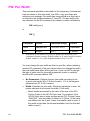
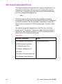
The vector graphics commands have been grouped into functional
categories. The categories are designated as shown in Table 17-1
through . Each of the command categories is discussed in its own
chapter, beginning with Chapter 19, The Configuration and Status
Group.
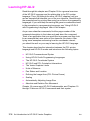
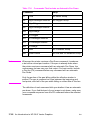
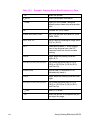
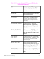
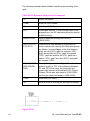
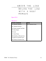
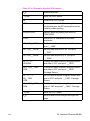
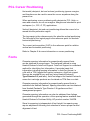
Table 17-1
The HP-GL/2 Commands by Group (1 of 5)
CONFIGURATION GROUP
CO
Comment
DF
Default Values
IN
Initialize
IP
Input P1 and P2
IR
Input Relative P1 and P2
IW
Input Window
PG1
Advance Page
RO
Rotate Coordinate System
RP1
Replot
SC
Scale
1. Ignored by HP LaserJet printers.
EN
HP-GL/2 Commands and Syntax 17-3
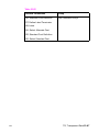
Table 17-2
The HP-GL/2 Commands by Group (2 of 5)
VECTOR GROUP
AA
Arc Absolute
AR
Arc Relative
AT
Absolute Arc Three Point
BR
Bezier Relative
BZ
Bezier Absolute
CI
Circle
PA
Plot Absolute
PD
Pen Down
PE
Polyline Encoded
PR
Plot Relative
PU
Pen Up
RT
Relative Arc Three Point
Table 17-3
The HP-GL/2 Commands by Group (3 of 5)
POLYGON GROUP
EA
Edge Rectangle Absolute
EP
Edge Polygon
ER
Edge Rectangle Relative
EW
Edge Wedge
FP
Fill Polygon
PM
Polygon Mode
RA
Fill Rectangle Absolute
RR
Fill Rectangle Relative
WG
Fill Wedge
17-4 An Introduction to HP-GL/2 Vector Graphics
EN
Table 17-4
The HP-GL/2 Commands by Group (4 of 5)
CHARACTER GROUP
AD
Alternate Font Definition
CF
Character Fill Mode
CP
Character Plot
DI
Absolute Direction
DR
Relative Direction
DT
Define Label Terminator
DV
Define Variable Text Path
ES
Extra Space
FI1
Select Primary Font
FN1
Select Secondary Font
LB
Label
LO
Label Origin
SA
Select Alternate Font
SB
Scalable or Bitmap Fonts
SD
Standard Font Definition
SI
Absolute Character Size
SL
Character Slant
SR
Relative Character Size
SS
Select Standard font
TD
Transparent Data
1. These commands are part of HP-GL/2’s Dual Context Extensions.
EN
HP-GL/2 Commands and Syntax 17-5
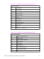
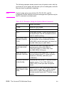
Table 17-5
The HP-GL/2 Commands by Group (5 of 5)
LINE AND FILL ATTRIBUTES GROUP
AC
Anchor Corner
FT
Fill Type
LA
Line Attributes
LT
Line Type
PW
Pen Width
RF
Raster Fill Definition
SM
Symbol Mode
SP
Select Pen
SV1
Screened Vectors
TR1
Transparency Mode
UL
User-defined Line Type
WU
Pen Width Unit Selection
1. These commands are part of the Palette Extensions to HP-GL/2.
As shown in the tables above, each HP-GL/2 command is a two-letter
mnemonic code designed to remind you of its function. For example,
IN is the Initialize command, SP is the Select Pen command, and CI
is the Circle command. Parameters are used with certain HP-GL/2
commands to tell the printer to complete the command in a particular
way.
Understanding HP-GL/2 Syntax
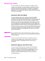
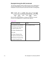
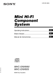
HP-GL/2 commands have four components: a mnemonic,
parameter(s), separator(s), and a terminator. Refer to the following
illustration of a typical HP-GL/2 command and the description of its
components.
17-6 An Introduction to HP-GL/2 Vector Graphics
EN
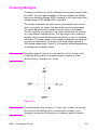
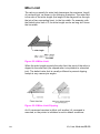
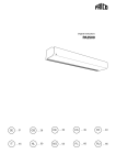
Figure 17-1 Typical HP-GL/2 Command
z
Mnemonic--The two-letter mnemonic reminds you of the
command’s function. The mnemonic can be uppercase or
lowercase.
z
Parameter(s)--Some commands have no parameters; for those
commands which have them, parameters can be either required
or optional (as indicated in the description of that command).
z
Separator(s)--When you use parameters, you must separate
them with a comma or space, or in the case of a numeric
parameter, with a + or - sign. (Commas are recommended
because some computers eliminate spaces, especially when
sending variables.)
z
Terminator--All commands require a terminator. Most HP-GL/2
commands are terminated by a semicolon or the first letter of the
next mnemonic, a white space, or a tab (exceptions: LB uses a
user-defined terminator; PE cannot use the first letter of the next
mnemonic). The last command prior to exiting HP-GL/2 mode
must be terminated with a semicolon.
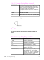
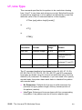
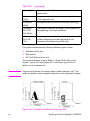
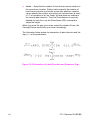
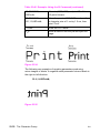
The following illustration shows the flexibility of the syntax. Each
variation of the two-command sequence is permissible; however, the
method shown on the left is recommended in most instances. The
recommended method uses the first letter of the next mnemonic to
terminate commands, uses no space between the mnemonic and its
parameters, and separates parameters with a comma. (For clarity,
examples in this HP-GL/2 section of the manual use semicolons as
terminators, as shown in the middle example below.)
Figure 17-2 Illustration of Syntax Flexibility
EN
HP-GL/2 Commands and Syntax 17-7
The next section explains how the syntax of individual commands is
presented.
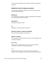
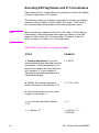
Notations Used to Express Syntax
The following describes the notations used in the syntax section of
each command description:
Mnemonic
For readability, the mnemonic is shown in uppercase and separated
from the parameters and/or terminator.
parameters
Parameters are shown in italic.
[]
Parameters in square brackets are optional.
[param1,param2...[,param1,param2]]
These optional parameters must be paired.
params...params
These parameters may be given the number of times specified in the
command description.
text...text
This parameter indicates that you can type in a range of ASCII
characters, such as in the Label (LB) command.
(....)
Indicates that you can use a range of the previous parameter;
however, all X coordinates must have a corresponding Y coordinate.
17-8 An Introduction to HP-GL/2 Vector Graphics
EN
Note
Remember that while X,Y coordinates are shown in parentheses in
text [for example (3,4) or (0,0)], the parentheses are not part of the
syntax. Do not enter these parentheses in your commands.
;
iCommand terminator. In most HP-GL/2 commands, a semicolon is
optional, and is shown in parentheses in most command syntax.
Notes
Three exceptions to the optional use of the semicolon as a command
terminator occur in the following commands: Polyline Encoded (PE),
Label (LB), and Comment (CO).
PE must be terminated by a semicolon. LB is terminated by the nonprinting end-of-text character (ETX - decimal 3), or a user-defined
character. The comment string of the CO command must be delimited
by double quotes.
A semicolon terminator is always required following the last
command prior to leaving HP-GL/2 mode.
,
A comma is always shown as the separator between parameters. A
space, +, or - is also valid (although not preferred). (A + or - is a valid
separator only for numeric parameters.)
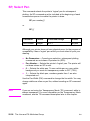
Omitting Optional Parameters
Some commands have optional parameters that take on default
values if they are omitted. When you omit a parameter, you must omit
all subsequent parameters in the same command (the Define Label
Terminator (DT) command is an exception).
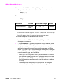
For example, the Line Type (LT) command has three optional
parameters: type, pattern length, and mode. The following command
shows all three being used (type = 6, pattern length = 25, mode = 1).
LT6,25,1
EN
HP-GL/2 Commands and Syntax 17-9
If you omit the second parameter you must also omit the third
parameter, as shown below:
LT6
The printer uses the most recently specified pattern length and mode.
If you have not specified a length or mode since sending a Default
Values (DF) or Initialize (IN) command, the printer uses the
parameter’s defaults.
For example, if you send the following command (omitting the second
parameter), the printer interprets the “1” as the second parameter:
LT6,1
Parameter Formats
You must give parameters in the format (type of units) required by
each HP-GL/2 command. The required format is stated in the
parameter table of each command’s description, and is described as
follows.
1
Integer—An integer from –1,073,741,823 (–230 +1) to
1,073,741,823 (230 – 1). The printer automatically rounds
fractional parameters to the nearest integer within the range.
Sending a number outside the parameter range may produce
unexpected results.
2
Clamped Integer—An integer from –32,768 (–215) to 32,767
(215 –1). The printer automatically rounds fractional parameters
to the nearest integer. Sending a number outside this range does
not cause an error, but the number is “clamped” to the limits of the
range. For example, when parsing a clamped integer, the printer
treats all numbers above 32,767 as 32,767.
Certain commands have parameters which are restricted to a smaller
range. These ranges are listed in the parameter tables for each
command. Sending a number outside the reduced parameter range
may produce unexpected results.
3
Real—A number with an integer portion from –1,073,741,823
(–230 +1) to 1,073,741,823 (230 – 1). You are assured of at least
6 significant digits (including integer and fractional portion). You
may omit the decimal point when no decimal fraction is specified.
Sending a number outside the parameter range may produce
unexpected results.
17-10 An Introduction to HP-GL/2 Vector Graphics
EN
4
Clamped Real—A number with an integer portion from –32,768
to 32,767; you are assured of at least 6 significant digits
(including integer and fractional portion). You may omit the
decimal point when no decimal fraction is specified. Sending a
number outside this range does not cause an error, but the
number is “clamped” to the limits of the range. For example, the
printer treats all numbers above 32,767 as 32,767.
Certain commands have parameters which are restricted to a
smaller range. These ranges are listed in the parameter tables
for each command. Sending a number outside the reduced
parameter range may produce unexpected results.
5
Note
Label—Any sequence of characters. In the HP-GL/2 language,
text is described using the term “label.” Refer to the Label (LB)
command in Chapter 23 for a complete description.
Numbers within the above-mentioned ranges do not cause errors;
however, the range may exceed the printer’s physical printing area.
Numbers that move the pen position outside the effective window
result in image clipping. This topic is discussed in more detail later
in this chapter under “The Vector Graphics Limits.”
When you see the term “current units” in a parameter table, the unit
system of that parameter depends on whether scaling is on or off.
When scaling is on, the units are user-units; when scaling is off, the
units are plotter units (described under “Units of Measure” later in
this chapter).
Notes
The printer cannot use exponential format numbers (for example,
6.03E8). If you are using a computer or language that uses the
exponential format, you must use integer variables or a formatting
technique to output fixed-point real numbers.
Parameter values less than the range maximum are passed by the
parser; these values may subsequently be unscaled into resolution
units (e.g. 7200 units-per-inch) that exceed the device-dependent
internally representable number range. If this occurs, the device
enters a LOST mode; all relative drawing commands are ignored until
a command is received which specifies an absolute move to a point
within the internally representable number range.
EN
HP-GL/2 Commands and Syntax 17-11
Notes
When LOST mode is entered, the pen is raised and the following
commands are ignored: AA, AR, AT, CI, CP, EA, ER, EW, LB, PE, PM,
PR, RA, RR, RT, and WG.
The commands allowed in LOST mode are: AC, AD, CF, CO, DF, DI,
DR, DT, DV, ES, FT, IN, IP, IR, IW, LA, LO, LT, PA, PD, PG, PU, PW,
RF, RO, RP, SA, SB, SC, SD, SI, SL, SM, SP, SR, SS, TD, UL, WU,
and the PM1/PM2 forms of PM.
The commands IN, PG, RP, and PA, with in-range parameters, clear
LOST mode, PD and PU in absolute plotting mode, with in-range
parameters, also clear LOST mode. When PD clears LOST mode, a
line is drawn from the last valid current position to the first point in the
PD parameter sequence. If PA clears LOST mode, the pen will not go
down until a PD command is received.
17-12 An Introduction to HP-GL/2 Vector Graphics
EN
Using HP-GL/2 With Programming Languages
The HP-GL/2 examples included in this manual are given in a
“generic” format (they show the commands required to perform a
specific function but usually do not use a specific programming
language). In most cases, the commands are accompanied by a brief
description of the command being used.
To see how HP-GL/2 commands are used in BASIC and the C
programming language, see the following examples.
Example:BASIC
This example uses BASIC to print three lines forming a simple
triangle (shown below).
10
20
30
40
50
60
70
LPRINT
LPRINT
LPRINT
LPRINT
LPRINT
LPRINT
LPRINT
CHR$(27);“E”; :REM Reset the printer
CHR$(27);“%0B”; :REM Enter HP-GL/2 Mode
“IN”; :REM Initialize HP-GL/2 Mode
“SP1PA10,10”; :REM Select Pen & move to 10,10
“PD2500,10,10,1500,10,10;”; :REM Pen down & draw
CHR$(27);“%0A”; :REM Enter PCL Mode
CHR$(27);“E”; :REM Reset to end job/eject page
Figure 17-3
EN
Using HP-GL/2 With Programming Languages 17-13
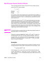
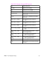
Example:C Programming Language
This example uses the C programming language to print the same
three lines shown on the previous page.
Table 17-6
#include <stdio.h>
main()
{
FILE *prn;
prn = fopen(“PRN”,“wb”);
fprintf(prn,“033E”);
fprintf(prn,“033%%>0B”);
fprintf(prn,“IN”);
fprintf(prn,“SP1PA10,10”);
fprintf(prn,“PD2500,10,10,1500,10,10;”);
fprintf(prn,“033%%0A”);
fprintf(prn,“033E”);
}
17-14 An Introduction to HP-GL/2 Vector Graphics
/* open the printer */
/* EC E to reset printer */
/* Enter HP-GL/2 */
/* Initialize HP-GL/2 Mode */
/* Select pen 1 & move to 10,10 */
/* Pen down & draw */
/* enter PCL at previous CAP */
/* Reset to end job/eject page */
EN
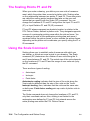
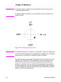
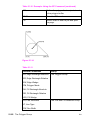
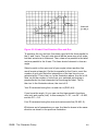
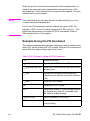
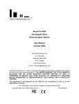
The HP-GL/2 Coordinate System
Both PCL and HP-GL/2 use a Cartesian Coordinate System. The
Cartesian coordinate system is a grid formed by two perpendicular
axes, usually called the X-axis and Y-axis (refer to Figure 17-4). The
intersection of the axes is called the origin of the system and has a
location of (0,0). The default HP-GL/2 coordinate system is different
than the PCL coordinate system; +Y is down in PCL and up in
HP-GL/2. In addition, the default origin is at the lower left in HP-GL/2
and at the upper left in PCL.
Note
The HP-GL/2 coordinate system can be set up to match the PCL
coordinate system. See the example entitled “Adapting the HP-GL/2
Coordinate System to Match the PCL System” in Chapter 19.
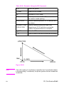
Figure 17-4 The HP-GL/2 Coordinate System
To locate any point on the grid (the printing area within the PCL
Picture Frame), move from the origin a number of units along the
X-axis, then move a number of units parallel to the Y-axis. The
number of units you move matches a coordinate location. Each
point is designated by the combination of its X-coordinate and
Y-coordinate, known as an X,Y coordinate pair. In , positive X
values are plotted to the right of the origin, and positive Y values
are plotted above the origin.
EN
The HP-GL/2 Coordinate System 17-15
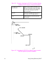
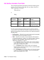
Study Figure 17-4 to locate these points: (0,0); (-2,2); (6,2); (6,3);
(10,0); (6,-3); (6,-2); (-2,-2); (0,0). Draw a straight line between each
point in the order listed. (You should have drawn an arrow.) This is a
simple demonstration of defining a vector image when in HP-GL/2
mode.
Note
To specify a point when programming an application, you must
always give a complete X,Y coordinate pair; the X coordinate is first
and the Y coordinate second. This manual shows coordinate pairs
in parentheses (X,Y) for clarity. Do not use parentheses in your
command sequence.
Using the default HP-GL/2 coordinate system, the origin is in the
lower left corner of the PCL Picture Frame, as shown in Figure 17-5.
Using the IP or IR commands, you can move the origin to other
locations. Then, using the SC command, you can define practically
any unit coordinate system. (This process is discussed in more
detail later in this chapter under “Scaling,” and also in Chapter 19.)
Figure 17-5 The Default HP-GL/2 Coordinate System
17-16 An Introduction to HP-GL/2 Vector Graphics
EN
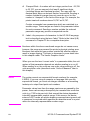
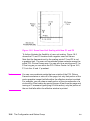
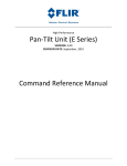
HP-GL/2 & PCL Orientation Interactions
The relationship between the orientation of the HP-GL/2 coordinate
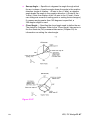
system and the PCL coordinate system is important. Figure 17-6
illustrates this relationship for the default HP-GL/2 orientation (RO 0)
and the PCL logical page orientation. As shown in the illustration, in
the default HP-GL/2 orientation, the origin of the HP-GL/2 coordinate
system defaults to the lower-left corner of the PCL Picture Frame.
(HP-GL/2 and PCL X-coordinates increase in the same direction,
but the Y-coordinates increase in opposite directions.) Notice that a
change in the PCL logical page orientation changes the orientation
of the PCL coordinate system and the HP-GL/2 coordinate system.
Figure 17-6 Orientation Interactions Between PCL and HP-GL/2
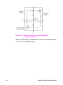
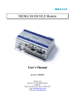
The relationship between the coordinate systems can be changed
using the HP-GL/2 Rotate (RO) command. Rotations specified by the
RO command are relative to the default HP-GL/2 orientation (which
matches the PCL orientation). Figure 17-7 shows how the RO
command modifies the default HP-GL/2 orientation.
Note
EN
A change in PCL print direction has no effect on the HP-GL/2
orientation, the physical position of the picture frame, or the picture
frame anchor point.
HP-GL/2 & PCL Orientation Interactions 17-17
Figure 17-7 Modifying HP-GL/2 Orientation on a Portrait Page
17-18 An Introduction to HP-GL/2 Vector Graphics
EN
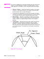
The Vector Graphics Limits
The area on the page where a vector graphics image can be printed
is determined by the intersection of the following four boundaries:
z
Hard-clip Limits
z
Soft-clip Window
z
PCL Logical Page
z
PCL Picture Frame
The hard-clip limit refers to the boundaries resulting from the physical
limits of the printer (in PCL mode, this is referred to as the printable
area). The soft-clip limit refers to the area defined using the HP-GL/2
Input Window (IW) command. The intersection of all these areas is
the effective window. An HP-GL/2 graphic appears on the page only
if it falls within the effective window.
Figure 17-8 The Effective Window
Note
EN
For more information on the PCL coordinate system and the PCL 5
printer’s printable limits, see Chapter 2.
The Vector Graphics Limits 17-19
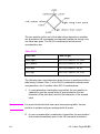
HP-GL/2 Units of Measure
In HP-GL/2 mode, you can measure along the X,Y axes and express
coordinates using two types of units: plotter units and user-units.
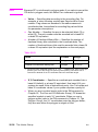
Plotter Units
One plotter unit equals 0.025 mm. When specifying distances in
plotter units, the printer converts the number of plotter units to
equivalent dot coordinates before printing. Under default conditions,
the printer uses plotter units.
The following table lists equivalent measurements for plotter units.
Table 17-7
PlotterUnits
EquivalentValue
1 plu =
0.025 mm (≈ 0.00098 in.)
40 plu =
1 mm
1016 plu =
1 in.
3.39 plu =
1 dot @ 300 dpi
User-units
The size of units along the X and Y axes may be redefined using
the Scale (SC) command. User-units allow you to customize the
coordinate system to represent any value. For example, you could
plot the moon cycle for the year by dividing the X-axis into 31 units for
days of the month and the Y-axis into 12 units for months of the year.
To mark a point on December 25, you would give the coordinate
(25,12) rather than calculating the exact location in plotter units.
Before printing, the printer internally converts user-units to dot
locations.
17-20 An Introduction to HP-GL/2 Vector Graphics
EN
Pen Status and Location
Since printing vector graphics has traditionally been performed with
plotters, the terms pen and pen position are used to described the
HP-GL/2 cursor, the current active position (CAP) when in HP-GL/2
mode. Like a physical pen, this imaginary pen must be selected if you
want to draw images. Commands such as Pen Up (PU) or Pen Down
(PD), and phrases such as “current pen position” or “moving the pen”
apply to the imaginary pen just as they would a physical pen on a
plotter.
Pen Status
Pen status refers to whether the “pen” is up or down. Use the Pen
Up (PU) command with X,Y coordinates to move the pen to the
desired printing location without drawing a line. Use the Pen Down
(PD) command with X,Y coordinates to lower the pen and begin
drawing from the current location to the first specified X,Y coordinate.
Upon entering HP-GL/2 mode for the first time following a reset (ECE)
command, no pen has been selected and the pen is up. This means
that no lines are drawn when HP-GL commands are given until a pen
is selected. This can be done using the Select Pen (SP) command.
Most drawing commands require that the pen be lowered to produce
marks on the page. Once lowered with a Pen Down (PD) command,
the pen remains down for subsequent HP-GL/2 printing commands
until a Pen Up (PU) or Initialize (IN) command is issued. The pen
remains selected until a new SP command is received. You must be
aware of the pen’s up/down status to avoid drawing stray lines
between parts of your picture.
Note
Upon entry into HP-GL/2 mode, a good programming practice is to
select a pen and command a pen-up move to the initial starting
position. This ensures that a pen is selected and is in the proper
position to begin drawing.
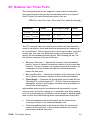
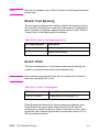
Every time you use a PU or PD command, the printer updates the
pen up/down status. The following table shows the commands that
include an automatic PD command as part of their function. After
performing their complete function, they return the pen to its previous
up/down state.
EN
Pen Status and Location 17-21
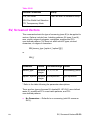
Table 17-8
Notes
Commands That Include an Automatic Pen Down
Command
Group
CI
Circle
The Vector Group
EA
Edge Rectangle Absolute
The Polygon Group
EP
Edge Polygon
ER
Edge Rectangle Relative
EW
Edge Wedge
FP
Fill Polygon
RA
Fill Rectangle Absolute
RR
Fill Rectangle Relative
WG
Fill Wedge
LB
Label
The Character Group
SM
Symbol Mode
The Line and Fill Attributes Group
Whenever the printer receives a Pen Down command, it produces
a dot at the current pen location. If the pen is already down when
the printer receives a command with an automatic Pen Down, the
unnecessary dot can mar your final output. For best results, include
a Pen Up (PU) command before any command with an automatic
Pen Down.
Only the portion of the pen falling within the effective window is
printed. The pen is centered on a line between the beginning and
end points, with half of the pen width falling on either side of this line.
The definition of each command tells you whether it has an automatic
pen down. If you find that part of your image is not drawn, make sure
your command sequence uses the PD command before the affected
commands.
17-22 An Introduction to HP-GL/2 Vector Graphics
EN
Pen Location
Pen location refers to the X,Y coordinates of the current active
position (CAP — the point at which the next HP-GL/2 command
begins). Most commands, when completed, update the pen location.
The next command then begins at that location. Some commands do
not update the current pen location. The definition of each command
tells you whether the current pen location is updated or restored. Use
the Pen Up (PU) command with the desired X,Y coordinates to lift the
pen and move it to a new location.
The Default Values (DF) command does not reset the current pen
location; the Initialize (IN) command moves it to the lower-left corner
of the PCL Picture Frame. You should specify your beginning pen
location for each HP-GL/2 drawing.
EN
Pen Status and Location 17-23
Scaling
When you scale a drawing, you define your own units of measurement instead of using plotter units; the printer converts your units
(user-units) to dot positions for placing the image on the page.
Scaling allows control of the printer using units that are easy for
you to work with.
For example, you can scale your drawing to divide the drawing area
into 100 squares. As you plan the drawing, you can think in terms
of 100 squares rather than plotter units. Here is another example of
scaling: since 400 plotter units equals 1 centimeter, you can establish
this scale to print in user-units equal to 1 centimeter each.
Scaling begins with the scaling points, P1 and P2. P1 and P2 act as
two points marking opposite corners of a rectangle. You can make
this rectangle any size and place it anywhere in relation to the origin,
depending on the plotter unit coordinates you specify for P1 and P2.
(P1 and P2 default to the lower left and upper right corners of the
picture frame, respectively, but you can change their locations using
the Input P1 and P2 (IP) or Input Relative P1 and P2 (IR) commands.)
After you have defined the positions for P1 and P2, or have accepted
the default, use this imaginary rectangle to set up scaling for your
drawing. With the Scale (SC) command you specify how many
sections the rectangle divides into horizontally (the X-axis) and how
many sections the rectangle divides into vertically (the Y-axis). With
this process you have created your user-units.
Scaling also allows you to enlarge or reduce your image by changing
the locations of P1 and P2. P1 and P2 represent physical locations
in relation to the PCL Picture Frame. When the imaginary rectangle
formed by P1 and P2 is enlarged or reduced with the IP or IR
commands, the HP-GL/2 image is also enlarged or reduced to fit the
new P1/P2 rectangle. (For a more detailed explanation of scaling
and the Scale (SC) command, see Chapter 19.)
For importing existing HP-GL/2 images, another method of enlarging
or reducing drawings exists. It involves varying the size of the PCL
Picture Frame and is described next. This method allows you to scale
an image while maintaining the aspect ratio of all elements (including
fonts). The Scale command does not affect the size of fonts.
17-24 An Introduction to HP-GL/2 Vector Graphics
EN
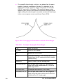
Absolute and Relative Pen Movement
The Plot Absolute (PA) and Plot Relative (PR) commands allow you to
set whether you want to draw using absolute or relative “pen” moves.
Absolute pen movement uses X,Y coordinates to specify an exact,
fixed point relative to the origin (0,0). In Figure 17-9, the coordinates
(3,8), (5,4), and (8,1) are always in the same place with respect to the
origin, no matter where the pen is when the coordinates are issued.
Figure 17-9 Absolute Coordinates
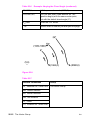
Relative pen movement uses X,Y increments to specify the number
of units the pen moves from its current pen location. All commands
that use relative increments include “relative” in their name (except
the PE command). (An example is the Edge Rectangle Relative
(ER) command.
In Figure 17-10 for example, assume that the pen is currently at the
origin (0,0). To move to the absolute points shown in Figure 17-9
using relative coordinates, count 3 units to the right and 8 units up
from the current pen location; these are both positive directions with
respect to the origin. This is the relative location (3,8). Now move 5
positive X-units and 7 negative Y-units from this location to the lower
point; this is the relative location (5,-7). From this location, move to
the last point by moving 3 negative X-units and 3 positive Y-units
(-3,3).
EN
Absolute and Relative Pen Movement 17-25
Figure 17-10Relative Coordinates
Relative movement is useful in many applications where you know
the dimensions of the shape you want, but do not want to calculate
the absolute coordinates. For example, if you want a box 4 X-units by
8 Y-units, you can use the Edge Rectangle Relative (ER) command to
draw the box without having to calculate the absolute coordinates of
the opposite corner. (The ER command draws a rectangle using the
current pen location as one corner, and the specified relative
coordinates as the opposite corner.)
Absolute pen movement is the default mode; coordinates received
within a PU (Pen Up) or PD (Pen Down) command are interpreted
as absolute plotter units unless a PR (Plot Relative) command
establishes relative mode. As with absolute coordinates, the relative
units can be either user-units or plotter units, depending on whether
the SC command is in effect.
Note
Relative increments add to the current pen location. The printer
automatically converts the new relative location to absolute
coordinates and updates the current pen location. Using relative
coordinates can be faster in cases where the I/O speed limits your
print speed, since relative coordinates are generally smaller
numbers and therefore transmit less data over the I/O.
17-26 An Introduction to HP-GL/2 Vector Graphics
EN
18
The Picture Frame
Introduction
When importing an existing HP-GL/2 file, or creating an HP-GL/2
image within an application, you use several PCL commands to
set up the picture frame size, choose the picture frame location,
and enter and exit HP-GL/2 mode. This chapter explains these
PCL commands.
The following terms are used in this discussion:
Picture presentation directives are a group of PCL commands
which:
z
Provide the means to enter and exit HP-GL/2 context.
z
Define a delimiting rectangle for the graphic image.
z
Specify a scaling factor so existing HP-GL/2 graphics can
be scaled and placed anywhere on the PCL logical page.
Picture frame refers to the destination rectangle when
transferring HP-GL/2 graphics into the PCL logical page.
The PCL picture frame size commands specify the size of
the destination rectangle.
Picture frame scaling factor is the ratio of the size of the picture
frame to the size of the source HP-GL/2 plot. There may actually
be two scaling factors, one for the x direction and one for the
y direction.
Picture frame anchor point refers to the upper left corner of the
picture frame, which is set to the current active position (CAP) in
the PCL environment at the time the picture frame anchor point
command is executed.
EN
Introduction 18-1
Defining the Image Area(PCL Picture Frame)
There is a group of commands that allows you to specify an area on
the page for placing an HP-GL/2 graphic image. These commands
are the Picture Presentation Directives and are used to define a
bounding rectangle to contain the HP-GL/2 image.
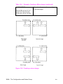
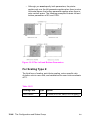
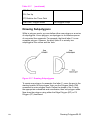
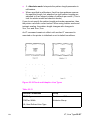
Figure 18-1 illustrates the Picture Presentation Directives. The
rectangular area surrounding the image is the PCL Picture Frame
and the location on the page of the PCL Picture Frame is determined
by the picture frame anchor point. Refer to Figures 2-3 and 2-4 for
the default picture frame size.
Figure 18-1 The Picture Presentation Directives
18-2 The Picture Frame
EN
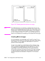
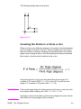
Automatically Adjusting Image Size to Fit the PCL
Picture Frame
FrameImported HP-GL/2 drawings can be adjusted automatically to
fit the size of the PCL Picture Frame without changing the locations of
P1 and P2 (in Scale mode, as described earlier). This is called picture
frame scaling.
When using picture frame scaling, specify the HP-GL/2 plot size
unless the drawing is page size-independent (described below).
If a drawing is not page size-independent, the printer will not adjust
the size of the image to fit the picture frame without the HP-GL/2 plot
size command; the drawing and the picture frame are assumed to be
the same size. If a drawing is page size-independent, it automatically
enlarges or reduces to fit within the picture frame without specifying
an HP-GL/2 plot size.
Creating a Page Size-Independent Plot
As mentioned, if an imported HP-GL/2 drawing is page sizeindependent, it is adjusted automatically to fit different page sizes
without specifying the HP-GL/2 plot size. For a drawing to be page
size-independent, it must not specify any parameters in absolute
units. This implies that:
EN
z
No parameter of any command is in plotter units. The scaled
mode (SC command) must be used exclusively; either the default
locations of P1 and P2 are used, or their positions are specified
with the IR (Input Relative P1 and P2) command. The default
window is used, or the window is specified in user-units (using
the IW command).
z
For labels, only the SR (Relative Character Size) mode is used;
the SI (Absolute Character Size) mode is not used.
z
The Pen Width selection mode (WU) is specified as relative
instead of metric.
z
The pattern length for the Line Type (LT) is specified as relative
instead of metric.
z
Scalable fonts are used exclusively.
z
The default window is used, or the window is specified in
user-units.
z
The DR command (relative direction) is used for label direction
(not DI — absolute direction).
Automatically Adjusting Image Size to Fit the PCL Picture Frame 18-3
If a drawing does not meet the above criteria and the drawing is not
the same size as the picture frame, the HP-GL/2 plot size must be
specified to accomplish the desired scaling. If it is not specified, the
image is clipped to the effective window and no scaling occurs.
Note
The above bulleted items are required for automatic scaling when the
picture frame size changes, without specifying the HP-GL/2 plot size.
However, if an HP-GL/2 plot size is specified, any unscaled HP-GL/2
image (any image created without the SC command) is automatically
enlarged or reduced to fit the PCL Picture Frame; the amount of
enlargement or reduction is determined by the picture frame scaling
factor (the ratio of the HP-GL/2 plot size to the PCL Picture Frame
size). See Chapter 19 to specify an HP-GL/2 plot size.
18-4 The Picture Frame
EN
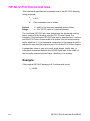
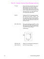
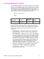
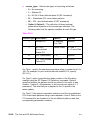
Typical HP-GL/2 PlotCommand Sequence
Before we discuss the actual commands and how they operate, we
will demonstrate the general sequence in which these commands are
used to print HP-GL/2 files.
The following command sequence is usually followed when creating
HP-GL/2 images:
Note
EN
z
Send the job control and page control commands, and any
other PCL commands that you wish to send before drawing the
HP-GL/2 image. (See Chapters 3, 4, and 5 for job control and
page control information.)
z
Specify the PCL Picture Frame dimensions using the EC*c#X
(Picture Frame Horizontal Size) and EC*c#Y (Picture Frame
Vertical Size) commands. These commands determine the
boundary of the window in which you place or draw your image.
The PCL Picture Frame represents the maximum boundary for
your HP-GL/2 drawing.
z
Specify the picture frame anchor point using the EC*c0T
(Set Picture Frame Anchor Point) command. This command
determines the position on the logical page where the upper
left corner of the PCL Picture Frame is placed. Receipt of this
command establishes the PCL picture frame anchor point at
the PCL current cursor position.
z
If importing an existing plot, defined in absolute units, specify
the HP-GL/2 plot size using the ECEC*c#K (Horizontal HP-GL/2
Plot Size) and EC*c#L (Vertical HP-GL/2 Plot Size). This plot size
represents the size of the original HP-GL/2 image. If you are
creating a drawing within an application, do not send these
commands.
z
Enter HP-GL/2 mode using the EC%#B command.
z
Send HP-GL/2 commands (IN;SP1;. . .).
z
Exit HP-GL/2 mode by sending the EC%#A (Enter PCL Mode)
command.
z
Send more PCL commands if desired or issue an ECE command
to end the job and eject the page.
Whenever a printer reset (ECE) is sent at the beginning of a job,
precede it with a UEL (EC%–12345X) command; whenever a printer
reset is sent at the end of a job, follow it with a UEL command.
Typical HP-GL/2 PlotCommand Sequence 18-5
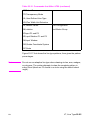
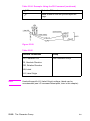
Table 18-1
Example: Creating and Using a PCL Picture Frame
E
CE
Reset the printer.
E
C&l2A
Set the page size to letter.
E
C&l0O
Specify portrait orientation.
E
C*c3060x3960Y
Specify a 4.25-inch wide by 5.5-inch
high PCL Picture Frame (4.25in. x 720
decipoints/in. = 3060 decipoints; 5.5in.
x 720 decipoints/in. = 3960 decipoints).
E
C*p565x600Y
Move the cursor to the point you desire
as the picture frame anchor point.
E *c0T
C
Set the picture frame anchor point to
the current cursor position.
E
C*c8.5k11L
Specify that the original HP-GL/2 plot
size is 8.5 inches wide by 11 inches
high. This sets up a scaling factor of 2:1
because the original HP-GL/2 plot size
is twice as large as the PCL Picture
Frame (4.25 x 5.5 inches). (If you are
creating a drawing within an application
instead of importing an existing plot, do
not send this command.)
E
C%1B
Enter HP-GL/2 mode with the pen
(HP-GL/2 cursor) at the PCL cursor
position. In this example, the cursor
would be at the picture frame anchor
point (600 PCL Units down from the top
of the logical page and 565 PCL Units
to the right of the left logical page
boundary).
18-6 The Picture Frame
EN
Table 18-1
Example: Creating and Using a PCL Picture Frame
IN;SP1;PU50,50;
Send the HP-GL/2 commands you
desire to send. (The IN command
defaults the pen position to the
HP-GL/2 origin, the lower-left corner
of the PCL Picture Frame.)
E
C%1A
Enter the PCL mode with the cursor at
the current HP-GL/2 pen position.
TextTextText
Send some text or more PCL
commands.
E
CE
Reset the printer to end the job and
eject a page.
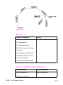
Figure 18-2
The previous example provides an idea of the commands involved
in printing an HP-GL/2 plot, whether importing an existing drawing or
creating one within an application. The example describes one way to
print a plot, but many things can be varied such as the picture frame
size and location, and the cursor position when entering and leaving
HP-GL/2 mode.
EN
Typical HP-GL/2 PlotCommand Sequence 18-7
Note
If you have a page size-independent HP-GL/2 image, there is no need
to set plot size, otherwise it is good practice to set plot size.
The commands that allow you to set up a PCL Picture Frame and
enter/exit HP-GL/2 mode are discussed in detail in the rest of this
chapter. By reading the following command descriptions, you can see
how changing command parameters can affect your printed output.
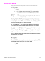
Horizontal Picture Frame Size
This PCL command specifies the horizontal dimension of the window
to be used for printing an HP-GL/2 plot.
E
C*c#X
#
Default
Range
Note
=Horizontal size in decipoints (1/720th inch)
= width of the current logical page
= 0 - 32767 (valid to 4 decimal places)
The horizontal dimension specified is parallel to the PCL X-axis
when the print direction is set to 0 degrees (the default).
Using this command defaults the location of P1 to the lower left
corner of the picture frame, and P2 to the upper right corner of the
picture frame. It also resets the soft-clip window to the PCL Picture
Frame boundaries, clears the polygon buffer, and updates the
HP-GL/2 pen position to the lower-left corner of the picture frame
(P1), as viewed from the current orientation.
If no horizontal picture frame size command is used, the printer
defaults the picture frame size to the logical page width. A parameter
value of 0 or the PCL reset, UEL, page length, paper size, or
orientation commands default the horizontal picture frame size.
If an HP-GL/2 plot size is specified, the horizontal picture frame size
is used to determine the horizontal scaling factor used for scaling the
image to fit in the picture frame.
18-8 The Picture Frame
EN
Example:
To specify a horizontal picture frame size of 5 inches, send:
E
C*c3600X
(5 in. x 720 decipoints/in. = 3600 decipoints).
Vertical Picture Frame Size (Decipoints)
This PCL command specifies the vertical dimension of the window
used for printing an HP-GL/2 plot.
E
C*c#Y
#
Default
= The distance between the default top and bottom
margins (the default text length)
= 0 - 32767 (valid to 4 decimal places)
Range
Note
=Vertical size in decipoints (1/720th inch)
The vertical dimension specified is parallel to the PCL Y-axis when
the print direction is set to 0 degrees (the default).
Example:To specify a vertical picture frame
size of 6.5 inches, send:
E
C*c4680Y
(6.5 in. x 720 decipoints/in. = 4680 decipoints)
EN
Vertical Picture Frame Size (Decipoints) 18-9
Set Picture Frame Anchor Point
This command sets the location of the PCL Picture Frame anchor
point to the PCL cursor position.
E
C*c0T
Default
Range
= 0
= 0
The position of the picture frame anchor point defines the location of
the upper left corner of the PCL Picture Frame. The “upper left” refers
to the corner for which X and Y coordinates are minimized when the
print direction is 0.
A parameter value of zero (EC*c0T) specifies that the picture frame
anchor point should be set to the cursor position. Sending a cursor
move command prior to sending this command places the picture
frame anchor in the desired location. All parameter values other than
zero are ignored, but if you do not send a Set Picture Frame Anchor
command, the printer defaults the anchor point to the left edge of the
logical page and the default top margin.
Note
The print direction command does not affect the physical location of
the anchor point or the picture frame.
Using this command defaults the location of P1 and P2, resets the
soft-clip window to the PCL Picture Frame boundaries, clears the
polygon buffer, and updates the HP-GL/2 pen position to the lower
left corner of the picture frame (if entered with EC%0B), as viewed
from the current orientation.
Example:
To set the picture frame anchor point to a position 6 inches from the
left logical page boundary and 5 inches below the top margin, send:
E
E
C*p1800x1500Y C*c0T
In this example, the cursor is first moved to the desired location (6
inches x 300 dots/inch = 1800 dots; 5 inches x 300 dots/inch = 1500
dots). Then the EC*c0T command sets the picture frame anchor point
to that location.
18-10 The Picture Frame
EN
HP-GL/2 Plot Horizontal Size
This command specifies the horizontal size of the HP-GL/2 drawing
being imported.
E
C*c#K
#
Default
Range
=The horizontal size in inches
= width of the currently selected picture frame
= 0 to 32767 (valid to 4 decimal places)
The horizontal HP-GL/2 plot size determines the horizontal scaling
factor used to fit the drawing into the PCL Picture Frame. For
example, if the horizontal HP-GL/2 plot size is specified as 12 inches
and the PCL Picture Frame width is 4 inches, the horizontal scaling
factor would be 3:1; the horizontal component of the image would be
reduced to one-third its original size to fit into the PCL Picture Frame.
A parameter value of zero or a reset, page length, paper size, or
orientation command defaults the HP-GL/2 plot size to the width of
the currently selected picture frame, resulting in no scaling.
Example:
If the original HP-GL/2 drawing is 8.5 inches wide, send:
E *c8.5K
C
EN
HP-GL/2 Plot Horizontal Size 18-11
HP-GL/2 Plot Vertical Size
This command specifies the vertical size of the HP-GL/2 drawing
being imported.
E
C*c#L
#
Default
Range
=The vertical size in inches
= height of the currently selected picture frame
= 0 to 32767 (valid to 4 decimal places)
The vertical HP-GL/2 plot size value determines the vertical scaling
factor used to fit the drawing into the PCL Picture Frame. For
example, if the vertical HP-GL/2 plot size is specified as 7 inches
and the PCL Picture Frame height is 14 inches, the vertical scaling
factor would be 1:2; the vertical component of the image would be
enlarged to twice its original size to fit into the PCL Picture Frame.
A parameter value of zero or a reset, page length, paper size, or
orientation command defaults the HP-GL/2 plot size to the height
of the currently selected picture frame, resulting in no scaling.
Example:
If the original HP-GL/2 drawing is 7 inches tall, send:
E *c7L
C
18-12 The Picture Frame
EN
Enter HP-GL/2 Mode
This command causes the printer to interpret subsequent commands
as HP-GL/2 commands, instead of PCL printer language commands.
E
C%#B
#
Default
Range
=0— Position pen at previous HP-GL/2 pen position
1 — Position pen at current PCL cursor position
= 0
= 0, 1 (even values are mapped to 0; odd values are
mapped to 1; EC%B is the same as EC%0B)
As soon as the printer receives this command, it switches to HP-GL/2
mode, interpreting commands as HP-GL/2 commands until it receives
an Enter PCL Mode, ECE, or UEL command, or until the printer power
is switched off and on. (For information on the effect of PCL settings
on HP-GL/2 mode, see “Default Settings” later in this chapter.)
The value field (#) determines the cursor position once HP-GL/2
mode is entered.
0— This parameter option (EC%0B) sets the pen position to the
previous HP-GL/2 position; if this is the first time HP-GL/2 mode is
entered in the present print job (assuming an ECE has been sent),
the pen position is at the lower left corner of the PCL Picture
Frame (0,0).
1— This parameter option (EC%1B) specifies that the pen position be
the same as the current PCL cursor position.
Example:
To set the pen position to the current PCL cursor position, send:
E
EN
C%1B
Enter HP-GL/2 Mode 18-13
Enter PCL Mode
This command causes the printer to return to PCL mode from
HP-GL/2 mode.
E
C%#A
#
Default
Range
=0— Position cursor at previous PCL cursor position.
1 — Position cursor at current HP-GL/2 pen position.
= 0
= 0, 1 (even values are mapped to 0; odd values are
mapped to 1)
Sending the Enter PCL Mode command causes the printer to stop
interpreting the incoming data as HP-GL/2 commands and to begin
interpreting the data as PCL commands. The value field (#) specifies
the cursor position when PCL mode is entered.
0— A 0 parameter (EC%0A) sets the pen position to the previous
PCL position (the cursor position before entering HP-GL/2 mode).
1— A 1 parameter (EC%1A) sets the cursor position to the current
HP-GL/2 pen position. If the current HP-GL/2 pen position is outside
the bounds of the PCL logical page, the nearest point on the logical
page boundary becomes the new PCL cursor position.
No PCL variables except the cursor position are affected by entering
and exiting HP-GL/2 mode.
Example:
To exit HP-GL/2 mode using the current active cursor position (CAP)
that existed before entering HP-GL/2 mode, send:
E
C%0A
18-14 The Picture Frame
EN
Default Settings
When you enter HP-GL/2 mode, most vector graphics variables retain
their previous HP-GL/2 value. However, the following changes in the
PCL environment can affect the HP-GL/2 environment:
z
Resetting the printer (ECE or control panel reset):
• Executes an IN (Initialize) command
• Defaults the PCL Picture Frame size
• Defaults the PCL Picture Frame anchor point
• Defaults the HP-GL/2 plot size
• Defaults the PCL logical page orientation
z
A page size, page length, or orientation command:
• Defaults the PCL Picture Frame anchor point
• Defaults the PCL Picture Frame
• Defaults the HP-GL/2 plot size
• Defaults P1 and P2 (IP,IR commands)
• Resets the soft-clip window to the PCL Picture Frame
boundaries (IW command)
• Clears the polygon buffer (PM0,PM2)
• Updates the cursor to the lower-left corner of the picture frame
(P1).
z
Redefining the PCL Picture Frame:
• Defaults P1 and P2 (IP,IR commands)
• Resets the soft-clip window (IW) to the PCL Picture Frame
boundaries.
• Clears the polygon buffer (PM0,PM2)
• Updates the current pen position to the lower-left corner of the
picture frame (P1)
z
Setting the picture frame anchor point:
• Defaults P1 and P2 (IP,IR commands)
• Resets the soft-clip window to the PCL Picture Frame
boundaries (IW command)
• Clears the polygon buffer (PM0,PM2)
• Updates the current pen position to the lower-left corner of the
picture frame (P1)
z
Setting an HP-GL/2 plot size:
• Changes the picture frame scaling factor
EN
Default Settings 18-15
As the printer enters HP-GL/2 mode for the first time since ECE,
power-on, or control panel reset, all HP-GL/2 variables are at
their default settings, as determined by the Picture Presentation
Directives (the PCL Picture Frame Size, Picture Frame Anchor
Point, and HP-GL/2 Plot Size commands).
Table 18-2
Example: Creating a Simple Drawing
E
CE
Reset the printer.
E
C&&l2A
Set the page size to letter.
E
C&&l0O
Specify portrait orientation.
E *c3600x3600Y
C
Specify a 5-inch wide by 5-inch high
PCL Picture Frame (5in. x 720
decipoints/in. = 3600 decipoints).
E
C*p450x675Y
Move the cursor to the point you
desire as the picture frame anchor
point.
E
C*c0T
Set the picture frame anchor point to
the cursor position.
18-16 The Picture Frame
EN
Table 18-2
EN
Example: Creating a Simple Drawing (continued)
E
C%1B
Enter HP-GL/2 mode with the cursor
(pen) at the PCL cursor position. In
this example, the cursor is at the
picture frame anchor point (450 dots
[1.5 in.] down from the top margin and
675 dots [2.25 in.] to the right of the
left logical page boundary).
IN;SP1;
Initialize HP-GL/2 command values
and select pen number 1 (black). (The
IN command moves the pen position
from the anchor point to the HP-GL/2
origin, the lower-left corner of the PCL
Picture Frame.)
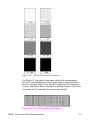
SC0,100,0,100;
Set up user scaling so that P1 is (0,0)
and P2 is (100,100) (these points are
the lower-left and upper-right corners
of the PCL Picture Frame,
respectively).
PD100,0,100,
100,0,100,0,0;
Draw a box marking the perimeter of
the PCL Picture Frame.
Default Settings 18-17
Table 18-2
Note
Example: Creating a Simple Drawing (continued)
PU50,50;CI25;
Lift the pen and move to the center of
the PCL Picture Frame (50,50); draw
a circle with a radius that is 25% of
the picture frame width.
E
C%1A
Enter the PCL mode with the cursor at
the current HP-GL/2 pen position.
E E
C
Reset the printer to end the job and
eject a page.
Any line drawn along the border of the effective window will cause the
line to be clipped, producing a line width one-half of the defined pen
width. For example, all the lines drawn in the above example are half
the width of the other lines since they are clipped at the window
borders.
18-18 The Picture Frame
EN
19
The Configuration
and Status Group
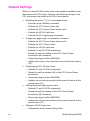
Introduction
The configuration and status group commands help you:
z
Establish default conditions and values for HP-GL/2 features.
z
Scale images in the dimensional units you want to use.
z
Enlarge/reduce images for different media sizes.
z
Establish a window (soft-clip limits).
z
Draw equal-sized and mirror-imaged drawings.
z
Rotate the HP-GL/2 coordinate system.
z
Add comments to your HP-GL/2 command sequence.
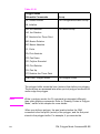
Table 19-1 lists the commands described in this chapter.
EN
Introduction 19-1
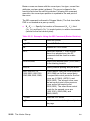
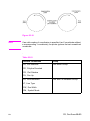
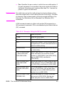
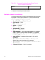
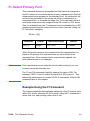
Table 19-1
The Configuration and Status Group Commands
Command
Summary
CO, Comment
Allows comments to be included in an
HP-GL/2 command sequence.
DF, Default
Sets most programmable HP-GL/2
features to their default conditions.
IN,Initialize
Sets all programmable HP-GL/2 features
to their default conditions.
IP, Input P1 and P2
Establishes new or default locations for
the scaling points P1 and P2.
IR, Input Relative P1
and P2
Establishes P1 and P2 locations as a
percentage of the PCL Picture Frame.
IW, Input Window
Sets up a window (soft-clip limits).
PG, Advance Full Page
This command is ignored.1
RO, Rotate Coordinate
System
Rotates the HP-GL/2 coordinate system.
RP, Replot
This command is ignored.
SC, Scale
Establishes a user-unit coordinate
system.
1. These commands, useful in plotter applications, are not the optimal solution for
PCL 5 printers. Other PCL commands perform similar functions (see the Number
of Copies and Form Feed command descriptions).
19-2 The Configuration and Status Group
EN
Establishing Default Conditions
Whether you are using HP-GL/2 mode or strictly the PCL printer
language mode, you should establish default conditions at the
beginning of each print job to prevent unexpected results due to
“leftover” command parameters from a previous job. From within
HP-GL/2 mode there are two ways to establish default conditions:
using the Initialize (IN) command or using the Default (DF) command.
Using the IN command sets the printer to its user-selected defaults.
This process is called initialization. The reset command (ECE)
executes an Initialize (IN) command automatically, so if a reset was
sent at the beginning of your print job, HP-GL/2 command parameters
are at their user-selected default state when HP-GL/2 mode is first
entered. (See Chapter 3 for a more thorough discussion of the printer
environment and how it is affected by the reset command.)
Note
HP-GL/2 command parameters are set to their default values the first
time HP-GL/2 mode is entered during a print job (assuming that an
E
CE reset is sent at the beginning of the job). After commands have
been sent to modify the current print environment, the command
parameters are no longer set to their defaults. When re-entering
HP-GL/2 mode, immediately sending an IN command ensures that
HP-GL/2 features are set to their default conditions (if that is desired).
The DF command is not as powerful as the IN command. The
conditions set by the DF and IN commands are described later in
this chapter.
EN
Establishing Default Conditions 19-3
The Scaling Points P1 and P2
When you scale a drawing, you define your own units of measurement, which the printer then converts to plotter units. Scaling relies
on the relationship between two points: P1 and P2. These two points
are called the scaling points because they take on the user-unit
values that you specify with the Scale (SC) command. You can
change the locations of P1 and P2 using either the Input P1 and P2
(IP), or Input Relative P1 and P2 (IR) command.
P1 and P2 always represent an absolute location in relation to the
PCL Picture Frame, defined in plotter-units. They designate opposite
corners of a rectangular printing area within the picture frame. You
can change the size of the rectangular printing area and move it
anywhere within the picture frame, or even outside the picture frame,
depending on the plotter-unit coordinates you specify using the IP or
IR commands.
Using the Scale Command
Scaling allows you to establish units of measure with which you
are familiar, or which are more logical to your drawing. The Scale
command (SC) determines the number of user-units along the Xand Y-axes between P1 and P2. The actual size of the units depends
on the locations of P1 and P2 and the range of user-units set up by
the SC command.
There are three types of scaling:
z
Anisotropic
z
Isotropic
z
Point-factor
Anisotropic scaling indicates that the size of the units along the
X-axis may be different than the size of the units on the Y-axis.
Isotropic scaling, then, indicates that the units are the same size
on both axes. Point-factor scaling sets up a ratio of plotter units to
user-units.
The Scale command does not change the locations of P1 and P2,
only their coordinate values. Also, scaling is not limited to the
rectangular area defined by P1 and P2, but extends across the
entire printing area within the PCL Picture Frame.
19-4 The Configuration and Status Group
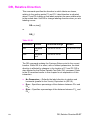
EN
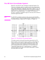
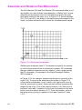
For example, to divide the X-axis into 12 units, and the Y-axis into
10 units, specify the X-axis to scale from 0 to 12, and the Y-axis to
scale from 0 to 10. P1 becomes the origin with user-unit coordinate
(0,0) and P2 becomes (12,10). The entire plotting area is now divided
into the desired units. Subsequent plotting commands use these units
(see Figure 19-1). If you command the printer to move to the point
(3,4), the printer moves to the location equivalent to (3,4) user-units
(not (3,4) plotter units).
Figure 19-1 User-Unit Scaling with Default P1 and P2
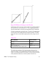
If you move the locations of P1 and P2, the size of the user-units
changes. Assume that the previous illustration showed P1 and P2
in their default locations (the lower-left and upper-right corners,
respectively, of the PCL Picture Frame). In Figure 19-2, P1 and P2
have the same user-unit values (set with the Scale command [SC]),
but their physical locations have been changed (using Input P1 and
P2 [IP]). Note that the size of the user-units decreased.
EN
Using the Scale Command 19-5
Figure 19-2 Same User-Unit Scaling with New P1 and P2
To further illustrate the flexibility of user-unit scaling, Figure 19-3
shows the P1 and P2 locations with negative user-unit values.
Note that the framework set by the scaling points P1 and P2 is not
a graphics limit. The user-unit coordinate system extends across the
entire PCL Picture Frame area. You can print to a point beyond P1 or
P2 as long as you are within the PCL Picture Frame. In Figure 19-3,
P1 is in the -X and -Y quadrant.
Note
You can use coordinate points that are outside of the PCL Picture
Frame boundaries or even off of the page, but only that portion of the
vector graphics image that falls within the effective window is printed.
For example, you can draw a small portion of the circumference of a
circle with a 5-foot radius by moving the pen 5 feet from the page and
issuing a CI command (specifying a 5-foot radius); only the portion of
the arc that falls within the effective window is printed.
19-6 The Configuration and Status Group
EN
Figure 19-3 New P1 and P2 User-Unit Scaling with
Negative Values
Refer to the Scale (SC) command at the end of this chapter for more
information on scaling drawings.
EN
Using the Scale Command 19-7
Using Scaling Effectively
The following sections describe how to combine scaling and P1/P2
concepts to do the following.
z
Enlarge or reduce the size of a drawing
z
Draw equal-size pictures on the same page.
z
Create mirror-imaged pictures
Enlarging or Reducing a Picture
The basic technique for changing a picture’s size is to scale the
printing area defined by P1 and P2, then move the locations of P1
and P2 to define a smaller or larger area. This is especially useful
when you want to print the picture on any portion of the page.
Note
Only scaled drawings (those using the SC command) are
enlarged/reduced when the P1/P2 locations change. Use PCL
Picture Frame scaling when importing HP-GL/2 images created
without the SC command (see “Automatically Adjusting the Image
Size” in Chapter 18).
To maintain the proportions of scaled plots, set P1 and P2 to define
an area with the sameaspect ratio as the original scaling rectangle.
For example, if the area defined by P1 and P2 is 3000 x 2000 plotter
units, its aspect ratio is 3:2. To enlarge the plot, set P1 and P2 to
define a larger area that maintains a 3:2 ratio.
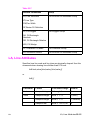
The following example illustrates this technique using a square P1/P2
scaling rectangle with a scale of 0 to 10 for both axes. By definition,
a square always has an aspect ratio of 1:1. After drawing a circle
within the scaled area, the locations of P1 and P2 move to form a
new square area that maintains the 1:1 ratio. Note that the circle
printed in the new area is smaller but is proportionately identical.
19-8 The Configuration and Status Group
EN
Table 19-2
E
EN
Example: Changing the Size of a Drawing
C%0B
Enter HP-GL/2 mode, using the default
picture frame size and anchor point.
IN;
Initialize HP-GL/2 mode.
IP0,0,2000,2000;
Set P1 to be (0,0) and P2 to be
(2000,2000).
SC0,10,0,10;
Set up user-unit scaling to range from
(0,0) to (10,10).
SP1;
Select pen number 1. Even though there
is no physical pen, the SP command
must be used to enable printing.
PA5,5;
Begin absolute plotting from the center of
the square (5,5).
CI3;
Print a circle with a radius of 3 user-units.
IP2500,500,3500,1500;
Input a new P1 and P2 position for
printing the smaller circle.
PA5,5;
Begin absolute plotting from the center of
the new square (5,5).
CI3;
Print the second circle with a radius of
3 user-units.
E
C%0A
Enter PCL Mode.
E
CE
Reset the printer to complete the job and
eject the page.
Using Scaling Effectively 19-9
Figure 19-4 Changing the size of a drawing
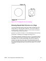
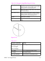
Drawing Equal-Size Pictures on a Page
You may occasionally want to print more than one drawing on the
same page for a side-by-side comparison. This can be useful for
comparing parts, assemblies, layouts, or other similar information.
The easiest way to draw equal-sized
pictures on one piece of paper is to take advantage of the fact that
P2 follows P1 whenever you change the location of P1.
The following example illustrates this feature. The example locates
P1 and P2 on the left side of the paper and scales the area for the
first image. Then, for the second image, only the P1 location is
moved to the right side of the paper; P2 automatically tracks P1,
so the printing area retains the same dimensions as the first drawing.
The printed rectangle around the second area shows P2 in its new
location.
19-10 The Configuration and Status Group
EN
Table 19-3
EN
Example: Drawing Equal-Size Pictures on a Page
E
CE
Reset the printer.
E
C&l1O
Select landscape orientation.
E
C%0B
Enter HP-GL/2 mode, using the
default picture frame size and anchor
point.
IN;
Initialize HP-GL/2 mode.
IP500,500,5450,7500;
Set P1 to be (500,500) and P2 to be
(5450,7500).
SC0,10,0,15;
Set up user-unit scaling to range from
(0,0) to (10,15).
SP1;
Select pen number 1. Even though
there is no physical pen, the SP
command must be used to enable
printing.
PA0,0;
Begin absolute plotting from the
origin (0,0).
PD10,0,10,15,0,15,0,0;PU;
Pen Down and print from (0,0) to
(10,0) to (10,15) to (0,15) to (0,0);
then Pen Up.
IP5550,500
Input a new P1 and allow P2 to
automatically track it.
PA0,0;
Begin absolute plotting from the new
origin.
PD10,0,10,15,0,15,0,0;PU;
Pen Down and print from (0,0) to
(10,0) to (10,15) to (0,15) to (0,0);
then Pen Up.
E
C%0A
Enter PCL Mode.
E
CE
Reset the printer to complete the job
and eject the page.
Using Scaling Effectively 19-11
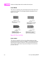
Figure 19-5 Drawing equal-size pictures on a page
Note
The P1/P2 frames are not windows or graphics limits; the pen can
print HP-GL/2 images anywhere within the PCL Picture Frame. Note
that the new P1 and P2 retain their scaled values. This allows you to
use the same coordinates on both halves of the page. In contrast, if
you do not assign a scale to P1 and P2, you must calculate the new
plotter unit coordinates for the drawing on the second half of the page.
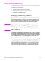
Creating Mirror-Images
For most drawings, you will probably set P1 and P2 so that P1 is in
the lower-left corner and P2 is in the upper-right corner of the scaling
area. However, you can change the relationship of P1 and P2 to
produce a mirror-image effect.
You can “mirror-image” any scaled drawing (those drawings using
the SC command) by changing the relative locations of P1 and P2,
or changing the coordinate system by using SC. You can mirrorimage labels using the Absolute Direction and Relative Direction
(DI and DR) commands, the Relative Character Size (SR) command,
or using the Absolute Character Size (SI) command. (The DI, DR,
and SR commands are discussed in Chapter 23, The Character
Group.)
19-12 The Configuration and Status Group
EN
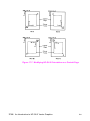
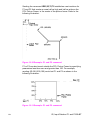
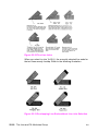
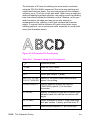
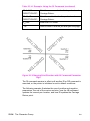
The following example uses a subroutine to draw the same picture
(an arrow) four times. Because the program changes the relative
locations of P1 and P2, the direction of the arrow is different in each
of the four drawings. The
program sets P1 and P2, draws the plot, then returns to reset P1
and P2 (using the IP command). This continues until all four possible
mirror-images are plotted. (The original drawing is shown in each
picture so you can compare the orientation of the mirror-image.)
Table 19-4
EN
Example: Creating a Mirror-Image
E
CE
Reset the printer.
E
C%0B
Enter HP-GL/2 mode.
IN;
Initialize HP-GL/2 mode.
SP1;
Select pen number 1. You must use
the SP command to enable printing.
IP1500,3600,3000,5100;
Specify the P1/P2 locations for the first
arrow figure.
SC-15,15,-10,10;
Set up user scaling: (-15,-10) to
(15,10).
(Run subroutine)
Run the subroutine (below) that prints
the arrow image.
IP3000,3600,1500,5100;
Change the physical locations of P1
and P2 to flip the image to the left.
(Run subroutine)
Print the second image.
IP1500,5100,3000,3600;
Change the physical locations of P1
and P2 to flip the image down.
(Run subroutine)
Print the third image.
IP3000,5100,1500,3600;
Change P1/P2 locations to flip the
image to the left and down.
(Run subroutine)
Print the fourth image.
E
C%0A
Enter the PCL mode.
E
CE
Send a reset to end the job and eject
the page.
Using Scaling Effectively 19-13
Table 19-4
Example: Creating a Mirror-Image (continued)
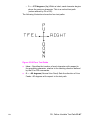
SUBROUTINE:
Subroutine that prints the arrow figure
on the next page
PA1,2;PD1,4,3,4,3,7,2,7,
4,9,6,7,5,7,5,4,12,4,12,
5,14,3,12,1,12,2,1,2; PU;
Figure 19-6 Creating a mirror-image
19-14 The Configuration and Status Group
EN
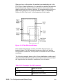
Adapting the HP-GL/2 Coordinate System to
Match the PCL System
The following example uses the IP and SC commands to change
HP-GL/2 coordinate system to match the default PCL coordinate
system. The IP command is used to invert the Y-axis so that the Y
values increase as the pen moves down the page. The SC command
equates user-units to dot positions (300 dots-per-inch). The example
draws a few lines in both PCL and HP-GL/2 modes to demonstrate
that the coordinate systems are lined up correctly (the end points of
the lines intersect).
Notes
Sending an IN (Initialize) or DF (Default) command causes the
coordinate system to revert to the HP-GL/2 default.
Since this example is based on the default top margin and text length,
changing the top margin or the text length moves the two coordinate
systems out of alignment.
Table 19-5
EN
Example: Adapting the HP-GL/2 Coordinate System
to Match the PCL System in Portrait Orientation
E
CE
Reset the printer.
E
C&l2A
Set the page size to letter.
E
C&l0O
Specify portrait orientation.
E
C&l0E
Set top margin to 0.
E
C*p0x0Y
Move to position (0,0).
E
C*c5760x7920Y
Set picture frame to 8’’ x 11’’ (size of
logical page).
E
C*c0T
Set picture frame anchor point to
current PCL cursor position (0,0).
E
C%1B
Enter HP-GL/2 mode with the HP-GL/2
cursor or pen at the PCL cursor
position.
Using Scaling Effectively 19-15
Table 19-5
Example: Adapting the HP-GL/2 Coordinate System
to Match the PCL System in Portrait Orientation
IN;SP1;
Initialize HP-GL/2 command values and
select pen number 1 (black). (The IN
command moves the pen position from
the anchor point to the HP-GL/2 origin,
the lower-left corner of the PCL Picture
Frame.)
SC0,3.3867,0,-3.3867,2
Set-up a user scale with a user-unit
equal to 1/300 inch. Scale command
type 2, the scale is the ratio of plotter
units/user-units (1016 plotter
units-per-inch/300 dots-per-inch =
3.3867). The minus 2 Y-value changes
the HP-GL/2 Y direction to match that of
the PCL coordinate system.
IR0,100,0,100
Place P1 (point 0,0) at the top of the
PCL picture frame.
PU0,0;
Lift the pen and move to (0,0) (upper left
corner — since HP-GL/2 coordinate
system now matches PCL coordinate
system). Every subsequent pen move
can be specified using the same
coordinate numbers in either mode. The
following commands demonstrate that
the grids are synchronized.
PU300,300;PD600,600;
Lift the pen and move it to (300,300);
then draw a line to (600,600). This
draws a line at a 45° angle down from
the starting point.
E
C%1A
Enter the PCL mode with HP-GL/2’s
pen position being inherited as PCL’s.
CAP=(600,600).
E
C*c300a4b0P
Draw a horizontal line (rule) that is 300
PCL units wide by 4 PCL units. (Note
that the cursor position after a rule is
printed is at the beginning of the rule —
in this case, (600,600).)
19-16 The Configuration and Status Group
EN
Table 19-5
E
Example: Adapting the HP-GL/2 Coordinate System
to Match the PCL System in Portrait Orientation
C%1BPU;PR300,0;
PD;PR0,500;
Enter HP-GL/2 mode (inheriting PCL’s
CAP) and lift the pen; move to a point
300 user-units (dots) to the right; place
the pen down and print a line 500
user-units down.
E
C%1A
Enter the PCL mode with the CAP at
the current HP-GL/2 pen position.
E
CE
Reset the printer to end the job and
eject a page.
Figure 19-7 Adapting the HP-GL/2 coordinate system to match
the PCL system in portrait orientation
EN
Using Scaling Effectively 19-17
Windowing: Setting Up Soft-Clip Limits
Soft-clip limits temporarily restrict pen movement to a rectangular
area, or window. When you initialize or set the printer to default
conditions, the soft-clip limits are the same as the PCL Picture
Frame limits.
To create a window, you use the Input Window (IW) command.
The printer does not draw outside the window.
The following illustration shows the four types of line segments you
can specify from one point to another.
Table 19-6
Type
The Four Types of Line Segments
From Last Point
To New Point
1
Inside window area
Inside window area
2
Inside window area
Outside window area
3
Outside window area
Inside window area
4
Outside window area
Outside window area
Figure 19-8 The four types of line segments
19-18 The Configuration and Status Group
EN
The IW command lets you control the size of the HP-GL/2 printing
area so that you can draw a particular portion of a drawing. You can
leave the rest as white space, or use the remaining area for labels, or
another drawing. Refer to “The Vector Graphic Limits” in Chapter 17,
and the IW command description later in this chapter.
CO, Comment
This command allows comments to be inserted within an HP-GL/2
command sequence. The comment string of the CO command must
be delimited by double quotes.
CO “text ... text”
HP-GL/2 comments are ignored by the printer.
DF, Default Values
This command returns the printer’s HP-GL/2 settings to the factory
default settings. Use the Default Values (DF) command to return the
printer to a known state while maintaining the current locations of P1
and P2 (unlike the IN command). When you use DF at the beginning
of a command sequence, graphics parameters such as character
size, slant, or scaling are defaulted.
DF [;]
The DF command resets the printer to the conditions listed in Table
19-7.
Table 19-7
EN
Default Conditions
Function
Command
Default Condition
Anchor Corner
AC
Anchor corner (not the
same as the picture frame
anchor point) set to
lower-left corner of PCL
Picture Frame, relative to
the current coordinate
system.
Alternate Font
Definition
AD
Stick Font (11.5-pt., 9-cpi,
upright, medium)
Character Fill Mode
CF
Solid fill, no edging.
CO, Comment 19-19
Table 19-7
Default Conditions (continued)
Absolute Direction
DI1,0
Character direction parallel
to X-axis.
Define Label
Terminator
DT
ETX and non-printing
mode.
Define Variable Text
Path
DV
Text printed left to right
with normal Line Feed.
Extra Space
ES
No extra space.
Fill Type
FT
Solid fill.
Input Window
IW
Set equal to PCL Picture
Frame Window.
Line Attributes
LA
Butt caps, mitered joins,
and miter limit=5.
Label Origin
LO1
Standard labeling starting
at current location.
Line Type
LT
Solid line, relative mode,
pattern length=4% of
diagonal distance from P1
to P2.
Plotting Mode
PA
Absolute plotting.
Polygon Mode
PM
Polygon buffer cleared.
Raster Fill
RF
Solid black.
Scalable or Bitmap
Fonts
SB0
Scalable fonts only.
Scale
SC
User-unit scaling off.
Screened Vectors
SV
No screening
Standard Font
Definition
SD
Stick Font (11.5-pt., 9-cpi,
upright, medium)
Absolute Character
Size
SI
Turns off size
transformation.
Character Slant
SL
No slant.
Symbol Mode
SM
Turns off symbol mode.
Select Standard Font
SS
Standard font selected.
19-20 The Configuration and Status Group
EN
Table 19-7
Default Conditions (continued)
Transparency Mode
TR1
Transparency mode on.
Transparent Data
TD
Normal printing mode.
User-Defined Line
Type
UL
Defaults all 8 line types.
In addition, the printer updates the Carriage Return point for labeling
to the current pen location. (See Chapter 23, The Character Group,
for more information on the Carriage Return point.)
The DF command does not affect the following HP-GL/2 conditions.
z
Locations of P1 and P2.
z
Current pen, its location, width, width unit selection, and up/down
z
position.
z
HP-GL/2 drawing rotation.
Table 19-8
Related commands
Related Commands
Group
IN, Initialize
The Configuration/Status Group
IN, Initialize
This command resets all programmable HP-GL/2 functions to their
default settings. Use the IN command to return the printer to a known
HP-GL/2 state and to cancel settings that may have been changed by
a previous command sequence. (The ECE Reset issues an automatic
IN command.)
IN [;]
Notes
In this manual, all command sequence examples begin with IN to
clear unwanted conditions from the previous command sequence,
even though an ECE command automatically executes an IN
command.
Once HP-GL/2 mode is entered and commands are issued, the
HP-GL/2 conditions are no longer initialized. To place HP-GL/2
into the default state, send the IN command.
EN
IN, Initialize 19-21
The IN command sets the printer to the same conditions as the DF
command, plus the following:
z
Raises the pen (PU).
z
Returns the pen location to the lower-left corner of the PCL
Picture Frame (PA0,0).
z
Cancels drawing rotation (RO).
z
Sets P1 and P2 to the lower-left and upper-right corners,
respectively, of the PCL Picture Frame (IP).
z
Sets pen width mode to metric; units are millimeters (WU).
z
Sets the pen width to 0.35 mm (PW).
z
Sets number of pens to 2 (black [1] and white [0]).
Table 19-9
Affected Commands
Group
DF, RO, IP
Configuration/Status Group
PD, PU,
Vector Group
WU, PW
Line and Fill Attributes Group
Table 19-10
Related Commands
Group
DF, Default Values
Configuration/Status Group
19-22 The Configuration and Status Group
EN
IP, Input P1 and P2
This command establishes new or default locations for the scaling
points P1 and P2. P1 and P2 are used by the Scale (SC) command
to establish user-unit scaling. You can also use IP in advanced
techniques such as printing mirror-images, enlarging/reducing
drawings, and enlarging/reducing relative character size, or changing
label direction (see the previous discussion in this chapter).
IP XP1,YP1[,XP2,YP2;] or
IP [;]
Parameter
Format
Functional Range
Default
XP1YP1[,XP2,YP2;]
integer
-230 to 230 - 1
(see below)
The default location of P1 is the lower-left corner of the PCL Picture
Frame; the default location of P2 is the upper-right corner, as shown
in Figure 19-9. (The default picture frame extends from the top margin
to the bottom margin, and from the left edge to the right edge of the
logical page.)
Figure 19-9 The Default P1/P2 Locations
EN
IP, Input P1 and P2 19-23
z
Note
No Parameters — Sets P1 and P2 to their default locations,
adjusted by any current axis rotation.
If an IP command without parameters is executed after the axes
are rotated with the RO command, P1 and P2 locations change to
reflect the rotation. If the coordinate system orientation subsequently
changes (e.g., by sending an RO command), the plotter unit position
is maintained with respect to the new orientation.
z
X,Y Coordinates — Specify the location of P1 (and, optionally,
P2) in plotter units. Specifying P2 is not required. If P2 is not
specified, P2 tracks P1 and its coordinates change so that the
X,Y distances between P2 and P1 stay the same. This tracking
process can locate P2 outside the effective window. Used
carefully, the tracking function can be useful for preparing more
than one equal-sized drawing on a page. For an example, refer to
“Drawing Equal-Sized Pictures on a Page” earlier in this chapter.
z
Neither X,Y coordinate of P1 can equal the corresponding
coordinate of P2. If either coordinate of P1 equals the corresponding coordinate of P2, the coordinate of P2 is incremented
by 1 plotter unit.
The locations of P1 and P2 interact with the following commands:
Table 19-11 Commands Affected by P1/P2
Command
Group
IW, Input Window
The Configuration/Status Group
RO, Rotate Coordinate System
SC, Scale
FT, Fill Type
The Line and Fill Attributes Group
LT, Line Type
PW, Pen Width
WU, Pen Width Unit Selection
DR, Relative Direction
The Character Group
LB, Label
SR, Relative Character Size
19-24 The Configuration and Status Group
EN
An IP command remains in effect until another IP command is
executed, an IR command is executed, or the printer is initialized.
Table 19-12
Related Commands
Group
IR, Input Relative P1 and P2
The Configuration/Status Group
IW, Input Window
RO, Rotate Coordinate System
SC, Scale
EN
IP, Input P1 and P2 19-25
IR, Input Relative P1 and P2
This command establishes new or default locations for the scaling
points P1 and P2 relative to the PCL Picture Frame size. P1 and P2
are used by the Scale (SC) command to establish user-unit scaling.
IR can also be used in advanced techniques such as printing
mirror-images, enlarging/reducing drawings, and enlarging/reducing
relative character size, or changing label (text) direction.
IR XP1,YP1,[XP2,YP2;] or
IR [;]
Parameter
Format
Functional
Range
Default
XP1YP1[XP2YP2;]
clamped real
0 to 100%
0,0,100,100%
When P1 and P2 are set using IR, the scaled area is page sizeindependent. As the PCL Picture Frame changes size, P1 and P2
keep the same relative position within the PCL Picture Frame
boundaries.
z
No Parameters — Defaults P1 and P2 to the lower-left and
upper-right corners of the PCL Picture Frame, respectively.
z
X,Y Coordinates — Specify the location of P1 (and, optionally,
P2) as percentages of the PCL Picture Frame limits (specifying
P2 is not required). If P2 is not specified, P2 tracks P1; the P2
coordinates change so that the distances of X and Y between
P1 and P2 remain the same. This tracking process can cause
P2 to locate outside the effective window. Used carefully, the
tracking function can be useful for preparing more than one
equal-sized drawing on a page. For an example, refer to
“Drawing Equal-Sized Pictures on a Page” earlier in this chapter.
z
Neither X,Y coordinate of P1 can equal the corresponding
coordinate of P2. If either coordinate of P1 equals the
corresponding coordinate of P2, the coordinate of P2 is
incremented by 1 plotter unit.
19-26 The Configuration and Status Group
EN
Sending the command IR25,25,75,75 establishes new locations for
P1 and P2 that create an area half as high and half as wide as the
PCL Picture Frame, in the center of the picture frame. Refer to the
following illustration.
Figure 19-10Example: P1 and P2 command
P1 or P2 can also be set outside the PCL Picture Frame by specifying
parameters less than zero and greater than 100. For example,
sending (IR-50,0,200,100) would set P1 and P2 as shown in the
following illustration.
Figure 19-11Example: P1 and P2 command
EN
IR, Input Relative P1 and P2 19-27
If you specify P1 and P2 beyond the PCL Picture Frame, your drawing
is scaled with respect to those locations; however, only the portion of
the drawing fitting within the effective window is drawn.
Note
The specified P1/P2 percentages are converted to the equivalent
plotter unit coordinates. If the coordinate system orientation
subsequently changes (for example, by sending an RO command),
the plotter unit position is maintained with respect to the new
orientation. If an IP command without parameters is executed after
the axes have been rotated with the RO command, P1 and P2
locations change to reflect the rotation.
The locations of P1 and P2 interact with the following commands:
Table 19-13 Commands Affected by P1/P2
Command
Group
IW, Input Window
The Configuration/Status Group
RO, Rotate Coordinate System
SC, Scale
FT, Fill Type
The Line and Fill Attributes Group
LT, Line Type
PW, Pen Width
WU, Pen Width Unit Selection
DR, Relative Direction
The Character Group
LB, Label
SR, Relative Character Size
An IR command remains in effect until another IR command is
executed, an IP command is executed, or the printer is initialized.
19-28 The Configuration and Status Group
EN
Table 19-14
Related Commands
Group
IP, Input P1 and P2
The Configuration/Status Group
IW, Input Window
RO, Rotate Coordinate System
SC, Scale
IW, Input Window
This command defines a rectangular area, or window, that
establishes soft-clip limits. Subsequent HP-GL/2 drawing is
restricted to this area. Use IW to restrict printing to a specified
area on the page.
IW XLL,YLL,XUR,YUR[;] or
IW [;]
Parameter
Format
XLL,YLL,XUR,YUR current
units
Functional Range Default
-230 to 230 - 1
PCL Picture Frame
The printer interprets the command parameters as follows.
z
No Parameters — Resets the soft-clip limits to the PCL Picture
Frame limits.
z
X,Y Coordinates — Specify the opposite, diagonal corners of
the window area, usually the lower-left (LL) and upper-right (UR)
corners. Coordinates are interpreted in the current units: as
user-units when scaling is on; as plotter units when scaling is off.
When scaling is on, subsequent changes to P1 and P2 move the
window in relation to the physical page, but keep the same user
coordinate locations. However, sending a subsequent SC command
binds the window to its equivalent plotter units. The window does not
change with any subsequent IP or IR commands.
EN
IW, Input Window 19-29
When you turn on the printer, the window is automatically set to the
PCL Picture Frame boundaries. You can define a window that extends
beyond the picture frame, however the printer cannot print vector
graphics beyond the effective window. All programmed pen motion is
restricted to this area. For more information, refer to “Windowing:
Setting Up Soft-Clip Limits” at the beginning of this chapter.
Figure 19-12The Effective Window
If the window falls entirely outside of the PCL Picture Frame, no
image is drawn. The IW command remains in effect until another
IW command is executed, or the printer is initialized or set to default
conditions.
The following example draws a label, then establishes a window and
again draws the label along with a line. Notice how the line and label
are clipped after the window is established, but not before.
Table 19-15 Example: The IW Command
E
CE
Reset the printer.
E
C%1B
Enter HP-GL/2 mode.
IN;
19-30 The Configuration and Status Group
Initialize HP-GL/2 mode.
EN
Table 19-15 Example: The IW Command (continued)
SP1;
Select pen number 1. Even though there
is no physical pen, the SP command must
be used to enable printing.
SI.2,.35;
Set Absolute Character Size to .2 x .35 cm.
PA2000,3200;
Specify absolute plotting and move to
location (2000,3200) (plotter units).
DT@,1;
Define label terminator to be the “@”
character, without printing the character.
LBTHIS IS AN EXAMPLE Print a label beginning at (2000,3200).
OF IW@;
(The label on the left is shown on two
lines —with a Carriage Return in the
middle of the text— for convenience in
this example. In an actual command
sequence, this label text should be all on
one line to print as shown in the plot at
the end of this example.)
IW3000,1300,4500,3700; Specify a soft-clip window (in plotter units).
PD2000,1700
Pen Down; print a line from the current
pen position to (2000,1700). Current pen
position at start of command is at the
letter W baseline.
LBTHIS IS AN EXAMPLE Print the same label at (2000,1700). (This
OF IW@;
label should not contain carriage returns
to print as shown in the plot for this
example.)
PU3000,1300;
Pen Up and move to position (3000,1300).
PD4500,1300,4500,3700; Pen Down and begin drawing box
indicating the soft-clip window.
PD3000,3700,3000,1300; Finish drawing the soft-clip window box
EN
PU;
Pen Up
E
C%0A
Enter PCL Mode.
E
CE
Reset the printer to end the job and eject
the page.
IW, Input Window 19-31
Figure 19-13Example: IW command
Table 19-16
Related Commands
Group
IP, Input P1 and P2
The Configuration/Status Group
IR, Input Relative P1 and P2
RO, Rotate Coordinate System
SC, Scale
19-32 The Configuration and Status Group
EN
PG, Advance Full Page
This HP-GL/2 command is ignored by the printer since it could
cause undesirable results when importing plots. A page eject can
be accomplished only from the PCL printer language mode.
The following PCL commands cause a conditional page eject,
meaning that a page is ejected if there is any printable data in the
print buffer:
z
E E
C
z
UEL (Universal Exit Language)
z
Flush All Pages
z
Page Length
z
Page Size
z
Orientation
z
Paper Source
Reset
When a page is ejected using one of the above commands, the PCL
cursor position is set to the top of form on the new page. (The Top of
Form is 3/4 of a line below the top margin.)
An alternative method of ejecting a page from PCL is the Form Feed
control code. A Form Feed causes an unconditional page eject and
advances the current active cursor position to the top of form on the
next page. The horizontal cursor position remains the same as before
the page eject.
Note
EN
The HP-GL/2 pen position is not affected by a Form Feed; it occupies
the same position on the next page.
PG, Advance Full Page 19-33
RO, Rotate Coordinate System
This command rotates the printer’s coordinate system relative to the
default HP-GL/2 coordinate system, in the following increments of
rotation: 90°, 180°, and 270°. Use RO to orient your drawing vertically
or horizontally, or to reverse the orientation.
RO angle[;] or
RO [;]
Parameter
Format
Functional Range
Default
angle
clamped integer
0°, 90°, 180°, or 270°
0°
The printer interprets the command parameters as follows:
z
No Parameter — Defaults the orientation of the coordinate
system to 0°. Equivalent to (RO0). This is the same as PCL’s
current orientation.
z
Angle — Specifies the degree of rotation:
0 Sets the orientation to PCL’s current orientation.
90 Rotates and shifts the coordinate system 90 degrees in a
positive angle of rotation from PCL’s current orientation.
180 Rotates and shifts the coordinate system 180 degrees in a
positive angle of rotation from PCL’s current orientation.
270 Rotates and shifts the coordinate system 270 degrees in a
positive angle of rotation from PCL’s current orientation.
Angle of Rotation
Note
A positive angle of rotation is in the direction of the +X-axis to the
+Y-axis as shown below. (A negative angle of rotation is not allowed in
the RO command.)
19-34 The Configuration and Status Group
EN
Figure 19-14Angle of rotations
Note
The relationship of the X-axis to Y-axis can change as a result of the
scaling point or scaling factor changes, thus changing the direction of
a positive angle of rotation.
The physical location of the pen does not change when you rotate
the coordinate system. The printer updates the pen’s X,Y coordinate
location to reflect the new orientation.
The scaling points P1 and P2 rotate with the coordinate system.
However, they maintain the same X,Y coordinate values as before
the rotation. This means that P1 and P2 can be located outside of
the PCL Picture Frame. Follow the (RO90) or (RO270) commands
with (IP) or (IR) to relocate points P1 and P2 to the lower-left and
upper-right corners of the picture frame.
When the RO command is used, the soft-clip window, if defined, is
also rotated, and any portion that is rotated outside of the picture
frame is clipped to the picture frame boundaries. The soft-clip window
can be set equal to the picture frame by issuing an “IW;” command
(see Figure 19-17).
EN
RO, Rotate Coordinate System 19-35
Note
The RO command also rotates the contents of the polygon buffer.
The RO command remains in effect until the rotation is changed by
another RO command, or the printer is initialized.
Figure 19-15 shows the default orientation and the result of rotating
the orientation without relocating P1 and P2.
Figure 19-15Using the RO Command Without Using the IP
Command
19-36 The Configuration and Status Group
EN
Figure 19-16 shows the locations of P1 and P2 when you follow the
rotation with the IP command.
Figure 19-16Using IP after the RO Command
When you set-up a soft-clip window (see the IW command), RO
also rotates the window. If a portion of a window rotates outside the
hard-clip limits, it is clipped. Note that IP does not affect the window
limits. Use IW to reset the window to the size of the PCL Picture
Frame.
EN
RO, Rotate Coordinate System 19-37
Figure 19-17Using IP and IW after the RO Command
Table 19-17
Related Commands
Group
IP, Input P1 and P2
The Configuration/Status Group
IR, Input Relative P1 and P2
IW, Input Window
19-38 The Configuration and Status Group
EN
RP, Replot
This command is ignored by the printer; to eject a page, the printer
must be in PCL printer language mode. The following commands
cause a conditional page eject; a page is ejected if there is any
printable data in the print buffer:
z
E
CE
z
UEL (Universal Exit Language)
z
Flush All Pages
z
Page Length
z
Page Size
z
Orientation
z
Paper Source
Reset
The PCL Form Feed control code causes an unconditional page eject
and advances the cursor position to the top of form on the next page.
Note
A page eject caused by any of the above commands except Paper
Source defaults the HP-GL/2 pen position.
To print more than one plot, use the Number of Copies command.
For information about printing more than one copy of an HP-GL/2
illustration, see “Number of Copies Command” in Chapter 4.
EN
RP, Replot 19-39
SC, Scale
This command establishes a user-unit coordinate system by mapping
user-defined coordinate values onto the scaling points P1 and P2.
SC XMIN,XMAX,YMIN,YMAX [,type[,left,bottom;]] or
SC XMIN,XFACTOR,YMIN,YFACTOR,type[;] or
SC [;]
Parameter
Format
Functional Range Default
XMIN,X MAX,
real
-230 to 230 - 1
no default
YMIN,Y MAX
real
-230 to 230 - 1
no default
type
clamped
integer
0, 1, or 2
0
left
clamped
real
0 to 100%
50%
bottom
clamped
real
0 to 100%
50%
XFACTOR, YFACTOR
real
-230 to 230 - 1
no default
For more information about the basic concept of scaling, refer to “The
Scale Command” earlier in this chapter.
19-40 The Configuration and Status Group
EN
There are three forms of scaling: anisotropic, isotropic, and
point-factor. The Type parameter tells the printer which form you are
using. Refer to the following table.
Table 19-18
Scaling Form
Type
Description
Anisotropic
0
Establishes standard user-unit
scaling allowing different unit size
on X-axis and Y-axis.
Isotropic
1
Establishes standard user-unit
scaling with same unit size on X-axis
and Y-axis.
Point Factor
2
Establishes P1 user-unit location
and a specific ratio of plotter units
to user-units.
z
No Parameters — Turns off scaling; subsequent coordinates are
in plotter units.
For Scaling Types 0 and 1:
The following forms of scaling establish a user-unit coordinate system
by mapping user-defined coordinate values onto the scaling points P1
and P2. The type parameter selects between anisotropic (Type 0) and
isotropic scaling (Type 1).
Table 19-19
Scaling
Form
EN
Type Syntax
Anisotropic
0
SCXMIN,XMAX,YMIN,YMAX[,type;]
Isotropic
1
SC%%XMIN,XMAX,YMIN,YMAX[,type[,left,bottom];]
SC, Scale 19-41
z
Note
XMIN, XMAX, YMIN, YMAX — These parameters represent the
user-unit X- and Y-axis ranges, respectively. For example,
SC0,15,0,10 indicates 15 user-units along the X-axis and
10 user-units along the Y-axis. As a result, the first and third
parameters (XMIN and YMIN) are the coordinate pair that is
mapped onto P1; the second and fourth parameters (XMAX
and YMAX) are the coordinate pair mapped onto P2. Using the
same example, the coordinate location of P1 is (0,0) and P2
is (15,10). This is different from the IP command, where the
parameters are expressed as X,Y coordinate pairs rather than
as ranges.
XMIN cannot be set equal to XMAX, and YMIN cannot be set equal
to YMAX.
As their names suggest, you will normally want to specify XMIN
smaller than XMAX, and YMIN smaller than YMAX. If you specify XMIN
larger than XMAX and YMIN larger than YMAX, your illustration is drawn
as a mirror-image, reversed and/or upside down, depending on the
relative positions of P1 and P2.
The parameters of the SC command are always mapped onto the
current P1 and P2 locations. P1 and P2 retain these new values until
scaling is turned off or another SC command redefines the user-unit
values. Thus, the size of a user unit could change if any change is
made in the relative position and distance between P1 and P2 after
an SC command is executed.
z
Type — Specifies anisotropic or isotropic scaling.
Table 19-20
0
Anisotropic scaling. Allows a user-unit along the
X-axis to be a different size than user-units along the
Y-axis. Printed shapes are distorted when you use
anisotropic scaling. For example, a circle might be
drawn as an ellipse—oval-shaped instead of round.
(Left and bottom parameters are ignored for
anisotropic scaling.
1
Isotropic scaling. Produces user-units that are the
same size on both the X- and Y-axes. The following
illustrations show how the printer adjusts the location
of (XMIN,YMIN) and (XMAX,YMAX) to create the
largest possible isotropic area within the P1/P2 limits.
(Remember, the user-units are always square
regardless of the shape of the isotropic area.)
19-42 The Configuration and Status Group
EN
Figure 19-18Isotropic Scaling
z
Left, Bottom — Positions the isotropic area in the P1/P2 limits.
(These parameters are always specified together and are valid for
isotropic scaling only.) The left parameter indicates the
percentage of the unused space on the left of the isotropic area;
the bottom parameter indicates the percentage of unused space
below.
• The defaults for the left and bottom parameters are each 50%.
This centers the isotropic area on the page with the unused
space equally divided between left and right or top and bottom,
as shown in the previous illustrations.
EN
SC, Scale 19-43
• Although you must specify both parameters, the printer
applies only one: the left parameter applies when there is extra
horizontal space; the bottom parameter applies when there is
extra vertical space. The following examples illustrate left and
bottom parameters of 0% and 100%.
Figure 19-19The Left and Bottom Parameters
For Scaling Type 2:
The third form of scaling, point-factor scaling, sets a specific ratio
of plotter units to user-units, and establishes the user-units coordinate
of P1.
Table 19-21
Scaling Form
Type
Syntax
Point Factor
2
SCXMIN,XFACTOR,YMIN,YFACTOR,type[;]
19-44 The Configuration and Status Group
EN
z
XMIN,XFACTOR,YMIN,YFACTOR — Establish the user-unit coordinates of P1 and the ratio of plotter to user-units. XMIN and YMIN
are the user-unit coordinates of P1. XFACTOR sets the number of
plotter units per user-unit on the X-axis; YFACTOR sets the number
of plotter units per user-unit on the Y-axis.
z
Type — Must be 2 for this type of scaling.
An SC command remains in effect until another SC command is
executed, or the printer is initialized or set to default conditions.
Examples: The following examples explain the effect of several
parameter selections.
(SC0,40,0,40,2) allows scaling in millimeters since 1 millimeter = 40
plotter units. Each user-unit is 1 millimeter.
(SC0,1.016,0,1.016,2) allows scaling in thousandths of an inch since
1 inch = 1016 plotter units.
While scaling is on (after any form of the SC command has been
executed), only those HP-GL/2 commands that can be issued in
‘current units’ are interpreted as user-units; the commands that can
be issued only in plotter units are still interpreted as plotter units.
(The command syntax discussion pertaining to each command
tells you which kind of units each parameter requires.)
The SC parameters are mapped onto the current locations of P1
and P2. P1 and P2 do not represent a graphic limit; therefore, the
new user-unit coordinate system extends across the entire range
of the plotter-unit coordinate system. Thus, you can print to a point
beyond P1 or P2, as long as you are within the effective window. For
example, you can print from the point (-1,3.5) to the point (5.5,1.5) as
shown in the following illustration.
EN
SC, Scale 19-45
Figure 19-20Example: Printing point-to-point
Table 19-22
Related Commands
Group
IP, Input P1 and P2
The Configuration/Status Group
IR, Input Relative P1 and P2
IW, Input Window
Table 19-23 Possible Error Conditions for SC
Condition
Printer Response
no parameters
turns scaling off
more than 7 parameters
executes first 7 parameters
for types 0 or 1: 6 parameters or
less than 4 parameters
ignores command
for type 2: any more or less than
5 parameters
ignores command
XMIN=XMAX or YMIN=YMAXor
number out of range
ignores command
XFACTOR=0 or YFACTOR=0
ignores command
19-46 The Configuration and Status Group
EN
20
The Vector Group
Introduction
The information in this chapter enables you to achieve the
following results in your programs:
z
Use absolute and relative coordinates when plotting.
z
Draw lines, arcs, bezier curves, and circles.
z
Encode coordinates to increase your printer’s throughput.
The following commands are described in this chapter.
Table 20-1
EN
The Vector Group Commands
Command
Summary
AA, Arc Absolute
Draws an arc using absolute
coordinates.
AR, Arc Relative
Draws an arc using relative
coordinates.
AT, Absolute Arc Three Point
Draws an arc from the current
pen location through two
absolute points.
BR, Bezier Relative
Draws a bezier curve using
relative coordinates as control
points.
BZ, Bezier Absolute
Draws a bezier curve using
absolute coordinates as
control points.
CI, Circle
Draws a circle with a specified
radius.
Introduction 20-1
Table 20-1
The Vector Group Commands (continued)
PA, Plot Absolute
Enables movement to
absolute coordinate locations
(with respect to the origin
[0,0]).
PD, Pen Down
Lowers the "pen" to the page.
PE, Polyline Encoded
Increases throughput by
encrypting common HP-GL/2
commands.
PR, Plot Relative
Enables movement relative to
the current pen location.
PU, Pen Up
Lifts the pen from the page.
RT, Relative Arc Three Point
Draws an arc from the current
pen location through two
relative points.
Drawing Lines
You can draw lines between two points (X,Y coordinate pairs) using
the PD (Pen Down) command and a series of absolute and/or relative
coordinate pairs. The printer draws only the portion of the line that
falls within the effective window.
Note
When using HP-GL/2 to draw lines, you can increase your printer’s
throughput by using the Polyline Encoded (PE) command to send
coordinates. The PE command requires that you convert coordinates
from decimal to base 64 or 32. This conversion especially increases
throughput when using a serial interface. The PE command, with its
parameters, is used in place of the PA, PD, PR, and PU commands.
20-2 The Vector Group
EN
In the following example, note that the PA (Plot Absolute) command
specifies absolute plotting, and the coordinate pair (0,0) sets the
beginning pen location.
Table 20-2
Example: Drawing Lines
E
CE
Reset the printer.
E
C%ØB
Enter HP-GL/2 mode.
IN;
Initialize HP-GL/2 mode.
SP1;
Select pen number 1 (black). You must
use the SP command to be able to print
HP-GL/2 images.
PA0,0;
Begin absolute plotting from coordinate (0,0).
PD2500,0,0,1500,0,0; Specify Pen Down and draw lines between
the points.
E
C%ØA
Enter the PCL mode.
E
CE
Send a reset to end the job and eject the
page.
Figure 20-1 Drawing lines
EN
Drawing Lines 20-3
Note
Any line drawn along the border of the effective window causes the
line to be clipped, producing a line width of one-half of what it should
be. For example, in the above plot, the lines from (0,0) to (0,1500),
and (0,0) to (2500,0) is clipped.
Drawing Circles
The Circle (CI) command uses your current pen position as the center
of the circle; you specify the radius of the circle.
The following example shows a simple command sequence using CI
to draw a circle with a radius of 500 plotter units.
Table 20-3
Example: Drawing Circles
E
CE
Reset the printer.
E
C%ØB
Enter HP-GL/2 mode.
IN;
Initialize HP-GL/2.
SP1;
Select pen number 1. The SP command must
be used to enable printing.
PA2400,2500;
Specify absolute plotting and move to position
(2400,2500).
CI500;
Draw a circle with a radius of 500 plu (plotter
units); the center of the circle is the current pen
location (2400,2500).
E
C%ØA
Enter the PCL mode.
E
CE
Send a reset to end the job and eject the page.
20-4 The Vector Group
EN
Figure 20-2 Drawing circles
Drawing Arcs
The Arc Absolute (AA) and Arc Relative (AR) commands use the
following method for drawing arcs. Your current pen location becomes
one end of the arc; you specify the center point with one parameter
(setting the radius), and set another parameter to specify the number
of degrees through which you want the arc drawn.
The following illustration shows a simple command sequence using
the AA command to draw a circle and an arc:
Table 20-4
EN
Example: Drawing Arcs
E
CE
Reset the printer.
E
C%ØB
Enter HP-GL/2 mode.
IN;
Initialize HP-GL/2.
SP1;
Select pen number 1. Even though there is no
physical pen, the SP command must be used
to enable printing.
PA4200,2900;PD;
Set starting point to (4200,2900) and set pen
down.
Drawing Arcs 20-5
Table 20-4
Example: Drawing Arcs
AA4600,2500,-180; Using the Arc Absolute command, specify the
pivot point of the arc, thereby setting the radius;
draw the arc for 180° in a negative angle of
rotation.
E
C%ØA
Enter the PCL mode.
E
CE
Send a reset to end the job and eject the page.
Figure 20-3 Drawing arcs (1 of 3)
20-6 The Vector Group
EN
Angle of Rotation
NoteS
A positive angle of rotation is in the direction of the +X-axis to the
+Y-axis as shown below.
A negative angle of rotation is in the direction of the +X-axis to the
−Y-axis.
Figure 20-4 Drawing arcs (2 of 3)
Note
The relationship of the +X-axis to +Y-axis (and -Y-axis) can change as
a result of the scaling point or scaling factor changes, thus, changing
the direction of a positive (or negative) angle of rotation.
You can also draw arcs using the Absolute Arc Three Point (AT) and
Relative Arc Three Point (RT) commands. These commands use
three known points (your current pen location plus two points you
specify) to calculate a circle and draw the appropriate arc segment
of its circumference. The arc is drawn with a positive angle of rotation,
so that it passes through the intermediate point before the end point.
Refer to the following illustration.
EN
Drawing Arcs 20-7
Figure 20-5 Drawing arcs (3 of 3)
Drawing Bezier Curves
The Bezier Absolute (BZ) and Bezier Relative (BR) commands use
your current pen position as the first control point in the Bezier curve.
You specify the second, third, and fourth control points. If you are
drawing more than one curve, the fourth control point of the first curve
(X3, Y3) becomes the first control point of the next curve.
The following example shows a simple command sequence using
BZ to draw a Bezier Curve in the shape of a sine wave (shown in the
figure following the example).
Table 20-5
Example: Drawing Bezier Curves
E
CE
Reset the printer.
E
C%ØB
Enter HP-GL/2 mode.
IN;
Initialize HP-GL/2.
SP1;
Select pen number 1. The SP command
must be used to enable printing.
PA1000,5000;PD;
Specify absolute plotting and move to
position (1000,5000); pen down.
BZ2000,8000,
4000,2000,5000,5000;
Draw a Bezier curve with (1000,5000) as
the starting point (first control point).
Specify (2000,8000), (4000,2000), and
(5000,5000) as the second, third, and
fourth control points.
E
Enter the PCL mode.
C%ØA
20-8 The Vector Group
EN
Table 20-5
E
Example: Drawing Bezier Curves (continued)
CE
Send a reset to end the job and eject the
page.
Figure 20-6 Bezier Curves
AA, Arc Absolute
This command draws an arc, using absolute coordinates, which starts
at the current pen location and pivots around the specified center
point.
AA Xcenter,Ycenter,sweep angle[,chord angle;]
Parameter
Format
Functional Range
Default
Xcenter,Ycenter current units
-230 to 230 - 1
no default
sweep angle
clamped real
-32768 to 32767
no default
chord angle
clamped real
0.5° to 180°
5°
The AA command draws an arc starting at the current pen location
using the current pen up/down status and line type and attributes.
After drawing the arc, the pen location remains at the end of the arc.
EN
AA, Arc Absolute 20-9
Note
Do not use an adaptive line type when drawing arcs with small chord
angles. The printer attempts to draw the complete pattern in every
chord (there are 72 chords in a circle using the default chord angle).
z
XCenter, YCenter — Specify the absolute location of the center
of the arc. (The center of the arc is the center of the circle that
would be drawn if the arc was 360 degrees.)
z
Coordinates are interpreted in current units: as user-units when
scaling is on; as plotter units when scaling is off. If current scaling
is not isotropic, the arc drawn is elliptical rather than circular.
z
Sweep Angle — Specifies in degrees the angle through which
the arc is drawn. A positive angle is drawn in a positive direction
(angle of rotation); a negative angle is drawn in the negative
direction.
z
Chord Angle — Specifies the chord angle used to draw the arc.
The default is a chord angle of 5 degrees. The chord angle
specifies, in degrees, the maximum angle created when lines
from each end of the chord intersect the center point of the circle
(see drawing below). The smaller the chord angle, the smoother
the curve.
Figure 20-7 Chord Angle
20-10 The Vector Group
EN
For a specific chord angle, a circle or arc always has the same
number of chords, regardless of its size. For example, for the
default chord angle, a circle is always composed of 72 chords
(360°/5° per chord = 72 chords). This results in larger circles
appearing less smooth than smaller circles with the same chord
angle; setting the chord angle to a smaller number will help large
circles or arcs appear more smooth (see Figure 20-8).
z
Figure 20-8 Changing Arc Smoothness with the Chord Angle
Table 20-6
EN
Example: Varying the Chord Angle
E
CE
Reset the printer.
E
C%ØB
Enter HP-GL/2 mode.
IN;
Initialize HP-GL/2 mode.
SP1;
Select pen number 1. Even though there is no
physical pen, the SP command must be used to
enable printing.
PA2000,0;
Specify (2000,0) as the starting point.
PD;AA0,0,45,25;
With the pen down, draw a 45° arc (positive
angle) with center coordinates of (0,0) and a
chord angle of 25°.
PU1050,1060;
Lift the pen and move to (1050,1060).
PD;AA0,0,-45,10;
With the pen down, draw a 45° arc (negative
angle) using the same center point as the first
arc, but with a 10° chord angle.
AA, Arc Absolute 20-11
Table 20-6
Example: Varying the Chord Angle (continued)
PU1000,0;
Lift the pen and move to (1000,0).
PD;AA0,0,45;
With the pen down, draw another 45° arc
(positive angle) with the same center point,
but with the default chord angle (5°).
E
C%ØA
Enter the PCL mode.
E
CE
Send a reset to end the job and eject the page.
Figure 20-9
Table 20-7
Related Commands
Group
AT, Absolute Arc Three Point
The Vector Group
BR, Bezier Relative
BZ, Bezier Absolute
AR, Arc Relative
CI, Circle
RT, Relative Arc Three Point
20-12 The Vector Group
EN
Table 20-7
LA, Line Attributes
The Line and Fill Attributes Group
LT, Line Type
PW, Pen Width
AR, Arc Relative
This command draws an arc, using relative coordinates, which starts
at the current pen location and pivots around the specified center
point.
AR Xincrement,Yincrement,sweep angle[,chord angle;]
Parameter
Format
Functional Range
Default
Xincrement,Yincrement current
units
-230 to 230 - 1
no default
sweep angle
clamped
real
-32768 to 32767
no default
chord angle
clamped
real
0.5° to 180°
5°
The AR command draws the arc starting at the current pen location
using the current pen up/down status, line type, and attributes. After
drawing the arc, the pen location remains at the end of the arc.
Note
Do not use an adaptive line type when drawing arcs with small chord
angles. The printer attempts to draw the complete pattern in every
chord (there are 72 chords in a circle using the default chord angle).
z
XIncrement, YIncrement — Specify the center of the arc relative to
the current location. (The center of the arc is the center of the
circle that would be drawn if the arc was 360 degrees.)
Coordinates are interpreted in current units: as user-units when
scaling is on; as plotter units when scaling is off. If current scaling
is not isotropic, the arc drawn is elliptical rather than circular.
EN
AR, Arc Relative 20-13
z
Sweep Angle — Specifies (in degrees) the angle through which
the arc is drawn. A positive angle draws an angle in the positive
direction (angle of rotation); a negative angle draws the angle in
the negative direction.
z
Chord Angle — Specifies the chord angle used to draw the arc.
The default is a chord angle of 5 degrees. Refer to the Arc
Absolute (AA) command discussion (earlier this chapter) for
information on setting and determining the chord angle.
Table 20-8
Example: Using Arc Relative to Draw Arcs
E
CE
Reset the printer.
E
C%ØB
Enter HP-GL/2 mode.
IN;
Initialize HP-GL/2 mode.
SP1;
Select pen number 1. Even though there is no
physical pen, the SP command must be used
to enable printing.
PA1500,1500;PD;
Specify the starting position as (1500,1500)
and put the pen down.
AR0,2000,80,25;
Draw an arc with a center point 0 plu in the X
direction and 2000 plu in the Y direction from
(1500,1500). Specify the arc section to be 80°
(positive angle), with a chord angle of 25°
AR2000,0,80;
Draw an arc with a center point 2000 plu in the
X direction and 0 plu in the Y direction from the
current pen position. Specify the arc section to
be 80° (positive angle), with a default chord
angle (5°).
E
C%ØA
Enter the PCL mode.
E
CE
Send a reset to end the job and eject the page.
20-14 The Vector Group
EN
Figure 20-10
Table 20-9
Related Commands
Group
AA, Arc Absolute
The Vector Group
AT, Absolute Arc Three Point
BR, Bezier Relative
BZ, Bezier Absolute
CI, Circle
RT, Relative Arc Three Point
LA, Line Attributes
The Line and Fill Attributes Group
LT, Line Type
PW, Pen Width
EN
AR, Arc Relative 20-15
AT, Absolute Arc Three Point
This command draws an arc segment, using absolute coordinates,
from a starting point, through an intermediate point, to an end point.
Use AT when you know these three points of an arc.
AT Xinter,Yinter, Xend,Yend[,chord angle;]
Parameter
Format
Functional Range
Default
Xinter, Yinter
current units
-230 to 230 - 1
no default
Xend, Yend
current units
-230 to 230 - 1
no default
chord angle
clamped real
0.5° to 180°
5°
The AT command uses the current pen location and two specified
points to calculate a circle and draw the appropriate arc segment of
its circumference. The arc starts at the current pen location, using the
current pen, line type, line attributes and pen up/down status. You
specify the intermediate and end points. After drawing the arc, the
pen location remains at the end of the arc.
z
XInter,YInter — Specify the absolute location of an intermediate
point of the arc. The arc is drawn in a positive or negative angle
of rotation, as necessary, so that it passes through the intermediate point before the end point.
z
XEnd,YEnd — Specify the absolute location of the end point of
the arc.
z
Chord Angle — Specifies the chord angle used to draw the
arc. The default is a chord angle of 5°. (The Arc Absolute (AA)
command description [earlier in this chapter] contains more
information on chords and chord angles.)
Intermediate and end point coordinates are interpreted in current
units: as user-units when scaling is on; as plotter units when scaling
is off. If current scaling is not isotropic, the arc drawn is elliptical rather
than circular. Note the following about locating the intermediate and
end points:
z
If the intermediate point and end point are the same as the
current pen location, the command draws a dot.
z
If the intermediate point is the same as either the current pen
location or the end point, a line is drawn between the current
pen location and the end point.
20-16 The Vector Group
EN
z
If the end point is the same as the current pen location, a circle
is drawn, with its diameter being the line from the current pen
position to the intermediate point.
z
If the current pen position, intermediate point, and end point are
collinear, a straight line is drawn.
z
If the intermediate point does not lie between the current pen
location and the end point, and the three points are collinear,
two lines are drawn; one from the current pen location and the
other from the end point, leaving a gap between them. Refer to
the following illustration. Both lines extend to the PCL Picture
Frame limits or current window.
Figure 20-11
Table 20-10 Example: Using the AT Command
EN
E
CE
Reset the printer.
E
C%ØB
Enter HP-GL/2 mode.
IN;
Initialize HP-GL/2 mode.
SP1;
Select pen number 1 (black).
PA1000,100;
PD2500,100;
Specify (1000,100) as the starting
location, place the pen down, and
draw a line to (2500,100).
PU650,1150;
PD1000,1150;
Lift the pen, move to (650,1150),
place the pen down, and draw a line
to (1000,1150).
AT, Absolute Arc Three Point 20-17
Table 20-10 Example: Using the AT Command (continued)
PU650,450; PD1000,450;
Lift the pen, move to (650,450), place
the pen down, and draw a line to
(1000,450).
PU1000,100;
PD1000,1500, 2500,1500;
Lift the pen, move to (1000,100),
place the pen down, draw a line to
(1000,1500), then to (2500,1500).
AT3200,800,2500,100;
Print an arc, starting at current pen
position (2500,1500), passing
through (3200,800) and ending at
(2500,100).
PU3200,900;PD;
Lift the pen, move to (3200,900) and
set the pen down.
AT3300,800,3200,700;
Print an arc, starting at the current
pen position, passing through
(3300,800) and ending at (3200,700).
PU3300,800; PD3500,800;
Lift the pen, move to (3300,800), pen
down, and draw a line to (3500,800).
E
C%ØA
Enter the PCL mode.
E
CE
Send a reset to end the job and eject
the page.
Figure 20-12
20-18 The Vector Group
EN
Table 20-11
Related Commands
Group
AA, Arc Absolute
The Vector Group
AR, Arc Relative
BR, Bezier Relative
BZ, Bezier Absolute
CI, Circle
RT, Relative Arc Three Point
LA, Line Attributes
The Line and Fill Attributes Group
LT, Line Type
PW,Pen Width
BR, Bezier Relative
This command draws bezier curves using relative coordinates. This
command uses the current pen position as the first control point, and
specifies the other three control points as relative increments from the
first point.
BR X1,Y1, X2,Y2,X3,Y3,...[X1,Y1, X2,Y2,X3,Y3]]
Parameter
Format
X1, Y1... (control points) current
units
Functional Range Default
-223 to 223 - 1
no default
The BR command uses the current pen location and three specified
control points to draw a bezier curve. After each new Bezier, the last
control point of the previous curve becomes the first control point of
the next Bezier. All curve control points are relative to the first control
point of that curve. For example, points 1, 2, and 3 of the example are
relative to the starting point, while points 4, 5, and 6 are relative to
point 3.
EN
BR, Bezier Relative 20-19
Bezier curves are drawn with the current pen, line type, current line
attributes, and pen-state (up/down). The curve is clipped to the
hard-clip limits and the soft-clip window. Following the command
execution, the current pen position is updated to the end point of
the curve.
The BR command is allowed in Polygon Mode. (The first chord after
PM1 is not treated as a pen-up move.)
X1, Y1... — Specify the location of the second (X1, Y1), third
(X2, Y2), and fourth (X3, Y3) control points, in relative increments
(relative to the first control point).
z
Table 20-12 Example: Using the BR Command (Bezier Relative)
E
CE
Reset the printer.
E
C%ØB
Enter HP-GL/2 mode.
IN;
Initialize HP-GL/2 mode.
SP1;
Select pen number 1. Even though
there is no physical pen, the SP
command must be used to enable
printing.
PA1016,5080;
Specify the absolute point (1016,5080)
as the starting location.
PR;PD;
Specify relative plotting and pen down.
BR0,3048,4572,0,
3556,2032,-508,1016,
2540,508,2540,-5080;
Draw a Bezier using the current position
(1016,5080) as the first control point.
The specified control points for the first
curve are (0,3048), (4572,0), and
(3556,2032). The second curve uses
the last control point of the previous
curve as the first control point
(3556,2032). The other three control
points for the second curve are
(-508,1016), (2540,508), and
(2540,-5080).
E
C%ØA
Enter the PCL mode.
E
CE
Send a reset to end the job and eject
the page.
20-20 The Vector Group
EN
Figure 20-13
Table 20-13
Related Commands
Group
AA, Arc Absolute
The Vector Group
BZ, Bezier Absolute
AR, Arc Relative
AT, Absolute Arc Three Point
CI, Circle
RT, Relative Arc Three Point
LA, Line Attributes
The Line and Fill Attributes Group
LT, Line Type
PW, Pen Width
EN
BR, Bezier Relative 20-21
BZ, Bezier Absolute
This command draws bezier curves using absolute coordinates. The
BZ command uses the current pen position as the first control point,
and specifies the other three control points as absolute coordinates.
BZ X1,Y1, X2,Y2,X3,Y3,...[X1,Y1, X2,Y2,X3,Y3]]
Parameter
Format
X1, Y1... (control points) current
units
Functional Range
Default
-223 to 223 - 1
no default
The BZ command uses the current pen location and three specified
control points to draw a bezier curve. After each new Bezier, the last
control point of the previous curve becomes the first control point of
the next Bezier. All curve control points are specified as absolute
coordinates.
Bezier curves are drawn with the current pen, line type, current line
attributes, and pen-state (up/down). The curve is clipped to the
hard-clip limits and the soft-clip window. Following the command
execution, the current pen position is updated to the end point of
the curve.
The BZ command is allowed in Polygon Mode. (The first chord after
PM1 is not treated as a pen-up move.)
X1, Y1... — Specify the location of the second (X1, Y1), third (X2,
Y2), and fourth (X3, Y3) control points, as absolute coordinates.
z
Table 20-14 Example: Using the BZ Command (Bezier Absolute)
E
CE
Reset the printer.
E
C%ØB
Enter HP-GL/2 mode.
IN;
Initialize HP-GL/2 mode.
SP1;
Select pen number 1. Even though
there is no physical pen, the SP
command must be used to enable
printing.
20-22 The Vector Group
EN
Table 20-14 Example: Using the BZ Command (Bezier Absolute)
PA1016,5080;
Specify the absolute point
(1016,5080) as the starting location.
PR;PD;
Specify relative plotting and pen
down.
BZ1016,8128,5588,5080,
4572,7112,4064,8128,
EN
7112,7620,7112,2032;
Draw a Bezier using the current
position (1016,5080) as the first
control point. The specified control
points for the first curve are
(1016,8128), (5588,5080), and
(4572,7112). The second curve uses
the last control point of the previous
curve as the first control point
(4572,7112). The other three control
points for the second curve are
(4064,8128), (7112,7620), and
(7112,2032).
E
C%ØA
Enter the PCL mode.
E
CE
Send a reset to end the job and eject
the page.
BZ, Bezier Absolute 20-23
Figure 20-14
Table 20-15
Related Commands
Group
AA, Arc Absolute
The Vector Group
BR, Bezier Relative
AR, Arc Relative
AT, Absolute Arc Three Point
CI, Circle
RT, Relative Arc Three Point
LA, Line Attributes
The Line and Fill Attributes Group
LT, Line Type
PW, Pen Width
20-24 The Vector Group
EN
CI, Circle
This command draws the circumference of a circle using the specified
radius and chord angle. If you want a filled circle, refer to the WG or
PM commands.
CI radius[,chord angle;]
Parameter
Format
Functional Range
Default
radius
current units
-230 to 230 - 1
no default
chord angle
clamped real
0.5° to 180°
5°
The CI command includes an automatic pen down. When a CI
command is received, the pen lifts, moves from the center of the
circle (the current pen location) to the starting point on the
circumference, lowers the pen, draws the circle, then returns
with the pen up to the center of the circle. After the circle is drawn,
the previous pen up/down status is restored. To avoid leaving a dot
at the center of the circle, move to and from the circle’s center with
the pen up.
z
Radius — Measured from the current pen location. Coordinates
are interpreted in current units: as user-units when scaling is on;
as plotter units when scaling is off.
z
Chord Angle — Specifies the chord angle used to draw the arc.
The default is a chord angle of 5°. Refer to the Arc Absolute (AA)
command discussion, earlier in this chapter, for an explanation of
the chord angle.
Each chord of the circle is drawn using the currently defined line
type, width, and attributes. (Refer to Chapter 22, The Line and Fill
Attributes Group, for more information.) Do not use an adaptive
(negative) line type to draw a circle, as the printer attempts to draw
a complete pattern for every chord (72 with the default chord angle).
Always use isotropic scaling in drawings that contain circles, unless
you want your circles to "stretch" with aspect ratio changes of the
drawing (anisotropic scaling may produce an ellipse). For more
information, refer to Chapter 19 for a scaling discussion and for the
Scale (SC) command description.
EN
CI, Circle 20-25
Figure 20-15
Table 20-16 Example: Effects of Chord Angle on Circle
Smoothness
E
CE
Reset the printer.
E
C%ØB
Enter HP-GL/2 mode.
IN;
Initialize HP-GL/2 mode.
SP1;
Select pen number 1 (black).
SC-3000,3000, -2000,2000,1;
Specify scaling mode, making P1
equal to (-3000,-2000) user-units
and P2 equal to (3000,2000)
user-units. Isotropic scaling is
specified.
PA-1700,2000; CI750,45;
Specify absolute plotting and
move to (-1700,2000), the center
of the circle to be drawn. Draw
a circle with a radius of 750
user-units and a chord angle
of 45°.
PA300,2000; CI750,30;
Specify absolute plotting and
move to (300,2000) to draw
another circle. Draw this circle
with a radius of 750 user-units
and a chord angle of 30°.
20-26 The Vector Group
EN
Table 20-16 Example: Effects of Chord Angle on Circle
Smoothness (continued)
PA-1700,-200; CI750,15;
Specify absolute plotting and
move to (-1700,-200), the center
point of a third circle. Draw this
circle with a radius of 750
user-units and a chord angle
of 15°.
PA300,-200;CI750;
Specify absolute plotting and
move to (300,-200), the center of
the fourth circle. Draw this circle
with a radius of 750 user-units
and a chord angle of 5° (default).
E
C%ØA
Enter the PCL mode.
E
CE
Send a reset to end the job and
eject the page.
Figure 20-16
EN
CI, Circle 20-27
Table 20-17 Example: Drawing Circles with Different Radii and
Line Types
E
CE
Reset the printer.
E
C%ØB
Enter HP-GL/2 mode.
IN;
Initialize HP-GL/2 mode.
SP1;
Select pen number 1 (black).
SC-75,75,-75,75,1;
Set up user scaling with (-75,-75) as P1 and
(75,75) as P2; the "1" parameter specifies
isotropic scaling.
PA0,0;
Specify absolute plotting and move to
user-unit location (0,0).
LT;CI5;
Specify a default line type (solid) and draw a
circle with a radius of 5 user-units.
LT0;CI-12;
Select line type 0 (dotted) and draw a circle
with a radius of 12 user-units (the minus
sign indicates starting at the 180° point).
LT1;CI19;LT2; CI-26;
Select line type 1 and draw a circle with a
radius of 19 user-units. Then select line
type 2 and draw a circle with a radius of
26 user-units.
LT3;CI33;LT4; CI-40;
Select line type 3, draw a circle with a
radius of 33 user-units. Then select line
type 4 and draw a circle with radius of
40 user-units.
LT5;CI47;LT6;CI54;
Draw the outer two circles; the first with a
line type of 5 and a radius of 47 user-units;
the second with a line type of 6 and a radius
of 54 user-units.
E
C%ØA
Enter the PCL mode.
E
CE
Send a reset to end the job and eject the
page.
20-28 The Vector Group
EN
Figure 20-17
Table 20-18
Related Commands
Group
EW, Edge Wedge
The Polygon Group
WG, Fill Wedge
SC, Scale
The Configuration/Status Group
AA, Arc Absolute
The Vector Group
AR, Arc Relative
AT, Absolute Arc Three Point
RT, Relative Arc Three Point
LA, Line Attributes
The Line and Fill Attributes Group
LT, Line Type
PW, Pen Width
EN
CI, Circle 20-29
PA, Plot Absolute
This command establishes absolute plotting and moves the pen to
the specified absolute coordinates from the current pen position.
PA X,Y [,...;]
or
PA [;]
Parameter
Format
Functional Range
Default
X,Y coordinates
current units
-230 to 230 - 1
no default
The printer interprets the parameters as follows:
Note
z
No Parameters — Establishes absolute plotting for subsequent
commands.
z
X,Y Coordinates — Specify the absolute location to which the
pen moves. When you include more than one coordinate pair, the
pen moves to each point in the order given, using the current pen
up/down status. If the pen is up, PA moves the pen to the point; if
the pen is down, PA draws a line to the point. Lines are drawn
using the current line width, type, and attributes.
z
When you use the symbol mode (SM) command, PA draws the
specified symbol at each X,Y coordinate. When you use the
polygon mode (PM) command, the X,Y coordinates enter the
polygon buffer for use when the polygon is edged or filled.
z
Coordinates are interpreted in current units: as user-units when
scaling is on; as plotter units when scaling is off.
If an odd number of coordinates is specified (in other words, an X
coordinate without a corresponding Y coordinate), the printer ignores
the last unmatched coordinate.
20-30 The Vector Group
EN
Table 20-19
Related Commands
Group
PE, Polyline Encoded
The Vector Group
PR, Plot Relative
PD, Pen Down
PU, Pen Up
LA, Line Attributes
Line and Fill Attributes Group
LT, Line Type
PW, Pen Width
SM, Symbol Mode
PD, Pen Down
This command lowers the printer’s "logical pen" and draws
subsequent graphics commands.
PD X,Y[,...;]
or
PD [;]
Parameter
Format
Functional Range
Default
X,Y coordinates/
increments
current
units
-230 to 230 - 1
no default
This command emulates a pen plotter which must lower the pen to
draw lines on the page.
EN
z
No Parameters — Prepares the printer to draw subsequent
graphics commands.
z
X,Y Coordinates/Increments — Draws (in current units) to the
point specified. You can specify as many X,Y coordinate pairs as
you want. When you include more than one coordinate pair, the
printer draws to each point in the order given.
PD, Pen Down 20-31
• Coordinates are interpreted in current units: as user-units
when scaling is on; as plotter units when scaling is off.
• Whether the PD command uses coordinates or increments
depends on the most recently executed PA or PR command.
If no PA or PR command is issued, absolute plotting (PA)
is used.
• When you use the symbol mode (SM) command, PD draws
the specified symbol at each X,Y coordinate. When you use
the polygon mode (PM) command, the X,Y coordinates enter
the polygon buffer (and are used when the polygon is edged
or filled).
Table 20-20 Example: Using the Pen Down Command
E
CE
Reset the printer.
E
C%ØB
Enter HP-GL/2 mode.
IN;
Initialize HP-GL/2 mode.
SP1;
Select pen number 1. Even though
there is no physical pen, the SP
command must be used to enable
printing.
PA10,10;
Begin absolute plotting from
coordinate (10,10).
PD2500,10,10,1500,10,10;
Set the Pen Down and draw lines
between the specified points.
E
C%ØA
Enter the PCL mode.
E
CE
Send a reset to end the job and eject
the page.
20-32 The Vector Group
EN
Figure 20-18
Note
If an odd number of coordinates is specified (an X coordinate without
a corresponding Y coordinate), the printer ignores the last unmatched
coordinate
.
Table 20-21
Related Commands
Group
PA, Plot Absolute
The Vector Group
PE, Polyline Encoded
PR, Plot Relative
PU, Pen Up
LA, Line Attributes
Line and Fill Attributes Group
LT, Line Type
PW, Pen Width
SM, Symbol Mode
EN
PD, Pen Down 20-33
PE, Polyline Encoded
This command incorporates the PA, PR, PU, PD, and SP commands
into an encrypted format that substantially decreases the size of your
file and the time required for data transmission. (This command is
especially useful when using an RS-232-C interface.)
PE [flag[value]]|coord_pair...[flag[value]]|coord_pair;
or
PE;
Note
Parameter values are self-terminating; do not use commas with this
command. Also, you must use a semicolon to terminate PE.
Parameter
Format
Functional Range
Default
flag
character
‘:’, ‘<’, ‘>’, ‘=’, or ‘7’
no default
value
character
flag dependent*
coordinate pair
character
-230 to 230 -1
no default
* Refer to the table following the parameter description.
Lines are drawn using the current line type and current units. The
printer draws to all points with the pen down unless a pen up flag
precedes the X,Y coordinates. If the final move is made with the pen
up, the pen remains in the up position; otherwise the pen is left in the
down position.
The PE command causes the printer to interpret coordinate pairs as
relative coordinates unless they are preceded by an absolute value
flag (=). Relative integer coordinates produce the most compact data
stream. For best results, scale your drawings so you use only integer
coordinates and use relative plotting mode. After PE is executed, the
previous plotting mode (absolute or relative) is restored.
20-34 The Vector Group
EN
The PE command represents vectors in base 64 (default) or base 32
(explained under Encoding PE Flag Values and X,Y Coordinates).
In parameter value data, all spaces, delete characters, control
characters, as well as ASCII characters 128-160 and 255 are ignored.
z
No parameters — Updates the Carriage Return point. The PE
command without parameters does not affect the pen’s current
location or up/down status.
z
Flag — Indicates how the printer interprets subsequent values.
Flags are ASCII characters and are not encoded. The printer
disregards the eighth bit of a flag (fro example, a character code
of 61 and a character code of 189 both send a ‘=’ [the absolute
flag]).
Table 20-22
Flag
Meaning
Description
:
Select Pen
Indicates that the subsequent value is
the desired pen number. A PE command
without pen select defaults to the
currently selected pen.
<
Pen Up
Raises the pen and moves to the
subsequent coordinate pair value. (All
coordinate pair values not preceded by
a pen up flag are considered pen down
moves.)*
>
Fractional
Data
Indicates that the subsequent value
specifies the number of fractional binary
bits contained in the coordinate data.
Default is zero.
=
Absolute
Indicates that the next point is defined by
absolute coordinates.
7
7-bit Mode
Indicates that all subsequent coordinate
pair values should be interpreted in 7-bit
mode. Once you send a seven-bit flag,
base 32 is used and eighth bits are
ignored for the remainder of the
command.
* We recommend you always follow a pen up flag with a relative move
of (0,0). This ensures that the next plotting coordinates are drawn.
EN
PE, Polyline Encoded 20-35
Note
Because SP is not allowed in polygon mode, if you select a pen within
PE while in polygon mode, the Select Pen command is ignored.
z
Value — Specifies data according to the preceding flag. For
example, a value following a select-pen flag should be a pen
number. Flag values are encoded in the same manner as
coordinate data. Instructions for encoding flag values follow
the parameter descriptions.
z
Pen Number — Specifies the pen to be selected (black [1] or
white [0]). The pen number must be encoded into a base 64
or base 32 equivalent.
z
Number of Fractional Binary Bits — Specifies the number of
fractional binary bits contained in the coordinate data. The
number of fractional binary bits must be encoded into a base 64
or base 32 equivalent (see the explanation on the next page).
Table 20-23
Value
Format
Range1
pen number
integer
0 to 1
number of fractional binary bits
integer
-26 to 26
1. PR and PE have extended ranges of -230 to 230 - 1 plotter units. If the current pen
position goes out of this range, the printer ignores plotting commands until it
receives an absolute PA or PE coordinate within the extended ranges.
z
X,Y Coordinates — Specifies a coordinate pair encoded into a
base 64 (default) or a base 32 equivalent. Use base 64 if your
system can send 8 bits of data without parity. Use 7-bit mode and
base 32 coordinate values if your system requires a parity bit.
z
When you are in symbol mode (refer to the SM command in
Chapter 22, The Line and Fill Attributes Group), PE draws the
specified symbol at each X,Y coordinate. When you are in
polygon mode (refer to the PM command in Chapter 21, The
Polygon Group), the X,Y coordinates enter the polygon buffer;
they are used when the polygon is edged or filled.
20-36 The Vector Group
EN
Encoding PE Flag Values and X,Y Coordinates
Flag values and X,Y coordinates are encoded into a base 64 (default)
or base 32 equivalent (7-bit mode).
The following steps give a generic algorithm for encoding a number.
Assume x is the number to be encoded. Use steps 1 and 2 only if
you are encoding fractional data; otherwise, begin with step 3.
Note
When converting numbers to base 32 or 64 (step 4 in the following
instructions), note that highest order digits are always in the high
range, all other digits are in the low range. Therefore, if there is
only one digit in a number, it is in the high range.
Table 20-24 Procedure to encode a number
STEPS
EXAMPLE
1. Fraction adjustment. If you are
using fractional data, this step converts
the number of decimal places in your
data to the number of binary fractional
bits. Assume "n" is the number of
fractional binary bits specified by the
fractional data flag.
x = 82.83
a. Multiply the number of decimal
places contained in the data by 3.33.
2 × 3.33 = 6.66
b. Round that number up to the next
integer to get integer n.
EN
n = round (decimal places ×
3.33)
n=7
x = x × 2n
x = 82.83 × 27 =
10,525.42
PE, Polyline Encoded 20-37
Table 20-24 Procedure to encode a number (continued)
2. Round to an integer. Round the
results of step 1 to the nearest integer.
x = round (x)
x = round (10,525.42) =
10,525
3. Set the sign bit. If x is positive,
multiply it by two. If x is negative,
multiply the absolute value of x by two
and add one. This sets the sign bit.
if (x ≥ 0)
x=2×x
x = 2 × 10,525 = 21,050
else
x = 2 × abs(x) + 1
4. Convert the number to base 64 or 32 and encode the data.
Convert x to a base 64 number if your system sends 8 bits without
parity. Convert x to a base 32 number if your system sends 7 bits
with parity (seven-bit flag is sent).
Encode each base 64 or 32 digit into the ASCII character range, as
described below. Output each character as it is encoded, starting
with the least significant digit. The most significant digit is used to
terminate the number and is encoded into a different ASCII
character range than the low order digits.
Each number in a coordinate pair is represented as zero or more
non-terminator characters, followed by a terminator character. A
character is a non-terminator or terminator depending on the range
it is in; refer to the following table. For example, in base 64 there
are 64 non-terminator and 64 terminator characters. Either kind
represents a "digit."
20-38 The Vector Group
EN
Table 20-25 Terminator and non-terminator characters
Note
Range Type
Non-terminator
Terminator
8-bit Range (base 64)
63-126
191-254
7-bit Range (base 32)
63-94
95-126
Values following the fractional data or select pen flag also must be
encoded.
while n ≥ base
output CHR$(63 + (n MOD base))
n = n DIV base
end
if base = 64 then n = 191 + n
if base = 32 then n = 95 + n
output CHR$(n)
Table 20-26 Procedure for determining base range
STEPS
EXAMPLE
Base 64. Encode all the low order
digits into the ASCII range 63 to
126. For a digit with value i, use
ASCII character "+CHR$(F) ’’
CHR$(63 + i).| Encode the highest
order digit (or the single digit in a
one-digit number) into the range
191 to 254.
21,050 ÷ 4096 = 5
remainder 570
570 ÷ 64 = 8 remainder
58
5 - 4096ths place
58 - 1's place
Low order digit: 1's place
(63-126)
63 + 58 = 121
CHR$ (121)
EN
PE, Polyline Encoded 20-39
Table 20-26 Procedure for determining base range (continued)
Next order digit: 64ths place
(63-126)
63 + 8 = 71
CHR$ (71)
High order digit: 4096ths
place (191-254)
191 + 5 = 196
CHR$ (196)
Base 32. Encode all the low order
digits into the ASCII range 63 to
94. For a digit with value i, use
ASCII character CHR$(63 + i).|
Encode the highest order digit (or
the single digit in a one-digit
number) into the range 95 to 126.
21,050 ÷ 1024 = 20
remainder 570
570 ÷ 32 = 17
remainder 26
20 - 1024ths place
17 - 32nds place
26 - 1's place
Low order digit: 1's (range
63-94)
63 + 26 = 89
CHR$(89)
Next order digit: 32's place
(63-94)
63 + 17 = 80
CHR$ (80)
High order digit: 1024ths
place (95-126)
95 + 20 = 115
CHR$ (115)
20-40 The Vector Group
EN
When using PE (in the default relative mode), the application program
does not know the current pen location after printing a label (normally,
the current pen location is updated to the end of the label.) If this
presents a problem in your program, follow these steps.
Note
1
Create a flag called "lost" in your program.
2
After labeling (or any command which updates the current pen
location), set lost to true.
3
If lost = true at the beginning of the PE command, use an
absolute flag for the first coordinate pair only (subsequent
coordinates are interpreted as relative).
4
Set lost to false.
At the beginning of your application program, set lost to true. Then,
specify the next coordinate in absolute mode (PA or PE=).
When converting and encoding data, note the following.
z
n DIV 64 = n.shift right.6 bits. You can optimize your application
by shifting 6 bits to the right since shifting is faster than division.
z
n MOD 64 = n.AND.63. The number is logically AND'd with 63.
Example: Using the PE Command
The following BASIC program converts three relative real coordinates
to base 64.
``10 LPRINT CHR$(27);"E"; 'Reset the Printer.''
``20 LPRINT CHR$(27);"%0B"; 'Enter HP-GL/2 Mode.''
``30 LPRINT "IN;SC1,20,1,20,1;SP1;PU5,5;";''
``40 PRINT "Input number of fractional decimal places in data" ''
``50 INPUT F 'In this example, 2 decimal places (line 290).''
``60 'Calculate Number of Fractional Binary Bits ''
``70 F = F * 3.33 ''
``80 F = INT(F) ''
``90 A = F ''
``100 IF F >= 0 THEN F = 2*ABS(F) ELSE F = 2*ABS(F)+1 ''
``110 F = 191+F ''
``120 LPRINT #1, "PE>"+CHR$(F) ''
EN
PE, Polyline Encoded 20-41
‘‘130
‘‘140
‘‘150
‘‘160
‘‘170
‘‘180
‘‘190
‘‘200
‘‘210
‘‘220
‘‘230
‘‘240
‘‘250
‘‘260
‘‘270
‘‘280
‘‘290
‘‘300
’Convert coordinate data to base 64 ’’
FOR J = 1 to 6 ’’
READ C ’’
C = C * (2^A) ’’
C = INT(C) ’’
IF C = 0 THEN C = 2*C ELSE C = 2*ABS(C)+1 ’’
WHILE C = 64 ’’
LPRINT CHR$(63+(C MOD 64)) ’’
C = C64 ’’
WEND ’’
C = 191+C ’’
LPRINT CHR$(C) ’’
NEXT J ’’
LPRINT ";"; ’’
LPRINT CHR$(27);"%0A"; ’Enter PCL Mode ’’
LPRINT CHR$(27);"E"; ’Reset to eject page.’’
DATA 10.58,0,-5.58,10.67,-5,-10.67 ’’
END ’’
Figure 20-19
20-42 The Vector Group
EN
Table 20-27
Related Commands
Group
PA, Plot Absolute
The Vector Group
PD, Pen Down
PR, Plot Relative
PU, Pen Up
LA, Line Attributes
Line and Fill Attributes Group
LT, Line Type
PW, Pen Width
SM, Symbol Mode
EN
PE, Polyline Encoded 20-43
PR, Plot Relative
This command establishes relative plotting and moves the pen to
specified points, with each move relative to the current pen location.
PR X,Y[,...;]
or
PR [;]
Parameter
Format
Functional Range
Default
X,Y (increments)
current
units
-230 to 230 - 1
no default
* PR and PE have extended ranges of -230 to 230 - 1 plotter units. If the current pen
position goes out of this range,the printer ignores HP-GL/2 commands until it
receives an absolute PA or PE coordinate within the extended range.
The printer interprets the parameters as follows:
z
No Parameters — Defaults to relative plotting mode for
subsequent commands.
z
X, Y (Increments) — Specify incremental moves relative to the
current pen location. When you include more than one relative
coordinate pair, the pen moves to each point in the order given
(relative to the previous point), using the current pen up/down
status. If the pen is up, PR moves the pen to the point; if the pen
is down, PR draws a line to the point. Lines are drawn using the
current line width, type, and attributes.
• When you use the symbol mode (SM) command, PR draws
the specified symbol at each X,Y coordinate. When you use
the polygon mode (PM) command, the X,Y coordinates enter
the polygon buffer (and are used when the polygon is edged
or filled).
• Coordinates are interpreted in current units: as user-units
when scaling is on; as plotter units when scaling is off.
20-44 The Vector Group
EN
Table 20-28 Example: Using the PR Command
E
CE
Reset the printer.
E
C%ØB
Enter HP-GL/2 mode.
IN;
Initialize HP-GL/2 mode.
SP1;
Select pen number 1. The SP command must
be used to enable printing.
PA10,10;PD;
Move to absolute position (10,10) and put the
pen down.
PR2500,0,-2500,
1500,0,-1500;
Specify relative plotting and draw lines
beginning at (10,10) and then moving the
relative coordinate distances indicated.
E
C%ØA
Enter the PCL mode.
E
CE
Send a reset to end the job and eject the page.
Figure 20-20
Note
EN
If an odd number of coordinates is specified (an X coordinate without
a corresponding Y coordinate), the printer ignores the last unmatched
coordinate.
PR, Plot Relative 20-45
Table 20-29
Related Commands
Group
PA, Plot Absolute
The Vector Group
PD, Pen Down
PE, Polyline Encoded
LA, Line Attributes
Line and Fill Attributes Group
LT, Line Type
PW, Pen Width
SM, Symbol Mode
U, Pen Up
This command moves to subsequent points without drawing. Use PU
to move to another location without drawing a connecting line.
PU X,Y[,...;]
or
PU [;]
Parameter
Format
Functional Range
Default
X,Y coordinates/
increments
current
units
-230 to 230 - 1
no default
The PU command emulates a pen plotter which must raise the pen to
prevent drawing stray lines on the page.
z
No Parameters — Prevents drawing subsequent graphics
commands (unless the command contains an automatic pen
down).
• X, Y Coordinates/Increments — Move to the point(s)
specified. You can specify as many X,Y coordinate pairs as
you want. When you include more than one coordinate pair,
the printer moves to each point in the order given.
20-46 The Vector Group
EN
• When you use the Symbol Mode (SM) command, PU draws
the specified symbol at each X,Y coordinate. When you use
the polygon mode (PM) command, the X,Y coordinates enter
the polygon buffer (for use when the polygon is edged or
filled).
• Coordinates are interpreted in current units: as user-units
when scaling is on; as plotter units when scaling is off.
• Whether the PU command uses absolute coordinates or
relative coordinates (increments) depends on the most
recently executed PA or PR command. If you have not issued
a PA or PR command, absolute plotting (PA) is used.
Note
If an odd number of coordinates is specified (in other words, an X
coordinate without a corresponding Y coordinate), the printer ignores
the last unmatched coordinate.
Table 20-30
Related Commands
Group
PA, Plot Absolute
The Vector Group
PD, Pen Down
PE, Polyline Encoded
PR, Plot Relative
SM, Symbol Mode
EN
Line and Fill Attributes Group
U, Pen Up 20-47
RT, Relative Arc Three Point
This command draws an arc segment, using relative coordinates,
from a starting point through an intermediate point to an end point.
Use RT when you know these three points of an arc.
RT X\incr inter,Yincr inter, X\incr end\,Yincr end[,chord angle;]
Parameter
Format
Functional Range
Default
Xincr inter, Yincr inter current units
-230 to 230 - 1
no default
Xincr end, Yincr end current units
-230 to 230 - 1
no default
chord angle
0.5° to 180°
5°
clamped real
The RT command uses the current pen location and two specified
points to calculate a circle and draw the appropriate arc segment of
its circumference. The arc starts at the current pen location, using the
current pen, line type, line attributes and pen up/down status. You
specify the intermediate and end points. After drawing the arc, the
pen location remains at the end of the arc.
z
XIncr Inter, YIncr Inter — Specify the location of an intermediate
point of the arc in relative increments (relative to the current pen
location). The arc is drawn in a negative or positive direction, as
necessary, so that it passes through the intermediate point
before the end point.
z
XIncr End,YIncr End — Specify the location of the end point of the
arc in relative increments (relative to the current pen location).
z
Chord Angle — Specifies the chord angle used to draw the arc.
The default is a chord angle of 5°. (The Arc Absolute command
description, earlier in this chapter, contains more information on
chords and chord angles.)
Intermediate and end point coordinates are interpreted in current
units: as user-units when scaling is on; as plotter units when scaling
is off. If current scaling is not isotropic, the arc drawn is elliptical rather
than circular. Note the following about intermediate and end points:
z
If the intermediate point and end point are the same as the
current pen location, the command draws a dot.
z
If the intermediate point is the same as either the current pen
location or the end point, a line is drawn between the current
pen location and the end point.
20-48 The Vector Group
EN
z
If the end point is the same as the current pen location, a circle is
drawn, with its diameter being the distance between the current
pen position and the intermediate point.
z
If the current pen position, intermediate point, and end point are
collinear, a straight line is drawn.
z
If the intermediate point does not lie between the current pen
location and the end point, and the three points are collinear, two
lines are drawn, one from the current pen location and the other
from the end point, leaving a gap between them. Refer to the
following illustration. Both lines extend to the PCL Picture Frame
limits or current window.
Figure 20-21
Table 20-31 Example: Using the RT Command (Relative Arc
Three Point)
EN
E
CE
Reset the printer.
E %ØB
C
Enter HP-GL/2 mode.
IN;
Initialize HP-GL/2 mode.
RT, Relative Arc Three Point 20-49
Table 20-31 Example: Using the RT Command (Relative Arc
Three Point) (continued)
SP1;
Select pen number 1. Even though
there is no physical pen, the SP
command must be used to enable
printing.
PA1000,100;
Specify the absolute point (1000,100)
as the starting location.
PR;PD1500,0;
Specify relative plotting, pen down,
and draw (1500,0) relative plotter
units from the current pen location
(1000,100).
PU-1850,1050; PD350,0;
Lift the pen, move (-1850,1050)
relative coordinates, place the pen
down, and draw a line 350 plu in the
X direction.
PU-350,-700; PD350,0;
Lift the pen, move (-350,-700) plu from
the current location, place the pen
down, and draw a line 350 plu in the X
direction.
PU0,-350;PD0,
1500,1500,0;
Lift the pen, move 350 plu to the left,
place the pen down, draw a line 1500
plu up and then another line 1500
units to the right.
RT700,-750,0,-1500;
Draw an arc from the current pen
position through a point (700,-750) plu
away, with an ending point (0,-1500)
plu from the beginning of the arc.
PU700,850;PD;
Lift the pen and move it (700,850) plu
from the current pen position; pen
down.
20-50 The Vector Group
EN
Table 20-31 Example: Using the RT Command (Relative Arc
Three Point) (continued)
RT100,-100,0,-200;
Draw an arc from the current pen
position, through a point (100,-100)
plu away, with an ending point (0,-200)
from the starting point of the arc.
PU100,100;PD200,0;
Lift the pen and move it (100,100) plu
from the current pen position, pen
down, and draw a line 200 plu in the
X direction.
E
C%ØA
Enter the PCL mode.
E E
C
Send a reset to end the job and eject
the page.
Figure 20-22
EN
RT, Relative Arc Three Point 20-51
Table 20-32
Related Commands
Group
AA, Arc Absolute
The Vector Group
AR, Arc Relative
AT, Absolute Arc Three Point
BR, Bezier Relative
BZ, Bezier Absolute
CI, Circle
LA, Line Attributes
The Line and Fill Attributes Group
LT, Line Type
PW,Pen Width
20-52 The Vector Group
EN
21
The Polygon Group
Introduction
All of the commands in this group use the polygon buffer, a
temporary data storage area in your printer. Using the polygon
buffer is an integral part of drawing wedges, rectangles, and
other types of polygons. Some of the commands in this chapter
define and draw complete shapes while others act only on the
contents of the polygon buffer. The information in this chapter
enables you to achieve the following results in your programs:
z
Draw circles, wedges, and rectangles.
z
Use polygon mode for drawing polygons, subpolygons, and
circles.
The following commands are described in this chapter:
Table 21-1
EN
The Polygon Group Commands
Command
Summary
EA, Edge Rectangle Absolute
Outlines a rectangle defined
with absolute coordinates.
EP, Edge Polygon
Outlines the contents of the
polygon buffer.
ER, Edge Rectangle Relative
Outlines a rectangle defined
with relative coordinates.
EW, Edge Wedge
Defines and outlines a
wedge-shaped polygon.
FP, Fill Polygon
Fills the polygon shape
specified in the polygon buffer.
PM, Polygon Mode
Allows you to create
user-defined polygons in the
polygon buffer.
Introduction 21-1
Table 21-1
The Polygon Group Commands (continued)
RA, Fill Rectangle Absolute
Fills a rectangle specified with
absolute coordinates.
RR, Fill Rectangle Relative
Fills a rectangle specified with
relative coordinates.
WG, Fill Wedge
Defines and fills a
wedge-shaped polygon.
Using the Polygon Buffer
As mentioned, a buffer is a temporary storage area for information.
The polygon buffer collects the commands and coordinates that
define a polygon you want to print. This polygon remains in the buffer
until replaced by another polygon, or until the buffer is cleared by
initializing the printer. Some commands use the polygon buffer
automatically, while other commands require that you enter the
polygon mode. The following commands use the polygon buffer,
but do not allow you to enter polygon mode first.
Table 21-2
Mnemonic
Command Name
EA,
Edge Rectangle Absolute
ER,
Edge Rectangle Relative
EW,
Edge Wedge
RA,
Fill Rectangle Absolute
RR,
Fill Rectangle Relative
WG,
Fill Wedge
21-2 The Polygon Group
EN
Drawing Rectangles
You can draw a rectangle by outlining (edging) the defined area using
the Edge Rectangle Absolute (EA) or Edge Rectangle Relative (ER)
commands.
To draw a rectangle, the printer uses the current pen location for one
corner; you give the coordinates for the diagonally opposite corner.
The printer draws the rectangle defined by these two points. The
following simple command sequence uses EA to draw a rectangle.
Table 21-3
Example: Drawing Rectangles
EN
?E
Reset the printer.
?%0B
Enter HP-GL/2 mode.
IN;
Initialize HP-GL/2 mode.
SP1;
Select pen number 1 (black). You must select a
pen to print HP-GL/2 images.
PA10,10;
Specify absolute plotting and move to (10,10).
EA2500,1500;
Draw the outline of a rectangle, with the lower
left corner being the current pen location
(10,10) and the upper right corner being
(2500,1500).
?%0A
Enter the PCL mode.
?E
Send a reset to end the job and eject the page.
Drawing Rectangles 21-3
Figure 21-1
The Fill Rectangle Absolute (RA) and Fill Rectangle Relative (RR)
commands, both discussed later in this chapter, fill their rectangles
with the default or current fill pattern. You may also want to edge (or
outline) the rectangle for better image definition with some fill types.
The following command sequence draws two filled rectangles: one
edged and one not.
Table 21-4
Example: Filled Rectangles
?E
Reset the printer.
?%0B
Enter HP-GL/2 mode.
IN;
Initialize HP-GL/2 mode.
SP1;
Select pen number 1. Even though there is no
physical pen, the SP command must be used to
enable printing.
PA0,0;
Specify absolute plotting and move to location
(0,0).
FT3;
Specify fill type 3 (hatching—parallel lines).
RR1500,1000;
Fill a rectangular shape with the currently active
fill pattern. The lower left corner of the rectangle
should be the current location (0,0), and the
upper right corner should be 1500 plu in the X
direction and 1000 plu in the Y direction from
the starting location.
21-4 The Polygon Group
EN
Table 21-4
Example: Filled Rectangles (continued)
EP;
Draw an edge around the rectangle that was
just drawn. Since the previous RR command
leaves its definition in the polygon buffer
(1500,1000), you do not need to specify the
coordinates again.
PR2000,0;
Specify relative plotting and move the cursor
2000 plu in the X direction from the current pen
location.
FT4,100,45;
Specify fill type number 4 (cross-hatching), set
the spacing to 100 plu between fill lines, and set
the fill line angle to 45°.
RR1500,1000;
Fill a rectangle with the currently specified fill
type. Use the current pen location (0,0) as the
lower left corner of the rectangle and a point
(1500,1000) relative plu away for the upper
right corner.
?%0A
Enter the PCL mode.
?E
Send a reset to end the job and eject the page.
Figure 21-2
EN
Drawing Rectangles 21-5
Drawing Wedges
A wedge is a section of a circle. Wedges are commonly used to draw
pie charts. You can draw a wedge by outlining (edging) the defined
area using the Edge Wedge (EW) command, or you can create filled
wedges using the Fill Wedge (WG) command.
The wedge commands use your current pen location as the center
point; you specify the radius, the start angle, and the sweep angle.
The radius determines the length of the two sides of the wedge.
The sign (positive or negative) of the radius determines the location
of a ‘zero-degree’ reference point. The start angle is the number of
degrees from the zero reference point at which you want to draw the
first radius. The sweep angle is the number of degrees through which
you want to draw the arc. To draw or fill a circle, simply specify a
360-degree sweep angle. Figure 21-4 shows the different parameters
of a wedge with a positive radius.
Note
A positive angle of rotation is in the direction of the +X-axis to the
+Y-axis as shown below. A negative angle of rotation is in the
direction of the +X-axis to the –Y-axis.
Figure 21-3
Note
The relationship of the +X-axis to +Y-axis (and –Y-axis) can change
as a result of the scaling point or scaling factor changes, thus,
changing the direction of a positive (or negative) angle of rotation.
21-6 The Polygon Group
EN
Figure 21-4 Drawing Wedges
The following example draws a wedge using the EW command. The
radius of the wedge is 600 plotter units, the wedge begins 90° from
the zero-degree reference point, and the wedge “sweeps” for 60°.
Note
In the example plots, some reference points are added which are not
part of the example plot. These reference points are added for
clarification.
Table 21-5
EN
Example: Drawing Wedges
?E
Reset the printer.
?%0B
Enter HP-GL/2 mode.
IN;
Initialize HP-GL/2 mode.
SP1;
Select pen number 1. Even though there is no
physical pen, the SP command must be used to
enable printing.
PA2500,3500;
Specify absolute plotting and move to location
(2500,3500).
Drawing Wedges 21-7
Table 21-5
Example: Drawing Wedges (continued)
EW600,90,60;
Draw the outline of a wedge, using the current
pen location (2500,3500) as the point of the
wedge. The wedge has a radius of 600 plotter
units, begins at 90° from the default
zero-degree reference point, and “sweeps” for
60°.
?%0A
Enter the PCL mode.
?E
Send a reset to end the job and eject the page.
Figure 21-5
The following example uses different fill types with wedges and
circles.
Table 21-6
Example: Filling Wedges and Circles
?E
Reset the printer.
?%0B
Enter HP-GL/2 mode.
IN;
Initialize HP-GL/2 mode.
SP1;
Select pen number 1 (black).
PA1400,2500;
Select absolute plotting mode and
move to (1400,2500).
WG600,150,120;
Fill a wedge with radius 600 plu, a
start angle of 150°, and a sweep
angle of 120°. Since no fill type was
specified, the wedge is black (solid
black is the default fill type).
21-8 The Polygon Group
EN
Table 21-6
EN
Example: Filling Wedges and Circles (continued)
PA2300,2500;FT3, 75,45;
Specify absolute plotting and move to
(2300,2500). Select fill type number 3
(hatching--parallel lines), with 75 plu
between hatching lines, and hatching
lines tilted at 45°.
WG600,90,180;
Fill a wedge with the current fill type;
use a radius of 600 plu, a start angle
of 90°, and a sweep angle of 180°.
FT1,0,0;WG600, 270,60;
Specify a fill type of solid black and fill
a wedge using the same center and
radius as the previous wedge. Start
the wedge at 270° with a sweep of
60°.
FT4,60,45;WG600,
330,120;
Specify fill type number 4
(cross-hatching) with 60 plu between
lines and the lines tilted at 45°. Fill a
wedge using the same center and
radius as the previous two wedges.
Start the wedge at 330° with a sweep
of 120°.
PA3500,2500;
WG400,0,360;
Select absolute plotting and move
to (3500,2500). Create a filled circle
using the current fill type (crosshatching), specifying a start angle
of 0° and a 360° sweep.
PA4500,2500;FT;
WG400,0,360;
Move to (4500,2500), select a solid
fill, and fill a 360° wedge (circle).
?%0A
Enter the PCL mode.
?E
Send a reset to end the job and eject
the page.
Drawing Wedges 21-9
Figure 21-6
Drawing Polygons
A polygon consists of one or more closed sequences of connected
line segments (which may cross each other). Drawing polygons
requires the use of the polygon mode. The Polygon Mode (PM)
command tells the printer to store subsequent commands and
coordinates in the polygon buffer before printing the shape.
(Rectangles and wedges are polygons which have their own
drawing commands; the printer automatically generates and
stores the coordinates in the polygon buffer.)
You can use the following commands in polygon mode to create
polygons. These commands are stored in the polygon buffer until
they are replaced with another polygon or the printer is initialized.
Table 21-7
Polygon Definition Commands
Group
AA, Arc Absolute
The Vector Group
AR, Arc Relative
AT, Absolute Arc Three Point
BR, Bezier Relative
BZ, Bezier Absolute
CI, Circle
PA, Plot Absolute
PD, Pen Down
PE, Polyline Encoded
21-10 The Polygon Group
EN
Table 21-7
(continued)
PR, Plot Relative
PU, Pen Up
RT, Relative Arc Three Point
PM1/PM2, Polygon Mode
The Polygon Group
Drawing Subpolygons
While in polygon mode, you can define either one polygon or a series
of subpolygons. Like a polygon, a subpolygon is a closed sequence
of connected line segments. For example, the block letter C is one
complete polygon. However, the block letter D is actually two
subpolygons: the outline and the ‘hole.’
Figure 21-7 Drawing Subpolygons
To create one polygon, for example, the letter C, move the pen to the
starting location for the polygon, then use the Polygon Mode (PM)
command to enter polygon mode. Define the shape of the C using
the appropriate commands and coordinates, then exit polygon mode.
Now draw the polygon using either the Edge Polygon (EP) or Fill
Polygon (FP) command.
EN
Drawing Polygons 21-11
To create a series of subpolygons, for example, the letter D, move the
pen to the starting location of the first subpolygon, then enter polygon
mode. Define the outer shape of the letter D using the appropriate
commands and coordinates, then close the subpolygon, staying in
polygon mode. Define the inner shape of the D, then exit polygon
mode. Now draw the subpolygons using either the Edge Polygon
(EP) or Fill Polygon (FP) command. For more information on entering
and exiting polygon mode, refer to the Polygon Mode (PM) command
discussed in this chapter.
In polygon mode, you can define points with the pen up or down.
However, the Edge Polygon (EP) command only draws between
points defined when the pen was down. In contrast, the Fill Polygon
(FP) command fills between all points, regardless of whether they
were defined when the pen was up or down. (Exception: the line
connecting two subpolygons is never drawn, and is not a fill
boundary.)
Filling Polygons
There are two methods which can be selected for filling polygons: the
even/odd fill method and the non-zero winding fill method.
Even/Odd Fill Method
There is a simple way to determine which portions of a single polygon
or series of subpolygons is filled when you send a Fill Polygon (FP)
command using the default method 0, (fill using even/odd rule):
Draw a straight line extending from any point within an enclosed area
of the polygon to a point outside the polygon. FP fills the enclosed
area in question only if the line you have drawn intersects the edges
of the polygon an odd number of times. Figure 21-8 illustrates this
‘odd-even’ rule.
21-12 The Polygon Group
EN
Figure 21-8 Filling Polygons: Even/Odd Fill Method
Non-Zero Winding Fill Method
The non-zero winding fill algorithm (fill method 1) determines whether
a point is inside a region enclosed by a line path using the following
steps:
EN
1
Draw a ray from the point across the path segment.
2
Add 1 every time the line segment crosses the ray from left to
right or bottom to top.
3
Subtract 1 every time the segment crosses the ray from right to
left or top to bottom.
4
FP fills the enclosed area in question if the sum of steps 2 and 3
is non-zero. Figure 21-9 illustrates the non-zero winding fill
concept.
Drawing Polygons 21-13
Figure 21-9 Filling Polygons: Non-Zero Winding Fill Method
Drawing Circles in Polygon Mode
Polygon mode interprets the Circle (CI) command differently than the
other HP-GL/2 commands. The printer treats a circle as a complete
subpolygon. The printer automatically closes the first polygon (if any)
before starting the circle, and uses the first coordinates (if any) after
the circle is drawn to start a new subpolygon.
If you did not close your first polygon completely before sending the
CI command, the printer automatically closes the polygon by adding
a point (at the starting point of the previous subpolygon). This can
change your current pen location and the placement of the circle in
your polygon, resulting in an inaccurate polygon.
`Approximating
Polygon Buffer Use
You can use the following formula to estimate how much buffer space
a polygon consumes. Each point in a polygon uses 8 bytes. For
example, the minimum number of points the printer will hold is 512.
21-14 The Polygon Group
EN
If you multiply 512 points by 8 bytes per point, the result is 4096 bytes
(4 Kbytes). That means the minimum your printer can store in the
polygon buffer is 4 Kbytes. That is the worst case, however. Unless
the printer has a substantial amount of fonts, macros, or graphics
already downloaded into user memory, you can put much more into
the polygon buffer. As we just calculated, for every 4 Kbytes of extra
unused user memory, the polygon buffer can store 512 more points.
You can see how in most cases there is little chance of a polygon
buffer overflow, especially with the addition of optional printer
memory.
The following formula explains how to calculate the buffer space used
by a polygon:
number of points in polygon × 8 = buffer space consumed by polygon''
Counting the Points in a Polygon
The starting pen location and each subsequent point define a
polygon. As shown in the following illustration, a rectangle is
defined by five points, not four. This is because the starting
location is counted again as the ending location.
Figure 21-10
EN
Drawing Polygons 21-15
The following shape has seven points.
Figure 21-11
Counting the Points in a Circle or Arc
When a circle or arc defines a polygon, the number of points depends
on the number of chords in the arc. There is always one more point
than the number of chords, because the starting location is counted
again as the ending location. Use the following formula to determine
the number of points used to draw a circle or arc:
Using this formula, a full circle with the default chord angle of 5°
consists of 73 points (360/5 + 1 = 73), and a 45° arc with a chord
angle of 3° consists of 16 points (45/3 + 1 = 16).
Notes
If the chord angle does not divide evenly into the arc, round up to the
next integer before adding one: 45/2 + 1 = 23 + 1 = 24.
In polygon mode, the smaller a circle’s chord angle, the more chords
will be stored in the polygon buffer to draw it.
21-16 The Polygon Group
EN
EA, Edge Rectangle Absolute
This command defines and outlines a rectangle using absolute
coordinates. Use EA when drawing charts or schematic diagrams
that require rectangles.
EA X,Y[;]
Parameter
Format
Functional Range
Default
X,Y coordinates
current units
-230 to 230 - 1
no default
The EA command defines and edges a rectangle using absolute
coordinates and the current pen, line type and line attributes. The
EA command performs an automatic pen down. When the command
execution is complete, the original pen location and up/down status
are restored.
z
Note
EN
X,Y Coordinates — Specify the opposite corner of the rectangle
from the current pen location. The current pen location is the
starting point of the rectangle. Coordinates are interpreted in
current units: as user-units when scaling is on; as plotter units
when scaling is off.
The following illustration shows the current pen location in the lower
left corner and the command’s X,Y coordinates in the upper-right
corner. Depending on the coordinate values, the points can be in
any two diagonally opposite corners.
EA, Edge Rectangle Absolute 21-17
Figure 21-12
Note
Any line drawn along the border of the effective window causes the
line to be clipped, producing a line width one-half of the defined pen
width. For example, all the lines drawn in the above example are half
the width of the other lines since they are clipped at the window
borders.
The only difference between the EA command and the RA (Fill
Rectangle Absolute) command is that the EA command produces
an outlined rectangle, and RA, a filled one.
The EA command clears the polygon buffer and then uses it to
define the rectangle before drawing. Refer to Drawing Polygons
at the beginning of this chapter for more information.
The following example uses absolute coordinates to draw some
rectangles. The same image is drawn later using the ER command
instead. Compare this example with the ER example to understand
the differences between the coordinates used (relative vs. absolute).
Table 21-8
Example: Using EA to Draw Rectangles
?E
Reset the printer.
?%0B
Enter HP-GL/2 mode.
IN;
Initialize HP-GL/2 mode.
21-18 The Polygon Group
EN
Table 21-8
EN
Example: Using EA to Draw Rectangles (continued)
SP1;
Select pen number 1. Even though
there is no physical pen, the SP
command must be used to enable
printing.
SC0,150,0,150,1;
Set up user scaling, with P1 being
(0,0) user-units and P2 being
(150,150) user-units. (Isotropic
scaling is specified.)
PA75,105; EA115,130;
Specify absolute plotting mode and
move to (75,105). Use EA to outline
the shape of a rectangle that begins
at (75,105) and has an upper right
corner of (115,130) user-units.
PA95,105;PD95,95;
Draw a line from (95,105) to (95,95).
PD65,95,65,90;
Draw a line from the current pen
location (95,95) to (65,95), and
another line from there to (65,90).
PU45,90;EA85,65;
Lift the pen and move to (45,90).
Draw the outline of a rectangle with
an upper left corner of (45,90) and
a lower right corner of (85,65).
PU95,95;PD125,
95,125,90;
Lift the pen and move to (95,95).
Lower the pen and draw a line to
(125,95), then to (125,90).
PU145,90;EA105,65;
Lift the pen and move to (145,90).
Draw the outline of a rectangle, with
the upper right corner at (145,90) and
the lower left corner at (105,65).
?%0A
Enter the PCL mode.
?E
Send a reset to end the job and eject
the page.
EA, Edge Rectangle Absolute 21-19
Figure 21-13
Table 21-9
Related Commands
Group
EP, Edge Polygon
The Polygon Group
ER, Edge Rectangle Relative
FP, Fill Polygon
RA, Fill Rectangle Absolute
RR, Fill Rectangle Relative
LA, Line Attributes
The Line and Fill Attributes Group
LT, Line Type
PW, Pen Width
21-20 The Polygon Group
EN
EP, Edge Polygon
This command outlines the polygon currently stored in the polygon
buffer. Use EP to edge polygons that you defined in polygon mode
and with the Fill Rectangle and Wedge Commands (RA, RR, and
WG).
EP [;]
The EP command outlines any polygon that is currently in the
polygon buffer. This includes wedges and rectangles defined using
the EA, ER, EW, RA, RR, and WG commands. EP accesses the data
in the polygon buffer, but does not clear the buffer or change the data
in any way.
The EP command only edges between points that were defined with
the pen down, using the current pen, line type and attributes. When
the command execution is complete, the original pen location and
up/down status are restored.
The following example creates a shape in polygon mode, then uses
EP to outline it.
Table 21-10 Example: Using the EP Command
EN
?E
Reset the printer.
?%0B
Enter HP-GL/2 mode.
IN;
Initialize HP-GL/2 mode.
SP1;
Select pen number 1 (black).
PA2000,10;
Specify absolute plotting and move to
position (2000,10).
PM0;PD10,2000,10,10,
2000,10;PM1;
Enter polygon mode, store a pen down
command, and then store points
(10,2000), (10,10), and (2000,10).
Close the polygon.
PU610,610; CI500;PM2;
While still in polygon mode, lift the pen
and move to (610,610). Draw a circle
with a diameter of 500 plu, then close
the current subpolygon and exit polygon
mode.
EP, Edge Polygon 21-21
Table 21-10 Example: Using the EP Command (continued)
EP;
Outline the polygon that was just stored
in the polygon buffer.
?%0A
Enter the PCL mode.
?E
Send a reset to end the job and eject
the page.
Figure 21-14
Table 21-11
Related Commands
Group
EA, Edge Rectangle Absolute
The Polygon Group
ER, Edge Rectangle Relative
EW, Edge Wedge
PM, Polygon Mode
RA, Fill Rectangle Absolute
RR, Fill Rectangle Relative
WG, Fill Wedge
LA, Line Attributes
The Line and Fill Attributes Group
LT, Line Type
PW, Pen Width
21-22 The Polygon Group
EN
ER, Edge Rectangle Relative
This command defines and outlines a rectangle using relative
coordinates. Use ER when drawing charts or schematic diagrams
that require rectangles.
ER X,Y[;]
Parameter
Format
Functional Range
Default
X,Y increments
current
units
-230 to 230 - 1
no default
The ER command defines and edges a rectangle using relative
coordinates and the current pen, line type, and line attributes. The
ER command includes an automatic pen down. When the command
operation is complete, the original pen location and up/down status
are restored.
z
Note
EN
X,Y Increments — Specify the opposite corner of the rectangle
from the current pen location. The current pen location is the
starting point of the rectangle. Increments are interpreted in
current units: as user-units when scaling is on; as plotter units
when scaling is off.
The following illustration shows the current pen location in the lower
left corner and the command’s X,Y increment location in the upper
right corner. When drawing a rectangle, these points can be in any
two diagonally opposite corners.
ER, Edge Rectangle Relative 21-23
Figure 21-15Edge Relative Rectangle Command
The only difference between the ER command and the RR (Fill
Relative Rectangle) command is that the ER command produces
an outlined rectangle, and RR, a filled one.
The ER command clears the polygon buffer and then uses it to define
the rectangle before drawing. Refer to “Drawing Polygons” earlier in
this chapter for more information.
The following example uses relative coordinates to draw the same
image shown in the EA command example. Compare this example
with the EA example to understand the differences between the
coordinates used.
Table 21-12 Example: Using ER to Draw Rectangles
?E
Reset the printer.
?%0B
Enter HP-GL/2 mode.
IN;
Initialize HP-GL/2 mode.
SP1;
Select pen number 1. The SP command
must be used to enable printing.
SC0,150,0,150,1;
Specify user scaling, with P1 being (0,0)
and P2 (150,150); the “1” indicates
isotropic scaling.
21-24 The Polygon Group
EN
Table 21-12 Example: Using ER to Draw Rectangles (continued)
EN
PA75,105;ER40,25;
Enter absolute plotting mode and move
to (75,105). Draw a rectangle using the
current pen location as the lower left corner
and a point (40,25) user-units away as the
upper right corner.
PR20,0;PD0,-10;
Specify relative plotting and move the pen
20 user-units to the right. Place the pen
down and draw a line to a point 10
user-units down.
PD-30,0,0,-5;
With the pen down, move 30 user-units to
the left and 5 units down.
PU-20,0;ER40,-25;
Lift the pen and move 20 user-units to the
left, then draw the outline of a rectangle
with the current pen location as one corner
and a point (40,-25) user-units away as
the opposite corner.
PU50,5;PD30,0, 0,-5;
Lift the pen and move 50 user-units to the
right and 5 units up. Place the pen down
and draw a line 30 user-units to the right,
then 5 units down.
PU20,0;ER-40,-25;
Lift the pen and move 20 user-units to
the right. Draw a rectangle from that point,
with the current pen location being one
corner and the opposite corner being 40
user-units to the left and 25 units down.
?%0A
Enter the PCL mode.
?E
Send a reset to end the job and eject the
page.
ER, Edge Rectangle Relative 21-25
Figure 21-16
Table 21-13
Related Commands
Group
EA, Edge Rectangle Absolute
The Polygon Group
EP, Edge Polygon
FP, Fill Polygon
RA, Fill Rectangle Absolute
RR, Fill Rectangle Relative
LA, Line Attributes
The Line and Fill Attributes Group
LT, Line Type
PW, Pen Width
21-26 The Polygon Group
EN
EW, Edge Wedge
This command outlines any wedge. Use EW to draw sections of pie
charts.
EW radius,start angle,sweep angle,[,chord angle;]
Parameter
Format
Functional Range
Default
radius
current units
-230 to 230 - 1
no default
start angle
clamped real
-32768 to 32767
no default
modulo 360
sweep angle
clamped real
±360°
no default
chord angle
clamped real
0.5° to 180°
5°
The EW command defines and edges a wedge using the current pen,
line type and attributes. The EW command includes an automatic pen
down. When the command execution is complete, the original pen
location and up/down status are restored.
The only difference between the EW command and the WG (Fill
Wedge) command is that the EW command produces an outlined
wedge, and the WG command, a filled one.
Always use isotropic scaling in drawings that contain wedges unless
you wish the wedges to “stretch” with changes in the aspect ratio of
the drawing (causing elliptical wedges). For more information, refer to
the discussion of scaling and the Scale (SC) command description in
Chapter 19.
EN
EW, Edge Wedge 21-27
Figure 21-17Anisotropic and Isotropic Scaling
z
Radius — Specifies the distance from the current pen location
to the start of the wedge’s arc. Since the wedge is a portion of
a circle, this parameter is the radius of the circle. It specifies the
distance from the current pen location (which becomes the center
of the circle), to any point on the circumference of the circle.
The radius is interpreted in current units: as user-units when
scaling is on; as plotter units when scaling is off. The sign
(positive or negative) of the radius determines the location of
the zero-degree reference point. The illustration following the
parameter descriptions shows the location of the zero-degree
reference point for a positive and a negative radius.
z
Sweep Angle — Specifies the number of degrees through which
the arc is drawn. A positive sweep angle is in the direction of the
+X-axis to the +Y-axis; a negative sweep angle is in the direction
of the +X-axis to the –Y-axis. However, the relative position of the
+X-axis to the +Y-axis can change as a result of scaling point or
scaling factor changes, thus, changing the direction of the sweep
angle. Also, if you specify a start angle greater than 360°, a start
angle equal to the remainder of the start angle/360° is used.
z
Chord Angle — Specifies the chord angle used to draw the arc.
The default is a chord angle of 5 degrees. Refer to the Arc
Absolute (AA) command discussion in Chapter 20 for further
information on chords and chord angles.
21-28 The Polygon Group
EN
Figure 21-18
Table 21-14 Example: Using EW to Draw a Pie Chart
EN
?E
Reset the printer.
?%0B
Enter HP-GL/2 mode.
IN;
Initialize HP-GL/2 mode.
SP1;
Select pen number 1. Even though there is
no physical pen, the SP command must be
used to enable printing.
SC-3000,3000,
-2000,2000,1;
Enter the scaling mode, specifying P1 as
(-3000,-2000) and P2 as (3000,2000). Use
isotropic scaling.
PA0,0;
Specify absolute plotting and move to
user-unit location (0,0).
EW-1000,90,180;
Draw a wedge section with a radius of 1000
user-units, a start angle of 90°, and a sweep
angle of 180°. The minus sign before the
radius (-1000) sets the zero-degree
reference point to the left side of the drawing.
EW, Edge Wedge 21-29
Table 21-14 Example: Using EW to Draw a Pie Chart
EW-1000, 330,120;
Using the same center point and zero-degree
reference point, draw a wedge section outline
starting at 330° and sweeping 120°.
PR-60,110;
Move the cursor 60 user-units to the left and
110 user-units up.
EW-1000,270,60;
From the new center point location, draw a
wedge using a negative zero-reference point,
starting at 270° and sweeping for 60°.
?%0A
Enter the PCL mode.
?E
Send a reset to end the job and eject the
page.
Figure 21-19
Table 21-15
Related Commands
Group
EP, Edge Polygon
The Polygon Group
FP, Fill Polygon
WG, Fill Wedge
SC, Scale
The Configuration/Status Group
CI, Circle
The Vector Group
LA, Line Attributes
The Line and Fill Attributes Group
21-30 The Polygon Group
EN
Table 21-15 (continued)
LT, Line Type
PW, Pen Width
Table 21-16 Possible Error Conditions
Condition
Printer Response
polygon buffer overflow
edges contents of buffer
FP, Fill Polygon
This command fills the polygon currently in the polygon buffer. Use
FP to fill polygons defined in polygon mode or with the Edge
Rectangle or Edge Wedge commands (EA, ER, EW, RA, RR, or WG).
FP fill method [;]
or
FP [;]
z
Parameter
Format
Functional Range
Default
fill method
clamped
integer
0 or 1
0 (odd-even fill)
Fill Method — Specifies the algorithm used to determine which
portions of the polygon are “inside” the polygon and therefore are
to be filled:
• 0 -- Even/odd fill algorithm (default)
• 1 -- Non-zero winding fill algorithm
Note
Even/odd (method 0) and Non-zero (method 1) winding fill methods
are described in detail under “Filling Polygons,” earlier in this chapter.
The FP command fills any polygon that is currently in the polygon
buffer. FP accesses the data in the polygon buffer, but does not
clear the buffer or change the data in any way.
EN
FP, Fill Polygon 21-31
The FP command fills between points defined with either the pen
down or the pen up. The polygon is filled using the current pen, fill
type, line type and attributes (if the fill type is not raster). The FP
command includes an automatic pen down. When the command
execution is complete, the original pen location and up/down status
are restored.
The example on the next page creates a polygon composed of two
subpolygons. In this case, the FP command fills alternating areas,
beginning with the outside area.
Table 21-17 Example
?E
Reset the printer.
?%0B
Enter HP-GL/2 mode.
IN;
Initialize HP-GL/2 mode.
SP1;
Select pen number 1. Even though there is no
physical pen, the SP command must be used
to enable printing.
PA1500,1500;
Specify absolute plotting and move to
(1500,1500).
PM0;CI1000,60;
PA1500,1500;
CI500;PM2;
Enter the polygon mode, store a circle with
radius of 1000 plu and a 60° chord angle,
store a pen move to (1500,1500), and another
circle with a 500 plu radius and a 5° (default)
chord angle. Close the current polygon and
exit polygon mode.
LT4;FT3,50,45;
Select line type 4 and fill type 3. Specify a 50
plu distance between the fill lines, and slant
the lines at a 45° angle.
FP;
Using even-odd fill method, fill the polygon
currently in the polygon buffer with the line
and fill types just specified.
?%0A
Enter the PCL mode.
?E
Send a reset to end the job and eject the page.
21-32 The Polygon Group
EN
Figure 21-20
Table 21-18
Related Commands
Group
EA, Edge Rectangle Absolute
The Polygon Group
ER, Edge Rectangle Relative
EW, Edge Wedge
PM, Polygon Mode
RA, Fill Rectangle Absolute
RR, Fill Rectangle Relative
WG, Fill Wedge
FT, Fill Type
The Line and Fill Attributes Group
LA, Line Attributes
LT, Line Type
PW, Pen Width
EN
FP, Fill Polygon 21-33
PM, Polygon Mode Command
This command enters polygon mode for defining shapes, such as
block letters or any unique area, and exits for subsequent filling
and/or edging. Fill polygons using the Fill Polygon (FP) command
and/or outline them using the Edge Polygon (EP) command.
PM polygon definition [;]
or
PM [;]
Parameter
Format
Functional Range
Default
polygon
definition
clamped
integer
0, 1, and 2
0
In polygon mode, you define the area of the polygon(s) using graphics
commands. These commands (and associated X,Y coordinates) are
stored in the polygon buffer. The polygon is not printed until you exit
polygon mode and fill and/or outline the area.
z
No Parameters — Clears the polygon buffer and enters polygon
mode. Equivalent to (PM0).
z
Polygon Definition — Defines polygon mode status as follows.
• 0 — Clears the polygon buffer and enters polygon mode.
• 1 — Closes the current polygon (or subpolygon) and remains
in polygon mode; all commands sent following PM1 but before
a PM2 (or the next PM1) are stored as one subpolygon.
• 2 — Closes current polygon (or subpolygon) and exits polygon
mode.
The following paragraphs explain how to use each parameter. The
order in which you use these commands is very important.
(PM0) or (PM)
Use (PM0) to clear the polygon buffer and enter polygon mode. While
in polygon mode, only certain commands are allowed. The following
list contains these commands:
21-34 The Polygon Group
EN
Table 21-19
Polygon Mode
Allowable Commands
Group
DF, Default Values
The Configuration/Status Group
IN, Initialize
AA, Arc Absolute
The Vector Group
AR, Arc Relative
AT, Absolute Arc Three Point
BR, Bezier Relative
BZ, Bezier Absolute
CI, Circle
PA, Plot Absolute
PD, Pen Down
PE, Polyline Encoded
PR, Plot Relative
PU, Pen Up
RT, Relative Arc Three Point
PM1/PM2, Polygon Mode
The Polygon Group
The polygon buffer stores the lines (vectors) that define your polygon.
These vectors are accessed later when you exit polygon mode and fill
and/or edge the polygon.
Note
While in polygon mode, the CI command is interpreted differently
than other graphics commands. Refer to “Drawing Circles in Polygon
Mode,” earlier in this chapter for more details.
When you define a polygon, the pen location before the PM0
command is the first point (vertex) of the polygon, and the first point
stored in the polygon buffer. For example, if you execute the
EN
PM, Polygon Mode Command 21-35
commands (PA0,1750;PM0), the absolute coordinates (0,1750)
specify the first point of your polygon. Each subsequent pair of
coordinates defines a point, or vertex, of the polygon.
You can define points with the pen up or down. However, the EP
command only draws between points that are defined when the
pen is down. On the other hand, the FP command fills the area(s)
between all vertices, regardless of whether the pen is up or down
when defined.
It is good programming practice to ‘close’ the polygon before exiting
polygon mode. Closing a polygon means adding the final vertex that
defines a continuous shape; the last coordinates or increments
represent the same location as the
first. If you have not closed the polygon, executing (PM1) or (PM2)
forces closure by adding a point to close the polygon.
You can also use the Initialize (IN) or Default Values (DF) commands
while in polygon mode. Both commands exit polygon mode, clear
the polygon buffer, and begin executing subsequent commands
immediately. You must exit polygon mode to execute other HP-GL/2
graphics commands.
Note
Sending an ?E while in polygon mode causes the printer to exit
polygon mode, clear the polygon buffer, exit HP-GL/2 mode, and
eject a page. Sending an ?E while in polygon mode is not recommended, but it performs an important function (allowing you to
recover from a previous job that left the printer in polygon mode).
(PM1)
Use (PM1) to close the current polygon (or subpolygon) and remain
in polygon mode; the printer adds a closure point if necessary. When
you use (PM1), the point after (PM1) becomes the first point of the
next subpolygon. This move is not used as a boundary when filling a
polygon with FP. When drawing the polygon, the pen always moves
to this point in the up position, regardless of the current pen status.
Each subsequent coordinate pair after (PM1) defines a point of the
subpolygon.
21-36 The Polygon Group
EN
(PM2)
Use (PM2) to close the current polygon (or subpolygon) and exit
polygon mode. Remember, if you have not closed your polygon,
executing (PM2) adds a point to close the polygon. Refer to “Pen
Status and Location” in Chapter 17, Introduction to HP-GL/2
Graphics.
The following example draws the surface area of a 3-prong electrical
receptacle as a series of subpolygons, then fills and edges it using
the FP and EP commands, respectively.
Table 21-20 Example: Using the PM Command
EN
?E
Reset the printer.
?%0B
Enter HP-GL/2 mode.
IN;
Initialize HP-GL/2 mode.
SP1;
Select pen number 1. Even though there is
no physical pen, the SP command must be
used to enable printing.
PA2000,2000;
Specify absolute plotting and move to
(2000,2000).
PM0;PD3000,2000,
3000,3000;
Enter polygon mode, store a Pen Down
command, and store locations (3000,2000)
and (3000,3000).
PD2000,3000,
2000,2000;
Store two more pen-down locations,
(2000,3000) and (2000,2000).
PM1;
Close the first polygon.
PD2080,2160,2480,
2160, 2480,2340,
2080,2340,2080,
2160;
Store 5 pen-down locations for a
subpolygon.
PM1;
Close the subpolygon.
PD2080,2660,2480,
2660,2480,2840,
2080,2840,2080,
2660;
Store pen-down locations for another
subpolygon.
PM1;
Close the second subpolygon.
PM, Polygon Mode Command 21-37
Table 21-20 Example: Using the PM Command (continued)
PD2920,2340,2920,
2660,2720,2660;
Begin a third subpolygon that draws the
ground plug portion of the receptacle.
AA2720,2500,180;
PD2920,2340;
Store a 180° arc that goes from (2720,2660)
to (2720,2500).
PM2;FP;EP;
Close the subpolygon and exit polygon
mode. Fill (even/odd), then edge the polygon
and subpolygons currently stored in the
buffer.
?%0A
Enter the PCL mode.
?E
Send a reset to end the job and eject the
page.
Figure 21-21
Table 21-21
Related Commands
Group
EP, Edge Polygon
The Polygon Group
FP, Fill Polygon
21-38 The Polygon Group
EN
RA, Fill Rectangle Absolute
This command defines and fills a rectangle using absolute
coordinates. Use RA to fill rectangular shapes in drawings.
(To outline a rectangle using absolute coordinates, use the
EA command.)
RA X,Y[;]
Parameter
Format
Functional Range
Default
X,Y coordinates
current units
-230 to 230 - 1
no default
The RA command defines and fills a rectangle using the current pen,
the current line and fill types, and absolute X,Y coordinates. The RA
command includes an automatic pen down. When the command
operation is complete, the original pen location and up/down status
are restored.
z
Note
X,Y Coordinates — Specify the corner of the rectangle that is
diagonally opposite from the current pen location (the starting
point of the rectangle). Coordinates are interpreted in current
units: as user-units when scaling is on; as plotter units when
scaling is off.
The following illustration shows the current pen location in the
lower-left corner and the command’s X,Y coordinates in the
upper-right corner. Depending on the X,Y coordinates used,
these points can be in any two diagonally opposite corners.
Figure 21-22Fill Rectangle Absolute
EN
RA, Fill Rectangle Absolute 21-39
The only difference between the RA command and the EA (Edge
Rectangle Absolute) command is that the RA command produces
a filled rectangle, and EA, an outlined one.
The RA command clears the polygon buffer and then uses it to define
the rectangle before drawing. Refer to “Using the Polygon Buffer”
earlier in this chapter.
The following example uses RA with three different fill types to create
rectangles such as those you might use in a bar chart. The rectangles
in the right bar are edged using the EA command. (For more
information about fill types, refer to the FT command description in
Chapter 22.)
Table 21-22 Example: Using the RA Command with Different
Fill Types
?E
Reset the printer.
?%0B
Enter HP-GL/2 mode.
IN;
Initialize HP-GL/2 mode.
SP1;
Select pen number 1. Even though there is no
physical pen, the SP command must be used
to enable printing.
PA400,400;
RA800,1200;
Enter absolute plotting mode and move to
(400,400). Draw a rectangle with (400,400) as
the lower left corner and (800,1200) as the
upper right corner.
PA400,1200;FT3,
50;RA800,1600;
Move the pen to (400,1200), select fill type 3
(parallel lines) with a 50 plu space between
lines, and draw a rectangle with (400,1200)
as the lower left corner and (800,1600) as
the upper right corner.
PA400,1600;FT4;
RA800,2000;
Move to (400,1600) and specify fill type 4
(cross-hatching). Draw a rectangle with a
lower left corner of (400,1600) and an upper
right corner of (800,2000).
PA1200,400;FT;
RA1600,1200;
EA1600,1200;
Move to location (1200,400) and select the
default fill type (solid black). Fill and edge a
rectangle using (1200,400) as the lower left
corner and (1600,1200) as the upper right
corner.
21-40 The Polygon Group
EN
Table 21-22 Example: Using the RA Command with Different
Fill Types (continued)
PA1200,1200;FT3
,
50;RA1600,1600;
EA1600,1600;
Move to absolute position (1200,1200) and
select fill type 3, with a 50 plu distance
between each line. Draw a rectangle with
(1200,1200) as the lower left corner and
(1600,1600) as the upper right. Using the
default line type, edge the rectangle just
drawn.
PA1200,1600;FT4
; RA1600,2000;
EA1600,2000;
Move to (1200,1600) and select the
cross-hatch pattern fill type. Draw a rectangle
with the current pen location as one corner
and (1600,2000) as the opposite corner.
?%0A
Enter the PCL mode.
?E
Send a reset to end the job and eject the page.
Figure 21-23
Table 21-23
Related Commands
Group
EA, Edge Rectangle Absolute
The Polygon Group
EP, Edge Polygon
ER, Edge Rectangle Relative
FP, Fill Polygon
RR, Fill Rectangle Relative
EN
RA, Fill Rectangle Absolute 21-41
Table 21-23 (continued)
FT, Fill Type
The Line and Fill Attributes Group
LT, Line Type
RF, Raster Fill Definition
RR, Fill Rectangle Relative
This command defines and fills a rectangle using relative coordinates.
Use RR to fill rectangular shapes in drawings. (To outline a rectangle
using relative coordinates, use the ER command.)
RR X,Y[;]
Parameter
Format
Functional Range
Default
X,Y increments
current units
-230 to 230 - 1
no
default
The RR command defines and fills a rectangle using the current pen,
the current line and fill types, and relative coordinates. The RR
command includes an automatic pen down. After the command is
executed, the original pen location and up/down status are restored.
z
Note
X,Y Increments — Specify the corner of the rectangle that is
diagonally opposite from the current pen location, which is the
starting point of the rectangle. Coordinates are interpreted in
current units: as user-units when scaling is on; as plotter units
when scaling is off.
The following illustration shows the current pen location in the
lower-left corner and the command’s X,Y increments in the
upper-right corner. However, these points can be in any two
opposite corners depending on the coordinates used.
21-42 The Polygon Group
EN
Figure 21-24Fill Rectangle Relative
The only difference between the RR command and the ER (Edge
Relative Rectangle) command is that the RR command produces
a filled rectangle, and ER, an outlined one.
The RR command clears the polygon buffer and then uses it to define
the rectangle before drawing. A rectangle requires enough buffer
space to hold five points.
The following example uses RR with three different fill types (refer to
the FT command description) to create rectangles such as those you
might use in a bar chart. The rectangles in the right bar are edged
using the ER command.
Table 21-24 Example: Using the RR Command with Different
Fill Types
EN
?E
Reset the printer.
?%0B
Enter HP-GL/2 mode.
IN;
Initialize HP-GL/2 mode.
SP1;
Select pen number 1. Even though there is no
physical pen, the SP command must be used to
enable printing.
PA400,400;
RR400,800;
Specify absolute plotting and move to location
(400,400). Fill a rectangle with the default fill
(black), with (400,400) as the lower left corner
and the upper right corner 400 plu to the right
and 800 plu up from there.
RR, Fill Rectangle Relative 21-43
Table 21-24 Example: Using the RR Command with Different
Fill Types (continued)
PR0,800;FT3,50;
RR400,400;
Enter the relative plotting mode and move
800 plu in the Y direction and select fill type 3
(parallel lines). Draw a rectangle using the
current pen location as the lower left corner;
the upper right corner is 400 plu to the right
and 400 plu up from the lower left corner.
PR0,400;FT4;
RR400,400;
Move 400 plu up and select fill type 4 (crosshatching). Draw a rectangle using the current
pen position as the lower left corner and a point
400 plu to the right and 400 plu up as the upper
right corner.
PA1200,400;FT;
RR400,800;
ER400,800;
Move to absolute location (1200,400) and
select the default fill type (solid black). Draw
and edge a rectangle that begins at the current
pen position and extends 400 plu to the right,
then 800 plu up from there.
PR0,800;FT3,50;
RR400,400;
ER400,400;
Move 800 plu up from the current position
and select fill type 3 (parallel lines), with 50 plu
between each line. Draw a rectangle using the
current pen location as the lower left corner and
a point 400 plu up and 400 plu to the right as
the upper right corner. Edge the rectangle.
PR0,400;FT4;
RR400,400;
ER400,400;
Move 400 plu up from the current pen position.
Select fill type 4 (cross-hatching). Draw a
rectangle using the current pen location as
the lower left corner, the right corner being
(400,400) relative plotter units away.
?%0A
Enter the PCL mode.
?E
Send a reset to end the job and eject the page.
21-44 The Polygon Group
EN
Figure 21-25
Table 21-25
Related Commands
Group
EA, Edge Rectangle Absolute
The Polygon Group
EP, Edge Polygon
ER, Edge Rectangle Relative
FP, Fill Polygon
RA, Fill Rectangle Absolute
WG, Fill Wedge
This command defines and fills any wedge. Use WG to draw filled
sections of a pie chart.
WG radius,start angle,sweep angle[,chord angle;]
EN
Parameter
Format
Functional Range
Default
radius
current unit
-230 to 230 - 1
—
start angle
clamped real
-32768 to 32767
—
sweep angle
clamped real
±360°
—
chord angle
clamped real
0.5° to 180°
5°
WG, Fill Wedge 21-45
The WG command defines and fills a wedge using the current pen,
fill type, and line types. The WG command includes an automatic pen
down. When the command operation is complete, the original pen
location and up/down status are restored.
The only difference between the WG command and the EW (Edge
Wedge) command is that the WG command produces a filled wedge,
and the EW, an outlined one.
Always use isotropic scaling in any drawing that contains wedges (to
avoid drawing an elliptical wedge). (Refer to the discussion of scaling
in Chapter 17 for more information.)
Figure 21-26Fill Wedge with Scaling
z
Radius — Specifies the distance from the current pen location
to the start of the wedge’s arc. Since the wedge is a portion of a
circle, this parameter is the radius of the circle. It specifies the
distance from the current pen location (which becomes the center
of the circle), to any point on the circumference of the circle.
• The radius is interpreted in current units: as user-units when
scaling is on; as plotter units when scaling is off. The sign of
the radius (+ or -) determines the location of the zero-degree
reference point. The illustration following the parameter
descriptions shows the location of the zero-degree reference
point for a positive and negative radius.
z
Start Angle — Specifies the beginning point of the arc as the
number of degrees from the zero-degree reference point. A
positive start angle positions the radius in the positive direction
(the direction from the +X-axis toward the +Y-axis) from the
zero-degree reference point; a negative start angle positions
the radius in a negative direction from the zero-degree reference
point. If you specify a start angle greater than 360°, a start angle
equal to the remainder of the start angle/360° is used.
21-46 The Polygon Group
EN
z
Sweep Angle — Specifies in degrees the angle through which
the arc is drawn. A positive angle draws the angle in the positive
direction (angle of rotation - +X-axis to the +Y-axis); a negative
angle draws the angle in the negative direction (+X-axis to the –
Y-axis). (Note, the relation of the +X-axis to the +Y-axis/–Y-axis
can change as a result of scaling point or scaling factor changes.)
If a sweep angle greater than 360 degrees is specified, a
360-degree angle is used.
z
Chord Angle — Specifies the chord angle used to define the arc.
The default is 5 degrees. Refer to the “Chord Angle” discussion in
the Arc Absolute (AA) command discussion (Chapter 20) for
information on setting the chord angle.
Figure 21-27
EN
WG, Fill Wedge 21-47
Table 21-26 Example: Filling then Edging vs.
Edging then Filling Chart
?E
Reset the printer.
?%0B
Enter HP-GL/2 mode.
IN;
Initialize HP-GL/2 mode.
SP1;
Select pen number 1. Even though there is
no physical pen, the SP command must be
used to enable printing.
SC-3000,3000,
-2000,2000,1;
Set up user scaling, with P1 being
(-3000,-2000) and P2 being (3000,2000).
Specify isotropic scaling.
PA0,0;FT3,75,45;
WG-1000,90,180;
Enter absolute plotting mode and move to
user-unit position (0,0). Select fill type 3
(parallel lines), with 75 user-units between
lines and the lines slanted 45°. Fill a wedge
with the current fill pattern; use a radius of
1000 user-units, a starting angle of 90° and
a sweep angle of 180°. The zero-degree
reference point is on the left side of the
circle (indicated by the negative radius
parameter [-1000]).
EW-1000,90,180;
Draw an outline (edge) around the same
wedge.
FT4,60,45;
WG-1000,330,120;
Select fill type 4 (cross-hatching), specifying
60 user-units between lines and with the
lines tilted at 45°. Fill a wedge that has the
same radius and center point, but with a
starting angle of 330° and a sweep angle
of 120°.
EW-1000,330,120;
Edge the same wedge.
PR-60,110;FT1;
Specify relative plotting and move the pen
60 user-units to the left and 110 units up.
Select fill type 1 (solid black).
WG-1000,270,60;
Fill a wedge with a radius of 1000
user-units, a start angle of 270°, and a
sweep angle of 60°.
EW-1000,270,60;
Edge the outline of the wedge that was
just filled.
21-48 The Polygon Group
EN
Table 21-26 Example: Filling then Edging vs.
Edging then Filling Chart (continued)
?%0A
Enter the PCL mode.
?E
Send a reset to end the job and eject the
page.
Figure 21-28
The center point of the above circle is located at (0,0).
Note
When transparency mode (TR command) is opaque, filling then
edging an object may produce different results from edging and then
filling. This is especially true when large pen widths are used. The
following example illustrates this.
Table 21-27 Example:
EN
?E
Reset the printer.
?%0B
Enter HP-GL/2 mode.
IN;
Initialize HP-GL/2 mode.
SP1;
Select printer logical pen number 1.
TR0;
Set transparency mode OFF (opaque)
PU4000,6000;
Position pen.
WG, Fill Wedge 21-49
Table 21-27 Example: (continued)
PW5;
Select pen width of 5 units.
PM0;
Enter polygon mode.
CI1000;
Draw a circle with a radius of 1000 units.
PM2;
Close polygon and exit polygon mode.
FT10,30;
Select 30% shading fill type.
FP;EP;
Fill then Edge polygon.
PU4000,3000;
Select pen position (4000, 3000) for second
circle.
PM0;
Enter polygon mode.
CI1000;
Draw another circle with a radius of 1000 units.
PM2;
Close polygon and exit polygon mode.
EP;FP;
Edge then fill polygon (circle).
?%0A
Enter the PCL mode.
?E
Send a reset to end the job and eject the page.
Figure 21-29
The center of the left circle is located at (4000,3000). The center of
the right circle is located at (4000,6000).
21-50 The Polygon Group
EN
Table 21-28
Related Commands
Group
EP, Edge Polygon
The Polygon Group
EW,Edge Wedge
EN
SC, Scale
The Configuration/Status Group
CI, Circle
The Vector Group
FP, Fill Polygon
The Polygon Group
FT, Fill Type
The Line and Fill Attributes Group
WG, Fill Wedge 21-51
21-52 The Polygon Group
EN
22
The Line and Fill
Attributes Group
Introduction
The information in this chapter enables you to achieve the
following results in your HP-GL/2 applications:
z
Enhance your drawings with various line types.
z
Enhance your drawings with different fill types.
z
Position fill type patterns.
The following commands are described in this chapter:
Table 22-1
EN
The Line and Fill Attribute Commands
Command
Summary
AC, Anchor Corner
Specifies the starting point for
fill patterns.
FT, Fill Type
Selects the pattern to use
when filling polygons.
LA, Line Attributes
Specifies how line ends and
joins are shaped.
LT, Line Type
Selects the line pattern to use
for drawing lines.
PW, Pen Width
Specifies a new pen width.
RF, Raster Fill Definition
Defines a pattern for use as
area fill.
SM, Symbol Mode
Draws a symbol at each
coordinate location.
SP, Select Pen
Selects a pen for plotting.
Introduction 22-1
Table 22-1
The Line and Fill Attribute Commands
SV, Screened Vectors
Selects the type of area fill to
be applied to vectors (lines,
cross-hatch lines, arcs, circles,
edges of polygons, rectangles,
and wedges).
TR, Transparency Mode
Defines how the white areas
of the source graphics image
affect the destination graphics
image.
UL, User-Defined Line Type
Defines a line pattern.
WU, Pen Width Unit Selection
Specifies whether the pen
width is defined in millimeters
or as a percentage of the
P1/P2 distance.
Using Line Attributes and Types
You can change the appearance of the lines you draw by using the
Line Attribute (LA) and Line Type (LT) commands. The Line Attribute
command lets you specify whether the ends of lines and corners of
joined lines should appear as square, triangular, round, or beveled.
Figure 22-1 Line Ends Attribute
Line types are repeated patterns of dots and/or dashes (including
solid lines). The following shows some examples of line types. Note
that you can also vary the width of the lines and line types you draw
by using the Pen Width (PW) command.
22-2 The Line and Fill Attributes Group
EN
Figure 22-2 Line Types Attribute
Once you specify a line type and line attributes, all lines created by
the following commands are drawn using the new line type and
attributes. Line types and their interactions with fill patterns are
discussed later in this chapter.
Table 22-2
Commands Affectedby Line Types
Command
Group
AA, Arc Absolute
AR, Arc Relative
AT, Absolute Arc Three Point
BR,.Bezier Relative
BZ,.Bezier Absolute
PA, Plot Absolute
The Vector Group
PD, Pen Down
PE, Polyline Encoded
PR, Plot Relative
RT, Relative Arc Three Point
CI, Circle
EA, Edge Rectangle Absolute
EP, Edge Polygon
ER, Edge Rectangle Relative
EN
The Polygon Group
Using Line Attributes and Types 22-3
Table 22-2
Commands Affectedby Line Types (continued)
EW, Edge Wedge
FP, Fill Polygon
RA, Fill Rectangle Absolute
RR, Fill Rectangle Relative
WG, Fill Wedge
Using Fill Types
Using the Fill Type (FT) command adds detail to your drawings and
increases their visual effectiveness. The fill type affects the RA (Fill
Rectangle Absolute), RR (Fill Rectangle Relative), WG (Fill Wedge),
FP (Fill Polygon) commands, and CF (Character Fill) commands.
PCL 5 printers support solid, parallel line, (hatching), HP-GL/2
cross-hatch, raster fill (shading is a special type of raster fill), and
PCL cross hatch and PCL user-defined fills. Figure 22-3 shows the
first four types. The user-defined fill type shown on the right can be
printed using the HP-GL/2 RF (raster fill) command. User-defined fills
can also be selected with the FT (Fill Type) command after having
been created in PCL context (see “User-Defined Raster Graphics”
in Chapter 13.
Figure 22-3 Fill Types
When you use HP-GL/2 hatching or cross-hatch fill types, the lines
are drawn using the currently selected line width, type, and attributes.
For example, if you have selected a dashed line type and a hatched
fill type, your figure is filled with dashed, parallel lines. All fill types
have an anchor corner, the starting point of the fill pattern. Its
default location is in the lower-left corner of the PCL Picture Frame.
Conceptually, the fill type replicates out from the anchor corner in
the plus X-directions and plus Y-directions, as shown in the following
illustration. Figures are filled by that portion of the fill type resident to
the area (refer to rectangles 1 and 2).
22-4 The Line and Fill Attributes Group
EN
Figure 22-4 Fill Area Anchor Corner
Use the AC (Anchor Corner) command to position the fill type in
relation to the figure. Rectangle 3 has an anchor corner set in its the
lower-left corner. Rectangle 4 has an anchor corner set below the
lower-left corner to alter the pattern’s position and give contrast to
the adjacent figure.
Selecting a “Pen” and Changing Line Width
Even though the printer does not print with a physical pen as a plotter
does, the printer uses a “logical pen” which emulates the action of a
physical pen. You must use the SP1 (Select Pen) command to draw
black lines on the paper.
You can change the width of the logical pen using the Pen Width (PW)
command. Subsequent lines are drawn using the new width. Use PW
to vary line thicknesses and enhance your plots. You may change
widths as often as you like, without sending an SP command again.
Pen (line) widths can be specified either in millimeters or as a
percentage of the diagonal distance from P1 to P2. Use the WU
(Pen Width Unit Selection) command to select how the pen width
is specified. Since using the WU command defaults the width of
both pens (black and white), send WU before a PW command.
EN
Selecting a “Pen” and Changing Line Width 22-5
AC, Anchor Corner
This command positions the starting point of any fill pattern. Use AC
to ensure that the selected fill pattern is positioned as expected within
the figure.
AC X,Y[;]
or
AC [;]
Parameter
Format
Functional Range
Default
X,Y coordinates
current
units
-230 to 230 - 1
no
default
The ‘anchor corner’ is the point at which any fill pattern starts. Setting
the anchor corner guarantees that a corner point of the selected fill
pattern is at the specified coordinate, aligned vertically and
horizontally.
z
No Parameters — Defaults the anchor corner to the lower-left
corner of the PCL Picture Frame (relative to the current
coordinate system). Equivalent to (AC0,0).
z
X,Y Coordinates — The coordinate position defines the position
of the starting point for any fill pattern.
The following example prints three adjacent squares with fill patterns
anchored at the lower-left corner of the PCL Picture Frame. The fill
pattern is continuous across each of the squares. In the set of
squares below that, each square has an anchor corner set in its
own lower-left corner. Notice how this helps distinguish between
the adjacent figures.
Table 22-3
Example: Changing the Anchor Corner
?E
Reset the printer.
?%0B
Enter HP-GL/2 mode.
IN;
Initialize HP-GL/2 mode.
22-6 The Line and Fill Attributes Group
EN
Table 22-3
EN
Example: Changing the Anchor Corner (continued)
SP1;
Select pen number 1. The SP command must
be used to enable printing.
PA3000,3000;
Specify absolute plotting and move to location
(3000,3000).
FT3,400,45;
RR1000,1000;
ER1000,1000;
Specify fill type number 3 (parallel lines), with
each line 400 plu apart and set at a 45° angle;
fill a rectangle using the current pen location
as the lower left corner, and a point 1000 plu
to the right and 1000 plu up as the upper
right corner; edge the outline of the rectangle
just filled.
PR1000,0;
FT4,400,45;
RR1000,1000;
ER1000,1000;
Move 1000 plu to the right; select fill type
number 4 (cross-hatch); create a rectangle
the same size as the first one, fill it with
cross-hatch, and edge its outline.
PR1000,0;
FT3,400,45;
RR1000,1000;
ER1000,1000;
Move to the right another 1000 plu and create
another rectangle of the same size, this time
filled with pattern number 3 again.
PA3000,1500;
AC3000,1500;
RR1000,1000;
ER1000,1000;
Move to absolute location (3000,1500); move
the anchor corner to location (3000,1500); fill
a rectangle with the same dimensions as the
previous three rectangles and edge its outline.
PA4000,1500;
AC4000,1500;
FT4,400,45;
RR1000,1000;
ER1000,1000;
Move to location (4000,1500) and specify the
location as the anchor corner; select fill type
number 4 (cross-hatch); fill and edge another
rectangle.
PA5000,1500;
AC5000,1500;
FT3,400,45;
RR1000,1000;
ER1000,1000;
Move to absolute location (5000,1500) and
specify that location as the anchor corner;
select fill type number 3; fill and edge another
rectangle.
?%0A
Enter the PCL mode.
?E
Send a reset to end the job and eject the page.
AC, Anchor Corner 22-7
Figure 22-5
Table 22-4
Related Commands
Group
FT, Fill Type
The Line and Fill Attributes Group
RF, Raster Fill Definition
SV, Screened Vectors
FP, Fill Polygon
The Polygon Group
RA, Fill Rectangle Absolute
RR, Fill Rectangle Relative
WG, Fill Wedge
22-8 The Line and Fill Attributes Group
EN
FT, Fill Type
This command selects the shading pattern used to fill polygons (FP),
rectangles (RA or RR), wedges (WG), or characters (CF). Use FT to
enhance drawings using solid fill, shaded fill, parallel lines (hatching),
cross-hatch, patterned (raster) fill, or PCL user-defined patterns.
FT fill type[,option1[,option2;]]
or
FT [;]
Parameter
Format
Functional Range
Default
fill type
clamped
integer
1—4, 10, 11, 21, 22
1
option1, option2
clamped
real
type dependent*
type
dependent*
*Refer to the table following the parameter descriptions.
There are eight forms of fill types as shown above. The type
parameter tells the printer which form you are using. If the fill type is
specified, but the option1 and/or option2 parameter is omitted, values
previously given for the specified fill type are assumed, or the defaults
are assumed if none have been specified.
z
No Parameters — Defaults all FT parameters and sets the fill
type to solid fill. Equivalent to (FT1).
z
Type — Selects the fill pattern. The table below lists the
parameter values and corresponding fill types.
Option1, Option2 — The definition of these optional parameters
depends on the type of fill selected. The following table lists the
options available for each fill type.
Table 22-5
z
EN
Fill Type
Description
Option1
Option2
1 and 2
solid black
ignored
ignored
3
hatching (parallel
lines)
spacing of lines
angle of lines
FT, Fill Type 22-9
Table 22-5
(continued)
4
cross-hatch
spacing of lines
angle of lines
10
shading
shading level
ignored
11
HP-GL/2
user-defined
raster-fill index
ignored
21
PCL cross-hatch
patterns
pattern type
ignored
22
PCL user-defined
pattern ID
ignored
For fill types 3 and 4, the option1 parameter specifies the distance
between the lines in the fill. This distance is specified in current units
measured along the X-axis. Option1 must be a positive number (if
zero, then 1% of the diagonal distance from P1 to P2 is used).
The default spacing is 1% of the diagonal distance from P1 to P2.
Subsequent changes in the P1/P2 locations affect this distance only
if the spacing is defined in user-units (an SC command is in effect).
For fill types 3 and 4, the option2 parameter specifies an angle,
in degrees, for the lines of the fill. This angle is a positive angle
referenced from the positive plotter-unit X-axis, as shown in the
following illustration (0 and 180 are horizontal; 90 and 270 are
vertical). The first set of lines for cross-hatched fill are drawn at
the specified angle and the next set are drawn at that angle plus
90 degrees.
Note
A positive angle is an angle rotated from the +X-axis to the +Y-axis
as shown below. A negative angle of rotation is in the direction of
the +X-axis to the –Y-axis.
Figure 22-6 Positive Angle of Rotation
22-10 The Line and Fill Attributes Group
EN
Note
The relationship of the +X-axis to the +Y-axis (and the -Y-axis) can be
changed as a result of scaling point or scaling factor changes, thus
changing the direction of a positive (and negative) angle of rotation.
Types 3 and 4 use the current pen and line type defined by the Line
Type, Pen Width, and Line Attribute commands.
If the spacing between lines is defined in plotter units (no Scale
command used), turning scaling on or changing the locations of P1
and P2 has no affect on the spacing. If, however, the spacing is
defined in user-units, the spacing fluctuates with changes in the
location of P1 and P2 (the Xmin,Ymin and Xmax,Ymax points if scaling
is isotropic) or subsequent scaling command changes. Turning off
scaling causes the spacing to be frozen in the plotter-unit equivalent
of the current user-unit value. If the spacing is a percentage of the
diagonal distance from P1 to P2, the percentage is maintained and
spacing fluctuates with changes to P1 and P2 (the Xmin,Ymin and
Xmax,Ymax points if scaling is isotropic).
Note
The end points of HP-GL/2 hatching fills are drawn with the current
line cap. Lines are not clipped to the polygon.
For fill type 10, the option1 parameter specifies the level of shading.
The level is specified as a percentage from 0 to 100. The following
illustration shows the available shading patterns.
EN
FT, Fill Type 22-11
Figure 22-7 HP-Defined Shading Patterns
For fill type 11, the option1 parameter selects the corresponding
HP-GL/2 user-defined raster fill using the index number specified in
the RF command. Refer to the Raster Fill Definition (RF) command
for more information about creating user-defined fill types. If you have
not issued an RF command, the printer uses solid fill.
Figure 22-8 HP-GL/2 User-Defined Pattern
22-12 The Line and Fill Attributes Group
EN
For fill type 21, the option1 parameter selects one of the six
predefined PCL cross-hatch patterns using a value between 1 and 6.
The following illustration shows the six different PCL cross-hatch
patterns, and their corresponding parameter numbers.
Figure 22-9 PCL Cross-Hatch Patterns
For fill type 22, the optional parameter selects the corresponding
PCL user-defined pattern specified by way of the ?*c#W command.
Option1 specifies the pattern associated with the user-defined fill
pattern. Option2 is ignored if present. See “User-Defined Pattern
Graphics” in Chapter 13 for a discussion of PCL user-defined
patterns.
Table 22-6
EN
Example: Using the FT Command
?E
Reset the printer.
?%0B
Enter HP-GL/2 mode.
IN;
Initialize HP-GL/2 mode.
SP1;
Select pen number 1. Even though there is
no physical pen, the SP command must be
used to enable printing.
FT, Fill Type 22-13
Table 22-6
Example: Using the FT Command (continued)
PA2000,2000;
Specify absolute plotting and move to
location (2000,2000).
FT;RR2500,300;
ER2500,300;
Select the default fill type (solid black); fill
a rectangle using solid black fill, with the
lower left corner being the current pen
location and the upper right corner a point
2500 plu to the right and 300 plu up; edge
the rectangle that was just filled.
PR0,300;FT3,80,30
; RR2500,300;
Specify relative plotting and move the
pen up 300 plu; select fill type number 3
(parallel lines), with 80 plu between each
line, with each line tipped 30×; fill a
rectangle with the just-specified fill, using
the rectangle bounded at the lower left
corner by current the pen location and a
point 2500 X-units and 300 Y-units away
as the upper right corner.
PR0,300;FT10,36;
RR2500,300;
ER2500,300;
Move the pen position up 300 plu; specify
the fill type as 36% shading; fill a rectangle
with 36% shading, with the lower left corner
being the current pen location and the
upper right corner 2500 plu to the right
and 300 plu up from there; edge the outline
of the same rectangle.
?%0A
Enter the PCL mode.
?E
Send a reset to end the job and eject the
page.
Figure 22-10
22-14 The Line and Fill Attributes Group
EN
Table 22-7
Related Commands
Group
LA, Line Attributes
The Line and Fill Attributes Group
LT,Line Type
PW,Pen Width
RF,Raster Fill Definition
FP, Fill Polygon
The Polygon Group
RA, Fill Rectangle
Absolute
RR, Fill Rectangle Relative
WG, Fill Wedge
CF, Character Fill Mode
The Character Group
SV, Screened Vectors
The Line and Fill Attributes Group
LA, Line Attributes
Specifies how line ends and line joins are physically shaped. Use this
command when drawing lines thicker than 0.35 mm.
LA kind,value[,kind,value[,kind,value;]]
or
LA [;]
EN
Parameter
Format
Functional Range
Default
kind
clamped integer
1 through 3
1
value
clamped integer
Kind 1: 1 - 4
1 (Butt)
clamped integer
Kind 2: 1 - 6
1 (Mitered)
clamped real
Kind 3: 1 to 32,767
5
LA, Line Attributes 22-15
There are three line attributes: line ends, line joins, and the miter limit.
The LA command parameters are used in pairs: the first parameter,
kind, selects a line attribute, and the second parameter, value,
defines the appearance of that attribute. The printer uses the
current line attributes when the optional parameter pairs are omitted.
z
No Parameters — Defaults the line attributes to butt ends,
mitered joins, and a miter limit of 5. Equivalent to (LA1,1,2,1,3,5).
z
Kind— Specifies the line attribute for which you are setting a
value. Attributes and kind parameter values are listed in the
following table.
z
Value— Defines the characteristics of the attribute specified by
the kind parameter. The available values are listed in the following
table and described under each attribute.
Table 22-8
Attribute
Line Ends*
Line Joins*
Miter Limit
Kind
Value
Description
1
Butt (default)
2
Square
3
Triangular
4
Round
1
Mitered (default)
2
Mitered/beveled
3
Triangular
4
Round
5
Beveled
6
No join applied
**
5 (default, refer to description
under Miter Limit)
1
2
3
* Lines with a width of 0.35 mm or less always have butt caps and no
join, regardless of the current attribute setting.
** Full range is 1 to 32,767, but values less than 1 are automatically
set to 1.
22-16 The Line and Fill Attributes Group
EN
Note
Labels are always drawn with rounded ends and joins.
Line Ends
The value you specify for line ends determines how the ends of line
segments are shaped. The following illustration describes the four
types of line ends.
Figure 22-11Four Line Ends
Line Joins
The value you specify for the line joins attribute determines how
connecting line ends (corners) are shaped. The following illustration
describes the five types of line joins. If the first and last points of a
series of lines are the same, they join according to the current line
join and miter limit.
EN
LA, Line Attributes 22-17
Figure 22-12Five Line Joins
When you select ‘no join’ (LA2,6;), the currently selected line ends for
the two lines merely overlap. Refer to the following illustration.
Figure 22-13Overlapping Line Ends without Line Join Selection
22-18 The Line and Fill Attributes Group
EN
Miter Limit
The value you specify for miter limit determines the maximum ‘length’
of a mitered join, as shown in the following illustration. The miter limit
is the ratio of the miter length (the length of the diagonal line through
the join of two connecting lines), to the line width. For example, with
the default miter limit of 5, the miter length can be as long as 5 times
the line width.
Figure 22-14Miter Limit
When the miter length exceeds the miter limit, the point of the miter is
clipped to the miter limit (the clipped miter is equivalent to a beveled
join). The default miter limit is usually sufficient to prevent clipping
except at very narrow join angles.
Figure 22-15Miter Limit Clipping
An LA command remains in effect until another LA command is
executed, or the printer is initialized or set to default conditions.
EN
LA, Line Attributes 22-19
The following example draws an electrical ground symbol using the
LA command.
Table 22-9
Example: Using the LA Command
?E
Reset the printer.
?%0B
Enter HP-GL/2 mode.
IN;
Initialize HP-GL/2 mode.
SP1;
Select pen number 1. Even though there is no
physical pen, the SP command must be used to
enable printing.
PA4000,3000;
Specify absolute plotting and move the pen to
(4000,3000).
PW2;LA1,3;
PD3500,2500,
4000,2000;
Set the pen width to 2 mm; specify a triangular
line end, place the pen down, and draw from the
current location to (3500,2500), then to
(4000,2000).
PU3500,2500;
LA2,2,3,20;
PD3000,2500,
3000,2300;
Lift the pen and move to (3500,2500); set the
line join to mitered/beveled and the miter limit to
20; set the pen down and draw a line to
(3000,2500), then to (3000,2300).
PU2500,2300;
LA1,4;
PD3500,2300;
Lift the pen and move it to (2500,2300); specify
round line ends and draw a line to (3500,2300).
PU2700,2100;
PD3300,2100;
Lift the pen and move to (2700,2100), then set
the pen down and draw a line to (3300,2100).
PU2900,1900;
PD3100,1900;
Lift the pen and move to (2900,1900), then draw
a line to (3100,1900).
?%0A
Enter the PCL mode.
?E
Send a reset to end the job and eject the page.
22-20 The Line and Fill Attributes Group
EN
Figure 22-16
Table 22-10
Related Commands
Group
FT, Fill Type
The Line and Fill Attributes Group
LT, Line Type
PW, Pen Width
UL, User-Defined Line Type
AA, Arc Absolute
The Vector Group
AR, Arc Relative
AT, Absolute Arc Three Point
BR, Bezier Relative
BZ, Bezier Absolute
CI, Circle
RT, Relative Arc Three Point
EA, Edge Rectangle Absolute
The Polygon Group
EP, Edge Polygon
ER, Edge Rectangle Relative
EW, Edge Wedge
FP, Fill Polygon
RA, Fill Rectangle Absolute
RR, Fill Rectangle Relative
WG, Fill Wedge
EN
LA, Line Attributes 22-21
LT, Line Type
This command specifies the line pattern to be used when drawing
lines. Use LT to vary lines and enhance your plot. Note that the ends
of dashed line segments in a line pattern are affected by current line
attributes (refer to the LA command earlier in this chapter).
LT line type[,pattern length[,mode;]]
or
LT [;]
or
LT99 [;]
Parameter
Format
Functional
Range
Default
line type
clamped integer
-8 to 8
solid line
99
restores previous
line type
pattern length clamped real
>0
4% of the distance
between P1 and P2
mode
0 or 1
0 (relative)
clamped integer
The LT command applies to lines drawn by the AA, AR, AT, CI, EA,
EP, ER, EW, FP, PA, PD, PE, PR, RA, RR, RT, and WG commands.
Line types are drawn using the current line attributes set by the Line
Attribute (LA) command. For example, if you have used LA to specify
rounded ends, the printer draws each dash in a dashed line pattern
with rounded ends.
z
No Parameters- Defaults the line type to solid and saves the
previous line type, pattern length, and any unused portion of
the pattern (residue).
z
Line Type- Subsequent lines are drawn with the corresponding
line pattern. Line patterns can be of fixed or adaptive type.
22-22 The Line and Fill Attributes Group
EN
z
Positive line types (1 - 8) are fixed line types and use the
specified pattern length to draw lines. Any unused part of the
pattern (the residue) is carried over into the next line. The residue
is saved when any of the following commands are received: CI,
EA, EP, ER, EW, FP, PM, RA, RR, or WG. The residue is restored
when the current pen position is restored upon completion of
these HP-GL/2 commands.
z
The following commands clear current residue and vector end
points:
Table 22-11 Commands that Affect LT1 - LT8
Command
Group
AC,Anchor Corner
The Line and Fill
LA,Line Attributes
Attributes Group
LT,Line Type
(except (LT) and (LT99) )
PW,Pen Width
RF,Raster Fill Definition
SP,Select Pen
TR,Transparency Mode
UL,User-Defined Line Type
WU,Pen Width Unit Selection
DF,Default Values
The Configuration
IN,Initialize
and Status Group
IP,Input P1 and P2
IR,Input Relative P1 and P2
IW,Input Window
RO,Rotate Coordinate System
SC,Scale
EN
LT, Line Type 22-23
A zero line type (0) draws only a dot at the X,Y coordinates for AA,
AR, AT, CI, PA, PD, PR, and RT commands. Zero pen down values
and zero length lines also produce dots. A dot is a one plotter unit
long vector, drawn using the current line end and pen width. (Dots
within lines are drawn at the correct angle, but zero length vectors
are drawn along the user’s current X-axis.)
Negative line types (-1 - -8) are adaptive line types. The pattern
length is automatically adjusted so that each line contains one or
more complete patterns.
Line patterns are composed of alternate pen down and pen up
moves which are percentages of the pattern length (the first
percentage is always pen down).
99 (LT99) restores the previous line type (and residue if it is a
fixed-line type).
Note
If a solid line type is selected (LT;) when the LT99 command is issued,
and the current pen position has not changed, the previously selected
line type can be invoked using LT99. LT99 is ignored when a
non-solid line type is in effect, or if the pen is in a different position
than when the previous non-solid line ended. An example using this
command is to print a line in a non-solid line type, followed by a
rectangle in solid black; beginning at the end point of the previous
line, use LT99 to print another line in the previous non-solid line type.
Sending any of the following commands while plotting with a solid line
type clears the previous line type and a subsequent (LT99) has no
effect:
Table 22-12 Commands that Affect LT99
Command
Group
AC,Anchor Corner
The Line and Fill
LA,Line Attributes
Attributes Group
LT,Line Type
(except (LT) and (LT99) )
PW,Pen Width
RF,Raster Fill Definition
22-24 The Line and Fill Attributes Group
EN
Table 22-12 Commands that Affect LT99 (continued)
SP,Select Pen
TR,Transparency Mode
UL,User-Defined Line Type
WU,Pen Width Unit Selection
DF,Default Values
The Configuration
IN,Initialize
and Status Group
IP,Input P1 and P2
IR,Input Relative P1 and P2
IW,Input Window
RO,Rotate Coordinate System
SC,Scale
Figure 22-17 first shows the line type patterns, then gives the pattern
percentages.
Note
EN
Do not use an adaptive line type when drawing circles, arcs, wedges,
or polygons. The printer attempts to draw the complete pattern in
every chord (there are 72 chords in a circle using the default chord
angle).
LT, Line Type 22-25
Figure 22-17Line Type Patterns and Pattern Percentages
z
Pattern Length- Specifies the length of one complete line
pattern, either as a percentage of the diagonal distance between
the scaling points P1 and P2 or in millimeters (see mode below).
You must specify a length greater than zero or the printer ignores
the command. If you do not specify a length, the printer uses the
last value specified.
z
Mode- Specifies how the values of the pattern length parameter
are interpreted. If you do not specify a mode, the printer uses
the last value specified. Values other than 0 or 1 invalidate the
command.
z
0 - Relative mode. Interprets the pattern length parameter as
a percentage of the diagonal distance between P1 and P2.
z
When specified as a percentage, the pattern length changes
along with changes in P1 and P2.
22-26 The Line and Fill Attributes Group
EN
z
1 - Absolute mode. Interprets the pattern length parameter in
millimeters.
z
When specified in millimeters, fixed line-type patterns assume
the specified length, but adaptive line-type pattern lengths are
adjusted to fit an integral number of patterns per vector. (This is
true for relative mode and absolute mode.)
If you do not specify the pattern length and mode parameters, then
the printer uses their current values. When using relative mode and
isotropic scaling, the pattern length changes with changes to
Xmin,Ymin and Xmax,Ymax.
An LT command remains in effect until another LT command is
executed or the printer is initialized or set to default conditions.
Figure 22-18Fixed and Adaptive Line Types
Table 22-13
Related Commands
Group
FT,Fill Type
The Line and Fill
PW,Pen Width
Attributes Group
UL,User-Defined Line Type
EN
LT, Line Type 22-27
Table 22-13
AA,Arc Absolute
The Vector Group
AR,Arc Relative
AT,Absolute Arc Three Point
CI,Circle
PA,Plot Absolute
PD,Pen Down
PE,Polyline Encoded
PR,Plot Relative
RT,Relative Arc Three Point
EA,Edge Rectangle Absolute
The Polygon Group
EP,Edge Polygon
ER,Edge Rectangle Relative
EW,Edge Wedge
FP,Fill Polygon
RA,Fill Rectangle Absolute
RR,Fill Rectangle Relative
WG,Fill Wedge
22-28 The Line and Fill Attributes Group
EN
PW, Pen Width
This command specifies a new width for the logical pen. Subsequent
lines are drawn in this new width. Use PW to vary your lines and
enhance your drawings. Pen width can be specified as a fixed value
or relative to the distance between P1 and P2. The pen width units
are selected via the WU command (the default is metric-millimeters).
PW width[,pen;]
or
PW [;]
Parameter
Format
Functional Range
Default
width
clamped real
-32768 to 32767
Dependent1
pen
integer
0 or 1
1 (Black)
1.
Dependent on the mode set by the Pen Width Unit Selection (WU)
command: if mode is metric, default width is 0.35 mm; if mode is relative,
default width is 0.1% of the diagonal distance from P1 to P2.
You may change the pen width as often as you like, without sending
another SP command. If the pen is down when you change the width,
the new width takes effect at the next line. If you use WU to change
the type of units used for the width parameter (metric or relative),
send the WU command before PW.
z
No Parameters- Defaults the pen line width according to the
current units set by WU: 0.35 mm if metric; .1% of the diagonal
distance from P1 to P2 if relative.
z
Width- Specifies the line width. When the parameter is zero, the
printer assumes the thinnest line width (1 dot wide).
• Metric widths are scaled by the ratio of the size of the PCL
Picture Frame to the HP-GL/2 plot size. For example, if the
HP-GL/2 plot size is twice as large as the PCL Picture Frame,
“WU;PW.3;” sets the width of vectors to 0.15mm. (If the ratios
are different for the X and Y axes, the smaller ratio is used. If
the width is less than the thinnest available, then the thinnest
width is used.)
EN
PW, Pen Width 22-29
z
Note
Pen- Specifies the pen number to which the new width applies. If
the pen parameter is not specified, the printer applies the width to
both pens. Specifying pen numbers other than 0 or 1 causes the
printer to ignore the command.
Pen width does not set the width of lines for drawing labels (unless
the stroke weight value is set to 9999 [Stick/Arc fonts only]). The width
of character lines is determined by the stroke weight attribute of the
Alternate Font Definition (AD) or Standard Font Definition (SD)
commands.
A PW command remains in effect until another PW command or a
WU command is executed. PW is not defaulted by the Default Values
(DF) command.
Table 22-14 Example: Using the PW Command
?E
Reset the printer.
?%0B
Enter HP-GL/2 mode.
IN;
Initialize HP-GL/2 mode.
SP1;
Select pen number 1. Even though there is
no physical pen, the SP command must be
used to enable printing.
PA3500,2500;
Specify absolute plotting and move the pen
to (3500,2500).
PW1.5;PD4500,2800
, 4500,1800,3500,
1500,3500,2500;
Select a pen width of 1.5 mm. Set the pen
down and draw a line from the current
position to (4500,2800), then (4500,1800),
next to (3500,1500), and then to
(3500,2500).
PW.8;PD2300,2900,
2300,1900,3500,
1500;
Set the pen width to .8 mm. Place the pen
down and print a line to (2300,2900), then
to (2300,1900), and finally to (3500,1500).
PW.5;PU2300,2900;
PD3300,3200,4500,
2800;
Set the pen width to .5 mm, lift the pen, and
move to (2300,2900). Set the pen down
and draw a line to (3300,3200) and then
another line to (4500,2800).
PW.25;PU4500,1800;
PD3500,2100;
Set the pen width to .25 mm, lift the pen,
and move to (4500,1800). Set the pen
down and print a line to (3500,2100).
22-30 The Line and Fill Attributes Group
EN
Table 22-14 Example: Using the PW Command (continued)
?%0A
Enter the PCL mode.
?E
Send a reset to end the job and eject the
page.
Figure 22-19
Table 22-15
Related Commands
Group
SP, Select Pen
The Line and Fill Attributes
Group
SV, Screened Vectors
WU, Pen Width Unit Selection
EN
PW, Pen Width 22-31
RF, Raster Fill Definition
This command defines a rectangular pattern that may be used as
area fill and for screened vectors (see the SV command). Use RF
to create your own fill types and screen patterns.
RF index,width,height,pen number[,...pen number;]
or
RF index[;]
or
RF [;]
Functional
Range
Default
clamped
integer
1 to 8
1 (solid)
width
clamped
integer
1 to 255
–
height
clamped
integer
1 to 255
–
pen
number
integer
0 or 1
–
Parameter
Format
index
The RF command does not select a fill type; use the Fill Type (FT)
command with a type parameter of 11 and the corresponding raster
fill index number for the second parameter (for example, [FT11,3] for
an index number of 3).
z
No Parameters- Defaults all raster fill patterns to solid fill.
z
Index- Specifies the index number of the pattern being defined.
Eight patterns can exist concurrently.
• When you send RF with an index parameter only (RFn), the
corresponding pattern is defaulted to solid fill.
z
Width, Height- Specify the width and height (in pixels) of the
pattern being defined.
22-32 The Line and Fill Attributes Group
EN
Note
A pixel is equal to the size of one dot at the current printer resolution.
z
Pen Number - Represents a pixel in the pattern being defined
and indicates its color (black or white).
0-
White
>0 -
Black
The pen number parameter defines pixels left to right, top to bottom.
The total number of pen number parameters should be equal to the
width times height parameters. For example, to define a pattern that
is 8 x 16 pixels, you need 128 pen number parameters. If you do not
include enough pen number parameters, the rest of the pixels are
assumed to be white (zero). Patterns are printed in rows parallel to
the plotter-unit X-axis.
Table 22-16 Example: Creating and Printing a Fill Pattern
EN
?E
Reset the printer.
?%0B
Enter HP-GL/2 mode.
IN;
Initialize HP-GL/2 mode.
SP1;
Select pen number 1. Even though there is no
physical pen, the SP command must be used
to enable printing.
PU5,5;
Lift the pen and move to absolute position
(5,5).
PA3500,2500;
Specify absolute plotting and move to
(3500,2500).
RF2,8,4,
0,0,0,0,0,0,0,0,
0,0,0,1,1,0,0,0,
0,0,0,1,1,0,0,0,
0,0,0,0,0,0,0,0;
Define a raster fill pattern (index number 2) that
is 8 dots wide by 4 dots high.
FT11,2;
Select the user-defined pattern having an index
number of 2.
RF, Raster Fill Definition 22-33
Table 22-16 Example: Creating and Printing a Fill Pattern
RR4000,800;EP;
Fill a rectangle with the fill pattern just
specified, with a lower left corner of
(3500,2500) and an upper right corner
4000 plu to the right and 800 plu up; edge
the outline of the rectangle.
?%0A
Enter the PCL mode.
?E
Send a reset to end the job and eject the page.
Figure 22-20
Table 22-17
Related
Commands
Group
AC, Anchor Corner
The Line and Fill Attributes Group
FT, Fill Type
SV, Screened
Vectors
22-34 The Line and Fill Attributes Group
EN
SM, Symbol Mode
This command draws the specified symbol at each X,Y coordinate
point using the PA, PD, PE, PR, and PU commands. Use SM to
create scattergrams, indicate points on geometric drawings, and
differentiate data points on multiline graphs.
SM character[;]
or
SM [;]
Parameter
Format
Functional Range
Default
character
label
most printing characters
(decimal codes 33-58,
60-126, 161 and 254)*
—
*Decimal code 59 (the semicolon) is an HP-GL/2 terminator and
cannot be used as a symbol in any symbol set. Use it only to cancel
symbol mode (e.g., (SM;)).
The SM command draws the specified symbol at each X,Y coordinate
point for subsequent PA, PD, PE, PR, and PU commands. The SM
command includes an automatic pen down; after the symbol is drawn,
the pen position and any dashed-line residue are restored.
z
No Parameter—Terminates symbol mode.
z
Character—Draws the specified character centered at each
subsequent X,Y coordinate. The symbol is drawn in addition
to the usual function of each HP-GL/2 command.
• The character is drawn in the font selected at the time the
vectors are drawn. If you change to a new symbol set, the
character changes to the corresponding character from the
new symbol set. The size (SI and SR), slant (SL), and direction
(DI and DR) commands affect how the character is drawn.
Specifying a non-printing character cancels symbol mode.
An SM command remains in effect until another SM command is
executed or the printer is initialized or set to default conditions.
EN
SM, Symbol Mode 22-35
The following example shows several uses of symbol mode: with the
pen down for a line graph, with the pen up for a scattergram, and with
the pen down for geometric drawings.
Note
Symbol mode works only with the PA, PD, PE, PR, and PU
commands. Notice that the circle and rectangle have symbols only for
the PA command coordinate point.
Table 22-18 Example: Using the Symbol Mode Command
?E
Reset the printer.
?%0B
Enter HP-GL/2 mode.
IN;
Initialize HP-GL/2 mode.
SP1;
Select pen number 1. Even though there is
no physical pen, the SP command must be
used to enable printing.
SM*;PA200,1000;
PD200,1230,400,
1560;
Enter symbol mode, using the asterisk (*)
as the symbol; move to absolute location
(200,1000), set the pen down, and draw first
to (200,1230), then to (400,1560).
PD700,1670,1300,
1600,1800,2000;
PU;
Place the pen down and draw from the
current pen position (400,1560) to
(700,1670), then to (1300,1600), then
to (1800,2000); lift the pen.
SM3;PA700,500,
900,450,1300,850;
Enter symbol mode again with “3” as the
current symbol; print a “3” in the following
locations: (700,500), (900,450), and
(1300,850).
PA1750,1300,2500,
1350;PU;SM;
With the pen still up and “3” still the current
symbol, print a “3” at (1750,1300) and
(2500,1350); lift the pen and exit symbol
mode.
PA3300,1100;PD;
SMY;PA4400,1890;
SMZ;
Move to (3300,1100), set the pen down, and
enter symbol mode with “Y” as the symbol;
draw a line to (4400,1890) and print a “Y”;
re-enter symbol mode with “Z” as the current
symbol.
22-36 The Line and Fill Attributes Group
EN
Table 22-18 Example: Using the Symbol Mode Command
PA4600,1590;SMX;
PA3300,1100;PU;
Draw a line to (4600,1590) and print a “Z”;
specify “X” as the next symbol, move to
(3300,1100), and print an “X”; lift the pen.
SMA;PA4000,400;
CI400;
Specify “A” as the new symbol and move to
(4000,400); draw a circle with a radius of
400 plu and print an “A” in the center.
SM*;PA2600,700;
EA1500,200;
Specify “*” as the new symbol and move to
(2600,700); edge the outline of a rectangle
and print an “*” at the starting point.
?%0A
Enter the PCL mode.
?E
Send a reset to end the job and eject the
page.
Figure 22-21
Table 22-19
Related Commands
Group
PA, Plot Absolute
The Vector Group
PD, Pen Down
PE, Polyline Encoded
PR, Plot Relative
PU, Pen Up
EN
SM, Symbol Mode 22-37
SP, Select Pen
This command selects the printer’s ‘logical’ pen for subsequent
plotting. An SP command must be included at the beginning of each
command sequence to enable the printer to draw.
SP pen number[;]
or
SP [;]
Parameter
Format
Functional Range
Default
pen number
integer
0 or 1
No pen
Although your printer does not have physical pens, for the purpose of
compatibility it has a ‘logical’ pen which you must select to print your
drawing.
z
No Parameters— Cancels pen selection; subsequent plotting
commands are not drawn. Equivalent to (SP0).
z
Pen Number— Selects the printer’s ‘logical’ pen. The printer will
not draw unless an SP is sent.
z
0 — Selects the white pen. To see a white pen on a non-white
background you must set transparency mode to OFF (TR0;).
z
1 — Selects the black pen; numbers greater than 1 are also
interpreted as 1.
Use the Pen Width (PW) command to change the line width. You may
change widths as often as you like, without sending an SP command
again.
Note
If you are not using the Transparency Mode (TR) command, white is
always transparent. For more information on the Transparency Mode
command, see the TR command description later in this chapter.
22-38 The Line and Fill Attributes Group
EN
Table 22-20
Related Commands
Group
PW, Pen Width
The Line and Fill Attributes Group
WU, Pen Width Unit Selection
TR, Transparency Mode
SV, Screened Vectors
This command selects the type of screening (area fill) to be applied to
vectors. Options include lines, hatching patterns (fill types 3 and 4),
arcs, circles, edges of polygons, rectangles, wedges and PCL
user-defined patterns. SV does not affect solid fill types, stroked
characters, or edges of characters.
SV [screen_type [,option1 [,option2]]][;]
or
SV [;]
Parameter
Format Functional Range Default
screen_type
clamped 0, 1, 2, 21, 22
integer
option1, option2 clamped type dependent*
integer
No screening (solid)
type dependent
* Refer to the table following the parameter descriptions.
There are four types of screen fill: shaded fill, HP-GL/2 user-defined
raster fill, predefined PCL cross-hatch patterns, and PCL
user-defined patterns.
z
EN
No Parameters— Defaults to no screening (solid fill--same as
SV0;).
SV, Screened Vectors 22-39
z
screen_type— Selects the types of screening as follows:
• 0— No screening
• 1— Shaded fill
• 2— HP-GL/2 User-defined raster fill (RF command)
• 21— Predefined PCL cross-hatch patterns
• 22— PCL user-defined raster fill (RF command)
• Option1, Option2— The definition of these optional
parameters depends on the screen type selected. The
following table lists the options available for each fill type.
Table 22-21
Screen/Type Description
Option1
Option2
1
Shaded Fill
% Shading
(0 to 100)
Ignored
2
HP-GL/2
User-defined
Raster Fill
Pattern Index
0—Pen 1
1—Current Pen
21
PCL Cross-hatch
1-6
Ignored
22
PCL User-defined
Pattern Fill
Pattern ID
Ignored
For Type 1, specify the shading percentage using a number from 0 to
100. For example, to print vectors that are shaded 15%, specify
(SV1,15;).
For Type 2, option1 specifies the index number of the fill pattern
created using the RF (Raster Fill Definition) command. Option2
specifies whether the pattern should be printed in the color of pen
number 1 (option2 = 0 parameter) or the current pen (option2 = 1
parameter). The selected pen is applied to the 1’s pixels in the
raster pattern.
For Type 21, the option1 parameter selects one of the six predefined
PCL cross-hatch patterns using a value between 1 and 6. Refer to the
FT command for an illustration of the six different patterns and their
corresponding parameter numbers.
22-40 The Line and Fill Attributes Group
EN
For Type 22, the optional parameter selects the corresponding PCL
user-defined pattern specified by way of the ?*c#W command.
Option1 specifies the pattern associated with the user-defined fill
pattern. Option2 is ignored if present. See “User-Defined Pattern
Graphics” in Chapter 13 for a discussion of PCL user-defined
patterns.
All parameters are optional. If all parameters are omitted, screening is
turned off (the vectors are solid).
If screen_type is present, but option1 and/or option2 are omitted,
values previously specified for the specified screen_type are used.
If none have been specified since the last power-on, IN, DF, or ?E
Reset, the defaults are assumed.
All screening patterns use the current anchor corner (see the AC
command description).
Table 22-22
Related Commands
Group
AC, Anchor Corner
The Line and Fill Attributes Group
FT, Fill Type
PW, Pen Width
RF, Raster Fill Definition
WU, Pen Width Unit Selection
Table 22-23 POSSIBLE ERROR CONDITIONS:
EN
Condition
Printer Response
1 or more parameters
ignores parameter
SV, Screened Vectors 22-41
TR, Transparency Mode
This command defines how the white areas of the source graphics
image affect the destination graphics image.
TR [n][;]
or
TR [;]
Parameter
Format
Functional Range
Default
n
clamped integer
0 or 1
1 (on)
z
No Parameters— Defaults to transparency mode = on (TR1;).
z
n— Specifies whether transparency mode is on or off:
z
0— Transparency mode = off.
z
1— Transparency mode = on (default).
When transparency mode is on (default), the portion of a source
image which is defined by white pixels does not affect the destination;
whatever was already written to the page “shows through” the white
areas in the new image.
Figure 22-22Transparency Mode = ON
22-42 The Line and Fill Attributes Group
EN
When transparency mode is off, all source pixels are written to the
destination, obscuring any underlying images.
Figure 22-23Transparency Mode = OFF
The transparency mode is defaulted by the ?E Reset, IN, or DF
commands.
Note
EN
For more information on the transparency mode, see the discussion
of the “Source Transparency Mode” in Chapter 13, The PCL Print
Model.
TR, Transparency Mode 22-43
UL, User-Defined Line Type
This command creates line types by specifying gap patterns, which
define the lengths of spaces and lines comprising a line type.
UL index [,gap1,...,gap20;]
or
UL [;]
Parameter
Format
Functional Range
Default
index
clamped
integer
1 through 8
—
gaps
clamped
real
0 to 32767
default line
types
The UL command allows you to define and store your own line types.
The command does not itself select a line type. Use the LT command
to select the line type once you have defined it with UL.
z
No Parameters — Defaults all line types (refer to the LT
command).
z
Index — Identifies the number of the line type to be redefined.
Specifying an index number without gap parameters sets the line
type identified by the index to the default pattern for that number.
The index number may not be 0.
• The index parameter uses absolute values, so (UL-n) is
the same as (ULn). Redefining a standard fixed line type
automatically redefines the corresponding adaptive line type.
z
Gaps — Specify alternate pen-down and pen-up stretches in
the line type pattern; if gaps are numbered starting with 1, odd
numbered gaps are pen-down moves, even numbered gaps are
pen-up moves. The first gap is a pen-down move. Gap values are
converted to percentages of the LT command’s pattern length
parameter.
• A maximum of 20 gaps are allowed for each user-defined line
type. Gap values must be non-negative; a gap value of zero
produces a dot if specified for an odd numbered gap that is
preceded or followed by a non-zero even-numbered gap.
The sum of the gap parameters must be greater than zero.
22-44 The Line and Fill Attributes Group
EN
The following example demonstrates redefining and printing a line
type.
Table 22-24 Example: Using the UL Command
?E
Reset the printer.
?%0B
Enter HP-GL/2 mode.
IN;
Initialize HP-GL/2 mode.
SP1;
Select pen number 1. Even though there is no
physical pen, the SP command must be used to
enable printing.
PA4000,3000;
Specify absolute plotting and move to
(4000,3000).
UL8,0,15,0,15,
0,15,40,15;
Redefine the user-defined line type with an
index number of 8; specify the lines and spaces
as follows, in percentages of the line distance:
gap1 as a dot (0%), gap2 as a space (15%),
gap3 as another dot (0%), gap4 as a space
(15%), gap5 as another dot (0%), gap6 as a
space (15%), gap7 as a line (40%), and gap8
as a space (15%).
LT8,10;PU2000,
2500;PD5000,
2500;
Specify line type number 8 (just defined), with a
pattern length of 10% of the distance between
P1 and P2 (in this case, the lower-left and
upper-right corners of the default PCL Picture
Frame); lift the pen and move to (2000,2500);
set the pen down and draw to (5000,2500).
?%0A
Enter the PCL mode.
?E
Send a reset to end the job and eject the page.
Figure 22-24
EN
UL, User-Defined Line Type 22-45
Table 22-25
Related Commands
Group
LA, Line Attributes
The Line and Fill Attributes Group
LT, Line Type
Table 22-26 POSSIBLE ERROR CONDITIONS:
Condition
Printer Response
sum of gap parameters equals zero
ignores command
a gap is negative
ignores command
index = 0 or|index| > 8
ignores command
WU, Pen Width Unit Selection
This command specifies how the width parameter of the Pen Width
(PW) command is interpreted (whether metric or relative units).
WU type[;]
or
WU [;]
Parameter
Format
Functional Range
Default
type
clamped integer
0 to 1
0 (metric)
Since using WU, with or without parameters, defaults all pen widths,
send the WU command before a PW command (which sets a new
pen width).
z
No Parameters — Defaults type parameter to 0 (metric) and all
pen widths to 0.35 mm.
22-46 The Line and Fill Attributes Group
EN
z
Type — Specifies how the width parameter of the Pen Width
(PW) command is interpreted.
• 0 — Metric. Interprets the pen width parameter in millimeters.
Specifying type 0 defaults all pen widths to 0.35mm.
• 1 — Relative. Interprets the pen width parameter as a
percentage of the diagonal distance between P1 and P2.
Specifying type 1 defaults all pen widths to 0.1% of the
diagonal distance from P1 to P2.
If the specified type parameter is not 0 or 1, the printer ignores the
command.
A WU command remains in effect until another WU command is
executed, or the printer is initialized. WU is not defaulted by the
Default Values (DF) command.
Table 22-27
Related Commands
Group
PW, Pen Width
The Line and Fill Attributes Group
SP, Select Pen
EN
WU, Pen Width Unit Selection 22-47
22-48 The Line and Fill Attributes Group
EN
23
The Character Group
Introduction
When you create an HP-GL/2 graphic and want to add text,
you can either enter PCL mode to add text to your image or
you can print text from within HP-GL/2 mode. If this is your first
experience with HP-GL/2, you should know that the term “label”
is used throughout this chapter to indicate the printing of text.
This chapter discusses the various ways you can “label” your
images using the printer’s vector graphics commands.
The information in this chapter enables you to perform the
following:
z
Position and print labels using any LaserJet font.
z
Change label size, slant, and direction.
z
Designate and select standard and alternate fonts.
z
Print with proportional- and fixed-spaced fonts.
z
Work with the character cell.
The following commands are described in this chapter:
Table 23-1
EN
The Character Group Commands
Command
Summary
AD, Alternate Font Definition
Specifies an alternate font for
labeling.
CF,Character Fill Mode
Specifies how outline fonts are
rendered.
CP,Character Plot
Moves the pen the specified
number of character cells from
the current pen location.
DI,Absolute Direction
Specifies the slope of labels
independent of P1 and P2
locations.
Introduction 23-1
Table 23-1
The Character Group Commands (continued)
DR,Relative Direction
Specifies the slope of labels
relative to P1 and P2 locations.
DT,Define Label Terminator
Defines the character or code
that ‘turns off’ labeling.
DV,Define Variable Text Path
Specifies the label path as
right, left, up, or down.
ES,Extra Space
Increases or reduces space
between label characters and
lines.
FI,Select Primary Font
Selects as standard a font
previously assigned a PCL
font ID number.
FN,Select Secondary Font
Selects as alternate a font
previously assigned a PCL
font ID number.
LB, Label
Prints text using the currently
selected font.
LO, Label Origin
Positions labels relative to the
current pen location.
SA, Select Alternate Font
Selects the font designated by
AD for labeling.
SB, Scalable or Bitmap Fonts
Specifies the type of fonts to
be used for labels.
SD, Standard Font Definition
Specifies the standard font for
labeling.
SI, Absolute Character Size
Specifies an absolute
character size (in centimeters).
SL, Character Slant
Specifies the slant at which
labels are printed.
SR, Relative Character Size
Specifies the size of
characters as a percentage
of the P1/P2 distance.
SS, Select Standard Font
Selects the font designated
by SD for labeling.
23-2 The Character Group
EN
Table 23-1
The Character Group Commands (continued)
TD, Transparent Data
Specifies whether control
characters perform their
function or are printed as
characters when printing text.
Printing Labels
Use the Label command (LB) to create text charts or to emphasize
areas of a diagram or graph that need special attention or
explanation. You can control almost all aspects of the label’s
appearance: its position, size, slant, spacing, and direction. All
labels are drawn using the font currently designated (refer to the
SD or AD commands) and selected for use (refer to the SS or SA
commands).
If you are using a font other than the default, use SD (Standard Font
Definition) or AD (Alternate Font Definition) commands to designate a
font that can be selected. Then, use the SS (Select Standard Font) or
SA (Select Alternate Font) commands to select the designated font.
You can follow the LB (Label) command with virtually any characters,
including non-printing control codes, such as a Line Feed or Carriage
Return.
Note
Symbol mode is a special case of a Label.
At the end of a label, you must use a special label terminator to
signify the end of text. The default terminator is the ASCII end-of-text
character ETX (decimal code 03), or you can define a terminator
using the DT command. Without the label terminator in place, your
printer continues to label your picture with all subsequent HP-GL/2
commands and parameters.
The following example demonstrates printing a simple label using the
SD command to designate a font, the SS command to select that font,
the DT command to define a label terminator, and the LB command to
print the label, including Carriage Returns and Line Feeds.
EN
Printing Labels 23-3
Note
In the examples in this chapter, the left column identifies the
command sequence data for the plot. If the label command text is too
wide for the column width, is it continued on a second line (which
might indicate a Carriage Return in the text). In actual use, the text
should be presented on one line, with no carriage-returns. If a
Carriage Return is required in the example, it is indicated as “CR-LF.”
Table 23-2
Example: Printing Labels
E
CE
Reset the printer.
E
C%0B
Enter HP-GL/2 mode.
IN;
Initialize HP-GL/2 mode.
SP1;
Select pen number 1. Even though there
is no physical pen, the SP command must
be used to enable printing.
PA1500,2500;
Specify absolute plotting and move to
(1500,2500).
SD1,21,2,1,4,25,
5,1,6,0,7,52;
Designate the 25-point Univers Italic font
as the standard font.
DT*,1;
Define the asterisk character as the label
terminator (the 1 indicates the terminator
shouldn’t be printed).
SA;
Select the alternate font for printing. Since
an alternate font hasn’t been designated,
the default 11.5-point Stick font is
selected.
LBThis is the
Stick Font Default)
CR-LF CR-LF *;
Print the first line of text, followed by two
Carriage Returns and two Line Feed
control codes. Notice how the asterisk
terminates the label.
SS;
Select the standard font.
LBThis is Univers
Italic*;
Print the next line of text in the newly
specified font.
E
C%0A
Enter the PCL mode.
E
CE
Send a reset to end the job and eject the
page.
23-4 The Character Group
EN
Figure 23-1
Moving to the Carriage Return Point
When you begin labeling, the current pen location is the Carriage
Return point (the beginning of your line of text is the point at which
the pen is “returned” when a Carriage Return control code is sent
to the printer). When the printer encounters a Character Plot (CP)
command, or a Carriage Return control code within a Label
command, the pen moves to the Carriage Return point, adjusted
up or down by any line feeds. (The Character Plot command is
described later in this chapter.)
The following commands update the Carriage Return point to the
current pen location:
Table 23-3
EN
Commands Updating Carriage Return Point to
Current Location
Mnemonic
Command Name1
AA
Arc Absolute
AR
Arc Relative
AT
Absolute Arc
(Three Point)
BZ
Bezier Absolute
BR
Bezier Relative
DF
Default Values
DI
Absolute Direction
DR
Relative Direction
Printing Labels 23-5
Table 23-3
Commands Updating Carriage Return Point to
Current Location (continued)
DV
Define Variable Text Path
IN
Initialize
LO
Label Origin
PA
Plot Absolute
PE
Polyline Encoded
PR
Plot Relative
RO
Rotate Coordinate System
RT
Relative Arc
(Three Point)
1. A PD or PU command with parameters also updates the Carriage Return point.
The CP command with a nonzero lines parameter updates the Carriage Return
point’s vertical location.
The Label (LB) command does not update the Carriage Return point
to the current pen location, but continues labeling from the current
pen location. This feature allows you to issue several label commands
that write one long label and still use a Carriage Return to get to the
beginning of the entire label.
Control Codes
You can effectively use the following control characters in labels. All
other control codes are ignored.
Table 23-4
Commands Updating Carriage Return Point to
Current Location
Control Code
DecimalCode
Backspace
8
Horizontal tab
9
Line feed
10
Carriage return
13
Shift Out1
14
23-6 The Character Group
EN
Table 23-4
Commands Updating Carriage Return Point to
Current Location (continued)
Shift In2
15
Space
32
1. Equivalent to Select Alternate Font (SA) command.
2. Equivalent to Select Standard Font (SS) command.
Default Label Conditions
The following label default conditions are established when the printer
is initialized, or set to default conditions. To change these settings,
refer to the appropriate chapter or command.
EN
z
Symbol Set (Character Set) — Roman-8.
z
Font Spacing — Fixed.
z
Pitch — 9 characters per inch.
z
Height — 11.5 point.
z
Posture — Upright.
z
Stroke Weight — Medium.
z
Typeface — HP-GL/2 Stick.
z
Label terminator — ASCII end-of-text character ETX (decimal
code 3). Refer to the Define Label Terminator (DT) command.
z
Label starting point — Current pen location (LO1). Refer to the
Label Origin (LO) command.
z
Label direction — Horizontal. Refer to the DI, DR, and DV
commands.
z
Space between characters and lines — Normal (no extra
space). Refer to the Extra Space (ES) command.
z
Character Slant — None (vertical). Refer to the Character Slant
(SL) command.
z
Character Fill Mode — Solid fill, no edging.
Default Label Conditions 23-7
Enhancing Labels
You can enhance your labels by changing such aspects as the
character size and slant, the space between characters and lines,
and the orientation and/or placement of the label on the page. To
effectively use these enhancements you should understand the
properties of the character cell. Refer to “Working with the Character
Cell” later in this chapter.
Character Size and Slant
You can change the size of the characters using the Absolute
Character Size and the Relative Character Size (SI and SR)
commands. The Absolute Character Size (SI) command establishes
the nominal character width and CAP height in centimeters and
maintains this character size independent of the location of P1 and
P2 or the page size. The Relative Character Size (SR) establishes
the nominal character width and CAP height as a percentage of the
distance between P1 and P2. Subsequent changes in the location of
P1 and P2 cause the character size to change with the SR command.
Changing the character size changes the size of the CP (Character
Plot) cell and proportionally changes the line width used in labels
(refer to AD and SD).
Note
When the Shift In (SI) or Shift Out (SO) control codes are used to
select a font, the font size reverts to that font specified using the AD
or SD commands.
You can use the Character Slant (SL) command to slant the
characters at a specified angle in either direction from the left
vertical side of the CP (Character Plot) cell. The CP cell is
not altered.
Character Spaces and Text Lines
You can use the Extra Space (ES) command to automatically
increase or decrease spaces between all characters or lines.
For example, ES can be used to increase space between every
character in a label such as, M E M O R A N D U M), or to
increase or decrease space between every line of text (such
as double-spacing).
23-8 The Character Group
EN
You can use the Character Plot (CP) command to move the pen a
specific number of lines or spaces (character cells) from the current
pen location. Use the CP command, for example, to indent a label a
certain number of spaces.
Label Orientation and Placement
You can place your labels anywhere on the page in any orientation.
The Absolute Direction (DI) command specifies the angle at which
you want to print the characters, independent of the location of P1
and P2. The Relative Direction (DR) command specifies the angle at
which you want to print the characters as a function of the P1 and P2
distance; thus when you change P1 and P2, the label angle changes
to maintain the same orientation.
The DI and DR commands allow you to print text at any angle with the
letters in their normal side-by-side orientation.
Figure 23-2 Label Orientation and Direction
Note
EN
Bit map characters are always printed orthogonally to the page (refer
to Figure 23-17). Scalable characters print in the direction specified.
Enhancing Labels 23-9
The Define Variable Text Path (DV) command allows you to specify
the text path (right, left, up, or down) and the direction of Line Feeds
with respect to the text path.
Figure 23-3 Define Variable Text Path Command
The Label Origin (LO) command simplifies placing labels on a
drawing. Normally, the first character origin is the current pen location
when the Label command is issued. The LO command allows you to
specify that the label be centered and/or right- or left-justified from the
current pen location. For example, the following illustration shows four
centered lines of text.
Figure 23-4 Label Origin Command
23-10 The Character Group
EN
These lines use one (X,Y) coordinate pair, one LO command to
center labels, and a Carriage Return and Line Feed after each
line. Without this command, an alternative method would involve
calculating the length of the line in CP (Character Plot) cells, dividing
by two, and using the CP command to ‘Backspace’ the required
number of cells. The LO command saves calculation, decreases
the number of characters sent to the printer, and allows you to take
advantage of proportional fonts when the character widths are not
known to the software.
Terminating Labels
LB tells the printer to print every character following the command,
rather than interpreting the characters as graphics commands. In
order to allow the normal terminator, the semicolon (;), to be used in
text, the command is defined so that you must use the special ‘print
label terminator mode’ to tell the printer to once again interpret
characters as graphics commands. (If the command had been
defined otherwise, you wouldn’t be able to print semicolons in your
text.)
The default label terminator is the non-printing ASCII end-of-text
character ETX (decimal code 3). You must use the label terminator,
or the printer prints the rest of your file as text instead of executing
the commands. You can change the label terminator using the Define
Label Terminator (DT) command.
EN
Enhancing Labels 23-11
Working with the Character Cell
In each font, the basis for each character or space is the character
cell. Think of the character cell as a rectangular area around a
character that includes blank areas above and to the right of the
character. Refer to the Figure 23-5.
Figure 23-5 The Character Cell and HP-GL/2
Table 23-5
Term
Description
Baseline
The imaginary line on which a line of text rests. A
character’s descender (such as the bottom of a
lowercase “g”) extends below the baseline.
Linefeed
The distance from the baseline of a line of text to
the baseline of the next character line above or
below. For most fonts, the linefeed is about 1.2
times the point size (1.33 times the point size for
Stick fonts).
Point Size
Traditional character measure roughly equivalent to
the height of a capital letter M plus the depth of a
descender.
23-12 The Character Group
EN
Table 23-5
(continued)
Cap Height
The distance from the baseline to the top of a
capital letter.
Character
Origin
The point at which the baseline meets the left edge
of the character cell.
Character
Width
The lateral area allocated for character rendering.
Character
Plot (CP)
Cell Width
The distance from the left edge of one character to
the beginning of the next character.
Character
Plot (CP)
Cell
A rectangular area with the height of a linefeed and
a width extending from the beginning of one
character to the beginning of the next.
The printer implements the following different types of fonts:
z
Scalable outline font
z
Bitmap font
z
HP-GL/2 Stick and Arc font
These are described in more detail in “Using Fonts” later in this
chapter. Figure 23-6 and Figure 23-7 show each type of font in
relation to its character cell.
Note
Proportional fonts do not actually have a fixed character “cell.” The
width occupied by each character depends on the character’s shape.
Figure 23-6 Scalable and Bitmap Character Cell
EN
Working with the Character Cell 23-13
Figure 23-7 Stick Font Character Cell
When you use the SI (Absolute Character Size) or SR (Relative
Character Size) commands to change the size of the characters,
or use the ES (Extra Space) command to add extra space around
them, you alter the size of the CP (Character Plot) cell.
You can control almost all aspects of the label’s appearance: its
position, size, slant, spacing, and direction. This chapter explains
the commands that control these features. This chapter also tells
you how to select fonts other than the default font.
23-14 The Character Group
EN
Using Fonts
In HP-GL/2 mode, the printer uses three different types of fonts:
z
Scalable fonts — Characters can be displayed at any size.
The characters are defined as a set of points on the outline of
a character and corresponding mathematical relationships
describing the interaction between these outline points. A
scalable outline character can be resized (using SI and SR),
rotated (using DI and DR), and distorted (using SL).
z
Bitmap fonts — Characters defined as an array of dots in a
raster pattern. A bitmap character cannot be transformed
using SI, SR, or SL, but they can be used with all of the other
commands in this chapter (see the SB command). Bitmap
characters are always placed in an orthogonal direction (to
the PCL page) closest to the print direction established using
the DI and DR commands (see Figure 23-17).
z
Stick and Arc fonts — Characters are drawn as a series of
vectors. The characters are defined as a set of endpoints. You
can resize (using SI or SR), rotate (using DI and DR), and distort
(using SL) Stick fonts. Stick fonts are defined on a dimensionless
grid. The main body of each character fits within a 32- by 32-unit
box, with descenders extending beneath. The Stick font is
fixed-spaced, and the Arc font is proportional.
Printing with Fixed-Spaced and Proportional
Fonts
Proportional fonts, by definition, use different amounts of horizontal
space for each letter. This variation produces some differences in the
definition of the character cell, and in the way some of the labeling
commands work with these fonts. These differences are described in
this section.
EN
Using Fonts 23-15
Figure 23-8 and Figure 23-9 show the difference between
fixed-spaced and proportional fonts.
Figure 23-8 Fixed-Spaced Font
With proportional fonts, the actual space occupied by each character
varies according to the character’s width (Figure 23-9).
Figure 23-9 Proportional Font
23-16 The Character Group
EN
When printing proportional fonts, the Character Plot (CP) command
uses the width of the Space control code to determine horizontal
spaces and the Line Feed height for determining vertical spacing.
The Extra Space (ES) command uses the horizontal escapement
distance (a font metric) to compute horizontal spaces and the Line
Feed height for determining vertical spacing. Both of the character
size commands (SI and SR) use cap height and average character
width in calculating character size. Otherwise, these commands
behave the same as they do with fixed-spaced fonts.
Designating and Selecting Fonts
If you intend to label with the default fixed-spaced font (Stick), you do
not need to use the SD or AD commands for designating standard
and alternate fonts. However, if you intend to use a different font (for
example, to match accompanying PCL text), you must use the SD or
AD commands to designate fonts before you can select those fonts
for labeling (using either SA or SS).
Standard and Alternate Fonts
The following outlines some of the principles to use when labeling
with different fonts:
z
Designate the standard and alternate fonts using the SD and/or
AD commands before labeling. If you are using the Stick font
(the default) as your standard font, you need specify only your
alternate font.
z
Select either the standard or alternate font, using either the SS or
SA command before labeling.
• Note that labeling always begins with the standard font, unless
you use the SA command before you begin your label (or finish
the previous label in the alternate font).
z
EN
Switch from the standard font to the alternate font, either using
SS and SA or the Shift In/Shift Out method. If you are changing
fonts within a text string, the Shift In/Shift Out method is usually
more efficient. Switch from the standard font to the alternate font
using the ASCII Shift Out control character (SO, decimal code
14). Switch from the alternate font to the standard font using the
ASCII Shift In control character (SI, decimal code 15). (Note that
a Shift In or Shift Out outside of the label command string is
ignored.)
Designating and Selecting Fonts 23-17
AD, Alternate Font Definition
This command is similar to the Standard Font Definition (SD)
command that defines the primary HP-GL/2 font. In addition the
AD command defines an alternate HP-GL/2 font and its characteristics: font spacing, pitch, height, posture, stroke weight, and typeface.
It allows the font characteristics to be assigned to the secondary
(alternate) font definition. Use AD to set up an alternate font that
you can easily access when labeling.
AD kind,value...(,kind,value;)
or
AD (;)
Parameter
Format
Functional Range
Default
kind
clamped
integer
1 to 7
no default
value
clamped
real
kind dependent*
kind dependent*
* Refer to the table following the parameter descriptions.
The AD command allows you to define another font and its font
characteristics.
z
No Parameters — Defaults the alternate font characteristics to
that of the Stick font (see the following table).
z
Kind — Specifies the characteristic for which you are setting a
value (see the following table).
Table 23-6
Kind
Characteristic
Default Value
Description
1
Symbol Set
277
Roman-8
2
Font Spacing
0
fixed spacing
3
Pitch
9
characters per inch
4
Height
11.5
font point size
5
Posture
upright
upright
23-18 The Character Group
EN
Table 23-6
(continued)
6
Stroke Weight
0
medium
7
Typeface
48
Stick (fixed vector)
z
Value — Defines the properties of the characteristic specified by
the kind parameter.
Note
When selecting fonts, the different characteristics (symbol set,
spacing, pitch, etc.) are prioritized as shown in the table above,
with symbol set being the highest priority and typeface being the
lowest. The font selection priority is the same for HP-GL/2 as for
PCL font selection. For more information about the priority of font
characteristics, see the “Font Selection by Characteristic” discussion
in Chapter 8.
Note
To avoid duplication of many pages of tables, the tables listing the
kind parameters (symbol set, spacing, typeface, etc.) are located
with the description of the SD (Standard Font Description) command.
The following example shows the command used to designate a
30-point CG Times Bold Italic font in the ASCII symbol set (use the
Select Alternate Font (SA) command to select this font after it is
designated):
Note that the pitch parameter is missing in the above command
because the designated font is proportionally spaced.
Table 23-7
Related Commands
Group
FI, Select Primary Font
The Character Group
FN, Select Secondary Font
LB, Label
EN
AD, Alternate Font Definition 23-19
Table 23-7
(continued)
SA, Select Alternate Font
SB, Scalable or Bitmap Fonts
SD, Standard Font Definition
SI, Absolute Character Size
SR, Relative Character Size
SS, Select Standard Font
TD, Transparent Data
CF, Character Fill Mode
The Character Fill Mode command specifies the way scalable fonts
are filled and edged; bitmap and Stick fonts cannot be edged and
can be filled only with raster fill, shading, or PCL cross-hatch
patterns. Scalable characters may be filled with any of the fill patterns
specified by the FT command (shading, hatching, cross-hatch, and
user-defined raster fill patterns).
CF fill mode[,edge pen[;] ]
or
CF [;]
Parameter
Format
Functional Range
Default
fill mode
clamped
integer
0, 1, 2, or 3
0 (solid fill)
edge pen
integer
-(2)30 to 230 - 1
0 (no edging)
z
No Parameters— Defaults characters to solid fill with no edging.
Equivalent to CF0,0.
23-20 The Character Group
EN
z
Fill mode— Specifies how the printer renders filled characters
according to the following parameter values.
• 0— Specifies solid fill using the current pen and edging with
the specified pen (or current pen if the edge pen parameter is
not specified).
• 1— Specifies edging with the specified pen (or current pen if
the edge pen parameter is not specified). Characters are filled
only if they cannot be edged (bitmap or stick characters), using
the edge pen.
• 2— Specifies filled characters using the current fill type (refer
to the FT command in Chapter 20, The Line and Fill
Characteristics Group). The currently selected pen is used.
Characters are not edged. If the edge pen parameter is
specified, it is ignored.
• 3— Specifies filled characters using the current fill type (refer
to the FT command in Chapter 20, The Line and Fill
Characteristics Group). The currently selected pen is used.
Characters are edged with the specified pen (or current pen if
the edge pen parameter is not specified).
z
Edge pen— For characters that are to be edged, this parameter
indicates the pen that is used to edge the character (black or
white).
z
0—No edging.
z
1—Black edging. The outline pen width is not selectable, but
varies in thickness in proportion to the point size of the font.
Note that the Absolute Direction (DI) and Relative Direction (DR)
commands do not cause rotation of fill patterns. Fill patterns remain
fixed with respect to the current coordinate system. The CF command
remains in effect until another CF command is executed, or the printer
is initialized or set to default conditions.
Note
EN
The edge pen width is not specifiable; its thickness automatically
increases in proportion with the point size.
CF, Character Fill Mode 23-21
The thickness of fill lines for hatching and cross hatch is selected
using the PW (Pen Width) command. Due to the way hatching and
cross-hatch lines are drawn, they may extend beyond the character
outline by up to 1/2 of the current pen width. When using a small pen
width and specifying a black edge pen, the edging covers up hatching
lines that extend outside the character outline. However, as the pen
width increases, the edge pen may not be wide enough to
compensate for this, resulting in a fill that overlaps the character
edges. To ensure that the character fill looks correct when using
hatching patterns, use a narrow pen width, especially for small point
sizes (see illustration below).
Figure 23-10Character Fill Overflowing
Table 23-8
Example: Using the CF Command
E
CE
Reset the printer.
E
C%0B
Enter HP-GL/2 mode.
IN;
Initialize HP-GL/2 mode.
SP1;
Select pen number 1 (black).
SD1,21,2,1,4,140,
5,0,6,3,7,4148;SS;
Specify a 140-point Univers Bold font and
select it for printing.
PA1000,3000;DT*;
Specify absolute plotting and move to
(1000,3000); specify (*) as the label
terminator.
FT3,50,45;
Specify a hatching fill type with 50 plotter units
between each line, with the lines set at a 45°
angle.
CF1,1;LBA*;
Select character fill mode 1 (edge) and edge
with pen number 1 (black); print the letter “A”.
PR127,0;
Move the pen position 127 plu to the right.
23-22 The Character Group
EN
Table 23-8
Example: Using the CF Command (continued)
PW.1;CF3,1;LBB*;
Set the pen width to .1 mm; select character
fill mode 3 (fill & edge) and edge with pen
number 1 (black); print the letter “B”.
PW.5;LBC*;
Set the pen width to .5 mm to change the
thickness of the fill lines; print the letter “C”.
E
C%0A
Enter the PCL mode.
E
CE
Send a reset to end the job and eject the
page.
Figure 23-11
Table 23-9
Related Commands
Groups
DI, Absolute Direction
The Character Group
DR, Relative Direction
SB, Scalable or Bitmap Fonts
FT, Fill Type
EN
The Line and Fill
Characteristics Group
CF, Character Fill Mode 23-23
CP, Character Plot
This command moves the pen the specified number of spaces and
lines from the current pen location. Use CP to position a label for
indenting, centering, etc.
CP spaces,lines [;]
or
CP [;]
Parameter
Format
Functional Range
Default
spaces
clamped real
–32768 to 32767
no default
lines
clamped real
–32768 to 32767
no default
The CP (Character Plot) command includes an automatic pen up.
When the command is completed, the original pen up/down status
is restored.
CP moves the pen position in relation to the current position. CP is
a movement command and does not affect the margin; to repeat
the same movement for subsequent labels, you must issue new
CP commands. (For information about the Carriage Return point,
see “Moving to the Carriage Return Point” in the “Printing Labels”
discussion near the beginning of this chapter. For more information
on spaces, lines, and the character cell, refer to “Working with the
Character Cell” earlier in this chapter.)
Note
z
No Parameters— Performs a Carriage Return and Line Feed
(moves one line down and returns to the Carriage Return point).
z
Spaces— Specifies the number of spaces the pen moves relative
to the current pen location. Positive values specify the number of
spaces the pen moves to the right of the current pen position;
negative values specify the number of spaces the pen moves to
the left. Right and left are relative to current label direction. The
space width is uniquely defined for each font; use the ES
command to adjust the width.
If you are using a proportionally-spaced font, the width of the Space
control code is used.
23-24 The Character Group
EN
z
Lines — Specifies the number of lines the pen moves relative to
the current pen location. Positive values specify the number of
lines the pen moves up from the current pen position; negative
values specify the number of lines the pen moves down (a value
of –1 is equivalent to a Line Feed). Up and down are relative to
the current label direction. The Line Feed distance is uniquely
defined for each font; use the Extra Space (ES) command to
adjust the height.
When you move the pen up or down a specific number of lines, the
Carriage Return point shifts up or down accordingly.
The illustration below shows the interaction of label direction and the
sign (+/–) of the parameters.
Figure 23-12Interaction of Label Direction and Parameter Sign
EN
CP, Character Plot 23-25
The following illustration shows the direction of labeling with a vertical
text path (set by (DV1) or (DV1,0); refer to the Define Variable Text
Path (DV) command for more information).
Figure 23-13Labeling with a Vertical Text Path
The following example produces lettering along a line (but not directly
on top of it), and aligns labels along a left margin. Movement of the
Carriage Return point is demonstrated, as well as different methods
of placing the text. The text is placed using the CP command with
parameters, then with a Carriage Return-Line Feed (CR-LF)
combination, and using a CP command without parameters to
emulate a CR-LF.
Table 23-10 Example: Using the CP Command
E
CE
Reset the printer.
E
C%0B
Enter HP-GL/2 mode.
IN;
Initialize HP-GL/2 mode.
SP1;
Select pen number 1 (black).
23-26 The Character Group
EN
Table 23-10 Example: Using the CP Command
EN
PA5000,2500;
PD1500,2500;
PU;
Specify absolute plotting and move to
(5000,2500); set the pen down and draw
a line to (1500,2500); lift the pen.
CP5,.35;
Move the pen 5 spaces to the right and .35
lines up so that the label is placed just above
the line.
DT$,1;
Define a label terminator ($) and specify that
it does not print.
SD1,21,2,1,4,14,5,
0,6,3,7,4148;SS;
Designate a 14-point Univers Bold font and
select it.
LBABOVE THE
LINE$;
Print the first line of text. The label text is
shown on two lines due to the column width
restriction. When coding a single line label, it
should all be placed on one line.
PA2500,2500;
WG20,0,360;
Move the pen to (2500,2500) and draw a dot
marking the new Carriage Return point (360°
black-filled wedge with a diameter of 20 plu).
CP0,-.95LBBELOW
THE LINECR-LF
WITH A NEAT$;
Print the second line; Carriage Return-Line
Feed; print the third line.
CP;LBMARGIN$;
Print the fourth line. Notice how the CP
command without parameters functions as
a CR-LF.
E
C%0A
Enter the PCL mode.
E
CE
Send a reset to end the job and eject the
page.
CP, Character Plot 23-27
Figure 23-14
Table 23-11
Related Commands
Group
DI, Absolute Direction
The Character Group
DR, Relative Direction
DV, Define Variable Text Path
ES, Extra Space
LB, Label
LO, Label Origin
SB, Scalable or Bitmap Fonts
SI, Absolute Character Size
SR, Relative Character Size
23-28 The Character Group
EN
DI, Absolute Direction
This command specifies the slope or direction at which characters are
drawn, independent of P1 and P2 settings. Use DI to change labeling
direction when you are labeling curves in line charts, schematic
drawings, blueprints, and survey boundaries.
DI run,rise [;]
or
DI [;]
Table 23-12
Parameter
Format
Functional Range
Default
run (or cos θ)
clamped real
–32768 to 32767
1
rise (or sin θ)
clamped real
–32768 to 32767
0
The DI command updates the Carriage Return point to the current
location. While DI is in effect, with or without parameters, the label
direction is not affected by changes in the locations of P1 and P2.
However, the Define Variable Text Path (DV) command interacts
with the DI command (and DR), as explained later in this section.
z
No Parameters — Defaults the label direction to absolute and
horizontal (parallel to X-axis). Equivalent to (DI1,0).
z
Run or Cos θ — Specifies the X-component of the label
direction.
z
Rise or Sin θ — Specify the Y-component of the label direction.
• Together, the parameters specify the slope and direction of the
label.
EN
DI, Absolute Direction 23-29
You can express the parameters in measured units as rise and run, or
using the trigonometric functions cosine and sine according to the
following relationship.
Where: run and rise = number of measured units
θ = the angle measured in degrees
sin θ/cos θ = rise/run
θ = tan–1(rise/run)
and
tan θ = sin θ/cos θ
Note that the run and rise determine the slope or angle of an
imaginary line under the base of each character in the label. Refer to
the following illustration.
Figure 23-15Character Slope Rise and Run
When plotting in horizontal mode (you have not used the DV
command), the run and rise appear to determine the slope of the
entire label. However, if you have used the Define Variable Text Path
(DV) command to label in a vertical path, the label appears to slant in
the opposite direction, even though the base of each letter is plotted
on the same slope. The following illustration compares how labels
plotted with the same run and rise parameters appear with horizontal
(DV0) and vertical (DV1) text paths.
23-30 The Character Group
EN
Figure 23-16Effect of Horizontal and Vertical Text Paths
Note
If an SB1; command has been sent, the printer draws the label along
the nearest perpendicular. In the case of bisection, the angle is
rounded down (e.g., 45° would round to 0°). Refer to the following
illustration.
Figure 23-17Scalable Versus Bitmap Variable Text Path Printing
Suppose you want your label plotted in the direction shown in the
following illustration. You can do this in one of two ways: measure the
run and rise, or measure the angle.
EN
DI, Absolute Direction 23-31
Figure 23-18Label Print Direction Rise and Run
To measure the run and rise, first draw a grid with the lines parallel to
the X- and Y-axis. The grid units should be the same size on all sides,
but their actual size is irrelevant. Then, draw a line parallel to the label
and one parallel to the X-axis. The lines should intersect to form an
angle.
Select a point on the open end of your angle (where another line
would create a triangle). On the line parallel to the X-axis, count the
number of grid units from the intersection of the two lines to your
selected point. This is the run. In the illustration above, the run is 8.5.
Now, count the number of units from your selected point along a
perpendicular line that intersects the line along the label. This is
the rise. In the illustration above, the rise is 4.9.
Your DI command using the run and rise is (DI8.5,4.9).
If you know the angle (θ), you can use the trigonometric functions
sine (sin) and cosine (cos). In this example,θ = 30°, cos 30° = 0.866,
and sin 30° = 0.5.
Your DI command using the sine and cosine would be (DI.866,.5).
Whichever set of parameters you use, the label is drawn in the same
direction as shown in the previous illustration.
23-32 The Character Group
EN
When using either method, at least one parameter must not be zero.
The ratio of one parameter to the other is more important than the
actual numbers. The following table lists three common label angles
produced by using 1’s and 0’s.
Table 23-13
DI Command
Label Direction
DI 1,0
horizontal
DI 0,1
vertical
DI 1,1 or DI 0.7,0.7
(or any parameters equal to each other)
45° angle
The relative size and sign of the two parameters determine the
amount of rotation. If you imagine the current pen location to be the
origin of a coordinate system for the label, you can see that the signs
of the parameters determine which quadrant the label is in.
Table 23-14 Example: Using the DI Command
EN
E
CE
Reset the printer.
E
C%0B
Enter HP-GL/2 mode.
IN;
Initialize HP-GL/2 mode.
SP1;
Select pen number 1. Even though there is no
physical pen, the SP command must be used
to enable printing.
PA3500,2500;
Enter absolute plotting mode and move to
(3500,2500).
DT*;
Define (*) as the label terminator.
DI1,1;LB
DIRECTIONCR*;
Print the word “DIRECTION” in the first
quadrant and send a Carriage Return to return
the pen to the Carriage Return point
(3500,2500).
DI1,-1;LB
DIRECTIONCR*;
Print the same word in the fourth quadrant and
return the carriage to the Carriage Return
point.
DI, Absolute Direction 23-33
Table 23-14 Example: Using the DI Command (continued)
DI-1,-1;LB
DIRECTIONCR*;
Print the same word in the third quadrant and
Carriage Return.
DI-1,1;LB
DIRECTIONCR*;
Print the word in the fourth quadrant and
Carriage Return.
E
C%0A
Enter the PCL mode.
E
CE
Send a reset to end the job and eject the page.
Figure 23-19Varying Print Direction with DI Command Parameter
Sign
The DI command remains in effect until another DI or DR command is
executed, or the printer is initialized or set to default conditions.
The following example illustrates the use of positive and negative
parameters, the use of the cosine and sine, how the LB command
updates the current pen location, and how DI updates the Carriage
Return point.
23-34 The Character Group
EN
Table 23-15 Example: Another DI Example
EN
E
CE
Reset the printer.
E
C%0B
Enter HP-GL/2 mode.
IN;
Initialize HP-GL/2 mode.
SP1;
Select pen number 1. Even though there is
no physical pen, the SP command must be
used to enable printing.
PA3500,2500;
Specify absolute plotting and move to
(3500,2500).
DT#,1;
Define the “#” character as the label
terminator.
DI0,1;LB__1990#;
Set the label direction to print at 90° and
print “__1990”.
DI1,1;LB__1991#;
Set the label direction to 45° and print
“__1991”.
DI1,0;LB__1992#;
Set the label direction to 0° and print
“__1992”;
DI,.71,-.71;
LB1993#;
Change the label direction using the cosine
and sine of 315° and print “__1993”.
DI,0,-1;LB__1994
CR#;
Change the label direction using the cosine
and sine of 270° and print “__1994”;
Carriage Return.
DI,-.71,-.71;
LB__1995
CR#;
Set the label direction using the cosine and
sine of 270° and print “__1995”; Carriage
Return.
DI,-1,0;LB__1996
CR#;
Set the label direction using the cosine and
sine of -180° and print “__1996”; Carriage
Return.
E
C%0A
Enter the PCL mode.
E
CE
Send a reset to end the job and eject the
page.
DI, Absolute Direction 23-35
Figure 23-20
Table 23-16
Related Commands
Group
CF, Character Fill Mode
The Character Group
CP, Character Plot
DR, Relative Direction
DV, Define Variable Text Path
LB, Label
SB, Scalable or Bitmap Fonts
SI, Absolute Character Size
SL, Character Slant
SR, Relative Character Size
Table 23-17 POSSIBLE ERROR CONDITIONS
Error Condition
Printer Response
both parameters = 0
or
number out of range
ignores command
23-36 The Character Group
EN
DR, Relative Direction
This command specifies the direction in which labels are drawn,
relative to the scaling points P1 and P2. Label direction is adjusted
when P1 and P2 change so that labels maintain the same relationship
to the scaled data. Use DR to change labeling direction when you are
labeling curves.
DR run,rise[;]
or
DR [;]
Table 23-18
Parameter
Format
Functional Range
Default
run
clamped
real
–32768 to 32767
1% of P2X–P1X
rise
clamped
real
–32768 to 32767
0
The DR command updates the Carriage Return point to the current
location. While DR is in effect, with or without parameters, the label
direction is affected by changes in the location of P1 and P2. DR is
also affected by the Define Variable Text Path (DV) command. Refer
to the DI command earlier in this chapter for an explanation of this
interaction.
EN
z
No Parameters— Defaults the label direction to relative and
horizontal (parallel to the X-axis). Equivalent to (DR1,0).
z
Run— Specifies a percentage of the distance between P1X and
P2X.
z
Rise— Specifies a percentage of the distance between P1Y and
P2Y.
DR, Relative Direction 23-37
You define the parameters of run and rise as shown in the following
illustration:
Figure 23-21Rise and Run Parameters
With the DR command, the use of run and rise is somewhat different
than with DI. Run is expressed as a percentage of the horizontal
distance between P1 and P2; rise is expressed as a percentage
of the vertical distance between P1 and P2.
actual run = run parameter ÷ 100 × (P2X – P1X)
actual rise = rise parameter ÷ 100 × (P2Y – P1Y)
23-38 The Character Group
EN
The following illustration shows the effects of using three different sets
of run/rise parameters. Notice how the text baseline varies as the run
percentage is greater than, equal to, and less than the value for rise.
Figure 23-22Effects of Different Rise/Run Parameters
If the P1/P2 rectangle is square, the DR and DI commands have
exactly the same effect. The advantage of using the DR command
is that, as the locations of P1 and P2 change, the slope of the
baseline changes to match the stretching or compressing of the
P1/P2 rectangle. For example, if the relative direction is set so that
rise = run, the slope of the baseline is 45° as long as the P1/P2
rectangle is square. If the P1/P2 rectangle stretches so that it is twice
as high as it is wide, the slope of the baseline remains parallel to an
imaginary line running from P1 to P2 (see illustration below).
EN
DR, Relative Direction 23-39
Figure 23-23Effects of Scaling on Label Direction
Labels begin at the current pen location and thus are drawn parallel to
the directional line, not necessarily on it. Also, negative parameters
have the same effect on direction as described for the DI command.
At least one parameter must not be zero. The ratio of the parameters
to each other is more important than the actual numbers. The table
below lists three common label angles produced by using ones and
zeros.
Table 23-19
DR Command
Label Direction
DR 1,0
horizontal
DR 0,1
vertical
DR 1,1 or DI 0.7,0.7
(any parameters equal to each other)
diagonal from P1 to P2
The relative size and sign of the two parameters determine the
amount of rotation. If you imagine the current pen location to be the
origin of a coordinate system for the label, you can see that the signs
of the parameters determine in which quadrant the label is in.
23-40 The Character Group
EN
Figure 23-24Varying Print Direction with DR Command
Parameter Sign
A DR command remains in effect until another DR or DI command is
executed, or until the printer is initialized or set to default conditions.
Example:Using the DR Command
This example illustrates the use of positive and negative parameters,
how the LB command updates the current pen location, and how DR
updates the Carriage Return point.
Note that this is the same example shown with the DI command. The
only changes are switching the DI to DR and using the 1:0 ratio
instead of the sine and cosine. However, if you print them both and
measure them, you’ll discover that they are slightly different sizes.
The size difference results from the DR command’s use of the
percentage of the P2/P1 distance.
Note
EN
Labels begin at the current pen location and thus are drawn parallel to
the directional line, not necessarily on it.
DR, Relative Direction 23-41
Table 23-20 Example: Using the DR Command
E
CE
Reset the printer.
E
C%0B
Enter HP-GL/2 mode.
IN;
Initialize HP-GL/2 mode.
SP1;
Select pen number 1 (black).
PA3500,2500;
Specify absolute plotting and move to
(3500,2500).
DT#,1;
Define the “#” character as the label
terminator.
DR0,1;LB __1990#;
Set the label direction and print
“__1990”.
DR1,1;LB __1991#;
Set the label direction and print
“__1991”.
DR1,0;LB__1992#;
Set the label direction and print
“__1992”.
DR,1,-1; LB__1993#;
Change the label direction and print
“__1993”.
DR,0,-1;LB__1994
CR#;
Set the label direction, print “__1994”
and Carriage Return.
DR,-1,-1;LB__1995
CR#;
Set the label direction and print
“__1995”; Carriage Return.
DR,-1,0;LB__1996
CR#;
Set the label direction and print
“__1996”; Carriage Return.
E
C%0A
Enter the PCL mode.
E
CE
Send a reset to end the job and eject
the page.
23-42 The Character Group
EN
Figure 23-25
Table 23-21
Related Commands
Group
CF, Character Fill Mode
The Character Group
CP, Character Plot
DI, Absolute Direction
DV, Define Variable Text Path
LB, Label
SB, Scalable or Bitmap Fonts
SI, Absolute Character Size
SL, Character Slant
SR, Relative Character Size
IP, Input P1 and P2
The Configuration/Status Group
IR, Input Relative P1 and P2
EN
DR, Relative Direction 23-43
Table 23-22 POSSIBLE ERROR CONDITIONS:
Error Condition
Printer Response
both parameters = 0
or
number out of range
ignores command
DT, Define Label Terminator
This command specifies the character to be used as the label
terminator and whether it is printed. Use DT to define a new label
terminator if you desire a different one or if your computer cannot use
the default (ETX, decimal code 3).
DT label terminator[,mode;]
or
DT;
Parameter
Format
Functional Range
Default
label
terminator
label text
ETX
any character except
(decimal code 3)
NULL, LF, EC, and ;
(decimal codes 0, 5, 27,
and 59 respectively)
mode
clamped
integer
0 or 1
1 (non-printing)
The character immediately following DT is interpreted to be the
new label terminator. You must terminate all Label (LB) commands
following a DT command with the specified label terminator.
z
No Parameter— Defaults the label terminator to ETX (not a
semicolon) and the mode to non-printing (1).
z
Label Terminator— Specifies the label terminator as the
character immediately following the DT mnemonic. (If you
use a space between the mnemonic and the label terminator
parameter the space becomes the label terminator.)
23-44 The Character Group
EN
z
Mode— Specifies whether the label terminator is printed.
0— The label terminator prints if it is a printable character and
performs its function if it is a control code.
1— (Default) The label terminator does not print if it is a printing
character and does not perform its function if it is a control code.
A DT command remains in effect until another DT command is
executed, or the printer is initialized or set to default conditions.
The following command shows how to define and print using a
non-printing label terminator:
DT#;LBThe label terminator WILL NOT print.#;
This command would print as:
The label terminator WILL NOT print.
This example shows how to define and use a printable label
terminator:
DT#,0;LBThe label terminator WILL print.#;
This command would print as:
The label terminator WILL print.#
For another example using the DT command, see the example in the
Character Plot (CP) command discussion.
Table 23-23
Related Commands
Group
LB, Label
The Character Group
TD, Transparent Data
EN
DT, Define Label Terminator 23-45
DV, Define Variable Text Path
This command specifies the text path for subsequent labels and the
direction of Line Feeds as either right, left, up, or down. Use DV to
“stack” characters in a column.
DV path[,line;]
or
DV [;]
Functional
Range
Parameter
Format
Default
path
clamped
integer
0, 1, 2, or 3
0
(horizontal)
line
clamped
integer
0 or 1
0
(normal Line Feed)
The DV command determines the text path, the direction that the
current location moves after each character is drawn and the direction
that the Carriage Return point moves when a Line Feed is included in
the label string.
z
No Parameter— Defaults the text path to horizontal (not stacked)
with normal Line Feed. Equivalent to (DV0,0).
z
Path— Specifies the location of each character with respect to
the preceding character, relative to the labeling direction defined
by the DI or DR commands. The text path set by DV is not
affected by changes in P1 and P2.
• 0 — 0 degrees.(Right) Within a label, each character begins
to the right of the previous character. This is a horizontal text
path (unless altered by DI or DR).
• 1 — –90 degrees.(Down) Within a label, each character
begins below the previous character. This is a vertical text path
(unless altered by DI or DR).
• 2 — –180 degrees.(Left) Within a label, each character begins
to the left of the previous character. This is a horizontal text
path (unless altered by DI or DR).
23-46 The Character Group
EN
• 3 — –270 degrees.(Up) Within a label, each character begins
above the previous character. This is a vertical text path
(unless altered by DI or DR).
The following illustration shows the four text paths.
Figure 23-26Four Text Paths
EN
z
Line— Specifies the location of each character with respect to
the preceding character, relative to the labeling direction defined
by the DI or DR commands.
z
0 — –90 degrees.(Normal Line Feed) Sets the direction of Line
Feeds –90 degrees with respect to the text path.
DV, Define Variable Text Path 23-47
Figure 23-27DV Command Character Position for Normal (0)
Parameter
z
0 — +90 degrees.(Reverse Line Feed) Sets the direction of Line
Feeds +90 degrees with respect to the text path.
Figure 23-28DV Command Character Position for Normal (90)
Parameter
23-48 The Character Group
EN
Example:Using theDV Command
The following example illustrates how Line Feeds and Carriage
Returns affect vertical labels. Horizontal labels are shown for
comparison.
Table 23-24 Example: Using the DV Command
EN
E
CE
Reset the printer.
E
C%0B
Enter HP-GL/2 mode.
IN;
Initialize HP-GL/2 mode.
SP1;
Select pen number 1. Even though there is no
physical pen, the SP command must be used
to enable printing.
PA2000,3000;DV1;
Specify absolute plotting and move to
(2000,3000). Define the text path so that each
character begins below the previous
character (vertical text path).
DT@;
Define the “@” character as the label
terminator (non-printing).
LBABC CR-LF@;
Print ABC, followed by a Carriage Return/Line
Feed (CR-LF).
LBDEF LF@;
Print DEF, followed by a Line Feed.
LBGHI LF@;
Print GHI, followed by a Line Feed.
LO3;
Change the label Origin to 3 (the default LO1
was used prior to this).
LBJKL@
Print JKL.
LO1;
Return to the default label Origin (LO1).
PA4000,3000;DV0;
Move to (4000,3000) and define the text path
so that each character begins to the right of
the previous one (horizontal [default] text
path).
LBABC CR-LF@;
Print ABC, followed by CR-LF.
LBDEF LF@;
Print DEF, followed by Line Feed.
LBGHI@;
Print GHI (without CR or LF).
DV, Define Variable Text Path 23-49
Table 23-24 Example: Using the DV Command (continued)
E
C%0A
Enter the PCL mode.
E
CE
Send a reset to end the job and eject the
page.
Figure 23-29
Table 23-25
Related Commands
Group
CP, Character Plot
The Character Group
DI, Absolute Direction
DR, Relative Direction
LB, Label
LO, Label Origin
Note
Used with specific LO (Label Origin) settings, labels can be
concatenated (see LO command description, later in this chapter).
23-50 The Character Group
EN
ES, Extra Space
This command adjusts space between characters and lines of labels
without affecting character size.
ES width[,height;]
or
ES [;]
Parameter
Format
Functional Range
Default
width
clamped real
–32768 to 32767
0
height
clamped real
–32768 to 32767
0
The printer interprets the parameters as follows:
z
No Parameters— Defaults the spaces and lines between
characters to no extra space. Equivalent to (ES0,0).
z
Width— Specifies an increase (positive number) or decrease
(negative number) in the space between characters. For
maximum legibility, do not specify more than one extra space
or subtract more than half a space.
z
Height— Specifies an increase (positive number) or decrease
(negative number) in the space between lines. For maximum
legibility, do not specify more than two extra lines, or subtract
more than half a line.
An ES command remains in effect until another ES command is
executed, or until the printer is initialized or set to default conditions.
Table 23-26 Example: Using the ES Command
EN
E
CE
Reset the printer.
E
C%0B
Enter HP-GL/2 mode.
IN;
Initialize HP-GL/2 mode.
SP1;
Select pen number 1. Even though there is
no physical pen, the SP command must be
used to enable printing.
ES, Extra Space 23-51
Table 23-26 Example: Using the ES Command (continued)
PA2500,3200;
SI.187,.269;
Specify absolute plotting and move to
(2500,3200); specify a relative character
size of .187 cm wide by .269 cm high.
DT#;ES;
Define the “#” character as the label
terminator and set the extra space setting
to default (no extra space).
LBES; CAUSES#;
Print “ES; CAUSES”.
CP;LBTHIS
SPACING.#;
Send a CP command as a CR-LF and print
“THIS SPACING.”
PA2500,2500;
Move to (2500,2500).
ES-.1,-.25;
LBES-.1,-.25;
CAUSES#;
Decrease the inter-character spacing by .1
and the inter-line spacing by .25; print
“ES-.1,-.25; CAUSES”.
CP;LBTHIS
SPACING.#;
Send CP in place of CR-LF and print “THIS
SPACING.”
PA2500,1800;
Move to (2500,1800).
ES.2,.25;LBES.2,.25;
CAUSES#;
Increase the inter-character spacing by .2
and the inter-line spacing by .25 of the
Space control code; print “ES.2,.25;
CAUSES”.
CP;LBTHIS
SPACING.#;
Send CP in place of CR-LF and print “THIS
SPACING.”
E
C%0A
Enter the PCL mode.
E
CE
Send a reset to end the job and eject the
page.
23-52 The Character Group
EN
Table 23-27
Related Commands
Group
CP, Character Plot
The Character Group
LB, Label
EN
ES, Extra Space 23-53
FI, Select Primary Font
This command allows any accessible font that has been assigned a
font ID number to be selected as the primary (standard) font (the font
characteristics are assigned to the standard font). As mentioned, the
font must be accessible to the printer as either a resident font, a
downloaded font, or a loaded cartridge font. To be selected, the font
must have been previously assigned a font ID number in PCL mode.
Also, for scalable fonts, the FI command must be preceded by an SD
command specifying the font’s point size or pitch (see the “Using the
FI Command” example).
FI font_ ID[;]
Parameter
font_ID
Format
integer
Functional Range
0 to 32767
Default
no default
When the printer receives this command and the requested font is
present, the primary font characteristics are set to those of the
requested font. If the selected font is proportionally spaced, the
pitch characteristic is not changed.
Notes
This command does not select the font for label printing if you are
currently using the alternate font.
The FI and FN commands implicitly change the value of SB. For
example, if SB = 0 and FI selects a bitmap font, SB is set to 1. This
affects the performance of certain HP-GL/2 commands. Refer to SB
command later in this chapter.
Example:Using the FI Command
The following example demonstrates assigning a font ID number from
within PCL mode, entering HP-GL/2 mode, using the FI command to
select that font, and printing a short line of text.
23-54 The Character Group
EN
Table 23-28 Example: Using the FI Command
E
CE
Reset the printer.
E
C*c15D
Specify a font ID number of 15.
E
C(s1p18v0s3b4148T
Select an 18-point Univers Bold font as the
primary font.
E
C*c6F
Assign the currently selected font as a
temporary font with the current ID number
(15).
E
C%0B
Enter HP-GL/2 mode.
IN;
Initialize HP-GL/2 mode.
SP1;
Select pen number 1. Even though there is
no physical pen, the SP command must
be used to enable printing.
PA1500,1500;
Move to location (1500,1500).
DT#;
Define “#” as a label terminator
(non-printing).
LBLaserJet
Printers CR-LF#;
Print “LaserJet Printers” in the currently
selected font, which is the default Stick
font; Carriage Return/Line Feed. (Note,
label text should not contain carriagereturns or any control codes unless
specifically desired for plotting. It is shown
here on two lines (with a Carriage Return)
for convenience only.
SD4,18;FI15;SS:
Use the SD command to designate an
18-point font from within HP-GL/2 mode;
then select the PCL font with font ID
number of 15 as the primary font. Then
select the primary font for printing.
LBLaserJetPrinters#;
Print “LaserJet Printers” in the newly
selected font.
E
Enter the PCL mode.
C%0A
E
EN
CE
Send a reset to end the job and eject the
page.
FI, Select Primary Font 23-55
Figure 23-30
Table 23-29
Related Commands
Group
AD, Alternate Font Definition
The Character Group
LB, Label
SA, Select Alternate Font
SD, Standard Font Definition
SS, Select Standard Font
E
C(#X,
Select Primary Font by ID #
E
C)#X,
Select Secondary Font by ID #
E
C)*c#D,
Assign Font ID
E
C)*c6F,
Font Control, Copy Assign
PCL Commands
FN, Select Secondary Font
This command allows any accessible font that has been assigned a
font ID number to be selected as the secondary (alternate) font (the
font characteristics are assigned to the secondary font). The font must
be accessible to the printer as either a resident font, a downloaded
font, or a loaded cartridge font. To be selected, the font must have
been previously assigned a font ID number in PCL mode. Also, the
FN command must be accompanied by an AD command specifying
the font’s point size (see the “Using the FI Command” example).
FN font_ID[;]
Parameter
Format
Functional Range
Default
font_ID
integer
0 to 32767
no default
23-56 The Character Group
EN
When the printer receives this command and the requested font is
present, the secondary font characteristics are set to those of the
requested font. If the selected font is proportionally spaced, the pitch
characteristic is not changed.
Notes
This command does not select the font for label printing if you are
currently using the standard font.
The FI and FN commands implicitly change the value of SB. For
example, if SB = 0 and FI selects a bitmap font, SB is set to 1. This
affects the performance of certain HP-GL/2 commands. Refer to
SB command later in this chapter.
Example:Using the FN Command
The following example demonstrates assigning a font ID number from
within PCL mode, entering HP-GL/2 mode, using the FN command to
select that font, and printing a short line of text.
Table 23-30 Example: Using the FN Command
EN
E
CE
Reset the printer.
E
C*c28D
Specify a font ID number of 28.
E
C(s1p18v0s3b4148T
Select an 18-point Univers Bold font as the
primary font.
E
C*c6F
Assign the currently selected font as a
temporary font with the current ID number
(28).
E
C%0B
Enter HP-GL/2 mode.
IN;
Initialize HP-GL/2 mode.
SP1;
Select pen number 1. Even though there is
no physical pen, the SP command must
be used to enable printing.
PA1500,1500;
Move to location (1500,1500).
DT#;
Define “#” as a label terminator
(non-printing).
FN, Select Secondary Font 23-57
Table 23-30 Example: Using the FN Command
LBLaserJetPrinters
CR-LF#;
Print “LaserJet Printers” in the currently
selected font, which is the default Stick
font; Carriage Return/Line Feed.
AD4,18;FN28;SA;
Use the AD command to designate an
18-point font from within HP-GL/2 mode;
then assign the PCL font with font ID
number of 28 as the secondary font. Then
select the font.
LBLaserJetPrinters#;
Print “LaserJet Printers” in the newly
selected font.
E
C%0A
Enter the PCL mode.
E
CE
Send a reset to end the job and eject the
page.
Figure 23-31
Table 23-31
Related Commands
Group
AD, Alternate Font Definition
The Character Group
LB, Label
SA, Select Alternate Font
SD, Standard Font Definition
SS, Select Standard Font
23-58 The Character Group
EN
Table 23-31
E
C*c#D,
Font ID (assign)
E
C*c6F,
Font Control, Copy Assign
E
C(#X,
Designate Font # as Primary
E
C)#X,
Designate Font # as Secondary
PCL Commands
LB, Label
This command prints text using the currently defined font. Use LB to
annotate drawings or create text-only charts.
LB text . . . text label terminator
Parameter
Format
Functional Range
Default
text . . . text
character
any character(s)
no default
The LB command includes an automatic pen down function. When
the command is completed, the original pen up/down status is
restored.
z
text . . . text— ASCII characters. are drawn using the currently
selected font. (Refer to AD, SA, SD, and SS commands for details
on specifying and selecting fonts.)
You can include non-printing characters such as the Carriage
Return (CR, decimal code 13) and Line Feed (LF, decimal code
10). These characters invoke the specified function, but are not
drawn. Refer to Appendixes A and B of the PCL 5 Comparison
Guide for a list of ASCII characters.
The label begins at the current pen location, (unless altered by
LO). After each character is drawn, the pen location is updated
to be the next character origin. (Refer to “Working With the
Character Cell” earlier in the chapter.)
EN
LB, Label 23-59
Label Terminator— Terminates the LB command. You must use
the special label terminator (refer to the DT command) to tell the
printer to exit the label mode. If you do not use the label
terminator, everything following the LB mnemonic is printed in the
label, including other commands. The default label terminator is
the non-printing end-of-text character ETX (decimal code 3). You
can define a different terminator using the DT command.
z
Table 23-32 Example: Printing Text with the LB Command
E
CE
Reset the printer.
E
C%0B
Enter HP-GL/2 mode.
IN;
Initialize HP-GL/2 mode.
SP1;
Select pen number 1. Even though there is
no physical pen, the SP command must be
used to enable printing.
PA2500,2500;
Move to absolute location (2500,2500).
DT*;
Specify the asterisk (*) as the label
terminator.
SD1,21,2,1,4,25,5,0,
6,3,7,4148;SS;
Designate the 25-point Univers Bold font as
the standard font and select it.
LBThis is a Label.*;
Prints “This is a Label.” in the currently
selected font.
E
C%0A
Enter the PCL mode.
E
CE
Send a reset to end the job and eject the
page.
Figure 23-32
23-60 The Character Group
EN
Table 23-33
Related Commands
Group
AD, Alternate Font Definition
The Character Group
CP, Character Plot
DI, Absolute Direction
DR, Relative Direction
DT, Define Label Terminator
DV, Define Variable Text Path
ES, Extra Space
FI, Select Primary Font
FN, Select Secondary Font
LO, Label Origin
SA, Select Alternate Font
SB, Scalable or Bitmap Fonts
SD, Standard Font Definition
SI, Absolute Character Size
SL, Character Slant
SR, Relative Character Size
SS, Select Standard Font
TD, Transparent Data
EN
LB, Label 23-61
LO, Label Origin
This command positions labels relative to the current pen location.
Use the LO command to center, left justify, or right justify labels. The
label can be drawn above or below the current pen location and can
also be offset by an amount equal to .25 times the point size (or 16
grid units [0.33 times the point size] for the Stick font).
LO position[;]
or
LO [;]
Parameter
Format
Functional Range
Default
position
clamped integer
1 to 9
11 to 19
21
1
The printer interprets the parameters as follows:
z
No Parameters— Defaults the label origin. Equivalent to (LO1).
z
Position— The position numbers are graphically illustrated
below. Each dot represents the current pen location.
The label positions LO 11 through LO 19 differ from LO 1 through LO
9 only in that the labels are offset from the current pen location.
The label position 21 provides a PCL-compatible label origin. The
character(s) are printed at the same location as in PCL.
Notes
Label origins do not change text path. To change the text path, use
the Define Variable Text Path (DV) command.
Label position 21 is not shown in Figure 23-33 because the exact
location is dependent on the PCL position.
23-62 The Character Group
EN
Figure 23-33Label Origin Positioning
Each time an LO command is sent, the Carriage Return point is
updated to the location the pen was in when the LO command was
received. The current pen location (but not the Carriage Return point)
is updated after each character is drawn and the pen automatically
moves to the next character origin. If you want to return a pen to its
previous location prior to the next label command, you can send a
Carriage Return after the label text but before the label terminator.
When you embed Carriage Return characters in a label, each portion
of the label is positioned according to the label origin, just as if they
were written as separate label commands.
An LO command remains in effect until another LO command is
executed, or the printer is initialized or set to default conditions.
Table 23-34 Example: Using the LO Command
EN
E
CE
Reset the printer.
E
C%0B
Enter HP-GL/2 mode.
IN;
Initialize HP-GL/2 mode.
SP1;SC-4000,4000,
-5000,5000;
Select pen number 1;
specify scaling by assigning
(-4000,-5000) to P1 and
(4000,5000) to P2.
LO, Label Origin 23-63
Table 23-34 Example: Using the LO Command (continued)
SI.17,.26;PA0,500;
Set the absolute character
size to .17 cm wide by .26 cm
high; move to (0,500).
PD-500,0,0,-500,
500,0,0,500;
Set the pen down and draw
lines from (0,500) to (-500,0),
to (0,-500), to (500,0), and
then to (0,500).
DT#;
Define label terminator as “#”
character.
CI10;LO4; LBCentered on point#;
Draw a small circle (radius –
10 plu) to represent the label
origin point, specify a label
origin of 4, and print
“Centered on point.”
PU-500,0;CI10; LO18;
Lift the pen and move to
(-500,0), draw another small
circle, and specify a label
origin of 18.
LBLeft center offset#;
Print “Left center offset.”
PU0,-500;CI10; LO13;
Lift the pen, draw another
small circle, and specify label
origin number 13.
LBRight offset from point#;
Print “Right offset from point.”
PA500,0;CI10;LO3;
Move to (500,0), draw another
small circle (dot), and specify
label origin number 3.
LBRight hang from point#;
Print the last label, “Right
hang from point”.
E
C%0A
Enter the PCL mode.
E
CE
Send a reset to end the job
and eject the page.
23-64 The Character Group
EN
The pen position at the end of the label string depends on whether
two successive LB commands concatenate together as though only
one label was given. The DV/LO combinations which permit
concatenation are:
Table 23-35
Text Path
Label Origin
DV0 (right)
LO’s 1,2,3, and 11,12,13,21
DV1 (down)
LO’s 3,6,9, and 13,16,19
DV2 (left)
LO’s 7,8,9, and 17,18,19
DV3 (up)
LO’s 1,4,7, and 11,14,17,21
The following two rules determine where the pen is positioned after a
label string is drawn. Rule 1 is for DV/LO combinations which permit
concatenation; rule 2 clarifies other DV/LO combinations:
1
Note
For proportional fonts that use a pair-wise spacing table, the pen
position is updated using an average delta X space.
2
EN
If a concatenation combination is specified, the pen position is
updated to give the normal delta X space between the last
character of the first label, and the first character of the second
label.
If a non-concatenation combination is specified, the pen position
that existed immediately prior to the LB command is restored.
LO, Label Origin 23-65
Table 23-36
Related Commands
Group
CP, Character Plot
The Character Group
DV, Define Variable Text Path
LB, Label
SA, Select Alternate Font
This command selects the alternate font (already designated by the
AD command) for subsequent labeling. Use the SA command to shift
from the currently selected standard font to the designated alternate
font.
SA [;]
The SA command tells the printer to draw subsequent labeling
commands using characters from the alternate symbol set previously
designated by the AD command. The SA command is equivalent
to using the Shift Out control character (SO, decimal 14) within a
label string.
The default designated alternate font uses symbol set 277
(Roman-8). The alternate font remains in effect until an SS
command is executed, a Shift In control character (SI, decimal
15) is encountered, or the printer is initialized or set to default
conditions.
Table 23-37
Related Commands
Group
AD, Alternate Font Definition
The Character Group
DT, Define Label Terminator
FI, Select Primary Font
FN, Select Secondary Font
LB, Label
SD, Standard Font Definition
SS, Select Standard Font
23-66 The Character Group
EN
SB, Scalable or Bitmap Fonts
This command specifies which types of fonts are used for labeling
commands. It allows you to restrict font selection to only scalable
fonts and the Stick and Arc fonts, disregarding bitmap fonts.
SB [n;]
or
SB [;]
Parameter
Format
Functional Range
Default
n
clamped integer
0 or 1
0
This command is defaulted by the Default Values (DF) command. The
SB command takes effect immediately, changing both the standard
(primary) and alternate (secondary) fonts to be scalable only or
bitmap allowed, as requested.
z
No Parameter— Defaults to scalable fonts. Equivalent to SB0.
z
n— Determines the type of font according to the following
parameter values:
0— Scalable fonts only.
1— Bitmap fonts allowed.
Note
When (SB1;) is active, all fonts obey the same restrictions as
bitmapped fonts regarding Character Fill, Orientation, Size, and Slant
(see table on next page).
Scalable fonts respond more accurately to some HP-GL/2
commands. The choice of scalable or bitmap fonts can affect the
performance of the following HP-GL/2 commands:
EN
SB, Scalable or Bitmap Fonts 23-67
Table 23-38 AffectedCommands
Command
Limitation
CF
Bitmapped characters cannot be edged.
DI,DR
Bitmapped characters can be printed only
with orthogonal directions (0°, 90°, 180°,
or 270°).
SI,SR
Sizes of bitmapped fonts are approximate
only.
SL
The Slant command is ignored for
bitmapped fonts.
AD,SD,CP,LB
Note
The FI and FN commands implicitly change the value of SB. For
example, if SB = 0 and FI selects a bitmap font, SB is set to 1.
SD, Standard Font Definition
Defines the standard font and its characteristics: symbol set, font
spacing, pitch, height, posture, stroke weight, and typeface.
SD kind,value...[,kind,value;]
or
SD [;]
Parameter
Format
Functional Range
Default
kind
clamped
integer
1 to 7
no default
value
clamped
real
kind dependent*
kind dependent*
* Refer to the table following the parameter descriptions.
23-68 The Character Group
EN
z
No Parameters— Defaults the standard font characteristics.
z
Kind— Specifies the characteristic for which you are setting a
value.
Table 23-39
Kind
z
Note
Characteristic
Default Value
Description
1
Symbol Set
277
Roman-8
2
Font Spacing
0
fixed spacing
3
Pitch
9
characters per inch
4
Height
11.5
font point size
5
Posture
upright
upright
6
Stroke Weight
0
medium
7
Typeface
48
Stick (fixed vector)
Value— Defines the properties of the characteristic specified by
the kind parameter.
When selecting fonts, the different characteristics (symbol set,
spacing, pitch, etc.) are prioritized as shown in the table above, with
symbol set being the highest priority and typeface being the lowest.
The font selection priority is the same for HP-GL/2 as for PCL font
selection. For more information about the priority of font
characteristics, see the “Font Selection by Characteristic” discussion
in Chapter 8.
The following tables list the kind parameters with their associated
values (note that these tables are also valid for the AD [Alternate Font
Definition] command):
Kind 1: Symbol Set
The symbol set characteristic defines the set of characters to be used
in the alternate font. For a complete list of symbol set values, refer to
Appendix C of the PCL 5 Comparison Guide.
EN
SD, Standard Font Definition 23-69
Note
Stick font is available only in ASCII, Roman-8, and Roman Extension
symbol sets.
Kind 2: Font Spacing
The font spacing characteristic defines whether the spacing is fixed
(all characters occupying an equal horizontal space) or proportional
(each character occupying a space proportional to its size). Refer to
“Using Fonts” in the beginning of this chapter.
Table 23-40 Kind 2: Font Spacing Values
Font SpacingValue
Description
0
fixed spacing (default)
1
proportional spacing
Kind 3: Pitch
The pitch characteristic is a horizontal measurement defining the
number of characters-per-inch for fixed-spaced fonts.
Note
When selecting proportional fonts, do not include pitch in the font
definition command (SD or AD).
Table 23-41 Kind 3: Pitch Values
Pitch Values
Description
0 to 32 767.9999
characters per inch (default: 9)
Fixed-spaced fonts depend on pitch to determine character size.
Proportional fonts ignore pitch. Note that with the SD and AD
command you cannot create tall, skinny characters or short, wide
characters; the character aspect ratio is preserved unless an SI or
SR command overrides it.
23-70 The Character Group
EN
Kind 4: Height
For proportional fonts, the height characteristic defines the font point
size (the height of the character cell). (Fixed-spaced fonts ignore
height; the point size is calculated using the font pitch.) There are
approximately 72 points in an inch. Note that with the font definition
command (SD or AD)., you cannot create tall, skinny characters or
short, wide characters; the character aspect ratio is preserved.
Table 23-42 Kind 4: Height Values
Height Values
Description
0 to 32 767.9999
font point size (default: 11.5)
Kind 5: Posture
Posture defines the character’s vertical posture. The default posture
is upright.
Table 23-43 Kind 5: Posture Values
Posture Values
Description
0
Upright (Default)
1
Italic
2
Alternate Italic
Kind 6: Stroke Weight
The stroke weight characteristic defines the line thickness used in the
font’s design. The default stroke weight is medium. When relative
sizing is in effect, changes in P1 and P2 cause the relative stroke
weight to change in relation to the change in P1/P2. If the aspect ratio
of the P1/P2 rectangle is maintained as P1 and P2 are moved, a
medium stroke weight font still looks “medium” after it is enlarged or
reduced.
Note
EN
Available stroke weights are the same as those available within PCL.
SD, Standard Font Definition 23-71
Table 23-44 Kind 6: Stroke Weight Values
Stroke WeightValue
Description
-7
Ultra Thin
-6
Extra Thin
-5
Thin
-4
Extra Light
-3
Light
-2
Demi Light
-1
Semi Light
0
Medium, Book or Text
1
Semi Bold
2
Demi Bold
3
Bold
4
Extra Bold
5
Black
6
Extra Black
7
Ultra Black
9999
Stick font only1
1. When the Stick font (typeface 48) is selected, the value 9999 renders it using the
current pen width.
Kind 7: Typeface
The typeface characteristic selects the font’s design style, which gives
the font its distinctiveness. Typefaces can only be printed if the printer
has access to them; if they are internal fonts, are soft fonts that are
downloaded to the printer, or if they reside in a font cartridge or SIMM
that is plugged into the printer. PCL 5 LaserJet printers have at least
three internal scalable typefaces: Univers (4148), CG Times (4101),
and the Stick font (48). (For more information about the printer’s
internal fonts, refer to Chapter 2 of the PCL 5 Comparison Guide.)
23-72 The Character Group
EN
Example:Using the SD Command
The following example shows the SD command used to designate a
25-point Univers Bold font in the ASCII symbol set (use the Select
Standard Font (SS) command to select this font after it is designated):
Note that the pitch parameter is missing in the above command
because the designated font is proportionally spaced.
Table 23-45
Related Commands
Group
AD, Alternate Font Definition
The Character Group
DT, Define Label Terminator
FI, Select Primary Font
FN, Select Secondary Font
LB, Label
SA, Select Alternate Font
SI, Absolute Character Size
SR, Relative Character Size
SS, Select Standard Font
EN
SD, Standard Font Definition 23-73
SI, Absolute Character Size
This command specifies the size of labeling characters in
centimeters. Use SI to establish character size independent of P1 and
P2.
SI width, height[;]
or
SI [;]
Parameter
Format
Functional Range
Default
width
clamped real
–32768 to 32767
dependent*
height
clamped real
–32768 to 32767
dependent*
* Dependent on the current pitch and font height set by the AD or SD commands.
While SI is in effect, with or without specifying parameter values, the
size of characters in the currently selected font are not affected by
changes in P1 and P2.
Note
z
No Parameters— Character size is as specified by the SD
(Standard Font Definition) and AD (Alternate Font Definition)
commands.
z
Width— Specifies the width of the nominal character in
centimeters. A negative width parameter mirrors labels in the
right-to-left direction.
Changing character size also changes the width of line used to draw
Stick font characters.
z
Height— Specifies the cap height in centimeters. A negative
height parameter mirrors labels in the top-to-bottom direction.
Note that in most languages the width of a letter is typically less than
the height. If you set your characters to have a different ‘aspect ratio’,
they may look odd to your readers.
An SI command remains in effect until another SI command is
executed, an SR command is executed, or the printer is initialized
or set to default conditions.
23-74 The Character Group
EN
Notes
If the (SB1;) command is in effect, an SI command may not be
executed accurately. Labels are rendered using the bitmap font that
most closely approximates the character height or width specified by
SI (character size is determined by height for proportional fonts and
by width for fixed-spaced fonts).
When (SB1;) is in effect, characters cannot be mirrored with negative
SI parameters.
Example:Using the SI Command
The following example demonstrates the SI command using both
the default Stick typeface and the Univers typeface. The samples
on the left were printed using the Stick font, first using the default
(11.5-point) and then specifying an absolute character size of 1 cm
wide by 1.5 cm high. On the right, a Univers font was used, first at
12-point and scaled to 1 cm by 1.5 cm using the SI command.
Table 23-46 Example: Using the SI Command
EN
E
CE
Reset the printer.
E
C%0B
Enter HP-GL/2 mode.
IN;
Initialize HP-GL/2 mode.
SP1;
Select pen number 1. Even though there is
no physical pen, the SP command must be
used to enable printing.
PA700,3000;
Enter absolute plotting mode and move to
(700,3000).
DT#;
Define the label terminator as the “#”
character.
LBPrint#;
Print the word “Print” in the default font.
PA700,2000;SI1,1.5;
LBPrint#;
Move to (700,2000), specify an absolute
character size of 1cm wide by 1.5 cm high,
and print the word “Print.”
SI;
Send SI with no parameters to return to
the default size.
SD1,21,2,1,4,12,
5,0,6,0,7,4148;SS;
Designate a 12-point Univers font and
select it.
SI, Absolute Character Size 23-75
Table 23-46 Example: Using the SI Command (continued)
PA4000,3000;
LBPrint#;
Move to (4000,3000) and print “Print” in
12-point Univers.
PA4000,2000;
SI1,1.5;LBPrint#;
Move the pen to (4000,2000) and specify
a character size of 1 cm by 1.5 cm, then
print “Print”.
E
C%0A
Enter the PCL mode.
E
CE
Send a reset to end the job and eject the
page.
Figure 23-34
The following are examples of negative parameters producing
mirror-images of labels. A negative width parameter mirrors labels in
the right-to-left direction.
SI-.6,.9;LBPrint#;
Figure 23-35
23-76 The Character Group
EN
A negative height parameter mirrors labels in the top-to-bottom
direction.
SI.6,-.9;LBPrint#;
Figure 23-36
Negative width and height parameters together mirror labels in both
directions, causing the label to appear to be rotated 180 degrees.
SI-.6,-.9;LBPrint#;
Figure 23-37
Table 23-47
Related Commands
Group
AD, Alternate Font Definition
The Character Group
CP, Character Plot
DI, Absolute Direction
DR, Relative Direction
LB, Label
SB, Scalable or Bitmap Fonts
SD, Standard Font Definition
SR, Relative Character Size
EN
SI, Absolute Character Size 23-77
SL, Character Slant
This command specifies the slant at which labels are drawn. Use SL
to create slanted text for emphasis, or to re-establish upright labeling
after an SL command with parameters has been in effect. (Note that
the SL command has no effect when an (SB1;) command is in effect.)
SL tangent of angle[;]
or
SL [;]
Table 23-48
Parameter
Format
Functional Range
Default
tangent of angle
clamped real
–32768 to 32767
0
The printer interprets the parameters as follows:
z
No Parameter– Defaults the slant to zero (no slant). Equivalent
to (SL0).
z
Tangent of Angle– Interpreted as an angle θ from vertical. The
base of the character always stays on the horizontal as shown in
the following illustration.
Figure 23-38Character Slant
23-78 The Character Group
EN
The SL command only affects each character relative to an imaginary
line beside the label. The direction or placement of the label on the
drawing does not affect the SL command; neither do the settings of
P1 and P2. The DI and DR commands, however, do affect the slant
direction, since the base of a character always stays on the baseline
of the label.
You can specify the actual tangent value, or you can use the TAN
function available in most computer languages.
An SL command remains in effect until another SL command is
executed, or the printer is initialized or set to default conditions.
Example:Using the SL Command
The following example illustrates the Slant command using a tangent
value listed in the previous table.
Note
Many languages require that tangents be calculated in radians.
Consult your programming language documentation if you are
not familiar with your language’s tangent function.
Table 23-49 Example: Using the SL Command
EN
E
CE
Reset the printer.
E
C%0B
Enter HP-GL/2 mode.
IN;
Initialize HP-GL/2 mode.
SP1;
Select pen number 1. Even though there is
no physical pen, the SP command must be
used to enable printing.
SD1,21,2,1,4,25,
5,0,6,0,7,4101;
Designate the 25-point CG Times font as
the standard (primary) font.
SI.7,1;PA1000,1000;
Set the absolute character size to .7 cm
wide by 1 cm high; establish absolute
plotting and move to (1000,1000).
DT#,1;
Specify a label terminator (#).
SL.36;LBSlant#;
Set the slant angle for 20° from vertical
(forward slant), and print “Slant.”
SL, Character Slant 23-79
Table 23-49 Example: Using the SL Command (continued)
PA1000,300;
SL-.36;LBSlant#;
Move to (1000,300), change the slant
angle to -20° from upright and print “Slant.”
E
C%0A
Enter the PCL mode.
E
CE
Send a reset to end the job and eject the
page.
Figure 23-39
Table 23-50
Related Commands
Group
SB, Scalable or Bitmap Fonts
The Character Group
DI, Absolute Direction
DR, Relative Direction
LB, Label
23-80 The Character Group
EN
SR, Relative Character Size
This command specifies the size of characters as a percentage of the
distance between P1 and P2. Use SR to establish relative character
size so that if the P1/P2 distance changes, the character size adjusts
to occupy the same relative amount of space.
SR width height[;]
or
SR [;]
Functional
Range
Parameter
Format
Default
width
clamped real
–32768 to
32767
0.75% of P2X–P1X
height
clamped real
–32768 to
32767
1.5% of P2Y–P1Y
While the SR command is in effect (with or without parameters),
changes in P1 and P2 affect the size of characters in the currently
selected font.
Note
z
No Parameters— Defaults the relative character width to 0.75%
of the distance (P2X – P1X) and the height to 1.5% of the
distance (P2Y – P1Y).
z
Width— Sets the character width to the specified percentage of
the distance between the X-coordinates of P1 and P2. A negative
width parameter mirrors labels in the right-to-left direction.
Changing character size also changes the apparent stroke weight of
labels; the printer adjusts characters relative to changes in P1/P2. As
long as the aspect ratio remains the same with changes in P1/P2,
characters will have the same appearance relative to the new P1/P2
rectangle.
z
EN
Height— Sets the character height to the specified percentage of
the distance between the Y-coordinates of P1 and P2. A negative
height parameter mirrors labels in the top-to-bottom direction.
SR, Relative Character Size 23-81
The character size you specify with SR is a percentage of (P2X –
P1X) and (P2Y – P1Y). The printer calculates the actual character
width and height from the specified parameters as follows:
actual width = (width parameter/100) x (P2X – P1X)
actual height = (height parameter/100) x (P2Y – P1Y)
For example, suppose P1 and P2 are located at (–6956,–4388) and
(6956,4388), respectively. If you establish relative sizing and specify a
width of 2 and a height of 3.5, the printer determines the actual
character size as follows:
width = || (2/100) x ( 6956 – (–6956) ) = 278.24 plu or
0.695 cm
height = (3.5/100) x (4388 – ( –4388) ) = 307.16 plu or
0.768 cm
If you changed P1 and P2 settings to (100,100) and (5000,5000), but
did not change the SR parameters, the character size would change
as follows:
width = (2/100) x (5000 – 100) = || 98 plu or 0.245 cm
height = (3.5/100) x (5000 – 100) = 171.5 plu or 0.429 cm
Note that in most languages the width of a letter is typically less than
the height. If you set your characters to have a different “aspect ratio”,
they may look odd to your readers.
Note
Either negative SR parameters or switching the relative position of P1
and P2 produces mirror-images of labels. When P1 is in the lower
left and P2 is in the upper right, the SR command gives the same
mirroring results as the SI command. However, if you move P1 to the
right of P2, characters are mirrored right-to-left; when you move P1
above P2, characters are mirrored top-to-bottom. When both of these
situations occur (using negative parameters in the SR command
with an unusual P1/P2 position) double mirroring may result in either
direction, in which case the two inversions cancel, and lettering
appears normal.
An SR command remains in effect until another SR command is
executed, an SI command is executed, or the printer is initialized or
set to default conditions.
23-82 The Character Group
EN
Example:Using the SR Command
The following example first shows a label with a character size
relative to P1 and P2 (SR). Next, the locations of P1 and P2 are
changed; then, the character size percentages are specified. Notice
that the new character size has equal parameters of 2.5; because
the P1/P2 area is square, the resulting characters are square.
Table 23-51 Example: Using the SR Command
EN
E
CE
Reset the printer.
E
C%0B
Enter HP-GL/2 mode.
IN;
Initialize HP-GL/2 mode.
SP1;
Select pen number 1. Even though there is
no physical pen, the SP command must be
used to enable printing.
IP-6956,-4388,
6956,4388;
Move P1 to (-6956,-4388) and P2 to
(6956,4388).
DT@;
Specify “@” as the label terminator.
SR;PA0,2700;
LBRELATIVE
LABEL SIZE@;
Default the character size as a percentage
of the P1/P2 rectangle, move the pen to
(0,2700), and print “RELATIVE LABEL
SIZE.”
IP0,0,5500,5500;
PA0,2000;
Move P1 to (0,0) and P2 to (5500,5500),
then move the pen to (0,2000).
LBNEW P1 AND P2
CHANGE LABEL
SIZE@;
Print “NEW P1 AND P2 CHANGE LABEL
SIZE.”
PA0,1000;SR2.5,2.5;
Move to (0,1000) and set the character size
to 2.5% by 2.5% of the P1/P2 rectangle.
LBNEW SRm
INSTRUCTION@;CP
;
Print “NEW SR INSTRUCTION” and send
CP for Carriage Return/Line Feed.
LBCHANGES
LABEL SIZE@;
Print “CHANGES LABEL SIZE.”
E
C%0A
Enter the PCL mode.
E
CE
Send a reset to end the job and eject the
page.
SR, Relative Character Size 23-83
Figure 23-40
Table 23-52
Related Commands
Group
CP, Character Plot
The Character Group
SB, Scalable or Bitmap Fonts
DI, Absolute Direction
DR, Relative Direction
IP, Input P1 and P2
IR, Input Relative P1 and P2
SI, Absolute Character Size
23-84 The Character Group
EN
SS, Select Standard Font
This command selects the standard font (already designated by the
Standard Font Definition (SD) command) for subsequent labeling.
Use the SS command to shift from the currently selected alternate
font to the designated standard font.
SS [;]
The SS command tells the printer to print subsequent labeling
commands using characters from the standard symbol set designated
by the SD command. The SS command is equivalent to using the
Shift In control character (SI, ASCII decimal code 15) within a label
string.
The default designated standard font is the Stick font, and uses
symbol set 277 (Roman-8). This font is in effect when the printer is
initialized or set to default conditions. The SS command remains in
effect until an SA command is executed.
Table 23-53
Related Commands
Group
AD, Alternate Font Definition
The Character Group
DT,Define Label Terminator
FI, Select Primary Font
FN, Select Secondary Font
LB, Label
SA, Select Alternate Symbol set
SD, Standard Font Definition
EN
SS, Select Standard Font 23-85
TD, Transparent Data
This command specifies whether control characters perform their
associated function or print as characters when labeling. Use the TD
command to print characters that function only as control characters
in normal mode.
TD mode[;]
or
TD [;]
Table 23-54
Parameter
Format
Functional Range
Default
mode
clamped integer
0 or 1
0 (normal)
The printer interprets the parameters as follows:
z
No Parameters– Defaults the labeling mode to normal.
Equivalent to (TD0).
z
Mode– Selects the normal or transparent data mode for labeling.
z
0 — Normal.Control codes with an associated functionality
perform their function and do not print. Refer to the symbol set
tables in Appendix B of the PCL 5 Comparison Guide.
z
1 — Transparent.All characters print and perform no other
function (except the currently defined label terminator, which
terminates the label). The printer prints a space for non-printing
or undefined characters.
Transparent data mode must be enabled to access printable
characters which have character codes with an associated
functionality in normal mode. For example, the left arrow in the PC-8
symbol set has a character code of 27. In normal mode, a character
code of 27 is interpreted as an escape character (EC); in transparent
data mode, a character code of 27 prints a left arrow.
23-86 The Character Group
EN
Table 23-55
Related Commands
Group
AD, Alternate Font Definition
The Character Group
DT, Define Label Terminator
LB, Label
SA, Select Alternate Font
SD, Standard Font Definition
SS, Select Standard Font
EN
TD, Transparent Data 23-87
23-88 The Character Group
EN
24
Programming Hints
Introduction
This chapter provides information for use during the development
of PCL software.
EN
Introduction 24-1
PCL Command Parsing
A job stream may contain commands that are device specific.
If these commands are not supported by the PCL device, they are
ignored. For example, a Duplex Print command has no effect on
the HP LaserJet III, IIIP or LaserJet 4 printers, since these are
non-duplexing printers. However, on printers which support duplex
printing (such as the HP LaserJet IIID and LaserJet IIISi), the job
is printed in duplex mode.
24-2 Programming Hints
EN
Job Control
Printer Reset
Hewlett-Packard strongly recommends the use of both the ECE
command and the EC%–12345X command (Universal Exit
Language/Start of PJL — also referred to as the UEL Command)
at the beginning and end of each job. (The order of these commands
is critical; refer to Table 24-1 for an example.) This allows the next job
to start with the default settings as a known base. Starting with the
default environment at the beginning of each print job eliminates the
need to set every feature each time a job is run.
Table 24-1 Structure of a Typical Job
E
C%–12345X
UEL Command (exit language).
E
CE
Printer Reset Command.
Preamble
Job Control Commands.
Page 1
Page Control Commands.
Data
M
Page n
M
Page Control1 Commands.
Data.
E E
C
E
C%–12345X
Printer Reset Command.
UEL Command (exit language).
1. If a number of consecutive pages within a job have the same format (such as
margins, VMI, HMI, etc.), the associated page control commands only need to be
sent once for that group of pages.
Note
The UEL Command (EC%–12345X) has the same effect as the ECE
command, and also enters PJL Mode of operation for printers that
support PJL. The ECE command should be included to ensure
backward compatibility (the UEL command is ignored if received by a
printer that does not support PJL).
Do not perform a printer reset within a job.
EN
Job Control 24-3
PCL Page Control 1
Paper Source
The primary use for the paper source command is to allow access to
“locked out” (secured) paper trays.
Page Size
This command specifies the exact size of the page (media) to be
used.
Text Area/Margins
Avoid setting the top margin or text length to values outside of the
printable area. This may cause data loss.
Top Margin and Text Length commands use the current line spacing
(the last VMI or lpi commands).
Specifying the text length establishes the bottom margin.
When using both the Top Margin and Text Length commands, send
the Top Margin command before the Text Length command.
To address the entire logical page set the top margin to 0, set
perforation skip mode OFF, and position the cursor to the desired
location.
The user default VMI is selectable from the control panel printing
menu, using the FORM menu item (refer to the printer User’s
Manual).
HMI
When a font is selected, HMI is set automatically to correspond to the
pitch of the selected font if fixed-pitch, or the recommended (default)
word space if proportional. Therefore, when using a non-standard
HMI value, the value must be re-specified following each font
selection.
24-4 Programming Hints
EN
PCL Cursor Positioning
Horizontal (decipoint, dot and column) positioning ignores margins,
and therefore can be used to move the cursor anywhere along the
present line.
When performing cursor positioning with decipoints, PCL Units, or
rows and columns, do not use margins. Margins are intended for print
and space (i.e., CR, LF, FF) applications.
Vertical (decipoint, dot and row) positioning allows the cursor to be
moved into the perforation region.
The top margin is the reference point for absolute vertical positioning.
The left edge of the logical page is the reference point for absolute
horizontal positioning.
The current active position (CAP) is the reference point for relative
vertical and horizontal positioning.
Refer to Chapter 6 for more information on cursor positioning.
Fonts
Character spacing information for proportionally-spaced fonts
can be obtained in several ways. The preferred method is using
Hewlett-Packard’s AutoFont Support. AutoFont Support is a standard
method for identifying font information. It provides basic font
information including spacing information in AutoFont format, in
a file with a TFM (tagged font metric) extension. AutoFont support
files can be created for any soft font using Hewlett-Packard’s
Type Director 2.0 (and later). AutoFont support for Hewlett-Packard’s
newer font cartridge products are furnished as TFM files on a disk.
Character spacing information for proportionally spaced fonts is
available from Hewlett-Packard. Spacing information can be obtained
from Hewlett-Packard’s Type Director 2.0 typeface and font
management program.
Character spacing information can also be obtained from listings
generated through the operation of the spacing feature available from
Hewlett-Packard’s FontLoad Utility, HP product number 33407B.
Since line spacing is independent of font height, line spacing may
require adjustment following font selection to ensure proper vertical
alignment of text.
EN
PCL Cursor Positioning 24-5
To ensure compatibility with future products, select fonts by specifying
all of the font characteristics. If all of the characteristics are not
designated, the primary and secondary font tables in the printer may
not contain the correct information to select the requested font from
those available in the printer.
The shortcut method of font selection is not recommended (as
documented in some previous font product literature) and may not
result in the desired font change. This is due to the increased number
of available fonts in the printer.
The transparent print data command is required to access printable
characters with character codes in the decimal range of 0, 7-15, and
27 in the PC symbol sets.
All information about the design of a font, as well as the design of its
characters, can be found in the font and character descriptors.
A Space control code is executed when an attempt is made to print a
non-existent character.
Using an ID number which has not been associated with a font results
in no font change.
Font designers should not define the space character. Use the
printer’s Space control code should be used for character spacing.
Defining the space character in the font results in a significant
reduction in performance and inhibits the HMI command with
proportional fonts.
Note
Refer to “HP-GL/2 Vector Graphics” later in the chapter for hints on
using HP-GL/2 text.
24-6 Programming Hints
EN
PCL Raster Graphics
To minimize I/O transmission time and conserve memory, avoid
sending unnecessary raster data to the printer that represents white
space. This is accomplished using the raster compression modes and
raster reduction techniques available with the raster picture area.
Set resolution prior to the start raster graphics command. Once the
start raster command is received, the resolution cannot be set until
after a subsequent end raster graphics command.
Set presentation mode prior to the Start Raster Graphics command.
Once the start raster command is received, the presentation mode
cannot be set until after a subsequent End Raster Graphics
Command.
Some applications and I/O drivers insert carriage returns or line feeds
into the data stream sent to the printer. This modification of the data
stream must be suppressed for correct printer operation.
The most efficient way to draw lines (horizontal and vertical) is using
graphics rules (black-fill rectangular areas). The most efficient way to
draw diagonal lines is using HP-GL/2 vector graphics.
EN
PCL Raster Graphics 24-7
Macros
When a macro ID is specified for which no macro has been defined,
the macro invocation, macro deletion, and make macro permanent or
temporary commands are ignored.
The macro enabled for auto macro overlay is executed on each page,
until the macro is disabled or deleted, a reset occurs (“ECE” “UEL” or
control panel), or the page length, page size or orientation is
changed.
When the modified print environment is restored (upon exiting a
called or overlaid macro), if the page length, page size, or the
orientation has changed, or the primary or secondary font has been
deleted, the following occurs:
1
If the original page length or page size is different than the
current page length and page size, the current page is closed
and printed, the page length and page size are changed to their
original value, and the cursor is positioned at the left edge of the
logical page at the top margin on the following page.
2
If the primary or secondary font is deleted, a new primary or
secondary font is automatically selected from the remaining fonts
using the current font characteristics.
HP-GL/2 is supported within a macro on some printers (refer to the
“PCL Feature Support Matrix” in Chapter 1 of the PCL 5 Comparison
Guide. HP-GL/2 implementation within macros matches that of PCL.
Macro problems can often be avoided by first ensuring that the data
formats outside the macro environment.
24-8 Programming Hints
EN
HP-GL/2 Vector Graphics
There are different approaches (commands) and techniques that can
be used to create an HP-GL/2 image. To assist in determining the
most efficient approach to creating an image, several points are
identified below:
z
When using line caps and joins:
• Most efficient - Round join with butt cap
• Least efficient - Round join with triangular cap
EN
z
When using text, if you want the character to be printed at the
same location as it would in PCL, use label origin position 21
(see “Label Origin” command, in Chapter 23).
z
Default pen widths (5 dots wide or less) produce the highest
speed.
z
Hewlett-Packard recommends using polygon mode when the
number of points in a polygon is 1000 or less.
z
The Polyline Encoded command can reduce data by 60% to 70%.
z
When drawing shapes, use a command that was designed to
draw that shape. For example, to draw a rectangle, use the ER
command to produce it, instead of stroking the shape line by line.
z
When drawing arcs or circles, use the Bezier commands to
eliminate the need to compute the chord angle, thus resulting in
better quality and efficiency.
z
To Scale text, use the HP-GL/2 font selection commands, such as
SD or AD, that use Intellifont or TrueType to scale the text. Scaling
text in HP-GL/2, using the SR or SI commands, is much less
efficient.
z
Font transformations in HP-GL/2, such as mirroring, scaling,
slanting, rotating, and outlining are very processing intensive.
An ‘‘ERROR 21’’ (print overrun) may occur. The error can be
controlled by using the HP LaserJet “Page Protection” feature.
HP-GL/2 Vector Graphics 24-9
Performance
PCL Commands
Since PCL printers are command driven devices and each command
takes a finite amount of time to process, pages composed of a large
number of commands may not print at maximum speed. Most
commands can be used frequently on a page without adversely
affecting the printer’s performance; however, certain commands take
more time to process and therefore, if used frequently on a page,
may decrease printer performance. An excessive number of font
selections per page (selection using font characteristic commands
or selection by ID number) may decrease printer performance.
Print Data
There is a limit on the amount of data, as well as the number of
commands, that the printer can process per page at maximum speed.
Print Overrun
As data is received by the printer, it is processed and stored in an
intermediate format. The intermediate data is later processed and
printed. During the physical printing of a page, the page moves
through the printer at a constant speed. Thus, some pages cannot
be printed because the page’s intermediate data cannot be
processed fast enough to keep up with the physical speed of the
page as it moves through the printer. When this condition occurs,
an error number ‘‘21’’ (ERROR 21 - print overrun) is displayed on
the printer’s control panel. A page causing this error can be printed by
setting the printer’s page protection feature to ON (see next section).
Page Protection
If enabled, page protection reserves an amount of memory for the
page image process, allowing the printer to create the entire page
image (in memory) before physically moving the paper through the
printer.
24-10 Programming Hints
EN
Note
The page protection feature is available only with additional optional
memory on many HP LaserJet printers. (One exception is the
LaserJet 4 printer, which supports page protection for letter-size
paper in 300 dpi mode with the standard 2 Mbytes memory.) Refer
to the appropriate User’s Manual for specific memory requirements.
The Page Protection feature can be used to prevent possible ERROR
21 conditions. ERROR 21 is reported when data is too complex for
the printer to process concurrent with actual physical printing. A
frequent cause of ERROR 21 when printing graphics is that the
program sends commands to print a single point many times during
the page run.
Page protection can be set for letter, A4, or legal sized pages. Set
page protection for the page size most often used.
I/O
The Parallel (Centronics) I/O has higher throughput than the
RS-232C serial I/O. While text processing may not benefit from a
faster I/O, raster graphics processing and soft font downloads will
usually benefit from increased I/O throughput.
EN
Performance 24-11
Troubleshooting Commands
End-of-Line Wrap
The End-of-Line Wrap command defines the action that occurs when
a line of text reaches the right margin.
E
C&s#C
#
=0 - Enables End-of-Line Wrap
1 - Disables End-of-Line Wrap
When end-of-line wrap is enabled, a character or space that moves
the cursor to the right of the right margin executes a CR-LF (prior to
the printing of the character or space).
When end-of-line wrap is disabled, a character or space that would
move the cursor to the right of the right margin may be clipped (refer
to Chapter 2). When a character is clipped, the cursor is set to the
right margin.
The primary use of this command is with display functions mode.
The factory default is end-of-line wrap disabled.
Example
To enable end-of-line wrap mode, send:
E
C&s0C
Display Functions Mode
The Display Functions Mode command allows all escape sequences
and control codes to be printed instead of being executed.
E
E
C
Y - Enables Display Functions Mode
C
Z - Disables Display Functions Mode
24-12 Programming Hints
EN
When the printer is in display functions mode, all control codes and
escape sequences are printed and not executed, with the following
exceptions:
z
CR is printed and executed as CR-LF.
z
E
CZ is printed and executed.
Display functions mode instructs the printer to display rather than
execute the data it receives. The data is printed using the current
text area and selected font.
Note
To print characters 0, 7-15, and 27 in fonts which have printable
characters in these positions (such as PC-8), the printer must be in
Display Function Mode, or be given a Transparent Print command.
Example
To enable display functions mode, send:
E
C&s0C
E
CY
Enables end-of-line wrap to prevent data
truncation.
Enable Display Functions Mode.
z
z
z
Data sent to the printer.
z
z
z
E
Note
EN
CZ
Disable Display Functions Mode.
Most symbol sets do not have printable characters defined in the
control code decimal range 0 to 31 and 128 to 159. If a printable
character is not defined, a Space control code is printed while in
display functions mode. The PC symbol sets do have printable
characters defined in this range.
Troubleshooting Commands 24-13
Auto Continue Mode
Automatic error clearing (refer to the printer User’s Manual for a list of
clearable errors) can be achieved by setting Auto-Continue Mode to
ON, using the Operator Control Panel configuration menu. When
“Auto-Cont” is set to ON, the device displays a message for 10
seconds, and then attempts to continue printing the job. When
“Auto-Cont” mode is set to OFF, all errors cause the device to stop
printing.
24-14 Programming Hints
EN
Common Errors
20 ERROR
This error occurs when the printer runs out of memory during a
font download, macro creation, raster graphic download, or page
composition. To alleviate this error, the quantity of data sent to the
printer must be reduced. This can be accomplished by eliminating
unnecessary fonts or macros, reducing the raster graphics white
space sent to the printer, or selecting a lower resolution for the raster
graphics. An alternative solution is to install additional memory.
Additional memory is available from your Hewlett-Packard Sales
Representative or authorized dealer.
21 ERROR
This error results when a page is too complex to print. The error can
be corrected by reducing the complexity of the page, or by enabling
Page Protection mode from the control panel. (Refer to the “Print
Overrun” section described earlier in this chapter for additional
information.)
22 ERROR
This error indicates an I/O protocol problem between the printer and
the host system. Make sure the printer and the host system protocol
(hardware handshake or Xon/Xoff handshake) correspond and that
your cable is correct for your host/printer configuration.
40 ERROR
An error occurred while transferring data from the computer to the
printer. This error occurs if the computer is turned ON and OFF
while the printer is on-line, or if the printer’s baud rate, parity, or data
character size are not the same as the computer’s. To clear the error
message press [[CONTINUE/RESET]] (refer to the printer User’s
Manual). Make sure the printer is set to the same baud rate as the
computer, and that your host I/O has been configured for your printer.
If the error continues, call your HP Service Representative.
For additional printer errors, refer to the printer User’s Manual.
EN
Common Errors 24-15
24-16 Programming Hints
EN
Customer Support
Support services are available to help you in case you have a
question about your HP LaserJet printer. Following are some
places to turn for this support.
Help From Your Organization
If you organization has many HP printers, the best source of
assistance may be within your own company. Many organizations
designate central support personnel to help when you have any
problems with your computer system or when you need
consumable items such as toner cartridges or paper. These
support personnel, in turn, can call special resources within HP
when necessary.
Help From Your Dealer
If you purchased your printer from an HP dealer or system
vendor, your dealer is the best source of assistance. Your
salesperson should be familiar with your needs, equipment,
configuration and software and should be able to provide you
with the information you need. Your dealer can also access
special support resources and programs within HP. Contact your
dealer for details on available support options.
Help from HP
The CompuServe HP Forum
The HP Forum on CompuServe is a fast and easy way to get
drivers and updated application notes for HP LaserJet printers.
As soon as printer drivers and notes are available, they are
uploaded to HP Forum for instant access by CompuServe
members.
EN
Customer Support-1
If you are not a member of CompuServe, but would like to join, call
CompuServe at 1-800-848-8199 (operator #51) and take advantage
of the Free Introductory Membership, which includes:
z
A $15 introductory usage credit to CompuServe.
z
A private User ID number and Password.
z
A complimentary subscription to CompuServe’s monthly
publication, CompuServe Magazine.
HP Distribution
Software drivers and application notes are also available through HP
Distribution by calling at 303-353-7650 (materials are mailed at no
charge).
HP FIRST Faxback support
Hewlett-Packard has installed a "faxback" service called HP FIRST
(Fax Information Retrieval Support Technology). A wealth of
information on HP peripherals, including the full line of HP LaserJet
printers, is available to anyone with access to a group 3 fax machine.
The phone number for the HP FIRST service is:
208-344-4809
HP’s Personal Peripherals Assist Line
If your organization’s support personnel or your dealer are unable to
answer your question, Hewlett-Packard has a Personal Peripherals
Assist Line available to you. It is available from 7 AM to 6 PM
(Mountain Standard Time), Monday, Tuesday, Thursday, and Friday,
and 7 AM to 4 PM (MST) Wednesday.
(208) 323-2551
Before you call the Personal Peripherals Assist Line, do the following:
1
Check the "Troubleshooting Checklist" section of your printer
User’s Manual.
2
Use the printer’s control panel to print self-test, if possible.
3
Check with you software vendor for help if you suspect a software
problem.
Customer Support-2
EN
When you call the Personal Peripherals Assist Line, please have the
following information available to help us answer your questions:
EN
z
Identify which computer you are using.
z
Identify any special equipment or software you are using (for
example, spoolers, networks, switch boxes, modems or special
software drivers).
z
Identify the cable you are using and who sold it to you.
z
Identify any special interface, I/O, or RAM boards installed in your
printer.
z
Identify the software names and versions you are currently using.
Customer Support-3
Customer Support-4
EN
Glossary
Auto-Continue
Auto-Continue mode can be configured using the printer’s control
panel (refer to the printer User’s Manual).
Aspect Ratio
The ratio of the width to height of an image.
Baud Rate
Baud rate is the rate at which information is transferred between
the computer and the printer. To communicate properly, the
computer and printer must both be configured to the same
baud rate.
Bound and Unbound Fonts
A bound font is a font which contains a pre-specified set of
symbols, such as Roman-8, PC-8, etc. An unbound font (or
more accurately, unbound typeface) has the capacity to be
bound to a set of symbols selected from a complementary
Symbol Index (such as HP’s Master Symbol List - MSL, or the
Unicode symbol list). See Chapter 10, “User-Defined Symbol
Set” for more information.
CAP (Current Active Position)
The PCL cursor position refers to the Current Active Position
(CAP), like the blinking underline character (cursor) used on
most computers. This “cursor” identifies the current position on
the page; the pointer, where a printing command begins laying
out page data. The cursor can be moved anywhere within the
logical page using a combination of horizontal and vertical
cursor positioning commands and control codes (see Chapter 6,
Cursor Positioning).
EN
Glossary-1
Centronics I/O
An industry standard parallel input/output (I/O) interface. (Also see
Parallel I/O.)
Character Descriptor
The character descriptor is a block of data that identifies the
characteristics for a specific character, such as its position, and
the cursor position after printing. The character data which follows,
defines the shape of the character. Chapter 11 describes the
character definition and descriptor formats for PCL bitmap fonts,
as well as Intellifont and TrueType scalable fonts.
Column
The width of a column is defined by the current Horizontal Motion
Index (HMI).
Compression (raster graphics)
Raster graphics compression methods reduce the amount of code
needed to generate a raster graphic image and improve the efficiency
with which the image is printed. The Set Compression Method
command allows you to code raster data in one of four compressed
formats: Run-length encoding, tagged imaged file format (TIFF) rev.
4.0, delta row compression, and adaptive compression. These
techniques are described in detail under “Set Compression Method
Command” in Chapter 15.
Configuration
Configuration is the process of changing certain printer settings
to allow a computer to communicate properly with the printer. For
example, interface selection is part of printer configuration. The
printer is configured using the control panel configuration menu.
Configuration Menu
Identifies printer features which are set from the printer’s Operator
Control Panel. Configuration menu selections include such features
as Auto-Continue, I/O configuration, and Resolution Enhancement
setting. The configuration menu includes features which are not part
of the print environment (features which can not be selected with
printer commands).
Glossary-2
EN
Control Code
A control code is a type of PCL language command that initiates a
printer function, for example CR (Carriage Return), LF (Line Feed),
and FF (Form Feed).
Control Panel
The combination of keys, LEDs, and a display that allows an operator
to communicate with a device and allows the device to communicate
with an operator.
Current Active Position (CAP)
See CAP.
Cursor
Although the printer does not actually have a cursor, the cursor
position refers to the currently active printing position (like the blinking
underline character used on most computer terminals). The cursor
can be moved anywhere within the logical page using a combination
of horizontal and vertical cursor positioning commands and control
codes.
Decipoint
A decipoint is a unit of measurement that equals 1/720th of an inch.
Default
A value used instead of a programmatically selected value. A factory
default is a value programmed into the device at the factory; this value
is stored in read-only memory (ROM) and cannot be changed by a
user or operator. A user default is a default which is selectable via the
control panel.
Dot
The dot is the smallest printable unit. On HP LaserJet printers, one
dot can equal either 1/300th or 1/600 inch. The number of dots
printed per inch is referred to as the printer’s resolution.
EN
Glossary-3
Downloading
The process of transferring soft fonts, macros, or raster data from a
host computer to the printer’s user memory is called downloading.
DTR Polarity
The configuration of DTR polarity determines whether pin 20, on the
serial interface connector, is high or low when the printer is ready. If
DTR polarity is HI, pin 20 is high when the printer is ready. If DTR
polarity is LO, pin 20 is low when the printer is ready.
Escape Character
The first character of a PCL command (or “escape sequence”) is
identified by the ? symbol, (ASCII decimal code 27). This character
is a control code used specifically by the printer to identify a string of
characters as a printer command. As the printer monitors incoming
data from a computer, it is “looking” for this character. When this
character appears, the printer reads it and its associated characters
as a command to be performed, and not data to be printed.
Escape Sequence (or “PCL Command”)
PCL escape sequences consist of two or more characters. The first
character is always the escape character, which is identified by the ?
symbol. This character is a control code used specifically by the
printer to identify a string of characters as a printer command. As the
printer monitors incoming data from a computer, it is “looking” for this
character. When this character appears, the printer reads it and its
associated characters as a command to be performed, and not as
data to be printed. (Also see PCL commands.)
Factory Default
These are the settings that are programmed into the printer at the
factory. These settings are in use unless you override them using
either the control panel or by sending printer commands.
Glossary-4
EN
Factory Default Environment
A factory default is a setting programmed into the printer at the
factory. The group of all the printer’s factory settings is referred to
as the factory default environment. The factory default symbol set
is selectable from the control panel configuration menu (refer to
the printer User’s Manual).
Font
A font is a set of characters that have similar characteristics. A
font has an assigned name, typeface, and is further described by
its spacing, height, pitch, style, stroke weight, symbol set, and
orientation. For example, the name of the font used for this text is
Helvetica; its height is 10 point, its style is upright, and its stroke
weight is medium.
Font Cartridge
A removable media containing multiple fonts. When a cartridge is
plugged into the printer, the printer has access to the fonts contained
in the cartridge.
Font Header
The font header and character definitions contain all the information
needed to format a font for use in the HP LaserJet printers.
Every PCL font header begins with a font descriptor, which identifies
the basic characteristics common to all characters of a font, such as:
font type, baseline position, character cell width and height, character
orientation, symbol set, etc. Chapter 11 describes the font header
and character definition formats for PCL bitmap fonts, as well as
Intellifont and TrueType scalable fonts.
Height
The height of a font is the measurement of the body of the type in
points. A PCL point is 1/72nd inch. The body of the type is slightly
greater than the distance from the bottom of a descender (such as
the tail of lower-case “p”) to the top of an unaccented capital letter.
EN
Glossary-5
Horizontal Motion Index (HMI)
HMI defines the distance between columns in 1/120 inch increments.
When fixed pitch fonts are selected, all printable characters including
the space and backspace characters are affected by HMI. When
proportional fonts are selected, the HMI affects only the space
character.
HMI is defaulted when font orientation, symbol set, pitch, spacing
or height is specified and when switching between primary and
secondary fonts with Shift In and Shift Out.
The default HMI is equal to the pitch value in the font header. The
factory default font’s HMI is 12 (which is 12/120 = 1/10 inch per
character or 10 characters per inch).
HP-GL/2
PCL 5 printers provide the ability to print vector graphics using the
HP-GL/2 graphics language commands. HP-GL/2 graphics may
be created within application software or imported from existing
applications. For various types of images (many technical drawings
and business graphics, for example), it is advantageous to use vector
graphics instead of raster graphics. Advantages include faster I/O
transfer of large images and smaller storage requirements. See
Chapter 17 for more information.
I/O
I/O is an acronym for input/output (I/O) and is used in this document
when referring to hardware used to interface printers with computers.
I/O Buffer
The area within the printer’s internal random access memory (RAM)
where PCL commands and data are stored.
Interface Connector
The LaserJet printer comes with two interface connectors, serial and
parallel, located on the lower part of the back panel. The cable that
attaches the computer to the printer is connected here. (Also see
Parallel I/O or Serial I/O.)
Glossary-6
EN
Internal Fonts
Internal fonts are the fonts resident in the printer when shipped.
Landscape
See Orientation.
Logical Page
The PCL logical page (also referred to as the addressable area)
defines the area in which the cursor can be positioned. Although the
printer does not actually have a cursor (like the blinking underline
character used on most computer terminals), the cursor position
refers to the currently active printing position (CAP). In other words,
the location of the “cursor” is the position on the logical page where
the next character is positioned. You can move the cursor to different
points on the logical page using the cursor positioning commands;
however, the cursor cannot be moved outside of the logical page
bounds.
Macro
A macro is a collection of escape sequences, control codes, and data
downloaded to the printer, whose execution can be initiated using a
single command.
Menu
A list of configurable items. In the nomenclature of this document,
an “item” is one particular configurable entity (such as “Copies”); a
“value” is an “item’s” particular configuration (such as “Copies=10”).
Modified Print Environment
The current printer feature settings constitute the modified print
environment. Whenever a feature setting is altered using escape
sequences, the new setting is recorded in the modified print
environment.
EN
Glossary-7
MSL (Master Symbol List)
This is a group of symbols (a symbol index). An unbound font
has the capacity to be bound to a set of symbols selected from a
complementary symbol index (such as the MSL or Unicode symbol
indexes). Each symbol in the index is identified by a unique MSL
number. Appendix D of the PCL 5 Comparison Guide contains the
MSL symbol index.
Negative angle of rotation
An angle used to create a plot in HP-GL/2 which is rotated in the
direction of the +X-axis to the –Y-axis. Note that the relationship of
the +X-axis to the –Y-axis can change as a result of scaling point or
scaling factor changes, thus changing the direction of a negative
angle of rotation. See “Drawing Arcs” in Chapter 20 for more
information.
Non-volatile RAM
Random Access Memory whose contents are preserved following
a power failure (volatile RAM is memory whose contents are not
preserved when the device is powered off). Non-volatile RAM is
generally used to preserve configured (vs. programmed) device
state information.
Off-line/On-line
On-line is a condition when the printer will accept data from the host
computer. When the printer is on-line, the ON LINE lamp is lit. When
off-line, the printer will not accept data from the host.
Orientation
The orientation of characters on a page; if the print is across the width
of the page, it is “portrait-oriented;” if the print is across the length of
the page, it is “landscape-oriented.”
Overlay Environment
The overlay environment consists of the current settings for the
following features with the remainder of the environment features
set to their user default values: Paper source, Page size, Number
of copies, Orientation, Cursor position stack.
Glossary-8
EN
Parallel I/O
An input/output (I/O) interface that transmits more than one bit of
information simultaneously (in a “parallel” mode). Centronics is an
industry-wide parallel interface standard. (Also see Serial I/O.)
PCL Commands
PCL commands provide access to printer features. Once a PCL
command sets a parameter, that parameter remains set until the
same PCL command is repeated with a new value, or the printer
is reset. There are three types of PCL commands: control codes,
two-character escape sequences, and parameterized escape
sequences. (Also see escape sequences.)
PCL Coordination System Units
The units of the X-axis of the PCL coordinate system may be dots,
decipoints, or columns. The units of the Y-axis may be dots,
decipoints, or rows.
PCL Units
These are user-definable units of measure which are used in PCL
commands affecting various PCL cursor moves. The number of
units-per-inch used in PCL cursor moves is determined by the
current setting of the Unit of Measure command (see “Unit of
Measure Command” in Chapter 4).
Note
PCL Units were previously referred to as “PCL dots,” but should not
be confused with the printer’s physically printed dots.
Perforation Region
The perforation region is the distance from the bottom of the text
area to the top of the text of the next page. When perforation skip is
enabled, a Line Feed or Half-Line Feed, which would move the cursor
beyond the bottom of the text area, moves the cursor to the top of the
text area on the next page. When perforation skip is disabled, a Line
Feed or Half-Line Feed moves to the next line or half-line within the
perforation region.
EN
Glossary-9
Pitch
Pitch describes the number of characters printed in a horizontal
inch. Pitch only applies to fixed-spaced fonts since the number of
characters per inch varies for proportionally-spaced fonts.
PJL
PJL (Printer Job Language) commands provide job-level control,
such as the ability to switch printer languages (or “personalities” such as PCL to PostScript) between jobs. PJL also provides two-way
communications with the printer. PJL can also be used to change the
printer’s control panel settings and modify the message displayed on
the control panel.
Point
A PCL point is a unit of measurement that equals 1/72nd inch. Font
height is measured in points.
Positive angle of rotation
An angle used to create a plot in HP-GL/2 which is rotated in the
direction from the +X-axis to the +Y-axis. Note that the relationship
of the +X-axis to the +Y-axis can change as a result of scaling point
or scaling factor changes, thus changing the direction of a positive
angle of rotation. See “Drawing Arcs” in Chapter 20 for more
information.
Primary (Secondary) Font
A PCL convention whereby two fonts can be defined internally
simultaneously. The primary font is accessed via the control code
“SI” and the secondary font is accessed via the control code “SO.”
The factory default state is primary font designated.
Printable Area
The printable area is the area of the physical page in which the printer
is able to place a dot. The physical page refers to the size of the
media installed in the printer.
The relationship between physical page, logical page, and printable
area is defined in Figures 2-2 and 2-3.
Glossary-10
EN
Portrait
See Orientation.
Print Environment
The group of all the printer’s current feature settings, collectively, is
referred to as the print environment. The printer identifies four levels
of changes of this print environment: the factory default environment,
the user default environment, the modified print environment and the
overlay environment.
Printer Commands
See PCL Commands and HP-GL/2.
Printing Menu
Identifies a few printer features which can be selected from the
printer’s Operator Control Panel, [[Menu]] key. Print menu features
select the user default items, which are included in the print
environment (features which can be selected with printer commands).
Raster Graphics
Images composed of groups of dots are raster images. Pictures in
newspapers or on televisions are examples of raster images. PCL
includes commands for printing raster images.
Reset
Resets are used to return the printer to a known environment.
Depending on the type of reset performed, the printer returns to
either the User Default Environment or the Factory Default
Environment.
A Printer Reset restores the User Default Environment and deletes
temporary fonts, macros, user-defined symbol sets and patterns. A
Printer Reset is performed by sending the ?E command or through
the printer’s control panel (see the printer User’s Manual).
EN
Glossary-11
Resolution
The high quality output achieved by HP LaserJet printers is due
in part to the ability to lay down a fine grid of “dots” on the page.
The density of this grid is referred to as the printer’s resolution.
Resolution is expressed as a value of dots-per-inch. Until recently,
all HP LaserJet family printers printed at a resolution of 300
dots-per-inch. In a one inch square, the printer could print a dot
anywhere in a grid of up to 300 dots horizontally by 300 dots
vertically, for a total of 90,000 possible dot locations per square
inch (300 × 300 = 90,000).
The LaserJet 4 printer is capable of printing at either 300 or 600 dpi
resolution. At 600 dots-per-inch, it becomes possible to print up to
360,000 dots per square inch (600 × 600 = 360,000).
Robust-Xon
The configuration of ROBUST-XON determines the method by which
Xon signals are generated on the interface. If ROBUST-XON is ON,
an Xon is transmitted from the printer to the host computer when the
printer’s 1 Kbyte I/O buffer has less than 128 data bytes remaining
(896 bytes empty). The printer must be in the on-line state and not
busy. If no data is received, additional Xon’s are transmitted at one
second intervals.
If ROBUST-XON is OFF, the printer sends one Xon signal when the
printer is in the on-line state, and is not busy. The printer does not
send additional Xon signals.
Row
The distance between rows is defined by the current vertical motion
index (VMI).
Rule
A solid-filled rectangular area.
Scalable
PCL 5 printers can use either bitmap or scalable fonts. A bitmap font
is available in its one, defined size only. Scalable fonts, on the other
hand, provide an “outline” for each character which can be scaled by
the PCL 5 printers to produce a large range of character sizes.
Glossary-12
EN
Serial I/O
An input/output (I/O) interface that transmits information bit-by-bit (in
“serial” mode). RS-232 is an industry-wide standard form of a serial
interface.
Soft Font
Soft fonts are fonts stored on disks. These fonts can be transferred to
the printer’s memory and used the same way as cartridge or resident
fonts.
Spacing
Fonts have either fixed or proportional spacing. Fixed-spaced
fonts are those for which the inter-character spacing is constant.
In proportionally-spaced fonts, inter-character spacing varies with
the natural shape of a character.
Stroke Weight
Stroke weight describes the thickness of the strokes that compose
characters. Medium and bold are examples of stroke weights.
Style
Font style is defined by the angularity of the strokes of the characters
with respect to the X-axis. Upright, italic, and condensed are
examples of font styles.
Symbol Index
This is a grouping of symbols. An unbound font has the capacity to
be bound to a set of symbols selected from a complementary
Symbol Index (such as the Unicode or the MSL symbol indexes).
Each symbol in the index is identified by a unique symbol index
number. Appendix D of the PCL 5 Comparison Guide contains lists
of MSL and Unicode symbol index characters and their numbers
(also see Unicode or MSL).
EN
Glossary-13
Symbol Set
A symbol set is a unique ordering of the characters in a font.
Each symbol set is defined with a unique set of applications in mind.
Symbol sets are created for many purposes, for example, the PC-8
symbol set was designed to support US IBM-PC applications.
Treatment
Treatment is the combination of font style and/or weight. For example,
some treatments of Times Roman font include: upright, or bold, or
italic.
Typeface
Typeface is a generic name for graphics symbols having common
design features. Each typeface has unique and distinguishing
characteristics.
UEL (Universal Exit Language) Command
The Universal Exit Language (UEL) command (?%–12345X)
causes the PCL printer language to shut down and exit. Control
is then returned to the Printer Job Language (PJL). Both PCL 5
and HP-GL/2 recognize this command.
The UEL Command has the same effect as the ?E command, and
also enters PJL Mode of operation for printers that support PJL (refer
to the section, “Universal Exit Language Command” in Chapter 4 for
more information).
Unicode
This is a grouping of symbols (a symbol index) used by TrueType
fonts. An unbound font has the capacity to be bound to a set of
symbols selected from a complementary symbol index (such as
the Unicode or MSL symbol indexes). Each symbol in the index is
identified by a unique Unicode number. Appendix D of the PCL 5
Comparison Guide contains the Unicode symbol index.
Glossary-14
EN
Unit of Measure
The number of units-per-inch used in PCL cursor moves is determined by the current setting of the Unit of Measure command. The
current unit of measure setting affects all PCL Unit moves, horizontal
and vertical rectangle size, bitmap and scalable font metrics (how the
cursor moves after printing a character). See “Unit of Measure
Command” in Chapter 4.
User Default
A default selectable through the printer’s control panel. For example,
user defaults may be selected for number of copies, manual feed
mode, fonts, and vertical form length (VMI).
User Default Environment
The User Default Environment consists of the user default settings
(any user default settings selected from the control panel) with the
remainder of the environment features set to the factory default
values.
User-Defined Pattern
In addition to the eight shading patterns and six cross-hatch patterns,
users can design their own patterns (area fill). These user-defined
patterns are downloaded to the printer and used in subsequent area
fills. See “User-Defined Pattern Graphics” in Chapter 13.
User-Defined Symbol Sets
User-defined symbol sets are supported in some HP LaserJet
printers. Symbols are user-selected from a Symbol Index, (such
as Unicode or MSL). To specify a user-defined symbol set, use
the symbol set ID value as defined by the Symbol Set ID Code
Command. See Chapter 10 for more information.
Vector Graphics
A method of drawing lines, area fills and other objects which is
generally more efficient than “raster graphics.“ Also see “HP-GL/2.”
EN
Glossary-15
Vertical Motion Index (VMI)
VMI (vertical motion index)
VMI defines the distance between rows in 1/48th inch increments.
This command affects the Line Feed and Half-Line Feed spacing.
The factory default VMI is eight, which corresponds to six lines per
inch. A user default VMI can be selected from the control panel using
the FORM menu item.
Glossary-16
EN
Index
Symbols
!!PCL 5 Comparison Guide!! x
!!Software Application Notes!! vi
!!TrueType Font File Specification!! x
#A - Page Size 5-2
#C - Vertical Motion Index 5-22
#D - Line Spacing 5-24
#E - Top Margin 5-16
#F - Text Length 5-18
#G - Output Bin Selection 4-12
#H - Paper Source 5-4
#L - Perforation Skip 5-19
#O - Page Orientation 5-5
#S - Simplex/Duplex Print 4-5
#U - Left Offset Registration 4-7
#X - Number of Copies 4-4
#Z - Top Offset Registration 4-8
%&minus 4-3
&&&ell 4-4, 4-5, 4-7, 4-8, 4-11, 4-12, 5-4,
5-5, 5-16, 5-18, 5-19, 5-22, 5-24
&&a#C - Horizontal Cursor Positioning
(Columns) 6-4
&&a#G - Duplex Page Side Selection 4-10
&&a#H - Horizontal Cursor Positioning
(Decipoints) 6-6
&&a#L - Left Margin 5-13
&&a#M - Right Margin 5-14
&&a#P - Print Direction 5-9
&&a#R - Vertical Cursor Positioning
(Rows) 6-9
&&a#V - Vertical Cursor Positioning
(Decipoints) 6-11
&&d#D - Enable Underline 8-29
&&d@ - Disable Underline 8-29
&&f#S - Push/Pop Cursor Position 6-14
&&f#X - Macro Control 12-7
&&f#Y - Macro ID (assign) 12-6
&&k#G - Line Termination 6-13
&&k#H - Horizontal Motion Index 5-20
&&p#X - Transparent Mode 8-28
&&r#F - Flush All Pages 16-24
&&r#T - Inquire Status Readback Entity
16-10
&&r#T - Set Status Readback Location
Type 16-8
&&r#T - Set Status Readback Location
Unit 16-9
&&s#C - End-Of-Line Wrap 24-12
&&u#B - Unit Of Measure 4-13
EN
&sp 6-13
(#B - Primary Stroke Weight 8-16
(#X - Primary Font Selection by ID # 8-26
(3@ - Select Default Font as Primary 8-27
(B), boolean 10-5, 11-14, 11-51
(f#W - Define Symbol Set 10-4
(ID - Primary Symbol Set 8-6
(s#H - Primary Pitch 8-10
(s#P - Primary Spacing 8-9
(s#S - Primary Style 8-14
(s#T - Typeface, Primary 8-18
(s#V - Primary Height 8-12
(s#W - Character Descriptor/Data 11-50
(SB), signed byte 10-5
(SI), signed integer 10-5
(SLI), signed long integer 10-5
(UB), unsigned byte 10-5
(UI), unsigned integer 10-5
(ULI), unsigned long integer 10-5
) 1-3, Glossary-4
)#X - Secondary Font Selection by ID #
8-26
)&&&ell 5-2
)3@ - Select Default Font as Secondary
8-27
)ID - Secondary Symbol Set 8-6
)s#B - Secondary Stroke Weight 8-16
)s#H - Secondary Pitch 8-10
)s#S - Secondary Style 8-14
)s#T - Typeface, Secondary 8-18
)s#V - Secondary Height 8-12
)s#W - Font Header 11-6
)s1P - Secondary Spacing 8-9
*b#M - Set Compression Method 15-16
*b#W - Transfer Raster Data 15-29
*b#Y - Raster Y Offset 15-15
*c#A - Horizontal Rectangle Size (PCL
Units) 14-3
*c#B - Vertical Rectangle Size (PCL Units)
14-4
*c#D - Font ID (assign) 9-4
*c#E - Character Code 11-49
*c#F - Font Control 9-5
*c#H - Horizontal Rectangle Size
(Decipoints) 14-3
*c#P - Fill Rectangular Area 14-9
*c#Q - Pattern Control 13-23
*c#R - Symbol Set ID Code 10-2
*c#S - Symbol Set Control 10-12
Index-1
*c#V - Vertical Rectangle Size (Decipoints)
14-4
*c#W - User-Defined Pattern 13-16
*p#R - Set Pattern Reference Point 13-22
*p#X - Horizontal Cursor Positioning (PCL
Units) 6-6
*p#Y - Vertical Cursor Positioning (PCL
Units) 6-12
*r#A - Start Raster Graphics 15-14
*r#F - Raster Graphics Presentation 15-8
*r#T - Raster Height 15-11
*r#T - Raster Width 15-13
*rC - End Raster Graphics 15-30
*s#M - Free Space 16-21
*s#X - Echo 16-25
*t#R - Raster Graphics Resolution 15-6
*v#N - Source Transparency Mode 13-6
*v#O - Pattern Transparency mode 13-7
*v#T - Select Current Pattern Command
13-12
= &sp 6-13
``ERROR 20'-memoryoverflow' 16-2,
24-15
``ERROR 21'-printoverrun' 24-10, 24-15
``ERROR 22'-bufferoverflow' 24-15
``ERROR 40'-datatransfer' 24-15
Numerics
12345X - Universal Exit Language 4-3
1T - Job Separation 4-11
9 - Clear Horizontal Margins 5-15
A
AA command 20-9
Absolute Arc Three Point command 20-16
Absolute Character Size command 23-8,
23-14, 23-74
absolute cursor positioning 6-2, 24-5
Absolute Direction command 23-9, 23-21,
23-29
absolute vs. relative pen movement 17-25
AC command 22-5, 22-6
AD command 23-18
adaptive compression
block size 15-25, 15-27
compression methods 15-25
control bytes 15-25
cursor position 15-27
data block 15-25
delta row 15-25, 15-27
duplicate row 15-25, 15-26, 15-27
empty row 15-25, 15-26, 15-27
format 15-25
operation hints 15-27
row length 15-27
run-length encoded 15-25, 15-27
Index-2
seed row 15-27
TIFF 15-25, 15-27
y-offset 15-27
addressable area 2-2
Advance Full Page command 19-33
alternate (secondary) font 23-56
alternate font (HP-GL/2) selection 23-66
Alternate Font Definition command 23-18
alternate vs. standard fonts, HP-GL/2
23-17
Anchor Corner command 22-5, 22-6
anchor corner, changing (example) 22-6
anchor point, picture frame 18-1, 18-10
angle of rotation 20-7, 21-6
angle of rotation, negative Glossary-8
angle of rotation, positive Glossary-10
angles, measuring 23-31
angularity 7-6
anisotropic scaling 19-4, 19-41, 19-42
AP (Application Support), Format 15
11-41
AR command 20-13
Arc Absolute command 20-5, 20-9
Arc Relative (AR) command 20-5
Arc Relative command 20-13
arcs, drawing 20-5
area fill ID command - !!see also!! pattern
ID command 13-8, 14-5
area fill, user-defined patterns - !!also see!!
user-defined patterns 13-13
ASCxx 10-5, 11-14
aspect ratio 19-8, Glossary-1
assigning font ID numbers 9-4
assist line, HP Customer Support-2
AT command 20-7, 20-16
auto-continue 24-14, Glossary-1
automatic macro overlay 12-4, 24-8
automatic pen down 17-21
auto-rotation, font 8-20
B
Backspace 6-7
base pattern 13-13
baseline position, font header 11-18
BASIC, HP-GL/2 example 17-13
baud rate Glossary-1
Bezier Absolute (BZ) command 20-8,
20-22
Bezier curves (HP-GL/2) 20-8
Bezier Relative (BR) command 20-8,
20-19
bi-directional I/0 16-2
binary data 1-6, 15-1
binding modes 4-5
bitmap fonts 7-2, 7-9, 11-2
character descriptor format 11-51
EN
character design data 11-57
coordinate system 11-4
header 11-7, 11-8
status readback 16-12
black fill 14-9
black rule 13-12
block size, adaptive compression 15-25
bold stroke weight 7-6
boolean (B), data type 10-5, 11-14, 11-51
bottom margin 24-4
bound font 9-8, Glossary-1
boundaries
landscape page 2-8
limiting, HP-GL/2 17-19
PCL Picture Frame 19-6
portrait page 2-7
printable area 2-7, 2-8
boundaries, page 2-2
BR command 20-8, 20-19
BS, Backspace 6-7
buffer overflow, (``ERROR 22')' 24-15
byte counts 15-29
BZ command 20-8, 20-22
C
C programming language, HP-GL/2
example 17-13
call macro 12-4
CAP (current active position) 2-2, 6-1,
17-21
cap height 23-74
cap height, font header 11-31
Carriage Return (CR)
control code 6-7
line termination modes 6-13
point (HP-GL/2) 23-5, 23-26, 23-29,
23-37, 23-41, 23-63
suppressing 24-7
cartridge
fonts 7-2
fonts, status readback 16-8
macro 12-1
CC (Character Complement) 11-41
cell height, font header 11-18
cell width, font header 11-18
centronics I/O Glossary-2
CF command 23-20
example 23-22
chapter summaries vi
character
height 7-5
orientation 8-20
pitch, font selection 8-10
positioning 2-9
spacing 24-5
character cell 11-4, 23-12
EN
illustration 11-19
Intellifont 11-4
TrueType 11-5
character clipping 2-8
character code
and symbol index numbers 9-11
command 11-49
delete 9-5
character complement 10-7
font header field 11-35
numbers 9-10
character coordinates, TrueType 11-5
character data
blocks 11-48
character descriptor field 11-57
compression 11-54
height 11-57
Intellifont 11-64
TrueType size 11-69
character definition
command 11-50
examples 11-70
PCL 11-48
character descriptor 11-1, 11-62,
Glossary-2
bitmap example, landscape 11-72
bitmap example, portrait 11-70
character data 11-57
character data compression 11-54
character header 11-51
checksum 11-64, 11-69
class 11-53, 11-62, 11-63, 11-68
component list 11-65
compound 11-61
continuation 11-52, 11-68
cursor positioning 11-57
data offset 11-63, 11-64
data size 11-63, 11-69
data types 11-51
delta 11-57
format 11-52
glyph ID 11-69
height 11-57
Intellifont scalable fonts 11-60
left offset 11-56, 11-68
number of components 11-65
orientation 11-56
PCL bitmap fonts 11-51
scalable contour data format 11-61
size 11-53, 11-62, 11-68
top offset 11-56, 11-68
tree data 11-64
tree offset 11-64
TrueType 11-65
width 11-57, 11-68
xy coordinate data 11-64
Index-3
xy data offset 11-64
character design 7-7
Character Fill Mode command 23-20
Character Group (HP-GL/2) 23-1
commands list 17-5
commands summary 23-1
character orientation 7-8
character origin 23-63
Character Plot (CP) command 23-5, 23-8,
23-16, 23-24
character positioning 6-1
character requirement
MSL 10-7
number 9-10
Unicode 10-9
user-defined symbol set header 10-7
character row height 5-22
character sets (fonts) 7-1
character size (HP-GL/2) 23-8, 23-74
Character Slant command 23-8, 23-78
character slope 23-29
character space 23-8
adjusting 23-51
character spacing 24-4
fixed-spaced fonts 5-20
horizontal 7-5
character stroke weight 8-16
character style 8-14
character thickness 7-6
character, parameter/parameterized 1-6
characteristics, font 8-1, 24-5
characters
designing large, continuation 11-53
printable range 11-30
user-defined symbol sets 10-4
characters-per-inch 7-5, 8-10
checksum
character descriptor 11-64, 11-69
font header 11-39, 11-42
chord angle 20-10, 20-25, 21-16
and circle smoothness 20-26
example 20-10
varying (example) 20-11
CI command 20-25
circle
and arc, counting points in 21-16
and wedges, filling 21-8
drawing in HP-GL/2 mode 20-4
drawing in polygon mode 21-14
smoothness and chord angle 20-26
Circle command 20-4, 20-25
clamped integer 17-10
clamped real number 17-10
class 2, character descriptor 11-54
class 3, character descriptor 11-63
class 4, character descriptor 11-63
Index-4
class, character descriptor 11-53, 11-68
clear horizontal margins command 5-15
clearing
status readback 16-5
clipping 2-8
raster area 15-11
CO command 19-19
coding efficiency, raster compression
15-19
cold reset 3-9
column Glossary-2
columns 5-20
columns and rows 2-5, 6-4
combining commands 1-8
comma 17-9
command
parameter 1-3
parsing 24-2
processing time 24-10
commands 1-3
display functions 24-12
HP-GL/2 1-4
PCL 1-3
PJL 1-4
unsupported PCL 1-2
commands, HP-GL/2
AA (Arc Absolute) 20-5, 20-9
AC (Anchor Corner) 22-5, 22-6
AD (Alternate Font Definition) 23-18
AR (Arc Relative) 20-5, 20-13
AT (Absolute Arc Three Point) 20-16
BR (Bezier Relative) 20-8, 20-19
BZ (Bezier Absolute) 20-8, 20-22
CF (Character Fill Mode) 23-20
CI (Circle) 20-4, 20-25
CO (Comment) 19-19
CP (Character Plot) 23-5, 23-8, 23-16,
23-24
DF (Default Values) 17-23, 19-3, 19-19
DI (Absolute Direction) 23-9, 23-21,
23-29
DR (Relative Direction) 23-9, 23-21,
23-37
DT (Define Label Terminator) 23-11,
23-44
DV (Define Variable Text Path) 23-9,
23-29, 23-30, 23-37, 23-46
EA (Edge Rectangle Absolute) 21-3,
21-17
EP (Edge Polygon) 21-21
ER (Edge Rectangle Relative) 21-3,
21-23
ES (Extra Space) 23-8, 23-16, 23-51
EW (Edge Wedge) 21-27
EW (Edge Wedge) 21-7
FI (Select Primary Font) 23-54
EN
FN (Select Secondary Font) 23-56
FP (Fill Polygon) 21-12, 21-31
FT (Fill Type) 22-9
Horizontal Picture Frame Size 18-8
HP-GL/2 Plot Horizontal Size 18-11
HP-GL/2 Plot Vertical Size 18-12
IN (Initialize) 19-3, 19-15, 19-21
IP (Input P1 and P2) 19-23, 19-36
IR (Input Relative P1 and P2) 19-26
IW (Input Window) 19-18, 19-29
LA (Line Attribute) 22-2
LA (Line Attributes) 22-15
LB (Label) 23-3, 23-59
LO (Label Origin) 23-10, 23-62
LT (Line Type) 22-2, 22-22
PA (Plot Absolute) 17-25, 20-30
PD (Pen Down) 17-21, 20-2, 20-31
PE (Polyline Encoded) 20-34
PG (Advance Full Page) 19-33
PM (Polygon Mode) 21-34
PR (Plot Relative) 20-44
PU (Pen Up) 17-22, 20-46
PW (Pen Width) 22-29, 23-21
PW (Pen Width) 22-5
RA (Fill Rectangle Absolute) 21-39
RF (Raster Fill Definition) 22-32
RO (Rotate Coordinate System) 17-17,
19-24, 19-28, 19-34
RP (Replot) 19-39
RR (Fill Rectangle Relative) 21-42
RT (Relative Arc Three Point) 20-48
SA (Select Alternate Font) 23-66
SB (Scalable or Bitmap Fonts) 23-31,
23-67
SC (Scale) 17-24, 19-4, 19-15, 19-40
Scale (SC) 17-20
SD (Standard Font Definition) 23-68
Set Picture Frame Anchor Point 18-10
SI (Absolute Character Size) 23-8,
23-14, 23-74
SL (Character Slant) 23-8, 23-78
SM (Symbol Mode) 22-35
SP (Select Pen) 22-5, 22-38
SR (Relative Character Size) 23-8,
23-14, 23-81
SS (Select Standard Font) 23-85
SV (Screened Vectors) 22-39
TD (Transparent Data) 23-86
TR (Transparency Mode) 22-38, 22-42
UL (User-Defined Line Type) 22-44
WG (Fill Wedge) 21-45
WG (Fill Wedge) 21-27
WU (Pen Width Unit Selection) 22-46
commands, HP-GL/2 (listing of) 17-3
commands, PCL
?*c#G - Pattern (Area Fill) ID 13-8, 14-5
EN
area fill ID - !!see also!! pattern ID 13-8,
14-5
character code 11-49
character descriptor 11-50
define symbol set 10-4
Disable Underline command 8-29
duplex page side selection 4-10
echo 16-25
End Raster Graphics 15-30
Enter HP-GL/2 Mode 18-13
Enter PCL Mode 18-14
fill rectangular area 14-9
Flush All Pages 16-24
Font Control 9-5
font header 11-6
Font ID # 9-4
font selection by ID # 8-26
Free Space 16-21
Half-Line Feed 6-13
height font selection 8-12
horizontal cursor position (columns) 6-4
horizontal cursor position decipoints 6-6
horizontal cursor position Units 6-6
horizontal motion index (HMI) 5-20
Horizontal Rectangle Size (decipoints)
14-3
Horizontal Rectangle Size (PCL Units)
14-3
inquire status readback entity 16-10
job separation 4-11
left margin 5-13
left offset registration 4-7
line spacing 5-24
line termination 6-13
macro control 12-7
Macro ID 12-6
Number of Copies 4-4
orientation 5-5
output bin selection 4-12
page size 5-2
paper source 5-4
pattern control 13-23
pattern ID 13-8, 14-5
pattern transparency mode 13-7
Perforation Skip 5-19
pitch command 8-10
print direction 5-9
push/pop cursor position 6-14
raster graphics presentation 15-8
raster graphics resolution 15-6
raster graphics, start 15-14
Raster Height command 15-11
Raster Width command 15-13
raster y offset 15-15
Right Margin 5-14
Select Current Pattern command 13-12
Index-5
Select Default Font 8-27
Set Pattern Reference Point 13-22
Set Raster Compression Method 15-16
set status readback location type 16-8
set status readback location unit 16-9
simplex/duplex print 4-5
Source Transparency Mode 13-6
spacing 8-9
stroke weight, font selection 8-16
Style, Font Selection 8-14
symbol set 8-6
symbol set control 10-12
symbol set ID code 10-2
Text Length 5-18
top margin 5-16
Top Offset Registration 4-8
transfer raster data 15-29
Transparent Print Data 8-28
typeface, font selection 8-18
Underline command 8-29
Unit of Measure 4-13
Universal Exit Language 4-3
user-defined pattern 13-16
Vertical Cursor Position (decipoints)
6-11
Vertical Cursor Position (PCL Units)
6-12
vertical cursor position rows 6-9
Vertical Motion Index (VMI) 5-22
Vertical Picture Frame Size 18-9
Vertical Rectangle Size 14-4
Vertical Rectangle Size (decipoints)
14-4
Comment (CO) command 19-19
compatibility 1-1
component list 11-65
components, Intellifont character
descriptor 11-65
compound character 11-62
compound character descriptor, scalable
11-61
compound character escapement 11-65
compound scalable character 11-63
compression Glossary-2
adaptive 15-25
adaptive (operation hints) 15-27
bitmap character data 11-53, 11-54
byte counts 15-29
delta row 15-16, 15-20, 15-24
raster data 15-13, 15-16, 15-19
run-length 15-16
TIFF 15-17
TIFF, raster data 15-16
CompuServe HP Forum Customer
Support-1
configuration Glossary-2
Index-6
Configuration and Status Group 19-1
Configuration Group (HP-GL/2
commands) 17-3
Configuration Menu Glossary-2
continuation
character descriptor 11-53, 11-62, 11-68
user-defined pattern descriptor 13-17
control
user-defined symbol sets 10-12
control bytes, adaptive compression 15-25
control characters, printing 23-86
control codes 1-3, Glossary-3
character printing 8-28
horizontal cursor positioning 6-7
in labels 23-6
printing 24-12
Space character 5-20
vertical cursor positioning 6-13
control panel Glossary-3
coordinate pairs 17-16
coordinate system
Agfa design window 11-4
HP-GL/2 2-6, 17-15
matching HP-GL/2 and PCL 19-15
PCL 2-1, 2-4
physical 11-4
Rotate (RO) command 19-34
TrueType 11-5
units 6-3
copies, number of 4-4
copyright, font header 11-39
CP (Character Plot) cell 23-8, 23-14
CP (Character Plot) command 23-5, 23-8,
23-16, 23-24, 23-26
CP (copyright field) 11-41
CR (Carriage Return) 6-7
cross-hatch 22-4, 22-9
fill pattern 14-9
patterns 13-11, 14-8
patterns selection 13-8, 14-5
current active position (CAP) 2-2, 6-1,
17-21, Glossary-1, Glossary-3
current pattern 13-2
Current Pattern command 13-12
current units 17-11
currently selected, status 16-3
cursor Glossary-3
cursor positioning 2-2
absolute 6-2, 24-5
adaptive compression 15-27
and Unit Of Measure command 4-13
CAP Glossary-1
character printing 6-1
clipped character 24-12
columns 6-4
commands 6-1
EN
control codes, horizontal 6-7
control codes, vertical 6-13
decipoints 6-6, 6-11
End-of-Line Wrap 24-12
half-line 6-13
hints 24-5
HP-GL 6-1
PCL Units 6-6, 6-12
printing characters 11-57
raster graphic 15-29
relative 6-2, 24-5
rows 6-9
saving 6-14
stack 6-14
top margins 5-16
units 6-3
vertical 5-16
customer support Customer Support-1
D
data block, adaptive compression 15-25
data compression 15-2
bitmap character 11-53
class 2 character data 11-54
raster data 15-13
data offset, scalable character descriptor,
Intellifont 11-64
data processing, suspending 16-24
data segments, formats 11-41
data size, Intellifont character descriptor
11-63
data type 10-5, 11-14
data, user-defined pattern 13-18
decipoint 2-5, 6-6
(defined) 2-5, 6-4, Glossary-3
vs. typographic point 6-4
default
(defined) Glossary-3
(HP-GL/2) 18-15
factory settings 3-2
HP-GL/2 19-3
HP-GL/2 settings 3-5
HP-GL/2 table 19-19
label conditions (HP-GL/2) 23-7
location, P1 and P2 19-23
print resolution 2-3
setting 3-1
user environment 3-6, 3-8
Default Values command 17-23, 19-3,
19-19
Default Values command 17-10
DEFID= (fontsinternalIDnumber)' 16-15
Define Label Terminator command 23-11,
23-44
Define Symbol Set command 10-4
EN
Define Variable Text Path command 23-9,
23-29, 23-30, 23-37, 23-46
deleting
fonts 9-3
macros 12-6
delta row compression
adaptive compression 15-25, 15-27
raster graphics 15-16, 15-20
delta X, character descriptor 11-57
descriptor
character 11-1
font header 11-1
user-defined pattern header 13-16
design units 11-4
design window, Intellifont character cell
11-4
destination image 13-1, 13-2
DF command 17-10, 17-23, 19-3, 19-19
DI command 23-9, 23-21, 23-29
example 23-34
disk fonts 7-2
display functions
command 24-12
example 24-13
document control 4-2
dot Glossary-3
dots vs. PCL Units 2-3, 4-15
dots, printed 2-3
downloading Glossary-4
downloading fonts 9-2
bitmap (example) 11-43
Intellifont (example) 11-44
DR command 23-9, 23-21, 23-37
example 23-41
drawing
arcs 20-14
arcs (HP-GL/2) 20-5
Bezier curves (HP-GL/2) 20-8
Bezier curves, with absolute coordinates
20-22
Bezier curves, with relative coordinates
20-19
circles 21-14
circles (HP-GL/2) 20-4, 20-25
circles with different radii and line types
20-28
equal-size pictures 19-11
lines (HP-GL/2) 20-2
pie charts, using EW 21-29
pie charts, using WG 21-49
polygons 21-10
rectangles 21-3
rectangles, using EA 21-18
rectangles, using ER 21-24
size (HP-GL/2) 19-9
subpolygons 21-11
Index-7
wedges 21-6
driver, design for status 16-2
DT command 23-11, 23-44
DTR polarity Glossary-4
Duplex Page Side Selection command
4-10
duplex printing 4-5
duplicate row, adaptive compression
15-25
DV command 23-9, 23-29, 23-30, 23-37,
23-46
example 23-49
E
E - Printer Reset 4-2
EA command 21-3, 21-17
Echo command 16-25
edge pen 23-21
Edge Polygon command 21-21
Edge Rectangle Absolute command 21-17
Edge Rectangle Absolute command 21-3
Edge Rectangle Relative command 21-3,
21-23
Edge Wedge (EW) command 21-7, 21-27
edging 21-3
effective window 17-19, 19-30, 20-2
eject, page 19-33
Em, defined 7-5
empty row, adaptive compression 15-25
encoded symbol set (user-defined symbol
set) 10-6
encoding raster data 15-2
encoding X,Y coordinates 20-34, 20-37
End Raster Graphics command 15-30
ending labels 23-11
end-of-line wrap
command 24-12
end-of-text character 23-11, 23-44
enlarging/reducing HP-GL/2 images 19-8
Enter HP-GL/2 Mode command 18-13
Enter PCL Mode command 18-14
entity 16-3
entity, status readback 16-3
environment
factory default 3-1, 3-2
macro overlay 3-1
modified print 3-1, 3-7
reset 3-8
user default 3-1, 3-6, 4-2
EP command 21-21
example 21-21
ER command 21-3, 21-23
erase pattern 14-9
error clearing, automatic 24-14
error codes, entity status readback 16-19
ES command 23-8, 23-16, 23-51
Index-8
escape character (&esc 1-3, Glossary-4
escape sequences
(defined) 1-3, Glossary-4
example 1-7
group character 1-6
parameter character 1-6
parameterized 1-5
printer commands 1-1
spacing 1-7
syntax 1-5
termination character 1-6
value field 1-6
escape sequences (PCL)
&esc 4-2, 4-3, 4-4, 4-5, 4-7, 4-8, 4-10,
4-11, 4-12, 4-13, 5-2, 5-4, 5-5, 5-9,
5-13, 5-14, 5-15, 5-16, 5-18, 5-19,
5-20, 5-22, 5-24, 6-4, 6-6, 6-9, 6-11,
6-12, 6-13, 6-14, 8-6, 8-9, 8-10,
8-12, 8-14, 8-16, 8-18, 8-26, 8-27,
8-28, 8-29, 9-4, 9-5, 10-2, 10-4,
10-12, 11-6, 11-49, 11-50, 12-6,
12-7, 13-6, 13-7, 13-12, 13-16,
13-22, 13-23, 14-3, 14-4, 14-9, 15-6,
15-8, 15-11, 15-13, 15-14, 15-15,
15-16, 15-29, 15-30, 16-8, 16-9,
16-10, 16-21, 16-24, 16-25, 24-12
ETX 23-11, 23-44
even/odd fill method for polygons 21-12
EW command 21-6, 21-7, 21-27
execute macro 12-4
exit language, universal (UEL)
Glossary-14
exponential format 17-11
Extra Space (ES) command 23-8, 23-16,
23-51
F
factory default Glossary-4
factory default environment 3-2,
Glossary-5
HP-GL/2 context (table) 3-5
PCL context (table) 3-2
faxback service, HP FIRST Customer
Support-2
feature settings 3-2
FF, Form Feed 6-13
FI command 23-54
fill and line types 22-1
fill examples, rectangular area 14-13
fill patterns
starting position 22-6
user-defined 22-13
Fill Polygon (FP) command 21-12, 21-31
fill procedure, rectangular area 14-1
Fill Rectangle Absolute command 21-39
Fill Rectangle Relative command 21-42
EN
Fill Rectangular Area command 14-9
Fill Type command 22-9
fill types 22-4
Fill Wedge (WG) command 21-27, 21-45
filled rectangles 21-4
filling characters (HP-GL/2) 23-20
filling polygons 21-12
final font selection 9-11
first code
font header 11-30
user-defined symbol set header 10-7
fixed underline 8-29
fixed-spaced fonts
character spacing 5-20, 7-4, 8-9
font selection 8-23
printing 23-15
floating underline 8-29
Flush All Pages command 16-24
FN command 23-56
font 7-1
(defined) Glossary-5
alternate font definition 23-18
auto-rotation 8-20
bitmap 7-2, 7-9, 11-2
bitmap (in HP-GL/2 mode) 23-15
bitmap vs.scalable 7-2
bitmap, coordinate system 11-4
bound 9-8
bound and unbound 9-8, Glossary-1
cache 16-22
cartridge 7-2, Glossary-5
character cell, illustration 11-19
characteristic 23-19
characteristic priority 8-2
characteristics 7-1, 8-4, 24-5
classifications 11-2
Control command 9-5
control, symbol sets 10-12
copy/assign 9-5
data type 10-5
deleting 4-2, 9-3, 9-5, 24-8
descriptor size 11-15
design coordinate system 11-4
designating, HP-GL/2 (example) 23-73
disk 7-2
downloading 7-2, 9-2
entity 16-3
extended, status readback 16-10
filling characters (HP-GL/2) 23-20
fixed-spaced 7-4
font type header field 11-15
formats 7-2
header !!see also!! font header 11-1,
11-6
height (HP-GL/2) 23-71
height (PCL) 7-5
EN
height measured in PCL points 23-15
HP-GL/2 alternate font selection 23-66
HP-GL/2 font size 23-74
HP-GL/2 fonts 23-15
HP-GL/2 ID number selection 23-54
HP-GL/2 selection using font ID 23-56
ID command 9-4
ID number 9-1, 23-56
Intellifont scalable 11-2
internal 7-2, 7-11
management 9-1
management, example 9-7
master size 11-4
memory (RAM) usage 7-8
mirror-images 23-74
number available 8-5
orientation 7-8, 8-20
patterned and shaded 7-11
permanent 9-3, 9-5, 16-8
posture (HP-GL/2) 23-71
primary and secondary 8-5
printed on angle 23-29, 23-37
printing 23-15
proportionally-spaced 7-4
RAM 7-2
resolution 8-5
ROM-based 7-2
rotation 7-8
scalable 7-2, 7-9, 11-2
scalable (in HP-GL/2 mode) 23-15
scalable or bitmap (HP-GL/2) 23-67
scaling technology, font header 11-34
secondary 8-5
select table 8-1, 8-4, 8-5
selection !!see also!! font selection 8-1
SIMM 7-2
size selection 8-9
soft 7-2
soft, status readback 16-13
spacing (HP-GL/2) 23-15, 23-70
special effects 7-11
status readback 16-10
Stick/Arc (in HP-GL-2) 23-15
stroke weight 7-6
stroke weight (HP-GL/2) 23-71
style 7-6
style values 8-14
styles (pictured) 8-15
symbol set (HP-GL/2) 23-69
symbol set (PCL) 7-3
temporary 9-3, 9-5, 16-8
TrueType 11-3
TrueType, character coordinates 11-5
typeface (HP-GL/2) 23-72
typeface designs (pictured) 7-7
unbound !!see also!! unbound font 9-8
Index-9
Font Control command 9-5
font header 11-1, Glossary-5
baseline position 11-18
bitmap 11-7
bitmap character cell 11-19
bitmap example 11-43
calculating symbol set value 11-20
cap height, formula 11-31
cell height 11-18
cell width 11-18
character complement 11-35
checksum 11-39, 11-42
command 11-6
copyright 11-39
examples 11-43, 11-44
first code 11-30
font naming (ASC16) 11-33
font number 11-32
font scaling technology 11-34
font type 11-15
format byte 11-15
formats 11-7
formats of data segments 11-41
global Intellifont data 11-35
global italic angle 11-35
height 11-22
height extended 11-31
Intellifont bound 11-10
Intellifont unbound 11-11
last code 11-30
master underline position 11-34
master underline thickness 11-34
MSL symbol index 11-35
number of characters 11-30
OR threshold 11-35
orientation 11-19
pitch 11-21
pitch extended 11-21, 11-30
placement 11-28
quality 11-28
resolution-specified bitmap 11-8
scalable example 11-44
scale factor 11-34
segment size, Format 15 11-41
segmented font data, Format 15 11-39
segmented font identifier 11-40
serif style 11-27
size 10-5
spacing 11-19, 11-20
stroke weight 11-23
style LSB 11-23
style MSB 11-16
style word 11-16, 11-23
symbol set 11-19, 11-20
text height 11-29
text width 11-29
Index-10
typeface LSB 11-24
typeface MSB 11-24
typeface vendor-version 11-26
typeface word 11-24
typeface, previous usage 11-26
underline position (distance) 11-29
underline thickness 11-29
variety 11-35
width type 11-23
X resolution 11-33
xheight 11-22
Y resolution 11-34
font header formats of data segments
AP (Application Support Segment)
11-41
CC (Character Complement) 11-41
IF (Intellifont Face Data) 11-42
PF (PS-Compatible Font Name 11-42
XW (x-windows font name) 11-42
Font ID command 9-4
font name, user designated (ASC16)
11-33
font number, font header 11-32
font selection 8-1
by characteristic 8-1, 23-68, 24-5
by ID 8-26, 24-6
escape sequence 8-21
example 8-21, 8-22
final 9-11
font select table 8-1
HP-GL/2 8-27, 23-17
priority 8-2, 8-3, 8-24, 23-19
short method 8-5
specifying 24-5
summary 8-23
unbound fonts 9-8
Form Feed (FF) 6-13, 19-33, 19-39
Format 0 font header (bitmap) 11-7
Format 10 font header (Intellifont bound)
11-10
Format 11 font header (Intellifont
unbound) 11-11
Format 15 font header (TrueType scalable)
11-13
Format 20 font header
(resolution-specified bitmap) 11-8
format field
character descriptor 11-52
character descriptor (bitmap) 11-52
character descriptor (scalable) 11-62
TrueType character descriptor 11-67
user-defined pattern descriptor 13-17
user-defined symbol set 10-6
FP command 21-12, 21-31
example 21-32
EN
Free Space command, status readback
16-21
FT command 22-9
G
gaps, in user-defined line types 22-44
GI (Global Intellifont Data) 11-35, 11-41
global italic angle, font header 11-35
glyph ID, TrueType 11-69
glyphs, TrueType, downloading 11-49
graphic patterns 13-8, 14-5
graphics
cross-hatch patterns 14-1, 14-8
errors 24-15
limits (HP-GL/2) 17-19, 19-12
patterns 14-1
raster 15-1
resolution 14-2
shading 14-1, 14-6
special effects 13-1
transparency mode 13-1
user-defined patterns 13-13
vector Glossary-15
group character (PCL command) 1-6
GT (Global TrueType Data) 11-41
H
Half-Line Feed 6-13
Half-Line Feed command 6-13
hard-clip limits 17-19
hatching patterns 22-9
header
font 11-6
user-defined symbol set 10-4
Header Size field (user-defined symbol
set) 10-5
height
(defined) Glossary-5
character descriptor 11-57
extended, font header 11-31
font header 11-22, 11-23
font selection 8-24
pixels, user-defined pattern descriptor
13-18
Height command (font selection) 8-12
help, customer support Customer
Support-1
HMI (Horizontal Motion Index) 6-3,
Glossary-6
command 5-20
defining column width 2-5
hints 24-4
HMI command 5-20
setting, affected by unit of measure 4-13
horizontal character spacing 7-5
horizontal cursor positioning
EN
(columns) command 6-4
(decipoints) command 6-6
(PCL Units) command 6-6
control codes 6-7
horizontal escapement 23-16
Horizontal Picture Frame Size command
(decipoints) 18-8
horizontal rectangle size
(decipoints) command 14-3
(PCL Units) command 14-3
horizontal spacing 8-10
horizontal tab 6-9
HP customer support Customer Support-1
HP Distribution Customer Support-2
HP FIRST fax line Customer Support-2
HP Forum, CompuServe Customer
Support-1
HP Personal Peripherals Assist Line
Customer Support-2
HP-GL/2
!!Introduction!! 17-1
(defined) Glossary-6
adapting to match PCL 19-15
character cell 23-12
Character Group 17-5, 23-1
character positioning 23-62
character size and slant 23-8
command sequence 18-5
commands !!see also!! commands,
HP-GL/2 1-4
Configuration and Status Group 19-1
Configuration Group 17-3
coordinate system 2-6, 17-15, 19-15
cursor positioning 6-1
default conditions table 19-19
default conditions, establishing 19-3
default settings 18-15
default values 17-9
defining the image area 18-2
designating a font, example 23-73
drawing arcs 20-5
drawing Bezier curves 20-8
drawing circles 20-4
drawing lines 20-2
drawing polygons 21-10
drawing rectangles 21-3
drawing wedges 21-6
effective window 17-19
enlarging/reducing images 19-8
Enter Mode command 18-13
environment 3-7, 5-5
factory default settings 3-5
font selection 8-27
font spacing 23-15
font special effects 7-11
graphics limits 17-19, 19-12
Index-11
image creation hints 24-9
importing existing images 17-25
labels 23-1
Line and Fill Attributes Group 17-6, 22-1
line segments, four types 19-18
line types/patterns 22-22
listing of commands 17-3
macro overlay environment 12-4
matching coordinate system with PCL
19-15
omitting optional parameters 17-9
orientation 17-17
page size-independent image 18-3
parameter formats 17-10
PCL picture frame 18-1
pen location 17-23
picture frame 2-6
picture frame scaling 18-3
Plot Horizontal Size 18-11
Plot Vertical Size 18-12
Polygon Group 17-4, 21-1
print area limiting boundaries 17-19
print environment 19-3
printing text 23-1, 23-59
programming languages 17-13
range of parameter values 17-10
reset 3-8
rotate coordinate system 19-34
scaling factor 18-2
selecting fonts 23-17, 23-68
state variables 5-5
syntax 17-6
terminating labels 23-11
units of measure 17-20
using fonts 23-15
varying text/line spacing 23-8
vector fill 22-39
vector graphics Glossary-15
vector graphics on PCL logical page 2-6
Vector Group 17-4, 20-1
Vector Group commands summary 20-1
when to use HP-GL/2 17-1
HT, horizontal tab 6-9
I
I/O Glossary-6
buffer Glossary-6
status response 16-1
throughput 24-11
ID code, symbol set 10-2, 10-6
ID command
Font 8-26
ID number 9-2
font selection 8-26
macro 12-3, 12-6
ROM-based macros 12-8
Index-12
user-defined pattern 13-16
IF (Intellifont Face Data) 11-42
Image area (HP-GL/2) 18-2
image, raster 15-1
importing images (HP-GL/2) 17-25
initialization 19-3
Initialize (IN) command 17-10, 19-3,
19-15, 19-21
Input P1 and P2 (IP) command 19-23,
19-36
Input Window (IW) command 17-19, 19-29
Inquire Status Readback Entity command
16-10
integer 17-10
Intellifont
coordinate system 11-4
font header 11-10, 11-11
global data size 11-35
scalable character descriptor 11-60
Intellifont manual x
interface connector Glossary-6
interface, throughput 24-11
internal fonts 7-2, 7-11, Glossary-7
status readback 16-8
internal unit 2-5
invalid entity, status readback error 16-19
invalid location, status readback error
16-19
IP command 19-23, 19-36
IR command 19-26
ISO symbol sets 8-8
isotropic scaling 19-4, 19-41, 19-42
italic style 7-6
IW command 19-29
J
job control
commands, PCL 4-1
hints 24-3
job separation 4-11
K
Kind
1 (symbol set) 23-69
2 (font spacing) 23-70
3 (pitch) 23-70
4 (height) 23-71
5 (posture) 23-71
6 (stroke weight) 23-71
7 (typeface) 23-72
L
LA command 22-2, 22-15
label
default conditions (HP-GL/2) 23-7
EN
direction 23-29
orientation and placement 23-9
terminator 23-11, 23-44
text 17-11
text (HP-GL/2) 23-1, 23-3, 23-8
Label (LB) command 23-3, 23-59
Label Origin (LO) command 23-10, 23-62
labeling, pen movement 23-24
landscape
(defined) Glossary-8
character data example 11-73
orientation 5-5
print boundaries 2-8
LaserJet
customer assistance Customer
Support-1
printer features v
last code 10-7
font header 11-30
layers, and transparency mode 22-42
LB command 23-3, 23-59
example 23-60
Left Margin command 5-13
Left Offset Registration command 4-7
left offset, character descriptor 11-56
legal vs. letter, page selection 24-4
LF, Line Feed 6-13
line
drawing (HP-GL/2) 20-2
ends 22-17
fill types 22-1
joins 22-17
pen widths 22-5
screening 22-39
segments, four types (HP-GL/2) 19-18
thickness 23-21
types 22-2
types, user-defined 22-44
width 23-74
Line and Fill Attributes Group (HP-GL/2
commands) 17-6, 22-1
Line Attribute (LA) command 22-2, 22-15
Line Feed (LF) 6-13, 23-5, 23-16
changing distance 23-8
specifying direction 23-46
Line Spacing command 5-24
Line Termination command 6-13
Line Type command 22-2, 22-22
LO command 23-10, 23-62
location type, status readback 16-3, 16-8
location unit, status readback 16-3, 16-9
location, in font selection 8-24
LOCTYPE= status response 16-11
LOCUNIT= status response 16-11
logical page 2-2, 17-19, Glossary-7
boundaries 2-7, 2-8
EN
orientation 7-8, 17-17
logical pen 20-31
long edge binding mode 4-5
lost mode (HP-GL/2) 17-11
LT command 22-2, 22-22
M
macro 12-1, 24-8
(defined) Glossary-7
call 12-4
cartridge 12-1
cartridge ID number 12-8
Control command 12-7
creation 12-3
custom made 12-1
deleting 4-2, 12-5, 12-6, 12-7
enabling 12-7
entity 16-3
execute 12-4
HP-GL/2 mode 12-4
ID number, assigning 12-3
invocation 12-4, 12-7
letterhead example 12-9
Macro ID command 12-6
nesting 12-7
overlay 12-4, 12-5, 24-8
permanent 12-5, 12-7
ROM-based 12-8
SIMM 12-1
start definition 12-7
status readback 16-10, 16-16
stop definition 12-7
temporary 12-5, 12-7
using within another macro 12-7
Macro Control command 12-7
Macro ID command 12-6
macro overlay environment 3-1
manual, overview v
manuals, related x
!!Intellifont Scalable Typeface Format!! x
!!PCL 5 Comparison Guide!! x
!!Software Application Notes!! vi
!!TrueType Font File Specification!! x
margins
bottom 5-18
clearing 5-15
left 5-13
resetting 5-15
right 5-14
text area 24-4
top 5-16
master font size 11-4
Master Symbol List (MSL)
!!see also!! MSL 9-11
(defined) Glossary-8
master underline
Index-13
position field 11-34
thickness field 11-34
master x resolution, pattern descriptor
13-18
master y resolution, pattern descriptor
13-18
matching coordinates, HP-GL/2 and PCL
19-15
measure, unit of Glossary-15
medium stroke weight 7-6
memory
available 16-21, 16-24
entity storage 16-3
font usage 7-8, 16-22
macro 12-3
overflow, avoiding 16-2, 24-15
RAM 8-3
raster graphics usage 15-6
ROM 8-3
status readback, free space 16-4
user 8-3
menu Glossary-7
metric data, Intellifont 11-63, 11-64
mirror-image 19-8
creating 19-12
fonts 23-74
miter limit 22-19
mnemonic (HP-GL/2 syntax) 17-7
Mode Enter command, HP-GL/2 18-13
Mode Enter command, PCL 18-14
modified print environment 3-1, 3-7,
Glossary-7
MSL
and Unicode numbers 9-11
character requirements 10-7
Master Symbol List (defined) Glossary-8
symbol index 11-35, 11-36
symbol index example 10-14
symbol index numbers 9-11
N
negative angle of rotation 20-7, Glossary-8
nesting, macro 12-7
networking, printer status 16-2
none, status readback error 16-19
non-volatile RAM Glossary-8
non-zero winding fill method for polygons
21-13
number of characters, font header 11-30
Number of Copies command 4-4, 19-39
O
off-line/on-line Glossary-8
offset, print job 4-11
one-byte typeface value 11-24
opaque print model mode 13-3
Index-14
OR threshold, font header 11-35
orientation 7-8, Glossary-8
character descriptor 11-56
effect on HP-GL/2 17-17
font header 11-19
fonts 7-8, 8-20
HP-GL/2 labels 23-9
in font selection 8-25
raster graphics 15-8
Orientation command 5-5
origin 17-15
outline font 7-9
output bin selection command 4-12
overlay
environment 3-1, 12-4, Glossary-8
macro 12-4, 12-5
overview, manual v
P
P1 and P2 19-4, 19-12, 19-26, 23-81
commands affected by, table 19-24,
19-28
default location 19-23
input command 19-23
input relative command 19-26
printing beyond 19-45
scaling points 17-24
specifying location 19-26
X,Y Coordinates 19-26
PA (Panose), format of data segment
11-42
PA command 17-25, 20-30
page
binding 4-7, 4-8
boundaries 2-2, 2-8
control 24-4
control commands 5-1
eject 16-24, 19-33, 19-39
format commands 5-1
length 24-4
orientation 5-5, 7-8
Page Size command 5-2
page size-independent image 18-3
printing boundaries 2-7, 2-8
protection 24-10
size 24-4
size (in PCL Units) 2-7
size independent image 18-3
page size command 5-2
paper
landscape size 2-8
output control 4-12
portrait size 2-7
selection 24-4
Source command 5-4, 24-4
parallel I/O Glossary-9
EN
parameters
formats (HP-GL/2) 17-10
HP-GL/2 syntax 17-7
scaling 19-45
user-units in scaling 19-41
parentheses 17-9
parsing, PCL commands 24-2
Pattern 13-8, 14-5
pattern
black fill 14-9
cross-hatch 14-8
cross-hatch fill 14-9
current 13-2
erase fill 14-9
fonts 7-11
line 13-11
raster fill 22-9
reference point 13-14
shaded fill 14-9
shading 13-9, 14-6
transparency mode 13-2
user-defined Glossary-15
user-defined - !!also see!! user-defined
pattern 13-13
Pattern ID (Area Fill ID) command 13-8,
14-5
Pattern Transparency Mode command
13-7
PCL
adapting to match HP-GL/2 19-15
architecture 1-2
bitmap fonts 11-51
character definition 11-48
command processing time 24-10
commands 1-3, Glossary-9
commands, unsupported 1-2
coordinate system 2-1, 2-4, 2-5, 19-15
coordinate system, width and height
14-2
coordination system units Glossary-9
default settings 3-2
Enter PCL Mode command 18-14
escape sequences 1-3
history 1-1
job control commands 4-1
levels 1-2
macro overlay environment 12-4, 12-5
matching HP-GL/2 coordinates 17-17,
19-15
page control 24-4
PCL point vs. typographic point 2-5
PCL Units vs. printed dots 2-3, 2-5
point 7-5
print model 13-1
printer program language 1-1
printer reset command 4-2
EN
status readback !!see also!! status
readback 16-1
unit of measure for cursor movements
4-13
units 6-3, Glossary-9
PCL picture frame 17-19, 18-1
adjusting image size (scaling) 18-3
anchor point 18-1
boundaries 19-6
creating a simple drawing, example
18-16
example 18-6
scaling 18-3
scaling factor 18-1
Set Anchor Point command 18-10
size (horizontal) 18-8
size (vertical) 18-9
PCL/HP-GL/2 orientation interactions
17-17
PD command 17-21, 20-2, 20-31
PE command 20-34
example 20-41
pen
absolute vs. relative movement 17-25
automatic pen down 17-21
location 17-21, 17-23, 19-35, 23-5
movement for labeling 23-24
selection 22-5, 22-38
status 17-21
width 22-30
width unit selection 22-46
Pen Down (PD) command 17-21, 20-2,
20-31
example 20-32
Pen Up (PU) command 17-22, 20-46
Pen Width (PW) command 22-5, 22-29,
23-21
perforation
.region Glossary-9
region 5-11, 5-19
skip 5-11
Perforation Skip command 5-19
performance, printer 24-10
permanent fonts 9-3, 9-5
status readback 16-8
permanent macros 12-5
PF (PS-Compatible Font Name) 11-42
PG command 19-33
phone support, HP Customer Support-2
physical coordinate system 11-4
physical page
(defined) 2-7
size (in PCL Units), landscape 2-8
size (in PCL Units), portrait 2-7
picture frame 18-1
anchor point 17-17
Index-15
HP-GL/2 2-6
size (vertical) 18-9
picture presentation directives 18-1
pie charts 21-27, 21-45
pitch 7-5, 23-70, 23-73, Glossary-10
computing 8-11
extended, font header 11-30
font header 11-21
font selection command 8-10
in font selection 8-23
selections, range of valid 8-10
pixel 22-33
pixel encoding, user-defined pattern
descriptor 13-17
pixel level clipping 2-8
PJL Glossary-10
PJL commands 1-4
placement, font header 11-28
placing text 23-10
Plot Absolute command 17-25, 20-30
Plot Relative command 20-44
plot size (horizontal) 18-11
plot size (vertical) 18-12
plotter units (plu) 17-11, 17-20
PM command 21-10, 21-34
example 21-37
PM1 and PM2 21-36, 21-37
point Glossary-10
point size
(defined) 2-5
(HP-GL/2) 23-71
bitmap 8-12, 8-13
PCL 7-5
scalable fonts 8-12
TrueType 8-12
point-factor scaling 19-4, 19-41, 19-44
polygon
(drawing in HP-GL/2 mode) 21-10
buffer 21-1, 21-2
buffer use 21-14
counting points in 21-15
definition commands summary 21-10
drawing circles in polygon mode 21-14
filling 21-12
mode 21-1, 21-10
Polygon Group HP-GL/2 commands
21-1
Polygon Group (HP-GL/2 commands)
17-4
Polygon Mode (PM) command 21-34
Polyline Encoded (PE) command 20-34
pop cursor positioning 6-14
portrait
(defined) Glossary-8
character data example 11-71
orientation 5-5
Index-16
print boundaries 2-7
position (orientation) of logical page 7-8
position, rectangular area 14-10
positioning
cursor 2-2
cursor (defined) Glossary-1
page data 6-1
text 23-24
positive angle of rotation 20-7,
Glossary-10
posture (HP-GL/2) 23-71
PR command 20-44
predefined shading/patterns 14-1
primary font 8-5, Glossary-10
HP-GL/2 23-85
print boundaries 2-7, 2-8
print data processing time 24-10
print direction 17-17
Print Direction command 5-9
print environment 3-1
(defined) Glossary-11
factory default 3-5
HP-GL/2 19-3
modified 3-7
print job separation 4-11
print model 13-1, 13-2
command sequence 13-5
current pattern 13-2
destination image 13-1, 13-2
opaque mode 13-3
pattern 13-2
pattern ID (area fill ID) command 13-8
pattern transparency mode 13-1, 13-2,
13-7
rectangular areas, pattern ID command
13-8
Select Current Pattern command 13-12
source image 13-1, 13-2
source transparency mode 13-1, 13-2,
13-6
transparent mode 13-3
print overrun 24-10
print overrun (``ERROR 21')' 24-15
print resolution
default 2-3
described 2-3
specifying 2-3
printable
area 2-7
area (defined) Glossary-10
area (raster graphics) 15-5
area boundaries 2-7, 2-8
area clipping 2-8
area limits, HP-GL/2 17-19
character codes 11-15
character range 11-30
EN
characters 24-13
control codes 24-13
printed dots 2-3
printer
commands (defined) Glossary-11
internal units 2-5
performance/speed 24-10
program language 1-1
resets 3-8
printer commands
combining 1-8
shortening 1-8
Printer Job Language (PJL) commands
1-4
Printer Reset command 4-2
printing
a character 9-13
control codes 8-28, 23-86, 24-12
different characters 7-1
duplex 4-5
fixed-spaced fonts 23-15
labels 23-3
menu (defined) Glossary-11
patterns/shading 7-11
processing time 24-10
proportional fonts 23-15
raster graphic resolution 15-6
simplex 4-5
text at an angle 23-29, 23-31
text in HP-GL/2 mode 23-1
text with LB command 23-59, 23-60
printing menu Glossary-11
printing patterns/shading 13-8
priority
characteristics 8-1
font location 8-24
programming
errors, common 24-15
hints 24-1
languages with HP-GL/2 17-13
status readback 16-27
proportion, maintaining in scaled plots
19-8
proportional fonts 23-13, 23-15, 23-73
(HP-GL/2) 23-74
defined 7-4
proportional spacing 8-9
proportional spacing, font selection 8-23
PU command 20-46
Push/Pop Cursor Positioning command
6-14
PW command 22-5, 22-29, 23-21
Q
quality, font header 11-28
EN
R
RA command 21-4, 21-39
radius, in drawing arcs 21-28
RAM fonts 7-2, 8-3
Raster Fill Definition (RF) 22-32
raster graphics 15-1, 15-5
(defined) Glossary-11
adaptive compression 15-25
binary data 15-1
clipping 15-11
command sequence 15-4
compression 15-16, 15-23, Glossary-2
compression (example) 15-19, 15-24
compression, coding efficiency 15-19
compression, TIFF Encoding 15-17
compression,byte counts 15-29
data block 15-25
data compressions/reduction 15-13
delta row compression 15-16, 15-20
End command 15-30
example 15-31
Height command 15-11
image 15-1
left margin 15-14
memory usage 15-6
orientation 15-8
presentation 15-14
Presentation command 15-8
presentation mode 15-15, 24-7
printable area 15-5
printing zeroed row 15-23
raster area 15-2
raster area height 15-11
raster fill 22-9
Raster Fill Definition (RF) 22-32
Raster Y Offset command 15-15
repeating row 15-23
resolution 15-14, 15-15, 24-7
Resolution command 15-6
run-length data compression 15-16
seed row 15-22
Set Compression Method command
15-16
Start command 15-14
Termination command 15-30
termination implied 15-15
throughput 24-7
TIFF data compression 15-16
Transfer Raster Data command 15-29
vs. HP-GL/2 graphics, when to use 17-1
Width command 15-13
zeroed rows 15-2
Raster Height command 15-11
raster image 15-1
Raster Width command 15-13
Raster Y Offset command 15-15
Index-17
real number 17-10
rectangle
drawing (HP-GL/2 mode) 21-3
effect of transparency mode 14-11
fill 14-1
fill (examples) 14-13
fill (transparency mode) 14-11
Fill command 14-9
fill procedure 14-1
Horizontal Size command 14-3
pattern transparency mode 14-2
position 14-10
rectangular area definition 14-1
transparency mode 14-10
Vertical Size command 14-4
reducing/enlarging HP-GL/2 images 19-8
registration
text 4-7
Top Offset command 4-8
related manuals x
!!Intellifont Scalable Typeface Format!! x
!!PCL 5 Comparison Guide!! x
!!Software Application Notes!! vi
!!TrueType Font File Specification!! x
Relative Arc Three Point command 20-48
Relative Character Size command 23-8,
23-14, 23-81
relative cursor positioning 6-2, 24-5
Relative Direction command 23-9, 23-21,
23-37
relative vs. absolute pen movement 17-25
Replot command 19-39
reset 24-3, Glossary-11
cold 3-9
key 3-8
margins 5-15
printer 3-8
Reset command 19-3
resetting environments 3-8
resolution 14-2
(defined) Glossary-12
defined 2-3
fonts 8-5
print (default) 2-3
raster graphics printing 15-6
response, status !!see also!! status
readback 16-11, 16-22
reverse landscape orientation 5-5
reverse portrait orientation 5-5
RF command 22-32
Right Margin command 5-14
RO command 17-17, 19-24, 19-34
RO command 19-28
robust-Xon Glossary-12
ROM-based
font 7-2, 8-3
Index-18
macros 12-8
Rotate Coordinate System (RO) command
17-17, 19-24, 19-28, 19-34
rotation, fonts 7-8
row Glossary-12
row height 5-22
rows and columns 2-5, 6-4
rows, zeroed (in raster graphics) 15-2
RP command 19-39
RR command 21-4, 21-42
RT command 20-7, 20-48
example 20-49
rule Glossary-12
black 13-12
white 13-12
run and rise, measuring 23-31
run-length
adaptive compression 15-25
encoding, character data 11-54
raster graphics compression 15-16
S
SA command 23-66
SB command 23-31, 23-67
SC command 17-20, 17-24, 19-4, 19-15,
19-40
SC, possible error conditions, (table)
19-46
scalable
(defined) Glossary-12
bound font header 11-10
character descriptor 11-62
compound character 11-62
fonts 7-2, 7-9, 11-2, 23-20
fonts, status readback 16-12
typeface 7-9
unbound font - !!also see!! unbound font
9-8
unbound font header 11-11
Scalable or Bitmap Fonts command 23-31,
23-67
Scale command 17-20, 17-24, 19-4,
19-15, 19-40
scale factor, font header 11-34
scaling 17-24
effect on current units 17-11
parameters 19-45
picture frame scaling factor 18-1
points (P1 and P2) 17-24, 19-4
possible error conditions for SC, (table)
19-46
type 0 (anisotropic) 19-41
type 1 (isotropic) 19-41
type two (point-factor) 19-44
types 19-4, 19-40
user-units 17-20
EN
user-units (pictured) 19-5
Screened Vectors command 22-39
screening (area fill) 22-39
SD command 23-68
example 23-73
secondary font 8-5, Glossary-10
HP-GL/2 23-56
HP-GL/2) 23-18
secured paper source 24-4
seed row 15-20, 15-22
adaptive compression 15-27
raster graphic termination 15-15
segment identifier, Format 15 11-40
segment size, Format 15 font header
11-41
segmented font data, Format 15 11-39
Select Alternate Font command 23-66
Select Current Pattern command 13-12
Select Default Font command 8-27
Select Pen (SP) command 22-5, 22-38
Select Primary Font command 23-54
Select Secondary Font command 23-56
Select Standard Font command 23-85
SELECT= status response 16-11
semicolon 17-9
separators (HP-GL/2 syntax) 17-7
serial I/O Glossary-13
serif style, font header 11-27
Set Compression Method command 15-16
Set Pattern Reference Point command
13-13, 13-22
Set Picture Frame Anchor Point command
18-10
Set Status Readback Location Type
command 16-8
Set Status Readback Location Unit
command 16-9
shaded fill 22-11
fonts 7-11
FT command 22-9
pattern selection 13-8, 14-5
patterns 13-9, 14-6, 14-9
Shift In (SI) 8-5, 23-8
Shift Out (SO) 8-5, 23-8, 23-66
short-edge binding mode 4-5
shortening commands 1-8
SI (Shift In) 8-5
SI command 23-8, 23-14, 23-74
example 23-75
signed byte (SB) 10-5, 11-14
character descriptor 11-51
signed integer (SI) 10-5, 11-14
signed long integer (SLI) 10-5, 11-14
SIMM
fonts 7-2
macro, storing 12-1
EN
simplex printing 4-5
simplex/duplex print command 4-5
size
HP-GL/2 drawing 19-9
SL command 23-8, 23-78
example 23-79
slant, character 23-8, 23-78
SM command 22-35
SO (Shift Out) 8-5
soft font Glossary-13
soft fonts 7-2
creation 11-1
status readback 16-13
soft symbol sets 10-12
soft-clip window 17-19, 18-8, 18-10,
18-15, 19-18, 19-29, 19-35, 19-37,
20-20, 20-22
solid fill 22-9
source image 13-1, 13-2
source transparency mode 13-2
Source Transparency Mode command
13-6
SP command 22-5, 22-38
SP, Space 6-7
Space (SP) control code 6-7
Space character 5-20
spacing 7-4, Glossary-13
character 8-9, 24-4, 24-5
font header 11-20
font selection command 8-9, 8-23
HP-GL/2
23-70
special effects, fonts 7-11
specifications, page boundaries 2-7, 2-8
SR command 23-8, 23-14, 23-81
example 23-83
SS command 23-85
Standard Font Definition command 23-68
standard vs. alternate fonts, HP-GL/2
23-17
start angle 21-6
Start Raster Graphics command 15-14
status readback 16-1
bitmap fonts 16-12
clearing status 16-5
currently selected 16-3
DEFID= 16-15
Echo command 16-25
entity 16-3
entity request, example 16-4
entity response 16-11
error - entity 16-11
error - location type 16-8
error codes, entity 16-19
Error=INVALID ENTITY 16-19
Error=INVALID LOCATION 16-19
Index-19
Error=INVALID UNIT 16-23
Error=NONE 16-20
Flush All Pages command 16-24
font extended 16-10
font status 16-10
Free Space command 16-21
IDLIST= 16-16, 16-17, 16-18
inquire entity command 16-10
LARGEST= 16-22
location type 16-3
location unit 16-3
LOCTYPE= 16-14, 16-17
LOCUNIT= 16-14, 16-17
macro status 16-10
memory 16-2
memory response 16-22
NAME= 16-16
response 16-5
response buffer 16-5
response syntax 16-6
response, font 16-11
response, font extended 16-15
response, macro 16-16
response, symbol set 16-18
response, user-defined pattern 16-17
scalable fonts 16-12
SELECT= 16-11
Set Status Readback Location Type
command 16-8
Set Status Readback Location Unit
command 16-9
soft fonts 16-13
symbol set status 16-10
SYMBOLSETS= 16-13
TOTAL= 16-22
unbound scalable fonts 16-13
user identification 16-25
user-defined pattern status 16-10
status readback error, internal 16-19
Stick font 23-74
Stick/Arc fonts 23-15
stroke weight 7-6
(defined) Glossary-13
font header 11-23
Font Selection command 8-16
HP-GL/2 23-71
in font selection 8-24
table 8-16
style Glossary-13
defining characteristics 7-6
font 7-6
font header 11-23
font selection, command 8-14
fonts, (pictured) 8-15
in font selection 8-24
italic (pictured) 7-6
Index-20
MSB, font header 11-16
upright (pictured) 7-6
values table 8-14
style word 11-16
subpolygons 21-11
summaries, chapter vi
support, HP customer assistance
Customer Support-1
SV command 22-39
sweep angle 21-6
in wedges 21-28
symbol collection 9-9, 10-7
symbol index Glossary-13
examples 10-13, 10-14
number 10-11
numbers and character codes 9-11
symbol map 10-11
symbol mode 20-44, 20-47
Symbol Mode (SM) command 22-35
symbol set 7-2
(defined) Glossary-14
7-bit ISO 8-7
entity 16-3
font header 11-20
Font Selection command 8-6
font selection command 8-23
HP-GL/2 23-69
ID code 10-6
ID Code command 10-2
ID selection value 10-2, 10-6
ISO 8-8
mapping table 9-12
status readback 16-10, 16-18
user-defined 8-7
user-defined - !!also see!! user-defined
symbol set 10-1
user-defined (definition) Glossary-15
user-defined (soft) control 10-12
user-defined symbol set header 10-6
value, calculating 11-20
Symbol Set command 8-6
Symbol Set ID Code command 10-2
SYMBOLSETS= status response 16-11
syntax
HP-GL/2 17-6
status readback 16-6
T
Tagged Image File Format (TIFF)
Encoding (raster compression)
15-17
TD command 23-86
technical support line, HP Customer
Support-2
temporary fonts 9-5
soft 9-3
EN
status readback 16-8
temporary macros 12-5
terminating labels 23-11
termination character 1-6
terminator (HP-GL/2 syntax) 17-7
text
angle, varying with DI 23-9
area 5-11, 5-18, 24-4
character positioning (HP-GL/2) 23-62
first line 5-16
height, font header 11-29
length 24-4
length, computing user default 5-18
orienting and placing 23-10
path 23-46
placing HP-GL/2 23-9
positioning 4-7, 4-8
printing 5-11
printing (HP-GL/2) 23-59
Text Length command 5-18
width, font header 11-29
thickness, character 8-16
TIFF
adaptive compression 15-25, 15-27
raster graphics compression 15-16
top margin 24-4
Top Margin command 5-16
Top Offset Registration command 4-8
top offset, character descriptor 11-56
TR command 22-38, 22-42
Transfer Raster Data command 15-25,
15-29
transparency mode 13-1
effect on rectangular areas 14-11
example 13-4
pattern 13-2, 13-7
rectangular area 14-10
source 13-2, 13-6
Transparency Mode (TR) command 22-38,
22-42
Transparent Data command 23-86
Transparent Print Data command 8-28,
24-6
transparent print model mode 13-3
tray, output 4-12
treatment Glossary-14
tree data, Intellifont character descriptor
11-64
tree offset, Intellifont character descriptor
11-64
troubleshooting (auto-continue mode)
24-14
Troubleshooting command 24-12
TrueType
data segment 11-41
font header 11-13
EN
fonts, character coordinates 11-5
glyph data 11-69
glyphs, downloading 11-49
scalable fonts 11-3
two-byte typeface value 11-24
type
location status readback 16-3
user-defined symbol set header 10-6
typeface 7-7, Glossary-14
base value 11-27
family value 11-27
font header 11-24
font header, previous usage 11-26
font selection, Family command 8-18
HP-GL/2 23-72
in font selection 8-24
internal 7-2
one-byte value 11-24
two-byte value 11-24
Typeface Family command 8-18
typographic point
vs. PCL decipoint 6-4
vs. PCL point 2-5
U
UEL (Universal Exit Language)
Glossary-14
UL command 22-44
unbound font 16-13, Glossary-1
character complement 10-7
character complement numbers 9-10
character requirements number 9-10
creation 9-8
downloading 9-8
scalable - !!also see!! unbound font 9-8
scalable fonts and user-defined symbol
sets 10-1
selection 9-8
status readback 16-13
symbol collections 9-9
symbol set mapping 9-11
typeface 9-8
underline
fixed 8-29
floating 8-29
position (distance), font header 11-29
thickness, font header 11-29
Underline command 8-29
unencoded, adaptive compression 15-25
Unicode Glossary-14
and MSL numbers 9-11
character requirements 10-9
symbol index (example) 10-13, 10-14
unit of measure Glossary-15
Unit Of Measure command 4-13
unit, location status readback 16-3
Index-21
units
coordinate system 6-3
cursor positioning 6-3
design window 11-4
internal printer 2-5
of measure (HP-GL/2) 17-20
PCL coordinate system 2-5
Universal Exit Language (UEL)
Glossary-14
Universal Exit Language command 4-3
unsigned byte (UB) 10-5, 11-14
character descriptor 11-51
unsigned integer (UI) 10-5, 11-14
character descriptor 11-51
unsigned long integer (ULI) 10-5, 11-14
upright style 7-6
user default Glossary-15
computing text length 5-18
environment 3-1, Glossary-15
environment (settings) 3-6
symbol set 8-6
user memory 8-3
user-defined
fill definition (raster) 22-32
fill patterns 14-9, 22-13
fill types, HP-GL/2 22-4
fonts naming (ASC16) 11-33
symbol set 8-7
User-Defined Line Type command 22-44
user-defined pattern
!!introduction!! 13-13
(defined) Glossary-15
assign ID 13-8, 14-5
base pattern 13-13
data 13-18
data - !!see also!! descriptor 13-16
define pattern command 13-16
deleting 13-23
descriptor format (header) 13-16
entity 16-3
example 13-19
fill (example) 14-17
header fields - !!see also!! user-defined
pattern descriptor fields 13-16
ID number 13-16
Pattern Control command 13-23
Pattern ID command 13-8, 14-5
permanent 13-23
reference point 13-14
selecting ID 13-8, 14-5
Set Pattern Reference Point command
13-22
status readback 16-10, 16-17
temporary 13-23
User-Defined Pattern command 13-16
user-defined symbol set
!!introduction!! 10-1
(defined) Glossary-15
characters and character mapping 10-4
control command 10-12
creating 10-2
data/symbol set format (pictured) 10-4
defining/designing 10-1
definition command 10-4
encoded symbol set designator 10-6
examples 10-13
headers 10-4
ID code 10-6
ID Code command 10-2
used with unbound scalable fonts 10-1
user-units 17-11, 17-20
creating 17-24
in scaling, parameters 19-41
scaling 19-5, 19-40
X- and Y-axis ranges in scaling,
parameters 19-41
V
value field (PCL command) 1-6
values allowed (HP-GL/2) 17-10
variety, font header 11-35
vector fill 22-39
vector graphics Glossary-15
vector graphics limits 17-19
Vector Group (HP-GL/2) 20-1
commands 17-4
vendor-version, font header typeface
11-24, 11-26
vertical
character spacing 8-12
cursor positioning control codes 6-13
text path 23-26
Vertical Cursor Positioning command
decipoints 6-11
PCL Units 6-12
rows 6-9
Vertical Motion Index (VMI) 2-5, 6-3
command 5-22
vertical motion index (VMI) Glossary-16
Vertical Picture Frame Size (Decipoints)
command 18-9
Vertical Rectangle Size command
decipoints 14-4
PCL Units 14-4
VMI
common settings 5-23
designating and computing (example)
5-22
VMI command 5-22
W
wedges (drawing in HP-GL/2 mode) 21-6
Index-22
EN
wedges and circles, filling (example) 21-8
WG command 21-6, 21-27, 21-45
white fill 14-9, 14-10
white rule 13-12
width
character descriptor 11-57
lines 22-5
pixel, user-defined pattern descriptor
13-18
type (font header) 11-23
windowing 19-18
WU command 22-46
X
X resolution, font header 11-33
X,Y
axis ranges, user-units in scaling 19-41
coordinate pairs 17-16
X-axis 17-15
PCL coordinate system 2-5
units 6-3
EN
xHeight, font header 11-22
XW (x-windows font name), format of data
segment 11-42
XY
coordinate data, character descriptor
11-64
data offset, character descriptor 11-64
Y
Y - Display Functions, Enable 24-12
Y resolution, font header 11-34
Y-axis 17-15
PCL coordinate system 2-5
units 6-3
Y-offset, adaptive compression 15-27
Z
Z - Display Functions, Disable 24-12
zero-degree reference 21-6
zeroed rows (in raster graphics) 15-2
Index-23
Index-24
EN