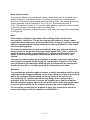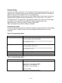
1
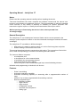
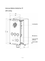
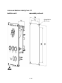
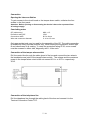
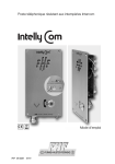
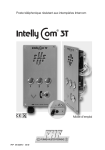
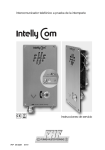
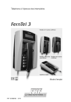
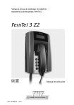
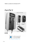
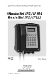
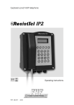
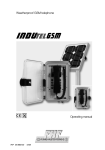
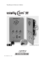
Weatherproof Intercom Station
Operating manual
FHF BA 5228-3
02/12
Operating Manual - IntellyCom 3T
Notes
Please read the operating manual carefully before installing the device.
Texts and illustrations have been compiled and software created with the utmost care,
however errors cannot be completely ruled out. This documentation is therefore supplied
under exclusion of any liability or warranty of suitability for specific purposes. FHF
reserves the right to improve or modify this documentation without prior notice.
Before opening or dismounting the device it has to be separated from
all voltage supply.
General Description
The IntellyCom 3T is a weatherproof Intercom Station which can be operated in the
analogue, public telephone network or can be connected to analogue terminals of branch
exchanges.
The IntellyCom 3T is available in different designs:
• With casing it is made for wall mounting or it can be fixed on pylons and joists.
• Without casing it is meant as built-in unit.
This manual describes below the construction with casing. The connection of the built-in
unit is made correspondingly, but without considering the cable entries.
The Intercom Station comprises
- a loudspeaker and
- a microphone for voice communication
- a hookswitch key as operating element
- three key buttons for direct dialing
- and a LED (part of the hookswitch key)as loop current indicating element.
Utilization and programming is identical in all devices.
Features
-
Pulse / tone dialing
Automativ cleardown capability
Automatic answering capability or answering after a programmable number of
rings
Choice of up to three programmable direct dialing numbers
Remote programming of
•
telephone number
•
ringer volume
•
ringer melody
•
loudspeaker volume
•
automatic call acceptance
•
dialing type
2 / 16
Intercom Station IntellyCom 3T
with casing
Loudspeaker
Microphone
Loop Current
Indicator
Hook switch
key
3 / 16
Intercom Station IntellyCom 3T
built-in unit
assembly cut-out
thread M4 or
Ø 4.3 mm
4 / 16
Connection
Opening the Intercom Station
To gain access to the circuit board or the tamper alarm switch, unfasten the four
screws in the front panel.
Attention: Before opening or dismounting the device it has to be separated from
all voltage supply.
Concluding notes
CE (cable entry)
Protection rating CE
Connection cable
Wire and connector diameter
M20 x 1.5
IP66
Ø 5 to 9 mm
0.14 to 2.5 mm2
Only appropriate tools may be used for the assembly of the CE. The cable connection
is suitable for firmly secured conduits only. When locking the equipment, ensure tight
fit and cleanliness of all sealing. To retain the protection rating IP 66, cover screws
must be screwed in either side, diagonally with 1.4 Nm each.
Connection of the tamper alarm switch
Pull the control line through the cable gland of the box and connect the two wires to
the insulated screw joints of the tamper alarm switch. The voltage and the maximum
power in the tamper alarm circuit shall not exceed 60 VDC or 30 VAC respectively
30 W.
Connection of the telephone line
Pull the telephone line through the cable gland of the box and connect it to the
Terminal Connection Points TCP.
5 / 16
Relay contact output
The Intercom Station board comprises a relay contact which can be activated from a
remote telephone or telephone system. This relay can control for example electric
door entry mechanism, signaling and other electrical devices. The voltage at the relay
contact terminals shall not exceed 60 VDC or 30 VAC. The maximum power is
30 W. The maximum current is 1 A. Another cable gland is needed to connect a cable
to the relay contacts. Exchange it with the sealing plug.
The operating of the relay is described below. In all cases the relay will be deactivated
on hanging up.
Note:
If the switch on button an the chosen direct dialing button will be touch
successively, IntellyCom 3T dials the programmed number or sends a short
signal that the storage space of the touched button is empty. In the last case the
Intercom communication terminal remains occupied and waits for a new touch
of a direct dialing button.
The intercom station disconnects automatically when you and your speaking
partner pause for longer than the programmed pause limit (*13xx*), when your
speaking partner hangs up and IntellyCom 3T detects the telephone’s busy
signal, or when the programmed conversation duration limit (*12xx*) has
expired.
The intercom station mutes the microphone or undoes a previous muting if the
on/off button is pressed briefly during the conversation. IntellyCom 3T’s loop
current indicator light displays a blinking light to indicate that the microphone
is switched to mute, or a continuous light to indicate the active state.
Attention!
To guarantee the protection against contact a voltage equalizing cable has to be
connected to the voltage equalizing screw of the casing or in case of the built-in
unit to the corresponding mounting tab on the inside of the built-in unit.
The IntellyCom 3T complies with the casing design of the casing kind of
protection IP66. For the built-in version the installer has to take care that the
desired protection against water and dust will be achieved by appropriate seals.
In case of deficient built-ins the installer assumes the entire responsibility.
For the casing construction the distance to other live components has to be
constructed safely in built-in condition, see EN 60950-1!
6 / 16
Operation
Making a Call
Touch the switch on button and successively one of the direct dialing buttons to
release a connection to the chosen partner.
The loop current indicator light blinks to indicate that a connection is being made, and
changes to the continuous “on” state, when the receiving party answers the call.
To converse with your respondent, speak in the direction of the Intercom station from
a distance of about 30 cm.
To disconnect, press the on/off button and release when a signal tone announces the
expiration of the programmed minimum press duration (*32xx* (2 s)). The loop current
indicator light will go out and the intercom station will go back to standby.
Receiving a Call
When the intercom station rings, press the on/off button.
The loop current indicator light goes on, glowing continuously.
Conduct your conversation.
To disconnect, press the on/off button as above under “Making a Call”. The loop
current indicator light will go out and the intercom station will go back to standby.
7 / 16
Programming
The Intercom Station IntellyCom 3T is designed to be programmed remotely over the
telephone line. Programming is carried out using sequences keyed from a telephone,
when connected to the IntellyCom 3T to be programmed.
Remote programming codes are split into two classes Class 0 and Class 1 which are
distinguished by different enclosing characters; “#” for Class 0 and “*” for Class 1.
The IntellyCom 3T accepts Class 1 programming codes only if the user has the right
to program. This is achieved by sending the Class 0 programming code
#AccessCode#. The factory setting is AccessCode=1234.
Class 0 programming codes are always accepted.
Programming Codes
For each programming sequence below the telephone responds with an acknowledge
or an error tone. In case of an error tone the programming sequence has to be
repeated.
Class 0 Programming Codes
Code
Function
#accesscode#
Request the programming rights
Factory setting: accesscode=1234
The corresponding programming function refuses the values 0600 and 0990 and
responds with an error tone.
#relaycode#
Activate relay
Factory setting: relaycode=1
The corresponding programming function refuses the values 0600 and 0990 and
responds with an error tone.
#0600#
#0990#
##
Request phone_ID
Cleardown
Deactivate relay
Class 1 Programming Codes
Code
Function
*100dialmode*
Select dial mode
dialmode=1 Tone dialing (DTMF)
dialmode=2 Pulse dialing 1.5:1
dialmode=3 Pulse dialing 2:1
Factory setting:
dialmode=1 Tone dialing (DTMF)
8 / 16
*101disablebusy*
Set up option "Disable in case of busy tone"
disablebusy=0 Disable in case of busy tone activated
disablebusy=1 Disable in case of busy tone deactivated
*102ringback*
Delivery condition:
disablebusy=0 Disable in case of busy tone activated
Set up option "Ring back schema"
ringback=0 Ring back schema 2
ringback=1 Ring back schema 24
ringback=2 Ring back schema 246
*11number_of_rings*
Delivery condition:
ringback=1 Ring back schema 24
Number of rings before automatic answer
number_of_rings=00
Automatic answer without ringing
Microphone and Speaker muted
number_of_rings=01-98 Automatic answer with ringing
number_of_rings=99
No automatic answer
*12t_max_call_duration*
Factory setting:
number_of_rings=03
Maximum call duration
Length of conversation before automatic clear down
t_max_call_duration=00 No limit
t_max_call_duration=01-99 minutes
*13t_duration_of_silence_
before_cleardown*
Factory setting:
t_max_call_duration=00
Duration of silence before automatic cleardown
t_duration_of_silence_before_cleardown=00
Does not clear down on duration of silence
t_duration_of_silence_before_cleardown=01-99 seconds
*140speaker_volume*
Factory setting:
t_duration_of_silence_before_cleardown=28 seconds
Loudspeaker volume
speaker_volume=0-7 0 = mute
Factory setting:
speaker_volume=7
9 / 16
*142duplex_profile*
Set up duplex profile of voice communication
duplex_profile=0-4 (full duplex -semi-duplex)
Delivery condition:
duplex_profile=0 full - duplex
*150ringer_melody*
Remark: In case of inappropriate electrical and/or acoustic
installation conditions co-coupling effects (whistler) may
occur. In those cases modify the regulation of the profile in
to the higher values (semi-duplex).
Ringer melody
ringer_melody=0-8
*160ringer_volume*
Factory setting:
ringer_melody=7
Ringer volume
ringer_volume=0-7
*17t_button_pressed_
before_offhook*
0 = mute
Factory setting:
ringer_volume=6
Duration for which button must be pressed
continuously before the Intercom Station goes offhook
t_button_pressed_before_offhook=00 Immediate
t_button_pressed_before_offhook=01-99 *0.1 seconds
*20t_wait_user_action*
Factory setting:
t_button_pressed_before_offhook=00
Time limit for the user actions touch of direct dialing
buttons and call answering
t_wait_user_action=00 unlimited
t_wait_user_action =01-99 seconds
*25t_relay_on_duration*
*2600*relaycode*
Factory setting:
t_wait_user_action =15 seconds
Relay activation time
t_relay_on_duration=00 unlimited
t_relay_on_duration=01-99 seconds
Factory setting:
t_relay_on_duration=02 seconds
Relay activation code
relaycode=0-9999
except: 0600, 0990 and actual accesscode
Factory setting:
relaycode=1
10 / 16
3000accesscode
Access Code
accesscode=0000-9999
except: 0600, 0990 and actual relaycode
32t_button_pressed_
before_onhook
Factory setting:
accesscode=1234
Duration for which button must be pressed
continuously for clear down to take place
t_button_pressed_ before_onhook=05-99 *0.1 seconds
5000phone_id
Factory setting:
t_button_pressed_ before_onhook=20
Program Intercom Station ID
= 2 seconds
phone_id=0-9999
5001 telephone number
Factory setting:
empty
Program memory M1 for direct dialing button 1
Factory setting:
empty
5002 telephone number
Note: This memory must be programmed as empty memory
if automatic dialing is not required.
M1 is cleared with 5001*
Program memory M2 for direct dialing button 2
Factory setting:
empty
5003 telephone number
Note: Only M1 is dialled if this memory is empty.
M2 is cleared with 5002*
Program memory M3 for direct dialing button 3
Factory setting:
empty
980factory_settings_
option
Note: Number chaining ends with memory M2 if memory
M3 is empty.
M3 is cleared with 5003*
Return to factory settings / Erase Memories
factory_settings_option=0 Factory Settings
factory_settings_option=1 Factory Settings,accesscode
and relaycode unchanged
factory_settings_option=2 Erase memories M1-M3 & M100
11 / 16
*5100* pstn_prefix*
*9900*
Program memory M100 PSTN_PREFIX
Factory setting:
empty
The deletion of M100 is done by *5100**
Disconnect
*9901*
Reactivate loudspeaker
Defining Call Procedures
Determine the call chosen from the storage places.
Determine the call chosen from the storage places.
You determine this setting by programming at least one of the three direct dialing
storage places M1-M3.
After touching the switch on button and the direct dialing button the communication
terminal immediately tries to build-up a connection to the partner. The action is
terminated by the successful realization of the connection or the deactivation of the
communication terminal, if the programmed time limit *20xx* (15 s) runs out.
Example:
#1234#
Getting the permission to program
*5001*101*
Direct dialing button 1 programm the linked storage button and
determine the partner number e.g. 101.
*5002*102*
Direct dialing button 2 programm the linked storage button and
determine the partner number e.g. 102.
*5003*103*
Direct dialing button 3 programm the linked storage button and
determine the partner number e.g. 103.
*2015*
set time limit e.g. 15 s, to determine, how long IntellyCom 3T shall
wait, if the user touches a direct dialing button and that the called
partner accepts the call.
If the no direct dialing or call acceptance is realised, the IntellyCom 3T
deactivates itself after the expiry of the chosen time limit.
Defining Call Acceptance Procedures
To Define Automatic, Mute Call Acceptance with the First Ring/Signal
You can define this call acceptance scenario by setting the programmed ring/signal
counter *11xx* (3) at the value “00”. Incoming calls to the station will then be signaled
optically and accepted automatically with the first signal. In contrast to the other call
acceptance scenarios, the speaker and the microphone are muted.
12 / 16
Example:
#1234#
Receive programming authorization.
*1100*
Set ring/signal counter to the value “00”, to define automatic call
acceptance after the first signal.
To Define Automatic Call Acceptance after “n” Rings
You can define this call acceptance scenario by setting the programmed ring/signal
counter *11xx* (3) to the desired value within a range of 1 - 98. Incoming calls will
then be acoustically1) and optically signaled by the station and automatically accepted,
when the set number of rings/signals has been reached.
Example:
#1234#
Receive programming authorization.
*1103*
Set ring/signal counter to the value “3”, to set the automatic call
acceptance at 3 rings.
1)
With a programmed ring volume of *1600*, the speaker is muted when the call is
being signaled.
To Define Manual Call Acceptance
You can define this call acceptance scenario by setting the programmed ring/signal
counter *11xx* (3) to the value “99”. Incoming calls will then be acoustically1) and
optically signaled, and only accepted when the on/off button is pressed.
Example:
#1234#
Receive programming authorization.
*1199*
Set call counter to the value “99”, to shut off automatic call
acceptance.
1)
With a programmed ring volume of *1600*, the speaker is muted when the call is
being signaled.
13 / 16
Problem handling:
Unexpected disabling of any communications (call/call reception)
You start a call or receive a call and the communication is more or less immediately
disabled.
This problem may occur, if the IntellyCom or set of your interlocutor is installed in a
noisy environment. If those ambient noises hit the busy tone schema of the
IntellyCom, it considers the connection as disabled by the interlocutor and switches
off.
You can switch off the operation mode „disable in case of busy tone“ by setting the
option *101x* (0) to the value 1. Please note, that in a noisy environment the
operation mode "Disable in case of continuous silence *13xx* (28 s)" will also be
affected. To guarantee an automatic disabling of the IntellyCom, the maximum call
duration, which in the delivery condition is adjusted to infinite *12xx* (0 infinite), should
be limited to a convenient value.
Example:
#1234#
*1011*
*1205*
Obtain the programming authorization.
Set option "disable in case of busy tone" to the value 1, to deactivate
the disabling in case of identified busy tone.
Determine the maximum call duration to e.g. 5 min., to guarantee that
the IntellyCom switches off automatically.
Unexpected muting at the beginning of outgoing communications (call)
You start a call; your interlocutor answers the call and does not hear you at the
beginning.
This problem may occur, of the IntellyCom does not understand the message of your
interlocutor and continues the supervision of the calling phase with muted microphone
and flashing loop current display.
You can manually stop the muting function by a short activation of the activation
button and/or by selecting that IntellyCom ring back schema, which is able to
distinguish earliest language and ring back tones. A reliable identification of the call
begin cannot be guaranteed with none of the ring back schemas, schema 2 offers the
lowest error rate.
Example:
#1234#
*1020*
Obtain the programming authorization.
Set option "Ring back schema" to the value 0, to select schema 2.
14 / 16
Connection information
Input terminal voltage
Power supply current
Call signal voltage
Call signal impedance
Dialling method
Connecting terminals
Relay contact points
Tamper contact
24 VDC to 66 VDC from the telephone connection
28 mADC to 100 mADC
35 VAC to 90 VAC (23…54 Hz)
Larger 5.5 kW at 25 Hz and 30…90 VAC
Larger 4.0 kW at 50 Hz and 30…90 VAC
Dual-tone multi-frequency signalling (DTMF)
Pip-tone dialling; pip-tone interval ratio 1.5:1 or 2:1.
Max. 2.5 mm2
Max. 30VAC
Max. 60VDC
Max. 1 Aeff
Max. 30 W
Max. 30VAC
Max. 60VDC
Max. 30 W
Built-in unit
Dimensions
With casing
Material
Height x Breadth x Depth
Weight
Scanner
VA
Front Panel VA
Approx. 205 x 110 x 60 mm Approx. 205 x 110 x 55 mm
Approx. 1.2 kg
Approx. 0,65 kg
Metal scanner made of VA with integrated red LED
Environmental conditions With casing
Built-in unit
Protection type:
Operating temperature:
Storage temperature:
IP 66 (frontal)
IP 66 as per EN60529
-40°C to +60°C
-40°C to +70°C
Other features
Call volume
Call melodies
Minimum call duration
until automatically
engaged
Call pause duration for
call pause bypass
Speaker
- 7 levels and silent
- Maximum approx. 80 dB(A) at a distance of 1 m at 50 VAC / 50Hz
9 melodies
≥ 800 ms without interruption (call diversion not permitted)
2…6s
- Maximum volume approx. 68 dB(A) at a distance of 1 m
- Volume 7 levels
Directives and regulations
- R&TTE directive 1999/5 EC
Conformity with the
following directives and
- Low voltage directive 73/23/EEC
regulations:
- EMC directive 89/336/EEC for residential and industrial zones
15 / 16
Subject to alterations
or errors
FHF Funke + Huster Fernsig GmbH
Gewerbeallee 15-19 · D-45478 Mülheim an der Ruhr
Phone +49 / 208 / 82 68-0 · Fax +49 / 208 / 82 68-286
http://www.fhf.de · e-mail: [email protected]