1
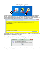
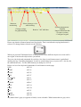
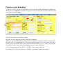
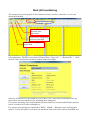
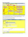
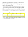
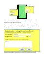
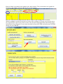
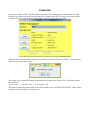
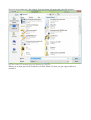
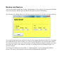
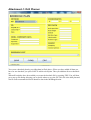
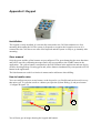
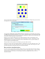
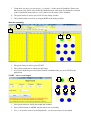
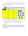
User manual
Envi logger G1
Version: R1C
Date: 2012-03-19
Contents
Innehållsförteckning
General.................................................................................................................................................3
Starting the system...............................................................................................................................4
Prepare a new Sounding.......................................................................................................................7
Create a drilling plan........................................................................................................................8
Start drill monitoring............................................................................................................................9
Execute the sounding.....................................................................................................................11
Add notes/Comments during sounding..........................................................................................11
Open window with large text for parameter values.......................................................................12
View data for stored boreholes...........................................................................................................16
Create file...........................................................................................................................................19
Resuming borehole data registration..................................................................................................21
System Management..........................................................................................................................22
Backup and Restore............................................................................................................................23
Attachment-1: Drill Planner...............................................................................................................24
Appendix-2: Keypad..........................................................................................................................25
Installation.....................................................................................................................................25
User manual...................................................................................................................................25
How to handle notes..................................................................................................................25
Menu selection using blue buttons............................................................................................26
Main window........................................................................................................................27
NEW dialog..........................................................................................................................27
Start the sounding.................................................................................................................28
During drilling......................................................................................................................29
STOP sounding.....................................................................................................................29
General
Envi logger G1 is a PC based data logger where all sensor data is stored in a database on the PC.
Sensor data is stored in a raw format as measured by, or as sampled immediately after, the sensor.
Data for all sensors present at the rig is stored continuously. Thus enabling access to all measure
data at any time after drilling is finished.
Data is transferred from sensors to data logger over a CAN bus (CANopen). As a result the system
is not sensitive to noise from external or internal sources. In an analogue system all received noise
is added to the data as opposed to a digital system.
The user can determine what parameters to look at while drilling and what parameters to include
when creating a file.
Currently available file formats are SGF/STD format or a tab separated format that is easily
imported into Excel or equivalent software. More formats will be added based on customer
requests.
All personal settings done by the user are remembered by the system and will be used for future
usage until they are changed.
The software is divided into three applications:
EnviPackage
The platform/driver handling sensor readings and database communication
CptApplication
Application started if you want to work with CPT
MWDapplication
Application started if you want to work with MWD
Starting the system
1
2
Programs (2) are started by double clicking the icons. Only one application may be started at any
one time. The enviPackage icon is there for historical and diagnostic reasons. When you have
started the application by double clicking the icon for it all processes for database handling etc are
initiated. This takes some time and you will receive a wait dialogue like below:
As soon as the application is started and ready to use this pop up window is closed and you see the
main window for the application (see next page).
If something goes wrong you will be notofied by a pop up window with error information.
If you start the application without being connected to the gateway box or if there is something
wrong with the connection you will have a pop up telling this (see below).
When you confirm this pop up the system will be started in off line mode, where you can view old
soundings, create files etc.
Start new
monitoring
Select sensors to view
while drilling
Change settings
for graph drawing
Retrieve ”old” drill data
System management:
- Backup
- Import calibration data
- Get new versions
- Configure keypad
Please note that the leftmost button has a blue border. That is an indication saying that button is
selected. To change button selected use the TAB-key.
When you press the TAB button focus is changed between the different objects on screen until it
once again is back on the object where you started.
There are also keyboard commands for each key. One letter in each button name is underlined
marking the key controlling that button. In order to control those keys you press ALT+<the key for
the underlined letter>. For the NEW button you shall press ALT+N.
Below is a list of the keyboard commands for each button on main page:
NEW
ALT+N
START
ALT+S
PAUSE
ALT+P
STOP
ALT+T
SETTINGS
ALT+I
VIEW
ALT+V
SCROLL
ALR+C
NOTE
ALT+O
DATA
ALT+D
FILE
ALT+F
ERASE
ALT+R
BACKUP
ALT+B
Any button that is gray (as opposed to black) is non selectable. What buttons that are gray varies
during operation depending on what you are currently doing. Initially buttons for START, STOP,
PAUSE and FILE are gray since there there is not yet any drilling in progress nor drill data retrieved
from database.
There are two basic options for how to proceed:
1. Start new borehole monitoring
2. Retrieve data for earlier boreholes from database
In addition to the above mentioned selections you may also select SETTINGS giving you the option
to change different parameters. More about this later in this document.
The NOTE button is not gray but has no function at this time. This is true also for SCROLL button
since no graph is presented on screen.
Prepare a new Sounding
If you select “NEW” you get a pop-up where you are expected to define administrative data for the
drilling. You are required to to define at least project name, borehole ID and drill method to be able
to save and close this dialogue.
List of available
drill methods
List of your most used
drill methods
The other text fields are optional to register.
Presently you are required to manually enter GPS coordinates.
When you open the NEW dialogue fields will be automatically populated with data from previous
borehole since it is assumed that data will be pretty much the same from one borehole to the other.
When you have entered the data required plus any additional data you press ”SAVE” and you will
be transferred to the main window again and the system is ready for drilling.
To erase all data from the form choose “CLEAR”. If you change your mind.
If you change your mind you can select “ABORT” to go back to main frame/window.
Create a drilling plan
In upper right corner of NEW dialog there is a button called IMPORT. If you want to import a drill
plan you press this button. You will then get a file dialog where you can select the file you want to
use.
The planned drill holes imported in the drill plan will then appear in the drop down menu under the
import button. If you mark the “USE” check box, the system will automatically select drill holes in
the order they were added to the plan but you can also select yourself.
To create the drill plan you use a tool that you can order from Envi. Please refer to Attachment-1:
Drill Planner for more information about this tool.
Start drill monitoring
The system now presents graphs for the parameters/sensors you have selected to view for the
chosen drill method.
Press START to start
borehole data
registration
Press PAUS to temporarily
halt data registration
Press STOP to end data
registration
If you want to change graphs to view during drilling press ”VIEW” (see red marking above) and
select parameters. The ID for a borehole is built up from “Project ID” + “Borehole ID” + “Drill
method” and is written into text boxes marked with a blue ellipse.
Select the check boxes for the parameters you want to view. Some boxes are disabled since the
system does not have transducers for measuring those parameters.
For systems measuring force from hydraulic pressure both Force pressure and hold back pressure
can be viewed as well as the resulting force.
For systems using having two chucks all of “RPM”, “RPM2”, “Rotation count” and “Rotation
count 2” will be selectable. If you chose one parameter from each chuck (such as both RPM and
RPM2) the system will combine data from the two into one graph and one parameter when file is
created. Data is gathered from chuck-1 (RPM + Rotation count) when hammer is off and from
chuck-2 (RPM2 + Rotation count 2) when hammer in on. So data is only gathered from one chuck
at a time and which one is controlled by hammering being on or off.
To start the drill monitoring press “START”. A dialogue for defining start depth appears.
You can define start depth
by either entering it using arrows
for meter, decimeter and centimeter
or you can enter depth directly into
the Depth text field.
You change meters, decimeters and centimeters by pressing up/down arrows. When you change
these the system, calculates the total start level in centimeters and presents it in the text field.
To save the start depth defined and start the drill monitoring press “SAVE” button (ALT+S). If
“ABORT” is selected no monitoring is started and you are back to main window.
When you have pressed the “SAVE” button in the start depth dialogue the monitoring is started. As
soon as the depth increases graphs are now plotted for the parameters you have selected. Parameter
values can also be seen in the upper part of each frame and in text fields between buttons and
graphs.
Execute the sounding
If you want to change
settings, press SETTINGS
Hammer
on/off mark
To resume a sounding that
has been interrupted
Red squares
are notes
Press NOTE to open dialog for
adding note
For manual registration of “Hammer on/off” and “Flush on/off” you press radio buttons in the main
window (see red oval in picture above). The radio button shall be marked/filled when hammer/flush
in on and not marked when hammer/flush is off. The note ”20: Hammer Start” and ”21: Hammer
Stop” are automatically added when “Hammer on/off” button is marked or unmarked.
Add notes/Comments during sounding
During borehole data registration you can add notes.
rea
A
t
Tex
NB: The note will not become visible in graph window until new depth is registered or the data registration is
terminated
In the drop down menu ”CODE” there are some predefined codes. The depth text field will be
populated with the depth that was when the NOTE button was pressed.
You can create your own codes by using code numbers not already used and create your own
standard notes with the code number selected and any text of your choice. The available codes are
found in the “Custom Code” drop-down menu.
You can also use free text notes written in the text area. Such notes will be stored as regular notes
with the text you have entered in the Text Area above and they will all be given code “0”.
To save the comment with the drill data press “SAVE” (ALT+S). If you change your mind and no
longer want to add a note press ABORT. Note dialogue is closed when you press any of the two
buttons.
In the graphs in the main window you can update the notes by clicking on them and change data in
the dialog that pops up. If you only want to change depth for a note you can simply drag and drop it
to the depth where you want it positioned.
Open window with large text for parameter values
You can see 5 parameters as large text. Depth is mandatory but the other four can be selected from
the available sensors. You can have different parameters as large text for different drill methods.
The system remembers your choice for each method.
To change graph settings you press the “SETTINGS” button under GRAPHS. You then get the
dialogue below with several options available:
Define if rod weight
shall be added to force
You can define boldness
of lines and size of note
rectangle
You can chose unit of measure
for ROP to mm/sek or cm/min
and also if force shall be in
metric tons or kN
You can chose automativ or manual
detection of hammer and fluch on/off.
NB. To have automatic detection sensors
must be mounted
Specify if you want bars or floating
average for counters (number of
rotations and number of blows).
You can also specify width of bars
to 10, 15 or 20 cm.
Define how you want notes to
be presented in the graphs Notes
will be printed in file in the
same format as presented in
graphs. If you show code and
text both will come out in file
Define if deepest depth or
actual/current depth shall
be given
You can define whether notes
for hammer- and flush on/off
shall be generated or not
Off = Not checked
On = Checked
To save settings press “SAVE” (ALT+S), or press “ABORT” (ALT+A) to exit without saving
anything and go back to main window. Settings are saved by the system and used until changed.
Some values will change immediately when you change values in the above dialog, but the system
will only use them temporarily and will not remember the setting until SAVE has been pressed.
To change scale settings for a parameter you press with right mouse button somewhere to the right
of the vertical coordinate axis (The depth coordinate axis) in the graph for that parameter.
This area is marked with greenish color below.
If you want to change the scale for depth you must click with the right mouse button to the left of
the vertical coordinate axis. This area is marked with greyish color above.
Select the scale of your choice and press SAVE.
If you want the system to save a file automatically after each borehole and if you want the file also
to be sent by email directly after completion of probing you can define the settings for it in the
dialog you get up if you press the button "File & E-mail ". This dialog is depicted below.
If you tick the "Create files automatically after each drill hole" a file is created directly after
completion of the borehole (completed when STOP in the main window has been pressed).
To be able to tick the "Send files automatically" one must first have selected the "Create files
automatically after each drill hole" so that a file is created. You must also set your preferences to
send Email. You enter the same settings as for your regular email account. You can find information
in the account settings in your email client. Ask your PC technician for help if you do not know
how to obtain such information. If you choose to send Email automatically after completion of the
wells, you will be prompted for your password the first time that the system sends E-mail after
having started. The system will then remember the password until it shuts down. For security
reasons the password is deleted from the system when it shuts down.
View data for stored boreholes
In order to view recorded borehole data press “DATA” button. You then get a dialogue where you
can filter boreholes to find the one you are looking for. You can use the Latest 20 drop down menu
if you want to select between latest recorded boreholes. Alternatively you select borehole by
filtering using a span of dates and then if desired pick one project and then you get all boreholes for
that project in the “RETREIVED SOUNDINGS” menu. Then you can select any borehole from the
list and press “OPEN” to get data for the borehole presented.
Select to retrieve recorded
soundings between start
date
and end date
Here all projects with boreholes between dates as
per
above are presented. It is enough that there is one
borehole for a project between the dates above to
cause the project id to appear here
Here all borehole data logs
matching the given search
criteria will be available
Here 20 latest borehole
data logs are available
When a borehole has been selected and the date text field is populated with the date for drilling the
hole selected.
The maximum depth of the borehole is printed in the Depth text field (with a blue ellipse around
below).
Retrieved data is presented in the graphs in the main window. The system shows only graphs for
parameters that will be printed to file for the specific method
Now you can look at the graphs and also add new notes or edit existing notes if desired.
When a sounding is open you can chose to create a file or delete it. Of course you can also start a
new registration or quit. If you want to create a file just press FILE and follow instructions (more
information in later chapters). If you want to do that you press SYSTEM and in the pop SYSTEM
dialog you press ERASE.
You can now chose what to erase:
1. A complete project. Select the project you want to erase and then press button ERASE
2. One specific sounding. First select a project from project menu and then select a sounding
from the sounding menu. Press ERASE and the selected sounding will be erased.
3. All soundings from oldest and up to a certain date. You specify the date up to which all
soundings will be erased. Mark the check box and press ERASE. Now all soundings created
before or on the specified date will be erased.
If you chose to erase the data you will be requested to confirm that before the data is erased.
NB: IT IS NOT POSSIBLE TO UNDO ERASING DATA ONCE IT HAS BEEN DONE!
Create file
If you press button “FILE” after finishing a borehole or after having retrieved data from recorded
boreholes you must first select what parameters to include in the file. The choice you make will be
remembered by the system and used as default parameters for next file creation.
When you have selected what parameters to include in the file and pressed “SAVE” you must chose
what file type you want to create:
The system sets a default file name for the borehole for which you create a file. That name is built
up as follows:
”project name”_”borehole name”_”drill method”.std.
The name is hence the same as data in the ID text fields in the “SAVED SOUNDINGS” panel. These
fields are in the red ellipse two pictures up.
You now get a regular save file window. You can change file name and select file location:
Sorry this window is in Swedish since I have that language on my PC
When you are done press SAVE and file is created. When it is done you get a pop window to
confirm it.
Resuming borehole data registration
If you have stopped a borehole data registration and want to resume that registration you press the
RESUME button. This works also if you load data from database. When you press RESUME new
data registration will be added to the currently loaded/visible data.
So you can resume registration for the borehole currently on screen
When you have pressed RESUME the registration for the selected borehole is reopened. To start the
registration again you now press START which will open the start depth dialog. Press SAVE to
resume the sounding.
Please note that the START button is now disabled showing that registration for the borehole has
been resumed.
System Management
To send log files to Envi press SYSTEM. You will then get the SYSTEM dialog where several tasks
can be done.
You can request the system to create log files. If your PC is not connected to the logger system only
log files from applications will be compiled. If your PC is connected to the logger system and the
system is running, parameters such as calibration etc will also be gathered and included in the zip
folder. If you want to send log files by pressing button Send log file with @, you must have entered
the correct data for your Email Account in the dialogue for sending borehole data (see chapter User
Settings above).
In this dialog there are also functions for updating both the application software and the system
calibration. If you press DOWNLOAD LATEST VERSION when your PC is connected to the
Internet the application will look for newer versions and if found request to download it. You then
install the new version by double clicking the downloaded msi file.
If you have received a new calibration file from Envi you imprt it to the system by pressing
UPDATE CALIBRATION and then you chose the calibration file in the file selection dialog.
ERASE has been covered in earlier chapters.
CONFIGURE KEYPAD is described in chapter about the keypad.
Backup and Restore
You can always back up the data you have in the database. This is done by pressing first SYSTEM
in the main window and then press the BACKUP button in the SYSTEM dialog.
You will then get a dialog where you enter the start and end dates for the data you want to backup.
You specify the dates between which you want to store backup data and press RUN. If you change
your mind and do not want to backup, you cancel by pressing on the cross and close the window.
To restore the database from a previous backup or load the backup on another computer, you must
first enable the restore of the database, open the user settings and set the Backup possible (see
previous chapter).
The backup file shall be placed in folder “C: / EnviLoggerG1 /” prior to starting the database
restore. The name of the backup file shall be ENVILOGGERG1BACKUP.ZIP
Attachment-1: Drill Planner
You create a borehole plan by providing data in fileds above. When you have added all data you
have for one borehole you press SAVE to add it to drill plan. Then you add data for next borehole
etc.
When all boreholes have been added you create the borehole file by pressing FILE. You will then
get a pop up file dialog allowing you to decide where to save the file. This file is the drill plan and
can be used to automate drill hole identifier data in the MWDapplication.
Appendix-2: Keypad
Installation
The keypad is easily installed. It is electrically connected to the CAN bus and there are four
mounting holes under the lid. The system is prepared to recognize the keypad as soon as it is
connected to the CAN bus so no extra effort required and the system is ready to go instantly after
mounting.
User manual
Only the green and the yellow buttons are preconfigured. The green button has the most functions
and will be used for confirming messages and it also corresponds to the START button in the
application. The yellow button corresponds to the PAUS button in the application and can also be
used for aborting dialogs. Pressing green and yellow buttons simultaneously corresponds to STOP
button in the application.
The blue buttons are used for selection in menus and to add notes when drilling.
How to handle notes
You can configure any note to any button, so the keypad is very flexible and can be used in a way
that suites you. To correlate a note to a button you open the System Dialog (1) and press button
“Configure Keypad” (2).
1
2
You will now get an image showing the keypad and buttons:
You press the button in that image that you want to. You will then get a dialog where you can select
the appropriate note for the button.
You can chose standard notes (SGF standard) from the Code menu or you can make your own note
by adding any text (Allowed characters: a-ö, 0-9, space) in the Free text area. You can not have both
an SGF note and a free text note associated, only one is applicable. When you have chosen the code
to associate with the button/key you press SAVE.
Buttons can correspond to different notes for different methods. If the note shall apply for all
methods that does not have a method specific note for the button you select “Not Selected” in the
METHOD menu. If you want to correlate the note for that button for only a specific method you
select a method in the METHOD menu.
This procedure is then repeated for each button you want to add a code for.
When you are done remove the keypad window by clicking the cross in the right upper corner. The
keypad is now ready to be used. Keys that have not been associated with a note will give no result
but other buttons/keys will generate the note associated with them.
Menu selection using blue buttons
In some cases the system will open dialog windows where you can make manu selections. In those
cases you can use blue buttons to select items in these menus. This applies only to “regular” dialogs
and menus that you will always use when doing an ordinary sounding. Below these cases are
described in detail.
Main window
The only useful button at this stage is the green button for pressing NEW and initiating a new
sounding.
NEW dialog
2
4
5
3
1
3
2
1
+
+
+
-
-
1. The trailing number in the borehole ID is increased by one every time you press this button.
NB. Borehole ID must end with a number if this function shall work, e.g. sounding-1 or
”TheHill345” or similar. Please also note that the number can not be decreased using the
keypad only increased
2. Using these two keys you can go up (+) or down (-) in the menu All methods. Please note
that you can only chose items in the All methods menu when item Not Selected is selected
in the My Methods menu and vice versa. Otherwise the menu will be disabled
- - - - - The list continues on the next page - - - - -
3. Using these two keys you can go up (+) or down (-) in the menu All methods. Please note
that you can only chose items in the My Methods menu when item Not Selected is selected
in the All methods menu and vice versa. Otherwise the menu will be disabled
4. The green button is used to press SAVE in the dialog window
5. The yellow button is used for pressing ABORT in the dialog window
Start the sounding
1
1+2
2
1
1. The green button is used to press START
2. The yellow button has no function at this stage
3. If you press both the green and yellow buttons simultaneously you press STOP in the
application
START – select a start depth
1
+
3
-
2
+
+
4
5
-
-
1. Press green button to SAVE start depth and continue
2. Press yellow button to ABORT and not start a new soounding
3. Use (+) to increase meters in start depth and (-) to decrease meters in start depth
4. Use (+) to increase decimeters in start depth and (-) to decrease decimeters in start depth
5. Use (+) to increase centimeters in start depth and (-) to decrease centimeters in start depth
You can not select start depth with millimeter resolution with the keypad but this is probably very
uncommon and should not be a problem.
During drilling
1
1+2
2
1
2
1. Use green button to press START when adding a new rod or for exiting a paused state
2. Use yellow button to PAUSE the sounding and stop data regsitration temporarily
3. Blue buttons will generate notes according to what you have programmed
4. Press both green and yellow buttons simultaneously to STOP the sounding and discontinue
data registration.
STOP sounding
The sounding is stopped by pressing STOP. This is done by simultaneously pressing green and
yellow buttons on the keypad. You will then get a popup dialog requesting a stop code. The first
stop code is 90 and will be selected by default. You can select other codes by stepping up and down
in the menu using buttons (3) on the keypad. When the appropriate stop code is selected you press
the green button to SAVE it.
- - - - - See image below - - - - -
1
2
3
+
1. Press green button on keypad to SAVE the stop code
2. Press yellow button to ABORT and return to the sounding
3. Press blue button (3) marked with + to step to the next code or – to step to the previous code