1
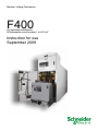
Medium Voltage Distribution
F400
Air insulated switchboard
Withdrawable circuit breaker 1 to 40.5 kV
Instruction for use
September 2009
Content
Note: the subject of this new version of this user
guide is about the annexe “Adaptation/instructions
- Replacement of the voltage presence type VPIS 1
by type VPIS 2 and VPIS 2 by VPIS 2”,
updated on july 2009.
General description Glossary
Cable incoming or outgoing cubicles
Bus coupler cubicles
Bus riser cubicles
Draw-out SF circuit-breakers
Draw-out bar bridge
Identification
How to read the information on the front side
Symbols
List of optional accessories available with the switchboard
Operating Instructions
How to extract the removable part
How to insert the removable part
How to plug in the removable part (bottom front plate)
How to draw-out the removable part (bottom front plate)
How to close the MV cable earthing isolator (top front plate)
How to open the MV cable earthing isolator (top front plate)
How to operate the adjustable voltage transformers
Padlocking
Key-locking
Testing
“Power on” on the MV cables
Checking phase coincidence between two cubicles
Testing MV cables
Switchboard dielectric test
Testing the current transformers
Busbar earthing truck
Maintenance Instructions
version G0
8
8
9
11
12
13
14
16
18
20
21
21
21
21
22
22
23
24
Ordering parts
Preventive maintenance
Maintenance points
Access to top and bottom plug-in blocks
Access to the voltage transformers
Replacing the fuses of the adjustable voltage transformers
Replacing the VT position auxiliary contacts
Replacing the “power on” Led block
Replacing the earthing isolator position auxiliary contacts
Replacing the removable part position auxiliary contacts
Trouble-shooting
24
24
24
25
27
28
29
29
30
31
32
Annexe
33
Adaptation/instructions - Replacement of the voltage
presence type VPIS 1 by type VPIS 2 and VPIS 2 by VPIS 2
07897171EN.indd
2
2
2
3
4
5
5
6
6
7
7
33
General description
Glossary
Abbreviations
Warning: all dimensions are in cm.
LV: low Voltage
MV:36 kV voltage class
EI: earthing isolator
SF: range of SF6 circuit-breakers
used in the F400
VT: Voltage Transformer
NVC: no-voltage check
CT: Current Transformer or current sensor
CT Add: second row of current
transformer.
Cable incoming
or outgoing cubicles
Front side
A: LV compartment access door
B: removable part compartment access
door
C: removable part position check view ports
D: removable part interlocking and operating
plate
E: voltage indicators
F: earthing isolator interlocking and operating plate
G: removable part blocking.
Left-hand view
1: LV cable routing and connection
compartment
2: low voltage compartment
3: busbar compartment
4: MT and VT cable compartment
5: removable part compartment
H: removable part
J: earthing isolator
K: earthing isolator operating mechanism
L: voltage transformer.
version G0
07897171EN.indd
General description
Bus coupler cubicles
Front side
A: LV compartment access door
B: removable part compartment access
door
C: view ports
D: removable part interlocking and operating
plate
E: removable part interlocking plate.
Left-hand view
1: LV cable routing compartment
2: low voltage compartment
3: bottom busbar compartment
4: top busbar compartment
5: removable part compartment
F: removable part interlocking mechanism
G: removable part
H: voltage transformer.
07897171EN.indd
version G0
General description
Bus riser cubicles
Front side
A: LV compartment access door
B: fixed bar bridge compartment
access door
C: view ports.
Left-hand view
1: LV cable routing compartment
2: low voltage compartment
3: bottom busbar compartment
4: top busbar compartment
D: voltage transformer.
version G0
07897171EN.indd
General description
Draw-out SF circuit-breakers
SF1
CEI 1250 A standard
SF2
CEI 1250 A standard
SF2
CEI 2500 A standard
Draw-out bar bridge
1250 A and 2500 A
07897171EN.indd
version G0
General description
Identification
Functional unit
A: cubicle name
B: firm plate
C: features, descriptions and serial
number.
SF draw-out removable part
C: features, descriptions and serial
number.
1: mechanical opening push-button
2: removable part position selector
3: removable part operating crank
insertion aperture.
A: removable part mechanical position
indicator
B: slot for the disconnecting truck
lock (optional).
How to read the information
on the front side
Removable part
Earthing isolator, power on
and plug-in disabling
L1
L2
A: power-on indicator block
B: earthing isolator position selector
C: slot for the earthing isolator lock
D: earthing isolator operating crank
insertion opening
E: locking pull for plug-in disabling
(plug-in disabling selector)
F: slot for the plug-in disabling lock.
L3
5
4
O
version G0
07897171EN.indd
General description
Symbols
“Plug-in disabling” position
Cubicle
“Operating” position
Earthing isolator open position
Earthing isolator open mechanical indicator
Earthing isolator closed position
Earthing isolator closed mechanical indicator
Padlockable position.
Removable part
“Operating” position
“Plugged-in” position
“Drawn-out” position
“Insertion / extraction” position
List of optional accessories
available with the switchboard
07897171EN.indd
version G0
b 1 busbar earthing truck (optional),
see ”Busbar earthing truck”.
b 1 phase coincidence checking device
(optional), see ”Checking phase
coincidence between two cubicles”.
Operating Instructions
How to extract
the removable part
and
Earthing isolator
b Selector 4 to
(earthing isolator
open).
Initial status:
Removable part
The removable part is drawn out.
b The cubicle is in disconnected
position.
Open the access door to the removable
part by pulling and then rotating the
handle rightwards.
Unplug the LV auxiliary connection
cord.
Clip the cable on the circuit-breaker.
Operation
Warning: for cubicles with internal arc withstand
option, loosen the 6 screws A before operating
the handle.
Press push-button 1.
Hold it down to move selector 2 to
Warning: the threshold bar must be removed before
extracting the removable part.
1
position
.
Then extract the removable part by
pulling the handles
Pull out the removable part.
Threshold bar
version G0
07897171EN.indd
Operating Instructions
Closing the door after extracting
the removable part
Warning: the following steps MUST be
followed to allow the door to be closed.
Warning: put back the threshold bar.
Before closing the access door to the
removable part, bottom the panel A.
Inside the door, pull locking part 1.
Rod 2 goes down.
The door closes but does not lock.
Close the door.
How to insert the removable part
Open the access door to the
removable part by pulling and then
rotating the handle rightwards.
Warning: put back the threshold bar.
Insert the removable part in the cubicle.
07897171EN.indd
version G0
Operating Instructions
1
V
To move selector 2 to position
,
press push-button 1.
Hold it down to move selector 2
to position
Warning: lift protection flap V of pushbutton 1.
Connect the LV auxiliary connection
cord.
.
Push the removable part into the
cubicle until its is in abutment.
Then press push-button 1.
Hold it down to move selector 2 back to
position
.
Putting back the threshold bar
Insert the threshold bar A tilting it
slightly, align slots B with threaded
rods C, then fit the threshold bar.
Loosen nuts D.
Closing the door with the removable
part in place
Warning: if closing is impossible, check the following
points given in E and F.
10
E: before closing the access door to the
removable part, lift the panel and check
that it is properly latched at the top.
F: Lift rod 2, topple locking part 1 over
and release rod 2.
The door closes but does not lock.
Close the door.
version G0
07897171EN.indd
Operating Instructions
How to plug in the removable
part (bottom front plate)
Initial status
Removable part
b The removable part is drawn
out. Operation should be allowed
by means of the locks, if fitted.
The circuit-breaker LV auxiliaries
are connected and the circuitbreaker compartment door is
closed.
and
L1
L2
Sectionneur de terre
b Selector 4 to
(earthing
isolator open)
b Locking pull to disable plug-in
in unlocked position.
L3
5
O
Operation
4
If it is key-locked: insert the key
in H.
Bottom the protection flap of
push-button 1.
Press push-button 1. Hold it down
to move selector 2
to position
.
Lift the protection flap of pushbutton 1.
Insert the crank in aperture 3.
Plug in the removable part by
rotating the crank clockwise until
status change of position indicator
A and locking of crank in rotation.
Move selector 2 to position
.
The removable part is plugged-in.
If a circuit-breaker is used, the
electrical operation for switching
on the downstream part of the
equipment is now possible.
07897171EN.indd
version G0
11
Operating Instructions
How to draw-out the removable
part (bottom front plate)
Removable part
b Removable part in plugged-in
position.
Initial status
Operation
If it is key-locked (optional):
insert the key in H.
Bottom the protection flap V of
push-button 1.
Press push-button 1 (which
triggers a circuitbreaker
mechanical opening order).
Hold it down to move selector 2
to position
.
Lift protection flap V of pushbutton 1.
Insert the crank in aperture 3.
Draw out the removable part
by rotating the crank counterclockwise until status change
of position indicator A.
Move selector 2 to position
.
The removable part is drawn out.
The cubicle is in disconnected
position.
Final status
12
version G0
07897171EN.indd
Operating Instructions
How to close the MV cable
earthing isolator (top front plate)
Its function:
b In closed position, it short-circuits
and earths MV cables, making it
possible to work on cables in safe
conditions..
b it can be closed only if the circuitbreaker is in drawn-out position or
extracted from the cubicle.
Initial status:
b The removable part has been
drawn out or extracted from the
cubicle.
or
and
L1
L2
L3
5
A
O
Earthing isolator.
Check that the Leds (L1, L2, L3)
are off (no voltage).
The earthing isolator is open(4).
The locks is fitted (A and B) should
allow operation.
4
B
Operation
L1
L2
Move selector 4 to
L3
, pulling
then rotating it clockwise.
5
O
07897171EN.indd
version G0
4
13
Operating Instructions
L1
L2
Insert the crank in the operating shaft 5,
rotate it clockwise until status change of
position indicator E.
L3
5
L1
L2
4
O
Move selector 4 to , to do so, pull then
rotate it clockwise.
L3
5
L1
L2
4
O
The earthing isolator is in closed
position.
MV cables are short-circuited and
earthed.
L3
5
4
O
How to open the MV cable
earthing isolator (top front plate)
L1
L2
Initial status:
b Earthing isolator closed.
If fitted, lock should allow operation.
L3
Selector 4 to .
5
4
O
14
version G0
07897171EN.indd
Operating Instructions
Operation
L1
L2
Move selector 4 to
L3
, pulling then
rotating it counter-clockwise.
5
4
O
L1
L2
Insert the crank in the operating shaft 5,
rotate it clockwise until status change of
position indicator E.
L3
5
L1
4
O
L2
Move selector 4 to
by pulling and
then rotating it counter-clockwise.
L3
5
4
O
The earthing isolator is in open position.
L1
L2
L3
5
O
07897171EN.indd
version G0
4
15
Operating Instructions
How to operate the adjustable
voltage transformers
Voltage transformers are operated from
the rear of the cubicle.
They can be in the position “in
operation” (primary fuses and
transformers connected to MV cables
or switchboard busbars) or “out of
operation” (primary fuses and voltage
transformers disconnected).
Warning: for cubicles with internal arc
withstand option, first remove the panel
located at the rear of the cubicle.
“Out of operation” position
A: operating handle in the top position
B: lock
C: fuse ends visible
D: fuse extraction slot.
“In operation” position
A: operating handle in the bottom
position
B: padlock
C: fuse slot retractable closing flap in
closed position
D: fuse extraction slot.
Handle A in top position, flap open and
fuse ends C apparent, indicate that the
transformers are out of operation.
1: push the latch to the left
2: pull the handle.
3: bottom the handle.
4: block the assembly in position by
pushing the latch to the right
5: lock with a padlock.
Handle A in bottom position and flap
closed, indicate that the transformers
are in operation.
How to put the VTs in operation
Initial status
16
version G0
07897171EN.indd
Operating Instructions
How to put the VTs out of operation
Initial status
07897171EN.indd
version G0
Handle A in bottom position and flap
closed, indicate that the transformers
are in operation.
1: remove the padlock
2: pull the handle
3: push the latch to the left.
4: lift the handle.
5: block the assembly in position by
pushing the latch to the right.
Handle A in top position, flap open and
fuse ends C apparent, indicate that the
transformers are out of operation.
17
Operating Instructions
Padlocking
Padlock with ø 6 to 8 mm can be
used
b On the plug-in disabling selector
b On the protection flap of the
removable part mechanical opening
push-button
b On the earthing isolator selector in
open or closed position
Disabling the removable part
plug-in
Disabling the mechanical opening order
of a circuit-breaker in operation position
b On the flap opening mechanisms
inside the removable part compartment
b on the adjustable voltage transformer
operating mechanism.
Fit 1 to 3 padlocks on plug-in disabling
selector D in the following position.
This device can also be used as
an additional plug-in and draw-out
disabling system.
Fit a padlock on the protection flap of
mechanical opening push-button 1.
Disabling the opening or closing
of the MV cable earthing isolator
L1
L2
L1
L3
L2
L3
5
5
4
O
Earthing isolator open:
fit 1 to 3 padlocks on selector 4 in
position
to disable closing.
18
version G0
4
O
Earthing isolator closed:
fit 1 to 3 padlocks on selector 4 in
position to disable opening.
This also disables the plug-in of a
removable part.
07897171EN.indd
Operating Instructions
Disabling the opening of a flap of
the removable part compartment
Left-hand side
The plug-in blocks are accessed by
manual opening of the bottom flap:
b On the busbar side, in an incoming/
outcoming cubicle
b On the left-hand busbar side, in a
circuit-breaker coupling cubicle.
Right-hand side
The plug-in blocks are accessed by
manual opening of the top flap:
b On the MV cable side, in an
incoming/
outgoing cubicle
b On the right-hand busbar side, in a
circuit-breaker coupling cubicle.
Left-hand side
F: padlocking
G: bottom flap operating mechanism.
Right-hand side
H: padlocking
J: top flap operating mechanism.
Fitting a padlock allows you to lock the
handle in bottom position
(transformers in operation).
Fitting a padlock allows you to lock the
handle in top position
(transformers out of operation).
After the removable part has been extracted
from the cubicle, the top or bottom flap can
be locked by means of 1-2 or 3 padlocks.
1: position the part (K and L)
2: padlock.
Note: the 2 operating mechanisms are separate.
Disabling the putting in or out of
operation of the voltage transformers
07897171EN.indd
version G0
19
Operating Instructions
Key-locking
Possible number of locks
This locking is optional.
b removable part in drawn-out position:
1 lock on the cubicle
b (2 NO) or (2 NC) or (1 NO and
1 NC) or (1 NO) or
(1 NC) : on the earthing isolator
NO: normally open
NC: normally closed
Disabling the plug-in of a removable
part
L1
L2
b Disconnecting truck:
1 lock in “plugged-in” position
on the removable part.
Removable part in drawn-out position.
Remove the key when the plug-in
disabling selector is in the following
position:
L3
5
4
O
Draw-out is then impossible.
Disabling the draw-out
of a removable part
or of a disconnecting truck
Remove the key when selector 2
Disabling the opening or closing
of the earthing isolator
Remove the key(s) when selector 4
is in position
.
Draw-out is then impossible.
L1
L2
is in position , opening is then
impossible.
L3
Earthing isolator closed
5
4
O
Earthing isolator open
Remove the key(s) when selector 4
L1
L2
is in position
impossible.
L3
, closing is then
5
O
20
4
version G0
07897171EN.indd
Testing
“Power on” on the MV cables
As soon as the cables have been
energized, the “power on” indicator
Leds L1, L2 and L3 must come on.
Checking phase coincidence
between two cubicles
Phase coincidence:
the tester lamp does not come on.
Phase unbalance:
the tester lamp comes on.
Testing MV cables
Check that power is off.
The “power on” indicator Leds are off.
Close the earthing isolator (see “How
to close the MV cable earthing
isolator”).
It is recommended to lock the tester in
this position.
Voltage injection to MV cables
b Remove the closing plate from the cable
compartment.
Open the earthing isolator (see “How to
close the MV cable earthing isolator”)
then perform the tests.
At the end of the tests:
b Close the earthing isolator
b Remove accessories
b Close cable compartment
b Fasten the injection vises to the MV cable
fastening terminal pads or to the lugs.
07897171EN.indd
version G0
21
Testing
Switchboard dielectric test
This test can be performed in a single
operation.
All circuit-breakers must be plugged-in
and closed, with the cubicle doors
open.
Furthermore, one of the outgoing
cubicles must have its MV cable
compartment open for the connection
of the test cable.
55 mm wedge
This preparation requires the manual
disabling of interlocking to plug in the
circuitbreakers, with the door open.
The sequence below must absolutely
be followed.
Position the circuit-breaker in drawn-out
position, with the door open.
Lift and lock the door locking rod by
means of a 55 mm high U-shaped
wedge.
Plug in the circuit-breaker.
Remove the wedge.
The manual closing of the circuitbreaker by pressing button “I” is then
possible by means of its mechanical
control.
Indicator A indicates the status of the
circuitbreaker (“O” or “I”).
The test can be performed.
Testing the current transformers
Injection at primaries
An injection at the current transformer
primaries is possible by access
to the fixed plug-in blocks located
in the circuit-breaker compartment.
Injection at secondaries
The tests and settings will be preferably
performed by injection at secondaries,
using the test and injection boxes
provided in the LV compartment.
Note: to perform this operation, refer to the various
relevant chapters in this document.
1: extract the removable part
2: close the earthing isolator
3: padlock the opening of the bottom
flap providing access to the fixed blocks
on the busbar side
4: access the fixed blocks on the
current transformer side through the top
flap aperture
5: Fit the injection device between
the fixed block (primary terminal
P1) and the cubicle earth bar which
is accessible in the circuit-breaker
compartment. Terminal P2 of the
transformer is connected to the cubicle
earth bars by means of the earthing
isolator in closed position.
Changing the winding ratios at the
secondary.
Any change in the winding ratio is
performed by access to a specific
terminal board inside the low voltage
compartment (see LV developed
diagrams).
This operation is performed with the
transformer primary de-energized and
earthed by closing of the earthing
isolator.
After testing
1: remove the injection device
2: close the top flap
3: remove the padlock locking
the opening of the bottom flap
4: open the earthing isolator
5: insert the removable part.
Warning: the connection accessory
must not damage the fixed block
coating.
22
version G0
07897171EN.indd
Testing
Busbar earthing truck
The earthing of the busbars of Fluair
400 switchboards in version 2000 is
provided by means of a circuit-breaker
type truck positioned in one of the
outgoing cubicles after draw-out.
All circuit-breakers in the switchboard
can be extracted if necessary.
Busbar earthing truck F400 complies
with the requirements of CEI129.
Polarization of MALT trucks
The purpose of this optional device is to
impose the draw-out of all circuitbreakers in a ½ set of cubicles and
of the coupling before plugging in a
busbar earthing truck.
Technical features
Rated voltage = 36 kV
Ith = i.e.
25 kA - 3s
Ith = i.e.
31,5 kA - 3s
“Power on” device: no
The MALT trucks are planned to be
inserted in one of the switchboard
cubicles 1250 A for the main earthing
of the busbars.
A double lock can be provided with
separate operating mechanisms
releasing cams that abut the
polarization block located on the
cubicle floor.
Each double lock is then allocated to
one ofthe ½ sets of cubicles (L-H or RH) by means of a central key box.
07897171EN.indd
version G0
Recommendations for operating
MALT trucks
The plug-in of a MALT truck is
performed by means of the propulsion
mechanism used for circuit-breakers
(crank).
The closing-opening operations of the
main contacts are performed manually
by the operator, with the cubicle MV
door open.
Once plugged in, the MALT truck is
considered as potentially closed.
As a result, it does not have the
following auxiliaries:
- auxiliary contacts indicating the status
of the Mean Voltage main contacts
- electric control systems to ensure the
remote opening-closing controls
- low voltage cord connecting the MALT
truck to the cubicle LV compartment.
The MALT truck is used in the following
conditions:
- possibility of plugging in the MALT
truck with the cubicle MV door open or
closed
- the MALT truck only operates the
bottom flap of the plug-in bells
- the truck operates the plug-in/draw-out
contacts of the cubicle
- the positioning of closing springs is
performed manually by means of the
lever
- opening-closing operations are
controlled by means of the buttons
located on the front panel of the truck
- the « O-C « buttons are padlockable
separately
- the truck can be inserted with the
earthing isolator (SMALT) closed or
open
- the SMALT remains operable with the
MALT truck plugged-in
- the MALT truck is equipped with
a separation prohibiting access to
energized parts when the truck is
plugged-in.
The “O - C“ position mechanical
indicator of HV contacts is:
- black for OPEN
- white for CLOSED.
23
Maintenance instructions
Ordering parts
When preparing the order, refer to this manual
supplied with the system to define the equipment
desired very precisely.
Preventive maintenance
Before performing any task, make sure of
the strict compliance with operating and
safety instructions.
To order any equipment, you must
indicate:
b Type of cubicle
b Manufacturing number (engraved on
the identification plate located on the
left-hand panel of the removable part
compartment)
Our equipment is designed to
guarantee optimum operation provided
that the maintenance instructions
described in this manual are strictly
adhered to.
Start each maintenance task with the
thorough cleaning of the cubicle.
The use of pressurized solvent
projection as a cleaning process is
prohibited.
The main risks related to this
process are as follows:
b De-lubrication of sliding rails and
joints (life lubricated)
Maintenance points
Removable part
Removable part compartment
24
b Corrosion of unprotected parts
b Damage and deformation due to high
pressure
b Overheating due to solvent on
contact areas
b Elimination of special protections.
Schneider Electric cannot guarantee
the durability and reliability of the
equipment subjected to this type of
cleaning process, even if followed with
lubrication.
Extract the removable part (see “How to
extract the removable part”).
Referring to its user’s manual, perform
an overall check of the system.
b Clean insulating parts
b Apply a thin film of grease, « Kluber
Amblygon TA 15/2 » type or equivalent,
to the plug-in clamps.
Warning: should clamps be damaged,
the corresponding MV fixed block in the
cubicle shall be inspected.
Extract the removable part.
Warning: for electric contacts, do not
use grease of “Kluber Isoflex Topas
L152” type or equivalent.
Check and lubricate:
b Pins and joints, mechanisms and
sliding rails of flaps (“Kluber Isoflex
Topas L152” or equivalent”)
b The earthing plate (“Kluber Amblygon
TA 15/2” or equivalent”)
b The Smalt driving mechanism
(“Kluber Isoflex Topas L152”) or
equivalent
b Behaviour at the LV wiring
connection points.
MV cable compartment
b If possible, attach a diagram of
this manual on which the part is
conspicuous.
b Check behaviour, condition and
tightening of the connections of the
main earth bar, earthing isolator braid
and MV cables
b Check the condition of the earthing
isolator contacts and that it is operating
correctly
b Remove dust and clean the inside of
the compartment, the cable ends and
the insulating shields
version G0
Warning: prior to any application,
remove the old grease.
Warning: prior to any application,
remove the old grease. Remove
dust and clean the inside of the
compartment.
b Slightly lubricate the earthing isolator
blades and blocks («Kluber Amblygon
TA 15/2») or equivalent.
Warning: prior to any application,
remove the old grease.
07897171EN.indd
Maintenance instructions
Busbar compartment
b Remove dust and clean the inside
of the compartment and the insulators
b Check the behaviour, condition and
tightening of the busbars.
Tightening torque
The connections must be tightened by
means of a torque wrench, complying
with the following torques:
Screw
Torque in Nm
Ø 6
13
Ø 8
28
Ø 10
50
Ø 12
75
Ø 14
120
Access to top and bottom
plug-in blocks
Opening the flaps
Left-hand side
A: bottom flap latch finger.
The plug-in blocks are accessed by
manual opening of the bottom flap:
b On the busbar side, in an incoming/
outcoming cubicle
b On the left-hand busbar side, in a
circuit-breaker coupling cubicle.
Operating the bottom flap
Right-hand side
B: top flap latch finger.
The plug-in blocks are accessed by
manual opening of the bottom flap:
b On the MV cable side, in an
incoming/outgoing cubicle
b On the right-hand busbar side, in a
circuit-breaker coupling cubicle.
Right-hand side
Padlock the opening of the top flap
(see “Disabling the opening of a flap
of the removable part compartment”).
Left-hand side
Using a screwdriver, release latch
finger A.
07897171EN.indd
version G0
25
Maintenance instructions
Push to open the flap.
Operating the top flap
After maintenance, close the flap by
lifting it manually until it locks, then
remove the padlock locking the top flap.
Left-hand side:
Padlock the opening of the bottom flap (see paragraph titled “Disabling the
opening of a flap of the removable part compartment”).
Right-hand side:
Using a screwdriver, release latch finger B.
Holding latch finger B, in position, push
the flap upwards.
Locking the top flap:
1: when the top flap is open (flap
upwards), position the part.
2: padlock (see paragraph titled
“Disabling the opening of a flap of
the removable part compartment”).
After maintenance, remove the padlock
and remove the part holding manually
the flap.
Then, lower the flap manually until it
locks.
26
version G0
07897171EN.indd
Maintenance instructions
Access to the voltage
transformers
Warning: this operation should preferably
be performed with the cable head or busbars
deenergized, according to the type of cubicle.
For cubicles with internal arc withstand
option, earth the system then remove the shield.
Put the transformers out of operation
(see “How to put the VTs out of
operation”)
C: fuses
D: adjustable voltage transformers.
Once the transformers are out of
operation, release, without removing
them, the 2 screws that secure cover F
in order to lift it.
Remove the red flap located at the top
of the compartment.
Slide it under cover F.
Padlock the red flap.
Remove the top of the compartment.
Access to voltage transformers and VT
position auxiliary contacts is then
possible.
To put back into operation, proceed in
the reverse order.
07897171EN.indd
version G0
27
Maintenance instructions
Replacing the fuses
of the adjustable voltage
transformers
Put the VTs out of operation (see “How
to put the VTs out of operation”).
Release the two screws.
Rotate and remove the fuse.
Remove the fasteners and bayonet A
from the fuse...
... and fit it on the new fuse.
Fully insert the fuse and rotate.
Lock the two screws to the
recommended torque.
Put the VTs into operation (see “How to
put the VTs out of operation”)
28
version G0
07897171EN.indd
Maintenance instructions
Replacing the VT position
auxiliary contacts
Removal
Note : to access the auxiliary contact block,
see “Access to voltage transformers”.
A: auxiliary contacts.
Fitting
For the auxiliary contacts, separate
the crank on the compartment side and
remove the 4 mounting screws.
Proceed in the reverse order.
Replacing the “power on” Led
block
Removal
Fitting
07897171EN.indd
Extract the removable part from
the cubicle. On the right-hand side
of the circuit-breaker compartment,
locate the earthing isolator control box.
Remove the 4 M6 screws on the
earthing isolator control box side,
to access auxiliary contacts.
Remove protecting cover A.
Mark and disconnect the wiring
connector.
Remove the fasteners and free
the “power on” Led block.
Proceed in the reverse order.
version G0
29
Maintenance instructions
Replacing the earthing isolator
position auxiliary contacts
Removal
Fitting
30
Extract the removable part from
the cubicle. On the right-hand side
of the circuit-breaker compartment,
locate the earthing isolator
control box.
Remove the 4 M6 screws on the
earthing isolator control box side,
to access auxiliary contacts.
Remove protecting cover A.
Mark and disconnect the auxiliary
contact wiring.
Remove the 2 screws that secure
the auxiliary contact support.
Remove the assembly.
Proceed in the reverse order.
version G0
07897171EN.indd
Maintenance instructions
Replacing the removable part
position auxiliary contacts
Removal
Extract the removable part from the
cubicle.
Locate the assembly on the internal
righthand side of the circuit-breaker
compartment.
Remove the three screws from the
cover and the cover itself.
Mark and disconnect the wiring.
Remove the mounting screws
and the contact unit assembly.
Fitting
07897171EN.indd
Proceed in the reverse order.
version G0
31
Maintenance instructions
Trouble-shooting
Symptoms
Faulty devices
Possible causes and solutions
Abnormal noise with power on
(crackling, vibrations)
b insulators
Damp or dirty
b clean or dry them
b metal components
Incorrectly fastened
b check fasteners
b upstream or downstream
connection
Incorrect cubicle connection
b check the connections
b connection
Connections incorrectly tightened
b retighten them, see tightening torque, contact
surfaces ill adapted or damaged
b change or clean them
Excessive overheating at connection
points
Operation requiring abnormal effort
One of the “power on” Leds does not
come on
Anomaly resulting from deformation
b adjust
b led
Abrupt handling, MV network overvoltage
b change the “power on” block
b wiring
Faulty
b check it (see wiring diagram)
b “power on” Led functional unit
Capacitor damaged
b change the unit
b capacitor insulator
Insulator capacitor damaged
b change insulator
Circuit-breaker does not close
32
Operation incomplete
b refer to the removable part extraction chapter
b protection relay
Action of a protection
b check the relay settings and remove the fault
b wiring
Faulty
b check it by successive eliminations
b LV circuit-breaker
Faults on LV circuit
b trouble-shooting by successive eliminations
b section switch
In “Out of operation” position
b close it
version G0
07897171EN.indd
Annexe
Adaptation/instructions
Replacement of the voltage presence type
VPIS 1 by type VPIS 2 and VPIS 2 by VPIS 2
Note: the subject of this new version of this user guide is about
the annexe “Adaptation/instructions - Replacement of the voltage
presence type VPIS 1 by type VPIS 2 and VPIS 2 by VPIS 2”,
updated on july 2009.
07897171EN.indd
version G0
33
Adaptation/instructions
Replacement of the voltage presence type
VPIS 1 by type VPIS 2 and VPIS 2 by VPIS 2
Symbols and conventions
Caution :
you will find all the symbols below throughout the document, indicating the hazard
levels depending on the different types of situation.
As per iso 3864-2
DANGER
DANGER: failure to follow this
instruction will result in death
or serious injury.
As per iso 3864-2
WARNING
WARNING: failure to follow this
instruction may result in death
or serious injury.
As per iso 3864-2
CAUTION
CAUTION: failure to follow this
instruction may result in injuries.
This alert signal can also be used
to indicate practices that could
damage the RM6 unit.
INFORMATION - ADVICE:
we draw your attention to this specific
point.
Contact the Schneider Electric
service unit for diagnosis and
advice
Call your sales representative who
will put you in contact with the
closest SCHNEIDER ELECTRIC
group service centre.
You can log on to:
www.schneider-electric.com
34
version G0
07897171EN.indd
Adaptation/instructions
Replacement of the voltage presence type
VPIS 1 by type VPIS 2 and VPIS 2 by VPIS 2
Distribution rules
CAUTION
Safety rules
CAUTION
This document is not a commercial
document.
It is a strictly technical document drawn
up by Schneider Electric.
CAUTION
All the operations described below
must be performed in compliance
with applicable safety standards,
under the responsibility of a
competent authority.
CAUTION
WARNING
Information
The aim of this publication
is to enable the RM6 unit
to be installed correctly.
Only undertake the work after
having read and understood
all the explanations given in this
document.If you have any difficulty
complying with these rules,
please contact Schneider Electric.
The contractor must be certified
and authorised to manipulate and
perform work on the RM6 unit.
THE INFORMATION WHICH FOLLOWS CONCERNS
THE INSTALLATION INSTRUCTION (VOLTAGE PRESENCE
INDICATING SYSTEM)
VPIS
Présentation of VPIS-V1 and VPIS-V2
VPIS : Voltage Presence Indicating System,
a case with 3 built-in lights.
VPIS-V1:
production until February 2009.
Characteristics
VPIS-V2:
production starting from March 2009.
Conforming to IEC 61958, relative to voltage presence.
Operating instructions
WARNING
The indication provided by a VPIS-V1 or V2,
alone is not sufficient to ensure that the system
is de-energised.
When the ambient lighting is
particularly bright, it may be necessary
to improve visibility by protecting
the indication.
07897171EN.indd
version G0
A: voltage presence indicator
light (one for each phase)
A: voltage presence indicator
light (one for each phase)
B: connection point designed for the connection of a phase concordance unit (one for each phase)
B: connection point designed for the connection of a phase concordance unit (one for each phase)
35
Adaptation/instructions
Replacement of the voltage presence type
VPIS 1 by type VPIS 2 and VPIS 2 by VPIS 2
Phase concordance unit
Phase concordance testing for
VPIS-V1 and VPIS-V2 must be
carried out each time a cable is
connected to a functional unit.
Principle
The principle of the phase concordance unit is that it allows a check of the phase
concordance between 2 energised functional input units on the same panel.
It is a way of making sure that all three
cables are each connected to the
corresponding phase of the substation.
Reminder of accessories that can be
used for phase concordance testing
Phase concordance unit V1-51191954FA Phase concordance unit V2-VPI62421
Rules for the use of phase
concordance unit
WARNING
It is impossible to carry out a phase
concordance of test with 2 VPIS of
different types.
Balanced phase:
b The phase concordance unit light (1) is unlit.
Unbalanced phase:
b The phase concordance unit light (1) is lit.
36
version G0
07897171EN.indd
Adaptation/instructions
Replacement of the voltage presence type
VPIS 1 by type VPIS 2 and VPIS 2 by VPIS 2
Rules for choosing phase concordance unit
Phase concordance
unit
Functional unit 1
Functional unit 2
V1
V1
Compatibility
result
Corrective actions
OK
V1
V2
V2
OK
Replace VPIS-V1 by VPIS-V2
Use a phase concordance unit V2
OK
Use a phase concordance unit V2
OK
Replace VPIS-V1 units by VPIS-V2 units
OR test with a phase concordance unit V1
OK
Replace VPIS-V1 by VPIS-V2
V2
V1
V1
V1
V2
V2
V2
OK
Check before phase concordance test
Please refer to the previous chapters in the event of test malfunctioning.
Test
Result
Action
The 3 indicator lights of each VPIS are on.
The 2 functional units are energised,
the VPIS units are operating and the
check can continue.
The 3 indicator lights of the VPIS are off.
The functional unit is not energised or the VPIS
is defective.
Apply power to the functional unit.
If VPIS-V1 remains unlit, replaced
it by a VPIS-V2.
Visual checking of the indicator lights
on the VPIS units of functional unit 1
and of functional unit 2
1 or 2 indicator lights unlit.
The VPIS is probably defective.
Replace by a VPIS-V2.
Phase concordance unit check choice
Functional unit 1
Functional unit 2
You can test.
You cannot test them.
The choice of the phase concordance
unit is wrong or it is not functionning
correctly.
On each functional unit test phases 1 and 3.
07897171EN.indd
version G0
37
Adaptation/instructions
Replacement of the voltage presence type
VPIS 1 by type VPIS 2 and VPIS 2 by VPIS 2
Phase concordance test
The 3 indicator lights of the 2 VPIS are lit and the phase concordance unit is
correct meaning that phase concordance test can be performed.
Lexique
Phase concordance unit LED lit
LED unlit.
or
Functional unit 2
L1
L2
L3
Conclusion regarding phase concordance
L1
L2
Connection is satisfactory.
L3
L1
L2
Reverse the MV cables connected to L1 and L2
and one of the functional units.
L3
Functional unit 1
L1
L2
Reverse the MV cables connected to L2 and L3
on one of the 2 functional units.
L3
L1
L2
Reverse the MV cables connected to L1 and L3
on one of the 2 functional units.
L3
L1
L2
Change the position of each MV cable on one
of the 2 functional units.
L3
L1
L2
Change the position of each MV cable on one
of the 2 functional units.
L3
38
version G0
07897171EN.indd
Adaptation/instructions
Replacement of the voltage presence type
VPIS 1 by type VPIS 2 and VPIS 2 by VPIS 2
Information
THE INFORMATION WHICH FOLLOWS, CONCERNS
“THE CORRECTIVE MAINTENANCE SECTIONS’’
(REPLACE OF THE VOLTAGE PRESENCE UNIT)
Removing the VPIS 1 voltage
presence unit
CAUTION
The screws must be retained.
Unscrew the 2 self-tapping screws.
Instructions to be respected
Remove the VPIS 1 type voltage
presence unit Disconnect the VPIS 1
voltage presence unit.
In case of replacement of a VPIS 1 by a VPIS 2, all the VPIS 1 installed
on the unit need to be replaced in order to compare phases.
Contents of the kit VPIS 2
1: indicator unit
2: cable gland seals
3: VPIS-V2 safety
4: screws (x 4).
CAUTION
The screws removed earlier are reused
(2 self-tapping screws).
07897171EN.indd
version G0
39
Adaptation/instructions
Replacement of the voltage presence type
VPIS 1 by type VPIS 2 and VPIS 2 by VPIS 2
Preparation of the cable gland
seal before mounting the voltage
presence unit VPIS 2
Follow the dotted line to cut the cable
gland.
To integrate the cable gland seal (2)
onto the wiring harness, the 4 holes
must be cut open using a Stanley knife.
CAUTION
Cut the cable glands in one place ONLY
per hole to slide the wires inside.
Mounting the voltage presence
unit VPIS 2
Position the cable gland seal (2) on
the voltage presence connection (5).
Checks to be made before continuing
with the operation
Check the condition of the wiring harness (5) and the VPIS 2 rating using
the optional diagnostic tool (VPI62420) (not included in the kit) or see
correspondence table below.
F400
50-60 Hz
Key
40
Clip the cable harness connector (5)
onto the VPIS V2 safety (3) and fit
the seal.
VPI62406
VPI62407
Ranges
Ranges
21.5
kV
Minimum and maximum operating
voltage for usage in 50 Hz and 60 Hz.
version G0
36.0
kV
36.1
kV
40.5
kV
Values used in Elonet (ADD)
for the choice of VPIS.
07897171EN.indd
Adaptation/instructions
Replacement of the voltage presence type
VPIS 1 by type VPIS 2 and VPIS 2 by VPIS 2
Please refer to the chapter entitled
”contents of the kit”
Screw the indicator unit (1) onto
the VPIS V2 protection (3) using
the 4 screws.
CAUTION
Tighten the screws to exert slight
pressure on the cable gland seal
without distorting it.
Install the voltage presence unit in
the correct position using the 2
self-tapping screws removed earlier.
CAUTION
The screws removed earlier are reused.
Removing the VPIS 2 voltage
presence unit
CAUTION
Remove the 2 screws from the front
panel.
The screws must be retained.
07897171EN.indd
version G0
41
Adaptation/instructions
Replacement of the voltage presence type
VPIS 1 by type VPIS 2 and VPIS 2 by VPIS 2
Mounting the new VPIS 2 voltage
presence unit
CAUTION
Only the indicator unit is to be changed.
Contact the Schneider Electric administration
for recycling products at the end of their service life.
Remove the unit. Remove the 4 screws
from the indicator unit.
Discard the faulty indicator unit.
Leave the existing surge arrestor
and seal.
Install the new voltage presence
indicator unit.
Screw up the 4 screws.
CAUTION
Tighten the screws to exert slight
pressure on the cable gland seal
without distorting it.
Install the voltage presence unit in
the correct position using the 2
self-tapping screws removed earlier.
CAUTION
The screws removed earlier are reused.
42
version G0
07897171EN.indd
Schneider Electric group service centers are there to provide:
- engineering and technical assistance,
- commissioning,
- training,
- preventive and corrective maintenance,
- adaptation work,
- spare parts.
07897171EN - REV. G0 a Schneider Electric Industries SAS – All rights reserved.
Call your sales representative who will put you in touch with your nearest
Schneider Electric group service center or directly call the following telephone
number: +33 (0)4 76 57 60 60 Grenoble France.
Schneider Electric Industries S.A.S
35 rue Joseph Monier
CS 30323
92506 Rueil Malmaison Cedex
www.schneider-electric.com
954 503 439 RCS Nanterre
Capital social : 896 313 776 €
07897171EN - REV. G0
As standards, specifications and designs change from time to time, please ask for confirmation
of the information given in this publication.
This document has been printed
on ecological paper.
Publishing: Schneider Electric Industries SAS.
Design: Profil.
Printing:
09/2009