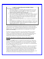
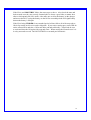
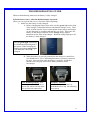
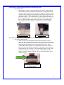
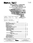
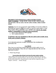
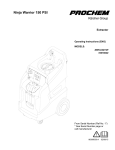
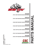
1
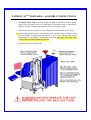
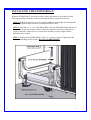
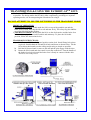
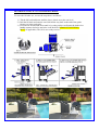
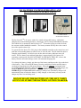
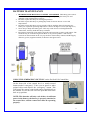
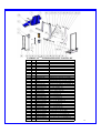
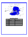
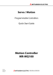
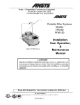
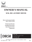
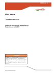
INSTALLATION AND OPERATING INSTRUCTIONS
PATRIOT-ATTM PORTABLE LIFT
PART NUMBER: F-12PPL-HD-AT1
U.S. PATENT NUMBER: 5,790,995
450 LB. [204 kg] MAXIMUM CAPACITY (PRO POOL LIFT)
MANDATORY – LEAVE THIS MANUAL WITH LIFT OWNER
9889 GARRYMORE LANE
MISSOULA, MT 59808
1-888-687-3552
FAX: 406-549-2602
WARNING
1.
2.
3.
4.
5.
6.
7.
8.
9.
IMPORTANT SAFETY INSTRUCTIONS
READ AND FOLLOW ALL INSTRUCTIONS. LIFT SAFETY CAN ONLY BE ENSURED IF THE
LIFT IS INSTALLED AND OPERATED PROPERLY – AS PER INSTRUCTIONS.
WARNING- TO REDUCE RISK OF INJURY, DO NOT PERMIT CHILDREN TO USE THIS
PRODUCT UNLESS THEY ARE CLOSELY SUPERVISED AT ALL TIMES.
WARNING- DO NOT PERMIT CHILDREN TO PLAY ON THIS PRODUCT.
WARNING- NEVER APPLY DIRECT WATER PRESSURE TO ELECTRONIC COMPONENTS.
WARNING – DO NOT OPERATE THIS LIFT IF THE DECK-TO-WATER DISTANCE IS OVER 12”.
WARNING – DO NOT OPERATE THIS LIFT UNDER LOAD IN A DRY POOL (NO WATER).
WARNING – DO NOT OPERATE THIS LIFT WITHOUT THE 10 WEIGHT-PLATES INSTALLED.
WARNING – FOR SAFETY REASONS YOU SHOULD NEVER SWIM ALONE!
SAVE A COPY OF THESE INSTRUCTIONS.
©AQUA CREEK PRODUCTS, 2012
JUNE 2012
PATRIOT-ATTM PORTABLE LIFT
TABLE OF CONTENTS
PAGE
DESCRIPTION
3
ADA INSTALLATION GUIDELINES
4
PATRIOT-ATTM PORTABLE PACKING LIST
5
PATRIOT-ATTM PORTABLE ASSEMBLY INSTRUCTIONS
6
FIXING-ANCHOR INSTALLATION INSTRUCTIONS
7
INSTALLING THE FIXING BOLT
8-9
TRANSPORTING & USING THE PATRIOT-ATTM PORTABLE
10
24V BATTERY OP & INSTALL INSTRUCTIONS
11
BATTERY MAINTENANCE
12
PRO POOL-ATTM LIFT OPERATING INSTRUCTIONS
13
CARE OF YOUR LIFT
14-17
TROUBLESHOOTING GUIDE
18
PATRIOT-ATTM INTEGRATED POOL LIFT: PARTS LIST
19
SEAT ASSEMBLY: PARTS LIST
20
PATRIOT-ATTM PORTABLE CART: PARTS LIST
21
WARRANTY
2
INSTALLATION: ADA GUIDELINES
ADA REQUIREMENTS:
The PATRIOT-ATTM portable lift is designed and manufactured to be 100% ADA compliant. But
for the installed lift to be 100% compliant the installation must meet the requirement for CLEAR
DECK SPACE as shown in the diagram to the left. To be compliant, install the lift at 16 inches
[406mm] minimum from the pool edge to the centerline of the seat, and make sure the deck has
the required CLEAR DECK SPACE as shown.
NOTE: As per ADA requirements the slope of the deck from the pool edge to the centerline
of the seat and within the clear deck space must be no greater than 1:48.
NOTE: The FIXING BOLT is used to fix the portable lift in place, and to ensure
that it remains in an ADA approved location. This makes the lift fully ADA
compliant to the latest revision.
3
THE PATRIOT-ATTM PORTABLE LIFT
WARNING
1. NEVER OPERATE THIS LIFT IF THE POOL DECK TO WATER
LEVEL EXCEEDS 9”
2. BEFORE OPERATING THE LIFT THE BALLAST TANK MUST BE
FILLED AS PER THESE INSTRUCTIONS. (SEE PAGE 5).
3. THE 24V BATTERY WILL ARRIVE UNCHARGED FOR SAFETY.
CHARGE THE BATTERY FOR 24 HOURS BEFORE INITIAL USE.
PARTS LIST: (SEE FIGURE 2)
1.
2.
3.
4.
5.
6.
PORTABLE CART W/ WHEELS
INTEGRATED LIFT/ROLL-BASE
BALLAST TANK W/ HANDLE
24V BATTERY
HANDSET CONTROL
BATTERY CHARGER
4
PATRIOT-ATTM PORTABLE - ASSEMBLY INSTRUCTIONS
1. The BALLAST TANK needs to be filled with sand to make the lift stable during
usage. This will require twelve (12) 50lb bags of all-purpose sand, or equivalently
600lbs [272kg] of medium-grain sand to fill to the required weight.
2. Remove the caps from each of the two filling holes on the BALLAST TANK.
3. Using a large funnel pour the sand into the tank. Alternate sides to keep the sand
even, and shake or tap the tank periodically to level it out. Fill the tank with at
least 600lbs of “all-purpose” or medium-grain sand. DO NOT USE THE LIFT
UNTIL THE TANK HAS BEEN FILLED!
4. Replace the caps to seal the tank.
5
FIXING-ANCHOR INSTALLATION INSTRUCTIONS:
TOOLS REQUIRED:
CORE-DRILLING RIG
1-1/4” DIAMETER CORE-DRILL
TAPE MEASURE
MARKING PEN
STEP 1] Use the diagram below to determine the location of the FIXING ANCHOR.
Make sure to allow for the clear deck space as shown.
STEP 2] Mark the location for the 1-1/4” x 4” deep anchor hole. Drill a ½” diameter, 4”
deep hole at the marked location.
STEP 3] Dry-fit the anchor-insert to make sure it fits flush with the deck surface.
STEP 4] Fill the hole ½ full with epoxy. Install the anchor insert flush with the deck
surface. Allow 24 hours for the epoxy to cure.
6
INSTALLING THE FIXING BOLT:
When the FIXING-BOLT is utilized to ensure proper placement of the portable lift the
following procedure should be used when placing the unit in position on the deck.
STEP 1: Roll the portable cart over the installed anchor. Look straight down through the
DOCKING BAR to align the anchor with the DOCKING BAR.
STEP 2: Drop the 1/2” x 4-1/2” DOCKING BOLT into the DOCKING BAR and start to
thread the bolt into the anchor by hand. Adjust the alignment until the bolt threads in a
couple of threads by hand. This is to ensure that the bolt is properly aligned before
threading with a wrench.
STEP 3: Tighten the DOCKING BOLT with a ¾” wrench or socket. Tighten until the
bolt is just touching the flat washer. DO NOT OVERTIGHTEN.
7
TRANSPORTING & USING THE PATRIOT-ATTM LIFT:
The Patriot-ATTM Lift has been designed to make transporting and using the lift as simple
as possible. The design makes the lift 100% ADA compliant by providing two separate
operating modes; one for transporting the lift and one for using it.
DO NOT ATTEMPT TO USE THE LIFT WHILE IN THE TRANSPORT MODE!
MODES OF OPERATION:
1] TRANSPORT MODE: In this mode the lift is on top of the portable cart and the
brake-foot is raised, allowing the lift to roll and turn freely. The safety flag also inhibits
use of the lift while in this position.
2] OPERATION MODE: In this mode the lift is on the deck surface and the brake-foot
is lowered, keeping the cart and lift stable and stationary. To place the lift in this
position, follow the instructions below.
TRANSPORT INSTRUCTIONS:
1) Roll Patriot-AT Lift to designated position on the deck. Install fixing-bolt (when
required). Stand behind the lift and tilt it back and down as shown below. Tilt the
lift to almost horizontal to make rolling and pivoting as simple as possible.
2) Roll the lift forward until it comes to the end and the pins engage with the slots.
3) Rotate the lift forward and down until it rests flat on the deck. Turn the handle of
the brake-foot clockwise until the brake-foot is firmly in contact with the deck.
The lift is now ready to use.
8
RETURNING THE LIFT TO TRANSPORT MODE:
To move the lift after use, reverse the steps above as follows:
1) Tilt the lift back and down until the lower wheels are at the cart level.
2) Roll the lift back and onto the cart. Roll all the way back to the end of the guide
frames (see close-up detail).
3) Pivot the lift forward and down until it is resting on the cart. Rotate the brake-foot
handle counter-clockwise and raise it off the deck. REMOVE THE FIXINGBOLT (if applicable). The lift is now ready to move.
9
24V BATTERY SYSTEM OPERATING AND
INSTALLATION INSTRUCTIONS
WALL MOUNT CHARGER
24V SEALED BATTERY
CONTROL BOX
& HANDSET REMOTE
The Pro Pool-ATTM Lift comes with a 24v sealed rechargeable battery, wall mount
charging unit (with mounting bracket), control box, and a waterproof handheld controller.
The control box is mounted to the Pro Pool-ATTM Lift and has a plug-in socket for both
the actuator and the handheld controller. The battery mounts directly above the control
box with a quick-release clip.
To operate the Pro Pool-ATTM Lift, plug in the handheld controller to the control box and
push the corresponding button to either lower or raise the unit. The lift should be able to
complete approximately 10-20 full cycles before the low battery indicator tone will
sound. The low battery tone indicates that there is approximately 20% battery life
remaining. At this point, DO NOT ATTEMPT TO OPERATE THE LIFT, remove the
battery from the unit and recharge on the wall mounted charging unit.
To recharge the battery, simply grip the top of the battery and depress the clip on the back
of the battery. This will unclip the battery from the control box bracket and the battery
can then be clipped into the wall mount charger. When the charger is plugged in the
green ON light will illuminate. When the battery is correctly mounted to the charger, the
orange CHARGE light will illuminate. When the battery is fully charged, the
CHARGE light will GO OFF and the battery is ready to use. The battery charger will
automatically shut off when the battery is fully charged, so the battery can stay on the
charger any time it is not being used.
DO NOT LEAVE THE BATTERY ON THE LIFT. WHEN
NOT IN USE STORE THE BATTERY ON THE CHARGER.
10
BATTERY MAINTENANCE
1. RECHARGE THE BATTERY AS OFTEN AS POSSIBLE. The battery power unit is
a sealed lead acid battery pack. Frequent recharges will prolong the battery life and
maintain a high cold amperage capacity.
2. Do NOT expose the battery to freezing temperatures.
3. Do NOT expose the battery to prolonged periods of extreme heat or severe cold
temperatures.
4. Do NOT expose the battery to long periods of direct sunlight. Heat will shorten your
battery life. Optimum operating temperature is below 20 degrees Celsius (68 degrees F.)
5. Never drop or bump the battery pack. This may result in loose or damaged internal
connections, and may bend the battery terminals.
6. Keep battery terminals clean and free from dirt and corrosion to ensure good contact. The
terminals may be cleaned using Scotch Brite or any similar product. Clean off any
corrosion or discoloration on the very top surfaces of the battery contacts and then apply
dielectric grease (supplied with lift) as shown in the figure below.
USING THE “EMERGENCY BUTTON” on the Pro Pool Lift Control Box
On the front side of the control box is a small recessed
button marked “emergency”. Take a pen or pencil or other
pointed object and depress the “emergency” button. This
will bypass the remote control and send a signal directly to
the actuator to raise the seat out of the pool and back to the
deck or up position.
NOTE: This function will only work if there is sufficient
power in the battery, the battery is properly attached to
the control box, and the control box must be operating
properly.
11
PRO POOL LIFT OPERATING INSTRUCTIONS:
NOTE: CHECK ALL NUTS & BOLTS FOR TIGHTNESS AND FOR
WORN PARTS BEFORE EACH USE. NEVER OPERATE THE LIFT
WITH THE ARMRESTS FLIPPED UP.
WARNING! FOR SAFETY REASONS YOU SHOULD NEVER SWIM ALONE!
The Pro Pool Lift TM should always be in the full up or deck position before a user
attempts to transfer into the chair. Before attempting to transfer into the chair, check to
make sure the lift is operating by making a short test run: move the chair at least part way
in and out of the pool.
As you are standing in front of the chair, facing the chair, the armrest on either side will
flip up to allow for easier lateral transfers. Transfer into the chair and then lower the flipup armrest back into its normal position. Secure the adjustable lap belt around the waist
so that the belt is snug, but not uncomfortably tight.
You are now seated comfortably in the Pro Pool Lift TM, and ready to move into the pool
or spa. Before you begin the operating cycle, take a visual check of the deck area and
pool area to make sure the operating path of the lift is clear.
It is not necessary to lower the lift all the way to the bottom of the lift’s stroke. You may
stop the lift at any time in the downward cycle when it is comfortable for you to exit the
chair into the water.
This is NOT true however, when returning to the deck during the up cycle. The lift
should always be cycled completely to the up or deck position before attempting to exit
the chair on the deck.
To lower the lift into the pool, simply apply pressure on the down arrow button on the
remote control handset and the chair will start to move towards the pool. NOTE: for
safety reasons, it is necessary to maintain continuous pressure on the control button. If
you take your finger off of the control button the lift will stop.
When you are sufficiently submerged into the water to allow for an easy exit from the
chair, you may stop the lift cycle by releasing pressure on the down arrow button on the
remote control handset. Now release the lap belt by grasping the end of the belt that is
protruding above the lap belt and tugging gently. You may now flip up the footrest to
create more room in front of the chair for you to exit. Exit the chair by sliding straight
forward until you are clear of the seat and the footrest.
When you are ready to return to the lift seat and exit the pool or spa, make sure that the
chair is lowered (submerged) sufficiently to allow you to easily slide into the chair. You
should not attempt to “lift” or raise yourself into the chair. Once you are reseated into the
chair, you may lower the footrest to it normal operating position and place your feet on
the footrest. Next, re-secure the adjustable lap belt snugly around your waist. To raise the
chair out of the pool, simply press on the up arrow button on the remote control handset
and apply continuous pressure until the lift chair comes to a rest on the deck in the full up
position. You may now release the lap belt and exit the chair.
12
SAFETY & MAINTENANCE INSTRUCTIONS
Do not play on or around this lift
1. Check the PATRIOT-ATTM LIFT before each use to assure there are no worn
parts and that all hardware is properly tightened. If there are any worn parts,
replace them BEFORE using the PATRIOT-ATTM LIFT. You can call our
customer service at 1-888-687-3552 to order any parts.
2. Aqua Creek Products, LLC lifts shall be grounded per local codes.
3. At least ONCE A WEEK, the PATRIOT-ATTM LIFT must be cleaned with fresh
water. Do not spray the PATRIOT-ATTM lifts’ control box or battery directly
with any pressure. Wipe all surfaces clean with a damp, non-abrasive cloth.
When cleaning the PATRIOT-ATTM LIFT, use non-abrasive soap and water.
Avoid harsh chemicals and disinfectants.
4. Always read the label instructions on any cleaner carefully before applying it to a
surface.
5. The WARNING & INTENDED USE labels on the PATRIOT-ATTM LIFT need
to be maintained in readable fashion. If they become unreadable or faded, please
replace the label immediately. Replacement labels are available from AQUA
CREEK PRODUCTS LLC. 1-888-687-3552.
CARE OF YOUR LIFT
Aqua Creek Pool Lift should not be stored in a pump room or in a storage room where
pool chemicals are kept. Storing the lift near pool chemicals may cause rusting and other
damage to occur. Your Aqua Creek stainless steel lift is powder coated to protect the
stainless steel from rusting. Most rusting will occur at weld points, crevices, under
gaskets, rivets or bolt heads.
The choice of a proper cleaning product is up to the consumer and there are many to
choose from. Depending on the type of cleaning and the degree of contamination
(rusting), some products are better than others. For routine cleaning the products most
recommended are gentle soaps or detergents or dilute mixtures of ammonia. For
stubborn spots and stains try using soft scrub with some brisk rubbing.
DO NOT USE POOL WATER TO CLEAN USE ONLY FRESH
WATER
If the lift is used DAILY make sure to wash the lift at the end of the day. Wash the lift
off using a mild soap and a soft cloth. Make sure to pay special attention to weld points
and crevices. Do not use a bristled brush or steel wool to clean the lift. Check that the
lift is working properly and then place the battery on the charger. It is recommended that
the battery be charged after every day of use.
If the lift is used WEEKLY follow the same steps as above. Also be sure to check all of
the contact points (terminals) for damage or corrosion. If you notice corrosion gently
clean the terminals. To clean corrosion from the terminals use a q-tip and some rubbing
alcohol. If the corrosion is particularly stubborn try using a 3M scotch brite pad, but be
careful not to damage the terminals. Apply dielectric grease to the terminals after
cleaning them. This will help to prevent further corrosion. Do not leave the battery on the
lift. Always store the battery on the charger whenever the lift is not being used.
13
If the lift is used MONTHLY follow the same steps as above. Also check the nuts and
bolts to make sure they are securely fastened (this is always a good idea, no matter how
often or infrequently the lift is used). Also make sure to store the battery on the charger
and not on the lift. Leaving the battery on the lift for extended periods will significantly
shorten the battery’s lifespan.
If the lift is being STORED for an extended period of time follow all of the steps above.
Check for rusting at all crevice and weld points. If you notice rusting spray some WD-40
on the affected area and take a 3M scotch brite pad and rub briskly. Afterwards be sure
to wash and rinse the lift again with soap and water. When storing the lift make sure it is
in a dry area and covered. DO NOT STORE in or around pool chemicals.
14
TROUBLESHOOTING GUIDE
Before troubleshooting make sure the battery is fully charged.
If the lift doesn’t move when the handset button is pressed:
When you can’t get the lift to move check the following things:
1. Make sure the battery is fully charged:
A. Before charging the battery first make sure the green light on the front
of the charger is illuminated (this means that the charger is on). Then
check to make sure the silver contact points on the battery and charger
are not damaged or corroded, and that they are clean. Then place the
battery on the charger and look for the orange charge light to
illuminate on the front of the charger. When the orange light goes off
the battery is fully charged.
The top green light will always
be illuminated indicating that it
has power. When charging the
battery the bottom orange light
will illuminate, until fully
charged.
B. When the battery is correctly installed on the charger or control box
you should hear a “click” indicating the battery is properly seated on
the unit. Also note that when the battery is properly seated there
should not be any gaps between the battery and the control
box/charger.
Not attached properly. Note
the white bracket is in front of
silver clip, which will not allow
for an electrical connection.
Properly Attached.
Note that the white bracket is
behind the silver clip. Not allowing
movement.
15
If the battery is fully charged and the lift is not moving then:
2. Check all cords:
A. Check that the cords are properly plugged in. Start by unplugging the
remote and the actuator cord from the control box. Once these cords
are removed check the ends for corrosion or damage. Plug the remote
cord back in by lining up the raised tab on the plug to the grooved line
on the control box outlet. Note that these cords require some force to
plug them in fully. You will know they a correctly inserted when you
here a “popping sound”. The cords will be recessed into the outlet. If
they are flush with the outside of the outlet they are not plugged in
fully and the lift will not function. Make sure you do this for both
cords.
NOT inserted fully.
Fully inserted.
If you have checked all the cords and the lift still doesn’t move:
3. Check the contact points:
A. After you have fully charged the battery and checked the cords to
make sure they are properly plugged in, check to make sure the contact
points are not corroded or bent. If the contact points are corroded take
some rubbing alcohol and a q-tip and clean off the points. After
cleaning the contact points it is recommended to put some dielectric
grease on the contact points (terminals) to help ensure good electrical
contact and prevent corrosion. Then reinstall the battery on top of the
control box. Make sure you hear a “click”, which indicates that the
battery is correctly seated. The lift will not work if the battery is not
seated correctly.
Silver tabs are the contact
(terminal) points.
16
If the lift stops moving over the water and is stuck:
4. Then try pushing the emergency button:
A. If the lift gets stuck out over the water use a pen or pencil tip and stick
it into the emergency button on the front of the control box to retract the
lift. Note the lift will not retract if the battery is not fully charged or if the
control box is not working. The emergency button only overrides the
remote in case it has gone bad. If this does not retract the lift then chances
are the remote is fine and you either have a problem with the battery, the
control box, or the cords are damaged or not plugged in properly.
Use a pen or pencil tip
to push in the small
black circle located next
to the word emergency,
on the front of the
control box.
17
PATRIOT-ATTM INTEGRATED LIFT: PARTS LIST
ITEM NO. QTY.
PART NUMBER
1
1 RAT-200-00
2
1 PPF-200-10
3
1 A-2012ARM-PS
4
1 A-2012SRS
5
1 L-2014FBL-PAT-R1
6
1 WM-A-8980PPAF-AT
7
1 SA-0904CA
8
1 SA-0904FRA
9
1 340461-00
10
1 CBJ2001NA001381
11
1 BAJ100000291
12
1 MBJ2-01
13
2 HOSE CLAMP, 1-3/4" SS
14
1 M5 X 10 LPCS, SS
15
2 BOLT1/4X1/2HEXSS
16
2 LOCKWASHER1/4SS
17
2 FLATWASHER1/4SS
18
1 SAFTEYPIN5/8X4
19
1 FLATWASHER5/16SS
20
1 NYLOCK5/1618SS
21
2 BOLT3/8X13/4SHLDRSS
22
2 FLATWASHER1/2SS
23
2 NYLOCK1/213SS
24
2 BOLT5/8X11/2HEXSS
25
1 BOLT5/8X6HEXSS CUS
26
2 FLATWASHER5/8SS
27
3 NYLOCK5/811SS
28
1 NYLOCK3/410SS
29
2 7/8X1/2X1/8TWBRNZ
30
2 11/8X5/8X1/8TWBRNZ
31
1 11/4X3/4X1/8TWBRNZ
32
2 3/4X1/2X1/4FBBRNZ
33
2 3/4X7/8X3/4FBBRNZ
34
1 11/8X3/4X1/4FBBRNZ
35
2 11/8X3/4X3/4FBBRNZ
DESCRIPTION
REBAL-AT ROLL-BASE ASSY
RANGER-AT FRAME ASSY
PORTABLE CHAIR ARM ASSY
PRO POOL SEAT SUPPORT
RANGER-AT CONTROL ARM
PRO POOL-AT ACTUATOR FRAME
18" CHAIR ASSEMBLY
FOOTREST ASSEMBLY
600mm ACTUATOR, PATRIOT
CONTROL BOX, PRO POOL & PATRIOT
24V BATTERY W/ACP LOGO
MOUNTING BRACKET (control box & battery)
HOSE CLAMP, 1-3/4" SS
M5 X 10mm LOW-PROFILE CAP SCREW, SS
1/4"-20 X 1/2" HEX BOLT, SS
1/4" LOCK WASHER, SS
1/4" FLAT WASHER, SS
5/8" X 4" SAFETY-CLIP PIN
5/16" FLAT WASHER, SS
5/16"-18 NYLOCK ,SS
3/8" X 1-3/4" SHOULDER BLT, SS
1/2" FLAT WASHER, SS
1/2"-13 NYLOCK, SS
5/8"-11 X 1-1/2" HEX BOLT, SS
5/8"-11 X 6" CUSTOM HEX BLT, SS
5/8" FLAT WASHER, SS
5/8"-11 NYLOCK NUT, SS
3/4"-11 NYLOCK NUT, SS
7/8" OD X 1/2" ID X 1/8" TW, BRNZ
1-1/8 OD X 5/8 ID X 1/8 TW, BRNZ
1-1/4 OD X 3/4 ID X 1/8 TW, BRNZ
3/4 OD X 1/2 ID X 1/4 FLNG BRNG, BZ
3/4 OD X 5/8 ID X 3/4 FLNG BRNG, BZ
1-1/8" OD X 3/4 ID X 1/4 FLNG BRNG, BZ
1-1/8" OD X 3/4 ID X 3/4 FLNG BRNG, BZ
18
SEAT ASSEMBLY: PARTS LIST
ITEM NO. QTY
PART NUMBER
1
1 P-900
2
1 P-1208HSB
3
2 P-2100ART
4
2 RUBBER FINGER GRIPS
5
1 F-38SB
6
1 SCREW#12X1PHSMS
7
1 PULLPIN&LANYARD
8
2 SCREW#12X1FHSMS
9
2 BOLT5/16X4HEXSS
10
4 FLATWASHER5/16SS
11
2 NYLOCK5/1618SS
DESCRIPTION
18" ROTOMOLDED CHAIR, GREY
HANDSET BRACKET, HDPE
ARMREST TUBE, 304 SS
RUBBER FINGER GRIP, BLACK
2" WIDE SEAT BELT, BLACK
#12 X 1" PAN-HD SHEET-MTL SCRW
1/4" PULL PIN & LANYARD
#12 X 1" FLAT-HEAD SCREW, SS
5/16"-18 X 4" HEX BOLT, SS
5/16" FLAT WASHER, SS
5/16"-18 NYLOCK NUT, SS
19
PATRIOT-ATTM PORTABLE CART: PARTS LIST
ITEM NO. QTY.
PART NUMBER
1
1 P-0138PBP-REVA2
2
1 RATWM-120-00
3
1 RATWM-130-10
4
1 P-985B
5
1 RAT-110-00
6
2 A-0138GFT-REVC
7
2 P-0138PCPS-REVB
8
1 P-0138PCPG-REVB
9
1 1942K76
10
1 65137574
11
2 2.03408.471
12
2 2.03456.471
13
2 2.03456.471BRK2
14
4 SCREW, #12 x 1" PHSMS
15
3 BOLT1/4X1/2BHCSSS
16
24 BOLT1/4X/12HEXSS
17
12 SETSCREW1/420X11/4
18
2 BOLT1/4X31/2HEXSS
19
27 LOCKWASHER1/4SS
20
31 FLATWASHER1/4SS
21
2 NYLOCK1/420SS
22
2 BOLT3/8X11/2HEXSS
23
10 BOLT3/8X21/2FHCSSS
24
2 BOLT3/8X3FHCSSS
25
14 FLATWASHER3/8SS
26
12 NYLOCK3/816HEXJAM
27
1 NYLOCK3/824SS
28
2 SQR-1-1/2-10-14
29
2 WWX-21 PLUG
30
1 REBELSAFETYFLAG
DESCRIPTION
PORTABLE CART BASEPLATE
PATRIOT-AT CART WLDMT A
PATRIOT-AT CART WLDMT B, 2-ANC
PATRIOT-AT BALLAST TANK/COVER
PATRIOT-AT CART TRAY
GUIDE FRAME ASSY, REVISION C
PORTABLE CART PLASTIC SLIDE
PORTABLE CART PLASTIC GUARD
PATRIOT BRAKE FOOT, 5/8"
BRAKE FOOT HANDLE, RND BLK
CASTER, SS FIXED 3-1/2"
CASTER, SS SWIVEL 3-1/2"
CASTER, SS W/BRAKE 3-1/2"
SCREW, #12 x 1" PAN-HD SHEET METAL
1/4"-20 X 1/2" BUTTON-HD CS, SS
1/4"-20 X 1/2" HEX BOLT, SS
SET SCREW, 1/4" X 1-1/4" 316-SS
1/4"-20 X 3-1/2" HEX BOLT, SS
1/4" LOCK WASHER, SS
1/4" FLAT WASHER, SS
1/4"-20 NYLOCK NUT
3/8"-16 X 1-1/2" HEX BOLT, SS
3/8"-16 X 2-1/2" FLAT-HD CS, SS
3/8"-16 X 3" FLAT-HD CS, SS
3/8" FLAT WASHER, SS
3/8"-16 NYLOCK HEX-JAM NUT, SS
3/8"-24 NYLOCK NUT, SS
1-1/2" SQ. BLACK PLUG, PLASTIC
WIDE-FLANGE CAP, YELLOW
REBEL SAFETY FLAG, RED
20
Aqua Creek Products, LLC Limited Warranty
Patriot-ATTM Portable Lift
Aqua Creek Products lifts have a Limited Lifetime Warranty on the frames, not including the powder coat finish.
Aqua Creek Products, LLC (a.k.a. Aqua Creek) also warrants to the original end user that all non-frame components
manufactured by Aqua Creek, when properly installed in accordance with assembly and installation instructions, and
properly used and maintained, shall be free from defects in material and workmanship for a period of four (4) years
from the date of original purchase, provided that Aqua Creek receives prompt notice in writing of any defect or
failure and satisfactory proof thereof, with the following exceptions:
This warranty specifically excludes reimbursement for labor to remove, repair, or install the product and any return
freight charges
These warranties do not cover any damages due to accident, misuse, abuse, negligence or failure to properly
maintain any products, or normal wear and tear from day to day operations. In the event that any products are
altered, repaired, or improperly installed or improperly used by anyone without the prior written approval by Aqua
Creek, all warranties are void. IMPORTANT: AMOUNT OF WEIGHT PLACED ON LIFT SHALL NOT
EXCEED THE RATED LIFTING CAPACITY OF 450 POUNDS [204 kg] FOR THE PATRIOT-AT PORTABLE
LIFT. NEVER OPERATE THE LIFT UNDER LOAD IN A DRY POOL (WITH NO WATER IN THE POOL).
To initiate a warranty claim, the owner of an Aqua Creek product must provide the place of purchase, in writing,
with a full description of the product, its serial number, the dates of purchase and installation, and the exact nature of
the defect. Within thirty (30) days after receipt of a written warranty claim by Aqua Creek, and barring any
unforeseen delays, the place of purchase will be notified of Aqua Creek’s decision regarding the claim.
If requested by Aqua Creek, any defective product must be returned, freight prepaid, to Aqua Creek’s designated
factory location or duly appointed distributor for inspection and/or repair. Aqua Creek will, at its option, repair or
replace the failed or defective item, and deliver the repaired product or replacement to the buyer of the product,
freight prepaid to the destination provided for in the original order. Products returned to Aqua Creek for which Aqua
Creek provides replacement under this limited warranty shall become the property of Aqua Creek.
A new warranty period shall NOT be established for the repaired or replaced products. Such products shall remain
under warranty only for the remainder of the original warranty period on the original products purchased.
This written limited warranty constitutes the final, complete and exclusive statement of warranty terms. No person
or organization is authorized to make any other specific or implied warranties or representations on behalf of Aqua
Creek.
THE WARRANTIES SET FORTH HEREIN ARE IN LIEU OF ALL OTHER WARRANTIES, EXPRESSED OR
IMPLIED, WHICH ARE HEREBY DISCLAIMED AND EXCLUDED, INCLUDING WITHOUT LIMITATION
ANY WARRANTY OF MERCHANTABILITY OR FITNESS FOR A PARTICULAR PURPOSE OR USE.
THE SOLE AND EXCLUSIVE REMEDIES FOR BREACH OF ANY AND ALL WARRANTIES WITH
RESPECT TO THE PRODUCTS SHALL BE LIMITED TO REPAIR OR REPLACEMENT AT AQUA CREEK’S
DESIGNATED FACTORY LOCATION, OR DULY APPOINTED DISTRIBUTOR, OR IN PLACE AT AQUA
CREEK’S OPTION. IN NO EVENT SHALL AQUA CREEK’S LIABILITY EXCEED THE ENTIRE AMOUNT
PAID TO AQUA CREEK BY THE ORIGINAL PURCHASER FOR THE FAILED OR DEFECTIVE PRODUCT.
IN NO EVENT SHALL AQUA CREEK PRODUCTS, LLC BE LIABLE FOR ANY INCIDENTAL,
CONSEQUENTIAL, SPECIAL, INDIRECT, PUNITIVE OR EXEMPLARY DAMAGES OR LOST PROFITS
FROM ANY BREACH OF THIS LIMITED WARRANTY OR OTHERWISE.
THIS WARRANTY GIVES YOU SPECIFIC LEGAL RIGHTS, AND YOU MAY ALSO HAVE OTHER RIGHTS,
WHICH MAY VARY FROM STATE TO STATE.
SOME STATES DO NOT ALLOW THE EXCLUSION OR LIMITATION OF INCIDENTAL, SPECIAL OR
CONSEQUENTIAL DAMAGES, SO SOME OF THE ABOVE LIMITATIONS OR EXCLUSIONS MAY
NOT APPLY TO YOU.
Aqua Creek Products
9889 Garrymore Lane
Missoula, MT 59808
21