1
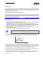
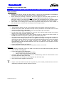
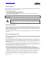
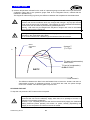
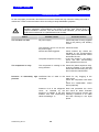
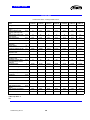
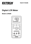
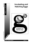
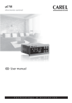
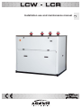
Installation use and maintenance manual
GB
LCW - LCR
TABLE OF CONTENTS
GENERALITIES
INSPECTION, CONVEYANCE, SITING
Inspection
Lifting and conveyance
Unpacking
Siting
INSTALLATION
Installation clearance requirements
General guidelines for plumbing connections
Water connection to the evaporator
Instructions for the filling up of the rank
Safety valve drain pipes
Electrical connections
Generalities
Remote controls
Split unit installation
STARTING UP
Preliminary checks
Starting up instructions
Starting operation
Checks during operation
Checking the refrigerant level
Stopping the unit
RG66001652_REV.02
2
LCW - LCR
TABLE OF CONTENTS
OPERATING LIMITS
Water flow to evaporator
Chilled water temperature
External water temperature
Operation with water at low temperatures
SETTING OPERATING PARAMETERS
Generalities
Maximum pressure switch
Minimum pressure switch
Service thermostat
Antifreeze thermostat
Anti-recycle timer
ROUTINE MAINTENANCE AND CHECKS
Warnings
Generalities
Repairing the cooling circuit
Tightness test
Hard vacuum and drying of cooling circuit
Charging with R407C refrigerant
Environmental protection
RETIRING THE UNIT
TROUBLESHOOTING
RG66001652_REV.02
3
LCW - LCR
Dichiarazione di conformità
La dichiarazione di conformità è allegata ad ogni macchina
Declaration of conformity
The declaration of conformity is attached to each unit sold.
RG66001652_REV.02
4
LCW - LCR
General Description
The Series
The LCW series of water-condensing chillers includes a range of models capable of satisfying every
need.
Water-condensing units – cooling only – of [ 53.9 - 296 kW ]
Heat pump reversible water-condensing units of [ 53 - 290 kW ]
Motor-driven evaporative units – cooling only – of [ 46.2 –257.3 kW ]
Structure
All LCW units have a galvanised sheet steel supporting base, coated with epoxy polyester powder paint
oven cured at 180°C and enclosing panels made of aluminium and magnesium alloy 5005 (Peraluman).
The unit features an exclusive design which lends it an attractive appearance as well as ensuring that all
components will be completely inaccessible when the unit is closed. This characteristic, together with the
extensive use of soundproofing material inside the compartment – an optional feature of low-noise
models – reduces noise to exceptionally low levels [Lp < 66 dB-A at 1 metre]. The plumbing/cooling
connections are situated at the top to reduce the technical spaces required for installation. All panels are
removable, thus enabling complete access to all chiller components, though only access from the front is
required for routine servicing.
Field of Application
The LCW units are designed to cool-heat water and solutions containing up to 30% glycol (percentage by
weight) in civil, industrial and technological air-conditioning systems. In buildings with large surface areas,
the air conditioning system can be expanded step by step as new floors or areas are sold/leased, by
installing an LCW unit for every floor in a small control room. This allows you to spread your investment
over time.. The possibility of keeping the evaporator indoors means there is no need to add glycol to the
water inside the system. In addition, you can keep all components requiring routine or special
maintenance in an easily accessible room. The plusses offered by these products are summed up in the
following table:
LCWC LCWH water-condensing units
o Occupies an extremely small surface area
o No need to add glycol to the water in the user circuit
o High COP [Coefficient of Performance] of the thermodynamical cycle
o No noise outside
o Extremely small refrigerant charge.
o Innovative aesthetics and total safety, given that the chillers are completely enclosed
o Option of installing an outdoor dry cooler where it is not possible to use a nonrecirculating water supply to cool the condenser
o Heat pump version with cycle reversibility at the cooling side
o Condensing control option on the heat pump versions possible
RG66001652_REV.02
5
LCW - LCR
LCRC versions with remote condenser
o Occupies an extremely small surface area
o No need to add glycol to the water in the user circuit
o Possibility of installing condensers on floors with a low weight-bearing capacity,
which would not be able to support the weight of a complete machine
o Simplified piping, since there is no need for vapour barrier insulation [cooling only
configuration]
o Innovative aesthetics and total safety, given that the chillers are completely enclosed
o Availability of a separate hydronic kit with the same styling as the chiller
o NOTE: for the units in question, it is mandatory to comply with the specifications of
97/23 PED, cited in the section "INSTALLATION"
LCW units are to be used within the operating limits stated in this manual; failure to comply with said
limits will invalidate the warranties provided in the contract of sale.
Cooling circuit
The entire cooling circuit is built in the manufacturer factory using only components of the finest quality
brands and processes conforming to the specifications of Directive 97/23 for brazing. The chillers are built
with a single cooling circuit using only components supplied by leading international manufacturers.
Compressors: only scroll-type compressors of leading international manufacturers are used in
the LCW units. The scroll compressor is presently the best solution in terms of reliability and
efficiency in the range of power up to 145 kW for each circuit and in terms of noise level.
NOTE: the scroll compressor, like all hermetic compressors, is classified as a pressure vessel
according to the PED insofar as its low-pressure section is concerned, to which the PS
indicated on the rating plate refers.
Heat exchangers all chillers have heat exchangers with braze-welded AISI 304 austenitic
stainless steel plates and connections made of AISI 304 L, characterised by a reduced
carbon content to facilitate brazing. Braze-welded plate exchangers represent the state of the
art in terms of heat exchange efficiency and make it possible to significantly reduce the
refrigerant charge compared to traditional solutions. The high turbulence induced by the
internal corrugation of the plates combined with their perfectly smooth surface also helps
prevent dirt build-up and the formation of scale on the condenser side. NOTE: due to the
presence of heat insulation, the data plate is not legible as required under 97/23 PED.
However, the exchanger serial number and declaration of conformity are recorded during
production and constitute an integral part of GALLETTI S.p.A records.
Cooling components:
o Molecular mesh activated-alumina filter dryer
o Flow indicator with humidity indicator. Indications are provided directly on the sight
glass.
o Thermostatic valve with external equalisation and integrated MOP function.
o Reverse cycle valve (heat pump only)
o Unidirectional valve (heat pump only)
o High and low pressure switches
o Schrader valves for checks and/or maintenance
o Safety valve
Electric control board: The electric control board is constructed and wired in accordance with
Directives 73/23/EEC and 89/336/EEC and related standards. The board may be accessed
through a door after the main switch has been put off. All the remote controls use 24 V
signals powered by an insulating transformer situated on the electric control board. A T
control kit comprising a thermostat and an auxiliary fan is available on request. The protection
rating of the unit is IP 43. NOTE: the mechanical safety devices such as the high pressure
switch are of the kind that trigger directly; their efficiency will not be affected by any faults
occurring in the microprocessor control circuit. in compliance with 97/23 PED.
RG66001652_REV.02
6
LCW - LCR
Control microprocessor: the microprocessor built into the unit allows the different operating
parameters to be controlled from a set of pushbuttons situated on the electric control board;
o Switching on/off of compressor to maintain the temperature set point of the chiller
inlet water temperature
o Alarm management
High / low pressure
Antifreeze
Flow switch
Pump alarm
o Alarm signalling
o Display of operating parameters
o Antifreeze protection of evaporator
o Management of maximum number of compressor start-ups
o RS232, RS485 serial output management (optional)
o Phase sequence error [Not displayed by the mP, but prevents the compressor from
starting up]
[ref. Microprocessor control manual for further details]
RG66001652_REV.02
7
LCW - LCR
BASIC COOLING CIRCUIT
Cooling only versions – Basic diagram of a single circuit
Plate heat exchanger
Scambiatore a piastre
Filter dryer
Filtro deidratore
Sight glass
Spia di flusso
Scroll compressor
Compressore scroll
Thermostatic valve
Valvola termostatica
Liquid receiver
Ricevitore di
liquido
Check valve
Valvola di non ritorno
4 way valve
Valvola inversione di
ciclo
RG66001652_REV.02
8
LCW - LCR
Heat pump versions – Basic diagram of a single circuit
Plate heat exchanger
Scambiatore a piastre
Filter dryer
Filtro deidratore
Sight glass
Spia di flusso
Scroll compressor
Compressore scroll
Thermostatic valve
Valvola termostatica
Liquid receiver
Ricevitore di
liquido
Check valve
Valvola di non ritorno
4 way valve
Valvola inversione di
ciclo
RG66001652_REV.02
9
LCW - LCR
Cooling only versions with remote condenser – Diagram of a single circuit
Plate heat exchanger
Scambiatore a piastre
Filter dryer
Filtro deidratore
Sight glass
Spia di flusso
Scroll compressor
Compressore scroll
Thermostatic valve
Valvola termostatica
Liquid receiver
Ricevitore di
liquido
Check valve
Valvola di non ritorno
4 way valve
Valvola inversione di
ciclo
RG66001652_REV.02
10
LCW - LCR
Heat pump versions with remote condenser – Basic diagram of a single circuit
Plate heat exchanger
Scambiatore a piastre
Filter dryer
Filtro deidratore
Sight glass
Spia di flusso
Scroll compressor
Compressore scroll
Thermostatic valve
Valvola termostatica
Liquid receiver
Ricevitore di
liquido
Check valve
Valvola di non ritorno
4 way valve
Valvola inversione di
ciclo
RG66001652_REV.02
11
Suction Liquid separator
Separatore liquido
LCW - LCR
Installation
General rules
- When installing or servicing the chiller, you must strictly follow the rules provided in this manual, comply
with the directions on the units and take all such precautions as are necessary.
- The fluids under pressure in the cooling circuit and the presence of electrical components may cause
hazardous situations during installation and maintenance work.
All work on the unit must be carried out by qualified personnel trained to do their
job in observance of current laws and regulations.
- Failure to comply with the rules provided in this manual or any modification made to the unit without
prior authorisation will result in the immediate invalidation of the warranty.
Warning: Before performing any kind of work on the unit, make sure it has been
disconnected from the power supply.
Inspection/Conveyance/Siting
Inspection on receipt
On receiving the unit, check that it is perfectly intact: the machine left the factory in perfect conditions;
immediately report any signs of damage to the carrier and note them on the Delivery Slip before signing
it.
GALLETTI S.p.A. or its Agent must be promptly notified of the entity of the damage. The Customer must
submit a written report describing every significant sign of damage.
Lifting and Conveyance
While the unit is being unloaded and positioned, utmost care must be taken to avoid abrupt or violent
manoeuvres. The unit must be handled carefully and gently: avoid using machine components as
anchorages when lifting or moving it.
The unit must be lifted using the holes provided on the base and a lifting beam to prevent the unit from
being deformed due to axial strains during lifting.
Warning: In all lifting operations make sure that the unit is securely anchored in order to
prevent accidental falls or overturning.
RG66001652_REV.02
12
LCW - LCR
Unpacking
The packing must be carefully removed to avoid the risk of damaging the unit. Different packing materials
are used: wood, cardboard, nylon etc.
It is recommended to keep them separately and deliver them to suitable waste disposal or recycling
facilities in order to minimise their environmental impact.
Siting
You should bear in mind the following aspects when choosing the best site for installing the unit and the
relative connections:
- size and origin of water pipes;
- location of power supply;
- accessibility for maintenance or repairs;
- solidity of the supporting surface;
All models belonging to the LCW series are designed and built for indoor installation As special care has
been taken in the sound insulation and sealing of the components and hot parts in general, they need not
be installed in dedicated rooms.
It is advisable to place a rigid rubber strip between the base frame and the supporting surface.
INSTALLATION
Installation clearance requirements
In the case of units with a remote condenser, the plumbing and cooling connections are provided on the
top of the unit. This allows the chiller to be placed practically against the rear wall. It is nonetheless of
fundamental importance to assure the following service spaces:
-
back side min. 0 metres
electric control board side: min. 1.0 metre to guarantee access for inspection and/or
maintenance of cooling components
lateral part min. 0.5 metre for extraordinary maintenance
top side: min. 1.0 metre for adequate connection to the external hydraulic and cooling piping.
RG66001652_REV.02
13
LCW - LCR
General Guidelines for Plumbing Connections
When you are getting ready to set up the water circuit for the evaporator you should follow the directions
below and in any case make sure you comply with national or local regulations (use the diagrams
included in this manual as your reference).
- Connect the pipes to the chiller using flexible couplings to prevent the transmission of vibrations and
to compensate thermal expansions. For the types and size of the water and cooling connections
[versions with remote condenser only] refer to the table of technical data.
- Install the following components on the pipes:
• temperature and pressure indicators for routine maintenance and monitoring of the unit. Checking
the pressure on the water side will enable you to verify whether the expansion tank is working
efficiently and to promptly detect any water leaks within the equipment.
• traps on incoming and outgoing pipes for temperature measurements, which can provide a direct
reading of the operating temperatures. Temperature readings can in any case be obtained from the
microprocessor installed on the unit.
• regulating valves (gate valves) for isolating the unit from the water circuit during maintenance work.
• OBLIGATORY metal mesh filter (incoming pipes), with a mesh not to exceed 1 mm, to protect the
exchanger from scale or impurities present in the pipes. This prescription is particularly important at
first start-up.
• air vent valves, to be placed at the highest points of the water circuit for the purpose of bleeding air.
[The internal pipes of the unit are fitted with small manual air vent valves for bleeding the unit itself:
this operation may only be carried out when the unit is disconnected from the power supply].
• drainage valve and, where necessary, a drainage tank for emptying out the equipment for
maintenance purposes or when the unit is taken out of service at the end of the season.
Water connection to the evaporator
It is of fundamental importance that the incoming water supply is hooked up to the
connection marked “Water Inlet”
Otherwise the evaporator would be exposed to the risk of freezing since the antifreeze thermostat would
not be able to perform its function; moreover the reverse cycle would not be respected in the cooling
mode, resulting in additional risks of malfunctioning This position does not enable the operation of the
water flow control device.
The dimensions and position of plumbing connections are shown in the dimension tables at the end of
the manual.
The water circuit must be set up in such a way as to guarantee that the nominal flow rate
of the water supplied to the evaporator remains constant (+/- 15%) in all operating
conditions.
RG66001652_REV.02
14
LCW - LCR
The compressors work intermittently, since the chilling requirements of the user generally do not coincide
with the compressor output. In systems containing little water, where the thermal inertia of the water is
lower, it is a good idea to check that the water content in the section delivering to users satisfies the
condition below:
V =
V
Sh
ρ
Dτ
DT
Cc
Ns
Cc × Δτ
ρ × Sh × ΔΤ × Ns
= water content in user section
= specific heat of the fluid
= fluid density
= minimum time lapse between 2 compressor restarts
= allowed water T differential
= Cooling capacity
= N° of capacity control steps
[m3]
[J/(kg/°C)]
[kg/m3]
[s]
[°C]
[W]
Tank
Ts
Q; TW in
RG66001652_REV.02
Q; TW out
15
LCW - LCR
A standard feature of LCW units is a device for controlling the flow rate (flow switch or
differential pressure switch) in the water circuit in the immediate vicinity of the evaporator.
Any tampering with said device will immediately invalidate the warranty.
It is OBLIGATORY to install a metal mesh filter on the inlet water pipe.
Warning: When making the plumbing connections. make sure there are no open flames
in proximity to or inside the unit.
INSTRUCTIONS FOR THE FILLING UP OF THE TANK
The tank is not planned to resist to a depression greater than -0,15 Bar, so pay
attention to the fact that the suction pressure of the pump, where the expansion
tank is positioned, has to be always greater than 0,5 Bar with the pump in
operation: this fact also contributes to reduce any risks concerning the cavitation
of the pump.
It is of fundamental importance for the installer to follow and check the instructions written below
stepwise, so as to avoid every kind of risks concerning the implosion of the tank or the cavitation of the
pump:
a) Empty the expansion tank until the pressure is 0,5 Bar
b) Charge the system and pressurize it until about + 1 Bar in suction, pump side (with pump not
working)
c) Allow air to escape from the system
d) Check the suction pressure of the pump (about 1 Bar) and start the system
Stop the pump after 15-30 minutes and repeat from point c) until you don’t hear noises, caused by air still
present in the system, anymore.
General guidelines for Cooling connections of LCR units
LCR units are supplied pre-charged with inert nitrogen gas at a pressure of 3 bars to protect them from
the penetration of humidity and are provided with threaded Rotalock weld-on connections (3 pieces) for
outdoor piping.
Rotalock
Connection
Braze-welded copper
connection
Piping made on site
RG66001652_REV.02
16
LCW - LCR
Note: Only qualified personnel may choose and install the piping and carry out the final
braze-welding operations, as per current laws and regulations. Said personnel must
issue a new declaration of conformity for units assembled on site.
RG66001652_REV.02
17
LCW - LCR
The following table reports the dimensions suggested for piping
Unit model
Fluid line
Thickness (mm)
GAS line
Thickness (mm)
LCRC0502-0672
LCRC0742-1362
LCRC1522-2442
LCRC2582-3042
16 mm
18 mm
22 mm
28 mm
1
1
1,5
1,5
22
28
35
42
1,5
1,5
1,5
1,5
Prescriptions for laying
Vertical ascending gas lines set a trap every 4 metres
Vertical fluid lines:
o The complete miscibility between oil and
refrigerant
assures
entrainment
of
lubricant in all conditions
o Pay attention to the fact that in the case of
descending lines the pressure generated
by the column of liquid is added to the
outlet pressure: for differences in level
exceeding 10 m contact the manufacturer
to have the safety pressure switches set
accordingly
o Pay attention to the fact that in the case of
rising lines, the pressure drop due to the
travel height reduces the undercooling of
the liquid, resulting in the possible
formation of flash vapours: in this case
choose a larger sized remote condenser
and charge until you obtain 2°C of
additional undercooling for every 10 m of
height.
3xD
D
The table below shows the classification of piping according to EEC directive 97/23 PED
Outside
diameter
[mm]
10
12
16
18
22
28
35
42
54
Thickness
(mm)
PS
bars
PED
Category
σs copper
[N/mm2]
actual σ
[N/mm2]
Coeff. Sic.
1
1
1
1
1,5
1,5
1,5
1,5
1.5
28
28
28
28
28
28
28
28
28
A3 P3
A3 P3
A3 P3
A3 P3
A3 P3
A3 P3
A3 P3
CAT I
CAT I
227
227
227
227
227
227
227
227
227
11.2
14
19.6
21
17.3
23.3
28.9
36.4
47.6
20.3
16.2
11.6
10.8
13.1
9.8
7.85
6.2
4.8
Note: The material used for the piping must be exclusively CU-DHP or CW024A. copper of
a quality complying with the specifications of standard EN12735 and for which materials
certificate 3.1b is available.
RG66001652_REV.02
18
LCW - LCR
.
Evacuation and charging operations for LCR-type units
This type of work must be carried out by qualified personnel trained to do their job
in observance of current laws and regulations
1. Introduction:
The simultaneous presence of liquid and vapour makes it necessary for both to be in a state of saturation [ Gibbs
law ], as shown in fig. 1). In conditions of thermal equilibrium, the pressure in the tank corresponds to the T of the
surrounding environment; a withdrawal of refrigerant charge will cause pressure drops, which will be associated
with
- withdrawal of refrigerant charge
- pressure drop in tank
- T drop - change of state
- cooling of liquid
pressure drop in tank
T drop - change of state
evaporation of part of the liquid, causing the liquid itself to
cool
thermal exchange with ambient air, further evaporation of
remaining liquid; the original pressure is restored in the tank
after a certain amount of time
Tank/ambient T
P
Fig. 1
Saturated
Gas
Saturated
liquid
Heat content h
RG66001652_REV.02
19
LCW - LCR
2. Vacuum and charging machine
Tank
Charging gun
Cock
Fig. 2
Solenoid
valve
Charging machine
Charging
piston
Volumetric Flow
Rate Gauge
The charging piston compresses the refrigerant to a max P of 20 bar-r, thus favouring the re-condensation of any
flash vapour that may have formed during transit through the line between the tank -cylinder: consider fig. 1) in
which the saturated liquid (left-hand point on curve) undergoing slight pressure drops "enters" into the tank
generating flash vapour and ultimately a liquid-vapour mixture.
Opening the solenoid valve of the charging machine allows the passage of refrigerant liquid toward the charging
gun and flow is measured by the volumetric flow rate gauge; the quantity in weight is calculated by measuring the
T of the liquid, calculating its density (tables) and multiplying this value by the volumetric flow rate.
Given the constant pressure in the charging machine cylinder, the flow rate of the refrigerant mainly depends on
the cross section area of the charging nozzle and must be dimensioned so as to limit, in our case, the charging
speed to 2 kg per minute.
RG66001652_REV.02
20
LCW - LCR
3. Vacuum cycle
In general it is preferable to apply a “long” rather than “hard” vacuum: reaching low pressures too abruptly may in
fact cause any trapped humidity to evaporate instantaneously, thereby freezing part of it.
Fig. 3
P [Pa]
150
6
200 s
Time
The figure represents a vacuum cycle and an optimal subsequent pressure rise for the refrigeration devices we
manufacture.
As a rule, if there is suspicion of an extensive presence of humidity throughout the circuit or system as a whole,
the vacuum must be “broken” with anhydrous nitrogen and then the steps must be repeated as described; this
operation facilitates the removal of trapped and/or frozen humidity during the evacuation process.
4. Evacuating a circuit “contaminated” with refrigerant
The first step is to remove the refrigerant from the circuit using a specific machine with a dry compressor for
recovering the refrigerant.
Refrigerants all tend to dissolve in oil [compressor sump] in percentages that are directly proportional to increases
in pressure and decreases in the T of the oil itself - Charles' Law -
Oil T
Pressure
T3
T2
T1
% of R.... in oil
The release of refrigerant tends to cool the oil and thus actually serves to oppose the release itself: for this
reason, it is advisable to switch on the crankcase heating elements, if available, during the evacuation process.
If a high % of refrigerant comes into contact with the Pirani gauge (vacuum sensor), it may “drug” the sensitive
element of the latter. rendering it inefficient for a certain period of time. For this reason. if no machine for
recovering refrigerant is available. it is nonetheless advisable to switch on the crankcase heating elements and
avoid applying a vacuum until the circuit has been adequately purged of refrigerant: the refrigerant may in fact
solubilise in the oil of the vacuum pump. undermining its performance for a long time (hours).
5. Charging positions [single point]
RG66001652_REV.02
21
LCW - LCR
The best position for charging the air conditioners is the section between the thermostatic valve and the
evaporator; care should be taken to avoid fixing the thermostat bulb until the operation is complete. This is
important to ensure that the valve orifice remains open so as to allow the passage of refrigerant also toward the
condenser/receiver.
Air-condensing water chillers should be charged with refrigerant in the section between the condenser and
thermostatic valve, this favours flow into the larger-sized exchanger.
If possible, avoid the inflow of refrigerant into the compressor as this may cause excessive dilution of the
lubricant; in any case. first check the compatibility between the crankcase capacity and the required charge
volumes.
Safety valve drain pipes
A safety valve is present on the refrigerant circuit. Some regulations provide that the refrigerant drained
from the valves be conveyed to the outside by means of a suitable pipe with a diameter at least matching
that of the valve drainage outlet; the valve must not be made to bear the weight of the pipe.
The valves positioned on the compressor outlet only discharge hot saturated gas; those on the liquid
receivers, may discharge saturated liquid and pose a greater hazard of burns due to the strong
dehydrating effect caused by the sudden evaporation of refrigerant fluid in contact with bodies having a T
> -41 °C.
Warning: Always direct the drain pipe toward an area where the discharge cannot harm
people.
RG66001652_REV.02
22
LCW - LCR
ELECTRICAL CONNECTIONS
GENERALITIES
Before carrying out any job on electrical parts, make sure the power supply is
disconnected.
Check that the mains electricity supply is compatible with the specifications (voltage, number of phases,
frequency) shown on the unit rating plate.
The power connection for single-phase loads is to be made with a three-pole cable and “N” wire at the
centre of the star [optional: power supply w/o neutral].
The size of the cable and line protections must conform to the specifications provided in
the wiring diagram.
The supply voltage may not undergo fluctuations exceeding ±5% and the unbalance between phases
must always be below 2%.
The above operating conditions must always be complied with: failure to ensure said
conditions will result in the immediate invalidation of the warranty.
The electrical connections must be made in accordance with the information shown in the wiring diagram
provided with the unit and current regulations.
An earth connection is mandatory. The installer must connect the earthing wire using the earthing
terminal situated on the electric control board (yellow and green wire).
The power supply to the control circuit is shunted from the power line through an insulating transformer
situated on the electric control board.
The control circuit is protected by suitable fuses or automatic breakers depending on the unit size.
Electrical connections of circulation pump
For all LCW units a clean contact is provided on the electric board for powering a low-voltage remote
control used to start the pump.
If it is an integral part of the supply, the pump must be started before the chiller and
stopped after the latter (minimum recommended delay: 60 seconds). If it is connected to
the terminal in the electric control board, this function is carried out by the built-in
microprocessor.
RG66001652_REV.02
23
LCW - LCR
Remote controls
If you wish to include a remote control for switching the unit on and off, you must remove the bridge
between the contacts indicated in the wiring diagram and connect the remote ON/OFF control to the
terminals themselves [see annexed wiring diagram], then enable the "REMOTE" function by means of
the switch provided in the electric board.
Summer Winter Remote Switching (Heat pump version)
If you wish to include a remote control for summer/winter switching of the unit, you must remove the
bridge between the contacts indicated in the wiring diagram and connect the remote ON/OFF control to
the terminals themselves [see annexed wiring diagram], then enable the "REMOTE" function by means
of the switch provided in the electric board.
STARTING UP
Preliminary checks
-
-
Check that the cocks of cooling circuit (if present) are open.
Check that the electrical connections have been made properly and that all the terminals are
securely tightened. This check should also be included in a periodic six-month inspection.
Check that the voltage at the RST terminals is 400 V ± 5% and make sure the yellow indicator light
of the phase sequence relay is on. The phase sequence relay is positioned on the electric control
board; if the sequence is not duly observed, it will not enable the machine to start.
Make sure there are no refrigerant leaks that may have been caused by accidental impacts during
transport and/or installation.
Check the power supply to the crankcase heating elements, where present.
The heating elements must be turned on at least 12 hours before the unit is started.
This function is carried out automatically when the main switch is off. Their function is
to raise the T of the oil in the sump and limit the quantity of refrigerant dissolved in it.
To verify whether the heating elements are working properly, check the lower part of the compressors:
it should be warm or in any case at a temperature 10 - 15 °C higher than the ambient temperature.
Pressure
Oil T
% of R407C in oil
The diagram above illustrates a specific property [Charles’ Law] of gases. which are more soluble in
liquids as the pressure increases but less soluble as the temperature increases: if the oil in the sump is
held at a constant pressure, an increase in oil temperature will significantly reduce the amount of
refrigerant dissolved in it, thus ensuring that the lubricating function desired is maintained.
- Check that the plumbing connections have been properly made according to the indications given on
the plates to be found on the unit itself (proper inlet and outlet connections).
- Make sure that the water circuit is duly bled to completely eliminate the presence of air: load the circuit
gradually and open the air vent valves on the top part, which the installer should have set in place.
RG66001652_REV.02
24
LCW - LCR
STARTING UP FOR THE FIRST TIME
HOW TO START UP THE Chillers OF THE LCW SERIES FOR THE FIRST TIME
Water connections
•
•
•
Warning: the chiller is charged with HFC R407C – Group I EN 378 refrigerant (non-hazardous
substances) conforming to the requirements of EEC regulation 2037/00.
When making the plumbing connections, be sure to apply the inlet and outlet connections as
indicated. In particular, be very careful not to invert condenser and evaporator circuits.
Apply gate valves on the water side so that the chiller may be isolated from the plumbing system
and install a mesh filter (accessible for inspection) on both the evaporator and condenser sides.
Fill the water circuit, making sure to expel all the air present inside using the air valve situated on
the external brass connections at the top right of the storage reservoir.
Electrical connections
•
•
•
•
•
•
•
•
Put on the main switch, turn the ½-turn locking screws of the electric enclosure and open it.
Introduce the power cable 400/3/50+N through the hole provided on the left side of the unit and
secure it in place with the cable holder.
Connect the power supply and earthing wire to the terminals of the main switch.
Put off switch “QF” of the compressor so as to be sure it will not start running in the wrong
direction in the case of a phase sequence error.
Position the Local/Remote selector (SLR) situated at the top middle of the electric board on
LOCAL and switch on the power by turning the main switch (IG) to ON.
Check the phase sequence relay situated in the middle of the electric control board to make sure
the phases are in the right sequence R-S-T; the green indicator light should go on: if it does not,
disconnect the power supply to the unit from the external distribution board, invert two phases
and repeat the check. IN NO CASE SHOULD YOU TAMPER WITH THE WIRING
DOWNSTREAM FROM THE MAIN SWITCH since this may alter the correct sequence of other
devices, e.g. pump(s).
Put the compressor switch “QF” back on.
Close the electric control board and lock it by means of the ½- turn locks.
Starting up
• Check that all external cocks of the water circuit are open and water flows properly (the flow
alarm should not be triggered)
• Put the main switch on the ON position.
o The [external] pump will start immediately.
o After 60 seconds the compressor will start
• Check the water thermal differential (12-7°C to be detected by means of a thermometer on the
inlet and outlet water pipes of the unit).
• Check that there are no leaks on the refrigerant side and water side.
• Using all the screws supplied, close the unit.
Use
•
always consult the USER manual and the μChiller or pCO1 manual provided with the unit when
undertaking maintenance and/or advanced set-ups.
RG66001652_REV.02
25
LCW - LCR
STARTING OPERATION
Before starting the unit, turn the main switch on, select the operating mode desired from the control panel
and press the "ON" button on the control panel.
The unit will start up if enabled:
- by the safety devices of the water circulation pump/s
- by the flow switch (or differential pressure switch)
- by the T sensor measuring the temperature of the water returning from the system [chiller inlet]
- and no alarms have been triggered
If the unit fails to start up, check whether the service thermostat has been set according to the nominal
values provided
You should not disconnect the unit from the power supply during periods when it is
inoperative but only when it is to be taken out of service for a prolonged period (e.g. at
the end of the season). To turn off the unit temporarily follow the directions provided in
the section 4.5.
CHECKS DURING OPERATION
- Check the phase sequence relay on the control board to verify whether the phases occur in the correct
sequence: if they do not, disconnect the unit from power supply and invert two phases of the incoming
three-pole cable. Never attempt to modify internal electrical connections: any undue modifications will
render the warranty null and void.
- Check that the temperature of the water entering the evaporator is close to the value set on the service
thermostat.
CHECKING THE REFRIGERANT LEVEL
- After a few hours of operation, check whether the liquid level indicator has a green crown: a yellow
colour indicates the presence of humidity in the circuit. In such a case the circuit must be dehumidified
by qualified personnel.
- Large quantities of bubbles should not appear through the liquid level indicator. A constant passage of
numerous bubbles may indicate that the refrigerant level is low and needs to be topped up. The
presence of a few bubbles is however allowed, especially in the case of high-glide ternary mixtures
such as HFC R407C.
- Also check that the end-of-evaporation temperature shown on the pressure gauge (refer to the
pressure gauge scale for the refrigerant R407C, marked with the initials D.P. - Dew Point) is about 4°C
lower than the temperature of the water leaving the evaporator.
- Make sure the overheating of the cooling fluid is limited to between 5 and 8 °C. To this end:
1) read the temperature indicated by a contact thermometer placed on the compressor intake pipe;
2) read the temperature indicated on the scale of a pressure gauge likewise connected to the intake
side; refer to the pressure gauge scale for the refrigerant R407C, marked with the initials D.P. (Dew
Point).
The degree of overheating is given by the difference between the temperatures thus determined.
- Make sure that the undercooling of the cooling fluid is limited to between 3 and 5°C. To this end:
1) read the temperature indicated by a contact thermometer placed on the condenser outlet pipe;
RG66001652_REV.02
26
LCW - LCR
2) read the temperature indicated on the scale of a pressure gauge connected to the liquid inlet at the
condenser outlet; refer to the pressure gauge scale for the refrigerant R407C, marked with the
initials B.P. (Bubble Point).
The degree of undercooling is given by the difference between the temperatures thus determined.
Warning: all units of the LCW series are charged with R407C refrigerant except the
versions with remote condenser which are charged with nitrogen. Any top-ups must be
made using the same type of refrigerant. This operation is to be considered extraordinary
maintenance work and must be performed by qualified personnel.
Warning: LCR units are pre-charged with anhydrous nitrogen and must be evacuated
before charging with the refrigerant.
Warning: the refrigerant R407C requires “POE” polyolester oil of the type and viscosity
indicated on the compressor rating plate.
For no reason should oil of a different type be introduced into the oil circuit.
Real P
compressor
outlet
Average T
(T1+T2)/2
P
T1 (start of condensation)
DEW POINT
T2 (end of condensation)
BUBBLE POINT
R407C
Heat content h
-
The difference between the Dew Point and Bubble Point is known as “GLIDE” and this is a
characteristic property of refrigerant mixtures. If pure fluids are used, the phase change
occurs at a constant T and thus the glide is equal to zero.
STOPPING THE UNIT
To stop the unit press the "OFF" button on the front panel.
Warning: do not stop the unit using the main switch. The latter device is used to
disconnect the unit from the electricity supply when there is no passage of current, i.e.
when the unit is already turned OFF.
Moreover, if you completely disconnect the unit from the electricity supply, the crankcase
heating elements (where present) will receive no power, thereby jeopardising the
integrity of the compressor the next time the unit is started.
RG66001652_REV.02
27
LCW - LCR
OPERATING LIMITS
Operating limits of LCW chillers in relation to the outlet water temperature and water dew point.
Applications with water T above the specified limits require the use of R134a refrigerant fluid. For details
please contact the local Galletti dealer.
Cooling only Units
Water temperature
Minimum
Maximum
Notes
10
25
25
45
Without antifreeze products
Below
25°C
the
condensation
pressure
control is required
Minimum
Maximum
Notes
Evaporator inlet (cooling
mode)
Condenser inlet (cooling
mode)
10
25
Without antifreeze products
25
45
Evaporator
inlet
(heating mode)
Condenser
inlet
(heating mode)
(*)
25
45
Below
25°C
the
condensation
pressure
control is required
Without antifreeze products
(*)
12
25
Evaporator inlet
Condenser inlet
Heat pump units
Water temperature
(*) in heat pump operation heat exchangers work on reverse function.
Cooling only units with remote condenser
Water temperature
Minimum
Maximum
Notes
10
40
25
65
Without antifreeze products
Below
40°C
the
condensation
pressure
control is required
Minimum
Maximum
Notes
Evaporator inlet (cooling
mode)
Dew point (cooling mode)
10
25
Without antifreeze products
40
65
Evaporator
inlet
(*)
(heating mode)
Evaporation temperature
(heating mode)
25
45
Below
40°C
the
condensation
pressure
control is required
Without antifreeze products
-15
15
Evaporator inlet
Dew Point (°C)
Heat pump units with remote condenser
Water temperature
(*) in heat pump operation heat exchangers work on reverse function.
RG66001652_REV.02
28
LCW - LCR
Glycol solutions
It is possible to produce water at temperatures below 5°C and as low as -10°C using glycol solutions that
lower the freezing point according to the following table:
Minimum temperature of water produced
5 °C
2°C
-1 °C
-5°C
-10 °C
Percentage of ethylene glycol (in weight)
0%
10 %
15%
25 %
30 %
Freezing temperature of mixture °C
0 °C
-4 °C
-8 °C
-14 °C
-18 °C
Given an equal volumetric flow rate of water, pressure drops will depend on the percentage of glycol, as
shown in the following table:
Percentage of ethylene glycol (in weight)
0%
10 %
15%
25 %
30 %
Pressure drop change
0%
+12 %
+ 21 %
+43 %
+55 %
Operating limit table
thermal carrier fluid water or water/antifreeze mixtures
maximum water operating pressure 6 bars
Maximum operating P – High pressure side
= 28 bar-r
Maximum operating T – High pressure side
= 125° C
Maximum operating T - indoor environment
= 50°C
Minimum operating T
= -10°C
Maximum operating P – Low pressure side
= 22.6 bar-r
Supply voltage +/- 10% of rating plate voltage
Maximum stocking T
= + 50 °C
Minimum stocking T
= - 10 °C (limit imposed by the built-in electronic
components)
(*) this value can be reached only in storage conditions and determines the refrigerant saturation
pressure of 22 bar-r on the low pressure side of the circuit, a value which in fact defines the limits.
Water flow to evaporator
The nominal flow rate is based on a thermal differential of 5° C between inlet and outlet water, in relation
to the cooling capacity provided at the nominal water temperatures (12/7 °C).
The maximum allowed flow rate is associated with a thermal differential of 3 °C. Higher flow rate values
cause too big pressure drops.
The minimum allowed flow rate is associated with a thermal differential of 8 °C. Lower flow rates could
cause excessively low evaporation temperatures, which would trigger the safety devices and cause the
unit to stop.
RG66001652_REV.02
29
LCW - LCR
SETTING OPERATING PARAMETERS
GENERALITIES
All the control devices are set and tested in the factory before the unit is dispatched. However, after the
unit has been in service for a reasonable period of time you can perform a check on the operating and
safety devices. The settings are shown in Tables II and III.
All servicing of the equipment is to be considered extraordinary maintenance and
may be carried out SOLELY BY QUALIFIED TECHNICIANS: incorrect settings may
cause serious damage to the unit and injury to persons.
The operating parameters and control system settings configurable by means of the microprocessor
control are password protected if they have a potential impact on the integrity of the unit.
TABLE II - SETTING OF CONTROL DEVICES
CONTROL DEVICE
Service thermostat [Cooling]
Service thermostat [H]
SET POINT
DIFFERENTIAL
12
40
2
2
°C
°C
TABLE III - SETTING OF SAFETY - CONTROL DEVICES
CONTROL DEVICE
Antifreeze thermostat
Maximum pressure switch IV PED
High pressure relief valve IV PED
Minimum pressure switch
Modulating condensation control
device [optional]
Time lapse between two starts of
the same compressor
Delay in flow switch alarm
Delay in low pressure alarm
RG66001652_REV.02
ACTIVATION
DIFFERENTIAL
RESETTING
°C
bars
bars
bars
bars
+4
28,0
29,0
2
14
2
4
1.5
7
Automatic
Manual
Automatic
s
360
-
-
s
s
20
120
-
-
30
LCW - LCR
MAXIMUM PRESSURE SWITCH
The high pressure switch stops the compressor when the outlet pressure exceeds the set value.
Warning: do not attempt to change the setting of the maximum pressure switch. Should
the latter fail to trip in the event of a pressure increase, the pressure relief valve will
open.
The high pressure switch must be manually reset; this is possible only when the pressure falls below the
set differential (see Table III).
MINIMUM PRESSURE SWITCH
The low pressure switch stops the compressor when the intake pressure falls below the set value for
more than 120 seconds.
The switch is automatically reset when the pressure rises above the set differential (see Table III).
SERVICE THERMOSTAT
This device permits to enable and disable the compressors' operation as a function of the reading of the
inlet water temperature of the chilling unit [return from the system]. For further details, refer to the
microprocessor control section in the manual.
ANTIFREEZE THERMOSTAT
The antifreeze probe is located at the evaporator outlet and stops the compressor when the temperature
goes below the set limit value. Together with the flow switch and low pressure switch, this device protects
the evaporator from the risk of freezing as a result of faults in the water circuit. For further details, refer to
the microprocessor control section in the manual.
ANTI-RECYCLE TIMER
The function of the timer is to prevent excessively frequent compressor starts and stops. This device
imposes a minimum time lapse of 480 seconds between two compressor starts. For further details. refer
to the microprocessor control section in the manual.
Never attempt to change the delay set in the factory: wrong settings could cause serious
damage to the unit.
RG66001652_REV.02
31
LCW - LCR
MAINTENANCE
The only tasks to be performed by the end user are turning the chillers on and off and switching them
between the cooling and heating functions as the seasons change.
All other operations are to be considered maintenance work and must thus be carried out by qualified
personnel trained to do their job in observance of current laws and regulations.
WARNINGS
All the operations described in this chapter MUST ALWAYS BE PERFORMED BY
QUALIFIED PERSONNEL.
Before carrying out any work on the unit or accessing internal parts, make sure
you have disconnected it from the mains electricity supply.
The upper part and the outlet pipe of the compressor reach high temperatures. Be
especially careful when working in the surrounding area with the panels off.
Be especially careful when working in proximity to finned coils of LCRC and LCRH
units since the 0.11 mm-thick aluminium fins can cause superficial injuries due to
cuts.
After completing maintenance jobs, always replace the panels enclosing the units
and secure them with the fastening screws provided.
RG66001652_REV.02
32
LCW - LCR
Generalities
To guarantee a constantly satisfactory performance over time, it is advisable to carry out routine
maintenance and checks as described below.
Operations
Frequency
•
Check the efficiency of all the control and safety devices
Once a year
•
Check the terminals on the electric control board and compressor terminal boards
to ensure that they are securely tightened. The movable and fixed contacts of the
circuit breakers must be periodically cleaned and replaced whenever they show
signs of deterioration.
Check the refrigerant level by means of the liquid level indicator
Check the oil levels through the windows provided on the compressor crankcases
Check the water circuit for leaks
If the unit is to remain out of service for a long time, drain the water from the pipes
and heat exchanger. This is indispensable if during the period of quiescence the
ambient temperature is expected to fall below the freezing point of the fluid used
Check whether the water in the circuit needs to be replenished.
Check the efficiency of the flow switch or differential pressure switch
Clean the metal mesh filters mounted externally on the water pipes.
Check the humidity indicator (green=dry, yellow=humid) on the liquid level
indicator; if the indicator is not green as shown on the indicator sticker, replace the
filter
Once a year
•
•
•
•
•
•
•
•
Every 6 months
Every 6 months
Every 6 months
Every 6 months
Every 6 months
Every 6 months
First start-up
Every 6 months
Repairing the Cooling Circuit
Warning: while performing repairs on the cooling circuit or maintenance work on
the compressors, make sure the circuit is left open for as little time as possible.
Even if briefly exposed to air, ester oils tend to absorb large amounts of humidity,
which results in the formation of weak acids.
If the cooling circuit has undergone any repairs, the following operations must be carried out:
- tightness test;
- emptying and drying of the cooling circuit;
- charging with refrigerant.
If the system has to be drained, always recover the refrigerant present in the circuit using
suitable equipment; the refrigerant should be handled exclusively in the liquid phase.
RG66001652_REV.02
33
LCW - LCR
Tightness test
Fill the circuit with anhydrous nitrogen supplied from a tank with a pressure-reducing valve until the
pressure rises to 22 bars.
During the pressurisation phase, do not exceed a pressure of 22 bars-r on the low
pressure side
The presence of any leaks must be determined using special leak detectors. Should any leaks be
detected during the test, empty out the circuit before repairing the leaks with suitable alloys.
Do not use oxygen in the place of nitrogen as a test agent, since this would cause a risk
of explosion.
Hard Vacuum and Drying of Cooling Circuit
To achieve a hard vacuum in the cooling circuit it is necessary to use a pump capable of generating a
high degree of vacuum, i.e. 150 Pa of absolute pressure with a capacity of approximately 10 m3/h. If such
a pump is available, one evacuation will normally suffice to achieve an absolute pressure of 150 Pa.
If there is no such vacuum pump available, or whenever the circuit has remained open for long periods of
time, you are strongly recommended to adopt the triple evacuation method. This method is also
recommended when there is a presence of humidity within the circuit.
The vacuum pump should be connected to the inlets.
The procedure to be carried out is as follows:
- Evacuate the circuit until you reach an absolute pressure of at least 350 Pa. At this point inject nitrogen
into the circuit until you reach a relative pressure of about 1 bar.
- Repeat the step described above.
- Carry out the step described above for the third time, but in this case attempting to reach the hardest
vacuum possible.
Using this procedure you can easily remove up to 99% of pollutants.
RG66001652_REV.02
34
LCW - LCR
Recharging with refrigerant R407C
- Connect the tank of refrigerant gas to the male 1/4 SAE inlet situated on the liquid line after discharging
a little gas to eliminate air in the connection pipe.
- Fill with refrigerant in liquid form until you reach 75% of the total charge.
- Then connect to the inlet on the pipe between the thermostatic valve and evaporator and complete the
charging process with the refrigerant in liquid form until no more bubbles can be seen on the liquid
level indicator and the operating parameters specified in section 4.4 have been reached.
Since R407C is a ternary mixture, charging must take place exclusively with liquid
refrigerant to ensure the correct percentages of the three constituents.
Introduce refrigerant through the inlet in the liquid line.
A unit that was originally charged with R407C in the factory cannot be charged with R22
or other refrigerants without the written authorisation of GALLETTI S.p.A.
Environmental protection
The law implementing the regulations [reg. EEC 2037/00] which govern the use of ozone-depleting
substances and greenhouse gases bans the dispersal of refrigerant gases in the environment and
requires whoever is in their possession to recover them and, at the end of their useful life, either to return
them to the dealer or take them to a suitable waste disposal facility.
The refrigerant HFC R407C is not harmful to the ozone layer but is included among the substances
responsible for the greenhouse effect and thus falls within the scope of the aforesaid regulations.
Therefore, special care should be taken when carrying out maintenance work to
minimise refrigerant leaks.
RG66001652_REV.02
35
LCW - LCR
TROUBLESHOOTING
On the next pages you will find a list of the most common causes that may cause the chilling unit to fail or
malfunction. These causes are broken down according to easily identifiable symptoms.
You should be extremely careful when attempting to implement any of the possible
remedies suggested: overconfidence can result in injuries, even serious ones, to
inexpert individuals. Therefore, once the cause has been identified, you are advised to
contact the manufacturer or a qualified technician for help.
FAULT
The unit does not start
Possible causes
No power supply
Corrective actions
Check that power is being supplied
both to the primary and auxiliary
circuits.
The electronic card is cut off from Check the fuses
the power supply
Alarms have been triggered
Check whether any alarms are
signalled on the microprocessor
control panel, eliminate the causes
and restart the unit.
The phase sequence is wrong
Invert two phases in the primary
power line after disconnecting
them upstream from the unit
The compressor is noisy
The compressor is rotating in the Check the phase sequence relay.
wrong direction
Invert the phases on the terminal
board after disconnecting the unit
and contact the manufacturer.
Presence of abnormally high Insufficient flow of water to the Check for any clogging in the
condenser
water circuit.
pressure
Check the compressor inlet water
T
Check the condensation control
device [optional]
Presence of air in the refrigerant
circuit, as revealed by the
presence of bubbles in the flow
indicator also with undercooling
values exceeding 5 °C
RG66001652_REV.02
36
Drain and pressurise the circuit
and check for leaks. Evacuate
slowly [for more than 3 hours until
reaching a pressure of 0.1 mBar
and then recharge in the liquid
phase
LCW - LCR
FAULT
Presence of abnormally high
pressure
Low condensation pressure
Possible causes
Unit overcharged. as revealed by
an undercooling of more than 8 °C.
Thermostatic valve and/or filter
obstructed. These symptoms may
also occur in the presence of an
abnormally low pressure.
Insufficient flow of water in the
case of heat pump operation.
Transducer fault
Water T too low
Low evaporation pressure
Insufficient flow of water
Malfunctioning
valve
of
thermostatic
Filter clogged
Low condensation T
Low level of refrigerant
The compressor does not start
The internal thermal protection
device has tripped
The circuit breakers or line fuses
have been tripped by a short circuit
One of the high or low pressure
switches has tripped
The phases have been inverted in
the distribution compartment
FAULT
High evaporation pressure
RG66001652_REV.02
Possible causes
Water T too high
37
Corrective actions
Drain the circuit
Check the temperatures upstream
and downstream from the valve
and filter and replace them if
necessary.
Check the water circuit for
pressure drops and/or whether the
pump is working properly [direction
of rotation]. Check the outgoing
water T and make sure it is less
than or equal to 50°C.
Check
the
setting
of
the
condensation
control
device
[optional].
Install the condensation control
device.
Check whether the pumps are
rotating in the right direction. Check
the water system for pressure
drops.
Warming the bulb with your hand,
check whether the valve opens and
adjust it if necessary. If it does not
respond, replace it.
Pressure drops upstream and
downstream from the filter should
not exceed 2°C. If they do, replace
the filter.
Check the efficiency of the
condensation control device [where
present].
Check the refrigerant level by
measuring
the
degree
of
undercooling; if it is below 2°C
replenish the charge.
In the case of compressors
equipped with a protection module,
check the thermal contact. Identify
the causes after restarting.
Pinpoint the cause by measuring
the resistance of the individual
windings and the insulation from the
casing before restoring power.
Check on the microprocessor,
eliminate the causes.
Check the phase sequence relay,
then invert the phases upstream
from the main switch.
Corrective actions
Check the thermal load and/or
efficiency
of
the
thermostat
function.
Check the efficiency of the
thermostatic valve
LCW - LCR
Technical data
Performance data – cooling models LCW-C
Model
LCWC055
LCWC060
LCWC070
LCWC080
LCWC090
LCWC105
LCWC115
R407C
R407C
R407C
R407C
R407C
R407C
R407C
[kW]
53.9
59.8
68.7
81.5
89.8
103.0
121.2
[kW]
18
20.5
23.6
27.5
30.4
34.5
40.7
[kPa]
12
12
16
13
15
16.5
19
[kW]
12.0
14.6
15.7
18.4
22.3
25.4
30.2
Rated current absorption
[A]
26.2
30.4
35.2
38.7
41.7
49.3
55.4
Maximum current
absorption
Inrush current
[A]
50.5
62.5
70.2
76.2
76.2
93
108
[A]
146
152
198
203
206
247
252
Evaporator water flow rate
[l/h]
9282
10295
11810
14015
15441
17715
20841
Pressure drop –
evaporator side
Condenser water flow rate
(1)
Pressure drop –
condenser side
Additional pressure drop
for condensation control
(optional)
Compressor type
[kPa]
48.4
48.4
48.4
47.1
41.7
32.3
39.0
[l/h]
3588.5
4049.2
4587.5
5430.1
6098.5
6984.4
8236.2
[kPa]
20
25
13
18
23
22
25
[kPa]
14
18
24
20
24
12
15
[-]
Scroll
Scroll
Scroll
Scroll
Scroll
Scroll
Scroll
Number of cooling circuits
[-]
2
2
2
2
2
2
2
Number of compressors
[-]
2
2
2
2
2
2
2
Oil charge/ compressor
[dm3]
3.3
3.3
4.1
4.1
6.5
8
8
Evaporator
[type]
BPHE
BPHE
BPHE
BPHE
BPHE
BPHE
BPHE
2
2
2
2
2
1
1
BPHE
BPHE
BPHE
BPHE
BPHE
BPHE
BPHE
2
2
2
2
2
1
1
5.5
6.1
6.6
7.1
7.9
8.2
8.8
GAS
GAS
GAS
GAS
GAS
GAS
GAS
2"
2"
2"
2"
2"
2"
2"
Refrigerant
Cooling capacity at 7°/12°
- 15°C
Heating capacity- Heat
recovery (optional) at 4045°C
Pressure drop- water side.
Heat recovery
Rated input power
Number of evaporators
Condensers
[type]
Number of condensers
Water content in user
section
Type of water connections
Size of water connections
[dm3]
(1) Municipal Water at
15°C
RG66001652_REV.02
38
LCW - LCR
Technical data
Performance data – cooling models LCW-C
Model
LCWC130
LCWC150
LCWC180
LCWC205
LCWC235
LCWC250
LCWC275
LCWC300
R407C
R407C
R407C
R407C
R407C
R407C
R407C
R407C
[kW]
137.3
150.7
172.9
209.6
236.7
253.9
273.5
296.1
[kW]
45.8
55.2
57.2
69.5
78.2
83.6
91.2
91.2
[kPa]
14
17
15
23
30
34
40
40
[kW]
34.2
37.6
44.1
53.4
59.8
65.3
69.1
74.8
Refrigerant
Cooling capacity at 7°/12° 15°C
Heating capacity- Heat
recovery (optional) at 4045°C
Pressure drop- water side.
Heat recovery
Rated input power
Rated current absorption
[A]
58.7
64.1
78.5
91.6
104.0
112.4
117.8
126.8
Maximum current
absorption
Inrush current
[A]
123.2
141.2
144.2
165.6
205.6
228
246
260
[A]
307
325.3
248
301
318
377
384
384
Evaporator water flow rate
[l/h]
23622
25952
29744
36065
40708
43670
47046
50931
[kPa]
41.7
43.1
53.8
37.7
35.0
36.3
40.4
40.4
[l/h]
9331.8
10251.6
11803.7
14313.4
16128.3
17359.8
18633.9
20174.9
Pressure drop –
condenser side
[kPa]
19
23
28
15
17
21
25
25
Additional pressure drop
for condensation control
(optional)
[kPa]
17
21
18
21
12
15
17
17
Compressor type
[-]
Scroll
Scroll
Scroll
Scroll
Scroll
Scroll
Scroll
Scroll
Number of cooling circuits
[-]
2
2
2
2
2
2
2
2
Number of compressors
[-]
2
2
4
4
4
4
4
4
Oil charge/ compressor
[dm3]
8
8
8
8
8
8
8
8
Evaporator
[type]
BPHE
BPHE
BPHE
BPHE
BPHE
BPHE
BPHE
BPHE
1
1
1
1
1
1
1
1
BPHE
BPHE
BPHE
BPHE
BPHE
BPHE
BPHE
BPHE
1
1
1
1
1
1
1
1
9.5
10.5
10.5
11.5
12.4
12.4
13.6
14.4
Type of water connections
Victaulic
Victaulic
Victaulic
Victaulic
Victaulic
Victaulic
Victaulic
Victaulic
Size of water connections
3"
3"
3"
4"
4"
4"
4"
4"
Pressure drop –
evaporator side
Condenser water flow rate
(1)
Number of evaporators
Condensers
[type]
Number of condensers
Water content in user
section
[dm3]
(1) Municipal Water at 15°C
RG66001652_REV.02
39
LCW - LCR
Technical data
Performance data – heat pump models LCW-H
Model
Refrigerant
Cooling capacity (1)
[kW]
Heating capacity (2)
LCWH055
LCWH060
LCWH070
LCWH080
LCWH090
LCWH105
LCWH115
R407C
R407C
R407C
R407C
R407C
R407C
R407C
53
57.2
65.5
79.4
87.4
100.2
116.8
58.6
63.4
71.8
88.3
97.5
110.8
128.5
Rated electrical
input
Rated current
absorption
Maximum current
absorption
Inrush current
[kW]
11.8
14.3
15.2
18.2
21.9
25.1
29.7
[A]
25.9
29.6
34.5
38.2
41.3
48.8
54.9
[A]
50.5
62.5
70.2
76.2
76.2
93
108
[A]
146
152
198
203
206
247
252
Evaporator water
flow rate
Pressure drop –
evaporator side
Condenser water
flow rate (1)
Pressure drop –
condenser side
Additional pressure
drop for
condensation
control (optional)
Compressor type
[l/h]
9120
9843
11269
13653
15044
17247
20101
[kPa]
48.4
48.4
48.4
47.1
41.7
32.3
39
[l/h]
5307.1
5855.3
6608.2
7988.5
8953.0
10263.7
20101
[kPa]
45
56.25
29.25
40.5
51.75
49.5
56.25
[kPa]
31,5
40,5
54
45
54
27
33,75
[-]
Scroll
Scroll
Scroll
Scroll
Scroll
Scroll
Scroll
[-]
2
2
2
2
2
2
2
[-]
2
2
2
2
2
2
2
[dm3]
3,3
3,3
4,1
4,1
6,5
8
8
[type]
BPHE
BPHE
BPHE
BPHE
BPHE
BPHE
BPHE
2
2
2
2
2
1
1
BPHE
BPHE
BPHE
BPHE
BPHE
BPHE
BPHE
2
2
2
2
2
1
1
5.5
6.1
6.6
7.1
7.9
8.02
8.08
GAS
GAS
GAS
GAS
GAS
GAS
GAS
2"
2"
2"
2"
2"
2"
2"
Number of cooling
circuits
Number of
compressors
Oil charge/
compressor
Evaporator
Number of
evaporators
Condensers
Number of
condensers
Water content in
user section
Type of water
connections
Size of water
connections
RG66001652_REV.02
[type]
[dm3]
40
LCW - LCR
Technical data
Performance data – heat pump models LCW-H
Model
LCWH130
LCWH150
LCWH180
LCWH205
LCWH235
LCWH250
LCWH275
LCWH300
R407C
134.6
R407C
147.8
R407C
169.4
R407C
205.4
R407C
231.9
R407C
248.9
R407C
268.1
R407C
290.2
148.7
163.4
187.2
227.0
256.2
274.9
296.1
320.6
[kW]
34.1
37.6
44.2
53.4
60.1
65.4
69.3
74.9
Rated current absorption
[A]
58.7
64.1
78.5
91.6
104.1
112.4
117.9
126.9
Maximum current
absorption
Inrush current
[A]
123.2
141.2
144.2
165.6
205.6
228
246
260
[A]
307
325.3
248
301
318
377
384
384
Evaporator water flow rate
[l/h]
23151
25428
29149
35344
39894
42803
46108
49920
Pressure drop – evaporator
side
[kPa]
41.7
43.1
53.8
37.7
35
36.3
40.4
40.4
Condenser water flow rate
(1)
[l/h]
13810
15183
17492
21193
23907
25722
27617
29886
Pressure drop – condenser
side
[kPa]
41.6
50.4
61.5
32.9
37.4
46.1
54.9
54.9
Additional pressure drop
for condensation control
(optional)
[kPa]
37.2
46.1
39.5
46.0
26.4
32.9
37.3
37.3
Compressor type
[-]
Scroll
Scroll
Scroll
Scroll
Scroll
Scroll
Scroll
Scroll
Number of cooling circuits
[-]
2
2
2
2
2
2
2
2
Number of compressors
[-]
2
2
4
4
4
4
4
4
Oil charge/ compressor
[dm3]
8
8
8
8
8
8
8
8
Evaporator
[type]
BPHE
BPHE
BPHE
BPHE
BPHE
BPHE
BPHE
BPHE
1
1
1
1
1
1
1
1
BPHE
BPHE
BPHE
BPHE
BPHE
BPHE
BPHE
BPHE
1
1
1
1
1
1
1
1
9.05
10.05
10.05
11.05
12.04
12.04
13.06
14.04
Type of water connections
Victaulic
Victaulic
Victaulic
Victaulic
Victaulic
Victaulic
Victaulic
Victaulic
Size of water connections
3"
3"
3"
4"
4"
4"
4"
4"
Refrigerant
Cooling capacity (1)
[kW]
Heating capacity (2)
Rated electrical input
Number of evaporators
Condensers
[type]
Number of condensers
Water content in user
section
RG66001652_REV.02
[dm3]
41
LCW - LCR
Technical data
Performance data – models with remote condenser LCR
Model
Refrigerant
LCR055
LCR060
LCR070
LCR080
LCR090
LCR105
LCR115
R407C
R407C
R407C
R407C
R407C
R407C
R407C
Cooling capacity (1)
[kW]
46.2
51.2
58.8
69.8
76.9
88.2
103.7
Power to unload to the
condenser
[kW]
59.0
67.0
75.6
89.4
101.1
115.7
136.6
Input power (1)
[kW]
15.8
19.2
20.6
24.2
29.4
33.4
39.8
Current absorption (1)
[A]
34
39.5
45.7
50.2
54.1
64
72
Maximum current
[A]
50.5
62.5
70.2
76.2
76.2
93
108
Inrush current
[A]
146
152
198
203
206
247
252
Water flow rate
[l/h]
7947
8813
10113
11991
13220
15170
17843
Pressure drop –
evaporator side
[kPa]
36
36
36
35
31
24
29
Compressor type
[-]
Scroll
Scroll
Scroll
Scroll
Scroll
Scroll
Scroll
Number of cooling
circuits
Number of
compressors
Oil charge/
compressor
Evaporator
[-]
2
2
2
2
2
2
2
[-]
2
2
2
2
2
2
2
[dm3]
3.3
3.3
4.1
4.1
6.5
8
8
[type]
BPHE
BPHE
BPHE
BPHE
BPHE
BPHE
BPHE
2
2
2
2
2
1
1
5.5
RTK
6.1
RTK
6.6
RTK
7.1
RTK
7.9
RTK
32
RTK
33.5
RTK
GAS
GAS
GAS
GAS
GAS
GAS
GAS
2"
2"
2"
2"
2"
2"
2"
SHVN 61 V
SHVN 73 V
SHVN 79 V
SHVN 94 V
230V/1Ph/50Hz
56
230V/1Ph/50Hz
55
230V/1Ph/50Hz
58
230V/1Ph/50Hz
58
SHVN 106
V
230V/1Ph/50Hz
59
SHVN 122
V
230V/1Ph/50Hz
59
SHVN 147
V
230V/1Ph/50Hz
58
SHVN 70 V
SHVN 72 V
SHVN 87 V
SHVN 97 V
230V/1Ph/50Hz
46
230V/1Ph/50Hz
46
230V/1Ph/50Hz
47
230V/1Ph/50Hz
47
SHVN 111
V
230V/1Ph/50Hz
48
SHVN 117
V
230V/1Ph/50Hz
48
SHVS 141
H/V
230V/1Ph/50Hz
49
Number of
evaporators
Water content
Type of refrigerating
circuit connections
Type of water
connections
[dm3]
Size of water
connections
Remote condenser –
Standard model
Power supply
Lp at 10 m free field
Remote condenser –
Silenced model
Power supply
Lp at 10 m free field
[dB-A]
RTK Rotalock weld-on connection with stub pipe for lines made on site.
(1) at 7/12 °C water T – 35 °C Air Temperature
RG66001652_REV.02
42
LCW - LCR
Technical data
Performance data – models with remote condenser LCR
LCR130
LCR150
LCR180
LCR205
LCR235
LCR250
LCR275
LCR300
[kW]
R407C
117.6
R407C
129.2
R407C
148.1
R407C
179.6
R407C
202.6
R407C
217.4
R407C
234.1
R407C
257.3
Power to unload to
the condenser
[kW]
154.8
170.0
196.1
237.8
267.8
288.6
309.4
339.9
Input power (1)
[kW]
45
49.5
58
70.3
78.7
85.9
90.9
99.9
Current absorption (1)
[A]
76.2
83.2
102
119
135
146
153
168.1
Maximum current
[A]
123.2
141.2
144.2
165.6
205.6
228
246
282
Inrush current
[A]
307
325.3
248
301
318
377
384
384
Water flow rate
[l/h]
20228
22214
25465
30890
34856
37385
40274
44247
Pressure drop –
evaporator side
[kPa]
31
32
40
28
26
27
30
30
Compressor type
[-]
Scroll
Scroll
Scroll
Scroll
Scroll
Scroll
Scroll
Scroll
Number of cooling
circuits
Number of
compressors
Oil charge/
compressor
Evaporator
[-]
2
2
2
2
2
2
2
2
[-]
2
2
4
4
4
4
4
4
[dm3]
8
8
8
8
8
8
8
8
[type]
BPHE
BPHE
BPHE
BPHE
BPHE
BPHE
BPHE
BPHE
1
1
1
1
1
1
1
1
34.1
RTK
36.2
RTK
38.1
RTK
67.8
RTK
70.6
RTK
73.5
RTK
73.5
RTK
73.5
RTK
Victaulic
Victaulic
Victaulic
Victaulic
Victaulic
Victaulic
Victaulic
Victaulic
3"
3"
3"
4"
4"
4"
4"
4"
SHVN 158
H/V
SHVN 186
H/V
SHVN 212
H/V
SHVN 244
H/V
SHVN 265
H/V
SHVN 310
H/V
SHVN 335
H/V
SHVN 380
H/V
230V/1Ph/50Hz
230V/1Ph/50Hz
230V/1Ph/50Hz
230V/1Ph/50Hz
230V/1Ph/50Hz
230V/1Ph/50Hz
400V-3PH50Hz
400V-3PH50Hz
61
61
62
62
63
63
61
61
SHVS 173
H/V
SHVS 173
H/V
SHVS 213
H/V
SHVS 235
H/V
SHVS 271
H/V
SHVS 301
H/V
SHVS 324
H/V
SHVS 360
H/V
230V/1Ph/50Hz
230V/1Ph/50Hz
230V/1Ph/50Hz
230V/1Ph/50Hz
400V-3PH50Hz
400V-3PH50Hz
400V-3PH50Hz
400V-3PH50Hz
50
50
51
51
54
54
55
55
Model
Refrigerant
Cooling capacity (1)
Number of
evaporators
Water content
Type of refrigerating
circuit connections
Type of water
connections
Size of water
connections
Remote condenser –
Standard model
[dm3]
Power supply
Lp at 10 m free field
[dB-A]
Remote condenser –
Silenced model
Power supply
[dB-A]
Lp at 10 m free field
RTK Rotalock weld-on connection with stub pipe for lines made on site.
(1) at 7/12 °C water T – 35 °C Air Temperature
RG66001652_REV.02
43
40010 Bentivoglio (BO)
Via Romagnoli, 12/a
Tel. 051/8908111
Fax 051/8908122
www.galletti.it