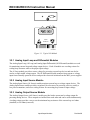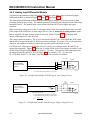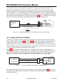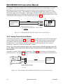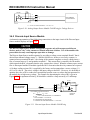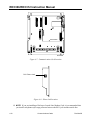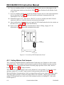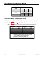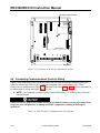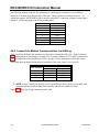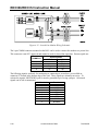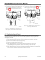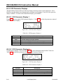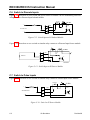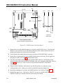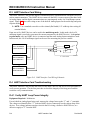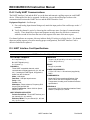
1
Form A4630 Part Number D301059X012 March 2005 ROC306/ROC312 REMOTE OPERATIONS CONTROLLER Instruction Manual Flow Computer Division Website: www.EmersonProcess.com/flow ROC306/ROC312 Instruction Manual Revision Tracking Sheet March 2005 This manual is revised periodically to incorporate new or updated information. The date revision level of each page is indicated at the bottom of the page opposite the page number. A major change in the content of the manual also changes the date of the manual, which appears on the front cover. Listed below is the date revision level of each page. Page All Pages All Pages All Pages Revision Mar/05 Jan/05 Sept/01 FloBoss and ROCLINK are marks of one of the Emerson Process Management companies. The Emerson logo is a trademark and service mark of Emerson Electric Co. All other marks are the property of their respective owners. © Fisher Controls International, Inc. 2002-2005. All rights reserved. Printed in the U.S.A. While this information is presented in good faith and believed to be accurate, Fisher Controls does not guarantee satisfactory results from reliance upon such information. Nothing contained herein is to be construed as a warranty or guarantee, express or implied, regarding the performance, merchantability, fitness or any other matter with respect to the products, nor as a recommendation to use any product or process in conflict with any patent. Fisher Controls reserves the right, without notice, to alter or improve the designs or specifications of the products described herein. ii Rev Mar/05 ROC306/ROC312 Instruction Manual TABLE OF CONTENTS Section 1 – General Information ................................................................................ 1-1 1.1 Scope of Manual...........................................................................................................................1-1 1.2 Manual Contents ..........................................................................................................................1-1 1.3 Product Overview.........................................................................................................................1-2 1.4 Installation Guidelines..................................................................................................................1-3 1.5 Power Supply Requirements ........................................................................................................1-6 1.6 Startup and Operation.................................................................................................................1-10 Section 2 – Master Controller Unit and Related Components ................................ 2-1 2.1 Scope ............................................................................................................................................2-1 2.2 Product Descriptions ....................................................................................................................2-1 2.3 Installation....................................................................................................................................2-7 2.4 Connecting the Power, Ground, and Built-in I/O Wiring ............................................................2-8 2.5 Troubleshooting and Repair .......................................................................................................2-13 2.6 ROC306 and ROC312 Specifications ........................................................................................2-24 Section 3 – Input/Output Modules ............................................................................. 3-1 3.1 Scope ............................................................................................................................................3-1 3.2 Product Descriptions ....................................................................................................................3-1 3.3 Initial Installation and Setup ........................................................................................................3-5 3.4 Connecting the I/O Modules to Wiring........................................................................................3-5 3.5 Troubleshooting and Repair .......................................................................................................3-21 3.6 Removal, Addition, and Replacement Procedures.....................................................................3-29 3.7 I/O Module Specifications .........................................................................................................3-31 Section 4 – Communications Cards............................................................................ 4-1 4.1 Scope ............................................................................................................................................4-1 4.2 Product Descriptions ....................................................................................................................4-1 4.3 Installing Communications Cards ................................................................................................4-8 4.4 Connecting Communications Cards to Wiring ..........................................................................4-13 4.5 Troubleshooting and Repair .......................................................................................................4-20 4.6 Communication Card Specifications..........................................................................................4-22 Appendix A – Lightning Protection Module ............................................................ A-1 iii TABLE OF CONTENTS Rev Mar/05 ROC306/ROC312 Instruction Manual A.1 Product Description.....................................................................................................................A-1 A.2 Connecting the LPM to Wiring ...................................................................................................A-2 A.3 Troubleshooting and Repair ........................................................................................................A-5 A.4 Lightning Protection Module Specifications...............................................................................A-6 Appendix B – Local Display Panel ............................................................................ B-1 B.1 Product Description..................................................................................................................... B-1 B.2 Installation................................................................................................................................... B-2 B.3 Operation..................................................................................................................................... B-4 B.4 Troubleshooting and Repair ...................................................................................................... B-22 B.5 Local Display Panel Specifications........................................................................................... B-23 Appendix C – I/O Simulation..................................................................................... C-1 C.1 Analog Outputs to Analog Inputs................................................................................................ C-1 C.2 Analog Outputs to Ammeter or Voltmeter.................................................................................. C-2 C.3 Discrete Outputs to Discrete Inputs ............................................................................................ C-3 C.4 Discrete Outputs to Pulse Inputs ................................................................................................. C-3 C.5 Potentiometer to Analog Inputs................................................................................................... C-4 C.6 Switch to Discrete Inputs ............................................................................................................ C-5 C.7 Switch to Pulse Inputs ................................................................................................................. C-5 Appendix D – HART Interface Card ........................................................................ D-1 D.1 Product Description.....................................................................................................................D-1 D.2 Installing a HART Interface Card ...............................................................................................D-2 D.3 HART Interface Card Wiring......................................................................................................D-4 D.4 HART Interface Card Troubleshooting.......................................................................................D-4 D.5 HART Interface Card Specifications ..........................................................................................D-5 Glossary........................................................................................................................G-1 Index .............................................................................................................................. I-1 iv TABLE OF CONTENTS Rev Mar/05 ROC306/ROC312 Instruction Manual SECTION 1 – GENERAL INFORMATION 1.1 Scope of Manual This manual focuses on the hardware aspects of the ROC306 and ROC312 Remote Operations Controllers (ROCs) manufactured by Flow Computer Division of Emerson Process Management. This manual includes all versions of these ROCs including the standard and Canadian custody transfer versions. For software aspects, such as configuration, refer to the respective configuration user manual. NOTE: Certain hardware versions and functionality may require higher revisions of ROCLINK configuration software. Verify the version of ROCLINK configuration software. This section contains the following information: Section 1.1 Scope of Manual 1.2 Manual Contents 1.3 Product Overview 1.4 Installation Guidelines 1.5 Power Supply Requirements 1.6 Startup and Operation Page 1-1 1-1 1-2 1-3 1-6 1-10 1.2 Manual Contents This manual contains the following sections: Section 2 details the Master Controller Unit (MCU), built-in input/output (I/O) channels, I/O module board for the ROC312, FlashPAC memory modules, and specifications. Section 3 provides information and specifications for the I/O modules. Section 4 provides details and specifications for the communications cards. Appendix A describes the optional Lightning Protection Module (LPM) and specifications. Appendix B describes specifications and how to use the optional Local Display Panel (LDP) to access operational data in the ROC. With a FlashPAC, the LDP can be used for certain configuration changes. Appendix C shows various ways to set up I/O simulation for troubleshooting components and configurations. Appendix D details the HART® Interface card information and specifications. For more information on software or accessories, please refer to the following manuals. ♦ ROCLINK for Windows Configuration Software User Manual (Form A6091). ♦ ROCLINK 800 Configuration Software User Manual (Form A6121). ♦ ROC/FloBoss Accessories Instruction Manual (Form A4637). 1-1 General Information Rev Mar/05 ROC306/ROC312 Instruction Manual 1.2.1 FCC Information This equipment complies with Part 68 of the Federal Communications Commission (FCC) rules. On the modem assembly is a label that contains, among other information, the FCC certification number and Ringer Equivalence Number (REN) for this equipment. If requested, this information must be provided to the telephone company. A FCC compliant telephone modular plug is provided with this equipment. This equipment is designed to be connected to the telephone network or premises’ wiring, using a compatible modular jack that is Part 68 compliant. See Installation Instructions for details. The REN is used to determine the quantity of devices that may be connected to the telephone line. Excessive RENs on the telephone line may result in the devices not ringing in response to an incoming call. Typically, the sum of the RENs should not exceed five (5.0). To be certain of the number of devices that may be connected to a line (as determined by the total RENs), contact the local telephone company. If this equipment, dial-up modem, causes harm to the telephone network, the telephone company will notify you in advance that temporary discontinuance of service may be required. But if advance notice is not practical, the telephone company will notify the customer as soon as possible. Also, you will be advised of your right to file a complaint with the FCC if you believe it necessary. The telephone company may make changes to its facilities, equipment, operations or procedures that could affect the operation of the equipment. If this happens the telephone company will provide advance notice so you can make the necessary modifications to maintain uninterrupted service. If trouble is experienced with this equipment, dial-up modem, for repair or warranty information, please contact Emerson Process Management, Flow Computer Division (641) 754-2578. If the equipment is causing harm to the telephone network, the telephone company may request that you disconnect the equipment until the problem is resolved. 1.3 Product Overview The ROC306 and ROC312 are microprocessor-based controllers for a variety of field automation applications. The ROCs are used primarily where there is a need for remote flow monitoring, measurement, data archival, and control. You can configure the ROC306 and ROC312 for specific applications including those requiring calculations, PID (Proportional, Integral, and Derivative) Loop Control, or Function Sequence Tables (FSTs) logic/sequencing control. Use ROCLINK configuration software to configure parameters. The modular design of the ROCs makes them cost-effective for small applications. You can select from a variety of communications and operator interface options to customize the installation for a given system. All ROCs are approved for use in Class I – Division 2 locations; in addition, versions are available that also meet requirements for Canadian custody transfer (approved by Industry Canada – Measurement Canada). The ROC306 has three field Analog Inputs, two Discrete or Pulse Inputs, and two Discrete Outputs (one of which can be used for switching auxiliary power). Since these I/O channels are permanently wired into the circuit board, they are called built-in I/O. 1-2 General Information Rev Mar/05 ROC306/ROC312 Instruction Manual The ROC312 has the same built-in I/O channels as the ROC306, plus six “slots” for plug-in I/O modules (modular I/O). The plug-in I/O modules allow any combination of Discrete Inputs, Discrete Outputs, Analog Inputs, Analog Outputs, or Pulse Inputs that an application requires. NOTE: I/O modules must not be used as flow inputs for Canadian custody transfer ROC312 units. FLASHPAC FLASHPAC Figure 1-1 displays the major components that make up the ROC. Refer to Section 2, Master Controller Unit and Related Components, for further hardware and firmware details. C 12 B A C 11 B A C 10 B A 2 1 2 C 1 9 B A C 8 B A C STATUS ROC312 REMOTE OPERATIONS CONTROLLER REMOTE OPERATIONS CONTROLLER INTERFACE RESET COMM DSPL STATUS AUX B A INTERFACE RESET COMM DSPL AUX AI +BAT AI AI DI/PI DO DI/PI AI +BAT -BAT -BAT GND GND NO COM 7 ROC306 AI AI DI/PI DO DI/PI NO T + - T + - T + - S + + - S - S + + - S - N O C O M COM T + - T + - T + - S + + - DOC0087C S - S + + - S - N O C O M DOC0088C Figure 1-1. Typical ROC306 and ROC312 Controllers 1.4 Installation Guidelines Planning is essential to a good installation. This manual provides generalized guidelines for successful installation and operation of the ROC306 and ROC312 products. Be sure to consider location, ground conditions, climate, and accessibility as well as the application of the product in planning an installation. The variety of application firmware (embedded software) in the FlashPAC module allows the ROC306 and ROC312 products to be used in many types of installations. For additional information concerning a specific installation, contact your local sales representative. 1.4.1 Environmental Requirements The ROC306 and ROC312 require protection from direct exposure to rain, snow, ice, blowing dust or debris, and corrosive atmospheres. For installation outside of a building, use a National Electrical Manufacturer’s Association (NEMA) 3 or higher-rated enclosure to protect the ROC. 1-3 General Information Rev Mar/05 ROC306/ROC312 Instruction Manual NOTE: In salt spray environments, it is especially important to ensure that the enclosure is sealed properly, including all entry and exit points. If salt is allowed to enter, it can shorten the life of the lithium battery in the ROC and cause the battery to leak corrosive chemicals. The ROCs are designed to operate over a wide range of temperatures. However, in extreme climates it may be necessary to provide temperature controlling devices to maintain stable operating conditions. In extremely hot climates, a filtered ventilation system or air conditioning may be required. In extremely cold climates, it may be necessary to install a thermostatically controlled heater in the same enclosure as the unit. To maintain a non-condensing atmosphere inside the ROC enclosure in areas of high humidity, it may be necessary to add heat or dehumidification. Section 2, Specifications, contains the environmental specifications for the ROC. 1.4.2 Site Requirements Careful consideration in locating the ROC on the site can help reduce future operational problems. When choosing a location, consider the following items: ♦ Local, state, and federal codes often place restrictions on ROC locations and dictate site requirements. Examples of these restrictions are fall distance from a meter run, distance from pipe flanges, and hazardous area classifications. Ensure that all code requirements are met. ♦ Locate the ROC to minimize the length of signal and power wiring. By code, line power wiring must not cross meter runs. ♦ Solar panels must face due South (not magnetic South) in the Northern Hemisphere and due North (not magnetic North) in the Southern Hemisphere. Make sure nothing blocks the sunlight during any part of the day. ♦ ROCs equipped for radio communications should be located so the antenna has an unobstructed signal path. Antennas should not be aimed into storage tanks, buildings, or other tall structures. If possible, ROCs should be located at the highest point on the site. Overhead clearance should be sufficient to allow the antenna to be raised to a height of at least twenty feet. ♦ To minimize interference with radio communications, locate the ROC away from electrical noise sources, such as engines, large electric motors, and utility line transformers. ♦ Locate ROCs away from heavy traffic areas to reduce the risk of being damaged by vehicles. However, provide adequate vehicle access to aid monitoring and maintenance. 1.4.3 Compliance with Hazardous Area Standards The ROC306 and ROC312 hazardous location approval is for Class I, Division 2, Groups A, B, C, and D. The class, division, and group terms are defined as follows: 1. Class defines the general nature of the hazardous material in the surrounding atmosphere. Class I is for locations where flammable gases or vapors may be present in the air in quantities sufficient to produce explosive or ignitable mixtures. 2. Division defines the probability of hazardous material being present in an ignitable concentration in the surrounding atmosphere. Division 2 locations are locations that are presumed to be hazardous only in an abnormal situation. 1-4 General Information Rev Mar/05 ROC306/ROC312 Instruction Manual 3. Group defines the hazardous material in the surrounding atmosphere. Groups A to D are as follows: ♦ Group A – Atmosphere containing acetylene. ♦ Group B – Atmosphere containing hydrogen, gases, or vapors of equivalent nature. ♦ Group C – Atmosphere containing ethylene, gases, or vapors of equivalent nature. ♦ Group D – Atmosphere containing propane, gases, or vapors of equivalent nature. For the ROC to be approved for hazardous locations, it must be installed in accordance with the National Electrical Code (NEC) guidelines or other applicable codes. When installing units in a hazardous area, installation and maintenance must be performed only when the area is known to be non-hazardous. NOTE: Measurement/Industry Canada approved units normally require a sealed installation. Refer to your local codes for specifics. 1.4.4 Power Installation Requirements Typical sources of primary power for ROC installations are line power and solar power. Be sure to route line power away from hazardous areas, as well as sensitive monitoring and radio equipment. Local and company codes generally provide guidelines for line power installations. Power must adhere rigorously to all local and National Electrical Code (NEC) requirements for line power installations. Solar power allows installation of the ROC in locations where line power is not available. The solar panels and batteries must be properly sized for the application and geographic location to ensure continuous, reliable operation. Information contained in the ROC/FloBoss Accessories Instruction Manual (Form 4637) can help you determine the solar panel and battery requirements to fit your application and location. As a site may have additional power requirements for radios, repeaters, and other monitoring devices, the Flow Computer Division of Emerson Process Management offers accessories to minimize the number of separate power sources required for an installation. Although the ROC306 and ROC312 can operate on 8 to 30 volts dc power, it is good practice to install a low-voltage cutoff device to help protect batteries and other devices not powered by the ROC. 1-5 General Information Rev Mar/05 ROC306/ROC312 Instruction Manual 1.4.5 Grounding Installation Requirements The National Electrical Code (NEC) governs the ground wiring requirements for line-powered equipment. When the equipment uses line power, the grounding system must terminate at the service disconnect. All equipment grounding conductors must provide an uninterrupted electrical path to the service disconnect. This includes wire or conduit carrying the power supply conductors. The National Electrical Code Article 250-83 (1993), paragraph c, defines the material and installation requirements for grounding electrodes. The National Electrical Code Article 250-91 (1993), paragraph a, defines the material requirements for grounding electrode conductors. The National Electrical Code Article 250-92 (1993), paragraph a, provides installation requirements for grounding electrode conductors. The National Electrical Code Article 250-95 (1993) defines the size requirements for equipment grounding conductors. Proper grounding of the ROC helps reduce the effects of electrical noise on unit operation and protect against lightning. Lightning Protection Modules are available to provide additional lightning protection for field wiring inputs and outputs. Refer to Appendix A for additional information about lightning protection. A surge protector installed at the service disconnect on line-powered systems also offers lightning and power surge protection for the installed equipment. Always install telephone surge protectors for ROCs using modem communications cards. All earth grounds must have an earth-to-ground rod or grid impedance of 25 ohms or less as measured with a ground system tester. The grounding conductor should have a resistance of 1 ohm or less between the ROC enclosure ground lug and the earth ground rod or grid. 1.4.6 I/O Wiring Requirements I/O wiring requirements are site and application dependent. Local, state, or NEC requirements determine the I/O wiring installation methods. Direct burial cable, conduit and cable, or overhead cables are options for I/O wiring installations. Sections 2 and 3 contain detailed information on connecting I/O wiring to the ROCs. 1.5 Power Supply Requirements The power consumption of a ROC and related devices determines the requirements for either line or solar power supplies. Table 1-1 and Table 1-2 provide information to assist in determining power supply requirements. Table 1-1 lists the power consumption of the ROC364 and the optional devices available for it. Include in the power consumption calculations of all device relays, meters, solenoids, radios, and other devices that receive DC power from the ROC (excluding those connected to the I/O modules). Table 1-2 lists the power consumption of the various I/O modules available. 1-6 General Information Rev Mar/05 ROC306/ROC312 Instruction Manual A ROC systems power consumption determines power supply and battery size for both line and solar power supplies. Use the information in Table 1-1 and Table 1-2 to determine power requirements. For non-analog I/O, size the I/O module scaling resistors for optimal current to minimize current drain on the power supply. Refer to Section 3. 1.5.1 Determining I/O Channel Power Consumption To determine the I/O Channel Power: 1. Calculate the Duty Cycle of each I/O channel and enter the values in Table 1-1. In estimating total I/O power requirements, the Duty Cycle of each I/O channel (built-in I/O or modular I/O) must be estimated. For a non-analog I/O channel, the Duty Cycle is the percentage of time that the I/O channel is active (maximum power consumption). For example, if a Discrete Output is active for 15 seconds out of every 60 seconds, the Duty Cycle is: Duty Cycle = Active time ÷ (Active time + Inactive time) = 15 sec ÷ 60 sec = 0.25 NOTE: For non-analog I/O, size the I/O module scaling resistors for optimal current to minimize current drain on the power supply. For an analog I/O channel, the Duty Cycle is approximated by estimating the percentage of time the channel spends in the upper half of its range (span) of operation. For example, if an Analog Input wired as a current loop (4 to 20 milliamps) device operates in the upper half of its range 75% of the time, then 0.75 would be used as the Duty Cycle. If the analog channel generally operates around the midpoint of its span, use 0.5 as the Duty Cycle. 2. To calculate the total power consumed by an I/O channel, first select either the 12 Volt or 24 Volt column in Table 1-1 or Table 1-2 and read the minimum (Pmin) and maximum (Pmax) power consumption value from the table for the desired I/O channel. 3. Calculate the power consumption for a channel with the Duty Cycle using the following equation taken into account: Power = (Pmax x Duty Cycle) + [Pmin (1 – Duty Cycle)] 4. Multiply this value by the quantity (QTY) of I/O channels with the same Duty Cycle and enter the calculated value in the Sub-Total column. 5. Repeat the procedure for all other I/O channels used. 6. Total the values in the I/O Modules Sub-Total column in Table 1-2. 7. Enter the I/O Modules Total value in Table 1-1. 8. Calculate the Radio Power Consumption total. Refer to Section 1.5.2, Determining Radio Power Consumption, on page 1-9. 9. Enter the Radio Power Consumption Total value in Table 1-1. 10. Calculate Total power consumption in Table 1-1. 11. Add the power consumption (in mW) of any other devices used with the ROC in the same power system, but not accounted for in the tables to the Total power consumption value in Table 1-1. Refer to Section 1.5.3, Totaling Power Requirements, on page 1-10. 1-7 General Information Rev Mar/05 ROC306/ROC312 Instruction Manual Table 1-1. Power Consumption of the ROC364 and Powered Devices Device MCU (includes minimum Built-in I/O power consumption) Built-in AI Loop (ROC-powered) Built-in DI/PI (ROC-powered) Built-in DO Relay Built-in Auxiliary DO Relay Local Display Panel Serial Comm Card Dial-up Modem Comm Card Leased-Line Modem Comm Card Radio Modem Card HART Interface Card I/O Modules Total from Table 1-2 (ROC312 only) Radio (from Section 1.5.2) Power Consumption (mW) 12 Volts System 24 Volts System Pmax Pmin Pmax Pmin 1050 130 0 0 0 1640 440 65 195 195 130 0 0 0 25 135 395 110 110 80 QTY Duty Cycle 1 N/A SubTotal (mW) 440 275 195 195 25 135 395 110 110 80 N/A N/A N/A N/A N/A N/A N/A N/A N/A N/A N/A N/A Total Notes: 1. For the AI Loop channel, the Duty Cycle is the percent of time spent in the upper half of the operating range. 2. If the ROC has a HART card, be sure to include the power consumption of a Communications Card as well. 1-8 General Information Rev Mar/05 ROC306/ROC312 Instruction Manual Table 1-2. Power Consumption of the I/O Modules I/O Module AI Loop AI Differential AI Source AO Source RTD Input [Pmin is at –50°C (–58F°); Pmax is at 100°C (212F°)] DI Isolated DI Source PI Isolated PI Source Low Level PI SPI Isolated SPI Source DO Isolated DO Source (Pmax is at 57 mA) DO Relay 12 volts DO Relay 24 volts HART Interface Module Power Consumption (mW) 12 Volts System 24 Volts System 2 2 Pmax Pmin Pmax Pmin 170 75 110 145 495 75 305 585 170 75 130 145 495 75 470 585 240 475 475 930 1 1 1 1 1 1 1 1 30 15 N/A 85 10 55 30 70 45 10 55 25 815 375 N/A 685 1 1 1 1 1 1 1 1 30 N/A 20 85 10 205 30 230 45 10 205 25 1585 N/A 470 1285 QTY SubTotal (mW) Duty Cycle1 I/O MODULES TOTAL Notes: 1. For analog I/O channels, the Duty Cycle is the percent of time spent in the upper half of the operating range. 2. The Pmax amount includes any power drawn a by ROC-powered field device, such as a transmitter. 1.5.2 Determining Radio Power Consumption In determining power requirements for radios: 1. Estimate the Duty Cycle for the radio. The Duty Cycle is the percentage of time the radio is transmitting (TX). For example, if a radio is transmitting 1 second out of every 60 seconds, and for the remaining 59 seconds the radio is drawing receive (RX) power, the Duty Cycle is: Duty Cycle = TX time ÷ (TX time + RX time) = 1 sec ÷ 60 sec = 0.0167 2. Calculate the total power consumed by a radio, obtain the power (P) consumption values for transmit and receive from the radio manufacturer’s literature, then use the following equation to calculate the power consumption for a particular Duty Cycle: Power = (PTX x Duty Cycle) + [PRX (1 – Duty Cycle)] 3. Determine the power consumption for all radios that use power from the ROC, and enter the total calculated value in the Sub-Total column in Table 1-1. 1-9 General Information Rev Mar/05 ROC306/ROC312 Instruction Manual 1.5.3 Totaling Power Requirements To adequately meet the needs of the ROC system, it is important to determine the total power consumption to size the solar panel and battery backup requirements accordingly. For total power consumption, add the device values in Table 1-1. Although Table 1-1 and Table 1-2 take into account the power supplied by the ROC to its connected devices, be sure to add the power consumption (in mW) of any other devices used with the ROC in the same power system, but not accounted for in the tables. Convert the total value (in mW) to Watts by dividing it by 1000. mW ÷ 1000 = Watts For selecting an adequate power supply, use a safety factor (SF) of 1.25 to account for losses and other variables not factored into the power consumption calculations. To incorporate the safety factor, multiply the total power consumption (P) by 1.25. PSF = P x 1.25 = _____ Watts To convert PSF to current consumption in amps (ISF), divide PSF by the system voltage (V), either 12 volts or 24 volts. ISF = PSF / V = _____ Amps 1.6 Startup and Operation Before starting the ROC, perform the following checks to ensure that the unit is properly installed. ♦ Make sure the enclosure has a good earth ground. ♦ Make sure the MCU is grounded at the power input connector. ♦ Seat and secure the FlashPAC in the connector. ♦ Seat and secure all I/O modules in their sockets (ROC312 only). ♦ Check the field wiring for proper installation. ♦ Make sure the input power is fused at the power source. ♦ Make sure the input power has the correct polarity. Check the input power polarity before turning the power on. Incorrect polarity can damage the ROC. 1.6.1 Startup Apply power to the ROC. After internal checks are completed, the STATUS LED lights and should stay lit, to indicate that a valid reset sequence has been completed. It takes a few seconds for the STATUS LED to light. If any of the indicators do not light, refer to Section 2 for possible causes. Keep in mind that the ROC306 or ROC312 will start up on power that is as low as 8 volts; however, devices powered by the ROC may not operate at this level. 1-10 General Information Rev Mar/05 ROC306/ROC312 Instruction Manual 1.6.2 Operation Once startup is successful, configure the ROC to meet the requirements of the application. The appropriate ROCLINK configuration software user manual describes in detail the procedure for configuring the ROC. Once the ROC is configured and I/O is calibrated, it can be placed into operation. ROC configuration must be performed only in an area known to be non-hazardous. The ROC can be operated from a host system using ROCLINK configuration software or other compatible software. Consult with your local sales representative for more information on host system compatibility. 1.6.2.1 Local Display Panel The Local Display Panel (LDP) is an ASCII terminal with a 4-line by 20-character Liquid Crystal Display (LCD) and a 4-key keypad. Refer to Appendix B. 1-11 General Information Rev Mar/05 ROC306/ROC312 Instruction Manual SECTION 2 – MASTER CONTROLLER UNIT AND RELATED COMPONENTS 2.1 Scope This section describes the core components of the ROC306 and the ROC312, including the Master Controller Unit (MCU), the FlashPAC module, and the front panel. In most cases, the two types of ROCs and the versions of each are identical in design and operation. The descriptions and procedures in this section apply to all ROC types and versions. In areas where the types or versions differ, the differences are noted. This section contains the following information: Section 2.1 Scope 2.2 Product Descriptions 2.3 Installation 2.4 Connecting the Power, Ground, and Built-in I/O Wiring 2.5 Troubleshooting and Repair 2.6 ROC306 and ROC312 Specifications Page 2-1 2-1 2-7 2-8 2-13 2-24 2.2 Product Descriptions The following paragraphs describe individual components of the ROC306 and the ROC312. 2.2.1 Master Controller Unit The Master Controller Unit (MCU) is the “brain” of the ROC. The MCU consists of: ♦ NEC V25+ microprocessor. ♦ Diagnostic inputs. ♦ On-board memory. ♦ Status indicators. ♦ FlashPAC module sockets. ♦ Six connectors for modular I/O (ROC312 only). ♦ Operator interface port. ♦ Reset switch (except Canadian Custody Transfer version). ♦ Local display port. ♦ Built-in field Input/Output (I/O) channels. ♦ Communications port. 2-1 Master Controller Unit and Related Components Rev Mar/05 ROC306/ROC312 Instruction Manual COM PORTS DOC0097A ROC312 Upper Cover, Rear View DOC0096A MCU Front View Figure 2-1. Front and Back Views of MCU with Covers Removed The ROC derives processing power from a National Electrical Code (NEC) V25+ microprocessor. The NEC V25+ is a 16-bit Complementary Metal Oxide Semiconductor (CMOS) microprocessor featuring dual 16-bit internal data buses and a single 8-bit external data bus. The ROC can address up to one megabyte of memory and features high-speed direct memory access. The on-board memory on the Main Circuit Board (MCU) includes 128 kilobytes of battery-backed, Random Access Memory (RAM) for storing data, and 8 kilobytes of Electrically Erasable Programmable Read-Only Memory (EEPROM) for storing configuration parameters. Plug-in sockets are provided for the required FlashPAC module. Refer to Section 2.2.2, FlashPAC Module, on page 2-3. One over-current device and a soldered fuse on the MCU circuit board provide input power protection. The over-current device protects the fuse. Another over-current device on the MCU circuit board protects the analog “+T” 24 volts dc outputs. The operator interface connector (labeled Interface) provides direct communication between the ROC and the serial port of an operator interface, such as a notebook computer (COM1). The interface gives you access to the functionality of the ROC. The display connector (DSPL) links the MCU to an optional Local Display Panel (LDP). The LDP provides local monitoring of I/O and database parameters, as set up by using ROCLINK configuration software. For a ROC with a FlashPAC, limited editing of parameter values can be performed with the LDP. Refer to Appendix B, Local Display Panel. 2-2 Master Controller Unit and Related Components Rev Mar/05 ROC306/ROC312 Instruction Manual The communications connector (COMM) accesses an optional communications card installed on the MCU board. The communications card provides serial data communications, modem, radio modem, or leased-line modem communications. One terminal block on the front panel provides termination for the input power, ground, and an auxiliary Discrete Output. The auxiliary Discrete Output provides a normally-open relay contact. This output can be used to switch power to auxiliary devices, such as a radio. Six field I/O terminal blocks on the front panel provide termination for the built-in field I/O channels including three Analog Inputs, two Discrete or Pulse Inputs, and one Discrete Output. On the ROC312, an I/O module board allows you to plug in a variety of I/O modules through the case cover. The I/O module board is fastened to the case cover. Two diagnostic Analog Inputs on the MCU circuit board monitor the voltage of the input power and the board temperature. LED indicators indicate the ROC operational Status, auxiliary output relay state (labeled AUX), DI/PI input/output state, and DO relay state. Refer to Table 2-2, LED Indicator Descriptions, on page 2-14. The state indicators, when on, show the input or output is active. Using a FlashPAC, version 2.00 and greater, the RESET switch permits a reset. If a LDP is installed, the left-most button on the LDP permits a reset by depressing the button or switch down during power-up. Refer to Section 2.5, Troubleshooting and Repair, on page 2-13. NOTE: On units approved for Industry Canada custody transfer use, the RESET switch has been disabled. The MCU is housed in a metal case that protects the electronics from physical damage. For protection from outdoor environments, the ROC must be housed in a separate enclosure. Industry Canada (also called Measurement Canada) approved ROCs have the metal case cover installed with internal hexhead screws. The heads of these screws have a hole drilled through them that allow the units to be sealed with a wire. 2.2.2 FlashPAC Module The FlashPAC module contains the operating system, the applications firmware, and communications protocol, as well as memory storage for history logs and user programs. The FlashPAC module is available both in the standard version and in a version approved by Measurement/Industry Canada, which is supplied in a Canadian Custody Transfer ROC. The applications firmware consists of functions contained in flash Read-Only Memory (ROM), such as: ♦ American Gas Association Flow Calculations – AGA3 (1985 and 1992 algorithms) and AGA7, with metric conversion. ♦ PID (Proportional, Integral, and Derivative) Loop Control. ♦ Support for Function Sequence Tables (FSTs). ♦ Communications Enhancement includes dial-up Spontaneous-Report-by-Exception (SRBX) alarming. ♦ Local Display Panel Enhancement (database point monitoring with configuration access). ♦ Radio Power Control (FlashPAC Version 2.1 or greater). 2-3 Master Controller Unit and Related Components Rev Mar/05 ROC306/ROC312 Instruction Manual The firmware is programmed into flash memory at the factory, but can be reprogrammed in the field, should the need arise. Use ROCLINK configuration software to configure application programs. NOTE: Certain hardware versions and functionality may require higher revisions of ROCLINK configuration software. Verify the version of ROCLINK configuration software. A FlashPAC module contains 512 kilobytes (352 kilobytes used) of flash Read-Only Memory (ROM) and 512 kilobytes of battery-backed static Random-Access Memory (RAM). A FlashPAC module is required for the ROC to operate. A self-contained lithium battery provides back-up power for the RAM. Figure 2-2 shows a FlashPAC module. When used with ROCLINK configuration software, a ROC with a FlashPAC module can save a configuration to disk as a *.FCF file and later restore configuration files back into a ROC with a FlashPAC. ROCLINK configuration software includes diagnostic functions for viewing memory allocation and for loading user programs into flash memory. The RAM in a FlashPAC can store 87 history points, each holding 35 days of hourly values. Besides storing history data, the RAM in a FlashPAC stores user program data downloaded through a communications port. The FlashPAC’s flash ROM is programmed with firmware at the factory. Table 2-1 on page 2-5 shows how the ROC memory is allocated. Each memory location range (for example, 00000 to 1FFFF) represents 128 kilobytes of memory. FLASHPAC W20217X0012 ROC300 SERIES ------------VER: 2.10 PATENT 5339425 ® DOC0292A Figure 2-2. FlashPAC Module 2-4 Master Controller Unit and Related Components Rev Mar/05 ROC306/ROC312 Instruction Manual Determining FlashPAC Version To determine the version of FlashPAC module, use ROCLINK configuration software. Select ROC > Information > Other Information > Version Name, which contains the part and version numbers. ♦ Part Number W20217 is the standard FlashPAC. ♦ Part Number W20264 is the Measurement/Industry Canada FlashPAC. NOTE: The version may have been updated by a download of upgrade firmware into the module, so the label on the actual FlashPAC module might not be accurate. Table 2-1. ROC Memory Map Memory Location 00000 to 1FFFF 20000 to 3FFFF 40000 to 5FFFF 60000 to 7FFFF 80000 to 81FFF 88000 to 9FFFF A0000 to BFFFF C0000 to DFFFF E0000 to FFFFF ROC306/312 with FlashPAC Base RAM RAM in FlashPAC RAM in FlashPAC RAM in FlashPAC EEPROM (on-board) Flash ROM RAM in FlashPAC Flash ROM Flash ROM Usage Alarm/Event Logs, and such. History Data Area; part is for scratch-pad memory in FlashPAC History Data Area History Data in FlashPAC User Configuration Data Operating System and Applications User Program Data in FlashPAC User Program Code in FlashPAC Operating System Firmware 2.2.3 Built-in I/O Channels The ROC306 and ROC312 units each have several built-in field I/O channels: ♦ Three Analog Inputs (AI). The Analog Inputs can also provide connections for HART protocol devices when a HART Interface Card is installed. ♦ Two Discrete Input or Pulse Inputs (DI/PI) provide interfacing with measurement and control instrumentation. ♦ Two Discrete Outputs (DO) provide a normally-open relay contact (one is designated as the auxiliary output). Figure 2-3 shows the location of the terminal blocks for the built-in field I/O. One of the Discrete Outputs is called the auxiliary output (designated Point Number E6 by ROCLINK configuration software). It can be used for switching power to a device, such as a radio or as a control output. The auxiliary output uses the NO and COM terminals located in the lower left-hand corner of the ROC front panel. Refer to Figure 2-3. 2-5 Master Controller Unit and Related Components Rev Mar/05 ROC306/ROC312 Instruction Manual ROC306 REMOTE OPERATIONS CONTROLLER STATUS INTERFACE RESET COMM DSPL AUX Power Terminal Block AI +BAT AI DI/PI DI/PI AI DO -BAT GND Auxiliary Discrete Output NO T COM + - T + - T + - S + + - S - S + + - S - N O C O M DOC0092T Figure 2-3. I/O Terminal Block Location The Discrete or Pulse Inputs (DI/PI) are selected and configured using ROCLINK configuration software. The three selections for the DI/PI (A4/A5 Functions) are located in ROC > Flags > Advanced Features. 2.2.4 Diagnostic Inputs The ROC306 and ROC312 monitor the input voltage (Analog Input Point Number E2) and the board temperature (Analog Input Point Number E5) with two diagnostic Analog Inputs. 2.2.5 ROC312 I/O Module Board The ROC312 has an I/O module board, which provides sockets for up to six I/O modules. The plugin I/O modules allow any combination of Discrete Inputs, Discrete Outputs, Analog Inputs, Analog Outputs, or Pulse Inputs that an application requires. Section 3, Input/Output Modules, describes the I/O modules. On units with Industry Canada approval, modular I/O must not be used for flow measurement inputs. 2-6 Master Controller Unit and Related Components Rev Mar/05 ROC306/ROC312 Instruction Manual 2.3 Installation 8.00 6.50 .31 (REMOVAL CLEARANCE) .75 8.50 8.88 .25 The ROC306 or ROC312 typically mounts in a ROC enclosure, which has a backplate with tapped mounting holes to accommodate the unit as shown in Figure 2-4. DOC0095A #8 PAN HEAD SCREW (4) Figure 2-4. Mounting Dimensions 2.3.1 Mounting Use the following procedure to mount the unit on a panel or in an enclosure. Equipment and Tools Required: Drill and drill bit (1/4 inch) Tap and die Philips screwdriver 1. Locate four holes for number 8-32 screws, 165 millimeter (6.5 inches) between centers horizontally and 216 millimeter (8.5 inches) vertically. If holes are not present, drill and tap them. 2. Partially insert the top two screws and place the keyhole slots of the ROC over them. 3. Insert the lower two screws and tighten all four screws. 4. To add I/O modules (ROC312 only), refer to Section 3, Input/Output Modules. To add a communications card, refer to Section 4. If you need to install accessories for use with the ROC, refer to the ROC/FloBoss Accessories Instruction Manual (Form A4637). 2-7 Master Controller Unit and Related Components Rev Mar/05 ROC306/ROC312 Instruction Manual 2.4 Connecting the Power, Ground, and Built-in I/O Wiring The following sections describe how to connect the ROC to power, ground, field devices for the builtin I/O channels, and communications devices. Note that the power and I/O wiring terminal blocks accept up to 12-gauge American Wire Gauge (AWG) solid or stranded copper wire. For connections to field devices through I/O modules (ROC312 only), refer to Section 3, Input/Output Modules. If you are using a Lightning Protection Module (LPM), refer to Appendix A. NOTE: Use a standard screwdriver with a slotted (flat bladed) 1/8" width tip when wiring all terminal blocks. 2.4.1 Connecting Ground Wiring Equipment Required: Small flat-blade screwdriver The ROC and related components must be connected to earth ground. Each component connects to earth ground (typically an enclosure ground bar) using the grounding screw provided. The components should be linked using an 18 AWG or larger conductor. The wire that connects between the ROC enclosure ground bar and ground should be at least 12 AWG. Ground wiring requirements are governed by the National Electrical Code (NEC) code or other applicable codes. Excerpts from the NEC code are contained in Section 1, General Information. Connect the GND terminal on the ROC’s power connector to the enclosure ground with 12 AWG wire. Connect the enclosure ground to an appropriate ground rod or grid. 2.4.2 Connecting Main Power Wiring Equipment Required: Small flat-blade screwdriver Connect power to the ROC through the plug-in terminal block on the front panel. Refer to Figure 2-5. Always use good wiring practice when sizing, routing, and connecting power wiring. All wiring must conform to state, local, and national codes. The power wiring terminal block can accommodate a wide range of wire gauges. Use 18 AWG wire or larger for all power wiring. Connect the dc power source to the +BAT and –BAT terminals. Make sure the hook-up polarity is correct. Refer to Figure 2-5. 2-8 Master Controller Unit and Related Components Rev Mar/05 ROC306/ROC312 Instruction Manual ROC306 REMOTE OPERATIONS CONTROLLER STATUS INTERFACE RESET COMM DSPL AUX Power Connector AI +BAT AI DI/PI AI DI/PI DO -BAT GND NO COM T + - T + - T + - S + + - S - S + + - S - N O C O M DOC0092Z Figure 2-5. Power Wiring Connections 2-9 Master Controller Unit and Related Components Rev Mar/05 ROC306/ROC312 Instruction Manual 2.4.3 Connecting Wiring to Built-in Analog Inputs Equipment Required: Flat-blade (1/8 inch width) screwdriver The Analog Input channels have three field wiring terminals per channel. The “T” terminal provides +24 volts dc for loop-powered devices. Each channel has a current regulator in series with the “T” terminal to provide short-circuit protection. The maximum output of each terminal is 25 milliamps. The ROC is supplied with a 250-ohms scaling resistor between the “+” and “–” Analog Input terminals. The “+” terminal is the positive signal input, and the “–” terminal is the negative signal input. These terminals accept a signal in the 1- to 5-volts range. Since the “–” terminal connects to common (COM), the Analog Input channels are single-ended inputs only. If a HART® Interface Card is installed, I/O devices that use the HART protocol can be connected to these Analog Input channels. Refer to Appendix D for wiring HART devices. To use a 4- to 20-milliamps current signal, install a 250-ohm resistor (0.1%, 1/8 watts supplied) between the “+” and “–” terminals. Note that this input can be used for ROC-powered devices only. Figure 2-6 shows the wiring for a typical current signal. AI + ROC-POWERED CURRENT LOOP DEVICE T 250 OHM Vs I LIMIT + - Vs = 8 to 30 VDC T = 24 VDC +SIGNAL = 4 to 20 mA DOC4001A-mod. Figure 2-6. Current Signal on Built-in Analog Input Figure 2-7 shows the wiring for a typical voltage signal. An externally powered device supplies the voltage signal. AI EXTERNAL/ SELF-POWERED DEVICE T + I LIMIT Vs + - Vs = 8 to 30 VDC T = 24 VDC +SIGNAL = 1 to 5 VDC DOC4002A-mod. Figure 2-7. Voltage Signal on Built-in Analog Inputs 2-10 Master Controller Unit and Related Components Rev Mar/05 ROC306/ROC312 Instruction Manual 2.4.4 Connecting Wiring to Built-in Discrete/Pulse Inputs Equipment Required: Flat-blade (1/8 inch width) screwdriver The two built-in Discrete/Pulse Input channels are optically isolated from the ROC circuit board and allow a wide variety of input options. You can configure the inputs as either Discrete Inputs or medium-speed Pulse Inputs. When used as a Pulse Input, the I/O channel has a maximum operating frequency of 1000 hertz with a Pulse Input scan of 200 milliseconds and a maximum 50% Duty Cycle. The Discrete/Pulse Input (DI/PI) has four field terminals per channel. Terminal “S+” is a positive source (PS) voltage (V) that follows the voltage of the ROC input power. Terminal “+” is the positive signal input, terminal “–” is the negative signal input, and terminal “S–” is the channel common. The terminals may be wired as either a sourced or an isolated input. To use the channel as an isolated input as shown in Figure 2-8, connect the field wires to terminals “+” and “–”. Make sure to observe the correct polarity on hook-up. The field device sends a voltage through terminal “+”. The voltage activates the LED to show an active circuit (ON), and causes the optical circuit to signal the ROC. DI/PI SELF-POWERED DISCRETE/PULSE DEVICE S+ + - VPS 2.5K + S- DOC4003A Figure 2-8. Isolated Built-in Discrete/Pulse Input For use as a sourced input as shown in Figure 2-9, jumper terminals “S+” and “+” together. Connect the field device positive wire to terminal “–” and the field negative lead to terminal “S–”. When the discrete field device conducts, the source power flows through the LED to show an active circuit (ON) and triggers the optical circuit to signal the ROC through terminal “S–” to ground. DI/PI ROC-POWERED DISCRETE/PULSE DEVICE JUMPER + - S+ VPS 2.5K + S- DOC4004A Figure 2-9. Sourced Built-in Discrete/Pulse Input 2-11 Master Controller Unit and Related Components Rev Mar/05 ROC306/ROC312 Instruction Manual 2.4.5 Connecting Wiring to Built-in Discrete Output Equipment Required: Flat-blade (1/8 inch width) screwdriver The built-in Discrete Output channel is a normally-open, single-pole, single-throw relay. The relay contacts have a 5-amps rating. An LED lights when the relay coil is energized. If you use the relay to switch voltages high enough to be harmful, use a label to warn maintenance personnel of the potential hazard. Figure 2-10 shows a typical Discrete Output wiring diagram. DO SELF-POWERED DISCRETE DEVICE + - NO +5V 1.2K COM CONTROL DOC4005A Figure 2-10. Built-in Discrete Output 2.4.6 Connecting Wiring to Auxiliary Discrete Output Equipment Required: Flat-blade (1/8-inch width) screwdriver The ROC provides a normally-open, single-pole, single-throw relay contact (rated at 5 amps) for switching radio transmitter power or for use as a field output. The LED labeled AUX lights with relay activation. Figure 2-11 shows the wiring in a switching application. Refer to Figure 2-10 for wiring connections as a field output. In either case, configure the output through ROCLINK configuration software (Discrete Output Point Number E6). Use the NO and COM terminals on the power terminal block to connect wiring. If you use the relay to switch voltages high enough to be harmful, be sure to attach a label for warning maintenance personnel of the potential hazard. AUX RADIO TRANSMITTER POWER, ETC. NO +5V 1.2K COM - + CONTROL DOC4006A Figure 2-11. Auxiliary Discrete Output 2-12 Master Controller Unit and Related Components Rev Mar/05 ROC306/ROC312 Instruction Manual 2.4.7 Connecting Communications Wiring Equipment Required: None The ROC has the flexibility to communicate with external devices using several different formats and protocols. Connectors located on the front panel of the ROC provide both operator interface and data communications. The operator interface connector labeled Interface is a serial EIA-232 (RS-232) port for communications to a configuration and monitoring device. This device is typically a personal computer, such as a notebook PC. A null modem cable (wires to pins 2, 3, and 5, with the wires between pins 2 and 3 cross-connected) is normally connected between the Interface connector and the PC. Figure 2-12 shows the wiring for this port. Figure 2-12. Operator Interface Connector Wiring The DSPL connector is a parallel port for dedicated communications to an optional Local Display Panel. The cable supplied with the Local Display Panel plugs into this connector. One data communications port is available. The port is a 9-pin connector labeled COMM and provides access to external devices via an optional plug-in communications card. Section 4 details the communications card types available for the ROCs and connecting wiring. 2.5 Troubleshooting and Repair The troubleshooting and repair procedures help identify and replace faulty boards and FlashPAC modules. Return faulty boards and FlashPAC modules to your local sales representative for repair or replacement. The following tools are required for troubleshooting: ♦ IBM-compatible personal computer. ♦ ROCLINK configuration software. ♦ Digital multimeter, Fluke 8060A or equivalent. 2-13 Master Controller Unit and Related Components Rev Mar/05 ROC306/ROC312 Instruction Manual 2.5.1 LED Indicators The LED indicators, located on the front panel of the ROC, give a first-level indication of the operation of the ROC. Figure 2-13 shows the location of the indicators and Table 2-2 describes them. After the power is switched on, the STATUS indicator lights, and remains lit to indicate normal operation. If the STATUS indicator does not remain on, refer to Table 2-2 for possible causes. ROC306 REMOTE OPERATIONS CONTROLLER STATUS INTERFACE RESET COMM DSPL AUX AI +BAT AI DI/PI DI/PI AI DO -BAT GND NO T COM + - T + - T + - S + + - S - S + + - S - N O C O M DOC0092A Figure 2-13. LED Indicator Locations Table 2-2. LED Indicator Descriptions Indicator LED ON BLINKING STATUS OFF AUX DI/PI DO 2-14 ON OFF ON OFF ON OFF Meaning Successful startup and the processor is running. The processor is not running and is attempting to restart. Possible low battery or bad FlashPAC. No input power. Circuit protection devices overloaded. Insufficient voltage available to power up the ROC. Input power polarity reversed. Relay energized. Relay de-energized. Input active. Input not active. Relay energized. Relay de-energized. Master Controller Unit and Related Components Rev Mar/05 ROC306/ROC312 Instruction Manual 2.5.2 Fuses The ROC306 and ROC312 use the overload protection devices listed in Table 2-3. The overload protection devices are not field replaceable. Table 2-3. Overload Protection Devices ID F1 PTR1 PTR2 Rating 3A 1.1A 0.25A Use 100 VA power limiting fuse. Input power protection. Analog Input 24 volts dc power (“T” terminal). 2.5.3 RAM Backup Procedure with ROCLINK Configuration Software Before removing power to the ROC, perform the following procedure to avoid losing the ROC configuration and other data stored in RAM (in the event that backup power is not working). User programs cannot be saved to disk from the ROC. If user programs are lost or corrupted, reload them from their original disk files as instructed in the appropriate ROCLINK configuration software user manual. 1. Save the current configuration data by selecting ROC > Flags > Write to EEPROM or Flash Memory Save Configuration as instructed in the applicable ROCLINK configuration software user manual. This action saves most of the ROC configuration (but not logs or FST programs) into the permanent memory accessed when a Cold Start is performed. 2. Save the current configuration data to disk using File > Download as instructed in the applicable ROCLINK configuration software user manual. This action saves the ROC configuration (but not FSTs) to a disk file. 3. Save all historical database logs (Minute, Hourly, and Daily), Event Log, and Alarm Log to disk using ROC > Collect Data “All” function as explained in the applicable ROCLINK configuration software user manual. 4. Save the FSTs to disk using Utilities > FST Editor > FST > Write function in the FST Editor. Refer to the FST Editor in the applicable ROCLINK configuration software user manual. 2.5.4 Verifying Battery Voltage Equipment Required: Voltmeter The on-board RAM and the real-time clock receive backup power from Battery B1. Battery B1 is a 3.6-volts lithium battery, with an expected life of 5 to 10 years. If the ROC is powered down for extended periods, this may shorten the life of the battery. In older ROCs, Battery B1 is soldered onto the main circuit board. A blinking Status LED may be an indication of a bad RAM/clock battery. To check the battery voltage: 1. Remove power from the ROC. 2. Remove the FlashPAC module as described in Section 2.5.10 on page 2-18. 2-15 Master Controller Unit and Related Components Rev Mar/05 ROC306/ROC312 Instruction Manual 3. Remove the cover. 4. Use a voltmeter to measure the voltage of the battery between power supply common (–BAT) and either end of Resistor R2, which is located at the top of the MCU board. NOTE: You may need to remove the communications card to access R2. 5. If the voltage reading is less than 3.6 volts, the battery must be replaced. Refer to Section 2.5.11, Replacing the Battery, on page 2-19. If the battery in soldered-in, replacement requires the removal of the MCU board from the housing, the MCU assembly should be returned to your local sales representative for this action. Refer to Section 2.5.12, Installing and Removing the MCU Assembly, on page 2-20. 2.5.5 Verifying the ROC can Communicate with the PC Equipment Required: Personal computer with ROCLINK configuration software installed To verify that the ROC is communicating with the PC running ROCLINK configuration software: 1. Connect the ROC to the PC and launch ROCLINK configuration software. 2. If the ROC is communicating with ROCLINK configuration software, COM1, COM2, COM3, or COM4 displays in the lower right corner of the screen. 2.5.6 Verifying RAM Equipment Required: Personal computer with ROCLINK configuration software installed. To detect bad RAM: 1. Connect the ROC to ROCLINK configuration software. 2. Select ROC > Information > Other Information tab and verify that RAM Installed is labeled PRESENT. The problem could be a bad backup battery or a bad solder joint of the RAM chip. 2.5.7 Performing a Warm Start A Warm Start temporarily suspends all input/output (I/O) scanning. I/O processes are restarted from their last calculated values. A Warm Start clears and restarts all user-enabled flags. A Warm Start also starts all FSTs to the first instruction. NOTE: If your ROC is semi-functional, refer to Section 2.5.3, RAM Backup Procedure with ROCLINK Configuration Software, on page 2-14 before removing power from your ROC. To perform a Warm Start using the configuration software: 1. Connect the ROC to the PC running ROCLINK configuration software. 2. Click ROC > Flags > Warm Start and click Apply. To perform a Warm Start using the power option: 1. Remove power from your ROC. 2. Reapply power to the ROC. 2-16 Master Controller Unit and Related Components Rev Mar/05 ROC306/ROC312 Instruction Manual 2.5.8 Performing a Cold Start A Cold Start allows you to reset your ROC based on the selected option. NOTE: If your ROC is semi-functional, refer to Section 2.5.3, RAM Backup Procedure with ROCLINK Configuration Software, on page 2-14 before removing power from your ROC. To perform a Cold Start: 1. Connect the ROC to ROCLINK configuration software. 2. Select ROC > Flags. 3. Select the Cold Start checkbox. 4. Click the Cold Start Options button. 5. Select the appropriate option and click OK. 2.5.9 Performing a Reset When you have tried the previous methods for convincing your ROC to cooperate and all other troubleshooting procedures have failed, perform a reset before returning your ROC to the factory. A reset returns the ROC’s configuration of I/O points, PID, AGA points, communication parameters, system variables, Opcode tables, and LCD displays to their default values. A reset also sets the FST run flags to zero and clears all Alarm and Event Logs. NOTE: If your ROC is semi-functional, refer to Section 2.5.3, RAM Backup Procedure with ROCLINK Configuration Software, on page 2-14 before removing power from your ROC. 1. Remove power from the ROC. 2. Press the Reset button and hold while returning power to the ROC. 3. Connect your ROC to a computer running ROCLINK configuration software. 4. Select Utilities > Download User Programs or User Program Administrator. 5. Clear all user programs (Clear All) and click OK or Update. 6. Select ROC > Flags. 7. Select the Clear EEPROM checkbox or click Flash Memory Clear and click Apply. 8. Select the Cold Start checkbox. 9. Click the Cold Start Options button. 10. Select the Restore Config & Clear All of the Above (Cold Start & Clear All) radio button and click OK. 2-17 Master Controller Unit and Related Components Rev Mar/05 ROC306/ROC312 Instruction Manual 2.5.10 Replacing a FlashPAC Equipment Required: Personal computer with ROCLINK configuration software installed A faulty FlashPAC module can be suspected if the: ♦ Status LED is blinking. ♦ Data is being corrupted. ♦ ROC is not communicating. ♦ RAM fails to show up in ROCLINK configuration software as being installed. To replace a FlashPAC module: NOTE: For Canadian custody transfer units, maintenance and resealing of the ROC must be performed by authorized personnel only. When repairing units in a hazardous area, change components only in an area known to be nonhazardous. There is a possibility of losing the ROC configuration and historical data held in RAM while performing the following procedure. As a precaution, save the current configuration and historical data to permanent memory as instructed in Section 2.5.3, RAM Backup Procedure with ROCLINK Configuration Software, on page 2-14. During this procedure, all power is removed from the ROC and devices powered by the ROC. Ensure all connected input devices, output devices, and processes remain in a safe state when power is removed from the ROC and when power is restored to the ROC. 1. Back up your RAM to avoid losing data. Refer to Section 2.5.3, RAM Backup Procedure with ROCLINK Configuration Software, on page 2-14. 2. Remove power by unplugging the block on the power terminal block. 3. Remove the FlashPAC retainer by loosening the two thumbscrews and sliding the retainer over the FlashPAC module. 4. Lift up on the FlashPAC to be replaced and remove it from the socket. Before installing a new FlashPAC module, make sure the FlashPAC connector pins are straight. Bent pins can damage the mating connector. Do not attempt to straighten bent pins; instead, replace the FlashPAC. 5. Align the key on the FlashPAC socket with the key of the MCU socket. Carefully insert the FlashPAC module in the socket and press it in firmly, but gently to seat the FlashPAC. The FlashPAC should move inward slightly. Verify that the FlashPAC is seated into the connector by gently lifting up on the FlashPAC. If it comes out easily, repeat the process. 2-18 Master Controller Unit and Related Components Rev Mar/05 ROC306/ROC312 Instruction Manual 6. Ensure that the foam insert (for an unused slot) is properly seated in the module retainer, then carefully slide the retainer over the FlashPAC module and tighten the thumbscrews. Make sure that the sloped surface of the retainer is down. 7. Plug in the five-terminal connector to restore power. If a FlashPAC was replaced, a Cold Start (uses EEPROM, Internal Config Memory, or Flash Memory values) automatically occurs and may take a few seconds. 8. Using ROCLINK configuration software, check the configuration data including ROC Displays and FSTs, and load or modify them as required. In addition, load and start any user programs as needed. 9. Verify that the ROC performs as required. 10. If you changed the configuration, save the current configuration data to memory by selecting ROC > Flags > Write to EEPROM or Flash Memory Save Configuration as instructed in the applicable ROCLINK configuration software user manual. 11. If you changed the configuration including the history database, ROC Displays, or FSTs, save them to disk. 2.5.11 Replacing the Battery This section details how to replace the ROC battery. When repairing units in a hazardous area, change components only in an area known to be nonhazardous. There is a possibility of losing the ROC configuration and historical data held in RAM while performing the following procedure. As a precaution, save the current configuration and historical data to permanent memory as instructed in Section 2.5.3, RAM Backup Procedure with ROCLINK Configuration Software, on page 2-14. During this procedure, all power is removed from the ROC and devices powered by the ROC. Ensure all connected input devices, output devices, and processes remain in a safe state when power is removed from the ROC and when power is restored to the ROC. 1. Back up your RAM to avoid losing data. Refer to Section 2.5.3, RAM Backup Procedure with ROCLINK Configuration Software, on page 2-14. 2. Remove power from the ROC at the power terminal plug in. 3. Remove the four screws from the front cover of the ROC. 4. Remove the screw from the communications card if necessary. 5. Remove the communications card. 6. Locate the unused battery socket (typically B2) on the processor board and insert the new battery. 2-19 Master Controller Unit and Related Components Rev Mar/05 ROC306/ROC312 Instruction Manual 7. Remove the old battery from the other battery socket (typically B1) by sliding the hold-down clip to one side and lifting the battery from the MCU board. If the clip does not readily rotate, you may need to loosen the screw that secures the hold-down clip. 8. Move the hold-down clip to the new battery and tighten if necessary. 9. Replace the communications card. 10. Replace the communications card’s screw. 11. Replace the front cover and four screws. 12. Return power to the ROC at the power terminal plug in. 2.5.12 Installing and Removing the MCU Assembly Equipment Required: Personal computer with ROCLINK configuration software To remove or install the MCU assembly, use the following procedure. NOTE: For Canadian custody transfer units, maintenance and resealing of the ROC must be performed by authorized personnel only. When repairing units in a hazardous area, change components only in an area known to be nonhazardous. There is a possibility of losing the ROC configuration and historical data held in RAM while performing the following procedure. As a precaution, save the current configuration and historical data to permanent memory as instructed in Section 2.5.3, RAM Backup Procedure with ROCLINK Configuration Software, on page 2-14. During this procedure, all power is removed from the ROC and devices powered by the ROC. Ensure all connected input devices, output devices, and processes remain in a safe state when power is removed from the ROC and when power is restored to the ROC. 1. Back up the RAM to avoid losing data. Refer to Section 2.5.3, RAM Backup Procedure with ROCLINK Configuration Software, on page 2-14. 2. Unplug the power connector from the ROC. 3. Unplug all connectors and I/O terminal blocks from the ROC. 4. Loosen the four screws that secure the backplate of the ROC case to the enclosure or other panel. 5. Move the ROC up to slide the keyhole slots in the case backplate into position to fit over the heads of the two alignment screws. Lift the ROC away from the backplate. 6. Remove the FlashPAC and I/O modules, if necessary. 7. Remove HART Interface Card and communications card, if necessary. 2-20 Master Controller Unit and Related Components Rev Mar/05 ROC306/ROC312 Instruction Manual 8. Return the MCU as an assembly to your local sales representative for repair. The MCU board must remain in the metal case when returned. 9. To install a new or repaired MCU assembly, reverse the procedure used for removal in the previous steps. 10. Reconnect power to the ROC by plugging in the power terminal connector. 11. Using ROCLINK configuration software, check the configuration data including ROC Displays and FSTs, and load or modify them as required. In addition, load and start any user programs as needed. 12. Verify that the ROC performs as required. 13. If you changed the configuration, save the current configuration data to memory by selecting ROC > Flags > Write to EEPROM or Flash Memory Save Configuration as instructed in the applicable ROCLINK configuration software user manual. Also, if you changed the configuration including the history database, ROC Displays, or FSTs, save them to disk. 2.5.13 Testing the Built-in Analog Inputs Equipment Required: Multimeter 1 kilohm resistor 0 to 5 kilohms potentiometer Personal computer with ROCLINK configuration software installed If a built-in Analog Input does not function correctly, first determine if the problem is with the field device or the ROC I/O as follows: There is a possibility of losing the ROC configuration and historical data held in RAM while performing the following procedure. As a precaution, save the current configuration and historical data to permanent memory as instructed in Section 2.5.3, RAM Backup Procedure with ROCLINK Configuration Software, on page 2-14. During this procedure, all power is removed from the ROC and devices powered by the ROC. Ensure all connected input devices, output devices, and processes remain in a safe state when power is removed from the ROC and also when power is restored to the ROC. 1. Isolate the field device from the ROC by unplugging the associated I/O terminal block. 2. If the ROC provides the loop power source, measure the voltage between terminal “T” (+ lead) and “–” lead. The loop power should be 23 volts dc minimum. 3. Disconnect power to the ROC by unplugging the five-terminal connector block. 4. With an ohmmeter, check the resistance between terminals “T” and “–.” If 0 ohms, the input has a shorted diode. 5. With an ohmmeter, check between terminals “+” and “–”. If 0 ohms, the input has shorted components. 6. Replace the MCU assembly if any of the tests indicate a fault. Refer to Section 2.5.12, Installing and Removing the MCU Assembly, on page 2-20. 2-21 Master Controller Unit and Related Components Rev Mar/05 ROC306/ROC312 Instruction Manual 7. With power reconnected to the ROC, connect a 1 kilohm resistor in series with a 0 to 5 kilohms potentiometer. Connect the resistor to terminal “T” and the potentiometer to terminal “+”. 8. Connect the ROC to a computer running ROCLINK configuration software. 9. Turn the potentiometer to vary the input and simulate a transmitter. Use ROCLINK configuration software to confirm that the input value changes. If the previous tests do not indicate a fault, the input is operational. Check the field wiring and transmitters for a fault. 2.5.14 Testing the Built-in Discrete/Pulse Inputs Equipment Required: Multimeter Jumper wire Personal computer with ROCLINK configuration software installed During this procedure, an I/O channel is temporarily disabled. Ensure that the associated input/output device and processes remain in a safe state. 1. Isolate the field device from the ROC by unplugging the associated I/O terminal block. 2. If the ROC provides the power source, measure the voltage between terminal “S+” and “S–”. The source voltage at terminal “S+” should reflect the voltage of the ROC input power. 3. Connect a jumper wire between terminals “S+” and “+” on the input. 4. Connect one end of another jumper wire to terminal “–” on the same input. 5. Touch the other end to terminal “S–”. The LED above the terminal block should light. 6. Connect the ROC to a computer running ROCLINK configuration software. 7. Repeat from step 3, using ROCLINK configuration software to confirm that the input value changes. If the previous tests indicate failure, replace the MCU assembly. Refer to Section 2.5.12, Installing and Removing the MCU Assembly, on page 2-20. If the previous tests do not indicate a fault, then the input is operational. Check the field wiring and transmitters for a fault. 2-22 Master Controller Unit and Related Components Rev Mar/05 ROC306/ROC312 Instruction Manual 2.5.15 Testing the Built-in Discrete Output Equipment Required: Multimeter Personal computer with ROCLINK configuration software installed During this procedure, an I/O channel is temporarily disabled. Ensure that the associated input/output device and processes remain in a safe state. 1. Isolate the field device from the ROC by unplugging the associated I/O terminal block. 2. Connect the ROC to a computer running ROCLINK configuration software. 3. Connect an ohmmeter across the terminals. The meter should show no continuity. 4. Use the configuration software to turn the output on, energizing the relay. The Discrete Output LED should come on, and the ohmmeter should show continuity. If the previous tests indicate failure, replace the MCU assembly. Refer to Section 2.5.12, Installing and Removing the MCU Assembly, on page 2-20. If the previous tests do not indicate a fault, then the output is operational. Check the field wiring and devices for a fault. 2.5.16 Testing the Auxiliary Discrete Output Equipment Required: Multimeter Personal computer with ROCLINK configuration software installed The following tests verify operation of the auxiliary Discrete Output: During this procedure, an I/O channel is temporarily disabled. Ensure that the associated input/output device and processes remain in a safe state. 1. Disconnect the wiring from the terminals NO and COM on the five-terminal connector. 2. Connect the ROC to a computer running ROCLINK configuration software. 3. Ensure the output is off (AUX LED should be off), and connect an ohmmeter across the NO and COM terminals. The meter should show no continuity. 4. Use ROCLINK configuration software (Discrete Output Point Number E6) to turn the output parameter to ON (Status ON), energizing the relay. The AUX LED should come on and the ohmmeter should show continuity. If the previous tests indicate failure, replace the MCU assembly. Refer to Section 2.5.12, Installing and Removing the MCU Assembly, on page 2-20. If the previous tests do not indicate a fault, then the output is operational. Check the field wiring and devices for a fault. 2-23 Master Controller Unit and Related Components Rev Mar/05 ROC306/ROC312 Instruction Manual 2.6 ROC306 and ROC312 Specifications ROC306 and ROC312 Specifications PROCESSOR NEC V25+ running at 8 MHz. MEMORY On-Board: 128K battery-backed SRAM for data. 8K EEPROM for configuration. FlashPAC: Plug-in module with 512K of Flash ROM (352K used) and 512K of battery-backed static RAM (SRAM). Memory Reset: RESET switch (not available on Measurement Canadian version) enables a Cold Start initialization during power-up. OPERATOR INTERFACE PORT EIA-232D (RS-232D) serial format for use with portable operator interface. Baud is selectable from 300 to 9600 bps. Asynchronous format, 7 or 8-bit (software selectable). Parity can be odd, even, or none (software selectable). 9-pin, female D-shell connector provided. TIME FUNCTIONS Clock Type: 32 kHz crystal oscillator with regulated supply, battery-backed. Year/Month/Day and Hour/Minute/Second. Clock Accuracy: 0.01%. Watchdog Timer: Hardware monitor expires after 1.2 seconds and resets processor. Processor restart is automatic. DIAGNOSTICS These items are monitored: Analog Input midscale voltage, power input voltage, and board temperature. POWER Input: 8 to 30 V dc. 1 W typical, excluding I/O power. AI Loop: 23 V dc minimum, 4 to 20 mA provided for transmitter loop power from internal power converter. Available at “T” terminals on built-in Analog Input channels. DI/PI Source: Input power is routed to Discrete Input “S+” terminal. 2-24 ANALOG INPUTS Quantity/Type: Three, single-ended voltagesense (current loop if scaling resistor is used). Terminals: “T” loop power, “+” positive input, “–” negative input (common). Voltage: 0 to 5 V dc, software configurable. 4 to 20 mA, with 250 Ω resistor (supplied) installed across terminals “+” and “–”. Accuracy: 0.1% over operating temperature range. Impedance: One MΩ. Filter: Double-pole, low-pass. Resolution: 12 bits. Conversion Time: 30 µs. Sample Period: 50 ms minimum. DISCRETE/ PULSE INPUTS Quantity/Type: Two isolated or sourced Discrete Inputs. Inputs software-configurable as two medium-speed Pulse Input counters. Terminals: “S+” source voltage, “S–” source voltage common, “+” positive input, “–” negative input. Signal Voltage: 7 to 30 V dc in the active (on) state, 0 to 4 V dc in the inactive (off) state. Frequency: Discrete Inputs: 50 Hz maximum. Pulse Inputs: 1000 Hz maximum. Sample Period: Discrete Inputs: 10 ms minimum. Pulse Inputs: 50 ms minimum. DISCRETE OUTPUTS Quantity/Type: Two dry-contact SPST relay outputs, one of which is designated “AUX” or auxiliary. Terminals: “NO” normally-open contact; “COM” common. Contact Rating: 30 V dc or 125 V ac, 5 A maximum. Isolation: 4000 volts. Frequency: 10 Hz maximum. Master Controller Unit and Related Components Rev Mar/05 ROC306/ROC312 Instruction Manual ROC306 and ROC312 Specifications (Continued) EXPANSION I/O (ROC312 ONLY) Six slots are provided for I/O modules of any type or combination. Refer to Section 3, Input/Output Modules. ENVIRONMENTAL Operating Temperature: –40 to 75°C (–40 to 167°F). Storage Temperature: –50 to 85°C (–58 to 185°F). Operating Humidity: To 95% non-condensing. Transient Protection: Meets IEEE C37.90.11989. Radiated Emissions: Meets EN50022 Level A in accordance with EN50081-2 (1993). ESD Immunity: Meets IEC 1000-4-2 in accordance with EN50082-1 (1992) and EN50082-2 (1995). Surge Voltage Immunity: Meets IEC 1000-4-2 in accordance with EN50082-1 (1992) and EN50082-2 (1995). Radiated RF Immunity: Meets IEC 1000-4-2 in accordance with EN50082-1 (1992) and EN50082-2 (1995). Radiated Magnetic Field Immunity: Meets IEC 1000-4-2 in accordance with EN50082-2 (1995). Conducted Induced RF Immunity: Meets IEC 1000-4-2 in accordance with EN50082-2 (1995). 2-25 DIMENSIONS Overall: 89 mm D by 203 mm W by 226 mm H (3.5 in. D by 8 in. W by 8.9 in. H). Mounting: 165 mm W by 216 mm H (6.5 in. W by 8.5 in. H) between mounting hole centers. WEIGHT ROC306: 1.7 kg (3.7 lb), without options. ROC312: 1.9 kg (4.2 lb), without options. ENCLOSURE Metal chassis and two-piece cover meet NEMA 1 rating. APPROVALS Standard Version: Approved by CSA for hazardous locations Class I, Division 2, Groups A, B, C, and D. Measurement Canada Version: Approved by Measurement (Industry) Canada for gas custody transfer, in addition to approval by CSA for hazardous locations (see Standard Version). Note that I/O modules must not be used to supply flow inputs to the ROC in a Measurement Canada installation. Master Controller Unit and Related Components Rev Mar/05 ROC306/ROC312 Instruction Manual SECTION 3 – INPUT/OUTPUT MODULES 3.1 Scope This section describes the Input/Output (I/O) Modules used with the ROC312 Remote Operations Controller (ROC). The I/O modules cannot be used with the ROC306 unit. This section contains the following information: Section 3.1 Scope 3.2 Product Descriptions 3.3 Initial Installation and Setup 3.4 Connecting the I/O Modules to Wiring 3.5 Troubleshooting and Repair 3.6 Removal, Addition, and Replacement Procedures 3.7 I/O Module Specifications Page 3-1 3-1 3-5 3-5 3-21 3-29 3-31 3.2 Product Descriptions The I/O modules plug into the ROC312 I/O module sockets and accommodate a wide range of process inputs and outputs. Canadian custody transfer (Industry Canada approved) ROCs must not employ I/O modules for flow measurement. The following modules are available: ♦ AI Loop ♦ DO Relay ♦ AI Differential ♦ PI Source ♦ AI Source ♦ PI Isolated ♦ AO Source ♦ Slow Pulse Input Source ♦ DI Source ♦ Slow Pulse Input Isolated ♦ DI Isolated ♦ Low-Level Pulse Input ♦ DO Source ♦ RTD Input ♦ DO Isolated ♦ HART® Interface The ROC312 has six I/O module sockets. Adjacent to each socket is a plug-in terminal block for field wiring connections. The plug-in terminal blocks permit removal and replacement of the modules without the need to disconnect field wiring. The ROC312 accommodates any number of modules in any combination up to the six-module limit of the I/O module board. I/O wiring terminal blocks accept up to 12-gauge American Wire Gauge (AWG) solid or stranded copper wire. Figure 3-1 shows a typical I/O module. 3-1 Input/Output Modules Rev Mar/05 ROC306/ROC312 Instruction Manual STATIC SENSITIVE DOC0034C Figure 3-1. Typical I/O Module 3.2.1 Analog Input Loop and Differential Modules The Analog Input Loop (AI Loop) and Analog Input Differential (AI Differential) modules are used for monitoring current loop and voltage output devices. Each AI module uses a scaling resistor for scaling loop current to achieve the proper input voltage. The AI Loop module provides a source voltage for powering current loop devices and can also be used as a single-ended voltage output. The AI Differential module monitors loop current or voltage input from externally-powered devices and provides electrical isolation from the ROC power supplies. 3.2.2 Analog Input Source Module The Analog Input Source (AI Source) module monitors current loop or voltage output devices. The Analog Input Source module provides a regulated 10-volts source for powering a device, usually a low power transmitter, and uses a scaling resistor for converting loop current to input voltage. 3.2.3 Analog Output Source Module The Analog Output Source (AO Source) module provides both a current and a voltage output for powering analog devices. These outputs are isolated from each other and can be used simultaneously. A scaling resistor provides a way to set the minimum loop resistance of the current loop to 0 ohms (installed) or 220 ohms (removed). 3-2 Input/Output Modules Rev Mar/05 ROC306/ROC312 Instruction Manual 3.2.4 Discrete Input Source and Isolated Modules The Discrete Input Source (DI Source) and Discrete Input Isolated (DI Isolated) modules monitor the status of relays, solid-state switches, or other two-state devices. Each module can accommodate one DI. Both types of modules provide an LED that lights when the input is active. Both types of modules use a scaling resistor for scaling the input range. Functions supported by both modules are: Latched Discrete Input, Standard Discrete Input, and Time-Duration Input (TDI). The DI Source module provides a source voltage for dry relay contacts or for an open-collector solidstate switch. The DI Isolated module accepts an external voltage from a powered two-state device and provides electrical isolation from the ROC power supplies. 3.2.5 Discrete Output Source and Isolated Modules The Discrete Output Source (DO Source) and Discrete Output Isolated (DO Isolated) modules provide two-state outputs to energize relays and power small electrical loads. Each module provides one DO. Both types of modules provide an LED that lights when the input is active. Both modules are fused for protection against excessive current. Functions supported by both modules are: Latched Discrete Output, Toggle Discrete Output, Timed Duration Output (TDO), and TDO Toggle. The DO Source module supplies switched current-limited power to small loads. The DO Isolated module acts as a solid-state normally-open switch for activating externally powered devices. The solid-state switch is optically isolated from the power supplies in the ROC. 3.2.6 Discrete Output Relay Module The Discrete Output Relay (DO Relay) module provides two sets of “dry” relay contacts to switch voltages of up to 250 volts ac. One set of contacts is normally open and the other set is normally closed. Two types of relay modules are available, one with a 12 volts dc energizing coil and the other with a 24 volts dc energizing coil. The DO Relay provides an LED that lights when the input is active and functions supported by the module include: Latched Discrete Output, Toggle Discrete Output, Timed Duration Output (TDO), and TDO Toggle. 3.2.7 Pulse Input Source and Isolated Modules The Pulse Input Source (PI Source) and Pulse Input Isolated (PI Isolated) modules count pulses from pulse-generating devices. Each module can accommodate one Pulse Input. Both types of modules provide an LED that lights when the input is active. Both types of modules use a scaling resistor for scaling the input range. Input pulses are counted by a 16-bit counter capable of storing up to 6.5 seconds of pulse counts for a 10 kilohertz input signal. Functions supported by both modules are: slow-counter input, slow rate input, fast counter input, and fast rate input. NOTE: At the maximum input frequency of 10 kilohertz, the input pulses must not exceed 6.5 seconds of pulse counts. The PI module limit is 20 seconds of pulse counts at 3 kilohertz maximum input frequency. The PI Source module provides a source voltage for dry relay contacts or for an open-collector solidstate switch. The PI Isolated module accepts an external voltage from a powered device and provides electrical isolation from the ROC power supplies. 3-3 Input/Output Modules Rev Mar/05 ROC306/ROC312 Instruction Manual 3.2.8 Slow Pulse Input Source and Isolated Modules The Slow Pulse Input Source (SPI Source) and Slow Pulse Input Isolated (SPI Isolated) modules count the changes in the status of relays, solid-state switches, or other two-state devices. Each module can accommodate one Pulse Input. The modules provide an LED that lights when the input is active. Both types of modules use a scaling resistor for scaling the input range. Functions supported are controlled by the ROC firmware. For example: Raw Pulse Accumulation, Running Total (Entered Rollover) in engineering units (EUs), Rate (Max Rollover) in EUs, Today’s Total (Max Rollover) in EUs, or Rate Alarm. The SPI Source module provides a source voltage for dry relay contacts or for an open-collector solidstate switch. The SPI Isolated module accepts an external voltage from a powered two-state device and provides electrical isolation from the ROC power supplies. 3.2.9 Low-Level Pulse Input Module The Low-Level Pulse Input module counts pulses from pulse-generating devices having a voltage range of 30 millivolts to 3 volts peak-to-peak. The module can accommodate one Pulse Input. Input pulses are counted by a 16-bit counter that is capable of storing up to 22 seconds of pulse counts for a 3 kilohertz input signal. The module provides electrical isolation between the input pulses and the ROC power supplies. 3.2.10 RTD Input Module The Resistance Temperature Detector (RTD) module monitors the temperature signal from an RTD source. The module can accommodate one input from a two-, three-, or four-wire RTD source. The active element of an RTD probe is a precision, temperature-dependent resistor, made from a platinum alloy. It has a predictable positive temperature coefficient, meaning its resistance increases with temperature. The RTD input module works by supplying a small current to the RTD probe and measuring the voltage drop across it. Based on the voltage curve of the RTD, the signal is converted to temperature by the ROC firmware. 3.2.11 HART Interface Module The HART Interface Module provides communications between a ROC and other devices using the Highway Addressable Remote Transducer (HART) protocol. The module has its own microprocessor and mounts in the I/O module sockets. The HART Interface Module communicates digitally to HART devices through the I/O termination blocks associated with the module position. Each HART module contains two separate channels. Each channel polls all HART devices connected to it before the other channel is polled. Each channel can be configured to operate in either the point-to-point mode or the multi-drop mode. In the point-topoint mode, each module channel supports one HART device. In the multi-drop mode, each channel can support up to five HART devices for a total of ten devices for each module. By using the multi-drop mode with multiple HART modules, up to 32 HART devices (limited by ROCLINK configuration software) can be supported by a single ROC. 3-4 Input/Output Modules Rev Mar/05 ROC306/ROC312 Instruction Manual 3.3 Initial Installation and Setup Each I/O module installs in the ROC in the same manner. Any I/O module can be installed into any I/O module socket. To install a module on a ROC that is not in service, perform the following steps. For an in-service ROC, refer to Section 3.5, Troubleshooting and Repair, on page 3-21. Failure to exercise proper electrostatic discharge precautions (such as wearing a grounded wrist strap) may reset the processor or damage electronic components, resulting in interrupted operations. When preparing a unit for installation into a hazardous area, change components in an area known to be non-hazardous. Units used for Canadian custody transfer (Industry Canada approved) must not employ I/O modules to supply flow measurement inputs. 1. Install the I/O module by aligning the pins with the desired I/O module socket and pressing gently, but firmly straight down. 2. Tighten the module retaining screw. 3. Make sure a field wiring terminal block is installed in the socket adjacent to where the I/O module was installed. If a Lightning Protection Module is to be installed for this I/O channel, refer to Appendix A. 3.3.1 Calibrating an I/O Module After an I/O module is installed, configure and calibrate the associated I/O channel using ROCLINK configuration software. 3.4 Connecting the I/O Modules to Wiring Each I/O module electrically connects to field wiring by a separate plug-in terminal block. In addition, the ROC enclosures provide a ground bus bar for terminating the sheath on shielded wiring. The following paragraphs provide information on wiring field devices to each type of I/O module. I/O wiring terminal blocks accept up to 12-gauge AWG solid or stranded copper wire. The sheath surrounding shielded wiring should never be connected to a signal ground terminal or to the common terminal of an I/O module. Doing so makes the I/O module susceptible to static discharge, which can permanently damage the module. Connect the shielded wiring sheath to a suitable earth ground only. 3-5 Input/Output Modules Rev Mar/05 ROC306/ROC312 Instruction Manual 3.4.1 Analog Input Loop Module The Analog Input Loop module monitors either loop current or output voltage from field devices. The module provides source power at terminal A for the loop. The AI Loop module operates by measuring the voltage at terminals B and C. For current loop monitoring, scaling resistor R1 generates a voltage across terminals B and C that is proportional to the loop current (I). A 250-ohms scaling resistor (R1) is supplied by the factory (0.1%, 1/8 watts) to accommodate either 0 to 20 milliamps or 4 to 20 milliamps current loop transmitters. This translates to a maximum operating input voltage of 5 volts dc, which is the upper limit of the module. When using a transmitter with a maximum current requirement different from 20 milliamps, R1 should be scaled to achieve full-scale deflection at 5 volts dc. The formula for determining a new value of R1 is given in Figure 3-2, where “I Maximum” is the upper end of the operating current range, such as 0.025 amps for a 0 to 25 milliamps device. R1=250 ROC-POWERED CURRENT LOOP DEVICE I + - A B C AI LOOP +T I LIMIT VS + - TO SELECT PROPER VALUE OF R1: DOC0153J VS = SOURCE VOLTAGE FROM MODULE = 11 TO 30 VDC, 25 mA MAX R1 = 5 VOLTS I MAXIMUM Figure 3-2. AI Loop Module Field Wiring for Current Loop Devices Figure 3-3 shows a typical voltage signal input. Terminal B is the “+” signal input and terminal C is the “–” signal input. These terminals accept a voltage signal in the 0 to 5 volts range. Since terminal C connects to a signal ground (non-isolated logic ground), the Analog Input must be a single-ended. Ensure that no scaling resistor (R1) is installed when the module is used to sense a voltage signal. Figure 3-3. AI Loop Module Field Wiring for Voltage Devices 3-6 Input/Output Modules Rev Mar/05 ROC306/ROC312 Instruction Manual 3.4.2 Analog Input Differential Module A schematic representation of the field wiring connections to the input circuit of the Analog Input Differential module is shown in Figure 3-4, Figure 3-5, and Figure 3-6. The Analog Input Differential module measures either output voltage (Vo) or loop current (I) from externally-powered devices only. The module operates by measuring the voltage between field wiring terminals B and C. The module input is semi-isolated from the ROC power supply and signal commons. When connecting voltage devices, the 5-volts input voltage limit of the module must not be exceeded. If the output of the field device is in the range of 0 to 5 volts dc, do not use a scaling resistor; ensure that the supplied 250-ohms scaling resistor is removed. Refer to Figure 3-4 for connecting field devices with outputs of 5 volts dc or less. The voltage cannot be negative. The A to D converter divides the 0 to 5 volts signal into 4095 counts and the last 95 counts (being 4001 to 4095) represent overvoltage. If you use a 0 to 1 volt input to the converter, the resolution is reduced, as there are only 800 counts with which to work. For field devices with output voltages that exceed 5 volts dc, two scaling resistors, R1 and R2, are required (not supplied). Figure 3-5 shows how to connect field devices with outputs exceeding 5 volts dc and where to install scaling resistors (at least 1%, 1/8 watts). The equation for determining values of scaling resistors R1 and R2 is given in Figure 3-5. For example, if VO = 10 volts, and R1 = 250 ohms, then R2 = 250 ohms. Note that R1 must be less than 4.5 kilohms. R1 = OPEN SELF-POWERED ANALOG VOLTAGE DEVICE A + B Vo C - AI DIFF N/C + 200K - 200K DOC0155A Vo = VOLTAGE FROM ANALOG DEVICE = 0 TO 5 VDC Figure 3-4. AI Differential Module Field Wiring for Low Voltage Devices R1 AI DIFF N/C SELF-POWERED ANALOG VOLTAGE DEVICE A + Vo R2 - B C + 200K - 200K TO SCALE R1 AND R2 FOR: DOC0156A Vo = VOLTAGE FROM ANALOG DEVICE = 5 TO 100 VDC R1 MUST BE LESS THAN 4.5K OHM (1.0K OHM TYPICAL) R2 = R1(Vo - 5) 5 Figure 3-5. AI Differential Module Field Wiring for Higher Voltage Devices 3-7 Input/Output Modules Rev Mar/05 ROC306/ROC312 Instruction Manual For current loop devices, scaling resistor R1 generates a voltage across terminals B and C that is proportional to the loop current. When connecting current loop devices, the value of R1 must be selected such that the 5-volts input limit of the module is not exceeded under maximum operating current conditions. For 0 to 20 milliamps or 4 to 20 milliamps devices, the value of R1 would be 250 ohms. In this case, you can use the 250-ohms (0.1%, 1/8 watt) scaling resistor supplied by the factory. The formula for determining the value of R1 is given in Figure 3-6, where “I Maximum” is the upper end of the operating current range, such as 0.025 amps for a 0 to 25 milliamps device. R1 AI DIFF SELF-POWERED CURRENT LOOP DEVICE I + N/C A + B Vo – C – 200K 200K TO SELECT PROPER VALUE FOR R1: DOC0154A Vo = VOLTAGE FROM ANALOG DEVICE = 0 TO 5 VDC R1 = 5 VOLTS I MAXIMUM Figure 3-6. AI Differential Module Field Wiring for Current Loop Devices 3.4.3 Analog Input Source Module A schematic representation of the field wiring connections to the input circuit of the Analog Input Source module displays in Figure 3-7 and Figure 3-8. The AI Source module normally monitors the voltage output of low-voltage transmitters, but it can be used for monitoring loop current. The module provides source power at terminal A for the loop. The Analog Input Source module operates by measuring the voltage across terminals B and C. The module accepts a maximum input voltage of 5 volts dc, which is the upper operating limit of the module. Figure 3-7 shows a typical voltage signal input. Terminal B is the positive (+) signal input and terminal C is the negative (–) signal input. These terminals accept a voltage signal in the 0 to 5 volts range. Since terminal C connects to common, the Analog Input can only be a single-ended input. Make sure no scaling resistor is installed when wiring the module for a voltage signal. AI SRC +10Vdc +10Vdc ROC-POWERED A + + VOLTAGE DEVICE B – C – SIGNAL = 0 TO 5 V SRC Vs Figure 3-7. AI Source Module Field Wiring for Voltage Devices The AI Source module can be used for monitoring loop current as shown in Figure 3-8. For current loop monitoring, scaling resistor R1 generates a voltage across terminals B and C that is proportional to the loop current (I). 3-8 Input/Output Modules Rev Mar/05 ROC306/ROC312 Instruction Manual For example, a 250-ohms scaling resistor would accommodate either 0 to 20 milliamps, or 4 to 20 milliamps current loop transmitters (the transmitter must be able to operate on 10 volts dc or be powered from another source). This translates to a maximum operating input voltage of 5 volts dc, which is the upper limit of the module. When using a transmitter with a maximum operating current requirement different from 20 milliamps, R1 should be sized to achieve full-scale deflection at 5 volts. The formula for determining a new value of R1 displays in Figure 3-8. R1 I + ROC-POWERED CURRENT LOOP DEVICE A – +10 Vdc B + C – AI SRC V SRC Vs TO SELECT PROPER VALUE OF R1: Vs = SOURCE VOLTAGE FROM MODULE = 10 Vdc, 20 mA MAX R1 = 5 VOLTS I MAXIMUM Figure 3-8. AI Source Module Field Wiring for Current Loop Devices 3.4.4 Analog Output Source Module A schematic representation of the field wiring connections to the output circuit of the Analog Output Source module displays in Figure 3-9 and Figure 3-10. The AO Source module can provide either loop current or output voltage to non-powered field devices. The Analog Output Source module provides a 0 to 5.5 volts output at terminal A, and a 0 to 30 milliamps current source output at terminal B. Terminal C is referenced to the ROC common. Resistor R1 (0-ohm resistor supplied) helps keep the loop resistance within the operating range of the module. Remove the 0-ohm resistor when the loop resistance between terminals B and C is less than 100 ohms. Terminals A and B are both active at the same time. Figure 3-9 shows wiring for a ROC-powered current loop device, and Figure 3-10 shows wiring for an output voltage to non-powered field devices. R1=0 AO SRC +V +I 220 LEVEL DOC0158A (Modified) COM A B C I + ROC-POWERED LOOP DEVICE - REMOVE RESISTOR R1 WHEN LOOP RESISTANCE IS LESS THAN 100 OHMS I = 30 mA MAX Figure 3-9. Analog Output Source Module Field Wiring for Current Loop Devices 3-9 Input/Output Modules Rev Mar/05 ROC306/ROC312 Instruction Manual R1=0 AO SRC +V +I 220 LEVEL COM A + C ROC-POWERED VOLTAGE DEVICE Vo B - DOC0159A V o = OUTPUT VOLTAGE FROM MODULE = 0 TO 5 VDC, 5 mA Figure 3-10. Analog Output Source Module Field Wiring for Voltage Devices 3.4.5 Discrete Input Source Module A schematic representation of the field wiring connections to the input circuit of the Discrete Input Source module displays in Figure 3-11. The Discrete Input Source module is designed to operate only with non-powered discrete devices, such as “dry” relay contacts or isolated solid-state switches. Use of the module with powered devices may cause improper operation or damage. The Discrete Input Source module operates by providing a voltage across terminals B and C that is derived from internal voltage source Vs. When a field device, such as a set of relay contacts, is connected across terminals B and C, the closing of the contacts completes a circuit, which causes a flow of current between Vs and ground at terminal C. This current flow is sensed by the DI module, which signals the ROC electronics that the relay contacts have closed. When the contacts open, current flow is interrupted and the DI module signals the ROC electronics that the relay contacts have opened. A 10-ohms scaling resistor (R1) is supplied by the factory and accommodates a source voltage (Vs) of 11 to 30 volts dc. The source voltage is the input voltage to the ROC. However, it is desirable to optimize the value of R1 to reduce the current drain from the source or reduce the heat generated in the module due to high source voltage. The formula for determining the value of R1 is given in Figure 3-11. For optimum efficiency, R1 should be scaled for a loop current (I) of 3 milliamps. R1=10 ROC-POWERED PULSE DEVICE I RW A N/C B + C – DI SRC VS 3.3K TO OPTIMIZE SCALING RESISTOR R1: VS – 1 – RW – 3.3K R1 = I R1 + RW + 3.3K = LOOP RESISTANCE = 4.5K OHMS MAX I = LOOP CURRENT = 3 mA TYPICAL RW = RESISTANCE OF FIELD WIRING VS = SOURCE VOLTAGE FROM MODULE = 11 TO 30 VDC DOC0143A Modified Figure 3-11. Discrete Input Source Module Field Wiring 3-10 Input/Output Modules Rev Mar/05 ROC306/ROC312 Instruction Manual 3.4.6 Discrete Input Isolated Module A schematic representation of the field wiring connections to the input circuit of the Discrete Input Isolated module displays in Figure 3-12. NOTE: The Discrete Input Isolated module is designed to operate only with discrete devices having their own power source, such as “wet” relay contacts or two-state devices providing an output voltage. The module is inoperative with non-powered devices. The Discrete Input Isolated module operates when a field device provides a voltage across terminals B and C of the module. The voltage sets up a flow of current sensed by the module that, in turn, signals the ROC electronics that the field device is active. When the field device no longer provides a voltage, current stops flowing and the DI module signals the ROC electronics that the device is inactive. A 10-ohms scaling resistor (R1) is supplied by the factory and accommodates an external voltage (Vo) of 11 to 30 volts dc. However, it is desirable to optimize the value of R1 to reduce the current drain from the source or reduce the heat generated in the module due to high source voltage. The formula for determining the optimum value of R1 displays in Figure 3-12. For best efficiency, R1 should be scaled for a loop current (I) of 3 milliamps. R1=10 SELF-POWERED DISCRETE DEVICE I + VO RW – A B C N/C DI ISO 3.3K + – TO OPTIMIZE SCALING RESISTOR R1: VO – 1 – RW – 3.3K R1 = I R1 + RW + 3.3K = LOOP RESISTANCE = 4.5K OHMS MAX I = LOOP CURRENT = 3 mA TYPICAL RW = RESISTANCE OF FIELD WIRING VO = VOLTAGE FROM DISCRETE DEVICE = 11 TO 30 VDC DOC0144A Figure 3-12. Discrete Input Isolated Module Field Wiring 3.4.7 Discrete Output Source Module A schematic representation of the field wiring connections to the output circuit of the Discrete Output Source module displays in Figure 3-13. The Discrete Output Source module is designed to operate only with non-powered discrete devices, such as relay coils or solid-state switch inputs. Using the module with powered devices may cause improper operation or damage to occur. The Discrete Output Source module provides a switched voltage across terminals B and C that is derived from internal voltage source Vs. A field device, such as a relay coil, is energized when the ROC electronics provides a voltage at terminals B and C. When Vs is switched off by the ROC electronics, the field device is no longer energized. 3-11 Input/Output Modules Rev Mar/05 ROC306/ROC312 Instruction Manual When using the Discrete Output Source module to drive an inductive load, such as a relay coil, a suppression diode should be placed across the input terminals to the load. This protects the module from the reverse Electro-Motive Force (EMF) spike generated when the inductive load is switched off. DO SRC 1 Amp N/C +5V VS A + CONTROL – I LIMIT + ROC-POWERED B – C DISCRETE DEVICE DOC0145A Figure 3-13. Discrete Output Source Module Field Wiring 3.4.8 Discrete Output Isolated Module A schematic representation of the field wiring connections to the output circuit of the Discrete Output Isolated module is shown in Figure 3-14. NOTE: The Discrete Output Isolated module is designed to operate only with discrete devices having their own power source. The module is inoperative with non-powered devices. The Discrete Output Isolated module operates by providing a low or high-output resistance to a field device. When the field device provides a voltage across terminals A and B of the module, current either flows or is switched off by the DO Isolated module. The switching is controlled by the ROC electronics. DO ISO +5V 1 Amp A B CONTROL DOC0146A (Modified) C COM NO + VO – SELF-POWERED DISCRETE DEVICE N/C TERMINAL A CONNECTION IS COMMON TERMINAL B CONNECTION TO BE MADE FOR NORMALLY OPEN APPLICATIONS TERMINAL C CONNECTION IS NO CONNECT VO = VOLTAGE FROM DISCRETE DEVICE = 11 TO 30 VDC, 1.0 A MAX Figure 3-14. Discrete Output Isolated Module Field Wiring 3-12 Input/Output Modules Rev Mar/05 ROC306/ROC312 Instruction Manual 3.4.9 Discrete Output Relay Module A schematic representation of the field wiring connections to the output circuit of the Discrete Output Relay module displays in Figure 3-15. NOTE: The Discrete Output Relay module is designed to operate only with discrete devices having their own power source. The module will be inoperative with non-powered devices. The Discrete Output Relay module operates by providing both normally-closed and normally-open contacts to a field device. Normally-closed contacts use terminals B and C, and normally-open contacts use terminals A and B. ROCLINK configuration software controls the status of the contacts (open or closed). There are two versions of the DO Relay module. The 12 volts version (which has a 12 volts energizing coil) must be used when the ROC input voltage is a nominal 12 volts dc, and the 24 volts version (which has a 24 volts energizing coil) must be used when the ROC input voltage is a nominal 24 volts dc. DO RLY NO VS COM CONTROL NC A B C + VO – SELF-POWERED DISCRETE DEVICE DOC0147A TERMINAL A CONNECTION TO BE MADE FOR NORMALLY OPEN APPLICATIONS TERMINAL B IS COMMON TERMINAL C CONNECTION TO BE MADE FOR NORMALLY CLOSED APPLICATIONS VO= VOLTAGE FROM DISCRETE DEVICE = 0 TO 30 VDC OR 0 TO 115 VAC, 5 A MAX Figure 3-15. Discrete Output Relay Module Field Wiring 3.4.10 Pulse Input Source Module A schematic representation of the field wiring connections to the input circuit of the Pulse Input Source module is shown in Figure 3-16. The Pulse Input Source module is designed to operate only with non-powered devices, such as “dry” relay contacts or isolated solid-state switches. Use of the module with powered devices may cause improper operation or damage to occur. The Pulse Input Source module provides a voltage across terminals B and C that is derived from internal voltage source Vs. When a field device, such as a set of relay contacts, is connected across terminals B and C, the opening and closing of the contacts causes current to either flow or not flow between Vs and ground at terminal C. This interrupted, or pulsed current flow is counted and accumulated by the PI Source module, which provides the accumulated count to the ROC electronics upon request. 3-13 Input/Output Modules Rev Mar/05 ROC306/ROC312 Instruction Manual A 10-ohms scaling resistor (R1) is supplied by the factory and accommodates a source voltage (Vs) of 11 to 30 volts dc and a pulse source with a 50% Duty Cycle. The source voltage is the input voltage to the ROC. However, it is desirable to optimize the value of R1 to reduce the current drain from the source or reduce the heat generated in the module due to high source voltage. The formula for determining the value of R1 is given in Figure 3-16. For optimum efficiency, R1 should be scaled for a loop current (I) of 5 milliamps. R1=10 ROC-POWERED PULSE DEVICE I RW A N/C B + C – PI SRC VS 2.2K TO OPTIMIZE SCALING RESISTOR R1: VS – 1 – RW – 2.2K R1 = I R1 + RW + 2.2K = LOOP RESISTANCE = 3.4K OHMS MAX I = LOOP CURRENT = 5 mA TYPICAL RW = RESISTANCE OF FIELD WIRING VS = SOURCE VOLTAGE FROM MODULE = 11 TO 30 VDC Figure 3-16. Pulse Input Source Module Field Wiring 3.4.11 Pulse Input Isolated Module A schematic representation of the field wiring connections to the input circuit of the Pulse Input Isolated module is shown in Figure 3-17. NOTE: The Pulse Input Isolated module is designed to operate only with devices having their own power source, such as “wet” relay contacts or two-state devices providing an output voltage. The module is inoperative with non-powered devices. The Pulse Input Isolated module operates when a field device provides a voltage across terminals B and C of the module. The voltage sets up a flow of current sensed by the module. When the field device no longer provides a voltage, current stops flowing. This interrupted, or pulsed current flow is counted and accumulated by the PI module, which provides the accumulated count to the ROC electronics upon request. A 10-ohms scaling resistor (R1) is supplied by the factory, which accommodates a field device with pulse amplitude (Vo) of 11 to 30 volts dc and a Duty Cycle of 50%. However, it is desirable to optimize the value of R1 to reduce the current drain from the source or reduce the heat generated in the module due to amplitudes greater than 30 volts dc. The formula for determining the value of R1 displays in Figure 3-17. For optimum efficiency, R1 should be scaled for a loop current (I) of 5 milliamps. 3-14 Input/Output Modules Rev Mar/05 ROC306/ROC312 Instruction Manual R1=10 SELF-POWERED PULSE DEVICE A + VO RW – B C N/C PI ISO 2.2K + – TO OPTIMIZE SCALING RESISTOR R1: VO – 1 – RW – 2.2K R1 = I R1 + RW + 2.2K = LOOP RESISTANCE = 3.4K OHMS I = LOOP CURRENT = 5 mA TYPICAL DOC0149A RW = RESISTANCE OF FIELD WIRING VO = VOLTAGE FROM PULSE DEVICE = 11 TO 30 VDC Figure 3-17. Pulse Input Isolated Module Field Wiring 3.4.12 Slow Pulse Input Source Module A schematic representation of the field wiring connections to the input circuit of the Slow Pulse Input Source (SPI) module is shown in Figure 3-18. The Slow Pulse Input source module is designed to operate only with non-powered devices, such as “dry” relay contacts or isolated solid-state switches. Use of the module with powered devices may cause improper operation or damage to occur. The Slow Pulse Input Source module operates by providing a voltage across terminals B and C that is derived from internal voltage source Vs. When a field device, such as a set of relay contacts, is connected across terminals B and C, the closing of the contacts completes a circuit, which causes a flow of current between Vs and ground at terminal C. This current flow is sensed by the SPI module, which signals the ROC electronics that the relay contacts have closed. When the contacts open, current flow is interrupted and the SPI module signals the ROC electronics that the relay contacts have opened. The ROC counts the number of times the contacts switch from open to closed, and stores the count. The ROC checks for the input transition every 50 milliseconds. A 10-ohms scaling resistor (R1) is supplied and accommodates a source voltage (Vs) of 11 to 30 volts dc. The source voltage is either the input voltage to the ROC. However, it is desirable to optimize the value of R1 to reduce the current drain from the source or reduce the heat generated in the module due to high source voltage. The formula for determining the value of R1 is given in Figure 3-18. For optimum efficiency, R1 should be scaled for a loop current (I) of 3 milliamps. 3-15 Input/Output Modules Rev Mar/05 ROC306/ROC312 Instruction Manual R1=10 SPI SRC A I ROC-POWERED DISCRETE DEVICE B Rw C N/C Vs 3.3K + - TO OPTIMIZE SCALING RESISTOR R1: R1 Vs- 1 I - R w - 3.3K DOC0151 Modified R1 + Rw + 3.3K = LOOP RESISTANCE = 4.5K OHMS I = LOOP CURRENT = 3 mA R w = RESISTANCE OF FIELD V s = SOURCE VOLTAGE FROM MODULE = 11 TO 30 Figure 3-18. Slow Pulse Input Source Module Field Wiring 3.4.13 Slow Pulse Input Isolated Module A schematic representation of the field wiring connections to the input circuit of the Slow Pulse Input Isolated module is shown in Figure 3-19. NOTE: The Slow Pulse Input isolated module is designed to operate only with devices having their own power source, such as “wet” relay contacts or two-state devices providing an output voltage. The module is inoperative with non-powered devices. The Slow Pulse Input Isolated module operates when a field device provides a voltage across terminals B and C of the module. The voltage sets up a flow of current sensed by the module, which signals the ROC electronics that the field device is active. When the field device no longer provides a voltage, current stops flowing and the SPI module signals the ROC electronics that the device is inactive. The ROC counts the number of times the current starts flowing, and stores the count. The ROC checks for the input transition every 50 milliseconds. A 10-ohms scaling resistor (R1) is supplied by the factory, which accommodates an external voltage (Vo) of 11 to 30 volts dc. However, it is desirable to optimize the value of R1 to reduce the current drain from the source or reduce the heat generated in the module due to high source voltage. The formula for determining the value of R1 displays in Figure 3-19. For optimum efficiency, R1 should be scaled for a loop current (I) of 3 milliamps. 3-16 Input/Output Modules Rev Mar/05 ROC306/ROC312 Instruction Manual R1=10 SPI ISO SELF-POWERED DISCRETE DEVICE + RW VO - N/C A I B + C - 3.3K TO OPTIMIZE SCALING RESISTOR R1: R1 Vo - 1 I DOC0152A - R w - 3.3K R1 + R w + 3.3K = LOOP RESISTANCE = 4.5K OHMS I = LOOP CURRENT = 3 mA R w = RESISTANCE OF FIELD V o = VOLTAGE FROM DISCRETE DEVICE = 11 TO 30 VDC Figure 3-19. Slow Pulse Input Isolated Module Field Wiring 3.4.14 Low-Level Pulse Input Module A schematic representation of the field wiring connections to the input circuit of the Low-Level Pulse Input module is shown in Figure 3-20. The field wiring connects through a separate terminal block that plugs in next to the module allowing replacement of the module without disconnecting field wiring. NOTE: The Low-Level Pulse Input module is designed to operate only with pulse-generating devices having their own power source. The module does not work with non-powered devices. The Low-Level Pulse Input module operates when a field device provides a pulsed voltage between 30 millivolts and 3 volts peak-to-peak across terminals B and C of the module. The pulsed voltage is counted and accumulated by the module, which provides the accumulated count to the ROC electronics on request. PI LL SELF-POWERED PULSE DEVICE A N/C + B + 200K – C – 200K DOC0150A Figure 3-20. Low-Level Pulse Input Module Field Wiring Schematic 3.4.15 RTD Input Module The RTD input module monitors the temperature signal from a resistance temperature detector (RTD) sensor or probe. The RTD module is isolated, reducing the possibility of lightning damage. A Lightning Protection Module (LPM) will not protect the RTD, but it helps protect the rack in which the module is installed. 3-17 Input/Output Modules Rev Mar/05 ROC306/ROC312 Instruction Manual The RTD module must to be calibrated while disconnected from the RTD probe; therefore, it may be more convenient to perform calibration before connecting the field wiring. However, if the field wiring between the ROC and the RTD probe is long enough to add a significant resistance, then calibration should be performed in a manner that takes this into account. For a three- or four-wire RTD with the wires used to connect up each leg are of the same length and size, the error generated will be zero or at least no different for any given length. This is because the RTD input uses the resistance of the wire loop(s) not passing through the RTD to correct for the wire resistance of the loop with the RTD. 3.4.15.1 Calibrating the RTD Module The following instructions describe how to calibrate an RTD input channel for use with an RTD probe having an alpha value of either 0.00385 or 0.00392 ohms/degree C. This procedure requires a resistance decade box with 0.01-ohm steps and an accuracy of ±1%. You also need a personal computer running ROCLINK configuration software. NOTE: In ROCLINK configuration software use the Calibrate button associated with the Analog Input configuration. WHT C A B C WHT B 1 RED A RTD NOTE: The RTD module input can be calibrated before installing it in the field when short wire runs will be used, but if the RTD module is used as a temperature input to a flow calculation, then the RTD should be calibrated at the same time as the pressure inputs. DECADE BOX A4464821 Figure 3-21. Calibration Setup Table 3-1. Calibration Resistance Values ALPHA 0.00385 0.00392 –50ºC (58ºF) 80.31 Ohms 79.96 Ohms 100ºC (212ºF) 138.50 Ohms 139.16 Ohms NOTE: Resistance values for RTD probes with other alpha values can be found in the temperature-to-resistance conversion table for that probe. 1. Connect the decade box as shown in Figure 3-21. 2. Set the decade box to the –50°C (–58°F) resistance value corresponding to the RTD alpha value in Table 3-1. 3-18 Input/Output Modules Rev Mar/05 ROC306/ROC312 Instruction Manual 3. Enter the value displayed for “Raw A/D Input” as the value for “Adjusted A/D 0%” using the Analog Inputs configuration screen for the RTD input. Refer to ROCLINK > Configure > I/O > AI Points Advanced tab. 4. Set the decade box to the 100°C (212°F) resistance value given in Table 3-1. 5. Enter the value displayed for “Raw A/D Input” as the value for “Adjusted A/D 100%” using the Analog Inputs Advanced configuration screen for the RTD input. 6. Enter –50°C (–58°F) for “Low Reading EU” using the Analog Inputs configuration screen. Refer to ROCLINK > Configure > I/O > AI Points General tab. 7. Enter 100°C (212°F) for the “High Reading EU” using the Analog Inputs configuration screen. 8. Click Apply to save the changes. 3.4.15.2 Connecting RTD Module Field Wiring The RTD sensor connects to the RTD module with ordinary copper wire. To avoid a loss in accuracy, sensor wires should be equal in length, of the same material, and the same gauge. To avoid possible damage to the RTD module from induced voltages, sensor wires should be kept as short as possible. This is typically 3.35 meters (100 feet) or less. A schematic representation of the field wiring connections to the input circuit of the RTD input module displays in Figure 3-22, Figure 3-23, Figure 3-24, and Figure 3-25. Two-wire RTDs are connected to module terminals A and B. Terminal B must be connected to terminal C, as shown in Figure 3-22. RTD ROC-POWERED 2-WIRE, 100 OHM RTD PROBE RED A WHT B C RED WHT + I SRC - WHT DOC4007A Modified Figure 3-22. RTD Input Module Field Wiring for Two-Wire RTDs Three-wire RTDs have an active element loop and a compensation loop. The active element loop connects across terminals A and B. The compensation loop connects across B and C. The compensation loop helps increase the accuracy of the temperature measurement by allowing the RTD module to compensate for the resistance of hookup wire used between the probe and RTD module. In operation, the RTD module subtracts the resistance between terminals B and C from the resistance between terminals A and B. The remainder is the resistance of only the active element of the probe. This compensation becomes more important as the resistance of the hookup wire increases with distance between the probe and the ROC. Of course, in order to perform properly, the compensation loop must use the same type, size, and length of hookup wire as the active element loop. 3-19 Input/Output Modules Rev Mar/05 ROC306/ROC312 Instruction Manual The RTD module is designed for only one compensation loop, and this loop is not isolated from the active element loop because terminal B is common to both loops. In the 3-wire RTD, the wires connect to module terminals A, B, and C, as shown in Figure 3-23. It is important to match the color-coding of the RTD probe wires to the proper module terminal, because the probe wire colors vary between manufacturers. To determine which leads are for the compensation loop and which are for the active element, read the resistance across the probe wires with an ohmmeter. The compensation loop reads 0 ohms, and the RTD element reads a resistance value matching the temperature curve of the RTD. RTD RED 3-WIRE,100-OHM, RTD PROBE A WHT B WHT C RED WHT I SRC WHT DOC0161A Modified Figure 3-23. RTD Input Module Field Wiring for Three-Wire RTDs RTDs with four wires normally have the compensation loop separate from the active element loop to increase the accuracy of the probe. Various colors are used for the probe wires. For example, some probes have wire colors of red and white for the RTD element loop and black leads for the compensation loop, while other probes use two red leads for the active element loop and two white leads for the compensation loop. The connections in Figure 3-24 connect a 4-wire RTD with compensation loop to the 3-wire RTD module. The RTD module designed for 3-wire use does not permit a 4-wire RTD to provide any additional accuracy over a 3-wire RTD. RTD RED 4-WIRE RTD WITH COMPEN-SATION LOOP A RED B WHT C RED WHT I SRC WHT WHT DOC4008A Figure 3-24. RTD Input Module Field Wiring for Four-Wire RTD With Compensation Loop Figure 3-25 shows the connections for a single-element, 4-wire RTD. The two leads for one side of the RTD are both red, and for the other side, they are both white. RTD RED 4-WIRE RTD WITH SINGLE ELEMENT RED A WHT B WHT C RED WHT I SRC WHT DOC4009A Figure 3-25. Field Wiring for Four-Wire, Single Element RTD 3-20 Input/Output Modules Rev Mar/05 ROC306/ROC312 Instruction Manual 3.4.16 HART Interface Module The HART Interface module allows the ROC to interface with up to ten HART devices per I/O slot. The HART module provides “loop source” power (+T) on terminal A and two channels for communications on terminals B and C. The +T power is regulated by a current limit. If the power required by all connected HART devices exceeds 40 milliamps (more than an average of 4 milliamps each), the total number of HART devices must be reduced. The HART module polls one channel at a time. If more than one device is connected to a channel in a multi-drop configuration, the module polls all devices on that channel before it polls the second channel. The HART protocol allows one second per poll for each device, so with five devices per channel the entire poll time for the module would be ten seconds. In a point-to-point configuration, only one HART device wires to each HART module channel. In a multi-drop configuration, two to five HART devices can connect to a channel. In either case, terminal A (+T) is wired in parallel to the positive (+) terminal on all of the HART devices, regardless of the channel to which they are connected. Channel 1 (terminal B) is wired to the negative (–) terminal of a single HART device, or in parallel to the negative terminals of two to five devices. Likewise, channel 2 (terminal C) is wired to the negative (–) terminal of a single HART device, or in parallel to the negative terminals of a second group of two to five devices. Refer to Figure 3-26. HART MODULE ROC-POWERED HART DEVICE 1 + A - B I LIMIT MUX C ROC-POWERED HART DEVICE 2 ROC-POWERED HART DEVICE 5 +T MODEM + DOC0295A - + + - - CHANNEL 1, MULTI-DROP MODE ROC-POWERED HART DEVICE CHANNEL 2, POINT-TO-POINT MODE Figure 3-26. Field Wiring for a HART Interface Module 3.5 Troubleshooting and Repair Use troubleshooting and repair to identify and replace faulty modules. Faulty modules must be returned to your local sales representative for repair or replacement. If an I/O point does not function correctly, first determine if the problem is with the field device or the I/O module as follows: 3-21 Input/Output Modules Rev Mar/05 ROC306/ROC312 Instruction Manual Failure to exercise proper electrostatic discharge precautions (such as wearing a grounded wrist strap) may reset the processor or damage electronic components, resulting in interrupted operations. 1. Isolate the field device from the ROC by disconnecting it at the I/O module terminal block. 2. Connect the ROC to a computer running ROCLINK configuration software. 3. Perform the appropriate test procedure described in the following sections. A module suspected of being faulty should be checked for a short circuit between its input or output terminals and the ground screw. If a terminal not directly connected to ground reads zero (0) when measured with an ohmmeter, the module is defective and must be replaced. 3.5.1 Analog Input Modules Equipment Required: Multimeter To determine if an Analog Input module is operating properly, its configuration must first be known. Table 3-2 shows typical configuration values for an Analog Input: Table 3-2. Analog Input Module Typical Configuration Values Parameter Adjusted A/D 0 % Adjusted A/D 100 % Low Reading EU High Reading EU Filter EUs Value 800 4000 0.0000 100.0 xxxxx Corresponds To 1 volt dc across scaling resistor Rs 5 volts dc across Rs EU value with 1 volt dc across Rs EU value with 5 volts dc across Rs Value read by AI module When the value of Filtered Engineering Units (EU) is –25% of span as configured above, it is an indication of no current flow (0 milliamps), which can result from open field wiring or a faulty field device. When the value of Filtered EUs is in excess of 100% of span as configured above, it is an indication of maximum current flow, which can result from shorted field wiring or a faulty field device. When the value of Filtered EUs is between the low and high readings, you can verify the accuracy of the reading by measuring the voltage across scaling resistor Rs (Vrs) with the multimeter. To convert this reading to the filtered EUs value, perform the following: Filtered EUs = [((Vrs – 1) ÷ 4) × Span] + Low Reading EU, where Span = High Reading EU – Low Reading EU This calculated value should be within one-tenth of one percent of the Filtered EUs value measured by the ROC. To verify an accuracy of 0.1 percent, read the loop current with a multimeter connected in series with current loop. Be sure to take into account that input values can change rapidly, which can cause a greater error between the measured value and the calculated value. If the calculated value and the measured value are the same, the AI module is operating correctly. 3-22 Input/Output Modules Rev Mar/05 ROC306/ROC312 Instruction Manual 3.5.2 Analog Output Modules The Analog Output module is a source for current loop or voltage devices. Two test procedures are provided to verify correct operation. ♦ Check AO Current Loop Source Installations on page 3-23. ♦ Check AO Voltage Source Installations on page 3-23. 3.5.2.1 Check AO Current Loop Source Installations Equipment Required: Multimeter Personal Computer running ROCLINK configuration software 1. Taking appropriate precautions, disconnect the field wiring going to the AO module terminations. 2. Connect a multimeter between the B and C terminals of the module and set the multimeter to measure current in milliamps. 3. Using ROCLINK configuration software, put the AO point associated with the module under test in Manual mode (Scanning Disabled). 4. Set the output to the High Reading EU value. 5. Verify a 20-milliamps reading on the multimeter. 6. Calibrate the Analog Output High Reading EU value by increasing or decreasing the “Adjusted D/A 100%” value. 7. Set the output to the Low Reading EU value. 8. Verify a 4-milliamps reading on the multimeter. 9. Calibrate the Analog Output Low Reading EU value by increasing or decreasing the “Adjusted D/A 0%” value. 10. Enable scanning (Scanning Enabled or Auto) for the AO point, remove the test equipment, and reconnect the field device. 11. If possible, verify the correct operation of the AO module by setting the High Reading EU and Low Reading EU values as before (Scanning Disabled) and observing the field device. 3.5.2.2 Check AO Voltage Source Installations Equipment Required: Multimeter Personal Computer running ROCLINK configuration software To check operation of the Analog Output module powering a voltage device: 1. If the resistance value (R) of the field device is known, measure the voltage drop (V) across the device and calculate the output EU value using the following formula. EU value = [((1000V/R – 4) ÷ 16) × Span] + Low Reading EU, where Span = High Reading EU – Low Reading EU 2. Compare the computed value to the output EU value measured by the ROC with ROCLINK configuration software. It is normal for the reading to be several percent off, depending on the accuracy tolerance of the device and how rapidly changes occur in the output value. 3-23 Input/Output Modules Rev Mar/05 ROC306/ROC312 Instruction Manual 3. Calibrate the Analog Output EU values by increasing or decreasing the “Adjusted D/A % Units.” 4. If the Analog Output is unable to drive the field device to the 100% value, confirm the +V (1 to 5 volts) voltage is present at the field device. ♦ If the voltage is present and the device is not at the 100% position, the resistance value of the device is too large for the +V voltage. A field device with a lower internal resistance should be used. ♦ If the voltage is not present at the field device, but it is present at field wiring terminal B, there is excessive resistance or a break in the field wiring. 3.5.3 Discrete Input Source Module Equipment Required: Jumper wire 1. Place a jumper across terminals B and C. 2. The LED on the module should light and the Status as read by ROCLINK configuration software should change to “On.” 3. With no jumper on terminals B and C, the LED should not be lit and the Status should be “Off.” 4. If the unit fails to operate, make sure a correct value for the module resistor is being used. 3.5.4 Discrete Input Isolated Module Equipment Required: Voltage generator capable of generating 11 to 30 volts dc Personal Computer running ROCLINK configuration software 1. Supply an input voltage across terminals B and C. 2. The LED on the module should light and the Status as read by ROCLINK configuration software should change to “On.” 3. With no input on terminals B and C, the LED should not be lit and the Status should be “Off.” 4. If the unit fails to operate, make sure a correct value for the module resistor is being used. 3.5.5 Discrete Output Source Module Equipment Required: Multimeter Personal Computer running ROCLINK configuration software 1. Place the Discrete Output in manual mode (Scanning Disabled) using ROCLINK configuration software. 2. With the output Status set to “Off”, less than 0.5 volts dc should be measured across pins B and pin C. 3. With the output Status set to “On”, approximately 1.5 volts dc less than the system voltage (Vs–1.5) should be measured across terminals A and B. 4. If these values are not measured, check to see if the module fuse is open, verify the module is wired correctly, and verify the load current requirement does not exceed the 57-milliamps current limit value of the module. 3-24 Input/Output Modules Rev Mar/05 ROC306/ROC312 Instruction Manual 3.5.6 Discrete Output Isolated Module Equipment Required: Multimeter Personal Computer running ROCLINK configuration software 1. Place the Discrete Output in manual mode (Scanning Disabled) using ROCLINK configuration software. 2. Set the output Status to “Off” and measure the resistance across terminals A and B. No continuity should be indicated. 3. Set the output Status to “On” and measure the resistance across terminals A and B. A reading of 15 kilohms or less should be obtained. 3.5.7 Discrete Output Relay Module Equipment Required: Multimeter Personal Computer running ROCLINK configuration software 1. Place the Discrete Output in manual mode (Scanning Disabled) using ROCLINK configuration software. 2. Set the output Status to “Off” and measure the resistance across terminals B and C. A reading of 0 ohms should be obtained. 3. Measure the resistance across terminals A and B. No continuity should be indicated. 4. Set the output Status to “On” and measure the resistance across terminals B and C. No continuity should be indicated. 5. Measure the resistance across terminals A and B. A reading of 0 ohms should be obtained. 3.5.8 Pulse Input Source and Isolated Modules Equipment Required: Pulse Generator Voltage Generator Frequency Counter Jumper wire For both types of modules, there are two methods of testing. ♦ Testing Pulse Input High-Speed Operation on page 3-26. ♦ Testing Pulse Input Low-Speed Operation on page 3-26. NOTE: When checking the operation of the Pulse Input Source and Isolated modules, ensure the scan rate for the Pulse Input is once every 6.5 seconds or less as set by ROCLINK configuration software. 3-25 Input/Output Modules Rev Mar/05 ROC306/ROC312 Instruction Manual 3.5.8.1 Testing Pulse Input High-Speed Operation To verify high-speed operation: 1. Connect a pulse generator having sufficient output to drive the module to terminals B and C. 2. Connect a frequency counter across terminals B and C. 3. Set the pulse generator to a value equal to, or less than 10 kilohertz. 4. Set the frequency counter to count pulses. 5. Verify the count read by the counter and the total accumulated count (Accumulated Pulses) read by the ROC are the same using ROCLINK configuration software. 3.5.8.2 Testing Pulse Input Low-Speed Operation To verify low-speed operation of the PI Source module: 1. Alternately jumper across terminals B and C. 2. The module LED should cycle on and off, and the total accumulated count (Accumulated Pulses) should increase. To verify low-speed operation of the PI Isolated module: 1. Alternately supply and remove an input voltage across terminals B and C. 2. The module LED should cycle on and off, and the total accumulated count (Accumulated Pulses) should increase. 3.5.9 Slow Pulse Input Source Module Equipment Required: Jumper wire To verify low-speed operation of the PI Source module: 1. Connect and remove a jumper across terminals B and C several times to simulate slow switching. 2. The module LED should cycle on and off and the total accumulated count (Accumulated Pulses) should increase. 3.5.10 Slow Pulse Input Isolated Module Equipment Required: Jumper wire To verify low-speed operation of the PI Isolated module: 1. Alternately supply and remove an input voltage across terminals B and C. 2. The module LED should cycle on and off and the total accumulated count (Accumulated Pulses) should increase. 3-26 Input/Output Modules Rev Mar/05 ROC306/ROC312 Instruction Manual 3.5.11 Low-Level Pulse Input Module Equipment Required: Pulse Generator Frequency Counter Personal Computer running ROCLINK configuration software NOTE: When checking the operation of the Low-Level Pulse Input module, ensure that the Scan Period for the Pulse Input is once every 22 seconds or less as set by ROCLINK configuration software. To verify operation: 1. Connect a pulse generator, with the pulse amplitude set at less than 3 volts, to terminals B and C. 2. Connect a frequency counter across terminals B and C. Set the pulse generator to a value equal to or less than 3 kilohertz. 3. Set the frequency counter to count pulses. 4. Verify that the count read by the counter and in the total accumulated count (Accumulated Pulses) read by the ROC are the same using ROCLINK configuration software. 3.5.12 RTD Input Module The RTD module is similar in operation to an AI module and uses the same troubleshooting and repair procedures. The RTD module can accommodate two-wire, three-wire, or four-wire RTDs. If twowire RTDs are used, terminals B and C must be connected together. If any of the input wires are broken or not connected, ROCLINK configuration software indicates the “Raw A/D Input” value is either at minimum (less than 800) or maximum (greater than 4000) as follows: ♦ An open at terminal A gives a maximum reading. ♦ An open at terminal B gives a minimum reading. ♦ An open at terminal C gives a minimum reading. To verify the operation of the RTD module: 1. Disconnect the RTD and connect a jumper between terminals B and C of the RTD module. 2. Connect either an accurate resistor or decade resistance box with a value to give a low end reading across terminals A and B. The resistance value required can be determined by the temperature-to-resistance conversion chart for the type of RTD being used. 3. Use ROCLINK configuration software to verify that the Raw A/D Input value changed and reflects the Adjusted A/D 0% value. 4. Change the resistance to reflect a high temperature as determined by the temperature-to- resistance conversion chart. 5. Verify that the Raw A/D Input value changed and reflects the Adjusted A/D 100% value. 3-27 Input/Output Modules Rev Mar/05 ROC306/ROC312 Instruction Manual 3.5.13 HART Interface Module The HART Interface Module provides the source for the HART devices and uses two test procedures to verify correct operation. ♦ Verify HART Integrity of Loop Power on page 3-28. ♦ Verify HART Communications on page 3-28. 3.5.13.1 Verify HART Integrity of Loop Power Equipment Required: Multimeter 1. Measure voltage between terminals A and B to verify channel 1. 2. Measure voltage between terminals A and C to verify channel 2. 3. The voltage read in both measurements should reflect the value of +T less the voltage drop of the HART devices. Zero voltage indicates an open circuit in the I/O wiring, a defective HART device, or a defective module. 3.5.13.2 Verify HART Communications Equipment Required: Dual-trace Oscilloscope In this test, the HART module and the ROC act as the host and transmit a polling request to each HART device. When polled, the HART device responds. Use the oscilloscope to observe the activity on the two HART communication channels. There is normally one second from the start of one request to the start of the next request. 1. Attach one input probe to terminal B of the HART module and examine the signal for a polling request and response for each HART device connected to this channel. 2. Attach the other input probe to terminal C and examine the signal for a polling request and response for each HART device connected. 3. Compare the two traces. Signal bursts should not appear on both channels simultaneously. Each device on one channel is polled before the devices on the other channel are polled. If a channel indicates no response, this could be caused by faulty I/O wiring or a faulty device. If the HART module tries to poll both channels simultaneously, this could be caused by a defective module, in which case the module must be replaced. 3-28 Input/Output Modules Rev Mar/05 ROC306/ROC312 Instruction Manual 3.6 Removal, Addition, and Replacement Procedures Use the following when removing, adding, or replacing I/O modules. 3.6.1 Impact on I/O Point Configuration When an I/O module is replaced with the same type of I/O module, it is not necessary to reconfigure the ROC. Modules that are treated as the same type include: ♦ Discrete Input Isolated and DI Source Modules. ♦ Discrete Output Isolated, DO Source, and DO Relay Modules. ♦ Analog Input Loop, AI Differential, AI Source Modules, and RTD Input Modules. ♦ Pulse Input Isolated and PI Source Modules. ♦ Slow Pulse Input Isolated and SPI Source Modules. If a module is to be replaced with one of the same type, but configuration parameters need to be changed, use ROCLINK configuration software to make the changes off-line or on-line. To minimize “down time” before you replace the module, perform changes (except for ROC Display and FST changes) off-line by first saving the ROC configuration to disk. Modify the disk configuration, replace the module, and then load the configuration file into the ROC. To make changes on-line, replace the module, proceed directly to the configuration display for the affected point, and modify parameters as needed. Remember to consider the impact on FSTs and other points that reference the affected point. Any added modules (new I/O points) start up with default configurations. Even though adding a module, removing a module, or moving a module to a new position in the ROC does not directly affect the configuration of other I/O points, it can affect the numbering of I/O points of the same type. This, in turn, can impact an FST or higher-level point because the referencing of I/O points is done by a sequence-based point number. For example, if you have AI modules installed in slots A7, A10, and A11, adding another AI module in slot A8 changes the point numbers of the Analog Inputs for modules in slots A10 and A11. If one or more FSTs, or higher level points, such as a PID loop or AGA Flow, have been configured in the ROC, be sure to reconfigure them according to the changes in I/O modules. Operational problems will occur if you do not reconfigure the ROC. 3.6.2 Removing and Installing an I/O Module Use the following procedure to remove/install an I/O. The procedure is performed using ROCLINK configuration software. There is a possibility of losing the ROC configuration and historical data held in RAM while performing the following procedure. As a precaution, save the current configuration and historical data to permanent memory as instructed in Section 2, Troubleshooting and Repair. 3-29 Input/Output Modules Rev Mar/05 ROC306/ROC312 Instruction Manual Change components only in an area known to be non-hazardous. Failure to exercise proper electrostatic discharge precautions (such as wearing a grounded wrist strap) may reset the processor or damage electronic components, resulting in interrupted operations. During this procedure all power will be removed from the ROC and devices powered by the ROC. Ensure that all connected input devices, output devices, and processes remain in a safe state when power is removed from the ROC and when power is restored to the ROC. 1. Perform a RAM backup as in Section 2, Troubleshooting and Repair. 2. Disconnect the input power by unplugging the 5-terminal connector. 3. Perform one of the following steps, depending on whether the module is to be removed or 4. 5. 6. 7. 3-30 installed: ♦ If removing the module, loosen the module retaining screw and remove the module by lifting straight up. It may be necessary to rock the module gently while lifting. ♦ If installing the module, insert the module pins into the module socket. Press the module firmly in place. Tighten the module retaining screw. Refer to Section 3.6.1, Impact on I/O Point Configuration, on page 3-29. After the module is removed/installed, reconnect the input power. Check the configuration data, ROC Displays, and FSTs, and load or modify them as required. Load and start any user programs as needed. If you changed the configuration, save the current configuration data to memory by selecting ROC > Flags > Write to EEPROM or Flash Memory Save Configuration as instructed in the applicable ROCLINK configuration software user manual. If you changed the configuration, including the history database, FSTs, and ROC Displays, save them to disk. Refer to Section 2, Troubleshooting and Repair, for more information on performing saves. Input/Output Modules Rev Mar/05 ROC306/ROC312 Instruction Manual 3.7 I/O Module Specifications The specifications for the various I/O modules are given in this section. 3.7.1 Analog Input Modules—Loop and Differential Analog Input Loop Module Specifications FIELD WIRING TERMINALS A: Loop Power (+T). B: Analog Input (+). C: Common (–). INPUT (CONTINUED) Impedance: Greater than 400 kΩ (without scaling resistor). Normal Mode Rejection: 50 dB @ 60 Hz. INPUT Type: Single-ended, voltage sense. Current loop with scaling resistor (R1). Loop Current: 0 to 25 mA maximum range. Actual range depends on scaling resistor used. Voltage Sensing: 0 to 5 V dc, software configured. Accuracy: 0.1% of full scale at 20 to 30°C (68 to 86°F). 0.5% of full scale at –40 to 70°C (–40 to 158°F). POWER REQUIREMENTS Loop Source: 25 mA maximum, from ROC power supply (Vs = 11 to 30 V dc). Module: 4.9 to 5.1 V dc, 6 mA maximum; –4.5 to –5.5 V dc, 2 mA maximum (supplied by ROC). ISOLATION Not isolated. Terminal C tied to power supply common. Analog Input Differential Module Specifications FIELD WIRING TERMINALS A: Not used. B: Positive Analog Input (+). C: Negative Analog Input (–). INPUT (CONTINUED) Normal Mode Rejection: 50 dB @ 60 Hz. Impedance: Greater than 400 kΩ (without scaling resistor). INPUT Type: Voltage sense. Externally-powered current loop sensing with scaling resistor (R1). Voltage: 0 to 5 V dc, software configured. Accuracy: 0.1% of full scale at 20 to 30°C (68 to 86°F). 0.5% of full scale at –40 to 70°C (–40 to 158°F). POWER REQUIREMENTS 4.9 to 5.1 V dc, 6 mA maximum; –4.5 to –5.5 V dc, 2 mA maximum (supplied by ROC). 3-31 INPUT ISOLATION Greater than 400 kΩ input to power supply common. Input/Output Modules Rev Mar/05 ROC306/ROC312 Instruction Manual Analog Input Modules—Loop and Differential Common Specifications SCALING RESISTOR 250 Ω (supplied) for 0 to 20 mA full scale. 100 Ω for 0 to 50 mA (externally-powered only). RESOLUTION 12 bits. FILTER Single pole, low-pass, 40-ms time constant. CONVERSION TIME 30 µs typical. VIBRATION 20 Gs peak or 0.06 in. double amplitude, 10 to 2,000 Hz, per MIL-STD-202 method 204 condition F. MECHANICAL SHOCK 1500 Gs 0.5 ms half sine per MIL-STD-202 method 213, condition F. 3-32 CASE Solvent-resistant thermoplastic polyester, meets UL94V-0. Dimensions are 15 mm D by 32 mm H by 43 mm W (0.60 in. D by 1.265 in. H by 1.69 in. W), not including pins. ENVIRONMENTAL Meets the Environmental specifications of the ROC, in which the module is installed, including Temperature, Humidity, and Transient Protection specifications. WEIGHT 37 g (1.3 oz). APPROVALS Approved by CSA for hazardous locations Class I, Division 2, Groups A, B, C, and D. Input/Output Modules Rev Mar/05 ROC306/ROC312 Instruction Manual 3.7.2 Analog Input Source Module Analog Input Source Specifications FIELD WIRING TERMINALS A: 10 V dc. B: Analog Input. C: Common. FILTER Single pole, low-pass, 40 ms time constant. INPUT Type: Single-ended, voltage sense; can be current loop if scaling resistor (not supplied) is used. Voltage: 0 to 5 V dc, software configurable. Resolution: 12 bits. Accuracy: 0.1% of full scale at 20 to 30°C (68 to 86°F). 0.5% of full scale at –40 to 65°C (–40 to 149°F). Impedance: Greater than 400 kΩ (without scaling resistor). Normal Mode Rejection: 50 db @ 60 Hz. VIBRATION 20 Gs peak or 0.06 in. double amplitude, 10 to 2,000 Hz, per MIL-STD-202 method 204 condition F. CONVERSION TIME 30 µs typical. SOURCE POWER 9.99 to 10.01 V dc, 20 mA maximum. POWER REQUIREMENTS 4.9 to 5.1 V dc, 6 mA maximum; –4.5 to –5.5 V dc, 2 mA maximum (all supplied by ROC). INPUT ISOLATION Not isolated. Terminal C is tied to power supply ground. SURGE WITHSTAND Meets IEEE 472 / ANSI C37.90a. MECHANICAL SHOCK 1500 Gs 0.5 ms half sine per MIL-STD-202, method 213, condition F. CASE Solvent-resistant thermoplastic polyester, meets UL94V-0. Dimensions 15 mm D by 32 mm H by 43 mm W (0.6 in. D by 1.265 in. H by 1.690 in. W), not including pins. ENVIRONMENTAL Meets the Environmental specifications of the ROC, in which the module is installed, including Temperature, Humidity, and Transient Protection. WEIGHT 37 g (1.3 oz). APPROVALS Approved by CSA for hazardous locations Class I, Division 2, Groups A, B, C, and D. 3.7.3 Analog Output Source Module Analog Output Source Specifications FIELD WIRING TERMINALS A: Voltage Output. B: Current Output. C: Common. VOLTAGE OUTPUT Type: Voltage source. Range: 1 to 5 V dc with 0 to 5.25 V dc overranging. 25 mA maximum. Resolution: 12 bits. 3-33 VOLTAGE OUTPUT (CONTINUED) Accuracy: 0.1% of full-scale output from 20 to 30°C (68 to 86°F). 0.5% of full-scale output for –40 to 65°C (–40 to 149°F). Settling Time: 100 µs maximum. Reset Action: Output returns to zero percent output or last value (software configurable) on power-up (Warm Start) or on watchdog timeout. Input/Output Modules Rev Mar/05 ROC306/ROC312 Instruction Manual Analog Output Source Specifications (Continued) CURRENT OUTPUT Type: Current loop. Range: 4 to 20 mA with 0 to 22 mA overranging, adjusted by scaling resistor. A 0 Ω resistor is supplied. Loop Source: 11 to 30 V dc, as supplied by ROC for “+T” power (typically 24 V dc). Loop Resistance at 12 V dc: 0 Ω minimum, 250 Ω maximum. Loop Resistance at 24 V dc: 200 Ω minimum, 750 Ω maximum. Resolution: 12 bits. Accuracy: 0.1% of full-scale output at 20 to 30°C (68 to 86°F). 0.5% of full-scale at –40 to 65°C (–40 to 149°F). Settling Time: 100 µs maximum. Reset Action: Output returns to zero percent output or last value (software configurable) on power-up (Warm Start) or on watchdog timeout. POWER REQUIREMENTS Module Alone: 24 mW typical. Module w/Current Loop: 400 mW @ 4 mA output to 590 mW @ 20 mA output. VIBRATION 20 Gs peak or 0.06 in. double amplitude, 10 to 2,000 Hz, per MIL-STD-202 method 204 condition F. MECHANICAL SHOCK 1500 Gs 0.5 ms half sine per MIL-STD-202, method 213, condition F. WEIGHT 37 g (1.3 oz) typical. CASE Solvent-resistant thermoplastic polyester, meets UL94V-0. Dimensions are 15 mm by 32 mm by 43 mm (0.6 in. D by 1.265 in. H by 1.69 in. W), not including pins. ENVIRONMENTAL Meets the Environmental specifications of the ROC in which the module is installed, including Temperature, Humidity, and Transient Protection. APPROVALS Approved by CSA for hazardous locations Class I, Division 2, Groups A, B, C, and D. OUTPUT ISOLATION Not isolated. Terminal C tied to power supply common. 3.7.4 Discrete Input Modules—Source and Isolated Discrete Input Source Module Specifications FIELD WIRING TERMINALS A: Not used. B: Discrete device source/signal. C: Common. INPUT Type: Contact sense. Range: Inactive: 0 to 0.5 mA. Active: 2 to 9 mA. Source Voltage: 11 to 30 V dc. Source Current: Determined by source voltage (Vs), loop resistance (Rl), and scaling resistor (Rs, 10 Ω supplied): I = (Vs – 1)/(3.3K + Rl + Rs) 3-34 POWER REQUIREMENTS Source Input: 9 mA maximum from ROC power supply. Module: 4.9 to 5.1 V dc, 1 mA maximum (supplied by ROC). INPUT ISOLATION Not isolated. Terminal C tied to power supply common. Input/Output Modules Rev Mar/05 ROC306/ROC312 Instruction Manual Discrete Input Isolated Module Specifications FIELD WIRING TERMINALS A: Not used. B: Positive Discrete Input. C: Negative Discrete Input. POWER REQUIREMENTS 4.9 to 5.1 V dc, 1 mA maximum (supplied by ROC). INPUT Type: Two-state current sense. Range: Inactive: 0 to 0.5 mA. Active: 2 to 9 mA. Current: Determined by input voltage (Vi), loop resistance (Rl), and scaling resistor (Rs), 10 Ω supplied): I = (Vi – 1)/(3.3K + Rl + Rs) Maximum Voltage: 30 V dc forward, 5 V dc reverse. INPUT ISOLATION Isolation: 100 Ω minimum, input to output, and input or output to case. Voltage: 4,000 V ac (RMS) minimum, input to output. Capacitance: 6 pF typical, input to output. Discrete Input Modules—Source and Isolated Common Specifications INPUT Loop Resistance (Rl): 4.5 kΩ maximum. Frequency Response: 0 to 10 Hz maximum, 50% Duty Cycle. Input Filter (Debounce): Software filter is configured as the amount of time that the input must remain in the active state to be recognized. VIBRATION 20 Gs peak or 0.06 in. double amplitude, 10 to 2,000 Hz, per MIL-STD-202 method 204 condition F. MECHANICAL SHOCK 1500 Gs 0.5 ms half sine per MIL-STD-202 method 213, condition F. 3-35 WEIGHT 37 g (1.3 oz). CASE Solvent-resistant thermoplastic polyester, meets UL94V-0. Dimensions are 15 mm D by 32 mm H by 43 mm W (0.60 in. D by 1.27 in. H by 1.69 in. W), not including pins. ENVIRONMENTAL Meets the Environmental specifications of the ROC in which the module is installed, including Temperature, Humidity, and Transient Protection. APPROVALS Approved by CSA for hazardous locations Class I, Division 2, Groups A, B, C, and D. Input/Output Modules Rev Mar/05 ROC306/ROC312 Instruction Manual 3.7.5 Discrete Output Modules—Source and Isolated Discrete Output Source Module Specifications FIELD WIRING TERMINALS A: Not used. B: Positive (to field device). C: Negative. OUTPUT Type: Solid-state relay, current sourced, normally-open. Active Voltage: 11 to 30 V dc provided. Active Current: Limited to 57 mA. Inactive Current: Less than 100 µA with 30 V dc source. Frequency: 0 to 10 Hz maximum. POWER REQUIREMENTS Output Source: 11 to 30 V dc, 57 mA maximum from ROC power supply. Module: 4.9 to 5.1 V dc. 1 mA in “Off” state and 6 mA in “On” state. OUTPUT ISOLATION Not isolated. Terminal C tied to power supply common. Discrete Output Isolated Module Specifications FIELD WIRING TERMINALS A: Positive (field device power). B: Negative. C: Not Used. POWER REQUIREMENTS 4.9 to 5.1 V dc. 1 mA in “Off” state and 6 mA in “On” state. OUTPUT Type: Solid-state relay, normally-open. Active Voltage: 11 to 30 V dc. Active Current: Fuse-limited to 1.0 A continuous at 75°C (167°F), externally supplied. Inactive Current: Less than 100 µA at 30 V dc. Frequency: 0 to 10 Hz maximum. OUTPUT ISOLATION Isolation: 100 MΩ minimum, input to output, and input or output to case. Voltage: 4,000 V ac (RMS) minimum, input to output. Capacitance: 6 pF typical, input to output. Discrete Output Modules—Source and Isolated Common Specifications VIBRATION 20 Gs peak or 0.06 in. double amplitude, 10 to 2,000 Hz, per MIL-STD-202 method 204 condition F. ENVIRONMENTAL Meets the Environmental specifications of the ROC in which the module is installed, including Temperature, Humidity, and Transient Protection. MECHANICAL SHOCK 1500 Gs 0.5 ms half sine per MIL-STD-202, method 213, condition F. WEIGHT 37 g (1.3 oz) typical. CASE Solvent-resistant thermoplastic polyester, meets UL94V-0. Dimensions are 15 mm D by 32 mm H by 43 W mm (0.6 in. D by 1.265 in. H by 1.690 in. W), not including pins. 3-36 APPROVALS Approved by CSA for hazardous locations Class I, Division 2, Groups A, B, C, and D. Input/Output Modules Rev Mar/05 ROC306/ROC312 Instruction Manual 3.7.6 Discrete Output Relay Module Discrete Output Relay Module Specifications FIELD WIRING TERMINALS A: Normally-open contacts. B: Common. C: Normally-closed contacts. VIBRATION 21 G peak or 0.06" double amplitude, 10-2000 Hz per MIL-Std-202, Method 204, Condition F. OUTPUT Type: SPDT dry relay contact. Maximum Contact Rating (Resistive Load): 30 V dc, 4 Amps. 125 V ac, 4 Amps. 250 V ac, 2 Amps. Frequency: 0 to 10 Hz maximum. OUTPUT ISOLATION Isolation: 10 MΩ minimum, input to output, and input or output to case. Voltage: 3,000 V ac (RMS) minimum, input to output. POWER REQUIREMENTS 12 V dc Version: 4.9 to 5.1 V dc, 1 mA for module. 12 V dc, 25 mA for relay coil (energized) typical. 24 V dc Version: 4.9 to 5.1 V dc, 1 mA for module. 24 V dc, 12.5 mA for relay coil (energized) typical. MECHANICAL SHOCK 1500 G 0.5 ms half sine per MIL-Std-202, Method 213, Condition F. WEIGHT 37 g (1.3 oz) typical. CASE Solvent-resistant thermoplastic polyester, meets UL94V-0. Dimensions are 15 mm D by 32 mm H by 43 mm W (0.6 in. D by 1.265 in. H by 1.690 in. W), not including pins. ENVIRONMENTAL Meets the Environmental specifications of the ROC in which the module is installed, including Temperature, Humidity, and Transient Protection. APPROVALS Approved by CSA for hazardous locations Class I, Division 2, Groups A, B, C, and D. 3.7.7 Pulse Input Modules—Source and Isolated Pulse Input Source Module Specifications FIELD WIRING TERMINALS A: Not used. B: Pulse Input/source voltage. C: Common. INPUT Type: Contact sense. Source Voltage: 11 to 30 V dc. Range: Inactive: 0 to 0.5 mA. Active: 3 to 12 mA. Source Current: Determined by source voltage (Vs), loop resistance (Rl) and scaling resistor (Rs): I = (Vs – 1)/(2.2K + Rl + Rs) 3-37 POWER REQUIREMENTS Source Input: 11 to 30 V dc, 6 mA maximum from ROC power supply. Module: 4.9 to 5.1 V dc, 1 mA maximum (supplied by ROC). INPUT ISOLATION Not isolated. Terminal C tied to power supply common. Input/Output Modules Rev Mar/05 ROC306/ROC312 Instruction Manual Pulse Input Isolated Module Specifications FIELD WIRING TERMINALS A: Not used. B: Positive Pulse Input. C: Negative Pulse Input. POWER REQUIREMENTS 4.9 to 5.1 V dc, 2 mA maximum (supplied by ROC). INPUT Type: Two-state, current-pulse sense. Range: Inactive: 0 to 0.5 mA. Active: 3 to 12 mA. Input Current: Determined by input voltage (Vi), loop resistance (Rl) and scaling resistor (Rs): I = (Vi – 1)/(2.2K + Rl + Rs) INPUT ISOLATION Isolation: 100 MΩ minimum, input to output, and input or output to case. Voltage: 4,000 V ac (RMS) minimum, input to output. Capacitance: 6 pF typical, input to output. Pulse Input Modules—Source and Isolated Common Specifications INPUT Scaling Resistor (Rs): 10 Ω supplied (see Input Source Current equation to compute other value). Frequency Response: 0 to 12 kHz maximum, 50% Duty Cycle. Input Filter: Single-pole low-pass, 10 µs time constant. VIBRATION 20 Gs peak or 0.06 in. double amplitude, 10 to 2,000 Hz, per MIL-STD-202 method 204 condition F. MECHANICAL SHOCK 1500 Gs 0.5 ms half sine per MIL-STD-202, method 213, condition F. 3-38 WEIGHT 37 g (1.3 oz). CASE Solvent-resistant thermoplastic polyester, meets UL94V-0. Dimensions are 15 mm D by 32 mm H by 43 mm W (0.60 in. D by 1.27 in. H by 1.69 in. W), not including pins. ENVIRONMENTAL Meets the Environmental specifications of the ROC in which the module is installed, including Temperature, Humidity, and Transient Protection. APPROVALS Approved by CSA for hazardous locations Class I, Division 2, Groups A, B, C, and D. Input/Output Modules Rev Mar/05 ROC306/ROC312 Instruction Manual 3.7.8 Slow Pulse Input Modules—Source and Isolated Slow Pulse Input Source Module Specifications MODULE RACK TERMINALS A: Not used. B: Input/source voltage. C: Common. INPUT Type: Contact sense. Range: Inactive: 0 to 0.5 mA. Active: 2 to 9 mA. Source Voltage: 11 to 30 V dc. Source Current: Determined by source voltage (Vs), loop resistance (Rl), and scaling resistor (Rs): I = (Vs – 1)/(3.3K + Rl + Rs) POWER REQUIREMENTS Source Input: 11 to 30 V dc, 9 mA maximum from ROC power supply. Module: 4.9 to 5.1 V dc, 1 mA maximum (supplied by ROC). INPUT ISOLATION Not isolated. Terminal C tied to power supply common. Slow Pulse Input Isolated Module Specifications FIELD WIRING TERMINALS A: Not used. B: Positive input. C: Negative input. POWER REQUIREMENTS 4.9 to 5.1 V dc, 1 mA maximum (supplied by ROC). INPUT Type: Two-state current sense. Range: Inactive: 0 to 0.5 mA. Active: 2 to 9 mA. Current: Determined by input volt-age (Vi), loop resistance (Rl), and scaling resistor (Rs): I = (Vi – 1)/(3.3K + Rl + Rs) Maximum Voltage: 30 V dc forward, 5 V dc reverse. INPUT ISOLATION Isolation: 100 MΩ minimum, input to output, and input or output to case. Voltage: 4,000 V ac (RMS) minimum, input to output. Capacitance: 6 pF typical, input to output. Slow Pulse Input Modules—Source and Isolated Common Specifications INPUT Loop Resistance (Rl): 4.5 kΩ maximum for best efficiency. Scaling Resistor (Rs): 10 Ω supplied (see Input Source Current equation to compute other value). Frequency Response: 0 to 10 Hz maximum, 50% Duty Cycle. Input Filter (Debounce): 50 ms. WEIGHT 37 g (1.3 oz). VIBRATION 20 Gs peak or 0.06 in. double amplitude, 10 to 2,000 Hz, per MIL-STD-202 method 204 condition F. ENVIRONMENTAL Meets the Environmental specifications of the ROC in which the module is installed, including Temperature, Humidity, and Transient Protection. MECHANICAL SHOCK 1500 Gs 0.5 ms half sine per MIL-STD-202 method 213, condition F. APPROVALS Approved by CSA for hazardous locations Class I, Division 2, Groups A, B, C, and D. 3-39 CASE Solvent-resistant thermoplastic polyester, meets UL94V-0. Dimensions 15 mm D by 32 mm H by 43 mm W (0.6 in. D by 1.265 in. H by 1.690 in. W), not including pins. Input/Output Modules Rev Mar/05 ROC306/ROC312 Instruction Manual 3.7.9 Pulse Input Module—Low Level Pulse Input Module—Low Level Specifications MODULE RACK TERMINALS A: Not used. B: Positive Pulse Input. C: Negative Pulse Input. VIBRATION 20 Gs peak or 0.06 in. double amplitude, 10 to 2,000 Hz, per MIL-STD-202 method 204 condition F. INPUT Type: Two-state, voltage-pulse sense. Active Range: 30 mV minimum to 3 V maximum, peak-to-peak. Frequency Response: 0 to 3 kHz, 50% Duty Cycle. Impedance: 500 kΩ. MECHANICAL SHOCK 1500 Gs 0.5 ms half sine per MIL-STD-202, method 213, condition F. POWER REQUIREMENTS 4.9 to 5.1 V dc, 2 mA maximum (supplied by ROC). INPUT ISOLATION Isolation: 10 MΩ minimum, input or output to case. Voltage: 4,000 V ac (RMS) minimum, input to output. Capacitance: 6 pF typical, input to output. 3-40 CASE Solvent-resistant thermoplastic polyester, meets UL94V-0. Dimensions 15 mm D by 32 H mm by 43 mm (W 0.60 in. D by 1.27 in. H by 1.69 in. W), not including pins. WEIGHT 37 g (1.3 oz). ENVIRONMENTAL Meets the Environmental specifications of the ROC in which the module is installed, including Temperature, Humidity, and Transient Protection. APPROVALS Approved by CSA for hazardous locations Class I, Division 2, Groups A, B, C, and D. Input/Output Modules Rev Mar/05 ROC306/ROC312 Instruction Manual 3.7.10 Resistance Temperature Detector (RTD) Input Module Resistance Temperature Detector (RTD) Input Module Specifications FIELD WIRING TERMINALS A: RTD “Red” Input. B: RTD “White” Input. C: RTD “White” Input (3- or 4-wire). POWER REQUIREMENT 11 to 30 V dc, 38 mA maximum, supplied by ROC power supply. INPUT RTD Type: 100 Ω, platinum, with a temperature coefficient of 0.3850*, 0.3902, 0.3916, 0.3923, or 0.3926 Ω/°C. Temperature Range: Fixed at –50 to 100°C (–58 to 212°F). Excitation Current: 0.8 mA. Impedance: 4 MΩ minimum. Filter: Single pole, low pass, 4 Hz corner frequency. RESOLUTION 12 bits. VIBRATION 20 Gs peak or 0.06 in. double amplitude, 10 to 2,000 Hz, per MIL-STD-202 method 204 condition F. MECHANICAL SHOCK 1500 Gs 0.5 ms half sine per MIL-STD-202 method 213, condition F. ENVIRONMENTAL Meets the Environmental specifications of the ROC in which the module is installed, including Temperature and Humidity. WEIGHT 37 g (1.3 oz). ACCURACY ± 0.1% of Input Temp. Range at Operating Temp. from 23 to 27°C (73 to 81°F). ± 0.45% of Input Temp. Range at Operating Temp. from 0 to 70°C (32 to 158°F). ± 0.8% of Input Temp. Range at Operating Temp. from –20 to 0°C (–4 to 32°F). LINEARITY ± 0.03% ± 1 LSB independent conformity to a straight line. CASE Solvent-resistant thermoplastic polyester, meets UL94V-0. Dimensions are 15 mm D by 32 mm H by 43 mm W (0.60 in. D by 1.265 in. H by 1.69 in. W), not including pins. APPROVALS Approved by CSA for hazardous locations Class I, Division 2, Groups A, B, C, and D. * Available as an accessory. 3-41 Input/Output Modules Rev Mar/05 ROC306/ROC312 Instruction Manual 3.7.11 HART Interface Module HART Interface Module Specifications FIELD WIRING TERMINALS A: Loop Power (+T). B: Channel 1 (CH1). C: Channel 2 (CH2). VIBRATION 20 Gs peak or 0.06 in. double amplitude, 10 to 2,000 Hz, per MIL-STD-202 method 204 condition F. CHANNELS Two HART-compatible channels, which communicate via digital signals only. Mode: Half-duplex. Data Rate: 1200 bps asynchronous. Parity: Odd. Format: 8 bit. Modulation: Phase coherent, Frequency Shift Keyed (FSK) per Bell 202. Carrier Frequencies: Mark: 1200 Hz. Space: 2200 Hz, ± 0.1%. MECHANICAL SHOCK 1500 Gs 0.5 ms half sine per MIL-STD-202, method 213, condition F. HART MODULES AND DEVICES SUPPORTED Up to six HART Modules and 32 HART devices maximum. Point-to-Point Mode: Two HART devices per module (one per channel). Multi-drop Mode: Up to ten HART devices per module (five per channel). LOOP POWER Total power supplied through module for HART devices is 20 mA per channel at 10 to 29 V dc. Each HART device typically uses 4 mA. WEIGHT 48 g (1.7 oz) nominal. CASE Solvent-resistant thermoplastic polyester, meets UL94V-0. Dimensions 15 mm D by 51 mm H by 43 mm W (0.60 in. D by 2.00 in. H by 1.69 in. W), not including pins. ENVIRONMENTAL Meets the Environmental specifications of the ROC in which the module is installed, including Temperature, Humidity, and Surge specifications. APPROVALS Approved by CSA for hazardous locations Class I, Division 2, Groups A, B, C, and D. POWER REQUIREMENTS Loop Source: 11 to 30 V dc, 40 mA maximum from ROC power supply. Module: 4.9 to 5.1 V dc, 17 mA maximum. 3-42 Input/Output Modules Rev Mar/05 ROC306/ROC312 Instruction Manual SECTION 4 – COMMUNICATIONS CARDS 4.1 Scope This section describes the communications cards used with the Remote Operations Controllers. This section contains the following information: Section 4.1 Scope 4.2 Product Descriptions 4.3 Installing Communications Cards 4.4 Connecting Communications Cards to Wiring 4.5 Troubleshooting and Repair 4.6 Communication Card Specifications Page 4-1 4-1 4-9 4-13 4-20 4-22 4.2 Product Descriptions The communications cards provide communications between the ROC and a host system or external devices. The ROC306 and ROC312 provide room for one communications card and one HART Interface Card. The HART Interface Card mounts on top of a communications card. The HART Interface Card is detailed in Appendix D. The communications cards install directly onto the Master Controller Unit (MCU) board and activate a communications port (COM2) when installed. The following cards are available: ♦ EIA-232 (RS-232) Serial Communications Card. ♦ EIA-422/485 (RS-422/485) Serial Communications Card. ♦ Radio Modem Communications Card. ♦ Leased-Line Modem Communications Card. ♦ Dial-Up Modem Communications Card. NOTE: Refer to Form A6090 for information concerning the optional Remote MVS Communications Card. NOTE: Use a standard screwdriver with a slotted (flat bladed) 1/8" width tip when wiring all terminal blocks. 4-1 Communications Cards Rev Mar/05 ROC306/ROC312 Instruction Manual 4.2.1 EIA-232 (RS-232) Serial Communications Card The EIA-232 (RS-232) communications cards meet all EIA-232 (RS-232) specifications for singleended, asynchronous data transmission over distances of up to 15.24 meters (50 feet). The EIA-232 (RS-232) communications cards provide transmit, receive, and modem control signals. Normally, not all of the control signals are used for any single application. LED Indicators Figure 4-1. EIA-232 (RS-232) Serial Communications Card The current EIA-232 (RS-232) communications card includes LED indicators that display the status of the RXD, TXD, DTR, DCD, CTS, and RTS control lines. LED indicators are detailed in Table 4-1. Refer to Section 4.4.1, EIA-232 (RS-232) Communications Card Wiring, on page 4-14. 4-2 Communications Cards Rev Mar/05 ROC306/ROC312 Instruction Manual Table 4-1. Communications Card LED Indicators LED RXD TXD DTR DCD CTS RTS RI DSR OH Status and Activity The RXD receive data LED blinks when data is being received. The LED is on for a space and off for a mark. The TXD transmit data LED blinks when data is being transmitted. The LED is on for a space and off for a mark. The DTR data terminal ready LED lights when the modem is ready to answer an incoming call. When DTR goes off, a connected modem disconnects. The DCD data carrier detect LED lights when a valid carrier tone is detected. CTS indicates a clear to send message. The RTS ready to send LED lights when the modem is ready to transmit. The RI is the ring indicator LED light. The DSR is the data set ready indicator LED light. The OH is the off hook indicator LED light. A dial tone has been detected and the telephone line is in use by your modem. NOTE: The last three LED indicators are used only on the Dial-up modem communications card. 4-3 Communications Cards Rev Mar/05 ROC306/ROC312 Instruction Manual 4.2.2 EIA-422/485 (RS-422/485) Serial Communications Card The EIA-422/485 (RS-422/485) communication cards meet all EIA-422/485 (RS-422/485) specifications for differential, asynchronous transmission of data over distances of up to 1220 meters (4000 feet). The EIA-422 (RS-422) drivers are designed for party-line applications where one driver is connected to, and transmits on, a bus with up to ten receivers. The EIA-485 (RS-485) drivers are designed for true multi-point applications with up to 32 drivers and 32 receivers on a single bus. Refer to Figure 4-2. NOTE: EIA-422 (RS-422) devices cannot be used in a true multi-point application where multiple drivers and receivers are connected to a single bus and any one of them can transmit or receive data. LED Indicators P4 Jumper Figure 4-2. EIA-422/485 (RS-422/485) Serial Communications Card The current EIA-422/485 (RS-422/485) communications card includes LED indicators that display the status of the RXD, TXD, and RTS control lines. LED indicators are detailed in Table 4-1. Jumper P4 applies to the transmit mode. The default setting (RTS jumper on) allows a multi-drop configuration, such as is normally possible with EIA-485 (RS-485) communications. Refer to Section 4.4.2, EIA422/485 (RS-422/485) Communications Card Wiring, on page 4-15 for more information. 4-4 Communications Cards Rev Mar/05 ROC306/ROC312 Instruction Manual 4.2.3 Radio Modem Communications Card The Radio Modem Communications Card sends and receives full-duplex or half-duplex, asynchronous Frequency Shift Keyed (FSK) signals to the audio circuit of a two-way radio. The modem incorporates a solid-state push-to-talk (PTT) switch for keying the radio transmitter. Refer to Figure 4-3. LED indicators on the card show the status of the RXD, TXD, DTR, DCD, CTS, and RTS control lines. LED indicators are detailed in Table 4-1 on page 4-3. Jumper P6 determines whether the PTT signal is isolated or grounded. Use connector P7 signals for monitoring or connecting to an analyzer. Refer to Section 4.3.1, Setting Modem Card Jumpers, on page 4-11 for more information. The output attenuation can be reduced, as necessary, to better match the modem output to the line or radio. Plugging a resistor into the card at R2 makes the adjustment. Refer to Section 4.3.2, Setting Modem Card Attenuation Levels, on page 4-12. Refer to Section 4.4.3, Radio Modem Communications Card Wiring, on page 4-16. FB1 1 R1 30 U2 R2 30 J1 P1 R2 Attenuation C2 C4 C1 P4 2 4 R7 R8 R9 R10 R11 R12 2 FB3 FB4 2W 4W P5 2 4 P6 ISO GND 2 4 C12 U5 C8 C10 C13 U7 U4 C11 C19 U8 R21 C14 R22 Y2 C22 C20 J2 P8 30 W1 RP2 R23 C24 C23 RTS CTS DCD DTR TXD RXD RP1 LED Indicators CR6 CR5 CR4 CR3 CR2 CR1 U6 P6 Jumper VR3 VR4 VR5 VR6 C15 C16 R13 R14 R15 CR7 CR8 R16 C17 R17 R18 R19 R20 C18 1 1 2 C5 C6 C7 FB2 VR2 T2 T1 C21 2W 4W VR1 30 2 4 U1 2W 4W R6 P3 U3 C9 R5 R26 P2 Y1 R24 C25 FB5 FB6 U9 P7 1 P7 Connector 7 2 U10 1 COM PORTS 1 2 5 C28 C29 R25 C26 3 C27 LEASED LINE/RADIO MODEM DOC0247A Figure 4-3. Radio Modem Communications Card 4-5 Communications Cards Rev Mar/05 ROC306/ROC312 Instruction Manual 4.2.4 Leased-Line Modem Communications Card The Leased-Line Modem Communications Card is a 202T modem that is FCC part 68 tested for use with leased-line or private-line telephone networks. Refer to Figure 4-4. Two- or four-wire, half- or full-duplex asynchronous operation is supported at a software selectable 300, 600, and 1200 baud to Bell and CCITT standards. LED indicators on the card show the status of the RXD, TXD, DTR, DCD, CTS, and RTS control lines. LED indicators are detailed in Table 4-1 on page 4-3. The Leased-Line Modem Communications Card has three jumpers (P3, P4, and P5) that permit either two-wire or four-wire operation. Use connector P7 signals for monitoring or connecting to an analyzer. Refer to Section 4.3.1, Setting Modem Card Jumpers, on page 4-11 for more information. The output attenuation can be reduced, as necessary, to better match the modem output to the line or radio. Plugging a resistor into the card at R2 makes the adjustment. Refer to Section 4.3.2, Setting Modem Card Attenuation Levels, on page 4-12. Refer to Section 4.4.4, Leased-Line Modem Communications Card Wiring, on page 4-17. FB1 1 R1 30 U2 R2 30 J1 P1 R2 Attenuation C2 C4 C1 P4 2 4 2W 4W P5 2 4 R7 R8 R9 R10 R11 R12 ISO GND FB3 FB4 C12 U5 C8 C10 C13 U7 U4 C11 P4 Jumper P5 Jumper P6 2 C15 4 C16 R13 R14 R15 CR7 CR8 R16 C17 R17 R18 R19 R20 VR3 VR4 VR5 VR6 C19 U8 R21 C14 R22 J2 30 C18 Y2 C22 C20 P8 W1 RP2 C24 C23 R23 R24 C25 FB5 FB6 U9 P7 P7 Connector 1 3 U10 7 1 COM PORTS 1 2 5 C28 C27 LEASED LINE/RADIO MODEM C29 C26 Y1 R25 RTS CTS DCD DTR TXD RXD RP1 LED Indicators CR6 CR5 CR4 CR3 CR2 CR1 U6 P3 Jumper 2 2 1 1 2 C5 C6 C7 FB2 VR2 T2 T1 C21 2W 4W VR1 30 2 4 U1 2W 4W R6 P3 U3 C9 R5 R26 P2 DOC0246A Figure 4-4. Leased-Line Modem Communications Card 4-6 Communications Cards Rev Mar/05 ROC306/ROC312 Instruction Manual 4.2.5 Dial-Up Modem Communications Card The Dial-up Modem Communications Card supports V.22 bis/2400 baud communications with autoanswer/auto-dial features. The modem card is FCC part 68 approved for use with public-switched telephone networks (PSTNs). The FCC label on the card provides the FCC registration number and the ringer equivalent. The modem card has automatic adaptive and fixed compromise equalization, eliminating the need to adjust ports or move jumpers during installation and setup. Refer to Figure 4-6 and Figure 4-5. The modem card interfaces to two-wire, full-duplex telephone lines using asynchronous operation at data rates of 600, 1200, or 2400, 4800 or 9600. The card interfaces to a PSTN through an RJ11 jack. The modem can be controlled using industry-standard AT command software. A 40-character command line is provided for the AT command set, which is compatible with EIA document TR302.2/88-08006. When the card is used in a ROC with a FlashPAC, the modem automatically hangs up after a configured period of communications inactivity. Automated Dial-up Spontaneous-Report-byException (SRBX) alarm reporting capabilities are possible with the FlashPAC. Refer to the appropriate ROCLINK user manual for configuration information. LED indicators on the card show the status of the RXD, TXD, DTR, DSR, RI, and OH control lines. Refer to Table 4-1. The modem card also provides EIA-232 (RS-232) level output signals for an analyzer. When activated as described in Section 4.4.5, Dial-Up Modem Communications Card Wiring, on page 4-19, these signals are available at the COMM port connector on the front panel. Refer to Section 4.4.5, Dial-Up Modem Communications Card Wiring, on page 4-19. 4-7 Communications Cards Rev Mar/05 ROC306/ROC312 Instruction Manual LED Indicators DOC0389A Figure 4-5. Dial-up Modem Communications Card – New 30 C1 CR1 P2 R1 1 30 R2 FB1 FB2 FB3 C2 U1 C3 U3 1 2 U2 C4 C5 U4 FB5 C6 C19 2 1 J1 P1 C18 FB4 FB C13 U8 30 FB7 P3 30 FB8 R3 R4 U6 U7 C8 C9 COM PORTS 1 2 C11 R5 C12 Y1 C7 C17 1 U5 FB FB6 J2 C16 CR5 2 CR7 CR4 C15 CR6 C10 CR3 C14 DSR DTR TXD RXD RI LED Indicators OH RP1 CR2 DOC0245A Figure 4-6. Dial-up Modem Communications Card – Old 4-8 Communications Cards Rev Mar/05 ROC306/ROC312 Instruction Manual 4.3 Installing Communications Cards Installation of communications cards is normally performed at the factory when the ROC is ordered. However, the modular design of the ROC makes it easy to change hardware configurations in the field. The following procedures assume the first-time installation of a communications card in a ROC that is currently not in service. For units currently in service, refer to the procedures in Section 4.5, Troubleshooting and Repair, on page 4-20. Change components only in an area known to be non-hazardous. Failure to exercise proper electrostatic discharge precautions (such as wearing a grounded wrist strap) may reset the processor or damage electronic components, resulting in interrupted operations. All communications cards install into the ROC in the same manner. The HART Interface Card “piggy-backs” on top of a communications card. Refer to Appendix D for HART Interface Card installation instructions. To install a communications card, proceed as follows: 1. Remove the screws that hold the upper cover in place, and lift off the cover. Note that on a ROC312, some resistance may be encountered because of the connector that mates the I/O module board in the cover to the main circuit board. 2. Install the communications card onto the main circuit board. Orient the card with the COM PORTS arrow pointing down. Figure 4-7 shows the correct orientation for the communications card. Plug the card into its mating connectors and gently press until the connectors firmly seat. 3. Install the retaining screw to secure the card. For Dial-up and leased-line communications cards, continue with step 4; otherwise, proceed to step 6. 4. Remove the plastic plug on the right-hand side of the ROC chassis and install the phone jack in the hole. Figure 4-8 shows the jack location. 5. Connect the jack cable to the P2 connector on the communications card. You may discard the square shim that accompanies the installation kit. 4-9 Communications Cards Rev Mar/05 ROC306/ROC312 Instruction Manual COM PORTS DOC0096A Figure 4-7. Communications Card Location RJ11 Phone Jack Figure 4-8. Phone Jack Location NOTE: If you are installing a Dial-up or Leased-Line Modem Card, it is recommended that you install a telephone-style surge protector between the RJ11 jack and the outside line. 4-10 Communications Cards Rev Mar/05 ROC306/ROC312 Instruction Manual 6. If you are installing a Radio or Leased-Line Modem Card, be sure to set the jumpers on the card in the proper position as described in Table 4-2, Jumper Positions for the Modem Cards, on page 4-12. 7. If you are installing a Radio or Leased-Line Modem Card, be sure to set the output attenuation level as described in Table 4-3, Radio and Leased-Line Modem Communications Card Attenuation Levels, on page 4-12. 8. Reinstall the upper cover. If the unit is a ROC312, be sure to carefully mate the I/O board connector in the cover with the connector on the main circuit board. 9. After installing the communications card, apply the LED identification decal to the window on the front cover. Figure 4-9 shows the decal location. 10. Refer to Section 4.4, Connecting Communications Cards to Wiring, on page 4-13 for information on connecting wiring communications cards. 2 1 212 RXD DECAL LOCATION TXD DTR DSR RI OH DOC0202A Figure 4-9. Location of LED Identification Decal 4.3.1 Setting Modem Card Jumpers The Leased-Line and Radio Modem Communications Cards make use of jumpers to select certain operational modes. These jumpers must be properly positioned for the modem to operate correctly. Table 4-2 shows the operating modes and the associated jumper positions for the cards. Refer to Figure 4-3 and Figure 4-4 for jumper locations. The Leased-Line Communications Card is set by default for 2-wire operation. To use it for 4-wire operation, jumpers P3, P4, and P5 must be placed in the positions indicated in Table 4-2. The Radio Modem Communications Card uses jumper P6 to enable power control for keying a radio. The jumper either grounds or isolates the push-to-talk (PTT) return line. Jumper P6 has a default setting of GND (ground), but it can be set to ISO (isolated) to achieve a floating PTT, if the radio circuit requires it. 4-11 Communications Cards Rev Mar/05 ROC306/ROC312 Instruction Manual Table 4-2. Jumper Positions for the Modem Cards Leased-Line Modem Jumpers P3 P4 P5 2W 2W 2W 4W 4W 4W Mode 2-Wire (default) 4-Wire Mode PTT Grounded (default) PTT Isolated Radio Modem Jumper P6 – – GND – – ISO – – 4.3.2 Setting Modem Card Attenuation Levels The output attenuation of the Leased-Line and Radio Modem Communications Cards is set by default to 0 dB (no attenuation). This level can be reduced, as necessary, to better match the modem output to the line or radio. The adjustment is made by plugging a resistor into the card at the location labeled R2. Refer to Figure 4-10. Table 4-3 lists resistor values and the amount of attenuation they provide. Table 4-3. Radio and Leased-Line Modem Communications Card Attenuation Levels Attenuation (dB) –2 –4 –6 –8 –10 Notes: 4-12 R2 Value (Ohms) 205 K 82.5 K 47.5 K 30.9 K 21.5 K Attenuation (dB) –12 –14 –16 –18 –20 R2 Value (Ohms) 15.8 K 11.5 K 8.66 K 6.65 K 5.11 K 1. All resistor values are nominal; 1% ¼ W resistors are acceptable. 2. Attenuation for leased or private-line operation or for a GE MCS radio is normally in this case, no resistor is needed. 3. Attenuation for a GE TMX radio is typically –20 dB. 4. Attenuation for an MDS radio is typically –10 dB. Communications Cards Rev Mar/05 ROC306/ROC312 Instruction Manual R2 Attenuation Resistor R2 COM PORTS DOC0096T Figure 4-10. Location of Sockets for Attenuation Resistor 4.4 Connecting Communications Cards to Wiring Signal wiring connections to the communications cards are made through the communications port connector and through TELCO (RJ11) connectors supplied with certain modem cards. These connections are summarized in Table 4-4 and detailed in Sections 4.4.1 to 4.4.5. Refer to Appendix D for information on wiring the HART Interface Card. NOTE: Use a standard screwdriver with a slotted (flat bladed) 1/8" width tip when wiring all terminal blocks. Failure to exercise proper electrostatic discharge precautions (such as wearing a grounded wrist strap) may reset the processor or damage electronic components, resulting in interrupted operations. Table 4-4. ROC300-Series Communications Card Signals 4-13 Communications Cards Rev Mar/05 ROC306/ROC312 Instruction Manual Comm Card Port Pin EIA-232 (RS-232) CARD EIA-422/485 (RS-422/485) CARD, 422 Usage EIA-422/485 (RS-422/485) CARD, 485 Usage RADIO MODEM LEASED-LINE MODEM, COMM Port, 4-wire Private Line LEASED-LINE MODEM, RJ11 Port, 2-Wire LEASED-LINE MODEM, RJ11 Port, 4-Wire DIAL-UP MODEM, RJ11 Port DIAL-UP MODEM, COMM Port (output only for analyzer) 1 2 3 4 5 6 7 8 9 DCD RX TX DTR COM DSR RTS CTS RI RX– RX+ TX+ OUT– OUT+ PTT+ PTT– RXA TIP2 COM RING2 TIP2 (BLK) SPK TXA TX– RXD RING1 TIP (RED) TIP1 (RED) RING (RED) RING (GRN) RING1 (GRN) TIP (GRN) RING2 (YEL) TXD DTR COM TIP1 N/A N/A N/A N/A N/A N/A N/A N/A N/A N/A N/A N/A RI SHUT DOWN +5V DSR 4.4.1 EIA-232 (RS-232) Communications Card Wiring Figure 4-11 shows the relationship between the EIA-232 (RS-232) signals and pin numbers for the communications port 9-pin connector. Figure 4-11. EIA-232 (RS-232) Wiring Schematic 4-14 Communications Cards Rev Mar/05 ROC306/ROC312 Instruction Manual 4.4.2 EIA-422/485 (RS-422/485) Communications Card Wiring Figure 4-12 shows the signals and pin numbers for the communications port 9-pin connector. Wiring should be twisted pair cable, one pair for transmitting and one pair for receiving. Jumper P4 controls the RTS transmit functions in the EIA-422 (RS-422) mode. Jumper P4 has a default setting of RTS for multi-drop communications. Placing jumper P4 in the ON position enables the card to continuously transmit (point-to-point). Figure 4-13 shows the relationship between the EIA-485 (RS-485) signals and pin numbers for the communications port 9-pin connector. Wiring should be twisted-pair cable. Figure 4-12. EIA-422 (RS-422) Wiring Schematic Figure 4-13. EIA-485 (RS-485) Wiring Schematic 4-15 Communications Cards Rev Mar/05 ROC306/ROC312 Instruction Manual 4.4.3 Radio Modem Communications Card Wiring The following signal lines are used with most radios: Comm Port 3 4 5 7 Signal Line RXA TXA COM PTT+ 8 PTT– Description Receive data Transmit data ROC power supply ground Push-to-talk switch Push-to-talk return (may be grounded) The radio modem uses jumper P6 to determine the use of the PTT return line. Refer to Section 4.3.1, Setting Modem Card Jumpers, on page 4-11. The Radio Modem Card is shipped without a resistor installed in the R2 position. To modify the attenuation level, select a resistor (R2) as directed by Table 4-3, Radio and Leased-Line Modem Communications Card Attenuation Levels, on page 4-12. Figure 4-14 shows the relationship between the radio modem signals and pin numbers for the communications port 9-pin connector. Figure 4-14. Radio Modem Wiring Schematic 4-16 Communications Cards Rev Mar/05 ROC306/ROC312 Instruction Manual The following signals, used only for monitoring or connecting to an analyzer, are available at connector P7 located at the bottom edge of the card. These signals are normally not active. To activate the signals, SHUTDOWN (pin 8) must be grounded by connecting a jumper between pin 8 and pin 2. All unused signals can be left un-terminated. P7 Terminal 1 2 3 4 5 6 7 8 Function +5 volts dc COM DCD TXD DTR RTS RXD Shutdown 4.4.4 Leased-Line Modem Communications Card Wiring The Leased-Line Modem Card interfaces to a leased line through the RJ11 jack. Refer to Section 4.3.1, Setting Modem Card Jumpers, on page 4-11 for jumper settings (P3, P4, and P5) and Section 4.2.3, Setting Modem Card Attenuation Levels, on page 4-12 for attenuation resistor (R2) values. The signals present depend on the mode of operation of the card, either 2-wire or 4-wire. RJ11 Terminal BLK RED GRN YEL Operating Mode 2-Wire 4-Wire (Not used) Tip2 Ring Ring1 Tip Tip1 (Not used) Ring2 NOTE: On the Leased-Line Modem Card, Tip and Ring is shown reversed to comply with normal telephone signals and functions normally with the two signals reversed. Figure 4-15 shows the wiring connections to the card. 4-17 Communications Cards Rev Mar/05 ROC306/ROC312 Instruction Manual Figure 4-15. Leased-Line Modem Wiring Schematic The 9-pin COMM connector mounted on the ROC can be used to connect the modem to a private line. This connector is not FCC approved and cannot be used for leased-line operation. Present signals are: COMM Port 1 2 6 9 Operating Mode 2-Wire 4-Wire – Tip2 – Ring2 Ring Ring1 Tip Tip1 The following signals, used only for monitoring or connecting to an analyzer, are available at connector P7 located at the bottom edge of the card. These signals are normally not active. To activate the signals, SHUTDOWN (pin 8) must be grounded to pin 2 using a jumper. All unused signals can be left un-terminated. P7 Terminal 1 2 3 4 5 6 7 8 4-18 Function +5 volts dc COM DCD TXD DTR RTS RXD Shutdown Communications Cards Rev Mar/05 ROC306/ROC312 Instruction Manual 4.4.5 Dial-Up Modem Communications Card Wiring The Dial-Up Modem Card interfaces to a PSTN line through the RJ11 jack with two wires. The signals (shown in Figure 4-16), used only for monitoring or connecting to an analyzer, are available at the COM1 connector. These signals are normally not active. To activate the signals, ground pin 7 (SHUTDOWN) to pin 5 using a jumper. All unused signals can be left unterminated. The signals present at the RJ11 connector are: RJ11 Terminal GRN RED Operating Mode (2-Wire) Tip Ring Figure 4-16 shows the relationship between the Dial-up modem signals and pin numbers for the RJ11 and COMM port connectors. Be careful to avoid shorting the +5 volt supply (pin 8 on the COMM port connector) to common (pin 5) or to any ground when wiring to the COMM port. Grounding pin 8 causes the ROC to halt operation and data may be lost once a restart is initiated. Figure 4-16. Dial-Up Modem Wiring Schematic 4-19 Communications Cards Rev Mar/05 ROC306/ROC312 Instruction Manual The following signal lines (output only) are available at the COMM port for wiring to an analyzer or monitor: COMM Port 1 2 3 4 5 6 7 8 9 Signal Line SPK RXD TXD DTR COM RI SHUTDOWN +5V DSR Description Speaker Receive data Transmit data Data terminal ready Common Ring indicator Disable signal lines 5-volts dc power Data set ready 4.5 Troubleshooting and Repair There are no user-serviceable parts on the communications cards. If a card appears to be operating improperly, verify that the card is set up according to the information contained in Section 4.3, Installing Communications Cards, on page 4-9. If it still fails to operate properly, the recommended repair procedure is to remove the faulty card and install a working communications card. The faulty card should be returned to your local sales representative for repair or replacement. 4.5.1 Replacing a Communications Card To remove and replace a communications card on an in-service ROC, perform the following procedure. Be sure to observe the cautions to avoid losing data and damaging equipment. NOTE: For Industry Canada custody transfer units, maintenance and resealing of the ROC must be performed by authorized personnel only. Change components only in an area known to be non-hazardous. There is a possibility of losing the ROC configuration and historical data held in RAM while performing the following procedure. As a precaution, save the current configuration and historical data to permanent memory as instructed in Section 2, RAM Backup Procedure. Failure to exercise proper electrostatic discharge precautions (such as wearing a grounded wrist strap) may reset the processor or damage electronic components, resulting in interrupted operations. During this procedure, all power will be removed from the ROC and devices powered by the ROC. Ensure all connected input devices, output devices, and processes remain in a safe state when power is removed from the ROC and when power is restored to the ROC. 4-20 Communications Cards Rev Mar/05 ROC306/ROC312 Instruction Manual 1. To avoid losing data, perform backups as explained in Section 2, RAM Backup Procedure. 2. Disconnect power to the ROC by unplugging the 5-terminal power connector. 3. Remove the FlashPAC module retainer. 4. Remove the screws that hold the upper cover in place, and lift off the cover. 5. If a HART card is installed, remove its retaining screw. Using a rocking motion to disengage the connectors, pull the card free from the communications card underneath it. If the 6-pin header connector is still in socket J9 on the main board (just below the bottom edge of the communications card), remove it. 6. If the communications card is a Dial-up or Leased-Line Modem Card, unplug the phone jack cable from board connector P2. 7. Remove the retaining screw from the middle of the communications card. Using a rocking motion to disengage the connectors, pull the card free from the main circuit board. 8. To reinstall a communications card, orient the card with the COM PORTS arrow pointing down. Plug the card into its mating connectors and gently press until the connectors firmly seat. Install the retaining screw to secure the card. 9. For a Dial-up or Leased-Line Modem Card, connect the phone jack cable to the board connector P2. 10. If you are installing a replacement modem card, be sure to set the jumpers on the card in the proper position (Section 4.3.1, Setting Modem Card Jumpers, on page 4-11) and to set the output attenuation level (Section 4.3.2, Setting Modem Card Attenuation Levels, on page 412). 11. If a HART card is to be reinstalled, take the 6-pin header connector and plug it back into socket J9 on the main board. Align the HART card with the 6-pin header and the two connectors on the communications card. Gently press on the card until the connectors firmly seat. Install the retaining screw to secure the card. 12. Reinstall the upper cover. If the unit is a ROC312, be sure to carefully mate the I/O board connector in the cover with the connector on the main board. 13. Reinstall the FlashPAC module. 14. Reconnect power to the ROC by plugging in the 5-terminal power connector. 15. Use ROCLINK configuration software to check the configuration data, ROC Displays, and FSTs, and load or modify them as required. In addition, load and start any user programs as needed. 16. Verify that the ROC performs as required. 17. If you changed the configuration, save the current configuration data to memory by selecting ROC > Flags > Write to EEPROM or Flash Memory Save Configuration as instructed in the applicable ROCLINK configuration software user manual. 18. If you changed the configuration including the history database, ROC Displays, or FSTs, save them to disk. 4-21 Communications Cards Rev Mar/05 ROC306/ROC312 Instruction Manual 4.6 Communication Card Specifications The following tables list the specifications for each type of communications card. Serial Communication Cards Specifications EIA-232D (RS-232) CARD Meets EIA-232 (RS-232) standard for singleended data transmission over distances of up to 15 m (50 ft). Data Rate: Selectable from 300 to 9600 baud, depending on the configuration software used. Format: Asynchronous, 7 or 8-bit (software selectable) with full handshaking. Parity: None, odd, or even (software selectable). EIA-422/485 (RS-422/485) CARD Meets EIA-422 (RS-422) and EIA-485 (RS-485) standard for differential data transmission over distances of up to 1220 m (4000 ft). As many as ten devices can be connected on an EIA-422 (RS-422) bus. As many as 32 devices can be connected on an EIA-485 (RS-485) bus. Data Rate: Selectable from 300 to 9600 bps. Format: Asynchronous, 7 or 8-bit (software selectable). Parity: None, odd, or even (software selectable). Termination Load: 140 Ω, jumper selectable. LED INDICATORS Individual LEDs for RXD, TXD, DTR, DCD, CTS, and RTS signals not all apply to EIA-422/485 (RS422/485) communications. POWER REQUIREMENTS 4.75 to 5.25 V dc, 0.15 W maximum (supplied by ROC). ENVIRONMENTAL Same as the ROC in which the card is installed. Refer to the respective ROC specifications. DIMENSIONS 25 mm H by 103 mm W by 135 mm L (1 in. H by 4.05 in. W by 5.3 in. L). WEIGHT 80 g (3 oz) nominal. APPROVALS Approved by CSA for hazardous locations Class I, Division 2, Groups A, B, C, and D. Radio Modem Specifications OPERATION Mode: Full or half-duplex, direct connection to radio. Data Rate: Up to 1200 baud asynchronous (software selectable). Parity: None, odd, or even (software selectable). Format: Asynchronous, 7 or 8 bit (software selectable). Modulation: Phase coherent, Frequency Shift Keyed (FSK). Carrier Frequencies: Mark 1200 Hz ± 0.1%; Space 2200 Hz ± 0.1%. Input Impedance: 20 kΩ, unbalanced. Output Impedance: 600 Ω balanced. RTS-to-Transmission Delay: Configurable in 10 ms increments. Sensitivity: –35 dBm. PTT Signal: Isolated, solid-state switch. LED Indicators: TXD, RXD, DTR, DCD, CTS, and RTS. 4-22 POWER REQUIREMENTS 4.75 to 5.25 V dc, 0.11 W typical (supplied by ROC). ENVIRONMENTAL Operating Temperature: –40 to 75ºC (–40 to 167ºF). Storage Temperature: –50 to 85ºC (–58 to 185ºF). Operating Humidity: To 95% relative, noncondensing. DIMENSIONS 25 mm H by 103 W mm by 135 mm L (1 in. H by 4.05 in. W by 5.3 in. L). WEIGHT 100 g (3.6 oz) typical. APPROVALS Approved by CSA for hazardous locations Class I, Division 2, Groups A, B, C, and D. Communications Cards Rev Mar/05 ROC306/ROC312 Instruction Manual Leased-Line Modem Specifications OPERATION Mode: Full or half-duplex on 2-wire or 4-wire private channel (compatible with Bell 202T). Data Rate: Up to 1200 baud asynchronous (software selectable). Parity: None, odd, or even (software selectable). Format: Asynchronous, 7 or 8 bit (software selectable). Modulation: Phase coherent, Frequency Shift Keyed (FSK). Carrier Frequencies: Mark 1200 Hz ± 0.1%; Space 2200 Hz ± 0.1%. Input Impedance: 600 Ω balanced transformer input. Output Impedance: 600 Ω balanced transformer output. RTS-to-Transmission Delay: Configurable in 10 ms increments. Sensitivity: –35 dBm. Maximum Output Level: 0 dBm nominal into 600 Ω. LED Indicators: TXD, RXD, DTR, DCD, CTS, and RTS. Surge Protection: Conforms to FCC part 68. 4-23 OPERATION (CONTINUED) Certification: FCC Part 68 tested. Connector: RJ11 type. POWER REQUIREMENTS 4.75 to 5.25 V dc, 0.11 W typical (supplied by ROC). ENVIRONMENTAL Operating Temperature: –40 to 75ºC (–40 to 167ºF). Storage Temperature: –50 to 85ºC (–58 to 185ºF). Operating Humidity: To 95% relative, noncondensing. DIMENSIONS 25 mm H by 103 mm W by 135 mm L (1 in. H by 4.05 in. W by 5.3 in. L). WEIGHT 135 g (4.7 oz) typical. APPROVALS Approved by CSA for hazardous locations Class I, Division 2, Groups A, B, C, and D. Communications Cards Rev Mar/05 ROC306/ROC312 Instruction Manual Dial-Up Modem Specifications OPERATION Mode: Full-duplex 2-wire for Dial-up PSTN (Bell 212 compatible). Data Rate: Up to 14.4K bps asynchronous (software selectable). Parity: None, odd, or even (software selectable). Format: 8, 9, 10, or 11 bits, including start, stop, and parity (software selectable). Modulation: V.32 and V.32 bis, V.21 and 103, binary phase-coherent FSK, V.22 and 212A, and V.22 bis. Transmit Amplitude: –1 dB typical. Telephone Line Impedance: 600 Ω typical. RTS-to-Transmission Delay: Configurable in 10 ms increments. Receiver Sensitivity: Off-to-On threshold: –45 dBm. On-to-Off threshold: –48 dBm. Maximum Output Level: 0 dBm nominal into 600 Ω. LED Indicators: TXD, RXD, DTR, DSR, RI, and OH. Surge Protection: Conforms to FCC part 68 and DOC. Surge Isolation: 1000 V ac and 1500 V peak. Certification: FCC Part 68 approved. Connector: RJ11 type. 4-24 POWER REQUIREMENTS 4.5 to 5.5 V dc, 0.4 W maximum (supplied by ROC). ENVIRONMENTAL Operating Temperature: –40 to 75ºC (–40 to 167ºF). Storage Temperature: –50 to 85ºC (–58 to 185ºF). Operating Humidity: To 95% relative, noncondensing. DIMENSIONS 25 mm H by 103 mm W by 135 mm L (1 in. H by 4.05 in. W by 5.3 in. L). WEIGHT 130 g (4.6 oz) typical. FCC INFORMATION Registration Number: DWE-25983-M5-E. Ringer Equivalent: 1.0B APPROVALS Approved by CSA for hazardous locations Class I, Division 2, Groups A, B, C, and D. Communications Cards Rev Mar/05 ROC306/ROC312 Instruction Manual APPENDIX A – LIGHTNING PROTECTION MODULE This appendix describes the Lightning Protection Module (LPM) used with the Remote Operations Controller. This section contains the following information: Section A.1 Product Description A.2 Connecting the LPM to Wiring A.3 Troubleshooting and Repair A.4 Lightning Protection Module Specifications Page A-1 A-2 A-5 A-6 A.1 Product Description Figure A-1 shows a front and side view of the module. The LPM helps prevent damage to I/O modules and to built-in I/O circuitry from any high-voltage transients that may occur in field wiring. The LPMs plug into the field wiring I/O module sockets. The LPM provides screw terminals for connecting to field wiring. It has sockets for plugging in a range resistor, especially when used with built-in I/O. The module also provides a ground wire for connection to the enclosure ground bar. BUILT-IN FIELD WIRING TERMINATION BLOCK LPM-2 } I/O WIRING CONNECT GREEN WIRE TO ENCLOSURE GROUND BAR OR GROUND LUG SIDE VIEW FRONT VIEW DOC0138A Figure A-1. Lightning Protection Module In general, it is recommended a LPM be used to protect the circuitry for each field input or output. An LPM can be used with any type of input or output as long as the normal operating range of the input or output is less than the clamping release voltage of the LPM. The LPM cannot be used with a 120 volt ac signal on a DO Relay Module. The LPM is most often used with Analog and Pulse Inputs. The LPM has little effect with an RTD module; however, the LPM protects the I/O rack and other modules. A-1 Lightning Protection Module Rev Mar/05 ROC306/ROC312 Instruction Manual A.2 Connecting the LPM to Wiring There is a one-to-one correspondence between the LPM terminals and the terminals of the I/O channel being protected. If you are connecting field wiring to the LPM, refer to the I/O wiring information in this instruction manual. NOTE: The LPM module provides sockets for a plug-in range (scaling) resistor. These sockets, which are internally connected to the module’s middle and right-most screw terminals, must be used when installing a range resistor for a built-in Analog Input channel. For an Analog Input module or any other module using a scaling resistor, either the sockets on the I/O module or on the LPM may be used for the scaling resistor. The LPM module provides a ground wire for connection to the enclosure ground bar or ground lug. The enclosure ground bar or ground lug must in turn be connected to a good earth ground. Do not use the power system ground for this connection. NOTE: Use a standard screwdriver with a slotted (flat bladed) 1/8" width tip when wiring all terminal blocks. A-2 Lightning Protection Module Rev Mar/05 ROC306/ROC312 Instruction Manual A.2.1 Wiring AI Modules, PI Modules, and Built-in Analog Inputs Refer to Figure A-2. To add an LPM to protect an I/O module, or a built-in I/O channel, perform the following steps. FLASHPAC ® C 12 B 11 LPM-2 A C 10 B A 2 C 1 9 B A C B I/O WIRING A C ROC312 7 B A REMOTE OPERATIONS CONTROLLER STATUS INTERFACE RESET COMM DSPL AUX +BAT AI LPM-2 AI DI/PI DO DI/PI -BAT GND NO COM T + - T + - S + + - S - S + + - S - N O C O M I/O WIRING CONNECT GREEN WIRE TO ENCLOSURE GROUND BAR OR GROUND LUG 8 LPM312 CONNECT GREEN WIRE TO ENCLOSURE GROUND BAR OR GROUND LUG Figure A-2. Lighting Protection Module Installation If you are installing an LPM on a ROC currently in service, and there is a field device connected to the I/O channel that will receive the LPM, make sure the field device will not be left in an undesirable state when it is disconnected from the ROC. A-3 Lightning Protection Module Rev Mar/05 ROC306/ROC312 Instruction Manual Do not use the LPM with a 120 volt ac signal on a DO Relay Module. 1. Unplug the field wiring module block from the channel for which the LPM is going to be installed. 2. Plug the LPM into the field wiring terminal block socket located in step 1. 3. Connect the LPM ground wire to the ground bus bar. The ground bar must be connected to a good earth ground. Do not use the power system ground for this connection. 4. Transfer any field wiring from the unplugged module block to the built-in termination block on the LPM. A.2.2 Wiring Built-in DI/PI Channels To use the LPM on the built-in DI/PI channels: 1. Unplug the field wiring module block from the channel in which the LPM is going to be installed. 2. Plug the LPM into the field wiring terminal block socket on either the right-most or left-most three pins of the I/O connector. 3. Connect the LPM wiring as follows. ♦ To protect a single isolated Discrete or Pulse Input, remove the four terminal wiring block and install the LPM on either the right-most or left-most three pins of the I/O connector. Connect the field leads to the “+” and “–” terminals. ♦ To protect a single-sourced Discrete or Pulse Input, install the LPM on the right-most three pins and connect the wiring as shown in Figure A-4. DI/PI DI/PI DO LPM-2 DI/PI LPM-2 S + LPMSG + - S - S + + - S - N O C O M + LPMSGNL Isolated Figure A-3. LPM Wiring for One Isolated Discrete or Pulse Input A-4 Figure A-4. LPM Wiring for One Sourced Discrete or Pulse Input Lightning Protection Module Rev Mar/05 ROC306/ROC312 Instruction Manual ♦ To protect two Discrete or Pulse Inputs where one is isolated and the other is sourced, use the installation and wiring scheme shown in Figure A-5. DI/PI DI/PI + + - S - LPM-2 LPM-2 S S DO DI/PI LPM-2 DO DI/PI LPM-2 ♦ To protect two Discrete or Pulse Inputs where both are sourced, refer to Figure A-6. S + + - S - N O + C O M + - S - S + + - N O S - C O M LMPTWO2 Sourced Isolated LMPONE Figure A-6. LPM Wiring for Two Discrete or Pulse Inputs, Both Sourced Figure A-5. LPM Wiring for Two Discrete or Pulse Inputs, One Sourced and One Isolated A.3 Troubleshooting and Repair The Lightning Protection Modules functions by shunting the high voltage transients through gas discharge tubes to the ground lead. In the event of an I/O signal failure, verify the signal is not interrupted by the LPM. 1. Before removing an LPM, make sure all devices and processes remain in a safe state. 2. Remove the LPM and disconnect the field wiring. 3. Remove any range resistors from the LPM. 4. With a digital multimeter, verify continuity through each connector socket to the corresponding field wiring terminal. If there is no continuity, replace the LPM. 5. With a digital multimeter, check each of the input terminals for continuity to the ground lead. If the test shows continuity to the ground lead, replace the LPM. A-5 Lightning Protection Module Rev Mar/05 ROC306/ROC312 Instruction Manual A.4 Lightning Protection Module Specifications Lightning Protection Module Specifications ELECTRICAL Series Resistance: 10 Ω from input to output, each terminal. DC Clamping Voltage: 72 to 108 V dc. 100 V/ms Impulse Clamping Voltage: 500 V maximum. Clamping Release Voltage: 52 V minimum. 10 KV/µs Impulse Clamping Voltage: 900 V maximum. Surge Life: Module can withstand 300 surges of 10 to 1000 µs duration at 500 A minimum. Insulation Resistance: 10,000 MΩ minimum. Capacitance: 1.0 pF maximum @ 1 MHz, each terminal. CASE Material: ABS polycarbonate thermoplastic. Dimensions: 17 mm H by 21 mm W by 40 mm D (0.65 in. H by 0.84 in. W by 1.58 in. D). Length of Ground wire: 1.2 m (48 in) nominal. SURGE WITHSTAND Meets surge requirements IEEEC62.31. ENVIRONMENTAL Meets the Environmental specifications of the ROC in which the module is installed, including Temperature, Humidity, and Transient Protection. WEIGHT 34 grams (1.2 ounces). APPROVALS Approved by CSA for hazardous locations Class I, Division 2, Groups A, B, C, and D. A-6 Lightning Protection Module Rev Mar/05 ROC306/ROC312 Instruction Manual APPENDIX B – LOCAL DISPLAY PANEL This appendix describes the Local Display Panel used with the ROC300-Series Remote Operations Controllers (ROCs). This section contains the following information: Section B.1 Product Description B.2 Installation B.3 Operation B.4 Troubleshooting and Repair B.5 Local Display Panel Specifications Page B-1 B-2 B-4 B-22 B-23 B.1 Product Description The Local Display Panel (LDP) is an ASCII terminal with a 4-line by 20-character Liquid Crystal Display (LCD) and a 4-key keypad. Refer to Figure B-1. The unit mounts in the door of a ROC enclosure and displays a variety of point data. The LDP can be used to change the value of numeric parameters. Refer to Section B.3.11.2, Editing LCD Parameter Values, on page B-21. These parameters have been previously selected using ROCLINK configuration software. The LDP communicates to the ROC and receives its power through the DSPL connector located on the front panel of the ROC. The Local Display Panel allows you to view the point configuration and related point data values on-site without requiring a personal computer. The Local Display Panel uses both menu and point displays to convey ROC information. The point displays provide current, relevant information specific to a point. Liquid Crystal Display >I/O SYS FST AGA PID MSG DB LCD UP DOWN ENTER MENU Function Keys Figure B-1. Local Display Panel B-1 Local Display Panel Rev Mar/05 ROC306/ROC312 Instruction Manual B.2 Installation A kit is available for field installations of the Local Display Panel (LDP) in a ROC enclosure that contains cutouts for the LDP in the door. The Local Display Panel kits come in three colors: ♦ White – Part Number FSACC-1/LCWH. ♦ ANSI 61 Gray – Part Number FSACC-1/LCDAH. ♦ Regal Gray – Part Number FSACC-1/LCDRH. The kits include the items in the following list: Description LCD Sub-Assembly Window Gasket Display Cover Assembly 6-32 × .25 Screws 6-32 Hex Nuts Flat Wire Clips RTV Sealant Cable Assembly Quantity 1 1 1 1 2 3 2 1 1 Refer to Figure B-2 for how these parts fit together. Note that the panel is also referred to as the LCD. LCD SUB-ASSEMBLY WINDOW GASKET HEX NUT SCREW DISPLAY COVER ASSEMBLY PRE-PUNCHED DOOR (NOT INCLUDED) CABLE ASSEMBLY Figure B-2. LDP Parts Orientation B-2 Local Display Panel Rev Mar/05 ROC306/ROC312 Instruction Manual Use the following steps to install the Local Display Panel. 1. Inspect the kit and verify that there are no missing parts. 2. Remove the cutout cover from the enclosure door. 3. Place two small drops of Room Temperature Vulcanizing (RTV) sealant on the LCD sub- assembly to hold the window in place while installing the panel. Refer to Figure B-3. TAB UP LCD SUB-ASSEMBLY RTV RTV WINDOW Figure B-3. LCD Sub-Assembly 4. Remove the protective paper from the window and place the window in the cavity. 5. Place a small bead of RTV (approximately 1/16" wide) onto the gasket surface. Align the gasket holes to the door studs with the RTV facing the door and press into place. Refer to Figure B-4. INSIDE VIEW OF DOOR GASKET HOLES RTV DOOR STUDS GASKET Figure B-4. LCD Inside View of Door 6. Place a small bead of RTV (approximately 1/16" wide) around the edge of the window. Refer to Figure B-5. B-3 Local Display Panel Rev Mar/05 ROC306/ROC312 Instruction Manual RTV HOLES INSIDE VIEW OF DOOR LCD SUB-ASSEMBLY WITH WINDOW Figure B-5. LCD RTV Installation 7. Position the LCD sub-assembly over the door studs and press into place. 8. Fasten the LCD sub-assembly with the hex nuts provided in the kit. 9. Attach the display cover to the outside of the enclosure door with the two screws provided in the kit. 10. Connect the display cable assembly to the display (DSPL) port of the ROC. Use the flat wire clips to hold the cable in place. Make sure the cable does not interfere with the door. B.3 Operation B.3.1 Function Keys You operate the Local Display Panel with the four function keys located below the LDP. Each one of the four keys relates to a function key label displayed above the key on the bottom line of the display area. Table B-1 lists the labels for the keys and the functions they provide. B-4 Local Display Panel Rev Mar/05 ROC306/ROC312 Instruction Manual Table B-1. Function Key Labels and Descriptions Label UP DOWN ENTER DONE MENU SCAN NEXT PREV HOLD ESC INC DEC SIGN EDIT Description Moves the cursor up one line at a time. “>” indicates the current selection. Press and hold for 5 to 10 seconds on ROC power-up, to perform a Cold Start. Moves the cursor down one line at a time. “>” indicates the current selection. Activates the selection pointed to by the cursor and shows a menu or point display. In the event there are no points to display, the current menu display remains and the cursor returns to the beginning of the list. Saves and completes the action you currently performed. Displays the next required screen. Returns to the menu display last used. Press multiple time to return to the Main Menu. Monitors a point display in an updating mode. Press the SCAN key (the label changes to HOLD). The display updates with current values from the ROC every second, and the display automatically scrolls through all points of the selected type at a rate of about 4 seconds per configured point. This scrolling mode continues until the HOLD key is pressed. Show the next display if multiple displays exist. When NEXT is pressed at the end of the list, the first display in the list is shown. This key is disabled during the SCAN mode. Show the previous display if multiple displays exist. When PREV is pressed at the head of the list, the first display in the list remains displayed. This key is disabled during the SCAN mode. HOLD stops the display from scrolling between points (but values continue to be updated once per second), holding the display at the current point. When the key is pressed, the HOLD label changes to SCAN. Available only when in an EDIT mode, this key cancels the current action and returns the last display. Increments the displayed number to the next number (when “9” is reached, it starts over at “0”). Used to enter a Password or to enter numeric values when editing parameters. Decreases the displayed number to the previous number (when “0” is reached, it starts over at “9”). Used to enter a Password or to enter numeric values when editing parameters. Change between a positive (+) and negative (–) value. Show a display prompting you to enter a value. B.3.2 Display Format The Local Display Panel provides you with menu, point, system information, and user configured displays. The Main Menu display provides a list of other displays and allows you to select a display for viewing. Figure B-6 shows the Main Menu display. >I/O AGA DB UP SYS FST PID MSG LCD DOWN ENTER MENU Figure B-6. Typical Main Menu Display B-5 Local Display Panel Rev Mar/05 ROC306/ROC312 Instruction Manual The menu displays have lists of items for selection. The UP or DOWN function keys move the cursor (>) through the menu list. After moving the cursor to the desired item, press ENTER. If the item exists in the ROC configuration, a new display for the selected item appears. This display may be another menu or an information display. If the item does not exist, the cursor moves to the start of the menu display list. To return to the previous menu, press MENU. To return to the Main Menu, press MENU until the Main Menu displays. B.3.3 Main Menu Display The Main Menu provides eight menu selections. Table B-2 describes the menu items. The subsequent subsections provide detail for the various Main Menu selections. Table B-2. Main Menu Items of the Local Display Panel Menu I/O SYS DB AGA PID FST MSG LCD Description Provides a menu from which you can select monitored values from the five I/O groups: Discrete Inputs, Discrete Outputs, Analog Inputs, Analog Outputs, and Pulse Inputs. Provides four displays of system parameters and related information. Provides a menu for viewing points in the history database. Provides a point display for each configured AGA point. Provides a point display for each configured PID point. Provides a point display for each configured FST point. Provides a point display for each configured FST message point. Provides eight displays that you define using ROCLINK configuration software. Provides a menu to view or edit of parameters. B.3.4 I/O Menu Display The Local Display Panel returns the I/O menu display after it is selected from the Main Menu. Refer to Figure B-7. The I/O menu allows you to select point displays from the various I/O groups configured in the ROC. Move the cursor with the UP or DOWN keys and press ENTER to select the desired I/O group. If the selected I/O group does not have any points configured in the ROC, the I/O menu remains displayed and the cursor moves to the beginning of the list. To return to the Main Menu, press MENU. >DI’s DO’s AI’s UP AO’s PI’s DOWN ENTER MENU Figure B-7. I/O Menu Display The point displays provide current information specific to a point selected from the I/O group list. For example, the point display for an Analog Input shows the associated Tag, Units, Point Number, Active Alarms state, and the process variable Value expressed in engineering units. B-6 Local Display Panel Rev Mar/05 ROC306/ROC312 Instruction Manual Table B-3 identifies the I/O types available from the I/O menu. For further information about the point parameters, see the applicable ROCLINK configuration software user manual. Table B-3. I/O Menu Point Types Parameter DI DO AI AO PI Description Provides a point display for each configured Discrete Input. Provides a point display for each configured Discrete Output. Provides a point display for each configured Analog Input. Provides a point display for each configured Analog Output. Provides a point display for each configured Pulse Input. B.3.4.1 Discrete Input Point Display The display shown in Figure B-8 is a typical display for each Discrete Input point. Press HOLD to stop the display from automatically scrolling between points. Press SCAN to begin automatically scanning. To return to the I/O menu display, press MENU. The Discrete Input point display shows the parameters listed in Table B-4. DI Tag PT# A13 OFF EU 0.00 ACC 160461 HOLD MENU Figure B-8. Discrete Input Point Display Table B-4. Discrete Input Point Display Parameters Parameter DI Tag PT# OFF or ON EU ACC B-7 Description 10-character identifier Tag for the Discrete Input. Module rack letter and Point Number of the Discrete Input as installed in the ROC. Status (state) of the Discrete Input. “OFF” indicates the input is off or that a switch is open. “ON” indicates the input is on or that a switch is closed. The Status value can be changed in the manual mode (Scanning Disabled) to lock an input to either the “OFF” or “ON” state. Used only when the Discrete Input is configured as a Timed Duration Input (TDI). EU Value is calculated at Scan Period intervals using the 0% Pulse Width, 100% Pulse Width, Zero EU, Span EU, and TDI count parameters. Accumulated Value is the number of positive (“0” to “1”) transitions of the Discrete Input. Local Display Panel Rev Mar/05 ROC306/ROC312 Instruction Manual B.3.4.2 Discrete Output Point Display Each selected Discrete Output returns a display similar to the one in Figure B-9. Press HOLD to stop the display from automatically scrolling between points. Press SCAN to begin automatically scanning. To return to the I/O menu display, press MENU. The Discrete Output point display shows the parameters listed in Table B-5. DO Tag PT# A13 OFF EU 0.00 ACC 160461 HOLD MENU Figure B-9. Discrete Output Point Display Table B-5. Discrete Output Point Display Parameters Parameter DO Tag PT# OFF or ON EU ACC B-8 Description 10-character identifier Tag for the Discrete Output. Module rack letter and Point Number of the Discrete Output as installed in the ROC. Status (state) of the Discrete Output. “OFF” indicates that the output is off or that the relay is open. “ON” indicates that the output is on or that the relay is closed. The Status value can be changed in the manual mode (Scanning Disabled) to lock an input to either the “OFF” or “ON” state. Used only when Discrete Output is configured as a Timed Duration Output (TDO). The output value is calculated from EU Value using the 0% Count, 100% Count, Low Reading EU, and High Reading EU parameters. Accumulated Value is the number of positive (“0” to “1”) transitions of the Discrete Output. Local Display Panel Rev Mar/05 ROC306/ROC312 Instruction Manual B.3.4.3 Analog Input Point Display Figure B-10 shows a typical Analog Input display. Press HOLD to stop the display from automatically scrolling between points. Press SCAN to begin automatically scanning. To return to the I/O menu display, press MENU. The Analog Input point display shows the parameters listed in Table B-6. AI Tag Units EU 0.00 ALM 00000011 PT# A2 HOLD MENU Figure B-10. Analog Input Point Display Table B-6. Analog Input Point Display Parameters Parameter AI Tag Units EU PT# ALM Description 10-character identifier Tag for the Analog Input. 10-character unit of measurement identifier for the EU Value assigned to the Analog Input. Value in engineering units (EU). Module rack letter and Point Number of the Analog Input as installed in the ROC. Alarm Code is an 8-bit field. If a bit is set to “1”, the alarm is active. If a bit is set to “0,” the alarm is cleared. Figure B-11 shows the alarm code bits and the alarms they represent for an Analog Input point. Alarm Code 0 0 0 0 0 0 0 Manual Flag 0 Low Alarm Flag Scanning Enabled / Disabled A-D Failure Low Low Alarm Flag Not Used High Alarm Flag Rate Alarm Flag High High Alarm Flag Figure B-11. Analog Input Alarm Code Bits B-9 Local Display Panel Rev Mar/05 ROC306/ROC312 Instruction Manual B.3.4.4 Analog Output Point Display Each selected Analog Output returns a display similar to the one in Figure B-12. Press HOLD to stop the display from automatically scrolling between points. Press SCAN to begin automatically scanning. To return to the I/O menu display, press MENU. The Analog Output point display shows the parameters listed in Table B-7. AO Tag Units EU 0.00 ALM 00000011 PT# A8 SCAN NEXT PREV MENU Figure B-12. Analog Output Point Display Table B-7. Analog Output Point Display Parameters Parameter AO Tag Units EU PT# ALM Description 10-character identifier Tag for the Analog Output. 10-character unit of measurement identifier for the engineering units assigned to the Analog Output. Output EU Value in engineering units. Module rack letter and Point Number of the Analog Output as installed in the ROC. Alarm Code is an 8-bit field. If a bit is set to “1”, the alarm is active. If a bit is set to “0,” the alarm is cleared. Figure B-13 shows the alarm code bits and the alarms they represent for an Analog Output point. Alarm Code 0 0 0 0 0 0 0 0 Manual Flag Not Used D-A Failure Not Used Not Used Not Used Not Used Not Used Figure B-13. Analog Output Alarm Code Bits B-10 Local Display Panel Rev Mar/05 ROC306/ROC312 Instruction Manual B.3.4.5 Pulse Input Point Display The display shown in Figure B-14 is a typical display for each Pulse Input point. Press HOLD to stop the display from automatically scrolling between points. Press SCAN to begin automatically scanning. To return to the I/O menu display, press MENU. The Pulse Input point display shows the parameters listed in Table B-8. PI Tag Units EU 0.00 ALM 00000011 PT# A11 SCAN NEXT PREV MENU Figure B-14. Pulse Input Point Display Table B-8. Pulse Input Point Display Parameters Parameter PI Tag Units EU PT# ALM Description 10-character identifier Tag for the Pulse Input. 10-character unit of measurement identifier for the engineering units (EU) assigned to the Pulse Input. If the EU Options flag has been set to Rate (Max Rollover), then the EU / time displays. If Today’s Total (Max Rollover) was selected, then the EUs accumulated since Contract Hour display. Module rack letter and Point Number of the Pulse Input as installed in the ROC. Alarm Code is an 8-bit field. If a bit is set to “1”, the alarm is active. If a bit is set to “0,” the alarm is cleared. Figure B-15 shows the alarm code bits and the alarms they represent for a Pulse Input point. Alarm Code 0 0 0 0 0 0 Manual Mode 0 0 Low Alarm Not Used Low Low Alarm Not Used High Alarm High High Alarm Rate Alarm Figure B-15. Pulse Input Alarm Code Bits B-11 Local Display Panel Rev Mar/05 ROC306/ROC312 Instruction Manual B.3.5 SYS Parameter Displays The Main Menu selection SYS provides four displays showing current system parameters. Press HOLD to stop the display from automatically scrolling between displays. Press SCAN to place the display in HOLD. To return to the Main Menu display, press MENU. B.3.5.1 SYS Parameter Display 1 Figure B-16 shows a typical SYS Parameter Display 1. Table B-9 describes the parameters returned in SYS Parameter Display 1. Station Name ADDR 1 GROUP 2 14:52:12 11/11/04 SCAN PREV NEXT MENU Figure B-16. SYS Parameter Display 1 Table B-9. SYS Parameter Display 1 Parameter Station Name Addr Group Time Date Description 20-character identifier for the location of the ROC. Number identifying the ROC Address. Number identifying the ROC Group. Current time kept by the real-time clock of the ROC. Current date kept by the real-time clock of the ROC. B.3.5.2 SYS Parameter Display 2 SYS Parameter Display 2 shown in Figure B-17 provides information about the ROC firmware. Table B-10 describes the parameters returned in SYS Parameter Display 2. W68067 Ver 2.23 Emerson FCD ROC300 Jan 15, 2004 13:51 SCAN PREV NEXT MENU Figure B-17. SYS Parameter Display 2 Table B-10. SYS Parameter Display 2 Parameter Version Name Ver ID Time Created B-12 Description Part number of the firmware in the ROC. Version of the firmware in the ROC. Emerson as creator of the firmware and the type of ROC. Time and date that the firmware was created. Local Display Panel Rev Mar/05 ROC306/ROC312 Instruction Manual B.3.5.3 SYS Parameter Display 3 Figure B-18 shows a typical SYS Parameter Display 3. This display informs you which input/output types are in manual mode (Scanning Disabled). MANUAL MODE AT: ALL CLEAR MANUAL MODE AT: AIS AOS DIS DOS PIS HOLD SCAN MENU PREV NEXT MENU Figure B-18. SYS Parameter Display 3 Table B-11. SYS Parameter Display 3 Parameter Scanning States Description All Clear – All I/O points have Scanning set to Enabled. AIS – One or more Analog Inputs has Scanning set to Disabled. AOS – One or more Analog Outputs has Scanning set to Disabled. DIS – One or more Discrete Inputs has Scanning set to Disabled. DOS – One or more Discrete Outputs has Scanning set to Disabled. PIS – One or more Pulse Inputs has Scanning set to Disabled. B.3.5.4 SYS Parameter Display 4 Figure B-19 shows a typical SYS Parameter Display 4. This display informs you which category of I/O point types are in an alarm condition. Press HOLD to stop the SYS Parameter Display from scrolling. Press SCAN to place the display in HOLD. To locate the specific I/O point that is in alarm, view the I/O point display and scroll through all the Point Numbers of the indicated type while looking at the Alarm Code. ALARM CONDITION AT: ALL CLEAR ALARM CONDITION AT: AIS AOS DIS DOS PIS HOLD SCAN MENU PREV NEXT MENU Figure B-19. SYS Parameter Display 4 Table B-12. SYS Parameter Display 4 Parameter Scanning States B-13 Description All Clear – No I/O points have an alarm condition. AIS – One or more Analog Inputs has an alarm condition. AOS – One or more Analog Outputs has an alarm condition. DIS – One or more Discrete Inputs has an alarm condition. DOS – One or more Discrete Outputs has an alarm condition. PIS – One or more Pulse Inputs has an alarm condition. Local Display Panel Rev Mar/05 ROC306/ROC312 Instruction Manual B.3.6 DB Menu Display Selecting DB from the Main Menu returns a display similar to the one in Figure B-20. The Local Display Panel function keys NEXT and PREV provide access to historical database points for the base RAM area. Position the cursor next to the desired RAM area and press ENTER. There are 30 points possible in each RAM area; the point numbering begins at #1 within each area. >BASE RAM1 RAM2 UP DOWN ENTER MENU Figure B-20. DB Menu Display The display shown in Figure B-21 is a typical display for each historical database point. Press HOLD to stop scrolling between points. Press SCAN to place the display in HOLD. To return to the DB menu display, press MENU. The DB point display shows the parameters listed in Table B-13. AGA1 CUR VAL DB#4 SCAN NEXT PREV 23.38 MENU Figure B-21. DB Point Display Table B-13. DB Point Display Parameters Parameter Point Tag ID DB# CUR VAL Description 10-character identifier Tag for the database point. Point for the selected RAM area. Point number can be 1 through 30 for each RAM area. Current value read for use by the historical database. B.3.7 AGA Point Displays The parameters for each AGA point are viewed in three sequential displays. View AGA Display 1 contains the current flow rate and alarm. View AGA Display 2 contains the volume accumulation for today and yesterday. View AGA Display 3 contains the energy accumulation for today and yesterday. Press HOLD to stop the display from automatically scrolling between displays. Press SCAN to place the display in HOLD. To return to the Main Menu display, press MENU. Normally, the values in these AGA displays can only be viewed; however, with ROCLINK configuration software and a Password, orifice plate values can be edited. Refer to Figure B-22. Select either VIEW (Section B.3.7, AGA Point Displays, on page B-14) or Plate Change (Section B.3.7.4, Entering Plate Change Information, on page B-17). B-14 Local Display Panel Rev Mar/05 ROC306/ROC312 Instruction Manual >VIEW Plate Change UP DOWN ENTER MENU Figure B-22. AGA Menu Display B.3.7.1 AGA Point Display 1 – View Figure B-23 shows a typical View AGA Point Display 1. Table B-14 describes the parameters shown on an AGA Point Display 1. AGA2 MCF/DAY CUR RATE 5003.34 ALM 00000000 SCAN PREV NEXT MENU Figure B-23. AGA Point Display 1 Table B-14. AGA Point Display 1 Parameters Parameter Meter ID Tag Units CUR RATE ALM Description 10-character identifier for the AGA point. Unit of measurement identifier for the engineering units (EU) assigned to the AGA point. Current instantaneous flow rate in volume units/day. 8-bit field. If a bit is set to “1”, the alarm is active. If a bit is set to “0,” the alarm is cleared. Figure B-24 shows the alarm code bits and the alarms they represent for an AGA point. Alarm Code 0 0 0 0 0 0 Manual Mode 0 0 Low Alarm No Flow Not Used Not Used High Alarm Not Used Not Used Figure B-24. AGA Point Display 1 Alarm Code Bits B-15 Local Display Panel Rev Mar/05 ROC306/ROC312 Instruction Manual B.3.7.2 AGA Point Display 2 – View Figure B-25 shows a typical View AGA Point Display 2. The AGA Point Display 2 shows the parameters listed in Table B-15. AGA2 CUR TTL 622.07 Y’DAY TTL 988.24 SCAN PREV NEXT MCF MENU Figure B-25. AGA Point Display 2 Table B-15. AGA Point Display 2 Parameters Parameter Meter ID Tag Units CUR TTL Y’DAY TTL Description 10-character identifier for the AGA point. Unit of measurement identifier for the engineering units (EU) assigned to the AGA point. Flow Accumulation volume since Contract Hour. Flow Accumulation for Yesterday’s volume for the day prior to Contract Hour. B.3.7.3 AGA Point Display 3 – View Figure B-26 shows a typical View AGA Point Display 3. The AGA Point Display 3 shows the parameters listed in Table B-16. AGA2 CUR TTL 622.07 Y’DAY TTL 988.24 SCAN PREV NEXT MMBTU MENU Figure B-26. AGA Point Display 3 Table B-16. AGA Point Display 3 Parameters Parameter Meter ID Tag Units CUR TTL Y’DAY TTL B-16 Description 10-character identifier for the AGA point. Unit of measurement identifier for the engineering units (EU) assigned to the AGA point. Energy accumulation since Contract Hour. The accumulated energy for day prior (yesterday) to Contract Hour. Local Display Panel Rev Mar/05 ROC306/ROC312 Instruction Manual B.3.7.4 Entering Plate Change Information Select Plate Change from the AGA Menu Display to change the orifice plate size. After selecting, Plate Change, the Enter Password display appears. B.3.7.4.1 Entering a Password Certain requests return the Password display shown in Figure B-27. The Password prompt appears as four asterisks (*). NOTE: Information describing how to set up Passwords is located in the appropriate ROCLINK configuration user manual. ENTER PASSWORD **** INC NEXT ENTER ESC Figure B-27. Plate Change Password Display To change an asterisk to a Password character: 1. Press the INC (increase) key until the correct number appears. NOTE: The value that is currently being edited appears with an underscore. 2. Once the correct number appears, press NEXT to move right to the next asterisk. 3. Press the INC (increase) key until the correct number appears. 4. Once the correct number appears, press NEXT to move right to the next asterisk. 5. Continue this procedure for each asterisk until all four Password numbers display. 6. Press ENTER to enter the Password. If the Password is valid, a new display appears. B.3.7.4.2 Changing the Plate Size To change the Plate Size: 1. Select AGA from the Main Menu. 2. Select Plate Change from the AGA Display. 3. Enter your Password. Refer to Section B.3.7.4.1, Entering a Password, on page B-17. 4. Select the AGA point using PREV and NEXT and press ENTER. Press ESC to return to the AGA Display. Refer to Figure B-28. SELECT AGA Meter ID Name PREV NEXT ENTER ESC Figure B-28. Select AGA Point Display B-17 Local Display Panel Rev Mar/05 ROC306/ROC312 Instruction Manual Upon selecting an AGA point, a display appears (Figure B-29) showing the amount of time allowed before the LDP reverts to a view-only mode. Time Out (Minutes) 10 EDIT ENTER ESC Figure B-29. Time Out Display 5. To edit the Time Out value, press EDIT. 6. Press INC (increase) until the correct number appears. 7. Once the correct number appears, press NEXT to move the next value if necessary. 8. Press ENTER to save the Time Out value. The display changes to show the time remaining (Figure B-30). Time Remaining 16:25 DONE ESC Figure B-30. Time Remaining Display 9. Press DONE to continue editing the Plate Size. 10. To change the orifice size (Figure B-31) perform one of the following: ♦ Press DEC (decrease) and INC (increase) to change the size in 1/8-inch increments. Press DONE when you are finished. ♦ Press EDIT to enter the exact size using INC (increase) and NEXT. Press ENTER when you are finished. Plate Size = DEC INC 4.000 DONE EDIT Enter Plate Size INC +4.0000000 NEXT ENTER ESC Figure B-31. Plate Size Editing Displays 11. Select Yes or NO to save to EEPROM (Internal Config Flash Memory). If you press YES, an entry is generated in the Event Log and AGA menu displays. If you press NO, you exit the Plate Change routine without a change being registered to EEPROM. Write to EEPROM? YES NO Figure B-32. Write to EEPROM Display B-18 Local Display Panel Rev Mar/05 ROC306/ROC312 Instruction Manual B.3.8 PID Point Displays The display shown in Figure B-33 is a typical display for each PID (Proportional, Integral, and Derivative) point. Press HOLD to stop the display from automatically scrolling between displays. Press SCAN to place the display in HOLD. To return to the Main Menu display, press MENU. The PID point display shows the parameters listed in Table B-17. PID #1 SP 0.00 PV 0.00 HOLD PRI MAN OUT 0.00 MENU Figure B-33. PID Point Display Table B-17. PID Point Display Parameters Parameter Tag OVR or PRI SP Mode PV OUT Description 10-character identifier Tag for the PID point. Loop Status indicates the running state of the PID as Override or Primary. Setpoint for the PID loop displayed. Operating mode, either AUTO (automatic) or MAN (manual). Process Variable input for the PID loop displayed. Corrected Output for the PID loop displayed. B.3.9 FST Point Displays Figure B-34 shows a typical FST Point Display. Press HOLD to stop the display from automatically scrolling between displays. Press SCAN to place the display in HOLD. To return to the Main Menu display, press MENU. Table B-18 lists the FST point display parameters. FST SEQ# 1 Status: OFF HOLD MENU Figure B-34. FST Point Display Table B-18. FST Point Display Parameters Parameter Tag Status B-19 Description 10-character identifier Tag for the FST point. Current state of the FST: OFF, RUNNING, or TRACE. Local Display Panel Rev Mar/05 ROC306/ROC312 Instruction Manual B.3.10 MSG Point Displays Each selected FST message point returns a display similar to the one in Figure B-35. Press HOLD to stop the display from automatically scrolling between displays. Press SCAN to place the display in HOLD. To return to the Main Menu display, press MENU. The MSG Point Display shows the parameters listed in Table B-19. Message Tag HOLD Arg2 Val -8888.00 MENU Figure B-35. MSG Point Display Table B-19. MSG Point Display Parameters Parameter Message Arg2 Val Tag Description 30-character text specified by Argument 1 of the FST Mesg #1 command. Current Argument 2 Value of the parameter specified by Argument 2 of the FST Mesg command. 10-character identifier Tag for the FST Registers point being displayed. B.3.11 LCD Point Displays LCD points consist of various ROC point parameters, which are selected by using the LCD Setup display in ROCLINK configuration software. There are eight possible LCD points, each of which can have three parameter values displayed. Each parameter value is preceded by a user-entered description. Normally, the values in these LCD points can only be viewed; however, with ROCLINK configuration software and a user-entered Password, these values can be edited. Refer to Figure B-36. Select either: ♦ VIEW – Section B.3.11.1, Viewing LCD Parameter Values, on page B-21. ♦ EDIT – Section B.3.11.2, Editing LCD Parameter Values, on page B-21. >VIEW EDIT UP DOWN ENTER MENU Figure B-36. LCD Menu Display B-20 Local Display Panel Rev Mar/05 ROC306/ROC312 Instruction Manual B.3.11.1 Viewing LCD Parameter Values Each LCD Point Display consists of three lines, with a 10-character text field and the value of a point parameter. There are eight LCD Point Displays. Refer to Figure B-37. If the ROC has the LCD program loaded, select VIEW from the LCD Menu Display. Press HOLD to stop the display from automatically scrolling between displays. Press SCAN to place the display in HOLD. To return to the Main Menu display, press MENU. Text Text Text SCAN Line Line Line NEXT 1 Value 2 Value 3 Value PREV1 MENU Figure B-37. LCD Point Display Table B-20. LCD Menu Display Parameters – View Parameter Text Line 1, 2, or 3 Value Prev # Description Text describing the point value selected in the Line 1, 2, or 3 Value. Value of the point selected to display. Number of the LCD Point currently displayed. B.3.11.2 Editing LCD Parameter Values Selecting EDIT from the LCD Menu Display to edit LCD parameters. To edit the LCD Parameter values: 1. Select LCD from the Main Menu. 2. Select EDIT from the LCD Display. 3. Enter your Password. Refer to Section B.3.7.4.1, Entering a Password, on page B-17. 4. Select the LCD point using PREV and NEXT. Press ESC to return to the LCD Display. Select Point to Edit Text Line 2 Value PREV NEXT EDIT MENU Figure B-38. LCD Point Display – EDIT 5. Press EDIT to display Figure B-39. Enter New Value SIGN ±128.00 NEXT ENTER ESC Figure B-39. Parameter Editing Display B-21 Local Display Panel Rev Mar/05 ROC306/ROC312 Instruction Manual 6. Press SIGN to change between a positive (+) and negative (–) value. 7. Press NEXT to continue editing the value. 8. Press INC (increase) until the correct number appears and press NEXT to move right. 9. Continue this procedure for each number. 10. Press ENTER to change the value. 11. Select Yes or NO to save to EEPROM (permanent Internal Config Flash memory). If you press YES, an entry is generated in the Event Log and LCD menu displays. If you press NO, you exit the routine without a change being registered to EEPROM. Write to EEPROM? YES NO Figure B-40. Write to EEPROM Display B.4 Troubleshooting and Repair A Local Display Panel that does not function normally should be returned to your local sales representative for repair or replacement. B.4.1 Resetting the ROC Using the LDP The LDP permits a reset for all FlashPACs, version 2.00 and greater. To initiate a reset: 1. Power down the ROC. 2. Press and hold the left-most function key. 3. Reapply power to the ROC while holding down the left-most function key. ♦ For FlashPAC, version 2.20 or greater, this reset returns the ROC’s configuration of I/O points, PID, AGA points, communication parameters, system variables, Opcode tables, and LCD displays to their default values. A reset also sets the FST run flags to zero and clears all Alarm and Event Logs. ♦ For ROCs with a FlashPAC, versions less than 2.20, this reset returns the ROC to factory defaults for all point and communications parameters. B-22 Local Display Panel Rev Mar/05 ROC306/ROC312 Instruction Manual B.5 Local Display Panel Specifications Local Display Panel Specifications DISPLAY 4-line by 20-character LCD. Display size 25.4 mm by 76.2 mm (1 in. by 3 in.). Temperature compensated for constant contrast. PUSHBUTTONS Four contact-type with weather-proof membrane cover. PORTS Connects to DSPL port on ROC with cable supplied. 0.61 m (2 ft) and 2.29 m (7.5 ft) lengths available. POWER REQUIREMENTS 4.75 V dc to 5.25 V dc, 2.5 mA nominal, and – 4.50 to –5.25 V dc, 2.0 mA nominal, both supplied by ROC. B-23 ENVIRONMENTAL Meets the Environmental specifications of the ROC, in which the module is installed, including Temperature, Humidity, and Transient Protection specifications. DIMENSIONS 20 mm D by 127 mm W by 133 mm H (0.8 in. D by 5 in. W by 5.25 in. H). WEIGHT 0.77 kg (1.7 lb) nominal. APPROVALS Approved by CSA for hazardous locations Class I, Division 2, Groups A, B, C, and D. Local Display Panel Rev Mar/05 ROC306/ROC312 Instruction Manual APPENDIX C – I/O SIMULATION This appendix describes how to simulate inputs and outputs to verify the proper operation of the ROC. The simulations make use of the various types of I/O modules available for the ROC. This section contains the following information: Section C.1 Analog Outputs to Analog Inputs C.2 Analog Outputs to Ammeter C.3 Discrete Outputs to Discrete Inputs C.4 Discrete Outputs to Pulse Inputs C.5 Potentiometer to Analog Inputs C.6 Switch to Discrete Inputs C.7 Switch to Pulse Inputs Page C-1 C-2 C-3 C-3 C-4 C-5 C-5 C.1 Analog Outputs to Analog Inputs The Analog Output source module simulates a transmitter by feeding a 4 to 20 milliamps current to either an Analog Input Loop module or an Analog Input Differential module. Figure C-1 and Figure C-2 show wiring connections. R1=0 AO SRC R1=250 AI LOOP +V +I 220 A B COM LEVEL +T A + B - C Vs I LIMIT + - C DOC0176A Figure C-1. Current Loop — AO Source Module to AI Loop Module AO SRC R1=250 R1=0 AI DIFF +V +I 220 LEVEL COM A A B B C C N/C + 200K - 200K DOC0178A Figure C-2. Current Loop — AO Source Module to AI Differential Module C-1 I/O Simulation Rev Mar/05 ROC306/ROC312 Instruction Manual The Analog Output Source module simulates a transmitter feeding a 0 to 5 volts dc signal to an Analog Input Differential module. Figure C-3 shows wiring connections. AO SRC R1=OPEN R1=0 AI DIFF +V +I 220 COM LEVEL A A B B C C N/C + 200K - 200K DOC0177A Figure C-3. Voltage Input — AO Source Module to AI Differential Module C.2 Analog Outputs to Ammeter or Voltmeter Figure C-4 and Figure C-5 show how to use ammeter or voltmeter to check an Analog Output Source module by directly reading the current or voltage from the module. R1=0 AO SRC +V +I 220 COM LEVEL A B C + AMPS - DOC0179A Figure C-4. Current Loop — AO Source Module to Ammeter R1=0 AO SRC +V +I 220 LEVEL COM A + VOLTS B C - DOC0180A Figure C-5. Voltage Output — AO Source to Voltmeter C-2 I/O Simulation Rev Mar/05 ROC306/ROC312 Instruction Manual C.3 Discrete Outputs to Discrete Inputs Figure C-6 shows how to use a Discrete Output Source module to simulate a device transmitting a discrete voltage level to a Discrete Input Isolated module. Figure C-6. DO Source Module to DI Isolated Module Figure C-7 shows how to use a Discrete Output Isolated module to simulate relay contacts to a Discrete Input Source module. DO ISO +5V R1=10 1 Amp DI SRC COM NO CONTROL N/C A B + - A N/C B + C C 3.3K Vs – DOC0182A Figure C-7. DO Isolated Module to DI Source Module C.4 Discrete Outputs to Pulse Inputs Figure C-8 shows how to use a Discrete Output Source module to simulate a device transmitting pulses (such as turbine meter) to a Pulse Input Isolated module. Figure C-8. DO Source Module to PI Isolated Module C-3 I/O Simulation Rev Mar/05 ROC306/ROC312 Instruction Manual Figure C-9 shows how to use a Discrete Output Isolated module simulate a relay contact to a Pulse Input Source module. 1 Amp DO ISO R1=10 COM +5V NO N/C CONTROL A B + - C A N/C B + C – 2.2K PI SRC Vs DOC0184A Figure C-9. DO Isolated Module to PI Source Module C.5 Potentiometer to Analog Inputs Figure C-10 shows how to use a potentiometer to simulate a transmitter feeding a 4 to 20 milliamps current signal to an Analog Input Loop module. R2 R1=250 AI LOOP 5K OHMS A +T B + C - Vs I LIMIT Vs = 12 VDC: R2 = 390 OHMS DOC0185A Vs = 24 VDC: R2 = 1K OHMS Figure C-10. Potentiometer Input to AI Loop Module Figure C-11 shows how to use a potentiometer and power source to simulate a transmitter feeding a 4 to 20 milliamps current signal to an Analog Input Differential module. R1=OPEN AI DIFF R2 + A AUX PWR OUT 1 5K OHMS - N/C B + C - AUX PWR = 12 VDC, R2 = 8.2K OHMS 200K 200K DOC0186A AUX PWR = 24 VDC, R2 = 20K OHMS Figure C-11. Potentiometer Input to AI Differential Module C-4 I/O Simulation Rev Mar/05 ROC306/ROC312 Instruction Manual C.6 Switch to Discrete Inputs Figure C-12 shows how to use a switch and power source to simulate a device transmitting a discrete voltage level to a Discrete Input Isolated module. R1=10 + SWITCH N/C A AUX PWR OUT 1 3.3K + B – C – DI ISO DOC0187A Figure C-12. Switch Input to DI Isolated Module Figure C-13 shows how to use a switch to simulate relay contacts to a Discrete Input Source module. R1=10 N/C A SWITCH DI SRC Vs 3.3K + B - C DOC0188A Figure C-13. Switch Input to DI Source Module C.7 Switch to Pulse Inputs Figure C-14 shows how to use a switch to simulate relay contacts to a Pulse Input Source module. R1=10 PI ISO + SWITCH AUX PWR OUT 1 - A B C N/C 2.2K + - DOC0190A Figure C-14. Switch to PI Source Module C-5 I/O Simulation Rev Mar/05 ROC306/ROC312 Instruction Manual Figure C-15 shows how to use a switch and power supply to simulate a device transmitting discrete pulses (turbine meter) to a Pulse Input Isolated module. R1=10 PI SRC A SWITCH B C N/C Vs 2.2K + - DOC0189A Figure C-15. Switch to PI Isolated Module C-6 I/O Simulation Rev Mar/05 ROC306/ROC312 Instruction Manual APPENDIX D – HART INTERFACE CARD This appendix describes the HART Interface Card used with the ROC300-Series Remote Operations Controllers (ROCs). This section contains the following information: Section D.1 Product Description D.2 Installing a HART Interface Card D.3 HART Interface Card Wiring D.4 HART Interface Card Troubleshooting D.5 HART Interface Card Specifications Page D-1 D-2 D-4 D-4 D-5 D.1 Product Description 30 The HART Interface Card plugs “piggy-back” onto a ROC communications card. Refer to Figure D-1 and Figure D-2. It communicates to HART devices through one or more of the three built-in Analog Input channels on the ROC. Each of these input channels can be configured to operate in either the point-to-point mode or the multi-drop mode. C1 U2 P1 U1 C2 R2 2 C3 1 R1 Y1 ROC306 HART INTERFACE C5 C4 C6 C7 U4 U3 C8 Y2 U5 R3 R4 R5 R6 C9 C11 30 C10 C12 C13 C14 U7 U6 U8 C18 CR7 CR8 C19 C20 5 RP3 P2 6 CR5 CR6 RP2 CR3 CR4 C16 CR1 CR2 R7 RP1 C17 C15 P3 1 DOC0121A Figure D-1. HART Interface Card D-1 HART Interface Card Rev Mar/05 ROC306/ROC312 Instruction Manual In the point-to-point mode, digital communications is superimposed on the 4 to 20 milliamps analog signal, which can still measure the process variable, through a built-in Analog Input. This mode allows communications with one HART device per fixed Analog Input point. In the multi-drop mode, as many as five HART devices can be connected in parallel to a single builtin Analog Input. Like the point-to-point mode, digital communications are superimposed on the 4 to 20 milliamps signal; however, the analog signal is used only to measure the current consumed by the multi-drop loop. With all three built-in Analog Input points in the multi-drop mode, the ROC can support a maximum of 15 HART devices. D.2 Installing a HART Interface Card The HART Interface Card package includes one HART Interface Card, one 6-pin header, and a mounting screw. The following items are also required to support the HART Interface Card: ♦ ROCLINK configuration software. ♦ ROC306/ROC312 main board with part number W48032X0012 revision A or greater. ♦ HART Interface Program, loaded into ROC memory. Refer to HART Interface Programs User Manual, Form A4650, for instructions. ♦ A ROC communications card. To allow a HART Interface Card to be installed, a communications card of any type must already be installed. Perform the following steps to install the HART Interface Card. Note that this procedure assumes first-time installation in a ROC that is currently not in service. Refer to Figure D-2 during the procedure. Install HART Interface Cards only in areas known to be non-hazardous. Failure to exercise proper electrostatic discharge precautions (such as wearing a grounded wrist strap) may reset the processor or damage electronic components, resulting in interrupted operations. D-2 HART Interface Card Rev Mar/05 ROC306/ROC312 Instruction Manual BASE PID LABEL HART CARD COMM CARD MAIN CARD HART CARD MOUNTING SCREW COMM CARD A MAIN CARD A 6-PIN HEADER J9 SOCKET Side View Section A-A HART INTERFACE CARD INSTALLED IN ROC306 OR ROC312 HARTCRD Figure D-2. HART Interface Card Installation 1. Remove the screws that hold the upper cover in place, and lift off the cover. Note that on a ROC312, some resistance may be encountered because of the connector that mates the I/O module board in the cover to the main circuit board. 2. Verify that the part number label on the main card shows PN W48032X0012 or greater. 3. Ensure that a communications card is installed on the main circuit board. If not, install one using the procedure in Section 4, Communication Cards. 4. Take the 6-pin header connector supplied with the HART Interface Card and plug it into socket J9 on the main board just below the bottom edge of the communications card. Refer to Figure D-2 (Side View). If the J9 socket is not present, then the ROC is not HARTcompatible. 5. Align the HART Interface Card with the 6-pin header and the two connectors on the communications card. Gently press on the card until the connectors firmly seat. 6. Install the mounting screw to secure the HART Interface Card. Refer to Figure D-2. 7. Reinstall the upper cover. If the unit is a ROC312, be sure to carefully mate the I/O board connector in the cover with the connector on the main circuit board. D-3 HART Interface Card Rev Mar/05 ROC306/ROC312 Instruction Manual D.3 HART Interface Card Wiring The HART Interface Card provides digital, command/response communications with HART devices, such as smart transmitters. The HART devices connect to the ROC via one or more of the three builtin Analog Inputs, and the digital communications are superimposed on the 4 to 20 milliamps current signal. Figure D-3 shows the wiring to one of the built-in Analog Inputs for the multi-drop and pointto-point modes. NOTE: Use a standard screwdriver with a slotted (flat bladed) 1/8" width tip when wiring all terminal blocks. From one to five HART devices can be used in the multi-drop mode. In this mode, the 4 to 20 milliamps signal is used only to measure the current consumed by the HART devices. In the pointto-point mode, only one HART device is connected and the same Analog Input terminals are used. In this mode, the 4 to 20 milliamps signal can be used for measuring the process variable. AI ROC-POWERED HART DEVICE 1 + T - + 250 OHM + ROC-POWERED HART DEVICE 2 ROC-POWERED HART DEVICE 5 I LIMIT Vs - VS = 8 TO 30 VDC DOC0203J - + - Figure D-3. HART Interface Card Wiring Schematic D.4 HART Interface Card Troubleshooting The HART Interface Card provides the source for the HART devices and uses two test procedures to verify correct operation. Use the first procedure to check the integrity of the loop power and the second to verify communications. D.4.1 Verify HART Loop Power Integrity Equipment Required: Multimeter For each built-in Analog Input being used, measure the voltage between the “T” and “+” terminals. The voltage read should reflect “T” (with no HART devices connected) less the voltage drop of the devices. Zero voltage indicates an open circuit in the I/O wiring, a defective HART device, or a defective supply to “T” from the ROC. D-4 HART Interface Card Rev Mar/05 ROC306/ROC312 Instruction Manual D.4.2 Verify HART Communications The HART Interface Card and the ROC act as the host and transmit a polling request to each HART device. When polled, the device responds. In this test, you use the oscilloscope to observe the communications between the HART devices and the HART Interface Card. Equipment Required: Oscilloscope 1. For each Analog Input channel being used, attach the input probe of the oscilloscope to the “+” terminal. 2. Verify the channel is active by observing the oscilloscope trace for signs of communications activity. There should be a request and response message burst for each device connected, with one second of time from the start of one request to the start of the next request. If a channel indicates no response, this may indicate faulty I/O wiring or a faulty device. If a channel shows no polling request (even after ensuring proper configuration), the HART Interface Card is defective and must be replaced. D.5 HART Interface Card Specifications HART Interface Card Specifications DIMENSIONS 30 mm H by 95 mm W by 141 mm L (1.2 in. H by 3.75 in. W by 5.55 in. L). FIELD WIRING TERMINALS A: Loop Power (+T). B: HART Signal Input (+). C: Common (–). CHANNELS Three HART-compatible channels, which communicate via digital signals only (A1, A2, and A3). If sensing the HART signal, loop power is drawn from the AI channel. Mode: Half-duplex. Data Rate: 1200 bps asynchronous. Parity: Odd. Format: 8 bit. Modulation: Phase coherent, Frequency Shift Keyed (FSK) per Bell 202. Carrier Frequencies: Mark: 1200 Hz. Space: 2200 Hz, ±0.1%. WEIGHT 80 g (3 oz) nominal. POWER REQUIREMENTS 4.75 to 5.25 V dc, 0.1 W maximum (supplied by ROC). ENVIRONMENTAL Meets the Environmental specifications of the ROC in which the card is installed, including Temperature, Humidity, and Transient Protection specifications. APPROVALS Approved by CSA for hazardous locations Class I, Division 2, Groups A, B, C, and D. HART DEVICES SUPPORTED Point-to-Point Mode: Three HART devices (one per channel) (A1, A2, and A3). Multi-drop Mode: Five per channel (A1, A2, and A3). Up to 15 total. D-5 HART Interface Card Rev Mar/05 ROC306/ROC312 Instruction Manual GLOSSARY A AGA – American Gas Association. AI – Analog Input. AO – Analog Output. Analog – Analog data is represented by a continuous variable, such as a electrical current signal. AP – Absolute Pressure. ASCII – American (National) Standard Code for Information Interchange. AWG – American Wire Gauge. B BTU – British Thermal Unit, a measure of heat energy. Built-in I/O – I/O channels that are fabricated into the ROC and do not require a separate module. Also called “on-board” I/O. C COMM – Port on the ROC306 or ROC312 that may be used for host communications, depending on the installed communications card. Configuration – Typically, the software setup of a device, such as a ROC, that can often be defined and changed by the user. Can also mean the hardware assembly scheme. CSA – Canadian Standards Association. CTS – Clear to Send modem communications signal. D DB – Database. dB – Decibel. A unit for expressing the ratio of the magnitudes of two electric signals on a logarithmic scale. DCD – Carrier Detect modem communications signal. DI – Discrete Input. Discrete – Input or output that is non-continuous, typically representing two levels such as on/off. DO – Discrete Output. DMM – Digital multimeter. DP – Differential Pressure. DSR – Data Set Ready modem communications signal. DTR – Data Terminal Ready modem communications signal. G-1 Glossary Rev Mar/05 ROC306/ROC312 Instruction Manual Duty Cycle – Proportion of time during a cycle that a device is activated. A short Duty Cycle conserves power for I/O channels, radios, and such. DVM – Digital voltmeter. E EDS – Electronic Static Discharge. EEPROM – Electrically Erasable Programmable Read-Only Memory, a form of permanent memory. EFM – Electronic Flow Metering or Measurement. EIA-232 (RS-232) – Serial Communications Protocol using three or more signal lines, intended for short distances. EIA-422 (RS-422) – Serial Communications Protocol using four signal lines. EIA-485 (RS-485) – Serial Communications Protocol requiring only two signal lines. Can allow up to 32 devices to be connected together in a daisy-chained fashion. EMF – Electro-motive force. EMI – Electro-magnetic interference. EU – Engineering Units. F FCC – Federal Communications Commission. Firmware – Internal software that is factory-loaded into a form of ROM. In the ROC, the firmware supplies the software used for gathering input data, converting raw input data calculated values, storing values, and providing control signals. FlashPAC Module – Memory module (uses Flash ROM and RAM) that contains the operating system, applications firmware, and communications protocol in a ROC. Flash ROM – A type of read-only memory that can be electrically re-programmed. It is a form of permanent memory (needs no backup power). FSK – Frequency Shift Keyed. FST – Function Sequence Table, a type of program that can be written by the user in a high-level language designed by Emerson Process Management. G GFA – Ground fault analysis. GND – Electrical ground, such as used by the ROC power supply. GP – Gauge Pressure. H HART – Highway Addressable Remote Transducer. hw – Differential pressure. G-2 Glossary Rev Mar/05 ROC306/ROC312 Instruction Manual I, J I/O – Input/Output. I/O Module – Module that plugs into an I/O slot on a ROC to provide an I/O channel. IEC – Industrial Electrical Code. Interface – Local Operator Interface (LOI Local Port) connector. Refers to the serial EIA-RS232 (RS-232) port on the ROC through which local communications are established, typically for configuration software running on a PC. K Kbytes – Kilobytes. kHz – Kilohertz. L LCD – Liquid Crystal Display. Display only device used for reading data. LDP – Local Display Panel. A display-only device that plugs into a ROC unit via a parallel interface cable. The LDP consists of a 4-line by 20-character alphanumeric display and four keys used to access information stored by the ROC. LED – Light-emitting diode. LOI – Local Operator Interface. Refers to the serial EIA-RS232 (RS-232) port on the ROC through which local communications are established, typically for configuration software running on a PC. LPM – Lighting Protection Module provides lightning and power surge protection for ROCs that use I/O Modules. M mA – Milliamp(s); one thousandth of an ampere. MCU – Master Controller Unit. Modbus – A popular device communications protocol developed by Gould-Modicon. Modular I/O – I/O channels that are provided on a ROC by means of I/O modules. See I/O Module. MPU – Micro-processor Unit. mW – Milliwatts, or 0.001 watt. mV – Millivolts, or 0.001 volt. MVS – Multi-Variable Sensor. The MVS provides differential pressure, static pressure, and temperature inputs for orifice flow calculation. N NEC – National Electrical Code. NEMA – National Electrical Manufacturer’s Association. G-3 Glossary Rev Mar/05 ROC306/ROC312 Instruction Manual O OH – Off-Hook modem communications signal. Off-line – Accomplished while the target device is not connected (by a communications link). For example, off-line configuration is configuring a ROC in a electronic file that is later loaded into the ROC. Ohms – Units of electrical resistance. On-line – Accomplished while connected (by a communications link) to the target device. For example, on-line configuration is configuring a ROC while connected to it, so that current parameter values are viewed and new values can be loaded immediately. Opcode – Type of message protocol used by the ROC to communicate with ROCLINK configuration software, as well as host computers with ROC driver software. P, Q Parameter – A property of a point that typically can be configured or set by the user. For example, the Point Tag ID is a parameter of an Analog Input point. Parameters are normally edited by using ROCLINK configuration software running on a PC. Pf – Flowing pressure. PC – Personal computer. PI – Pulse Input. PID – Proportional, Integral, and Derivative feedback loop control action. Point – Software-oriented term for an I/O channel or some other function, such as a flow calculation. Points are defined by a collection of parameters. Point Number – The rack and number of an I/O point as installed in the ROC system. PRI – Primary PID control loop. Protocol – A set of standards that enables communication or file transfers between two computers. PSTN – Public switched telephone network. PT – Process Temperature. PTT – Push-to-talk signal. Pulse – Transient variation of a signal whose value is normally constant. PV – Process Variable. R Rack – For a ROC, a rack is a row of slots into which I/O modules may be plugged. The rack is given a letter to physically identify an I/O channel location, such as “A” for the first rack. Built-in I/O channels are assigned a rack identifier of “A,” while diagnostic I/O channels are considered to be in rack “E”. RAM – Random Access Memory. In a ROC, it is used to store history, data, most user programs, and additional configuration data. G-4 Glossary Rev Mar/05 ROC306/ROC312 Instruction Manual RBX – Report-by-Exception. In a ROC, it always refers to Spontaneous RBX in which the ROC contacts the host to report an alarm condition. RFI – Radio frequency interference. RI – Ring Indicator modem communications signal. ROC – Remote Operations Controller, Emerson Process Management’s microprocessor-based unit that provides remote monitoring and control. ROCLINK and ROCLINK 800 – Configuration software used to configure ROC units to gather data, as well as most other functions. ROM – Read-only memory. Typically used to store firmware. RTD – Resistance Temperature Detector. RTS – Ready to Send modem communications signal. RTV – Room Temperature Vulcanizing, typically a sealant or caulk like silicone rubber. RXD – Received Data communications signal. S SAMA – Scientific Apparatus Maker’s Association. Script – An uncompiled text file (such as keystrokes for a macro) that is interpreted by a program to perform certain functions. Typically, scripts can be easily created or edited by the end-user to customize the software. Soft Points – A type of ROC point with generic parameters that can be configured to hold data as desired by the user. SP – Setpoint, or Static Pressure. SPI – Slow Pulse Input SPK – Speaker. SRAM – Static Random Access Memory. Stores data as long as power is applied; typically backed up by a lithium battery or supercapacitor. SRBX – Spontaneous-Report-by-Exception. In a ROC, it always refers to SRBX in which the ROC contacts the host to report an alarm condition. T-Z TDI – Timed Discrete Input, or Timed Duration Input. TDO – Timed Discrete Output, or Timed Duration Output. Tf – Flowing temperature. TLP – Type (of point), Logical (or point) number, and Parameter number. TXD – Transmitted Data communications signal. G-5 Glossary Rev Mar/05 ROC306/ROC312 Instruction Manual INDEX Battery Replacing ............................................................ 2-19 Verify Voltage .................................................... 2-15 Built-in I/O Channels ................................................ 2-5 A AGA ..........................................................................B-6 AGA Point Displays ................................................B-14 Display 1.............................................................B-15 Display 2.............................................................B-16 Display 3.............................................................B-16 Alarm Code Bits ....................................B-9, B-10, B-11 Analog Inputs Alarm Code Bits ...................................................B-9 Diagnostic Inputs .................................................. 2-6 Differential............................................................ 3-2 Differential Wiring ............................................... 3-7 Loop...................................................................... 3-2 Loop Wiring ......................................................... 3-6 Point Display ........................................................B-9 Point Display Parameters......................................B-9 Source ................................................................... 3-2 Source Wiring....................................................... 3-8 Testing Built-in................................................... 2-21 Troubleshooting.................................................. 3-22 Wiring Built-in ................................................... 2-10 Analog Outputs Alarm Code Bits .................................................B-10 Analog Outputs to Analog Inputs .........................C-1 AO Source to AI Differential as Current Loop.....C-1 AO Source to AI Differential as Voltage Input ....C-2 AO Source to AI Loop as Current Loop...............C-1 AO Source to Ammeter ........................................C-2 AO Source to Voltmeter .......................................C-2 Checking Voltage Source Installations............... 3-23 Point Display ......................................................B-10 Point Display Parameters....................................B-10 Source ................................................................... 3-2 Source Wiring....................................................... 3-9 Troubleshooting.................................................. 3-23 Antenna ..................................................................... 1-4 Attenuation Levels Communications Cards....................................... 4-12 AUTO........................................................................B-5 AUX ............................................................... 2-14, 2-23 Auxiliary Discrete Output Testing ................................................................ 2-23 Wiring................................................................. 2-12 C Calibration I/O Modules.......................................................... 3-5 RTD Module....................................................... 3-18 Class I........................................................................ 1-4 Clock Battery ................................................................ 2-15 Cold Start................................................................. 2-17 COMM ....................................................2-3, 2-13, 4-18 Communications Verifying the ROC can Communicate with the PC .......................................................................... 2-16 Communications Cards ............................................. 4-1 Attenuation Levels.............................................. 4-12 Dial-up Modem..................................................... 4-7 EIA-232 (RS-232) ................................................ 4-2 EIA-422/485 (RS-422/485) .................................. 4-4 HART Interface Card .......................................... D-1 Installation ............................................................ 4-8 Jumpers............................................................... 4-11 Leased-Line Modem............................................. 4-6 LED Indicators ..................................................... 4-3 Radio Modem ....................................................... 4-5 Specifications...................................................... 4-22 Troubleshooting.................................................. 4-20 Wiring................................................................. 4-13 Communications Wiring ......................................... 2-13 Configuration I/O Point ............................................................. 3-29 Connectors P7............................................................4-5, 4-6, 4-7 CTS............................................................................ 4-3 Current Loop AO Source Module to AI Differential Module.....C-1 AO Source Module to AI Loop Module ...............C-1 AO Source to Ammeter ........................................C-2 D Database DB Menu Display ...............................................B-14 DB .............................................................................B-6 DCD .......................................................................... 4-3 DEC...........................................................................B-5 Determining FlashPAC Version................................ 2-5 DI/PI ................................................................. 2-6, 2-14 Diagnostic Inputs....................................................... 2-6 Dial-up Modem Communications Cards ................... 4-7 Wiring................................................................. 4-19 B B1 Battery ................................................................ 2-15 Backup Procedure RAM ................................................................... 2-15 BAT........................................................................... 2-8 I-1 Index Rev Mar/05 ROC306/ROC312 Instruction Manual Environment Requirements ........................................................ 1-3 Temperature.......................................................... 2-6 ESC............................................................................B-5 Discrete Inputs Isolated ................................................................. 3-3 Isolated Troubleshooting .................................... 3-24 Isolated Wiring ................................................... 3-11 Point Display ........................................................B-7 Point Display Parameters......................................B-7 Source ................................................................... 3-3 Source Troubleshooting...................................... 3-24 Source Wiring..................................................... 3-10 Wiring Built-in ................................................... 2-11 Discrete Outputs Discrete Outputs to Discrete Inputs ......................C-3 Discrete Outputs to Pulse Inputs...........................C-3 DO Isolated to DI Source .....................................C-3 DO Isolated to PI Source ......................................C-4 DO Source to DI Isolated .....................................C-3 DO Source to PI Isolated ......................................C-3 Isolated ................................................................. 3-3 Isolated Troubleshooting .................................... 3-25 Isolated Wiring ................................................... 3-12 Point Display ........................................................B-8 Point Display Parameters......................................B-8 Relay..................................................................... 3-3 Relay Troubleshooting........................................ 3-25 Relay Wiring....................................................... 3-13 Source ................................................................... 3-3 Source Troubleshooting...................................... 3-24 Source Wiring..................................................... 3-11 Testing Auxiliary ................................................ 2-23 Wiring Auxiliary................................................. 2-12 Wiring Built-in ................................................... 2-12 Display Format ..........................................................B-5 Division 2 .................................................................. 1-4 DO ........................................................................... 2-14 DONE........................................................................B-5 DOWN ......................................................................B-5 Dry Relay Contacts.................................................... 3-3 DSPL ................................................................ 2-2, 2-13 DSR ........................................................................... 4-3 DTR........................................................................... 4-3 Duty Cycle.......................................................... 1-7, 1-9 F FCC Information ....................................................... 1-2 Figure 1-1. Typical ROC306 and ROC312 Controllers ................................................................................. 1-3 Figure 2-1. Front and Back Views of MCU with Covers Removed.................................................................. 2-2 Figure 2-2. FlashPAC Module.................................. 2-4 Figure 2-3. I/O Terminal Block Location................. 2-6 Figure 2-4. Mounting Dimensions............................ 2-7 Figure 2-5. Power Wiring Connections .................... 2-9 Figure 2-6. Current Signal on Built-in Analog Input ............................................................................... 2-10 Figure 2-7. Voltage Signal on Built-in Analog Inputs ............................................................................... 2-10 Figure 2-8. Isolated Built-in Discrete/Pulse Input ............................................................................... 2-11 Figure 2-9. Sourced Built-in Discrete/Pulse Input ............................................................................... 2-11 Figure 2-10. Built-in Discrete Output..................... 2-12 Figure 2-11. Auxiliary Discrete Output.................. 2-12 Figure 2-12. Operator Interface Connector Wiring 2-13 Figure 2-13. LED Indicator Locations.................... 2-14 Figure 3-1. Typical I/O Module ............................... 3-2 Figure 3-2. AI Loop Module Field Wiring for Current Loop Devices........................................................... 3-6 Figure 3-3. AI Loop Module Field Wiring for Voltage Devices .................................................................... 3-6 Figure 3-4. AI Differential Module Field Wiring for Low Voltage Devices .............................................. 3-7 Figure 3-5. AI Differential Module Field Wiring for Higher Voltage Devices........................................... 3-7 Figure 3-6. AI Differential Module Field Wiring for Current Loop Devices.............................................. 3-8 Figure 3-7. AI Source Module Field Wiring for Voltage Devices .................................................................... 3-8 Figure 3-8. AI Source Module Field Wiring for Current Loop Devices........................................................... 3-9 Figure 3-9. Analog Output Source Module Field Wiring for Current Loop Devices ........................................ 3-9 Figure 3-10. Analog Output Source Module Field Wiring for Voltage Devices................................... 3-10 Figure 3-11. Discrete Input Source Module Field Wiring.................................................................... 3-10 Figure 3-12. Discrete Input Isolated Module Field Wiring.................................................................... 3-11 Figure 3-13. Discrete Output Source Module Field Wiring.................................................................... 3-12 Figure 3-14. Discrete Output Isolated Module Field Wiring.................................................................... 3-12 Figure 3-15. Discrete Output Relay Module Field Wiring.................................................................... 3-13 E E2 .............................................................................. 2-6 E5 .............................................................................. 2-6 EDIT..........................................................................B-5 EEPROM Write to............................................................... 2-15 EIA-232 (RS-232) Communications Cards............... 4-2 Wiring................................................................. 4-14 EIA-422/485 (RS-422/485) Communications Cards ................................................................................. 4-4 Wiring................................................................. 4-15 Electrically Erasable Programmable Read-Only Memory EEPROM.............................................................. 2-2 ENTER ......................................................................B-5 I-2 Index Rev Mar/05 ROC306/ROC312 Instruction Manual Figure A-6. LPM Wiring for Two Discrete or Pulse Inputs, Both Sourced .............................................. A-5 Figure B-1. Local Display Panel ..............................B-1 Figure B-2. LDP Parts Orientation ...........................B-2 Figure B-3. LCD Sub-Assembly ..............................B-3 Figure B-4. LCD Inside View of Door.....................B-3 Figure B-5. LCD RTV Installation...........................B-4 Figure B-6. Typical Main Menu Display .................B-5 Figure B-7. I/O Menu Display..................................B-6 Figure B-8. Discrete Input Point Display .................B-7 Figure B-9. Discrete Output Point Display...............B-8 Figure B-10. Analog Input Point Display.................B-9 Figure B-11. Analog Input Alarm Code Bits............B-9 Figure B-12. Analog Output Point Display ............B-10 Figure B-13. Analog Output Alarm Code Bits .......B-10 Figure B-14. Pulse Input Point Display..................B-11 Figure B-15. Pulse Input Alarm Code Bits.............B-11 Figure B-16. SYS Parameter Display 1..................B-12 Figure B-17. SYS Parameter Display 2..................B-12 Figure B-18. SYS Parameter Display 3..................B-13 Figure B-19. SYS Parameter Display 4..................B-13 Figure B-20. DB Menu Display .............................B-14 Figure B-21. DB Point Display ..............................B-14 Figure B-22. AGA Menu Display ..........................B-15 Figure B-23. AGA Point Display 1 ........................B-15 Figure B-24. AGA Point Display 1 Alarm Code Bits ...............................................................................B-15 Figure B-25. AGA Point Display 2 ........................B-16 Figure B-26. AGA Point Display 3 ........................B-16 Figure B-27. Plate Change Password Display ........B-17 Figure B-28. Select AGA Point Display.................B-17 Figure B-29. Time Out Display..............................B-18 Figure B-30. Time Remaining Display ..................B-18 Figure B-31. Plate Size Editing Displays ...............B-18 Figure B-32. Write to EEPROM Display ...............B-18 Figure B-33. PID Point Display .............................B-19 Figure B-34. FST Point Display .............................B-19 Figure B-35. MSG Point Display ...........................B-20 Figure B-36. LCD Menu Display ...........................B-20 Figure B-37. LCD Point Display............................B-21 Figure B-38. LCD Point Display – EDIT...............B-21 Figure B-39. Parameter Editing Display ................B-21 Figure B-40. Write to EEPROM Display ...............B-22 Figure C-1. Current Loop — AO Source Module to AI Loop Module ...........................................................C-1 Figure C-2. Current Loop — AO Source Module to AI Differential Module .................................................C-1 Figure C-3. Voltage Input — AO Source Module to AI Differential Module .................................................C-2 Figure C-4. Current Loop — AO Source Module to Ammeter ..................................................................C-2 Figure C-5. Voltage Output — AO Source to Voltmeter .................................................................................C-2 Figure C-6. DO Source Module to DI Isolated Module .................................................................................C-3 Figure C-7. DO Isolated Module to DI Source Module .................................................................................C-3 Figure 3-16. Pulse Input Source Module Field Wiring ............................................................................... 3-14 Figure 3-17. Pulse Input Isolated Module Field Wiring ............................................................................... 3-15 Figure 3-18. Slow Pulse Input Source Module Field Wiring.................................................................... 3-16 Figure 3-19. Slow Pulse Input Isolated Module Field Wiring.................................................................... 3-17 Figure 3-20. Low-Level Pulse Input Module Field Wiring Schematic .................................................. 3-17 Figure 3-21. Calibration Setup ............................... 3-18 Figure 3-22. RTD Input Module Field Wiring for TwoWire RTDs............................................................. 3-19 Figure 3-23. RTD Input Module Field Wiring for Three-Wire RTDs .................................................. 3-20 Figure 3-24. RTD Input Module Field Wiring for FourWire RTD With Compensation Loop.................... 3-20 Figure 3-25. Field Wiring for Four-Wire, Single Element RTD......................................................... 3-20 Figure 3-26. Field Wiring for a HART Interface Module ............................................................................... 3-21 Figure 4-1. EIA-232 (RS-232) Serial Communications Card ......................................................................... 4-2 Figure 4-2. EIA-422/485 (RS-422/485) Serial Communications Card ............................................. 4-4 Figure 4-3. Radio Modem Communications Card.... 4-5 Figure 4-4. Leased-Line Modem Communications Card ................................................................................. 4-6 Figure 4-5. Dial-up Modem Communications Card – New.......................................................................... 4-7 Figure 4-6. Dial-up Modem Communications Card ................................................................................. 4-8 Figure 4-7. Communications Card Location ............ 4-9 Figure 4-8. Phone Jack Location ............................ 4-10 Figure 4-9. Location of LED Identification Decal ............................................................................... 4-11 Figure 4-10. Location of Sockets for Attenuation Resistor .................................................................. 4-12 Figure 4-11. EIA-232 (RS-232) Wiring Schematic ............................................................................... 4-14 Figure 4-12. EIA-422 (RS-422) Wiring Schematic ............................................................................... 4-15 Figure 4-13. EIA-485 (RS-485) Wiring Schematic ............................................................................... 4-15 Figure 4-14. Radio Modem Wiring Schematic....... 4-16 Figure 4-15. Leased-Line Modem Wiring Schematic ............................................................................... 4-18 Figure 4-16. Dial-Up Modem Wiring Schematic ... 4-19 Figure A-1. Lightning Protection Module ............... A-1 Figure A-2. Lighting Protection Module Installation ................................................................................ A-3 Figure A-3. LPM Wiring for One Isolated Discrete or Pulse Input .............................................................. A-4 Figure A-4. LPM Wiring for One Sourced Discrete or Pulse Input .............................................................. A-4 Figure A-5. LPM Wiring for Two Discrete or Pulse Inputs, One Sourced and One Isolated.................... A-5 I-3 Index Rev Mar/05 ROC306/ROC312 Instruction Manual Figure C-8. DO Source Module to PI Isolated Module .................................................................................C-3 Figure C-9. DO Isolated Module to PI Source Module .................................................................................C-4 Figure C-10. Potentiometer Input to AI Loop Module .................................................................................C-4 Figure C-11. Potentiometer Input to AI Differential Module.....................................................................C-4 Figure C-12. Switch Input to DI Isolated Module ....C-5 Figure C-13. Switch Input to DI Source Module......C-5 Figure C-14. Switch to PI Source Module................C-5 Figure C-15. Switch to PI Isolated Module ..............C-6 Figure D-1. HART Interface Card........................... D-1 Figure D-2. HART Interface Card Installation........ D-3 Figure D-3. HART Interface Card Wiring Schematic ................................................................................ D-4 Firmware .................................................................B-12 Flash Memory Save Configuration.......................... 2-15 FlashPAC .................................................................. 2-3 Determining Version ............................................ 2-5 Replacing ............................................................ 2-18 Frequency Shift Keyed FSK....................................................................... 4-5 FST ............................................................................B-6 Function Sequence Table....................................B-19 Point Display ......................................................B-19 Function Keys............................................................B-4 Fuses........................................................................ 2-15 I I/O..............................................................................B-6 I/O Channels Built-in.................................................................. 2-5 I/O Menu Display..................................................................B-6 Point Types ...........................................................B-7 I/O Modules............................................................... 3-1 Calibration ............................................................ 3-5 Illustration............................................................. 3-2 Installation ............................................................ 3-5 Point Configuration ............................................ 3-29 Removing and Installing..................................... 3-29 Specifications...................................................... 3-31 Troubleshooting.................................................. 3-21 Wiring................................................................... 3-5 I/O Simulation ...........................................................C-1 I/O Terminal Block Location .................................... 2-6 INC ............................................................................B-5 Indicators ................................................................. 2-14 Inputs Diagnostic............................................................. 2-6 Installation ................................................................. 2-7 Communications Cards......................................... 4-8 Ground Wiring...................................................... 1-6 Guidelines............................................................. 1-3 HART Interface Card .......................................... D-2 I/O Module-Power Off ....................................... 3-29 I/O Modules.......................................................... 3-5 I/O Wiring Requirements ..................................... 1-6 Local Display Panel..............................................B-2 Mounting Dimensions .......................................... 2-7 Power Requirements............................................. 1-5 Wiring................................................................... 2-8 Installing or Removing the MCU Assembly ........... 2-20 Interface............................................................ 2-2, 2-13 ISO .......................................................................... 4-11 G GND ................................................................. 2-8, 4-11 Ground Wiring .......................................................... 2-8 Grounding Installation Requirements........................ 1-6 Group A ........................................................................... 1-5 B ........................................................................... 1-5 C ........................................................................... 1-5 D ........................................................................... 1-5 J, K H Jumpers Communications Cards....................................... 4-11 P3..........................................................4-6, 4-7, 4-11 P4................................................ 4-6, 4-7, 4-11, 4-15 P5..........................................................4-6, 4-7, 4-11 P6................................................................. 4-5, 4-11 P7............................................................... 4-17, 4-18 HART Interface Card ............................................... D-1 Installation ........................................................... D-2 Specifications....................................................... D-5 Troubleshooting................................................... D-4 Verify Communications....................................... D-5 Verify Loop Power Integrity................................ D-4 Wiring.................................................................. D-4 HART Interface Module............................................ 3-4 Troubleshooting.................................................. 3-28 Wiring................................................................. 3-21 Hazardous Location Approval................................... 1-4 Highway Addressable Remote Transducer - HART ................................................................................. 3-4 HOLD........................................................................B-5 I-4 L LCD...........................................................................B-6 Point Displays.....................................................B-20 Leased-Line Modem Communications Card............. 4-6 Attenuation Levels.............................................. 4-12 Jumpers............................................................... 4-11 Wiring................................................................. 4-17 Index Rev Mar/05 ROC306/ROC312 Instruction Manual Operation ................................................................. 1-11 Overload Protection Devices ................................... 2-15 LED Indicators ........................................................ 2-14 AUX ................................................................... 2-14 Communications Cards......................................... 4-3 DI/PI ................................................................... 2-14 DO ...................................................................... 2-14 Locations ............................................................ 2-14 ROC Functions ................................................... 2-14 Status .................................................................. 2-14 STATUS ............................................................. 2-14 Lightning Protection Module LPM..................................................................... A-1 Specifications....................................................... A-6 Troubleshooting................................................... A-5 Wiring.................................................. A-2, A-3, A-4 Local Display Panel Display Format .....................................................B-5 DM Menu Display ..............................................B-14 Installation ............................................................B-2 LDP.......................................................................B-1 Main Menu Items..................................................B-6 Resetting .............................................................B-22 Specifications......................................................B-23 Troubleshooting..................................................B-22 Location Requirements.............................................. 1-4 Low-Level Pulse Input ............................3-4, 3-17, 3-27 LPM Lightning Protection Module............................... A-1 P, Q P3 Jumper ..................................................4-6, 4-7, 4-11 P4 Jumper ........................................ 4-6, 4-7, 4-11, 4-15 P5 Jumper ..................................................4-6, 4-7, 4-11 P6 Jumper ......................................................... 4-5, 4-11 P7 Connector ...............................................4-5, 4-6, 4-7 P7 Jumper ....................................................... 4-17, 4-18 Password..................................................................B-17 Performing a Cold Start........................................... 2-17 Performing a Reset .................................................. 2-17 PID ............................................................................B-6 Parameters ..........................................................B-19 Point Displays.....................................................B-19 Pin 2................................................................ 4-17, 4-18 Pin 8................................................................ 4-17, 4-18 Plate Change............................................................B-17 Point Numbers Diagnostic Inputs .................................................. 2-6 E2.......................................................................... 2-6 E5.......................................................................... 2-6 E6............................................................... 2-12, 2-23 Points Configuration...................................................... 3-29 Polarity .................................................................... 1-10 Potentiometer Input to AI Differential Module .........C-4 Potentiometer Input to AI Loop Module ...................C-4 Power DC Power Source ................................................. 2-8 Installation Requirements ..................................... 1-5 Main Power Wiring .............................................. 2-8 Power Consumption Calculations......................... 1-7 Radio Requirements.............................................. 1-9 Supply Requirements............................................ 1-6 Surge Protection Device ....................................... 1-6 Totaling Requirements........................................ 1-10 PREV.........................................................................B-5 Pulse Inputs Alarm Code Bits .................................................B-11 Isolated ................................................................. 3-3 Isolated Troubleshooting .................................... 3-25 Isolated Wiring ................................................... 3-14 Low-Level ..........................................3-4, 3-17, 3-27 Point Display ......................................................B-11 Point Display Parameters....................................B-11 Slow Isolated ........................................................ 3-4 Slow Source.......................................................... 3-4 Source ................................................................... 3-3 Source Troubleshooting...................................... 3-25 Source Wiring..................................................... 3-13 Testing Built-in................................................... 2-22 Wiring Built-in ................................................... 2-11 Push-to-Talk PTT ..................................................................... 4-11 M Main Menu Display...................................................B-5 Manuals ..................................................................... 1-1 Master Controller Unit Removing and Replacing.................................... 2-20 MCU Wiring.............................................................. 2-8 Memory Map............................................................. 2-5 MENU .......................................................................B-5 Menu Display ............................................................B-6 Modem Cards Attenuation Levels.............................................. 4-12 Dial-up Communications Cards............................ 4-7 Jumpers............................................................... 4-11 Leased-Line Communications Cards.................... 4-6 Radio Communications Cards .............................. 4-5 Mounting ................................................................... 2-7 Dimensions ........................................................... 2-7 MSG ..........................................................................B-6 Point Displays.....................................................B-20 N National Electrical Code NEC ...................................................................... 1-5 NEXT ........................................................................B-5 O OH ............................................................................. 4-3 I-5 Index Rev Mar/05 ROC306/ROC312 Instruction Manual Specifications Communication Card.......................................... 4-22 HART Interface Card .......................................... D-5 I/O Modules........................................................ 3-31 Lightning Protection Module............................... A-6 Local Display Panel............................................B-23 ROC306 and ROC312 ........................................ 2-24 Startup ..................................................................... 1-10 STATUS.................................................................. 2-14 Surge Protection Device ............................................ 1-6 Switch Switch Input to DI Isolated Module......................C-5 Switch Input to DI Source Module .......................C-5 Switch to Discrete Inputs......................................C-5 Switch to PI Isolated Module................................C-6 Switch to PI Source Module .................................C-5 Switch to Pulse Inputs ..........................................C-5 SYS............................................................................B-6 SYS Parameter Displays..........................................B-12 Display 1.............................................................B-12 Display 2.............................................................B-12 Display 3.............................................................B-13 Display 4.............................................................B-13 R Radio Modem Communications Cards...................... 4-5 Attenuation Levels.............................................. 4-12 Jumpers............................................................... 4-11 Wiring................................................................. 4-16 Radio Power Requirements ....................................... 1-9 RAM Backup Procedure............................................... 2-15 Random Access Memory...................................... 2-2 Verifying RAM................................................... 2-16 Remote Operations Controllers - ROC...................... 1-1 Repair ...................................................................... 3-21 Replacing a FlashPAC............................................. 2-18 Replacing the Battery .............................................. 2-19 Reset ........................................................................ 2-17 Warm Start.......................................................... 2-16 Resetting the Local Display Panel...........................B-22 Resistance Temperature Detector - RTD Input ......... 3-4 Resistors .................................................................... 1-7 RI............................................................................... 4-3 ROC Memory Map.................................................... 2-5 ROC/FloBoss Accessories Instruction Manual (Form A4637)..................................................................... 1-1 ROC306 and ROC312 Specifications ..................... 2-24 ROCLINK 800 Configuration Software User Manual (Form A6121) .......................................................... 1-1 ROCLINK for Windows Configuration Software User Manual (Form A6091)............................................. 1-1 RTD Inputs ................................................................ 3-4 Calibration .......................................................... 3-18 Troubleshooting.................................................. 3-27 Wiring........................................................ 3-17, 3-19 RTS............................................................................ 4-3 RXD .......................................................................... 4-3 T Table 1-1. Power Consumption of the ROC364 and Powered Devices ..................................................... 1-8 Table 1-2. Power Consumption of the I/O Modules ................................................................................. 1-9 Table 2-1. ROC Memory Map ................................. 2-5 Table 2-2. LED Indicator Descriptions .................. 2-14 Table 2-3. Overload Protection Devices................. 2-15 Table 3-1. Calibration Resistance Values............... 3-18 Table 3-2. Analog Input Module Typical Configuration Values .................................................................... 3-22 Table 4-1. Communications Card LED Indicators ... 4-3 Table 4-2. Jumper Positions for the Modem Cards ............................................................................... 4-11 Table 4-3. Radio and Leased-Line Modem Communications Card Attenuation Levels............ 4-12 Table 4-4. ROC300-Series Communications Card Signals ................................................................... 4-13 Table B-1. Function Key Labels and Descriptions .................................................................................B-5 Table B-2. Main Menu Items of the Local Display Panel .................................................................................B-6 Table B-3. I/O Menu Point Types ............................B-7 Table B-4. Discrete Input Point Display Parameters .................................................................................B-7 Table B-5. Discrete Output Point Display Parameters .................................................................................B-8 Table B-6. Analog Input Point Display Parameters .................................................................................B-9 Table B-7. Analog Output Point Display Parameters ...............................................................................B-10 S Save Write to EEPROM or Flash Memory Save Configuration ................................................... 2-15 Scaling Resistors ....................................................... 1-7 SCAN ........................................................................B-5 SHUTDOWN ................................................. 4-17, 4-18 SIGN..........................................................................B-5 Site Requirements...................................................... 1-4 Slow Pulse Inputs Isolated ................................................................. 3-4 Isolated Troubleshooting .................................... 3-26 Isolated Wiring ................................................... 3-16 Source ................................................................... 3-4 Source Troubleshooting...................................... 3-26 Source Wiring..................................................... 3-15 I-6 Index Rev Mar/05 ROC306/ROC312 Instruction Manual Table B-8. Pulse Input Point Display Parameters .................................................................................B-11 Table B-9. SYS Parameter Display 1 .....................B-12 Table B-10. SYS Parameter Display 2 ...................B-12 Table B-11. SYS Parameter Display 3 ...................B-13 Table B-12. SYS Parameter Display 4 ...................B-13 Table B-13. DB Point Display Parameters .............B-14 Table B-14. AGA Point Display 1 Parameters .......B-15 Table B-15. AGA Point Display 2 Parameters .......B-16 Table B-16. AGA Point Display 3 Parameters .......B-16 Table B-17. PID Point Display Parameters ............B-19 Table B-18. FST Point Display Parameters............B-19 Table B-19. MSG Point Display Parameters ..........B-20 Table B-20. LCD Menu Display Parameters – View ...............................................................................B-21 Temperature............................................................... 2-6 Testing Auxiliary Discrete Output................................... 2-23 Built-in Analog Inputs ........................................ 2-21 Built-in Discrete/Pulse Inputs............................. 2-22 Totaling Power Requirements ................................. 1-10 Troubleshooting....................................................... 2-13 Analog Inputs ..................................................... 3-22 Analog Outputs................................................... 3-23 Communications Cards....................................... 4-20 Discrete Input Isolated........................................ 3-24 Discrete Input Source ......................................... 3-24 Discrete Output Isolated ..................................... 3-25 Discrete Output Relay......................................... 3-25 Discrete Output Source....................................... 3-24 HART Interface Card .......................................... D-4 HART Interface Module..................................... 3-28 I/O Modules........................................................ 3-21 I/O Simulation ......................................................C-1 Installing or Removing the MCU Assembly ...... 2-20 LED Indicators ................................................... 2-14 Lightning Protection Module............................... A-5 Low-Level Pulse Input ....................................... 3-27 Performing a Cold Start ...................................... 2-17 Performing a Reset ............................................. 2-17 Pulse Inputs......................................................... 3-25 RAM Backup...................................................... 2-15 Replacing a FlashPAC........................................ 2-18 Replacing the Battery ......................................... 2-19 Resetting the Local Display Panel ......................B-22 RTD Input........................................................... 3-27 Slow Pulse Input Isolated ................................... 3-26 Testing the Auxiliary Discrete Output................ 2-23 Testing the Built-in Analog Inputs ..................... 2-21 Testing the Built-in Discrete or Pulse Inputs ...... 2-22 Verifying Battery Voltage .................................. 2-15 Verifying RAM................................................... 2-16 Verifying the ROC can Communicate with the PC .......................................................................... 2-16 Turbine Meter............................................................C-6 TXD........................................................................... 4-3 I-7 U UP..............................................................................B-5 User Manuals............................................................. 1-1 V Verifying RAM ....................................................... 2-16 Verifying the ROC can Communicate with the PC. 2-16 Version ....................................................................B-12 Version Name..........................................................B-12 Voltage Input AO Source Module to AI Differential Module.....C-2 Voltage Output AO Source Module to Voltmeter..........................C-2 W-Z Warm Start .............................................................. 2-16 Wiring AI and PI to LPM ................................................ A-3 Analog Input Differential Module ........................ 3-7 Analog Input Loop................................................ 3-6 Analog Input Source ............................................. 3-8 Analog Output Source .......................................... 3-9 Auxiliary Discrete Output................................... 2-12 Built-in Analog Inputs ........................................ 2-10 Built-in Discrete Inputs....................................... 2-11 Built-in Discrete Outputs.................................... 2-12 Built-in Pulse Inputs ........................................... 2-11 Communications................................................. 2-13 Communications Cards....................................... 4-13 DC Power Source ................................................. 2-8 DI/PI to LPM ....................................................... A-4 Dial-up Modem Communications Cards ............ 4-19 Discrete Input Isolated........................................ 3-11 Discrete Input Source ......................................... 3-10 Discrete Output Isolated ..................................... 3-12 Discrete Output Relay......................................... 3-13 Discrete Output Source....................................... 3-11 EIA-232 (RS-232) Communications Cards ........ 4-14 EIA-422/485 (RS-422/485) Communications Cards .......................................................................... 4-15 Ground Wiring...................................................... 2-8 Ground Wiring Installation................................... 1-6 HART Interface Card .......................................... D-4 HART Interface Module..................................... 3-21 I/O Modules.......................................................... 3-5 I/O Wiring............................................................. 1-6 Leased-Line Modem Communications Cards..... 4-17 Lightning Protection Module............................... A-2 Main Power Wiring .............................................. 2-8 MCU ..................................................................... 2-8 Pulse Input Isolated............................................. 3-14 Pulse Input Source .............................................. 3-13 Radio Modem Communications Card ................ 4-16 RTD Input.................................................. 3-17, 3-19 Slow Pulse Input Isolated ................................... 3-16 Index Rev Mar/05 ROC306/ROC312 Instruction Manual Slow Pulse Input Source..................................... 3-15 Wire Gauges ......................................................... 2-8 I-8 Write to EEPROM................................................... 2-15 Index Rev Mar/05 ROC306/ROC312 Instruction Manual If you have comments or questions regarding this manual, please direct them to your local sales representative or contact: Emerson Process Management Flow Computer Division Marshalltown, IA 50158 U.S.A. Houston, TX 77041 U.S.A. Pickering, North Yorkshire UK Y018 7JA Website: www.EmersonProcess.com/flow I-9 Index Rev Mar/05