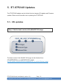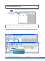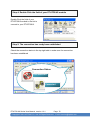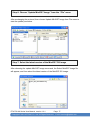
1
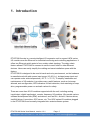
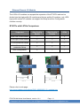
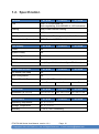
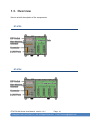
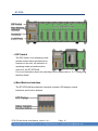
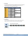
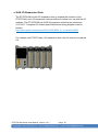
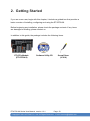
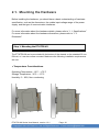
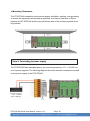
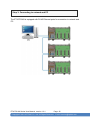
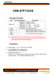
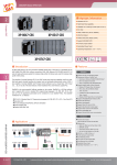
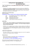
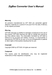
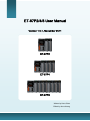
d ET-87P2/4/8 User Manual Version 1.0.1, November 2011 ET-87P2 ET-87P4 ET-87P8 Written by Hans Chen Edited by Anna Huang ET-87P2/4/8 Series User Manual, version 1.0.1 Page: 1 Copyright © 2011 ICP DAS Co., Ltd. All Rights Reserved. Ethernet E-mail: [email protected] Warranty All products manufactured by ICP DAS are under warranty regarding defective materials for a period of one year, beginning from the date of delivery to the original purchaser. Warning ICP DAS assumes no liability for any damage resulting from the use of this product.ICP DAS reserves the right to change this manual at any time without notice. The information furnished by ICP DAS is believed to be accurate and reliable. However, no responsibility is assumed by ICP DAS for its use, not for any infringements of patents or other rights of third parties resulting from its use. Copyright Copyright @ 2011 by ICP DAS Co., Ltd. All rights are reserved. Trademark The names used for identification only may be registered trademarks of their respective companies. Contact US If you have any problem, please feel free to contact us. You can count on us for quick response. Email: [email protected] ET-87P2/4/8 Series User Manual, version 1.0.1 Page: 2 Copyright © 2011 ICP DAS Co., Ltd. All Rights Reserved. Ethernet E-mail: [email protected] Table of Content 1. Introduction ......................................................................... 5 1.1. Features .................................................................................................. 6 1.2. Specification .......................................................................................... 12 1.3. Overview ............................................................................................... 14 1.4. Dimension ............................................................................................. 19 1.5. Companion CD ..................................................................................... 22 2. Getting Started .................................................................. 23 2.1. Mounting the Hardware ......................................................................... 24 2.2. Inserting the I/O Modules ...................................................................... 27 2.3. Configuring the Boot Mode ................................................................... 30 2.3.1. Init Mode ................................................................................................. 31 2.3.2. Lock Mode............................................................................................... 31 2.3.3. Running Mode ......................................................................................... 32 2.4. Installing Tools and Utilities ................................................................... 33 2.5. Assigning a New IP Address ................................................................. 35 2.5.1. Assign a New IP Address Using MiniOS7 Utility ...................................... 36 2.5.2. Using Man-Machine Interface to Assign an IP Address ........................... 40 2.6. Creating Virtual COM Ports Using VxComm Utility............................... 44 2.7. Establishing PC to ET-87P2/4/8 Communications ................................ 49 3. I/O Configuration ............................................................... 52 3.1. Creating the I/O Configuration .............................................................. 53 3.2. Checking the I/O Configuration ............................................................. 57 3.3. Backing up/Restore the I/O Configuration ............................................ 59 3.3.1. Backing up the I/O Configuration ............................................................ 59 ET-87P2/4/8 Series User Manual, version 1.0.1 Page: 3 Copyright © 2011 ICP DAS Co., Ltd. All Rights Reserved. Ethernet E-mail: [email protected] 3.3.2. Restoring/Importing the I/O Configuration ............................................... 60 3.3.3. Restoring/Importing the I/O Configuration and Writing to 87P4/8 ............ 63 3.4. Saving the I/O Configuration File without ET-87P2/4/8 Online ............. 65 4. Tools and SDKs ................................................................. 68 4.1. Tools ...................................................................................................... 69 4.1.1. DCON Utility ............................................................................................ 70 4.1.2. MiniOS7 Utility......................................................................................... 71 4.1.3. VxCOMM Utility ....................................................................................... 72 4.2. SDKs ..................................................................................................... 73 5. ET-87P2/4/8 Updates ......................................................... 74 5.1. OS updates ........................................................................................... 74 5.2. Firmware Updates ................................................................................. 80 Appendix A. Frame Ground.................................................. 86 Appendix B. I/O Configuration Files .................................... 87 Appendix C. Troubleshooting .............................................. 88 Appendix D. Technical Support ........................................... 91 ET-87P2/4/8 Series User Manual, version 1.0.1 Page: 4 Copyright © 2011 ICP DAS Co., Ltd. All Rights Reserved. Ethernet E-mail: [email protected] 1. Introduction ET-87P2/4/8 series is a remote intelligent I/O expansion unit to expand I-87K series I/O modules over the Ethernet for industrial monitoring and controlling applications. It offers two Ethernet switch ports to form a daisy-chain topology. The daisy-chain feature allows ET-87P2/4/8 to connect in series to each other or other Ethernet devices. Users can easily simplify the cabling and save installation space with the feature. ET-87P2/4/8 is designed to be used in harsh and noisy environment, so the hardware is manufactured with wide power input range (10~30 VDC), isolated power input and can operate under wide temperature (-25 °C ~ +75 °C). To simplify installation and maintenance of I/O modules, it provides many useful features, such as: hot swap allowed, auto configuration, LED indicators for fault detection, dual watchdog to keep alive, programmable power on and safe values for safety. There are more than 30 I/O modules supported with the unit, including analog input/output, digital input/output, counter, frequency I/O modules. We provide various software development kits (SDK) and demos, such as DLL, ActiveX, Labview driver, InduSoft driver, Linux driver, OPC server, etc. The I-87K series I/O modules plugged in the ET-87P2/4/8 can be easily integrated into variant software system. ET-87P2/4/8 Series User Manual, version 1.0.1 Page: 5 Copyright © 2011 ICP DAS Co., Ltd. All Rights Reserved. Ethernet E-mail: [email protected] 1.1. Features Here is a summary of the key features which the ET-87Pn offers. Hot Swap Reliable 3-piece construction enables users to hot swap modules during operation, without rewiring. All I/O module data are backed up in the non-volatile memory of the ET-87n. After hot-swapping a module, all settings are automatically loaded to recover. Auto Configuration The I-87K I/O modules can be pre-configured and backed up in the non-volatile memory of the ET-87Pn. When the ET-87Pn is power on or plugged in, the ET-87Pn will automatically checks and restores these configurations to each I-87K I/O modules on it. ET-87P2/4/8 Series User Manual, version 1.0.1 Page: 6 Copyright © 2011 ICP DAS Co., Ltd. All Rights Reserved. Ethernet E-mail: [email protected] Multi-Host Access Simultaneous access by a maximum of 6 host PCs. Although a maximum of 6 host PCs are allowed simultaneous access, it is recommended that fewer host PCs are used in order to give better performance and stability. Easy Duplicate System Using the DON Utility, you can easily make a backup of the I-87K module configurations and write to another ET-87Pn. This design can easily and quickly duplicate many ET-87Pn. Easy Maintenance and Diagnosis The basic configurations (includes IP settings) are set by the push buttons and 7-segment LED display. The operator can easily set the ET-87Pn. And there are several LED status indicators to show whether I-87K modules are configured and work properly. If one I-87K module fails, the operator just needs to replace it with one good I-87K module with the same item number. And then checks the LED indicators to know whether the replacement is performed correctly. The push buttons and LED display design makes it easy for maintenance. There is no PC and Notebook needed. ET-87P2/4/8 Series User Manual, version 1.0.1 Page: 7 Copyright © 2011 ICP DAS Co., Ltd. All Rights Reserved. Ethernet E-mail: [email protected] Various Software Develop Toolkits DLL, ActiveX, Labview driver, Indusoft driver, DasyLab driver, Linux driver. Fully Software Support The free charge software utility and development kits include ● DCON Utility: for configuration ● OPC Servers: OPC is an industrial standard interface based on OLE technology. With the OPC server, I/O modules can be easily build the data logger software without any programming skill. EZ Data Logger EZ Data Logger is the small data logger software. It can be applied to small remote I/O system. With its user-friendly interface, users can quickly and easily build the data logger software without any programming skill. ET-87P2/4/8 Series User Manual, version 1.0.1 Page: 8 Copyright © 2011 ICP DAS Co., Ltd. All Rights Reserved. Ethernet E-mail: [email protected] Communication Daisy-Chain Ethernet topology The ET-87Pn has a built-in two-port Ethernet switch to implement daisy-chain topology. The cabling is much easier and total costs of cable and switch are significantly reduced. LAN Bypass Feature LAN Bypass feature guarantees the Ethernet communication. It will automatically active to continue the network traffic when ET-87Pn lost its power. DCON Protocol I-87K series I/O modules plugged in a ET-87Pn provide a simple command/response protocol (called DCON protocol) for communication. All command/response are in easy used ASCII format. ET-87P2/4/8 Series User Manual, version 1.0.1 Page: 9 Copyright © 2011 ICP DAS Co., Ltd. All Rights Reserved. Ethernet E-mail: [email protected] Rugged Industrial Environment ● Dual Watchdog Design The I-87K series I/O modules provides module watchdog and host watchdog. The module watchdog is a hardware watchdog; the host watchdog is a software watchdog. The module watchdog is designed to automatically reset the microprocessor when the module hangs. The host watchdog monitors the host controller (PC or PLC). The output of module can go to the safe value state when the host fails. ● Programmable Power On Value & Safe Value The DO and AO type I-87K I/O modules provide programmable Power On Value & Safe Value. When ET-87Pn is power on or plugged in, The DO or AO modules output preconfigured Power On Value. When host watchdog is acted, DO or AO modules output preconfigured Safe Vale. ● Wide Range Power Input (10 ~ 30 VDC) ● Wide Range Operating Temperature (-25 ~ +75 °C) ET-87P2/4/8 Series User Manual, version 1.0.1 Page: 10 Copyright © 2011 ICP DAS Co., Ltd. All Rights Reserved. Ethernet E-mail: [email protected] Ethernet Remote I/O Module The I-87Kn I/O modules can support the expansion of the ET-87Pn and can be divided into the high profile I/O modules and the low profile I/O modules, only i-87K high profile series I/O modules can support Hot Swap and Auto-Configuration function correctly. ET-87Pn with I-87Kn Comparison Supported ET-87Pn with Auto Config. Enable ET-87Pn with Auto Config. Disable i-87Kn i-87K Low Profile module -- -- Y i-87K High Profile module Y Y Y i-87K module Hot Swap Y Y -- Auto- Communication parameter Setup Y Y -- Auto-Configuration Y -- -- Low Profile High Profile 81.08 66.7 102.14 87.46 Please refer to web page : http://www.icpdas.com/products/PAC/i-8000/8000_IO_modules.htm ET-87P2/4/8 Series User Manual, version 1.0.1 Page: 11 Copyright © 2011 ICP DAS Co., Ltd. All Rights Reserved. Ethernet E-mail: [email protected] 1.2. Specification Ethernet ET-87P2 ET-87P4 ET-87P8 Port RJ45 * 2, 10/100 Base-TX (Auto-negotiating, Auto MDI/MDI-X, LED indicators) Cabling Daisy-Chain Ethernet Cabling Isolation 3000 VDC ESD Protection +/- 4K contact Discharge and +/- 8K Air Discharge Communication Protocol DCON Protocol (ASCII format) LED Display ET-87P2 ET-87P4 ET-87P8 Power Yes System Ready Yes Auto Configuration Yes Slot Status Yes IP Address Yes (with push buttons to configure IP address) I/O Expansion Slots ET-87P2 ET-87P4 I/O Module Hot Swap Yes Auto Configuration Yes Support Module Type High profile I-87K module only Slots Mechanical Dimension (W x H x D) Environment 2 4 8 ET-87P2 ET-87P4 ET-87P8 126 x 132 x 111 mm 188 x 132 x 111 mm 312 x 132 x 111 mm ET-87P2 ET-87P4 ET-87P8 Operating Temperature -10 ˚C ~ +75 ˚C Storage Temperature -30 ˚C ~ +75 ˚C Humidity 5 ~ 95 %, non- condensing ET-87P2/4/8 Series User Manual, version 1.0.1 Page: 12 Copyright © 2011 ICP DAS Co., Ltd. All Rights Reserved. Ethernet ET-87P8 E-mail: [email protected] Power ET-87P2 Input Range 10 ~ 30 VDC (non-regulated) Redundant Input Yes Reverse polarity protection Yes Isolation 3000 VDC Frame Ground Yes Consumption 2W Power Board Driving 10 ~ 30 VDC (non-regulated) ET-87P2/4/8 Series User Manual, version 1.0.1 ET-87P4 2W 2.4 W Page: 13 Copyright © 2011 ICP DAS Co., Ltd. All Rights Reserved. Ethernet ET-87P8 E-mail: [email protected] 1.3. Overview Here is a brief description of the components. ET-87P2 ET-87P4 ET-87P2/4/8 Series User Manual, version 1.0.1 Page: 14 Copyright © 2011 ICP DAS Co., Ltd. All Rights Reserved. Ethernet E-mail: [email protected] ET-87P8 ● DIP Switch The DIP Switch is an operating mode selector switch which provides three functions in the unit, the selection of operating mode and authorization control for the ET-87P2/4/8. For more information about the operating mode, please refer to “2.3. Configuring the Boot Mode” ● Man-Machine Interface The ET-87P2/4/8 Man-Machine interface includes LED displays, status indicators and function buttons. ET-87P2/4/8 Series User Manual, version 1.0.1 Page: 15 Copyright © 2011 ICP DAS Co., Ltd. All Rights Reserved. Ethernet E-mail: [email protected] LED Displays The LED displays (5-Dgital 7-Segment LEDs) show the I/O configuration error, warning status or IP settings. Status Indicators The indicators indicate which the parameter is displayed in LED displays and whether the power is on or not. Status Indicator Description IP The IP indicator indicates the IP address which is displayed in LED displays. Mask The Mask indicator indicates the Mask which is displayed in LED displays. Gateway The Gateway indicator indicates the Gateway which is displayed in LED displays. Power The Power indicator indicates whether power is on or not. Function Buttons The function buttons allow the user to navigate through the configuration and or adjusting set-points. Function Button Description Mode The Mode button switches to the configuration mode. If already in configuration mode, the set-point will move to the next configuration parameter. UP In configuration mode, the UP key scrolls through the parameter value, and can increase the parameter values. Down In configuration mode, the Down key scrolls through the parameter value, and can decrease the parameter values. SET The SET button shows the parameter values in the LED display. If in configuration mode, the SET button will move the set-point. ET-87P2/4/8 Series User Manual, version 1.0.1 Page: 16 Copyright © 2011 ICP DAS Co., Ltd. All Rights Reserved. Ethernet E-mail: [email protected] ● Connector The connector provides an interface for supplying power to the unit, exchanging data between the unit and PC or external device, and grounding the unit. The pin assignments of the connector are as follows: Pin Signal 1 PWR1 2 P.GND 3 PWR2 4 P.GND 5 N.C. 6 GND 7 TxD 8 RxD 9 F.G. Description PWR1 PWR2 Unassigned RS-232 Frame Ground ● 2 LAN Ports The ET-87P2/4/8 has two Ethernet ports. One port is used to interface with a network, and other is used as a router to set up a daisy chain topology. ET-87P2/4/8 Series User Manual, version 1.0.1 Page: 17 Copyright © 2011 ICP DAS Co., Ltd. All Rights Reserved. Ethernet E-mail: [email protected] ● 2/4/8 I/O Expansion Slots The ET-87P2/4/8 has 4/8 I/O expansion slots to expand the functions of the ET-87P2/4/8, each I/O expansion slots has different numbers for use with the I/O modules. The ET-87P2/4/8 has 2/4/8 I/O expansion slots that are numbered 0-1/0-3/0-7. Complete I/O module specifications and wiring diagrams can be found in http://www.icpdas.com/products/PAC/i-8000/8000_IO_modules.htm#i87 For example, the ET-87P4 has 4 I/O expansion slots, the I/O slots are numbered 0-4. ET-87P2/4/8 Series User Manual, version 1.0.1 Page: 18 Copyright © 2011 ICP DAS Co., Ltd. All Rights Reserved. Ethernet E-mail: [email protected] 1.4. Dimension The diagrams below provide the dimensions of the ET-87P2/4/8 to use in defining your enclosure specifications. Remember to leave room for potential expansion if you are using other components in your system. The height dimension is the same for all ET-87P2/4/8. The width depending on your choose of I/O expansion slots. All dimensions are in millimeters. ET-87P2 ET-87P2/4/8 Series User Manual, version 1.0.1 Page: 19 Copyright © 2011 ICP DAS Co., Ltd. All Rights Reserved. Ethernet E-mail: [email protected] ET-87P4 ET-87P2/4/8 Series User Manual, version 1.0.1 Page: 20 Copyright © 2011 ICP DAS Co., Ltd. All Rights Reserved. Ethernet E-mail: [email protected] ET-87P8 ET-87P2/4/8 Series User Manual, version 1.0.1 Page: 21 Copyright © 2011 ICP DAS Co., Ltd. All Rights Reserved. Ethernet E-mail: [email protected] 1.5. Companion CD This package comes with a CD that provides drivers, software utility, all of the required documentations…, etc. All of them are listed below. CD:\NAPDOS 87pn_io_unit ET-87Pn Document Firmware OS_Image PC_Tool DCON_Utility MiniOS7_Utility VxComm_Utiltiy ET-87P2/4/8 Series User Manual, version 1.0.1 Page: 22 Copyright © 2011 ICP DAS Co., Ltd. All Rights Reserved. Ethernet E-mail: [email protected] 2. Getting Started If you are a new user, begin with this chapter, it includes a guided tour that provides a basic overview of installing, configuring and using the ET-87P2/4/8. Before beginning any installation, please check the package contents. If any items are damaged or missing, please contact us. In addition to this guide, the package includes the following items: ET-87Pn Module (ET-87P2/4/8) Software Utility CD ET-87P2/4/8 Series User Manual, version 1.0.1 Screw Driver (1C016) Page: 23 Copyright © 2011 ICP DAS Co., Ltd. All Rights Reserved. Ethernet E-mail: [email protected] 2.1. Mounting the Hardware Before installing the hardware, you should have a basic understanding of hardware specification, such as the dimensions, the usable input-voltage range of the power supply, and the type of communication interfaces. For more information about the hardware details, please refer to “1.1. Specifications” For more information about the hardware dimensions, please refer to “1.3. Dimension” Step 1: Mounting the ET-87P2/4/8 The ET-87P2/4/8 can be mounted with the bottom of the chassis on the standard 35 mm DIN rail, or it can be surface mounted. Make sure the following installation requirements are met. Temperature Considerations. Operating Temperature: -10˚C ~ +75˚C Storage Temperature: -30˚C ~ +75˚C Humidity: 5 ~ 95%, Non-condensing ET-87P2/4/8 Series User Manual, version 1.0.1 Page: 24 Copyright © 2011 ICP DAS Co., Ltd. All Rights Reserved. Ethernet E-mail: [email protected] ● Mounting Clearances The ET-87P2/4/8 installation must provide proper ventilation, spacing, and grounding to ensure the equipment will operate as specified. A minimum clearance of 50mm between the ET-87P2/4/8 and the top and bottom side of the enclosure panels must be provided. Step 2: Connecting to power supply The ET-87P2/4/8 has redundant power, you can be powered by +10 ~ +30 VDC via one of power supplies. The following diagram shows the terminal connections located on the power supply of the ET-87P2/4/8. ET-87P2/4/8 Series User Manual, version 1.0.1 Page: 25 Copyright © 2011 ICP DAS Co., Ltd. All Rights Reserved. Ethernet E-mail: [email protected] Step 3: Connecting to network and PC The ET-87P2/4/8 is equipped with RJ-45 Ethernet ports for connection to network and PC ET-87P2/4/8 Series User Manual, version 1.0.1 Page: 26 Copyright © 2011 ICP DAS Co., Ltd. All Rights Reserved. Ethernet E-mail: [email protected] 2.2. Inserting the I/O Modules The ET-87P2/4/8 has 4/8 I/O expansion slots to expand the functions of the ET-87P2/4/8, allowing it to communicate with external I/O modules, and before choosing the right I/O modules, you first need to know the I/O expansion capacities in order to choose the best expansion module for achieving maximal efficiency. There are more than 30 high profile I/O modules available for interfacing many different measurements, including thermocouple, voltage, RTD, current, resistance, strain, digital,…, etc., and these modules have their own manuals, so if you are using them you should supplement this manual with the manual specifically designed for the special module. For more information about the I/O expansion modules that are compatible with the ET-87P2/4/8, please refer to http://www.icpdas.com/products/PAC/i-8000/8000_IO_modules.htm#i87 Tips & Warnings The ET-87Pn only can support the high profile I/O modules. ET-87P2/4/8 Series User Manual, version 1.0.1 Page: 27 Copyright © 2011 ICP DAS Co., Ltd. All Rights Reserved. Ethernet E-mail: [email protected] Step 1: Align circuit card with slot and press firmly to seat module into connector Step 2: Pull top and bottom locking tabs toward module face. Click indicates lock is engaged. ET-87P2/4/8 Series User Manual, version 1.0.1 Page: 28 Copyright © 2011 ICP DAS Co., Ltd. All Rights Reserved. Ethernet E-mail: [email protected] Step 3: Wiring the I/O modules to the monitored Inputs and Voltages ET-87P2/4/8 Series User Manual, version 1.0.1 Page: 29 Copyright © 2011 ICP DAS Co., Ltd. All Rights Reserved. Ethernet E-mail: [email protected] 2.3. Configuring the Boot Mode The ET-87P2/4/8 can be configured in three modes of operation to provide has three operating modes that can be determined through a DIP switch. Switch Position Init Mode of Operation Init Mode Lock Lock Mode Run Running Mode ET-87P2/4/8 Series User Manual, version 1.0.1 Description OS cannot execute autoexec.bat Flash can be read/write OS can execute autoexec.bat Flash is read only (lock) OS can execute autoexec.bat Flash can be read/write Page: 30 Copyright © 2011 ICP DAS Co., Ltd. All Rights Reserved. Ethernet E-mail: [email protected] 2.3.1. Init Mode Init mode is used to update the OS image and upgrade the firmware. If dip switch is set as Init mode and reset the power, the ET-87P2/4/8 cannot boot up with autoexec.bat and will enter OS operation mode, in this case there is no program running on the ET-87P2/4/8 and the 5-digital 7-SEG LEDs will count the number as shown below: 2.3.2. Lock Mode The lock mode prevents the data from being programmed in the memory unless an unlock sequence precedes the loading of the data that is to be programmed into the memory ET-87P2/4/8 Series User Manual, version 1.0.1 Page: 31 Copyright © 2011 ICP DAS Co., Ltd. All Rights Reserved. Ethernet E-mail: [email protected] 2.3.3. Running Mode The running mode represents there is the program running on the ET-87P2/4/8 and the 5-digits 7-SEG LEDs will show the message according to the running program, but if during this time there is another program running on ET-87P2/4/8, the 5-digits 7-SEG LEDs isn’t managed with this program, it will stop motion at the present state. ET-87P2/4/8 Series User Manual, version 1.0.1 Page: 32 Copyright © 2011 ICP DAS Co., Ltd. All Rights Reserved. Ethernet E-mail: [email protected] 2.4. Installing Tools and Utilities Following tools and utilities has been installed on the system: MiniOS7 Utility The MiniOS7 Utility is a comprehensive suite of software tools that helps you update OS image or firmware, configure Ethernet settings, and download files to ET-87P2/4/8 from PC. For more detailed information on how to update the firmware and OS, please refer to “5. ET-87P2/4/8 Updates” The MiniOS7 Utility can be obtained from companion CD or our FTP site: CD:\Napdos\minios7\utility\minios7_utility\ ftp://ftp.icpdas.com/pub/cd/8000cd/napdos/minios7/utility/minios7_utility/ VxComm Utility The VxComm Utility has the ability to create virtual COM ports that are actually TCP/IP port connections. This means that any software designed to communicate with RS-232 ports can now communicate over Ethernet or Internet TCP/IP ports The VxComm Utility can be obtained from companion CD or our FTP site: CD:\Napdos\driver\vxcomm_driver\ ftp://ftp.icpdas.com/pub/cd/8000cd/napdos/driver/vxcomm_driver/ ET-87P2/4/8 Series User Manual, version 1.0.1 Page: 33 Copyright © 2011 ICP DAS Co., Ltd. All Rights Reserved. Ethernet E-mail: [email protected] DCON Utility DCON Utility is a tool that allows you to easily and quickly monitor, manage and configure the I/O expansion modules. The DCON Utility can be obtained from companion CD or our FTP site: CD:\Napdos\driver\dcon_utility\ ftp://ftp.icpdas.com/pub/cd/8000cd/napdos/driver/dcon_utility/ ET-87P2/4/8 Series User Manual, version 1.0.1 Page: 34 Copyright © 2011 ICP DAS Co., Ltd. All Rights Reserved. Ethernet E-mail: [email protected] 2.5. Assigning a New IP Address The ET-87P2/4/8 is Ethernet I/O unit, which comes with a default IP address. Therefore, you must first assign a new IP address and the subnet mask and gateway for this IP address to ET-87P2/4/8 on your network. The factory default IP settings are as follows: Item Default IP Address 192.168.255.1 Subnet Mask 255.255.0.0 Gateway 192.168.0.1 The IP settings of the ET-87P2/4/8 can be set in one of three ways. Using MiniOS7 Utility Use ET-87P2/4/8 Web Site Use Man-Machine Interface ET-87P2/4/8 Series User Manual, version 1.0.1 Page: 35 Copyright © 2011 ICP DAS Co., Ltd. All Rights Reserved. Ethernet E-mail: [email protected] 2.5.1. Assign a New IP Address Using MiniOS7 Utility MiniOS7 Utility is an easy-to-use network configuration Utility. You can configure the ET-87P2/4/8 to connect to a LAN by using it. Step 1: Reboot the ET-87P2/4/8 at Run mode Make sure the switch is set to the “Run” position before you boot up the ET-87P2/4/8. Step 2: Run the MiniOS7 Utility Double-click the MiniOS7 Utility shortcut on your desktop. ET-87P2/4/8 Series User Manual, version 1.0.1 Page: 36 Copyright © 2011 ICP DAS Co., Ltd. All Rights Reserved. Ethernet E-mail: [email protected] Step 3: Choose “Search” from the “Connection” menu After choosing Search from Connection menu, that will search all of the MiniOS7 modules on your network. See the status tip, waiting for the search to be done. Step 4: Choose the field “192.168.255.1” from the list and then Press “IP setting” button from the toolbar Choose default value “192.168.255.1” for fields in the list, and then choose IP setting from the toolbar. 2 1. Choose the field “192.168.255.1” ET-87P2/4/8 Series User Manual, version 1.0.1 Page: 37 Copyright © 2011 ICP DAS Co., Ltd. All Rights Reserved. Ethernet E-mail: [email protected] Step 5: Assign a new IP address and then choose “Set” button You can manually assign an IP address or use DHCP to dynamically assign IP addresses Step 6: Choose “Yes” button After completing the settings, the Confirm dialog box will appear, and then choose the Yes button to exit the procedure. ET-87P2/4/8 Series User Manual, version 1.0.1 Page: 38 Copyright © 2011 ICP DAS Co., Ltd. All Rights Reserved. Ethernet E-mail: [email protected] Step 7: Reboot the module and then choose “Search” from the “Connection” menu to check the IP setting After completing the settings, you can reboot the module and then using MiniOS7 to search module again for making sure that your IP settings are correct. ET-87P2/4/8 Series User Manual, version 1.0.1 Page: 39 Copyright © 2011 ICP DAS Co., Ltd. All Rights Reserved. Ethernet E-mail: [email protected] 2.5.2. Using Man-Machine Interface to Assign an IP Address The ET-87P2/4/8 Man-Machine Interface consists of an operator panel. You can configure an IP address without any computer. Step 1: Reboot the ET-87P2/4/8 at Run mode Make sure the switch is set to the “Run” position before you boot up the ET-87P2/4/8. ET-87P2/4/8 Series User Manual, version 1.0.1 Page: 40 Copyright © 2011 ICP DAS Co., Ltd. All Rights Reserved. Ethernet E-mail: [email protected] Step 2: Push MODE button to entry control and then use control buttons to configure IP address Entry control After push the Mode button, then start configure the IP settings and remote I/O port number. In this case, the LED displays show the IP address as 192.168.255.1 and the port number as 9999. IP Address (192.168.255.1) Remote I/O port number (9999) Control buttons descrition MODE: Skip to the configure the subnet mask UP: Increase the value DOWN: Reduce the value SET: Save the configuration and skip to the next point ET-87P2/4/8 Series User Manual, version 1.0.1 Page: 41 Copyright © 2011 ICP DAS Co., Ltd. All Rights Reserved. Ethernet E-mail: [email protected] After completing the IP address and port number configuring the port number, please push the MODE button to skip to configure the subnet Mask. In this case, the LED displays show the subnet Mask as 255.255.0.0. Subnet Mask (255.255.0.0) Control buttons descrition MODE: Skip to the configure the gateway UP: Increase the value DOWN: Reduce the value SET: Save the configuration and skip to the next point After completing the mask configuring the port number, please push the MODE button to skip to configure the subnet Mask. In this case, the LED displays show the Gateway as 192.168.0.1. Gateway Control buttons descrition MODE: Skip to the configure the gateway UP: Increase the value DOWN: Reduce the value SET: Save the configuration and skip to the next point ET-87P2/4/8 Series User Manual, version 1.0.1 Page: 42 Copyright © 2011 ICP DAS Co., Ltd. All Rights Reserved. Ethernet E-mail: [email protected] Step 3: Stop the action and wait a while until 5-digital 7-SEG LEDs automatically shows the IP settings Stop the action about ten seconds, the settings will be changed and displayed in 5 digital LEDs twice. Step 4: Push the SET button to check the IP settings If you don’t have to check the IP settings, you just push the SET button, the 5 digital LEDs will show the IP settings twice. ET-87P2/4/8 Series User Manual, version 1.0.1 Page: 43 Copyright © 2011 ICP DAS Co., Ltd. All Rights Reserved. Ethernet E-mail: [email protected] 2.6. Creating Virtual COM Ports Using VxComm Utility The ET-87P2/4/8 is equipped with two Ethernet ports. You can be sent and received RS-232 series data across the Ethernet ports by creating virtual COM ports.. Step 1: Run the VxComm Utility Double-click the VxComm Utility shortcut on your desktop. ET-87P2/4/8 Series User Manual, version 1.0.1 Page: 44 Copyright © 2011 ICP DAS Co., Ltd. All Rights Reserved. Ethernet E-mail: [email protected] Step 2: Press “Search Servers” button from the toolbar After pressing Search Servers from toolbar, that will search all of your network modules. Press the “Search Servers” ET-87P2/4/8 Series User Manual, version 1.0.1 Page: 45 Copyright © 2011 ICP DAS Co., Ltd. All Rights Reserved. Ethernet E-mail: [email protected] Step 3: Choose the IP Address field you specified easier and press “Add Server(s)” button from the toolbar Choose the IP Address field you specified in the list, and then press Add Server(s) from the toolbar. 2 1. Choose the IP Address field you specified ET-87P2/4/8 Series User Manual, version 1.0.1 Page: 46 Copyright © 2011 ICP DAS Co., Ltd. All Rights Reserved. Ethernet E-mail: [email protected] Step 4: Choose the Valid COM Port number you wish to use After choosing Add Server(s) , the Adding Servers dialog box will appear, and then do the following in this order: i. Choose the valid COM Port ii. Check the “Maps virtual COM ports to “Port I/O” on servers” iii. Click OK button 1. Choose the COM Port name you wish to use 2 ET-87P2/4/8 Series User Manual, version 1.0.1 3 Page: 47 Copyright © 2011 ICP DAS Co., Ltd. All Rights Reserved. Ethernet E-mail: [email protected] Step 5: Press “Exit” button form the toolbar and then restart the driver After completing the settings, press Exit button to restart the driver for effecting the settings. ET-87P2/4/8 Series User Manual, version 1.0.1 Page: 48 Copyright © 2011 ICP DAS Co., Ltd. All Rights Reserved. Ethernet E-mail: [email protected] 2.7. Establishing PC to ET-87P2/4/8 Communications DCON Utility is an easy-to-use I/O configuration Utility. Before configuring any I/O settings, you need first establish a connection between ET-87P2/4/8 and PC. Step 1: Run the DCON Utility Double-click the DCON Utility shortcut on your desktop. ET-87P2/4/8 Series User Manual, version 1.0.1 Page: 49 Copyright © 2011 ICP DAS Co., Ltd. All Rights Reserved. Ethernet E-mail: [email protected] Step 2: Press “COM Port” from the menu to configure the searching parameters After pressing COM Port from the menu, a dialog will appear, to configure the searching parameters as follows: Form COM to search Baud Rate Option Checksum Option Parity Option Parameter As name you created by VxComm Utility Any baud rate options you can choose Disable None (N,8,1) ET-87P2/4/8 Series User Manual, version 1.0.1 Page: 50 Copyright © 2011 ICP DAS Co., Ltd. All Rights Reserved. Ethernet E-mail: [email protected] Step 3: Press “ After pressing ” from the toolbar from toolbar, that will search all modules are available. See the status tip, waiting for the search to be done. Step 4: The connection has been successfully completed After the search has been done, the name of the ET-87P2/4/8 will display in the list. The address of the ET-87P2/4/8 is always the 1. ET-87P2/4/8 Series User Manual, version 1.0.1 Page: 51 Copyright © 2011 ICP DAS Co., Ltd. All Rights Reserved. Ethernet E-mail: [email protected] 3. I/O Configuration The ET-87P2/4/8 automatically detects any installed I/O modules at power up. Before communicating with the I/O module, we must first create the I/O configuration to ET-87P2/4/8 for initiating the I/O modules. For more information on how to create the I/O configuration, please refer to “3.1. Creating the I/O Configuration” The status of the I/O configuration The LED displays can be used to indicate the status of the I/O configuration. By this feature, you can detect the indicator position of the displayed element is shown below. For more information about the fault message of the I/O slots, please refer to “3.2.1. Fault Message Display” S (n) represents the slot number. (Slot 0 ~ Slot 7) After Inserting the I/O module, the status of the I/O configuration will start flashing until the I/O configuration is correctly written to ET-87P2/4/8. If the I/O configuration fails, the status of the I/O configuration will always on. ET-87P2/4/8 Series User Manual, version 1.0.1 Page: 52 Copyright © 2011 ICP DAS Co., Ltd. All Rights Reserved. Ethernet E-mail: [email protected] 3.1. Creating the I/O Configuration DCON Utility is easy-to-use tool that allows user to automatically check and configure all of I/O configurations. Step 1: Establishing a connection between the ET-87P2/4/8 and PC For more detailed information about this process, please refer to section “2.7. Establishing a connection between ET-87P2/4/8 and PC using DCON Utility” Step 2: Click the name of the ET-87P2/4/8 from the list and then choose the “Configure Module” After clicking the name of the ET-87P2/4/8 from the list, a dialog will appear, then choose the “Configure Module” button ET-87P2/4/8 Series User Manual, version 1.0.1 Page: 53 Copyright © 2011 ICP DAS Co., Ltd. All Rights Reserved. Ethernet E-mail: [email protected] Step 3: Choose “Set As Scanned” button After choosing Configure Module button, the configuration form will appear, and display all found I/O module, then choose the Set As Scanned button to define the found I/O module. The yellow color indicates the I/O module is undefined. After choosing the Set As Scanned button, the found I/O module name will appear in the first column of each item. ET-87P2/4/8 Series User Manual, version 1.0.1 Page: 54 Copyright © 2011 ICP DAS Co., Ltd. All Rights Reserved. Ethernet E-mail: [email protected] Step 4: Choose “Configuration” button After choosing the Set As Scanned button, then you can click the configuration button of each found I/O module to configure the I/O module. ET-87P2/4/8 Series User Manual, version 1.0.1 Page: 55 Copyright © 2011 ICP DAS Co., Ltd. All Rights Reserved. Ethernet E-mail: [email protected] Step 5: Choose “Write To 87P4/8” button After configuring the I/O module, you must click the Write To 87P4/8 button, then the Warning dialog will appear, and then click Yes button to continue effecting the settings, The I/O configuration will be written to ET-87P2/4/8. ET-87P2/4/8 Series User Manual, version 1.0.1 Page: 56 Copyright © 2011 ICP DAS Co., Ltd. All Rights Reserved. Ethernet E-mail: [email protected] 3.2. Checking the I/O Configuration The monitor mode and the configuration mode are separated in order to prevent the user to accidentally make any changes in settings. Step 1: Establishing a connection between the ET-87P2/4/8 and PC For more detailed information about this process, please refer to section “2.7. Establishing a connection between ET-87P2/4/8 and PC using DCON Utility” Step 2: Choose the name of the ET-87P2/4/8 from the list and then choose the “Check Module Status” After clicking the name of the ET-87P2/4/8 from the list, a dialog will appear, then choose the “Check Module Status” button ET-87P2/4/8 Series User Manual, version 1.0.1 Page: 57 Copyright © 2011 ICP DAS Co., Ltd. All Rights Reserved. Ethernet E-mail: [email protected] Step 3: Choose “Status” button After choosing Check Module Status button, a dialog will appear, and display all configured I/O modules, and then choose the status button one of the I/O configuration that you want to monitor. ET-87P2/4/8 Series User Manual, version 1.0.1 Page: 58 Copyright © 2011 ICP DAS Co., Ltd. All Rights Reserved. Ethernet E-mail: [email protected] 3.3. Backing up/Restore the I/O Configuration The configuration file is a custom INI file that can be used to backup and restore the ET-87P2/4/8, or import another ET-87P2/4/8. 3.3.1. Backing up the I/O Configuration After configuring and writing to ET-87P2/4/8, you can saving the configuration. This function can be useful if you need to make backups of ET-87P2/4/8. ET-87P2/4/8 Series User Manual, version 1.0.1 Page: 59 Copyright © 2011 ICP DAS Co., Ltd. All Rights Reserved. Ethernet E-mail: [email protected] 3.3.2. Restoring/Importing the I/O Configuration Once you have saved a configuration file of the ET-87P2/4/8, you can use this option to restore the ET-87P2/4/8, or import to another ET-87P2/4/8. Step 1: Choose Load Configuration button After choosing the Load Configuration button, the Open dialog will appear. ET-87P2/4/8 Series User Manual, version 1.0.1 Page: 60 Copyright © 2011 ICP DAS Co., Ltd. All Rights Reserved. Ethernet E-mail: [email protected] Step 2: Choose the I/O configuration file you wish to use After choosing the Load Configuration button, the Open will appear, and then select the I/O configuration file you wish to use. ET-87P2/4/8 Series User Manual, version 1.0.1 Page: 61 Copyright © 2011 ICP DAS Co., Ltd. All Rights Reserved. Ethernet E-mail: [email protected] Step 3: The configuration parameters have been loaded successfully ET-87P2/4/8 Series User Manual, version 1.0.1 Page: 62 Copyright © 2011 ICP DAS Co., Ltd. All Rights Reserved. Ethernet E-mail: [email protected] 3.3.3. Restoring/Importing the I/O Configuration and Writing to 87P4/8 If you sure the contents of the configure file is what you need, here you can simply load the configuration and write to 87Pn at the same time. Step 1: Choose Load Configuration And Write To 87PX button After choosing the Load Configuration And Write to 87PX button, the Open dialog will appear. ET-87P2/4/8 Series User Manual, version 1.0.1 Page: 63 Copyright © 2011 ICP DAS Co., Ltd. All Rights Reserved. Ethernet E-mail: [email protected] Step 2: Choose the I/O configuration file you wish to use After choosing the Load Configuration button, the Open will appear, and then select the I/O configuration file you wish to use. ET-87P2/4/8 Series User Manual, version 1.0.1 Page: 64 Copyright © 2011 ICP DAS Co., Ltd. All Rights Reserved. Ethernet E-mail: [email protected] 3.4. Saving the I/O Configuration File without ET-87P2/4/8 Online DCON Utility can save the ET-87P2/4/8 I/O configuration file without connect ET-87P2/4/8 and any I/O modules. You may use this function to create the configuration file. It is convenient for remote support and system backup. Step 1: Press “ After pressing and Checksum. ” from the toolbar from toolbar, and then select the Module ID, Address, Baudrate ET-87P2/4/8 Series User Manual, version 1.0.1 Page: 65 Copyright © 2011 ICP DAS Co., Ltd. All Rights Reserved. Ethernet E-mail: [email protected] Step 2: Choose the “Configure Module” After completing the off-line configuration, the I/O Configuration form will appear, and then choose the Configure Module button. Step 3: Configure the I/O module Select and configure the I/O module, then save the settings as another file name. 1 ET-87P2/4/8 Series User Manual, version 1.0.1 2 Page: 66 Copyright © 2011 ICP DAS Co., Ltd. All Rights Reserved. Ethernet E-mail: [email protected] Step 4: Choose “Save Configuration” button After choosing Save Configuration button, the Save As… dialog will appear, and the type the file name. ET-87P2/4/8 Series User Manual, version 1.0.1 Page: 67 Copyright © 2011 ICP DAS Co., Ltd. All Rights Reserved. Ethernet E-mail: [email protected] 4. Tools and SDKs This chapter brief describes the function of installed tools and SDKs. All of the tools and SDKs are listed below. deference CD:\NAPDOS 87pn_io_unit ET-87Pn PC_Tool DCON_Utility MiniOS7_Utility VxComm_Utility Driver DCON_ActiveX DCON_ActiveX_New DCON_DasyLab DCON_DDE DCON_DLL DCON_DLL_New DCON_GWBasic DCON_InduSoft DCON_LabVIEW DCON_Linux DCON_Utility EZ_Data_Logger VxComm_Driver ET-87P2/4/8 Series User Manual, version 1.0.1 Page: 68 Copyright © 2011 ICP DAS Co., Ltd. All Rights Reserved. Ethernet E-mail: [email protected] 4.1. Tools There are three main tools for managing the ET-87P2/4/8. All of tools are list below. CD:\NAPDOS 87pn_io_unit ET-87Pn PC_Tool DCON_Utility MiniOS7_Utility VxComm_Utiltiy The following lists summarize the functions of these tools. DCON Utility Configure I/O modules (Please refer to 3. I/O Configuration) MiniOS7 Utility Configure IP Address (Please refer to 2.3.2. Assign IP Address) Update the OS (Please refer to 4.1.2.2. Updating the ET-87P2/4/8 OS) Update the firmware (Please refer to 4.1.2.3. Updating the ET-87P2/4/8 firmware) VxComm Utility Create Virtual COM Ports (Please refer to 2.4.2. Creating Virtual COM Ports) ET-87P2/4/8 Series User Manual, version 1.0.1 Page: 69 Copyright © 2011 ICP DAS Co., Ltd. All Rights Reserved. Ethernet E-mail: [email protected] 4.1.1. DCON Utility The DCON Utility is a toolkit that help user search the network, easily to Configure the I/O modules and test the I/O status via the serial port (RS-232/485) or Ethernet port (using virtual com port). It supports not only the DCON Protocol I/O modules but also the M Series I/O Modules (Modbus RTU M-7K, M-87K and will support Modbus ASCII M-87K) now. For more detailed information on DCON Utility applications, please refer to “3. I/O configuration” For more details, please refer to DCON Utility web site: http://www.icpdas.com/products/dcon/introduction.htm ET-87P2/4/8 Series User Manual, version 1.0.1 Page: 70 Copyright © 2011 ICP DAS Co., Ltd. All Rights Reserved. Ethernet E-mail: [email protected] 4.1.2. MiniOS7 Utility MiniOS7 Utility is a tool for uploading firmware to flash memory and updating the OS to ET-87P2/4/8 module embedded with ICP DAS MiniOS7 with easiness and quickness. Note: Since version 3.1.1, the Utility can allow users remotely access the controllers (7188E, 8000E, …, etc) through the Ethernet For more detailed information on how to using MiniOS7 Utility to assign an IP addess, please refer to “2.5.1. Using MiniOS7 Utility to assign a new IP” For more detailed information on how to using MiniOS7 Utility to update the ET-87P2/4/8, please refer to “5. ET-87P2/4/8 Updates” ET-87P2/4/8 Series User Manual, version 1.0.1 Page: 71 Copyright © 2011 ICP DAS Co., Ltd. All Rights Reserved. Ethernet E-mail: [email protected] 4.1.3. VxCOMM Utility The VxComm Utility is designed for creating virtual COM ports and maps them to the Ethernet port of the ET-87P2/4/8. Commands and data sending to the virtual COM ports will be redirected to the ET-87P2/4/8’s Ethernet ports. And the received data from ET-87P2/4/8's COM ports will also be redirected to PC's virtual COM ports. For more detailed information on how to create virtual COM ports, please refer to “2.4. Using VxComm Utility to Create Virtual COM Ports” For more details, please refer to VxComm Utility web site: http://www.icpdas.com/products/Software/VxComm/vxcomm.htm ET-87P2/4/8 Series User Manual, version 1.0.1 Page: 72 Copyright © 2011 ICP DAS Co., Ltd. All Rights Reserved. Ethernet E-mail: [email protected] 4.2. SDKs The ICP DAS SDKs is a set of tools, code samples, documentation, headers, and libraries that users can use to create applications quickly and easily. All of them are list below. CD:\NAPDOS Driver DCON_ActiveX DCON_ActiveX_New DCON_DasyLab DCON_DDE DCON_DLL DCON_DLL_New DCON_GWBasic DCON_InduSoft DCON_LabVIEW DCON_Linux DCON_Utility EZ_Data_Logger VxComm_Driver For details of the function and example applications of the ET-87P2/4/8, please refer to: http://www.icpdas.com/products/dcon/introduction.htm http://ftp.icpdas.com/pub/cd/8000cd/napdos/driver/ ET-87P2/4/8 Series User Manual, version 1.0.1 Page: 73 Copyright © 2011 ICP DAS Co., Ltd. All Rights Reserved. Ethernet E-mail: [email protected] 5. ET-87P2/4/8 Updates The ET-87P2/4/8 updates can be divided into two classes: OS updates and Firmware updates. Below we will describe how to updating the ET-87P2/4/8. 5.1. OS updates Step 1: Get the latest version of the MiniOS7 OS image C837_2M_UDP_YYYYMMDD.img The latest version of the MiniOS7 OS image can be obtained from: CD:\NAPDOS\87pn_io_unit\ET-87Pn\OS_Image\ ftp://ftp.icpdas.com/pub/cd/8000cd/napdos/87pn_io_unit/et-87pn/os_image/ ET-87P2/4/8 Series User Manual, version 1.0.1 Page: 74 Copyright © 2011 ICP DAS Co., Ltd. All Rights Reserved. Ethernet E-mail: [email protected] Step 2: Run the MiniOS7 Utility Double-click the MiniOS7 Utility shortcut on your desktop. Step 3: Choose “Search” from the “Connection” menu After choosing Search from Connection menu, that will search all of the MiniOS7 modules on your network. See the status tip, waiting for the search to be done. ET-87P2/4/8 Series User Manual, version 1.0.1 Page: 75 Copyright © 2011 ICP DAS Co., Ltd. All Rights Reserved. Ethernet E-mail: [email protected] Step 4: Double-Click the field of your ET-87P2/4/8 module Double-Click the field of your ET-87P2/4/8 module in the list to connect to your ET-87P2/4/8. Step 5: The connection has ready been established Check the connection status in the top right side to make sure the connection has been established Connection Status Disconnected Connected ET-87P2/4/8 Series User Manual, version 1.0.1 Page: 76 Copyright © 2011 ICP DAS Co., Ltd. All Rights Reserved. Ethernet E-mail: [email protected] Step 6: Choose “Update MiniOS7 Image” from the “File” menu After exchanging the protocol, then choose Update MiniOS7 Image from File menu to start the update procedure. Step 7: Select the latest version of the MiniOS7 OS image After choosing the update MiniOS7 Image command, the Select MiniOS7 Image file will appear, and then select the latest version of the MiniOS7 OS image. ET-87P2/4/8 Series User Manual, version 1.0.1 Page: 77 Copyright © 2011 ICP DAS Co., Ltd. All Rights Reserved. Ethernet E-mail: [email protected] Step 8: Click “OK” to finish the procedure After confirming the command, you just need to wait awhile until the following dialog appear, and then click OK button to finish the procedure. Step 9: Restart the MiniOS7 Utility and establish a connection You may need to restart the MiniOS7 Utility for refreshing the settings, and then establishing a connection. For more detailed about this process, please refer to section “4.1.2.1. Establishing a Connection” to establish a connection. ET-87P2/4/8 Series User Manual, version 1.0.1 Page: 78 Copyright © 2011 ICP DAS Co., Ltd. All Rights Reserved. Ethernet E-mail: [email protected] Step 10: Choose “Info” from the “Command” menu to check the OS version After pressing F7 or choosing info from Command menu to check the OS version. Check the Build item ET-87P2/4/8 Series User Manual, version 1.0.1 Page: 79 Copyright © 2011 ICP DAS Co., Ltd. All Rights Reserved. Ethernet E-mail: [email protected] 5.2. Firmware Updates The firmware is stored in flash memory and can be updated to fix functionality issues or add additional features, so we advise you to periodically check the ICP DAS web site for the latest updates. Step 1: Get the latest version of the MiniOS7 firmware and the autoexec.bat file The latest version of the MiniOS7 firmware and autoexec.bat file can be obtained from: CD:\NAPDOS\87pn_io_unit\ET-87Pn\Firmware\ ftp://ftp.icpdas.com/pub/cd/8000cd/napdos/87pn_io_unit/et-87pn/firmware/ Step 2: Run the MiniOS7 Utility Double-click the MiniOS7 Utility shortcut on your desktop. ET-87P2/4/8 Series User Manual, version 1.0.1 Page: 80 Copyright © 2011 ICP DAS Co., Ltd. All Rights Reserved. Ethernet E-mail: [email protected] Step 3: Choose “Search” from the “Connection” menu After choosing Search from Connection menu, that will search all of the MiniOS7 modules on your network. See the status tip, waiting for the search to be done. Step 4: Double-Click the field of your ET-87P2/4/8 module Double-Click the field of your ET-87P2/4/8 module in the list to connect to your ET-87P2/4/8. ET-87P2/4/8 Series User Manual, version 1.0.1 Page: 81 Copyright © 2011 ICP DAS Co., Ltd. All Rights Reserved. Ethernet E-mail: [email protected] Step 5: The connection has ready been established Check the connection status in the top right side to make sure the connection has been established Connection Status Disconnected Connected ET-87P2/4/8 Series User Manual, version 1.0.1 Page: 82 Copyright © 2011 ICP DAS Co., Ltd. All Rights Reserved. Ethernet E-mail: [email protected] Step 6: Choose “Erase Disk” from the “Command” menu After establishing a connection, then choose Erase Disk from Command menu to erase the contents of the flash memory. Tips & Warnings You have to delete all files existed on the ET-87P2/4/8 before uploading the firmware. Step 7: Click “Yes” to continue After executing the Erase Disk command, the Confirm dialog will appear, and then click Yes button to continue erasing the memory contents. ET-87P2/4/8 Series User Manual, version 1.0.1 Page: 83 Copyright © 2011 ICP DAS Co., Ltd. All Rights Reserved. Ethernet E-mail: [email protected] Step 8: Select the latest version of the MiniOS7 firmware and autoexec.bat file After confirming the command, all files of the ET-87P2/4/8 will be deleted Select MiniOS7 Image file will appear, and then select the latest version of the MiniOS7 OS image. Drag-and-Drop ET-87P2/4/8 Series User Manual, version 1.0.1 Page: 84 Copyright © 2011 ICP DAS Co., Ltd. All Rights Reserved. Ethernet E-mail: [email protected] Step 9: Click OK to finish and restart the MiniOS7 Utility After confirming the command, you just need to wait awhile until the following dialog appear, and then click OK button to finish the procedure. ET-87P2/4/8 Series User Manual, version 1.0.1 Page: 85 Copyright © 2011 ICP DAS Co., Ltd. All Rights Reserved. Ethernet E-mail: [email protected] Appendix A. Frame Ground Electronic circuits are constantly vulnerable to Electro-Static Discharge (ESD), which become worse in a continental climate area. Some I-7000 ,M-7000 and I-8000 series modules feature a new design for the frame ground, which provides a path for bypassing ESD, allowing enhanced static protection (ESD) capability and ensures that the module is more reliable. The following options will provide a better protection for the module: The ET-87P2/4/8 has a metallic board attached to the back of the plastic basket as shown in the Figure 2-1 below. When mounted to the DIN rail, connect the DIN rail to the earth ground because the DIN rail is in contact with the upper frame ground as shown in the Figure 2-2 below. Frame Ground Attach to DIN Rail Connect to the Earth Ground ET-87P2/4/8 Series User Manual, version 1.0.1 Page: 86 Copyright © 2011 ICP DAS Co., Ltd. All Rights Reserved. Ethernet E-mail: [email protected] Appendix B. I/O Configuration Files While you save the I/O configuration file, the DCON Utility will save as .ini file. The default path of file as below: C:\ICPDAS\DCON_Utility\for_users The INI file explains as follows: [SYSTEM] Product Name UNIT=87P1 [COMMENTS] Date Time=2007/6/1 下午 02:30:41 Created Time and Description Description=This is a demo for 87P1 [Slot0 Comments] ID=87017R MODULE_CONFIG= Net Address=> 2 Description of the configuration of each module Baud Rate=> 115200 Type Code=> [0D] +/- 20 mA Format=> Engineering Format CHANNEL_ENABLE_STATUS= &h0F ********************************************* [Slot0] ID=87017R TOTAL=2 C00=25020D0A2021F Description of the commands of each module C01=2450F21F ET-87P2/4/8 Series User Manual, version 1.0.1 Page: 87 Copyright © 2011 ICP DAS Co., Ltd. All Rights Reserved. Ethernet E-mail: [email protected] Appendix C. Troubleshooting This appendix lists some troubleshooting guidelines for working with ET-87P2/4/8. Error Code Slot LED (Red) Status Description Solution 00H Dark (ok) OK OK None 01H Flashing (Warning) Module scanned in Empty Slot 1. There is a module scanned in this empty setting slot. 1. Remove the module 2. The first time to setup, no initial value. Reconfigure it with DCON Utility. 1. Click "Set As Scanned" button and configure module again 2. Click "Write To 87Pn" button to write settings to 87Pn. 02H Flashing (Warning) Commands not comparable Configure failure: This is a 87K I/O module firmware compatibility problem . Some commands at this slot might be too new for this old firmware of 87K I/O module, but it is not serious for system operation. 1. Check the i-87K I/O module's firmware. * Run Dcon UtilityTerminalDcon command Line setup Baud RateCommand: $AAF (EX. 01F) Send * You can see the version, Respond=!01A1.9 2. Update the 87K I/O module with a new firmware version. 03H Bright (Error) Configuration Failed Configure failure: 1. Check the 87K I/O module firmware Some commands are not supported by this 2. Update the 87K I/O module with a new 87K I/O module and firmware version. this error will be serious for system ET-87P2/4/8 Series User Manual, version 1.0.1 Page: 88 Copyright © 2011 ICP DAS Co., Ltd. All Rights Reserved. Ethernet E-mail: [email protected] Error Code Slot LED (Red) Status Description Solution operation. 04H 05H Bright (Error) wrong Configuration format Configure failure: 1. Run DCON Utility. The format of configured commands is wrong for DCON Protocol. 2. Click the "Write To 87Pn" button to write the settings to 87Pn CPU again. Bright (Error) Read Configuration failed The memory data is 1. Run DCON Utility. failed: 2. Click the "Write To 87Pn" button to write the settings to 87Pn CPU again. The configured commands are wrong for DCON Protocol. 06H 07H 08H Bright (Error) Cannot find module The configured module at this slot has been removed. It is empty now. 1. Please insert a correct module as previous configured one. The insert & configure module name are different, insert the correct one or run the Dcon Utility to modify the settings accord with the module name. Bright (Error) Incorrect module name Configure failure: Bright (Error) Internal INIT* pin failed Configure failure: The module inserted in this slot is not the same as previous configured. 2. Or configure with DCON Utility as "Empty" and click the "Write To 87Pn" button to write the configuration to 87Pn CPU. 1. Please restart the power to initialize to I/O module The INIT Pin is failed to connect with the 2. If it still failed to initialize, GND and module send it back to factory to check. failed to initialize. Note: RU-87Pn only supports high profile 87K I/O modules. ET-87P2/4/8 Series User Manual, version 1.0.1 Page: 89 Copyright © 2011 ICP DAS Co., Ltd. All Rights Reserved. Ethernet E-mail: [email protected] Error Code Slot LED (Red) Status Description Solution 09H Bright (Error) Module address over 255 (FFh) The module address is over 255 (FFh). The maximum address of 87P1 is 254 (FEh) 87P2 is 253 (FDh) 87P4 is 251 (FBh) 87P8 is 247 (F7h) 0AH Bright (Error) The command count saved to 87Pn is not the same as DCON Utility This error might be caused by following reasons. Please configure this 87K I/O module with DCON Utility, and click the "Write To 87Pn" button to write the configuration to 87Pn CPU again. 1. Command length error. 2. Command checksum error. 3. Communication error during the process of writing commands to 87Pn. 0BH Bright (Error) Module response failed This error might be caused by following reasons. Module response failed above 5 times. Please restart the power to initialize to I/O module, or configure this 87K I/O module with DCON Utility, and click the “Write To 87Pn” (This function only support in 87Pn firmware A107 or above) 0CH Bright (Error) Module name invalid This error might be caused by following reasons. Module is not 87K high profile I/O modules. 87Pn only supports 87K high profile I/O modules. Please replace it as 87K I/O module, you could refer http://www.icpdas.com/pro ducts/PAC/i-8000/8000_IO _modules.htm (This function only support in 87Pn firmware A107 or above) ET-87P2/4/8 Series User Manual, version 1.0.1 Page: 90 Copyright © 2011 ICP DAS Co., Ltd. All Rights Reserved. Ethernet E-mail: [email protected] Appendix D. Technical Support ICP DAS is committed to providing you with excellent service and support. If you experience any problems with your ET-87P2/4/8 system, and are unable to find the solution you need within our manual, please contact ICP DAS Technical Support. Email: [email protected] Website: http://www.icpdas.com/service/support.htm When contacting Technical Support, please be prepared to provide the following information: Contact Details 1. User’s name, company name 2. E-mail address System Details 1. Product name 2. Serial Number (The serial number is printed on the barcode label attached to the cover of the module.) 3. Windows operating system version 4. Firmware version, OS version 5. A list of external devices connected to the computer. 6. Brief description of the problem or error, and the specific text of any error messages. ICP DAS will reply to your request by email within three business days. ET-87P2/4/8 Series User Manual, version 1.0.1 Page: 91 Copyright © 2011 ICP DAS Co., Ltd. All Rights Reserved. Ethernet E-mail: [email protected]