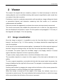
Download - D

Transcript
Viewer
Rev. 3.0 - 2012
D-Sight Viewer
Table of contents
VIEWER...............................................................................................................................1 TABLE OF CONTENTS ...................................................................................................... 2 1 GENERAL DESCRIPTION ........................................................................................... 4 1.1 Opening a file JPeg2000 ......................................................................................... 4 1.2 Opening a case exported from D-Sight ................................................................. 6 1.3 Closure of an open file ........................................................................................... 7 2 VIEWER .......................................................................................................................8 2.1 Image visualization ................................................................................................. 8 2.2 Browser .................................................................................................................... 9 2.3 Measurements ....................................................................................................... 10 2.3.1 Measuring a linear distance ............................................................................. 11 2.3.2 Measuring the area and perimeter of rectangles.............................................. 11 2.3.3 Measuring the circumference and area of an ellipse........................................ 12 2.3.4 Measuring the distance of a point from a straight line ...................................... 12 2.3.5 Measuring angles ............................................................................................. 12 2.3.6 Measuring the perimeter of any open figure .................................................... 12 2.3.7 Measuring the perimeter and area of any closed figure ................................... 13 2.3.8 Measuring a polygon distance ......................................................................... 13 2.3.9 Measuring the area of a polygon...................................................................... 13 2.4 Drawings ................................................................................................................ 14 2.4.1 The elements of a drawing ............................................................................... 15 2.5 Bookmarks ............................................................................................................ 16 2.6 Analysis: ................................................................................................................ 17 2
D-Sight Viewer
2.7 Validation: .............................................................................................................. 18 2.8 Full screen: ............................................................................................................ 19 2.9 Save: ...................................................................................................................... 19 2.10 Photo: ..................................................................................................................... 19 2.11 Lens: ...................................................................................................................... 20 2.12 Color adjustements: ............................................................................................. 21 2.13 View Preview: ........................................................................................................ 21 2.14 Edit visible: ............................................................................................................ 21 2.15 View Label: ............................................................................................................ 22 2.16 Start/Stop film recording: ..................................................................................... 22 2.17 User: ....................................................................................................................... 22 2.18 Z-Stack: .................................................................................................................. 23 2.19 Analysis tools ........................................................................................................ 24 3 REMOTE DIGITAL MICROSCOPE............................................................................ 25 3
D-Sight Viewer
1 General Description
D-Sight Viewer is a software that allows the visualization, browser and interaction with a
digital slide, produced and exported by the D- Sight system.
Fig. 1-1: D-Sight Viewer Icon
Double clicking on the D-Sight Viewer icon (Fig. 1-1) on the desktop, the program get
started,and the main window is shown (Fig. 1-2). To enter the visualization it is enough to
select a file JPeg2000 (file with extention ‘jp2’) or an exported case from D-Sight (file with
extention ‘gxp’).
1.1
Opening a file JPeg2000
In the window of file opening, select ‘File jp2 (*.jp2)’ in the file type combobox. Select the
file you wish to open, and press the button ‘Open’.
4
D-Sight Viewer
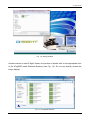
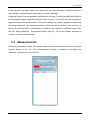
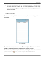
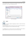
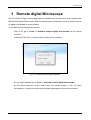
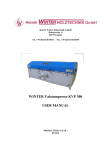
Fig. 1-2: starting window
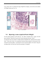
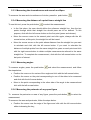
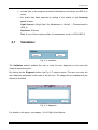
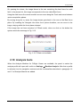
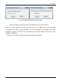
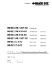
Another chance to start D-Sight Viewer is to perform a double click on the appropriate icon
of file JPeg2000 inside Windows Explorer (see Fig. 1-3). So, we can directly access the
image display.
Fig. 1-3: JPeg2000 selection
5
D-Sight Viewer
In any case, once it is chosen the image JPeg2000 to display, we enter the main window
of D-Sight Viewer (see Fig. 1-4).
Fig. 1-4: main window
1.2
Opening a case exported from D-Sight
On the entering window of a file (see Fig. 1-2), select “complete case“‘ (*.gxp)’ in the file
type combobox. Select the file you wish to open and press the button “Open”.
An exported case may consist of multiple browser JPeg2000 files, acquired from the same
slide. If the case is open, it is composed of several acquired regions, at the top left of the
window the preview gallery is presented for all the acquired regions of the slide. Using the
scrolling arrows, the user can view all the previews in the gallery.
6
D-Sight Viewer
Fig. 1-5: gallery
We must click on a region with the left button of the mouse in order to visualize it. If there
is only one region, it will be open automatically.
In any case, when a region is displayed and navigable, the visualization window will be the
one shown in Fig. 1-4.
1.3
Closure of an open file
To open a new JPEG2000 image click on File Æ Open Jp2.
The viewing of current image will be interrupted
To close the program click on “x” button on top-right corner of window or click on File Æ
Exit.
7
D-Sight Viewer
2 Viewer
The areas of the digital slide are viewed by means of a virtual microscope in which the
viewing objective can be modified (including with dynamic magnification) and moved from
one region of the slide to another.
Furthermore, tools for coordinate memorisation with annotations, image editing tools (texts
or geometrical figures) and interactive measuring tools that enable us to memorise
measurements are available.
Each tool provides the opportunity to relocate the various points previously memorised.
The viewer environment also enables the authorised user to enter his own diagnosis on
the case displayed and produce a report. On this question see paragraph 2.7 for entry of
the diagnosis and chapter 11 for the reporting.
2.1
Image visualization
Once the image is opened, it is possible to enter the form that allow to visualize and
browse it, as shown in Fig. 1-4. At the opening, it is always selected the magnifying level
used for acquisition.
At the top left of the window the preview gallery is presented for all the acquired regions of
the slide. Using the scrolling arrows, the user can view all the previews in the gallery.
In automatic, the system opens the scrollable image in the display window. If several
regions have been acquired, the first is opened by default.
To open another, simply double click on it with the left button of the mouse.
The acquisition objective is unique for all the regions of the slide and is indicated in the
gallery.
To view a region's acquisition, just double left click with the mouse inside its preview: the
image is displayed on the right half of the screen The navigator is simultaneously enabled,
beneath the gallery.
Scrolling can be done by dragging the image with the left button of the mouse pressed for
short movements, or with the navigator for longer movements.
When the mouse is moved up to the edges of the image, the indicator turns into a
horizontal or vertical arrow The arrow indicates the browsing direction in which the image
will be moved when the left button of the mouse is pressed.
8
D-Sight Viewer
By rolling the mouse wheel forward or backwards we can continually increase or decrease
the magnification of the image displayed.
By double clicking on the image we automatically move it from that point to the centre of
the displayed region. This operation is very useful when we want to display a detail of the
image at various magnifications. Indeed, the detail will always be in the central part of the
displayed region and it won't be necessary to execute any movements in order to be able
to see it when varying the zoom levels.
It is also possible to navigate through the image using the directional keys (arrows).
In the displayed image we can carry out measurements, make drawings and memorise the
positions of areas of particular interest.
2.2
Browser
At the time of opening an image the panel Browser appears (see Fig. 2-1).
At the top of the panel there are some summary data of acquisition: the identifying of the
region, the objective of acquisition, the image dimension, the position and the current
levels of magnification. On the right side there are some buttons that allow to select the
objective for image visualization. When opening the image, the objective used for
acquisition is selected automatically.
Fig. 2-1: Browser
Pressing the button Fit the system automatically set up the zoom level needed to contain
the whole image on the screen, considering the resolution of the monitor.
9
D-Sight Viewer
At the centre of the panel there is the preview of the acquired region. Inside it is shown a
red rectangle, representing the acquisition currently displayed.
Using the browser are two possible techniques for moving: The first provides the shifting of
the rectangular region using the left button of the mouse, it is useful if we want to explore a
region moving continuously inside it. During the shifting, the system upgrades continuously
the image displayed. The second provides to click with the left button of the mouse in a
point of the preview, and it is used when we want to move quickly in a different region from
the one being displayed. The Browser button (see Fig. 1-4) on the toolbar, consents to
visualize or not the browser itself.
2.3 Measurements
Distances, perimeters, areas, etc. can be measured with interactive controls by using the
window shown in Fig. 2-2. The measurement function is enabled by pressing the
“Measure” push-button in the tool bar.
Fig. 2-2: Interactive measurements
10
D-Sight Viewer
The measurements taken are automatically saved and overprinted on the image, and will
be visible at all the magnifications and available for subsequent searches.
For each measurement performed, the user can set the color, stroke thickness, font size
and type by using the controls shown in Fig. 2-2.
Before taking a measurement, select the specific push-button for the kind of measurement.
Already performed measurements are listed in a specific list where each line contains a
measurement and (from left to right) the type, value and a brief description, if applicable,
added by the user for better identification.
To enter or edit the description of a measurement, just click with the right mouse button on
the specific item identifying that measurement in the list and select the menu item
“Description…”: a window will be opened where the user can type or edit the text.
When a measurement is selected from the list (by double clicking with the left mouse
button), the viewer will be automatically updated and show the region where the
measurement has been taken.
To eliminate a measurement from the list, select it with the left mouse button and press
to confirm the elimination. To eliminate all the measurements from the list, press
without selecting any item.
If the “move” check button is selected the user can freely position the measurement value.
2.3.1 Measuring a linear distance
To measure a linear distance, press the push-button
to select the measurement and
proceed as follows:
• Click with the left mouse button on the starting point of the distance to be measured;
• Holding the button down, move the cursor to the other end of the distance;
• Release the mouse button.
2.3.2 Measuring the area and perimeter of rectangles
To measure the area and perimeter of rectangles, press the push-button
to select the
measurement and follow the steps below:
• Move on one of the apexes of the rectangle and click with the left mouse button
without releasing the key;
• With the key held down, move towards the opposite apex and then release the left
mouse button.
11
D-Sight Viewer
2.3.3 Measuring the circumference and area of an ellipse
To measure the area and circumference of circles, press the push-button
2.3.4 Measuring the distance of a point from a straight line
To use this tool, press the push-button
to select the measurement.
• In the first place, the user should define the reference straight line, then the two
points through which that straight line should pass are to be defined. To this
purpose, click with the left mouse button on the first point (press and release).
• Move the mouse cursor to the second point and click again, always with the left
mouse button; at this point, the straight line will be traced.
• Move the mouse cursor on the point whose distance from the straight line you want
to calculate and click with the left mouse button. If you want to calculate the
distance of multiple points from the same straight line, pass on each point and click
with the right mouse button to obtain multiple measurements referred to the same
straight line. To complete the measurement, click with the left mouse button on the
last point of interest.
2.3.5 Measuring angles
To measure angles, press the push-button
and select the measurement, and follow
the steps below:
• Position the cursor on the vertex of the angle and click with the left mouse button;
• Position the cursor on the point corresponding to one of the sides to be measured
and click with the left mouse button;
• Move to the point corresponding to the other side of the angle to be measured and
click with the left mouse button.
2.3.6 Measuring the perimeter of any open figure
To measure the perimeter or area of any figure, press the push-button
to select the
measurement.
To measure the area and perimeter, follow the steps below:
• Position the cursor near the edge of the figure and click with the left mouse button
without releasing the key;
12
D-Sight Viewer
• Run, with the mouse cursor, all along the perimeter of the figure while holding the
left button down;
• When you have traced all the perimeter of the figure (including the line connecting
the last point to the first), release the left mouse button.
2.3.7 Measuring the perimeter and area of any closed figure
To measure the perimeter or area, press the push-button
to select the measurement.
To measure the area and perimeter, follow the steps below:
• Position the cursor near the edge of the figure and click with the left mouse button
without releasing the key;
• Run, with the mouse cursor, all along the perimeter of the figure while holding the
left button down;
• When you have traced all the perimeter (including the line connecting the last point
to the first), release the left mouse button.
2.3.8 Measuring a polygon distance
To measure several linear distance in a sequence or the perimeter of a polygon, use this
method. Press the push-button
and follow the steps below:
• Click on the starting point;
• Position the mouse cursor on the point of interest;
• Click again with the left mouse button;
• Repeat the previous steps for as many measurements as required;
• Finally, position the cursor on the last point and double click, still with the left mouse
button.
2.3.9 Measuring the area of a polygon
To measure the area of a polygon, press the push-button
and follow the steps below:
• Position the cursor on the first vertex of the polygon and click with the left mouse
button;
• Move on the subsequent vertexes and click again with the left mouse button;
• When you reach the last vertex, double click on it with the left mouse button.
13
D-Sight Viewer
2.4 Drawings
The “Drawings” push-button in the tool bar enables the «Overlay drawing...» push-button
(Fig. 2-3). If the viewer has been set in the full-screen mode, press the F2 function key to
activate the operation.
The drawings created by the user are automatically saved as an image overlay and will be
available for viewing at all magnifications for subsequent browsing.
For each drawing created, the user can set the color, stroke thickness, font type and size
by using the control keys shown in Fig. 2-3.
Before creating a drawing, select the specific type of drawing you want to create with the
corresponding push-button in the “Drawing Elements” box.
Already created drawings are shown in a specific list: each line represents a drawing and
contains the type of drawing created and a short description added by the user for better
identification.
To add or change the description of a drawing, just click with the right mouse button on the
specific element in the related list and select the menu item “Description…”. A window will
be opened where the user can type or edit text.
Select a drawing from the list (by double clicking on it with the left mouse button) and the
viewer will be automatically updated to show the region where the drawing was created.
To eliminate a drawing from the list, select it by clicking on it with the left mouse button and
to confirm the operation. To eliminate all drawings from the list,
press the push-button
.
Select the option “Fill the figure” and the drawn region will be filled with the current color.
14
D-Sight Viewer
Fig. 2-3: Overlay drawing
2.4.1 The elements of a drawing
The types of drawing available are:
• Straight line: press the left mouse button (and hold it down) and move the cursor
until you have reached the target point, then release the left mouse button.
• Arrow: follow the steps described for the drawing of a straight line. The tip of the
arrow should be positioned in the mouse release point.
• Rectangle: press the left mouse button (and hold it down), trace the size and shape
desired and then release to validate.
• Ellipse: follow the steps described for the creation of a rectangle.
• Open/Closed freehand line: to draw any line with a free hand, follow she same
steps described to trace a straight line.
• Open/Closed polygonal line: click with the left mouse button to start the drawing;
move and click again with the left mouse button to define the polygon vertexes;
double click with the left mouse button to complete the drawing.
15
D-Sight Viewer
• Text: when the user selects the “Text” push-button, a window is displayed where
text can be typed. After pressing “OK”, the written text is hooked on by the mouse
cursor and can be dragged into the target position. Click in the target position to fix
the text in the image.
2.5 Bookmarks
To store some focus points in the system memory, the user can simply add some
“Bookmarks”.
Fig. 2-4: Bookmark
The bookmark management window (see Errore. L'origine riferimento non è stata
trovata.) is enabled by pressing the Bookmark button under the navigator.
To memorise the position of a point of interest, just bring the viewer into the desired
position and press the
button, on which the point will be added to the list.
16
D-Sight Viewer
By selecting a point of interest from the list (double left click with the mouse) the navigator
automatically updates, showing the region of the image that contains the point.
To delete a point of interest from the list, it must be selected by left clicking it with the
mouse and pressing the
from the list, press the
button to confirm the operation. To eliminate all drawings
button.
Once the position of a point of interest has been memorised, we can right click with the
mouse on the corresponding row in the Errore. L'origine riferimento non è stata
trovata. panel in order to:
•
Enter a description;
•
Associate an image. The Fig. 2-5 panel opens, which enables us to
associate images in Jpeg, Bitmap and Tiff format to the point.
For each associated image, we can carry out the following operations:
• Remove it;
• Enter a description;
• Display it;
Fig. 2-5: File association
2.6
Analysis:
The last section of the panel, the Analyses one, in the standard viewer is disabled. This is
active provided:
17
D-Sight Viewer
•
at least one of the analyses modules (Membranes and Nuclei or HER-2) is
active
•
the screen has been acquired by setting in the wizard, in the Scanning
panel window:
Light SourceÆ Bright field (for Membranes e Nuclei) – Fluorescence(for
HER-2)
Specimen Æ Breast
Test Æ one of the analysis profiles (of membranes, nuclei or FISH HER-2)
2.7
Validation:
Fig. 2-6: validation
The Validation section enables the user to enter his own diagnosis on the case and
create a report document.
By clicking on the Diagnosis button, the Fig. 2-7 window opens. The user can enter his
own diagnosis associated to the case in the text box. The diagnosis can subsequently be
deleted or modified.
Fig. 2-7: diagnosis
For details on the report, see chapter 11 of D-Sight User Manual.
18
D-Sight Viewer
2.8
Full screen:
Enables us to view the image at full screen. The navigator remains visible and
so does the toolbar on the right of the screen.
To exit full screen mode and return to the viewer, just click on the button again.
2.9
Save:
Saves the scanned region. In the dialogue window (see Fig. 2-8) that appears
the user can choose the destination folder and the name to be assigned to the file.
Fig. 2-8: saving jp2
2.10
Photo:
During navigation of a scan, photos showing details of particular interest can be
saved. To do this, simply display the detail of interest at the desired magnification and
press the Photo button in the toolbar at the right of the screen. The system automatically
19
D-Sight Viewer
opens the dialogue window, in which the user can choose the destination folder in which to
save the photo in *.bmp, *.jpeg, *.tif formats (see Fig. 2-9).
Fig. 2-9: saving photo
2.11
Lens:
The Lens button renders the magnifying lens visible or invisible at the bottom
left of the image viewer.
This window shows the content of the region of the viewer in which the mouse pointer is
located; the magnifying lens' zoom level is double that of the image.
The magnifying lens is very useful if we want to see a particular part of the screen in
greater detail without having to increase the zoom level of the entire image.
20
D-Sight Viewer
2.12
Color adjustements:
opens the Fig. 2-10 panel, in which we can adjust various parameters of the
image (brightness, contrast, gamma, etc...)
Fig. 2-10: adjustment of the image
2.13
View Preview:
opens a window in which the preview of the entire slide is visible.
2.14
Edit visible:
renders visible or invisible any editing done by the user with the Measurements
and Drawings tools.
21
D-Sight Viewer
2.15
View Label:
if the case has been acquired with Barcode Reading mode (see paragraph 6.2.3
of D-Sight User Manual) we can use this command to display the slide's label. If the case
has not been acquired with this mode, the button is not enabled.
2.16
Start/Stop film recording:
this command starts and stops the recording of a film. Indeed, the system allows
the user to film the operations he is carrying out.
2.17
User:
this command enables the authorised user to display certain operations carried
out on the case by other users from the same group or by all other users of the system,
depending on the permits granted by the administrator.
More specifically, subject to his own permits, the user can display the films, analyses and
image editing carried out by other users on the case in question.
Clicking on the button opens a drop-down menu from which we can select the operation
we wish to display.
The window that opens contains two tables: the one on the left details the list of users who
have carried out the operations selected and the one on the right the list of all the
operations that meet the search criteria.
1. VIDEO
If we select a film-related element in the table, a new list opens listing all films made by the
selected user. If we right click with the mouse on the element in question, the pop-up
menu appears in which we can:
•
Start reproducing of the video;
•
Delete the video if it belongs to the user currently logged in.
22
D-Sight Viewer
If the user does not have the permits to display other users' operations he can however
review and possibly eliminate his own videos by accessing the User panel. In this case he
will only be able to select his own name from the Users combo box.
2. ANALYSIS
If we select an analysis-related element in the table, a pop-up menu appears in which we
can:
•
Display the analyses drawn up on the case by the selected user;
•
Acquire as our own the analysis made by the selected user.
3. EDITING THE IMAGE
If we select an editing-related element in the table, a pop-up menu appears in which we
can:
•
2.18
Display the measurements, drawings or zones of interest (bookmark) made
by the selected user.
Z-Stack:
if the slide being displayed has been acquired in Z-Stack mode (see paragraph
6.4.2 of D-Sight User Manual), clicking on the button opens the panel in Fig. 2-11.
Fig. 2-11: Z-Stack Management
23
D-Sight Viewer
On opening the viewer, the image shown is the one containing the best focus for each
field. In the planes list, this image corresponds to the one called Best focus.
Using the slide bar or the mouse scroller we can move along the Z axis and move between
various acquisition planes.
By moving along the x-y axes, the image shown goes back to the one on the Best focus
plane. By enabling the Navigate the active focus plane checkbox, we can move in the
image, staying within the focus plane selected.
If the image has not been acquired in Z-Stack mode, when we click on the button the
system sends the message in Fig. 2-12.
Fig. 2-12: Z-Stack not available
2.19 Analysis tools
When the Analysis Modules for D-Sight Viewer are available, the panel to select the
analysis profile will open with aclick on Settings Æ Enables Analysis. After that a profile
is selected, into the navigation environment the functionalities described in paragraph 1.2
and 1.3 of Analysis Manual are added.
24
D-Sight Viewer
3 Remote digital Microscope
The PC where D-Sight Viewer application is installed can be used as a client system with
the Remote Digital Microscope. With this functionality is possible to have a remote control
of digital microscope of server system.
To access this functionality we need to:
‐
First of all, go to Tools Æ Activate remote digital microscope on the server
machine.
At this point the Fig. 3-1 panel opens on the server machine.
Fig. 3-1: creating an access password
‐
On the client machine go to Tools Æ Activate remote digital microscope.
‐
On the client machine, on the other hand, the panels shown in Fig. 3-2 open
successively, in which we must enter the data generated on the server machine.
25
D-Sight Viewer
Fig. 3-2: entering customer machine data
‐
Enter the Computer name and then the Password in the client machine.
Once we have entered the data, we must click on the OK button and the digital
microscope will start on both machines. This environment's functionalities are those
detailed in chapter 10 and can be used both by the server machine and by the client
machine, alternately.
To close the connection, simply exit the microscope environment.
26