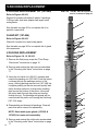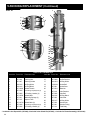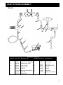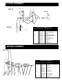
1
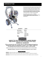
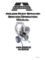
AIRLESS PAINT SPRAYER
SERVICE/OPERATION
MANUAL
AIRLESSCO
SL6250
001-809 APR08
1
TABLE OF CONTENTS
Product Diagrams & Parts Lists
Introduction
Description & Specifications................................. 1 Fluid Pump ...................…...................................
Safety Warnings .................................................. 2 Paint System ................................………...........
Manifold Filter Assembly .......……...…...............
Electrical Control Board .....................................
Getting Started
Setting Up........................................................... 5 Prime Valve ........................................................
Flushing............................................................... 6 Clutch Replacement .............................................
How to Flush ....................................................... 7 Clutch Assembly ...................................................
Starting Flush ....................................................... 8 Engine Assembly ..................................................
Pressure Relief Procedure ................................ 10
Power Unit ..............…………………………….....
Frame Assembly ..................................................
Repair/Maintenance Instructions
Spray Gun Operation ............................................ 11 Suction Assembly .................................................
Spray Gun Troubleshooting ................................ 12 Accessories ..........................................................
Spray Tip Selection .. .......................................... 13
Regular Maintenance .......................................... 14
Oil & Lubrication Instructions ..............………….. 14
Field Troubleshooting ........................................... 15
Servicing the Fluid Pump .................................... 16
Servicing the Inlet & Outlet Valves ...................... 17
Packing Replacement .….................................... 18
Electrical Troubleshooting-Clutch Doesn't Engage 23
Replacement of Electrical Control Board ............ 24
Calibration of Electrical Control Board ................. 24
Clutch Replacement ............................................. 25
2
20
21
23
24
28
26
27
27
28
29
29
30
INTRODUCTION
This gas powered airless sprayer is built tough to take
the day after day high volume demands of painting
contractors and equipment rental companies. The SL
"Slow Stroker" paint pump features a large, severe
duty, slow-stroking stainless steel piston. Airlessco's
patented stationary triple-life packing system allows
external adjusment of upper & lower packings.
This SL6250 airless pumps are "Built to
Perform...Built to Last" using the latest technology
in pump design for smooth operation and low
maintenance.
AIRLESSCO
Max. Pressure
Output (FreeFlow)
Output (At Pressure)
Tip Size
Motor
Weight
SL6250
3000 psi
0.0 gpm
1.7 gpm
1 gun to 0.041"
2 gun to 0.029
Honda GX160
136 lbs
HANDLE THIS UNIT AS YOU WOULD A LOADED FIREARM!
High pressure spray can cause extremely serious injury.
OBSERVE ALL WARNINGS!
Before operating this unit, read and follow all safety warnings and instructions
related to the usage of this equipment on pages 2, 3 & 4. READ, LEARN, and
FOLLOW the Pressure Relief Procedure on Page 10 of this manual.
All Service Procedures to be performed by an Authorized Airlessco Service Center ONLY.
NO MODIFICATIONS or alterations of any AIRLESSCO Equipment or part is allowed.
MANUAL NOTATIONS
WARNING - Alerts user to avoid or correct conditions that could cause bodily injury.
CAUTION - Alerts user to avoid or correct conditions that could cause damage to or destruction of equipment.
IMPORTANT - Alerts users to steps or procedures that are essential to proper equipment repair and maintenance.
1
WARNINGS
MEDICAL ALERT - Airless Spray
Wounds
If any fluid appears to penetrate your skin, get
EMERGENCY MEDICAL CARE AT ONCE. DO
NOT TREAT AS A SIMPLE CUT. Tell the doctor
exactly what fluid was injected. Have him read
NOTE TO PHYSICIAN: Injection in the skin is
a traumatic injury. It is important to treat the injury
surgically as soon as possible. DO NOT DELAY
treatment to research toxicity. Toxicity is a concern
with some exotic coatings injected directly into the
blood stream. Consultation with a plastic surgeon or
reconstructive hand surgeon may be advisable.
HIGH PRESSURE SPRAY CAN CAUSE EXTREMELY SERIOUS INJURY.
OBSERVE ALL WARNINGS. THIS SPRAYER FOR PROFESSIONAL USE ONLY.
INJECTION HAZARD
ALWAYS INSPECT SPRAYING AREA
Fluids under high pressure from spray or leaks can
penetrate the skin and cause extremely serious injury,
including the need for amputation.
NEVER point the spray gun at anyone or any part of the
body.
NEVER put hand or fingers over the spray tip. Do not use
rag or other materials over your fingers. Paint will penetrate
through material and into the hand.
NEVER try to stop or deflect leaks with your hand or body.
ALWAYS have gun tip guard in place when spraying.
ALWAYS lock gun trigger when you stop spraying.
ALWAYS remove tip from the gun to clean it.
NEVER try to "blow back" paint, this is not an air spray
sprayer.
ALWAYS follow the PRESSURE RELIEF PROCEDURE, as
shown on page 8, before cleaning or removing the spray tip
or servicing any system equipment.
Be sure equipment safety devices are operating properly
before each use.
Tighten all fluid connections before each use.
Keep spraying area free from obstructions.
Make sure area has good ventilation to safely remove
vapors and mists.
NEVER keep flammable material in spraying area.
NEVER spray in vicinity of open flame or other sources of
ignition.
Spraying area must be at least 20 ft. away from spray unit.
MEDICAL TREATMENT
ALWAYS set safety lock on the gun in "LOCKED" position
when not in use and before servicing or cleaning.
DO NOT remove or modify any part of gun.
ALWAYS REMOVE SPRAY TIP when cleaning. Flush unit
with LOWEST POSSIBLE PRESSURE.
CHECK operation of all gun safety devices before each
use.
Be very careful when removing the spray tip or hose from gun.
A plugged line contains fluid under pressure. If the tip or line
is plugged, follow the PRESSURE RELIEF PROCEDURE
as outlined on page 6.
If any fluid appears to penetrate your skin, get EMERGENCY
CARE AT ONCE. DO NOT TREAT AS A SIMPLE CUT.
TIP GUARD
* Go to an emergency room immediately.
* Tell the doctor you suspect an injection injury.
* Tell him what kind of material you were spraying with and
have him read NOTE TO PHYSICIAN on pg. 6.
GENERAL PRECAUTIONS
NEVER alter equipment in any manner.
NEVER smoke while in spraying area.
NEVER spray highly flammable materials.
NEVER use around children.
NEVER allow another person to use sprayer unless he is
thoroughly instructed on its' safe use and given this operators manual to read.
ALWAYS wear a spray mask, gloves and protective eye
wear while spraying.
ALWAYS ensure fire extinquishing equipment is readily
available and properly maintained.
NEVER LEAVE SPRAYER UNATTENDED WITH
PRESSURE IN THE SYSTEM. FOLLOW PRESSURE
RELIEF PROCEDURES ON PAGE 6.
2
SPRAY GUN SAFETY
ALWAYS have the tip guard in place on the spray gun while
spraying. The tip guard alerts you to the injection hazard and
helps prevent accidentally placing your fingers or any part of
your body close to the spray tip.
SPRAY TIP SAFETY
Use extreme caution when cleaning or changing spray tips.
If the spray tip clogs while spraying, engage the gun safety
latch immediately. ALWAYS follow the PRESSURE RELIEF
PROCEDURE before removing the spray tip to clean it.
NEVER wipe off build up around the spray tip.
ALWAYS remove tip & tip guard to clean AFTER
pump is turned off and the pressure is relieved by following
the PRESSURE RELIEF PROCEDURE.
WARNINGS CONTINUED ON NEXT PAGE.............
WARNINGS - Continued
KEEP CLEAR OF MOVING PARTS
TOXIC FLUID HAZARD
Keep clear of moving parts when starting or operating the
sprayer. Do not put your fingers into any openings to avoid
amputation by moving parts or burns on hot parts.
Precaution is the best insurance against an accident.
Hazardous fluid or toxic fumes can cause serious injury or
death if splashed in eyes or on skin, inhaled or swallowed.
Know the hazards of the fluid you are using. Store & dispose
of hazardous fluids according to manufacturer, local, state &
national guidelines.
When starting the engine, maintain a safe distance from moving
parts of the equipment.
ALWAYS wear protective eyewear, gloves, clothing
and respirator as recommended by fluid manufacturer.
Before adjusting or servicing any mechanical part of the
sprayer, follow the PRESSURE RELIEF PROCEDURE on
page 6, and remove the ignition cable from the spark plug to
prevent accidental starting of sprayer.
GROUNDING
Ground the sprayer and other components in the system
to reduce the risk of static sparking, fire or explosion
which can result in serious bodily injury and property
damage.
HOSES
Tighten all fluid connections securely before each use.
High pressure fluid can dislodge a loose coupling or allow
high pressure spray to be emitted from the coupling and
result in an injection injury or serious bodily injury.
Use only hose that has a spring guard. The spring guard
helps protect the hose from kinks or other damage which
could result in hose rupture and cause an injection injury.
NEVER use a damaged hose, which can result in hose
failure or rupture and cause in injection injury or other
serious bodily injury or bodily damage. Before each use,
check entire hose for cuts, leaks, abrasion or bulging of
cover, or damage or movement of couplings. If any of
these conditions exist, replace the hose immediately.
Never use tape or any device to try to mend the hose
as it cannot contain the high pressure fluid. NEVER ATTEMPT TO RECOUPLE THE HOSE. High pressure hose
is not recoupleable.
Always ground all of these components:
1. Sprayer: Connect a ground wire and clamp (supplied)
to a true earth ground.
2. Fluid Hose: use only grounded hoses.
3. Spray gun or dispensing valve: grounding is obtained
through connection to a properly grounded fluid hose
and pump.
4. Object being sprayed: according to your local code.
5. All solvent pails used when flushing should only be
metal pails which are conductive.
Once each week, check electrical resistance of hose
(when using multiple hose assemblies, check overall
resistance of unpressurized hose must not exceed 29
megohms (max) for any coupled length or combination
of hose lengths. If hose exceeds these limits, replace it
immediately.
Never exceed 500 Ft. (150 m.) overall combined hose
length to assure electrical continuity.
Help prevent damage to the hose by handling and routing carefully. Do not move the sprayer by pulling it with
the hose.
LABELING
Keep all labels on the unit clean and readable. Replacement labels are available from manufacturer.
WARNINGS CONTINUED ON NEXT PAGE.............
3
WARNINGS - Continued
AVOID COMPONENT RUPTURE
PREVENT STATIC SPARKED FIRE/ EXPLOSIONS
This sprayer operates at 3000 psi (205 bar). Always
be sure that all components and accessories have a
maximum working pressure of at least 3000 psi to avoid
rupture which can result in serious bodily injury including
injection and property damage.
ALWAYS be sure all equipment and objects being sprayed
are properly grounded. Always ground sprayer, paint bucket
and object being sprayed. See "grounding" on page 8 for
detailed grounding information.
NEVER leave a pressurized sprayer unattended to avoid
accidental operation of it which could result in serious
bodily injury.
ALWAYS follow the PRESSURE RELIEF PROCEDURE
whenever you stop spraying and before adjusting, removing or repairing any part of the sprayer.
NEVER alter or modify any part of the equipment to avoid
possible component rupture which could result in serious
bodily injury and property damage.
NEVER use weak or damaged or non-conductive paint
hose. Do not allow kinking or crushing of hoses or allow it
to vibrate against rough or sharp or hot surfaces. Before
each use, check hoses for damage and wear and ensure
all fluid connections are secure.
REPLACE any damaged hose. NEVER use tape or any
device to mend the hose.
NEVER attempt to stop any leakage in the line or fittings
with your hand or any part of the body. Turn off the unit
and release pressure by following PRESSURE RELIEF
PROCEDURE.
ALWAYS use approved high pressure fittings and replacement parts.
ALWAYS ensure fire extinquishing equipment is readily
available and properly maintained.
WARNING
Do not use halogenated solvents in this system.
The prime valve, 2 gun manifold and most airless
guns have aluminum parts and may explode.
Cleaning agents, coatings, paints or adhesives
may contain halogenated hydrocarbon solvents.
DON"T TAKE CHANCES! Consult your material
suppliers to be sure. Some of the most common
of these solvents are: Carbontetrachloride, Chlorobenzene, Dichloroethane, Dichloroethyl Ether,
Ethylbromide, Ethylchloride, Tethrachloethane.
Alternate valves and guns are available if you
need to use these solvents.
Vapors created when spraying can be ignited by sparks.
To reduce the risk of fire, always locate the sprayer at least
20 feet (6 m.) away from the spray area. Do not plug in or
unplug any electrical cords in the spray area, which can
create sparks, when there is any chance of igniting vapors
still in the air. Follow the coating & solvent manufacturers
safety warnings and precautions.
Use only conductive fluid hoses for airless applications. Be
sure gun is grounded through hose connections. Check
ground continuity in hose & equipment. Overall (end to
end) resistance of unpressurized hose must not exceed 29
megohms for any coupled length or combination of hose
length. Use only high pressure airless hoses with static wire
approved for 3000 psi.
FLUSHING
Reduce the risk of injection injury, static sparking or
splashing by following the specific cleaning procedure
on page 4 and 9.
ALWAYS follow the PRESSURE RELIEF PROCEDURE
on page 8.
ALWAYS remove the spray tip before flushing. Hold a
metal part of the gun firmly to the side of a metal pail and
use the lowest possible fluid pressure during flushing.
NEVER use cleaning solvents with flash points below 140
degress F. Some of these are: acetone, benzene, ether,
gasoline, naphtha. Consult your supplier to be sure.
GAS ENGINE PRECAUTIONS
Locate unit 25 feet away from spray area in well ventilated area. NEVER operate in closed building unless
exhaust is piped outside. NEVER allow hose to lay
against engine mufflers or hot parts. NEVER refill
fuel tank while engine is hot or is running.
Important: United States Government safety standards
have been adopted under the Occupational Safety &
Health Act. These standards, particularly the General
Standards, Part 1910, & the Construction Standards,
part 1926 should be consulted.
WHEN SPRAYING & CLEANING WITH FLAMMABLE PAINTS OR THINNERS:
1. When spraying with flammable liquids, the unit must be located a minimum of 25 feet away from the spraying
area in a well ventilated area. Ventilation must be sufficient enough to prevent the accumulation of vapors.
2. To eliminate electrostatic discharge, ground the spray unit, paint bucket and spraying object. Use only high
pressure airless hoses approved for 3000 psi which is conductive.
3. Remove spray tip before cleaning gun and hose. Make contact of gun with bucket and spray without the tip in
a well ventilated area, into the grounded steel bucket.
4. Never use high pressure in the cleaning process. USE MINIMUM PRESSURE.
5. Do not smoke in spraying/cleaning area.
4
SETTING UP
1. Connect the hose and gun
a. Remove the plastic cap plug from the outlet and
screw a conductive or grounded 3000 psi
spray hose onto fluid outlet.
b. Connect an airless spray gun to the other end of the
hose, but do not install the spray tip yet!
NOTE: Do not use thread sealer on swivel unions as they
are made to self seal.
NOTE: The first 50' of hose should always be 3/8".
2. Fill the Packing Nut/Wet Cup
Fill the Packing Nut/Wet Cup 1/3 full with Airlessco
Throat Seal Oil (TSO). Fig 1 below.
FIG. 1
3. Check the Engine Oil Level
a. Unscrew the oil fill plug. The dipstick is attached to
the plug.
b. Without threading the plug into place, check to be
sure the oil is up to the top mark on the dipstick.
c. If oil is needed, refer to engine manual.
4. Fill the Fuel Tank
WARNING: Fuel spilled on a hot surface can
cause a fire or explosion and cause serious
bodily injury and property damage. Always
shut off the engine and let it cool before filling the tank, and carefully follow steps a - c
below being sure not to spill any fuel.
a. Close the fuel shutoff valve.
b. Use only clean, fresh, well-known brands of
unleaded regular grade gasoline.
c. Remove the fuel cap and fill tank. Be sure the air
vent in the fill cap is not plugged so fuel can flow to
the carburetor, then replace the cap.
5
FLUSHING - Read Prior to Using Your Sprayer
1. New sprayer
Your unit was factory tested in an anti-freeze
solution which was left in the pump. Before
using oil-base paint, flush with mineral spirits only.
Before using water-base paint flush with
mineral spirits, followed by soapy water, then
a clean water flush.
2. Changing colors
Flush with a compatible solvent such as
mineral spirits or water.
3. Changing from water-base to oil-base paint.
Flush with soapy water, then mineral spirits.
4. Changing from oil-base to water-base paint.
Flush with mineral spirits, followed by soapy
water, then a clean water flush.
6
5. Storage
Oil-base paint: Flush with mineral spirits.
Water-base paint: Flush with water, then mineral
spirits and leave the pump, hose and gun filled
with mineral spirits.
For longer storage, use mixture of mineral spirits
and motor oil (half & half). Shut off the sprayer,
follow Pressure Relief Procedure on page 6 to
relieve pressure and make sure prime valve is left
open.
6. Start up after storage
Before using water-base paint, flush with soapy
water and then a clean water flush.
When using oil-base paint, flush out the mineral
spirits with the material to be sprayed.
HOW TO FLUSH
FIG. 2
FIG. 4
REMOVE
SPRAY
TIP
Choke Lever
FIG. 3
PRESSURE CONTROL
KNOB
PRIME VALVE
Open
(Priming &
Pressure Relief)
Closed
(Pressure)
High
Pressure
Low
Pressure
1. Be sure the gun safety latch is engaged and there
is no spray tip in the gun. Refer to Fig. 2. Refer to
your separate instruction manual provided with your
gun on its safety features and how to engage safety
latch.
2. Pour enough clean, compatible solvent into a large,
empty metal pail to fill the pump and hoses.
3. Place the suction tube into the pail or place the pail
under the pump.
4. Turn the pressure control knob to low pressure. Refer
to Fig. 3.
5. Open the prime valve to the open - "Priming Position".
This will allow an easy start. Refer to Fig. 3.
6. Turn the engine ON/OFF switch to ON.
7. Move the choke toward the closed position as per Fig.4.
8. Move the throttle lever slightly to the left as per Fig.4.
9. Turn the fuel valve ON as per Fig. 4. Pull the start rope.
Pull the engine over against compression stroke and
then let the rope rewind slowly into the starter. Pull
firmly and rapidly to start the engine. Do NOT drop the
rope. Hold on to the handle while rewinding, or the rope
may rewind improperly and jam the assembly. If the
engine does not start, open the choke a little more. If
the engine floods, open the choke all the way and continue cranking.
10. After the engine is warm, gradually close the choke
lever, increase the RPM of engine slightly by moving
throttle to the left. Close the prime valve.
Refer to Fig. 3
Fuel Valve
Throttle Lever
FIG. 5
MAINTAIN FIRM
METAL TO METAL
CONTACT BETWEEN
GUN AND CONTAINER
WARNING: To reduce the risk of static sparking,
which can cause fire or explosion, always hold
a metal part of the gun firmly against the metal
pail when flushing. This also reduces splashing.
Refer to Fig 5.
12. Disengage the gun safety latch and squeeze the gun
trigger. At the same time, slowly turn the pressure control knob clockwise just enough to move liquid at low
pressure.
13. Allow the pump to operate until clean solvent comes
from the gun.
14. Release the trigger and engage the gun safety latch.
15. If you are going to start spraying, place the pump or
suction tube into the supply container. Release the
gun safety latch and trigger the gun into another empty,
metal container, holding a metal part of the gun firmly
against the metal pail (Fig. 5), forcing the solvent
from the pump and hose. When paint starts coming
from gun, turn pressure control knob to minimum pressure, place prime valve in prime (open) position and
engage the gun safety latch.
16. If you are going to store the sprayer, remove the suction tube or pump from the solvent pail force the solvent from the pump and hose. Engage the gun safety
latch and refer to the "Storage" Procedure on page 6.
Step 5.
17. Whenever you shut off the sprayer follow the
Pressure Relief Procedure warning on page 10.
11. Point the gun into the metal pail and hold a metal part
of the gun firmly against the pail Refer to fig.5
7
STARTING UP
1. Learn the controls
Pressure Control Knob - used to adjust pressure only.
Turn clockwise to increase pressure and counterclockwise to decrease pressure. (See Fig. 6)
Prime & Pressure Relief Valve - Turn to OPEN position
(see Fig. 7) to prime the pump. Turn to the CLOSED
position to spray.
FOLLOW "PRESSURE RELIEF PROCEDURES"
ON PAGE 6 WHENEVER YOU:
- are instructed to relieve pressure
- stop spraying
- checking or servicing any of the system
equipment.
- or installing or cleaning the spray tip.
Handle spray system as you would a loaded firearm!
CAUTION: Do not start engine without fluid
pump having enough fluid so that it can be
primed. Running fluid pump dry will decrease
life of the pumps packings.
2. Prepare the Material
a. Prepare the material according to the material
manufacturer's recommendations.
b. Place pump or suction tube into material container.
8
FIG. 6
FIG. 7
PRESSURE
CONTROL
KNOB
PRIME VALVE
Open
(Priming &
Pressure Relief)
Closed
(Pressure)
High
Pressure
Low
Pressure
3. Starting the Sprayer (see Fig. 6 & 7 above)
a. Prime Valve must be open - priming position.
b. Pressure Control Knob must be in low pressure.
c. Follow the procedure under "How to Flush", page 7
Steps 6 through 12.
WARNING: To stop the unit in an emergency or
before performing any service or maintenance
procedure follow the Pressure Relief Procedure on page 10 to relieve the fluid pressure.
STARTING UP - continued
4. Prime the Pump
a. Allow pump to operate until paint comes from gun.
b. Release the trigger and engage the gun safety latch.
c. Turn Prime Valve OPEN to the prime position
ensuring the pressure is released from the system.
d. Turn Pressure Control Knob to minimum
pressure.
e. Install spray tip onto gun.
f. Close the prime valve to the pressure position.
g. Turn the pressure control knob to desired spray
pressure.
h. Disengage the gun safety lock and you are ready
to start spraying.
WARNING: If you spray into the paint bucket,
always use the lowest spray pressure and
maintain firm metal to metal contact between
gun and container. See page 7, Fig 5.
5. Adjusting the Pressure
a. Turn the Pressure Control Knob clockwise to
increase pressure and counterclockwise to
decrease pressure.
b. Always use the lowest pressure necessary to
completely atomize the material.
CAUTION - Operating the sprayer at higher
pressure than needed wastes material, causes
early tip wear and shortens sprayer life.
7. Cleaning a Clogged Tip
IMPORTANT WARNING
Always follow the Pressure Relief Procedure on page 8
before perfoming any service or maintenance procedure.
WARNING: Never hold your body, fingers,
or hand in a rag in front of the spray tip when
cleaning or checking it for a cleared tip. Always
point the gun toward the front or into a waste
container when checking to see if the tip is
cleared or when using a self-cleaning tip.
a. Follow the Pressure Relief Procedure on page 10.
b. Clean the front of the tip frequently (with toothbrush
only) during the day to keep material from building up
and clogging the tip.
c. To clean and clear a tip if it clogs, refer to the separate
instruction manual received with your gun and nozzle.
There is an easy way to keep the outside of the tip clean from
material build-up:
Every time you stop spraying, for even a minute, lock the
gun and submerge the gun into a small bucket of thinner
comparable with the material sprayed. Thinner will dissolve
the build up of paint on the outside of tip, tip guard and gun
much more effectively than if the paint dries out completely.
WARNING: Clogged standard flat tip - clean
only after the tip is removed from the gun.
Follow the Pressure Relief Procedure Warning
on Page 10.
8. When Shutting Off the Sprayer
c. If more coverage is needed use a larger tip rather
than increasing the pressure.
d. Check the spray pattern. The tip size and angle
determines the pattern width and flow rate.
6. Reducing Clutch Wear
a. The first 50 feet of airless spray hose should be 3/8",
the larger diameter works as a pulsation damper and
saves unnecessary cycling of the clutch. A minimum
of 100 feet of hose should be used.
b. Adjust the Engine Speed and Pump Pressure.
First set the throttle lever to the maximum RPM
setting (fully left). Trigger the gun onto a test paper
to check the spray pattern and atomization. Adjust
the Pressure Control Knob until you get a good
pattern. Reduce RPM of engine to support pressure
without laboring engines.
a. Whenever stop spraying, even for a short break, follow the Pressure Relief Procedure Warning on page
10.
b. Clean the tip and gun as recommended by your
separate gun instruction manual.
c. Flush the sprayer at the end of each work day if the
material you are spraying is waterbased, or if it could
harden in the sprayer overnight. See "Flushing" page
6. Use a compatible solvent to flush, then fill the pump
and hoses with an oil based sovent such as mineral spirits.
d. For long term shutdown or storage, refer to page 6.
WARNING - Be sure to relieve pressure in the
pump after filling with mineral spirits.
9
Pressure Relief Procedure
PRESSURE RELIEF PROCEDURE
To avoid possible serious bodily injury, including injection, always follow this procedure whenever the
sprayer is shut off, when checking or servicing it, when installing or changing the tips, whenever you stop
spraying or when you are instructed to relieve the pressure.
1. Engage gun safety latch. Refer to
separate instruction manual provided
with your gun on its safety features
and how to engage safety latch.
4. Re-engage gun
safety latch
Open
(Priming &
Pressure Relief)
2. Turn engine off.
3. Disengage safety latch &
trigger gun to relieve residual
fluid pressure. Hold metal part of the gun in contact
with grounded metal pail.
5. Turn Prime/Pressure Relief Valve
as shown open (priming) to
relieve fluid pressure.
Leave prime valve OPEN until you are ready to
spray again.
IF THE SPRAY TIP OR HOSE IS CLOGGED, follow Step 1 through 5 above. Expect paint splashing into the
bucket while relieving pressure during Step 5. If you suspect that pressure hasn't been relieved due to
damaged prime/pressure relief valve or other reason, engage gun safety latch and take your sprayer to an
authorized Airlessco Service Center for service.
10
AIRLESS SPRAY GUN OPERATION
FIG. 8
SPRAY
Attach spray gun to airless unit and tighten fittings securely.
Set the gun safety latch. (Also may be called gun safety lock,
or trigger lock)
* The gun safety latch should always be set when the gun is
not being triggered.
MAJOR COMPONENTS OF SPRAY GUN
FIG. 9
AND REVERSIBLE SPRAY TIP
™
FIG. 10
Reversible
Spray Tip
Gun Safety
Latch or lock
Handle
Trigger
SPRAY TIP ASSEMBLY
1. Be sure pressure relief procedure is followed before
assembling tip and housing to the gun.
2. Lock gun safety latch.
3. Insert REV-TIP™ cylinder into the REV-GUARD™
(guard housing assembly).
4. Guide metal seat into REV-GUARD™ (guard housing
assembly) through retaining nut & turn until it seats
against the cylinder.
5. Insert O-Ring gasket on metal seat so it fits in the grooves.
6. Finger tighten REV-GUARD™ retaining nut onto the gun.
7. Turn guard in the desired position.
8. Completely tighten the retaining nut.
FIG. 11
Retaining Nut
REV-GUARD™
Guard Housing Assembly
TO REMOVE CLOGS FROM SPRAY TIP
1.
2.
3.
4.
Lock gun safety latch.
Turn REV-TIP™ handle 180 degrees.
Disengage trigger lock & trigger gun into pail.
If the REV-TIP™ handle appears locked (resists
turning), loosen the retaining nut. The handle will
now turn easily.
5. Engage gun safety latch & return handle to the
spray position.
Retaining Nut
O-Ring Gasket
Metal Seat
Part # 561-026
Reverse to
Unplug
Part # 561-029
G Thread 7/8" 561-002
F Thread 11/16" 561-001
Spray Position Shown
REV-TIP™ Cylinder
Part # 561-XXX
CLEANING SPRAY GUN
Immediately after the work is finished, flush the gun out with
a solvent. Brush pins with solvent and oil them lightly so they
will not collect dried paint.
CLEANING FILTER IN GUN HANDLE
To clean the filter, use a brush dipped in an appropriate
solvent. Change or clean filters at least once a day. Some
types of latex may require a filter change after four hours
of operation.
CLOGGED FLAT TIP
Should the spray tip become clogged, relieve pressure from
hose by following the "Pressure Relief Procedure." Secure
gun with the safety latch, take off guard, take out the tip,
soak in appropriate solvent & clean with a brush. (Do not
use a needle or sharp pointed instrument to clean the tip.
The tungsten carbide is brittle and can chip.)
11
AIRLESS SPRAY TROUBLESHOOTING
DEFECTS
CAUSE
CORRECTION
Coarse spray
Low pressure
Increase the pressure.
Excessive fogging
(overspray)
High pressure
Material too thin
Reduce the pressure to satisfactory pattern distribution.
Use less thinner.
Pattern too wide
Spray angle too large
Use smaller spray angle tip.
Pattern too narrow
Spray angle too small
Use larger spray angle tip (if coverage is OK, try tip
in same nozzle group)
Too much material
Nozzle too large
Material too thin
Pressure too high
Use next smaller nozzle.
Too little material
Nozzle too small
Use next larger nozzle
Material too thick
Thin distribution in
center of pattern
"horns".
Worn tip
Wrong tip
Change for new tip.
Use nozzle with a narrow spray angle.
Thick skin on work
Material too viscous
Application too heavy
Thin cautiously.
Reduce pressure and/or use tip in next smaller nozzle
group.
Coating fails to
close & smooth over
Material too viscous
Thin cautiously.
Spray pattern irregular, deflected
Orifice clogged.
Tip damaged
Clean carefully.
Replace with new tip.
Craters or pock
marks, bubbles
on work
Solvent balance
Use 1 to 3% "short" solvents remainder "long" solvents
(this is most likely to happen with material of low
viscosity, lacquers etc.)
Clogged screens
Extraneous material
in paint.
Coarse pigments
Poorly milled pigments
(paint pigments glocculate)
Clean screen
Reduce pressure.
Use coarse screen if orifice size allows.
Use coarser screen, larger orifice tips. Obain ball
milled paint. If thinner has been added, test to see if
a cover screen. Incompatible drop placed on top of
paint mixes or flattens out on the paint mixture &
thinners on the surface. If not, try different thinner in
fresh batch of paint.
TEST THE PATTERN
Good, full
12
Spotty Pattern, Increase Pressure.
REV-TIP™ SIZE SELECTION CHART
Spray tip selection is based on paint viscosity, paint
type, your pumps output capabilities, and job needs.
Going to larger spray tip sizes is dependent on how many
gallons of paint per minute can be sprayed by your pump
Do not use a tip larger than the maximum pump flow rate
or capacity the sprayer can accommodate. Pump flow
rate is measured in gallons per min. (GPM), or where
appropriate, liters per min. (LPM).
For light viscosities (thin paints), use a smaller tip;
for heavier viscosities (thicker paints), use a larger
tip size.
REV-TIP
for Painting
SPRAY PAINTING TIP - ORIFICE SIZE (Inches)
Fan Width (12” from surface)
.029
.007 .009 .011 .013 .015 .017 .019 .021 .023 .025 .027 .031 .035
(mm)
in.
TM
4-6
6-8
8-10
10-12
12-14
14-16
16-18
20-24
102-152
152-203
203-254
254-305
305-356
356-406
406-457
508-610
Gun Filter
C = Coarse
F= Fine
Wood Lacquer, Varnish
Interior Stain, Sealer
Enamel
Exterior Stain
Wood
307
209 211
309 311
409 411
511
611
213
313
413
513
613
215
315
415
515
615
715
815
217
317
417
517
617
717
219
319
419
519
619
819
NEW WIDE PATTERN REV-TIP ►
F
F
•
•
•
•
F
•
Exterior Vinyl, Acrylic, Latex
Masonry vinyl,oil-base alkyd
F,C
C
•
•
•
•
•
•
Latex, Acrylic
Block Filler
Elastomer
C
C
•
•
•
•
•
•
Ceiling Hi Build, Mil White
Structural Steel
Heavy Coatings
221 223
321 323
421 423
521 523
621 623
721
821
W21 W23
C
•
•
225
325
425
525
625
229
335
431
531
631
535
635
639
739
641
741
831
W25
REMOVE FILTER
C
•
227
327
427
527
627
.039 .041
•
•
•
•
•
•
•
•
•
•
•
•
•
•
•
•
•
•
•
•
•
•
•
Water Flow Rate (gal./min.)
(water @ 2000psi, 138 bar)
(liters/min.)
.12
.49
.18
.69
.24
.91
.31
1.17
.38
1.47
.47
1.79
.57 .67
2.15 2.54
.77 1.03 1.31 1.63 1.80
2.96 3.90 4.98 6.17 6.81
Paint Flow Rate (gal./min.)
(latex paint @ 2000psi,
(liters/min.)
138 bar/1.36 spec. gr.)
.10
.38
.15
.57
.21
.79
.27
1.02
.33
1.25
.40
1.51
.49 .58
1.85 2.20
.66 .88 1.12 1.39 1.54
2.50 3.33 4.24 5.26 5.83
Pump Minimum (gal./min.)
(liters/min.)
Output*
.25
1.0
.25
1.0
.33
1.25
.40
1.5
.50
1.9
.60
2.3
.75
2.8
*Pump will support tip worn to next larger size.
PATTERN WIDTH
Thickness of the paint coat per stroke is determined by
spray tip "fan width", rate of the spray gun movement, and
the distance to the surface being sprayed. Airlessco "Wide
Pattern" spray tips offer fan patterns up to 18-24" wide for
optimum coverage speed. Due to the fine atomization at
the edge of the spray pattern on Wide Pattern tips, they
may not be the best choice for exterior use when wind
is present.
.88
3.3
1.0
3.8
1.25
4.7
1.5
5.7
2.0
7.5
2.2
8.2
SPRAY TIP REPLACEMENT
During use, especially with latex paint which is very
abrasive, high pressure will cause the orifice to grow larger.
This destroys the spray pattern. Replace tips before they
become excessively worn.
Worn tips waste paint, cause overspray, make cutting-in
difficult. They can effect sprayer performance too because
the volume of paint going thru a "blown out" tip can be
greater than the pumps maximum output capacity.
SPRAY TIP SELECTION
Two tips having the same tip size, but different pattern
widths will deliver the same amount of paint over a different
area (wider or narrower strip). A spray tip with a narrow
pattern width makes it easy to spray in tight places.
13
REGULAR MAINTENANCE
1. Always stop the pump at the bottom of its stroke when you take
a break or at the end of the day. This helps keep material from
drying on the rod, damaging the packings.
2. Keep the displacement pump packing nut/wet cup 1/3 full of
Airlessco Throat Seal Oil at all times. The TSO helps protect the
packings and rod.
3. Lubricate Connecting Rod Pin every 3 months.
4. Inspect the packing nut daily. Your paint pump has
Airlessco's patented "Triple Life Packing System".
Packing life will be extended a minimum of
3 times if the proper packing tightening
procedure is followed!
Packing Tightening Procedure:
Inspect the packing nut daily!
If seepage of paint into the packing nut and/
or movement of the piston upward is found
(while not spraying), the packing nut should be
tightened enough to stop leakage only, but not
any tighter.
Overtightening Will Damage the Packings
and reduce the packing life to the life of other
piston pumps.
OIL AND LUBRICATION PROCEDURE
FIG. 12
Bleed
(Weep Hole)
Sealed Bearing
Oil impregnated
sleeve. Dip in hot 10 W
oil when removed.
14
1 oz. SAE 30 W oil
every 3 months.
Fill Plug - Note: Gearbox has
permanent gear grease and
will not require changing.
FIELD TROUBLESHOOTING
PROBLEM
CAUSE
SOLUTION
There is spitting from
the gun.
The fluid supply is low or empty.
Refill the supply container.
Air entrapped in the fluid pump
or hose.
Check for loose connections on the
siphon assembly, tighten, then reprime pump.
The packing nut/wet cup is loose.
The upper packings are worn
or damaged.
Worn Piston Rod.
Tighten just enough to stop leakage.
Replace the packings. See pages 18-20.
The engine operates, but
the paint pump doesn't
cycle.
The pressure setting is too low.
The clutch is not engaged.
The displacement pump is seized.
Increase the pressure. See page 9.
See Troubleshooting pg. 23.
Service the pump. See page 16-20.
The engine and displacement pump operates, but
paint pressure is too low or
none
The pressure setting is too low.
The tip or gun filter is clogged.
The tip is worn.
The fluid displacement pump
filter is clogged.
There is a large pressure drop
in the fluid hose.
Increase the pressure, see page 9.
Remove the tip and/or filter and clean them.
Replace Tip.
Clean the filter.
The displacement pump
operates, but the output is
too low on the downstroke
or both strokes.
The inlet valve ball
is not seating properly.
Service the inlet valve see page 16
The displacement pump
operates, but the output
is too low on the upstroke.
The outlet valve ball is not
seating properly.
Service the outlet valve per
page 16.
The lower packings are worn or
damaged.
Replace the packings. See page 18-20.
Paint leaks into the
wet cup
Replace Piston Rod
Use a larger diameter hose.
Clutch does not engage.
Clutch slippage.
See Troubleshooting page 23.
Call Authorized Service Center.
Engine stops
Refer to Engine Manual.
15
SERVICING FLUID PUMP
Note: Check everything in the Troubleshooting Chart before disassembling the sprayer.
FLUID PUMP DISCONNECT
Refer to Fig. 30
1. Flush out the material you are spraying, if possible.
2. Follow the Pressure Relief Procedure on Page 10. Stop the pump in the middle of down stroke.
3. Remove the suction assembly, fluid hose and gun hose from the fluid pump.
4. Remove 2 retaining rings and slip the coupling assembly cover down and remove both coupling
halfs. This will disconnect fluid pump from the connecting rod.
5. Unscrew the two tie rod locknuts.
6. Pull the pump down off the tie rods.
FLUID PUMP REINSTALL
Refer to Fig. 30
1. Loosen the packing nut and raise the piston to align and touch the rod end of the connecting rod.
See Fig. 13
2. Insert one of the retaining rings through two holes of the packing nut. See Fig. 14
3. Lower the fluid pump and place the coupling assembly cover over the piston and resting on the
retaining ring. See Fig. 15
4. Ensure that the spacer tubes are in place over the studs.
5. Raise up the fluid pump so it is aligned and touching the rod end again. Place the two coupling
halves over the piston/rod end, slide up the coupling assembly cover over the coupling halves and
insert the second retaining ring into the lower groove of the coupling halves. See Fig. 16
6. Remove the first retaining ring from the packing nut and place in the upper groove of the coulping
halves. Fig. 17
7. Attach the two lock washers and nuts on the studs and tighten to 30 ft-lbs.
8. Reconnect the suction assembly, fluid hose and gun hose to the fluid pump.
9. Tighten the packing nut until there is resistance, then 1 full revolution tighter. Approximently 4
threads will show with new packings installed. Fill the wet cup of the packing nut 1/3 full with Throat
Seal Oil (TSO).
10. Start the pump slowly to check for binding, then run at maximum pressure for several minutes.
11. Relieve pressure and repeat step 8.
FIG. 13
FIG. 14
FIG. 16
FIG. 15
FIG. 17
1
3
16
2
SERVICING INLET & OUTLET VALVES
SERVICING INLET VALVE
Refer to Fig. 18 & 30
Part No. Table for Figures 18
thru 21 is located on page 20.
1. Using the rod collar tool (189-211), screw the suction nut (187-002),
containing intake seat support (187-001), off of the fluid body
(187-313). See Fig. 31
2. Remove the inlet seat (187-065), O-ring (106-017), inlet
ball (187-020) and inlet retainer (187-016) with O-ring (106-018).
See Fig. 18
3. Clean all parts and inspect them for wear or damage,
replacing parts as needed. Old O-rings should be replaced
with new ones.
FIG. 18
23
21
22
24
25
27
NOTE: Inlet seat (187-065) is reversible.
26
4. Clean inside of fluid body (187-313).
5. Reassemble the valve and screw it onto the fluid body if
no further service is needed.
SERVICING OUTLET VALVE
Refer to Fig. 19 & 30
1. Complete all steps of the Fluid Pump Disconnect procedure on page
16.
2. Screw the suction nut (187-002) off the pump and remove inlet valve
assembly.
3. Using the rod collar tool, loosen the packing nut and push the piston
down and out of the fluid body.
4. Place piston holder (187-248) in a vise. Slide the piston
into the holder and lock in place with a 1/4" pin (187-250).
5. Clean all parts and inspect them carefully for wear or
damage. Inspect the outside of the piston rod for scoring or
wear. Replace these parts if needed. A worn piston rod will
cause premature wear of packings.
6. Using a 3/8" allen wrench to unscrew the retainer (187-051) from the
piston (187-330).
7. Remove the outlet seat (187-061), O-ring (106-021), outlet ball
(115-022) and outlet retainer (187-062).
8. Inspect the outlet ball and seat for wear. Replace as required.
FIG. 19
20
19
17
18
16
1
NOTE: Outlet seat (187-061) is reversible.
9. Install parts back into piston rod as per Fig. 19. Place
two drops of loctite No. 242 (blue) on threads of the
retainer before assembling and torque to 20 ft-lbs.
187-248
187-250
17
V-PACKING REPLACEMENT
V-PACKING REPLACEMENT KIT (187-040)
Refer to Figures 20 & 21
Repack Kit contains all leather & plastic V-packings,
O-Rings, balls, dual side adapter and larger metal
male glands.
FIG. 20
Part No. Table for Figures 18
thru 21 is located on page 20.
1
See the table on page 20 for a complete list of repack kit components.
GLAND KIT (187-064)
Refer to Figures 20 & 21
6
Gland Kit contains four metal male glands.
7
See the table on page 20 for a complete list of gland
kit components.
8
V-PACKING REPLACEMENT
Refer to Figures 18, 19, 20 & 21
9
10
1. Remove the fluid pump as per the "Fluid Pump
Disconnect" instructions on page 16.
2. Remove and service the inlet valve as described
in the "Servicing Inlet Valve" instructions on page
17.
3. Using the rod collar tool (189-211) unscrew and
remove the packing nut (187-046). Push the piston
rod down through the packings and out of the
pump. Utilizing packing removal tool (187-249) the
complete packing set can be removed quickly and
easily. Another method is to wrap some masking
tape around the bottom of the piston. Now push
the piston back through the pump and remove
through the top. The packings and glands will be
removed with the piston rod, leaving the fluid body
(187-313) empty.
18
11
12
13
4. Disassemble and discard old packings. Clean all
parts that will be reused for reassembly.
14
NOTE: Save metal upper glands (187-026 &
187-025) for reuse and reassembly.
13
5. Remove and service the outlet valve as described
in the "Servicing outlet Valve" instructions on page
17.
15
14
12
V-PACKING REPLACEMENT (Continued)
V-PACKING REPLACEMENT (Continued)
REASSEMBLY
Refer to Figures 18, 19, 20 & 21
6. Lubricate leather packings in lightweight oil for
10 minutes prior to assembly.
7. Remove masking tape from piston. (if used)
8. Reassemble all parts onto piston in the following order:
a. Metal male gland (187-037). Flat side down
and round side up.
b. Three plastic V-packings (187-029) alternated
with two leather V-packings (187-059).
Inverted "Λ".
c. Double female adapter (187-058).
d. Three plastic V-packings (187-029) alternated
with two leather V-packings (187-059). "V" up.
e. Metal male gland (187-037). Flat side up and
round side down.
f. Spacer Tube (187-315).
g.Three Belleville Springs (187-031) starting
with the first spring facing down (U) and
next facing up (U ) and the third facing down
(U).
h. Metal male gland (187-025). Flat side down
and round side up.
i. Three plastic V-packings (187-030) alternated
with two leather V-packings (187-060).
Inverted "Λ".
j. Metal male gland (187-026). Flat side up and
round side down.
k. Place new O-rings (106-012 & 106-013),
white over black, on the packing holder (187046)
l. Slide the packing holder down over the upper
packing set. This is easiest done, if the piston
with packings and other components installed
is vertical on a flat surface and by pressing the
packing holder down with a tube.
9. Lubricate inside of fluid body, outside of
packings and O-rings, then slide complete
assembly into the fluid body (187-313).
Thread packing nut (187-046) into fluid body
& tighten (handtight).
NOTE: If the packing nut does not thread
into the fluid body, confirm that the belleville springs are correctly installed
above the spacer tube and not below it.
Otherwise press down the packing holder
with a tube to allow the packing nut to
thread into the fluid body.
10. Install the inlet valve as described in the
"Servicing Inlet Valve" instructions on page
17.
11. Attach the fluid pump and tighten the packing nut as per the "Fluid Pump Reinstall"
instructions on page 16.
19
V-PACKING REPLACEMENT (Continued)
1
FIG. 21
3
6
2
4
7
5
8
9
10
11
12
13
16
17
18
19
20
14
15
28
21
22
23
24
25
26
27
ITEM NO. PART NO.
PARTS LIST FIGURES 18-21
ITEM NO. PART NO.
DESCRIPTION
DESCRIPTION
1
2
187-330-99 Piston
187-046
Packing Nut
15
16
187-058*
187-062+
Adapter Female
Outlet Retainer
3
4
5
6
7
8
9
10
11
12
13
14
187-047
106-012*
106-013*
187-026#
187-030*
187-060*
187-025#
187-031
187-315
187-037*#
187-029*
187-059*
17
18
19
20
21
22
23
24
25
26
27
28
106-021*+
115-022*+
187-061
187-051+
187-016
187-020*
106-014*
187-065
106-017*
187-002
187-001
187-313
O-Ring White
Outlet Ball
Outlet Seat
Retainer
Inlet Retainer
Inlet Ball
O-Ring Black
Inlet Seat
O-Ring White
Suction Nut
Suction Fitting
Fluid Body
Packing Holder
O-Ring White
O-Ring Black
Gland Female
V-Packing Polyethylene (3)
V-Packing Leather (2)
Gland Male
Belleville Springs (3)
Spacer Tube
Gland Male (2)
V-Packing Polyethylene (6)
V-Packing Leather (4)
* Included in the Repack Kit (187-040), # Included in the Gland Kit (187-064), + Included in Piston Assembly (187-330-99)
20
PAINT SYSTEM ASSEMBLY
FIG. 22
9
10
11
12
13
8
14
7
6
9
5
5
16
15
4
3
1
17
2
PARTS LIST FIGURE 22
ITEM NO. PART NO.
DESCRIPTION
1
2
3
4
5
6
7
8
9
ProLight Gun (Optional)
Hose 50' x 1/4" (Optional)
Nipple 3/8"M x 1/4"M
Hose 50' x 3/8"
Nipple 3/8"M
Plug 1/4"
Manifold Filter Assembly
Hose 3/8"
Elbow 3/8"M
120-504
100-011
100-109
100-023
169-010
100-028
111-200-99
301-309
167-016
ITEM NO. PART NO.
10
11
12
13
14
15
16
17
301-253
100-317
100-345
169-013
100-123
100-036
119-083
119-086
DESCRIPTION
Manifold
Nut 1/4"M (2)
Bolt 1/4" (2)
Elbow 3/8"M x 3/8"F
Hose 3/8"
Tee 3/8"F
Prime Valve
Bypass Hose Assembly
21
MANIFOLD FILTER - PN 111-200-99
FIG. 23
1
2
3
4
5
10
6
7
9
8
ITEM NO.
1
2
3
4
5
6
7
8
9
10
22
PARTS LIST FIGURE 24
PART NO. DESCRIPTION
111-202
301-356
106-007
111-204
111-203
111-201
100-109
100-129
100-028
100-159
Base
Spring
O-Ring
Filter
Support
Base
Nipple 3/8M x 1/4M
Plug 3/8
Plug 1/4
Swivel
PRIME VALVE
FIG. 24
1
2
3
4
5
6
7
14
8
9
10
11
12
13
ITEM NO.
1
2
3
4
5
6
7
8
9
10
11
12
13
14
PARTS LIST FIGURE 24
PART NO. DESCRIPTION
117-046
Screw
115-063
Washer
115-072
Spacer
115-064
Belleville Spring (3)
115-065
Retaining Ring
115-067
Washer
115-071
Valve Stem
115-068
O-Ring Black
115-069
Ball
115-029
Valve Seat
115-012
Washer
115-073
Valve Body
115-074
115-303
Inlet Fitting
Handle with Label
ELECTRICAL TROUBLESHOOTING-Clutch Does Not Engage
STEP 1: Ensure that the pressure control knob (POT) is in the maximum (CW) position.
STEP 2: Remove the upper and lower clutch and electrical covers.
STEP 3: Check all electrical connections between the engine magneto, sensor, control board and clutch for
loose connections or damaged leads. See Fig.25.
STEP 4: Disconnect the two leads from the control board (blue) and the clutch assembly (black). Using a mul-
timeter, with the engine at maximum RPM, pressure control knob in the maximum position and the prime valve
open (priming) position, test the DC voltage across the boards leads (blue). This voltage must be 13-14 VDC. If
the readings are correct, the board, sensor and magneto are okay and the problem is the clutch assembly. If this
is the case, proceed to Step 5. If the voltage is outside this range go to Step 7.
STEP 5: Measure resistance between the clutch leads (black). This value must be 10-16 ohms. If this reading
is out of specifications the clutch is defective and must be replaced, otherwise continue troubleshooting.
STEP 6: If the clutch resistance readings of Step 5 are correct, check the spacing between the clutch field
and plate. The gap should be .012” to .024”. If the gap is greater than .028 the gap is too wide. If this gap is too
wide, remove the spacer (Fig. 27, Item 4) from the clutch assembly. Should the clutch still not engage, replace
the clutch assembly. See page 25.
STEP 7: When the DC voltage from the board is not 13-14 VDC, disconnect the control board lead (black) from
the engine magneto lead (pink), located on the side of the engine. With the engine at maximum RPM, pressure
control knob in maximum (CW) position and prime valve open (priming), read the AC voltage from the magneto
lead to the sprayer frame. This reading should be 19-24 VAC. If outside this range, contact your local Honda repair
facility for magneto replacement. If the magneto is producing the proper AC voltage, continue to Step 8.
STEP 8: Test the sensor by reading the resistance between the red and black wires. The resistance runs between 1.5-3 kohms. A defective sensor usually shows no resistance (open). If the reading is outside standards,
replace the sensor. An alternative method to test the sensor, is to plug a new sensor into the board and see if the
clutch will engage. Caution! When using this method, ensure prime/pressure valve is in the prime position. This
is important because the sensor plugged into the board is not measuring pressure in the fluid section.
STEP 9: When Steps 7 & 8 have been completed and the magneto and sensor check good, the electrical
control board is the only item left, replace the board. See page 24 in manual.
23
REPLACEMENT OF ELECTRICAL CONTROL BOARD
1. Remove electrical cover.
2. Disconnect sensor lead from Electrical Board.
3. Disconnect two clutch leads on Electrical Board from
leads on clutch.
4. Using a 1/16" allen, loosen set screw in Pressure
Control Knob and remove knob.
5. Using a 1/2" nutdriver or 1/2" deep socket, remove
nut from pressure control shaft. This will allow removal
of electrical control board from frame.
6. Replace Electrical Board Assembly in reverse order.
Adjust pressure as per procedure below, "Pressure Calibration on the Electrical Control Board".
PRESSURE CALIBRATION ON THE ELECTRICAL
CONTROL BOARD
1. Turn "Pressure Calibration" Trimpot adjustment on
electrical control board in the counter clockwise direction at least 15 revolutions.
2. Connect 5000 psi glycerine pressure guage on outlet
of pump between fluid pump & airless hose to monitor
Fluid Pump Pressure.
3. Start engine and run at maximum RPM. Turn Prime
Valve to the open (Prime) position. Turn Pressure Control
Knob to maximum position (fully clockwise).
4. Using an insulated screwdriver, adjust "Pressure
Calibration" Trimpot by turning clockwise until the clutch
engages. When the clutch engages the pump will commence Priming. When pump is primed, turn the Prime
Valve to the Closed (Pressure) Position
The pump will begin to pressurize and the clutch will disengage at a low pressure. Continue turning the Trimpot
clockwise to increase pressure to 3000 psi.
5. Trigger gun. The pressure should drop approximately
350-400 psi (when using a 3/8" hose), the clutch will
engage and build pressure to 3000 psi and disengage.
Trigger gun several times to ensure proper pressure
setting.
6. Turn Pressure Control Knob to minimum position. The
clutch should disengage and pump stop moving.
7. Secure leads with tie strap.
8. Replace cover on unit. Ensure the leads are not pinched
or damaged in the process of replacing covers.
FIG. 25
Grommet
117-045
Control
Board
301-282-99
BLACK
To Sensor
331-294-99
Pressure
Calibration
Trimpot
Engine Magneto Lead
BLACK
BLUE
BLACK
GREEN
BLACK
Clutch
Engine
Frame
24
BLACK
O-Ring
Set Screw
Knob
301-513A
301-264
CLUTCH REPLACEMENT
REMOVING CLUTCH
Refer to Figures 25-31
1. Remove the gear box cover (Fig 30, item 1) by disconnecting the fluid hose to the manifold filter and by unscrewing the four allen head bolts (Fig 30, item 35).
2. Disconnect the fluid pump as described on page 16.
3. Pull off the spacer tubes (Fig 30, item 29) and drop the
sleeve bearing down and off. Slide the connecting rod off
the gear box.
4. Remove the top cover (Fig 30, item 2) by unscrewing the 6 mounting screws. be careful not to lose the 6
matching grommets.
5. Remove the bottom cover (Fig 30, item 14) by unscrewing the 2 bolts and nuts.
6. Remove the splash cover (Fig 30, item 39) from the
clutch brackets and spacer tubes.
7. Disconnect the two clutch leads from the electrical
control board leads and the clutch spring (Fig 27, item 9)
from the spacer tube.
8. Loosen (do not remove completely) the block tensioner's set screws (Fig 26, item 6) to detension the belt.
INSPECTING CLUTCH AND BELT
1. Inspect clutch and belt, replace as neccessary.
INSTALLING CLUTCH
Refer to Figures 26-30
1. With gearbox held in a vice vertically as previously
described, place first spacer, and bearing, onto gearbox
shaft. See Fig. 27
2. Insert snap rings (2), into recesses of cog pulley
portion of clutch. Place cog pulley portion of clutch with
cog belt attached onto shaft.
3. Place second spacer, into cog pulley portion of clutch.
This spacer will rest on the first bearing, installed.
4. Insert second bearing, on top of upper snap ring,
5. Lay removable spacer on top of last bearing. If the
clutch air gap is larger than .028", do not use removable
spacer. Put spacer over removable spacer, if used, and
top bearing.
9. Loosen (do not remove yet) the four plate bolts.
6. Place coil portion of clutch down onto cog pulley
portion of clutch and center on gearbox shaft.
10.Pull the cog belt loose from the engine shaft cog
pulley and let hang loose on the clutch cog pulley.
7. Screw differential screw, into coupling screw
and nut until 1/16" is showing. See Fig. 28
11.Remove the two vertical bracket screws (Fig 30, item
19 & 20).
8. Push coupling nut assembly, into clutch assembly
until it comes to a positive stop. (Differential screw
comes into contact with the threaded gearbox shaft.)
12.Remove the four horizontal screws throught the
gearbox plate (Fig 26, item 5) and lift the gear box off the
machine.
13. Place gearbox in vice by gripping the flat part of the
drive crank allowing the clutch assembly to face up.
Use caution and not allow gearbox to swing and
damage casting against vice.
14. Hold coupling screw, with 13/16" wrench, then with
5/16" allen wrench, screw differential screw out of coupling screw and gearbox shaft.
15.Remove the coupling screw from the clutch bore.
NOTE: After extended use the coupling screw can
hang up inside of the clutch bore. Tapping on the
side of the coupling screw and/or the use of a lightweight oil or break free product can ease the removal
process. In extreme cases, screw the differential
screw large thread size in, then place a washer and
nut on the small thread side. This allows the pulling
or prying on the coupling screw in order to remove it.
9. With 13/16" wrench on coupling screw and 5/16"
allen wrench in differential screw, simultaneously
with both wrenches screw coupling nut assembly
into gearbox shaft by turning clockwise until a
positive stop is reached.
10. Hold coupling nut ass'y and tighten diffential screw
to 30 ft.-lbs. This will expand the coupling assembly,
thereby holding the clutch assembly to gearbox
shaft. Turn clutch observing clutch gap. The pulley
should turn freely with a gap of .012 to .024" between
the two clutch faces. If the gap is greater than .028,
remove the removable spacer . Reassemble and check
gap for proper clearance.
11. Place cog belt over cog pulley portion of clutch.
Set gearbox and clutch assembly on the support
brackets (Fig 30, items 24 & 25), screw in the two
vertical bracket screws (Fig 30, item 19) and start the
four horizontal screws throught the gearbox plate (Fig
30, item 8) and into the back of the gearbox.
25
CLUTCH REPLACEMENT (Continued)
12. Slide cog belt over engine pulley.
BELT TENSIONING
13. Slightly loosen the two horizontal screws (Fig 30,
items 19-22) that connect the top and bottom supports
(Fig 30, items 24 & 25).
14. Evenly tighten set screws (Fig 26, item 6) until
flush with tip of block tensioner (Fig 26, item 7) . Check
tension on cog belt by pressing hard with thumb.
Proper tensioning should allow for approximately 1/8".
If belt is too loose, tighten set screws further.
15. Once belt tension is correct tighten down the four
horizontal screws that go through the gearbox plate
(Fig 30, item 8) and into the back of the gearbox. Also
tighten the two horizontal screws (Fig 30, items 19-20)
that connect the top and bottom supports (Fig 30, items
24 & 25). Reconfirm that the belt deflection is still 1/8".
15. Reassembly connections, covers and fluid pump in
reverse order as described in steps 1-7 of the
"Removing Clutch" instructions.
FIG. 26
6
5
7
8
9
4
3
2
1
26
10
ITEM NO.
1
2
3
4
5
6
7
8
9
10
PARTS LIST FIGURE 26
PART NO. DESCRIPTION
301-231
301-264
305-088
100-175
100-173
100-174
301-534
301-208
305-045
305-046
Cog Belt
Clutch Replacement
Screw
Shoulder Screw
Screw Flanged (4)
Set Screw (2)
Block Tensioner
New Gearbox
Plate
Spacer Tube (4)
CLUTCH ASSEMBLY
FIG. 27
10
9
8
3
1
2
7
Gearbox
4
6
5
FIG. 28
PARTS LIST FIGURES 27 & 28
ITEM NO. PART NO. DESCRIPTION
1
2
3
4
5
6
7
8
9
10
112-041
112-054
301-412
301-413
301-264
301-037
100-333
301-274
136-068
301-316
Screw-Differential
Coupling Nut Assy
Spacer
Spacer-Removable
Clutch-Replacement
Bearing (2)
Retaining Ring (2)
Spacer (2)
Spring
Rubber Edge
ENGINE ASSEMBLY
FIG. 29
1
2
3
4
5
6
7
8
9
ITEM NO.
PARTS LIST FIGURE 29
PART NO. DESCRIPTION
1
2
3
4
5
6
7
8
9
301-160
305-012
136-091
112-029
100-357
100-383
301-222A
301-229
301-230
Honda GX160 Engine
Adaptor
Screw (4)
Key
Screw (set)
Screw (4)
Sheave Assly.
Thrust Plate
Screw
27
POWER UNIT ASSEMBLY
See Fig. 25
FIG. 30
1
2
3
7
4
See Fig. 22
8
9 10
11
6
5
39
38
37
36
35
3
34 33
30,31,32
16,17
29
26,27,28
See Fig. 21
See Fig. 33
28
ITEM NO.
1
2
3
4
5
6
7
8
9
10
11
12
13
14
15
16
17
18
19
*
PART NO.
301-320
301-531
301-135
301-337
301-047
301-333
301-208
305-045
305-064
305-012
301-160
305-046
136-091
305-067
100-345
305-047
140-044
301-231
111-044
188-160
19,20
25
24
PARTS LIST FIGURE 30
ITEM NO.
DESCRIPTION
Cover-Gearbox
20
Cover-Top
21
Grommet (6)
22
Screw2)
23
Sleeve Bearing
24
Connecting Rod
25
Gearbox
26
Plate-Gearbox Mount
27
Holder-Manifold
28
Adapter
29
Engine-Honda GX160
30
Spacer Tube (4)
31
Screw (4)
32
Cover-Bottom
33
Screw (2)
34
Stud (4)
35
Nut (8)
36
Cog Belt
37
Screw (4)
38
39
Grounding Assembly
19,20,21,22
20,21,22,23
15
14
13
12
18
See Fig. 27
See Fig. 30
PART NO.
DESCRIPTION
140-029
113-023
100-317
169-050
301-299
301-232
100-328
140-035
140-051
301-059
189-047
189-046
189-048
301-467
111-037
100-312
301-105
305-140
100-360
301-529
Washer (10)
Washer (4)
Nut (4)
Screw (2)
Support-Bottom
Support-Top
Stud (2)
Washer (2)
Nut (2)
Spacer (2)
Cover-Coupling Set
Coupling Set
Retaining Rings (2)
Shield
Screw (4)
Screw (4)
Pail Hook
Bracket-Manifold Filter
Screw (2)
Splash Cover
FRAME ASSEMBLY
FIG. 31
1
2
3
ITEM NO.
4,5,6
7
8,9
PARTS LIST FIGURE 31
PART NO. DESCRIPTION
1
301-201
Frame
2
3
4
5
6
7
8
9
301-202
301-165
136-126
140-029
100-317
331-048
113-030
143-029
Bracket-Motor
Wheel (2)
Screw (4)
Washer (12)
Nut (4)
Rubber Boot (2)
Spacer (2)
Set Collar (2)
SUCTION ASSEMBLY (331-594)
FIG. 32
1
2
3
4
2
5
PARTS LIST FIGURE 32
ITEM NO. PART NO. DESCRIPTION
For Bypass Assembly See Fig. 22
1
2
3
4
5
189-573
250-116
100-664
301-514
141-008
Elbow
Punch Clamp
Hose 55"
Tube
Inlet Filter
29
ACCESSORIES
AIRLESSCO
30
Quick Flush
STAY CLEAN™
™
Spray protectant for machine
to prevent paint from sticking
to it. Keeps your sprayer
looking new for years!
■ The only clean water flushing system
■ Cuts sprayer clean-up time in half!
■ Connects to standard garden hose
to backflush sprayer through gun
114-030
■ Includes "F" and "G" adapters to
work with all brands of gun
20 oz. can
Case quantity: 12 cans
Part # 170-005
THROAT SEAL OIL
Used in the wet cup of a piston pump
to prevent paint from drying on the piston & causing damage to the upper
packing. Use with all piston pumps.
PAINT HOPPER
For use on small jobs where paint is
kept in smaller than 5 gallon containers.
Threads onto pick-up tube of carry or
LoBoy framed Airlessco sprayers.
331-775
6 Liter Paint Hopper
PUMP CONDITIONER
188-187
188-392
XTEND-A-POLE SYSTEM
Standard Tip Extension
Should be used on piston pumps
between uses to prevent paint from
drying on the piston & causing packing wear.
010-001
010-009
010-019
Display of 48 - 1 oz. bottles
1 quart bottle
1 Gallon bottle
Case quantity: 12 on quarts, 4 on gallons
PAINT STRAINERS
Pre-filter your paint using strainer
bags. One dozen per pack.
100-064
100-065
Used to cover suction filter
5 Gallon strainer
HOSE COVER
4 mil poly protects your
airless hose from paint and
abrasion damage. Comes in 1000'
roll with perforations each 50'.
100-219
100-426
Hose Cover Roll
Case of 6 Rolls
HIGH PRESSURE AIRLESS HOSE
Strong yet flexible, for airless sprayers up to 3300 PSI
Part No:
100-012
100-040
100-204
100-199
Hose Description
3/16” Whip Hose, 4 Ft.
1/4” Whip Hose, 3 Ft.
1/4” Whip Hose, 5 Ft.
3/8” Whip Hose, 6 Ft.
100-011 1/4” Hose, 50 Ft.
100-023 3/8” Hose, 50 Ft.
100-037 1/2” Hose, 50 Ft.
100-010 1/4" Hose Connector
100-009 3/8" Hose Connector
Swivel Extension
Bare Pole
STANDARD TIP EXTENSION, “G” Thread
6” Long
12” Long
18” Long
24” Long
032-170
032-171
032-172
032-173
SWIVEL EXTENSION, “G” Thread
36” Long
032-184
BARE POLE
Add Tip Extension or Swivel Extension to
create desired length
032-053
24” Long
032-054
36” Long
SWIVEL “G” THREAD
032-035-55 7/8" x 14 Swivel
ADAPTERS
90° Pole to Gun Adapter
032-042
Gun Nut “F” Thread 11/16-16
032-010
Gun Nut “G” Thread 7/8-14
032-011
"F to G" Gun adapter to attach
Graco tips to Airlessco guns.
®
For a complete listing of all available accessories see
the Airlessco Accessories Catalog, Part # 001-357.
6 oz. Bottle
1 qt. Bottle
032-012