1
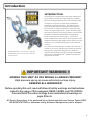
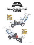
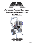
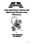
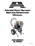
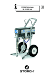
SERVICE/OPERATION
MANUAL
Form No. 001-682
MAR0405
Table of Contents
INTRODUCTION
SureStripe 4000 Specifications
Safety Warnings
1
2
GETTING STARTED
Flushing
Setting Up
Pressure Relief Procedure
Daily Maintenance
Starting Up
Striping Operation
Striping Tip Guide
7
8
9
9
10
12
13
PRODUCT DIAGRAMS &
PARTS LISTS
Gun Mount Assembly
Gearbox Assembly
Suction Assembly
Swivel Wheel Assembly
Frame Assembly
REPAIRS/MAINTENANCE
INSTRUCTIONS
Spray Gun Operation
Spray Gun Troubleshooting
Field Troubleshooting
Servicing the Fluid Pump
Servicing the Piston Rod
Servicing the Suction Assembly
Packing Replacement
Electrical Control Board
Replacement
Pressure Calibration on
the Electrical Control Board
Clutch Replacement
Troubleshooting Clutch Does
Not Engage
14
15
16
17
18
18
19
21
21
22
23
Manufactured by: AIRLESSCO BY DUROTECH CO.
P.O. Box 8006, Moorpark, CA. 93020-8006, Ship to: 5397 Commerce Ave.,
Moorpark, CA 93021 Tel: 805-523-0211 Fax: 805-523-1063
www.airlessco.com email: [email protected]
SUBJECT TO CHANGE WITHOUT NOTICE.
Copyright © 2005, All rights reserved.
24
25
25
26
27
Introduction
INTRODUCTION
The 4000 is the compact piston pump striper that delivers
the professional results and range of features needed by
pavement striping contractors—and it’s an incredible value!
It’s based on our proven LP Piston Pump used daily by
thousands of painting contractors. The large one-piece
piston along with Airlessco's patented triple-life packing
system results in reduced maintenance, lower operating
costs, and longer equipment life. A clutch actuated .8 gpm
paint system features an electronic pressure control system.
The 4000 is powered by a dependable 4 hp Honda GX
series commercial OHV 4-cycle engine. It’s built on a
small, compact frame, that’s easy to use, and quick to clean.
Designed in balance & light weight make it ideal for one-man
operation. Foot operated parking brake holds machine on
inclines.
SURESTRIPE 4000 - Part Number 305-226
SURESTRIPE 4000 - Part Number 305-227
w/swivel wheel
Our Contractor Series spray gun can spray up to .029” tip. It
mounts on any corner, and has a quick release for painting
parking curbs or pavement using stencils. It features a
tungsten carbide ball and seat, the “No Drips” REV-GUARD™
base, and our patented REV-TIP™ reversible tips that clear
clogs literally in a snap.
IMPORTANT WARNING !!
HANDLE THIS UNIT AS YOU WOULD A LOADED FIREARM!!
High pressure spray can cause extremely serious injury.
OBSERVE ALL WARNINGS!
Before operating this unit, read and follow all safety warnings and instructions
related to the usage of this equipment. READ, LEARN, and FOLLOW the
Pressure Relief Procedure on Page 9 and understand all warnings on
pages 2 thru 6.
All Service Procedures to be performed by an Authorized Airlessco Service Center ONLY.
NO MODIFICATIONS or alterations of any Airlessco Equipment or part is allowed.
1
Safety Warnings
TOXIC FLUID HAZARD
Hazardous fluid or toxic fumes can cause serious injury or death if splashed in eyes or on skin, inhaled or swallowed. Know
the hazards of the fluid you are using. Store & dispose of hazardous fluids according to manufacturer, local, state & national
guidelines. ALWAYS wear protective eye wear, gloves, clothing and respirator as recommended by fluid manufacturer.
ALWAYS INSPECT SPRAYING AREA
• ALWAYS keep spraying area free from obstructions.
• ALWAYS make sure area has good ventilation to safely remove vapors and mists.
• NEVER keep flammable material in spraying area.
• NEVER spray in vicinity of open flame or other sources of ignition.
SPRAY GUN SAFETY
•
•
•
•
•
ALWAYS set safety lock on the gun in "LOCKED" position when not in use and before servicing or cleaning.
NEVER remove or modify any part of the gun.
ALWAYS REMOVE SPRAY TIP when cleaning. Flush unit with LOWEST POSSIBLE PRESSURE.
ALWAYS check operation of all gun safety devices before each use.
Be very careful when removing the spray tip or hose from gun. A plugged line contains fluid under pressure. If the tip or
line is plugged, follow the PRESSURE RELIEF PROCEDURE as outlined on page 9.
TIP GUARD
ALWAYS have the tip guard in place on the spray gun while spraying. The tip guard alerts you to the injection hazard and helps
prevent accidentally placing your fingers or any part of your body close to the spray tip.
SPRAY TIP SAFETY
Use extreme caution when cleaning or changing spray tips. If the spray tip clogs while spraying, engage the gun safety latch
immediately.
• ALWAYS follow the PRESSURE RELIEF PROCEDURE and then remove the spray tip to clean it.
• NEVER wipe off build up around the spray tip.
• ALWAYS remove tip & tip guard to clean AFTER pump is turned off and the pressure is relieved by following the
PRESSURE RELIEF PROCEDURE.
KEEP CLEAR OF MOVING PARTS
Keep clear of moving parts when starting or operating the sprayer. Do not put your fingers into any openings to avoid
amputation by moving parts or burns from hot parts.
Precaution is the best insurance against an accident.
When starting the engine, maintain a safe distance from moving parts of the equipment.
Before adjusting or servicing any mechanical part of the sprayer, follow the PRESSURE RELIEF PROCEDURE, and remove
the ignition cable from the spark plug to prevent accidental starting of the sprayer.
LABELING
Keep all labels on the unit clean and readable. Replacement labels are available from the manufacturer.
2
Safety Warnings
HIGH PRESSURE SPRAY CAN CAUSE EXTREMELY SERIOUS INJURY.
OBSERVE ALL WARNINGS. THIS SPRAYER IS FOR PROFESSIONAL USE ONLY.
INJECTION HAZARD
Fluids under high pressure from spray or leaks can penetrate the skin and cause extremely serious
injury, including the need for amputation.
• NEVER point the spray gun at anyone or any part of the body.
• NEVER put hands or fingers over the spray tip. Do not use a rag or any other material over your fingers. Paint will
penetrate through material and into the hand.
• NEVER try to stop or deflect leaks with your hand or body.
• NEVER try to "blow back" paint, this is not an air spray sprayer.
• ALWAYS have gun tip guard in place when spraying.
• ALWAYS lock gun trigger when you stop spraying.
• ALWAYS remove tip from the gun to clean it.
• ALWAYS follow the PRESSURE RELIEF PROCEDURE, as shown on page 9, before cleaning or removing the
spray tip or servicing any system equipment.
• ALWAYS Be sure equipment safety devices are operating properly before each use.
• ALWAYS tighten all fluid connections before each use.
MEDICAL TREATMENT
If any fluid appears to penetrate your skin, get EMERGENCY CARE AT ONCE. DO NOT TREAT AS A SIMPLE CUT.
* Go to an emergency room immediately.
* Tell the doctor you suspect an injection injury.
* Tell him what kind of material you were spraying with and have him read NOTE TO PHYSICIAN.
MEDICAL ALERT - Airless Spray Wounds
If any fluid appears to penetrate your skin, get
EMERGENCY MEDICAL CARE AT ONCE. DO
NOT TREAT AS A SIMPLE CUT. Tell the doctor
exactly what fluid was injected. Have him read
the following "NOTE TO PHYSICIAN".
NOTE TO PHYSICIAN:
Injection in the skin is a traumatic injury.
It is important to treat the injury surgically
as soon as possible. DO NOT DELAY treatment
to research toxicity. Toxicity is a concern with
some exotic coatings injected directly into the
bloodstream. Consultation with a plastic surgeon or
reconstructive hand surgeon may be advisable.
GENERAL PRECAUTIONS
• NEVER alter equipment in any manner.
• NEVER smoke while in spraying area.
• NEVER spray highly flammable materials.
• NEVER use around children.
• NEVER allow another person to use sprayer unless they are thoroughly instructed on safety use and
given this operators manual to read.
• ALWAYS wear a spray mask, gloves and protective eye wear while spraying.
• ALWAYS ensure fire extinquishing equipment is readily available and properly maintained.
NEVER LEAVE SPRAYER UNATTENDED WITH PRESSURE IN THE SYSTEM. FOLLOW PRESSURE RELIEF
PROCEDURES ON PAGE 9.
3
Safety Warnings
GROUNDING
Ground the sprayer and other components in the system to reduce the risk of static sparking, fire or explosion which can
result in serious bodily injury and property damage.
Always ground all of these components:
• Sprayer: Be sure grounding chain (supplied) is in contact with the ground.
• Fluid Hose: use only grounded hoses.
• Spray gun or dispensing valve: grounding is obtained through connection to a properly
grounded fluid hose and pump.
• Object being sprayed: according to your local code.
• All solvent pails used when flushing should only be metal pails which are conductive.
Once each week, check electrical resistance of hose (when using multiple hose assemblies, check overall resistance of
un-pressurized hose must not exceed 29 megohms (max) for any coupled length or combination of hose lengths. If hose
exceeds these limits, replace it immediately.
Never exceed 500 Ft. (150 m.) overall combined hose length to assure electrical continuity.
AVOID COMPONENT RUPTURE
This sprayer operates at 3000 psi (205 bar). Always be sure that all components and accessories have a
maximum working pressure of at least 3000 psi to avoid rupture which can result in serious bodily injury
including injection and property damage.
• NEVER leave a pressurized sprayer unattended to avoid accidental operation of it which could result in serious
bodily injury.
• ALWAYS follow the PRESSURE RELIEF PROCEDURE whenever you stop spraying and before adjusting,
removing or repairing any part of the sprayer.
• NEVER alter or modify any part of the equipment to avoid possible component rupture which could result in
serious bodily injury and property damage.
• NEVER use weak, damaged or non-conductive paint hoses. Do not allow kinking or crushing of hoses or allow
it to vibrate against rough, sharp or hot surfaces. Before each use, check hoses for damage and wear and ensure
all fluid connections are secure.
• REPLACE any damaged hose. NEVER use tape or any device to mend the hose.
• NEVER attempt to stop any leakage in the line or fittings with your hand or any part of the body. Turn off the
unit and release pressure by following PRESSURE RELIEF PROCEDURE on page 9,.
• ALWAYS use approved high pressure fittings and replacement parts.
• ALWAYS ensure fire extinquishing equipment is readily available and properly maintained.
Do not use halogenated solvents in this system. Most airless guns have aluminum parts and may
explode. Cleaning agents, coatings, paints or adhesives may contain halogenated hydrocarbon
solvents. DON'T TAKE CHANCES! Consult your material suppliers to be sure.
Some of the most common of these solvents are:
Carbontetrachloride, Chlorobenzene, Dichloroethane, Dichloroethyl Ether,
Ethylbromide, Ethylchloride, Tethrachloethane.
Alternate valves & guns are available if you need to use these solvents.
4
Safety Warnings
FLUSHING
Reduce risk of injection injury, static sparking or splashing by following the specific cleaning
procedure on page 5.
ALWAYS follow the PRESSURE RELIEF PROCEDURE on page 9.
ALWAYS remove the spray tip before flushing. Hold a metal part of the gun firmly to the side of a metal pail and
use the lowest possible fluid pressure during flushing.
NEVER use cleaning solvents with flash points below 140º F. Some of these are: acetone, benzene, ether,
gasoline and naphtha. Consult your supplier to be sure.
NEVER smoke in the spraying/cleaning area.
•
•
•
•
PREVENT STATIC SPARKING FIRE/ EXPLOSIONS
ALWAYS be sure all equipment and objects being sprayed are properly grounded. Always ground sprayer, paint bucket and
object being sprayed. See "grounding" on page 4 for detailed grounding information.
Vapors created when spraying can be ignited by sparks. To reduce the risk of fire, always locate the sprayer at least 20 feet (6
m.) away from the spray area. Do not plug in or unplug any electrical cords in the spray area, this can create sparks when there
is any chance of igniting vapors still in the air. Follow the coating & solvent manufacturers safety warnings and precautions.
Use only conductive fluid hoses for airless applications. Be sure gun is grounded through hose connections. Check ground
continuity in hose & equipment. Overall (end to end) resistance of un-pressurized hose must not exceed 29 megohms for any
coupled length or combination of hose length. Use only high pressure airless hoses with static wire approved for 3000 psi.
Important: United States Government safety standards have been adopted under the Occupational
Safety & Health Act. These standards, particularly the General Standards, Part 1910, & the
Construction Standards, part 1926 should be consulted.
WHEN SPRAYING & CLEANING WITH FLAMMABLE PAINTS OR PAINT THINNERS:
•
•
•
•
•
When spraying with flammable liquids, unit must be located a minimum of 25 feet away from spraying area
in a well ventilated area. Ventilation must be sufficient enough to prevent the accumulation of vapors.
To eliminate electrostatic discharge, ground the spray unit, paint bucket and spraying object. Use only high
pressure airless hoses approved for 3000 psi which is conductive.
Remove spray tip before cleaning gun and hose. Make contact of gun with bucket and spray without the tip in
a well ventilated area, into the grounded steel bucket.
Never use high pressure in the cleaning process. USE MINIMUM PRESSURE.
Do not smoke in spraying/cleaning area.
GAS ENGINE PRECAUTIONS
Gasoline & its vapors are extremely
flammable & explosive.
Fire or explosion can cause severe burns or death.
WHEN ADDING FUEL
• Turn engine OFF and let engine cool at least 2
minutes before removing gas cap.
• Fill fuel tank outdoors or in well ventilated area.
• Do not overfill fuel tank. Fill tank to approximately
11⁄2 inches below top of neck to allow for fuel
expansion.
• Keep gasoline away from sparks, open flames, pilot
lights, heat and other ignition sources.
• Check fuel lines, tank, cap and fittings frequently for
cracks or leaks. Replace if necessary.
WHEN STARTING ENGINE
• Make sure spark plug, muffler, fuel cap and air cleaner
are in place.
• Do not crank engine with spark plug removed.
• If fuel spills, wait until it evaporates before starting
engine.
• If engine floods, set choke to OPEN/RUN
position, place throttle in FAST and crank until
engine starts.
WHEN OPERATING EQUIPMENT
• Do not tip engine or equipment at angle which
causes gasoline to spill.
• Do not choke carburetor to stop engine.
WHEN TRANSPORTING EQUIPMENT
• Transport with fuel tank EMPTY or with fuel shut-off
valve OFF.
5
Safety Warnings
WHEN STORING GASOLINE OR EQUIPMENT WITH FUEL
IN TANK
• Store away from furnaces, stoves, water heaters and
other appliances that have pilot lights or other ignition
source. They can ignite gasoline vapors.
Starting engine creates sparking.
Sparking can ignite nearby flammable gases.
Engines give off carbon monoxide, an odorless,
colorless, poison gas.
Breathing carbon monoxide can cause nausea,
fainting or death.
• Start and run engine outdoors.
• Do not start or run engine in enclosed area, even if doors or
windows are open.
Explosion and fire could result.
• If there is natural or LP gas leakage in area, do not
start engine.
• Do not use pressurized starting fluids because vapors
are flammable.
Rapid retraction of starter cord (kickback) will pull
hand and arm toward engine faster than you can let go.
Broken bones, fractures, bruises or sprains could result.
• When starting engine, pull cord slowly until resistance is
felt, then pull rapidly.
• Remove all external equipment/engine loads before starting
engine.
• Direct coupled equipment components such as, but not
limited to, blades, impellers, pulleys, sprockets, etc. must
be securely attached.
Running engines produce heat. Engine parts,
especially mufflers, become extremely hot.
Severe thermal burns can occur on contact.
Combustible debris, such as leaves, grass, brush,
etc. can catch fire.
• Allow muffler, engine cylinder and fins to cool before
touching.
• Remove accumulated combustibles from muffler area and
cylinder area.
• Install and maintain in working order a spark arrester
before using equipment on forest covered, grass covered
and brush covered unimproved land. The state of
California requires this (Section 4442 of the California
Public Resources Code). Other states may have similar
laws. Federal laws apply on federal land.
Unintentional sparking can result in fire
or electric shock.
Rotating parts can contact or entangle hands, feet,
hair, clothing or accessories.
Traumatic amputation or severe laceration can result.
•
•
•
•
6
Operate equipment with guards in place.
Keep hands and feet away from rotating parts.
Tie up long hair and remove jewelry.
Do not wear loose fitting clothing, dangling drawstrings or
items that could become caught.
Unintentional start up can result in entanglement,
traumatic amputation, or lacerations.
BEFORE PERFORMING ADJUSTMENTS OR REPAIRS
• Disconnect spark plug wire and keep it away from
spark plug.
• Disconnect battery at negative terminal (only
engines with electric start).
WHEN TESTING FOR SPARK
• Use approved spark plug tester.
• Do not check for spark with spark plug removal.
Flushing
IMPORTANT: Read Prior to Using Your Sprayer
1. New Sprayer
Your Airlessco unit was factory tested in an antifreeze solution which was left in the pump.
Before using oil-base paint, flush with mineral spirits only. Before using water-base paint
flush with soapy water, then do a clean water flush.
2. Changing Colors
Flush with a compatible solvent such as mineral spirits or water.
3. Changing from water-base to oil-base paint
Flush with soapy water, then mineral spirits.
4. Changing from oil-base to water-base paint
Flush with mineral spirits, followed by soapy water, then do a clean water flush.
5. Storage
Oil-base paint: Flush with mineral spirits.
Water-base paint: Flush with water, then mineral spirits and leave the pump, hose and gun
filled with mineral spirits. For longer storage, use mixture of mineral spirits and motor oil
(half & half). Shut off the sprayer, follow Pressure Relief Procedure on page 9 to relieve
pressure and make sure prime valve is left OPEN.
6. Start up after storage
Before using water-base paint, flush with soapy water and then do a clean water flush. When
using oil-base paint, flush out the mineral spirits with the material to be sprayed.
7
Daily Maintenance
1. Keep the displacement pump packing nut/wet cup lubricated with Airlessco TSO
(Throat Seal Oil) at all times. The TSO helps protect the rod and the packings.
Airlessco Throat Seal Oil
6 ounce bottle Part # 188-187
1 quart bottle Part # 188-392
2. Inspect the packing nut daily. Your pump has Airlessco’s patented Triple Life Packing System.
Packing life will be extended a minimum of three times if the
following "Packing Adjustment" procedure is followed:
If seepage of paint into the packing nut and/or movement of the piston upward is found (while not
spraying), the packing nut should be tightened enough to stop leakage only, but not any tighter.
Overtightening will damage the packings and reduce the packing life.
3. Check suction nut daily.
8
Pressure Relief Procedure
IMPORTANT!
To avoid possible serious body injury, always follow this procedure whenever the
sprayer is shut off, when checking it, when installing, changing or cleaning tips,
whenever you stop spraying, or when you are instructed to relieve the pressure.
1. Engage the gun safety latch. Refer to the
separate instruction manual provided with
your gun on its safety features and how to
engage safety latch.
2. Turn the unit off.
3. Disengage the gun safety latch and trigger
the gun to relieve residual fluid pressure.
Hold metal part of the gun in
contact with grounded metal pail.
USE MINIMUM PRESSURE !
4. Turn Prime/Pressure Relief Valve (PR Valve)
to the open (priming) position to relieve
residual fluid pressure.
There will be a wider gap between valve
handle and cam body when in open
position. In the closed position there is
only a very slight gap.
.
Note: The valve handle can move both
clockwise and counter clockwise and can
face different directions.
5. Re-engage gun safety latch and
close Prime/Pressure Relief Valve.
If the SPRAY TIP OR HOSE IS CLOGGED, follow Step 1 through 5 above. Expect paint
splashing into the bucket while relieving pressure during Step 4.
If you suspect that pressure hasn't been relieved due to damaged Prime/Pressure
Relief Valve or other reason, engage the gun safety latch and take your unit to an
authorized Airlessco Service Center.
9
Starting Up
1. Learn the Functions
of the Controls.
PRIME/PRESSURE (PR) RELIEF VALVE is used to
prime pump and to relieve pressure from gun, hose and tip.
Prime/Pressure Relief Valve (Prime/PR Valve)
Used to relieve pressure from gun, hose & tip and to prime
the unit when in OPEN position. (It is in open position
when there is a wider gap
between valve handle and
cam body)
When in CLOSED position,
there is only a very slight gap
between handle & body.
When closed the system is
pressurized. Handle as a loaded firearm!
4. Adjusting the Pressure
a. Turn the Pressure Control Knob Clockwise to
increase pressure and counterclockwise to decrease
pressure.
b. Always use the lowest pressure necessary to
completely atomize the material.
Note: Operating the sprayer at higher pressure
than needed, wastes material, causes early tip
wear, and shortens sprayer life.
c. If more coverage is needed, use a larger tip rather
than increasing the pressure.
d. Check the spray pattern. The tip size and angle
determines the pattern width and flow rate.
PRESSURE CONTROL KNOB is used to adjust
pressure. Turn clockwise (CW) to increase pressure
and counterclockwise (CCW) to
decrease pressure.
2. Prepare the Material
a. Prepare the material according to the material
manufacturer's recommendations.
b. Place the suction tube into the material
container.
3. Starting the Sprayer
a. Prime/PR Valve must be "OPEN" in the priming
position.
b. When you have ensured that the gun safety latch
is engaged, attach tip and safety guard.
c. Turn the engien ON/OFF switch to the
"ON" position.
d. Turn Pressure Control Knob clockwise to prime
the pump.
e. After the pump is primed, turn Prime/PR Valve to
the "Closed" position.
f. Turn Pressure Control Knob to the desired spray
pressure.
g. Disengage the gun safety latch and you are
ready to spray.
10
Starting Up
Follow the "Pressure Relief Procedure".
To reduce the risk of injection, never hold
your hand, body, fingers or hand in a rag
in front of the spray tip when cleaning
or checking for a cleared tip. Always
point the gun toward the ground or into a
waste container when checking to see if
the tip is cleared or when using a
self-cleaning tip.
When you spray into the paint bucket,
always use the lowest spray pressure
and maintain firm metal to metal contact
between gun and container.
Avoiding Tip Clogs
There is an easy way to keep the outside of the
tip clean from material build up:
Every time you stop spraying, for even a minute,
lock the gun and submerge it into a small bucket
of thinner suitable for the material sprayed.
Thinner will dissolve the buildup of paint on the
outside of tip, tip guard and gun much more
effectively if the paint doesn't have time to dry
out completely.
Be sure to relieve pressure in
the pump after filling with Airlessco
Pump Conditioner.
5. When Shutting off the Sprayer
To stop the unit in an emergency, turn the
engine off. Then relieve the fluid pressure
in the pump and hose as instructed in the
Pressure Relief Procedure.
a. Whenever you stop spraying, even for a short break,
follow the "Pressure Relief Procedure".
b. Clean the tip & gun as recommended in the seperate
Gun Manual supplied with the gun/
c. Flush the sprayer at the end of each work day, if the
material you are spraying is water-based, or if it could
harden in the sprayer overnight. See "Flushing". Use a
compatible solvent to flush, then fill the pump and hoses
with an oil based solvent such as mineral spirits.
d. For long term shutdown or storage, refer to the
"Flushing" section of this manual.
11
Striping Operation
1. Choose handle location
The choices are, installing the handle opposite
of the single wheel assembly (standard set up)
or placing the handle directly over the single
wheel assembly. The handle location is really
a matter of personal preference, however
having the handle away from the single wheel
assembly allows for easier loading/unloading
from a van.
2. Choose the gun arm position
There are multiple holes in the frame for
mounting the gun arm. In a standard set up
(handle away from the single wheel assembly),
the gun arm would be mounted in one of the
two mounting holes near the single wheel. This
allows for an easier visual check for straight
line striping and for basic arc striping. The
mounting holes under the handle are usually
used when the handle has been placed over
the single wheel. Experiment with different
combinations to find the set up that you prefer.
3. Setting up the gun
a. Ensure that a striping tips is in the guns.
b. Pick a tip size for the desired line width.
Example: a 217ST tip for a four inch line.
c. Place gun into the gun holder, so that the
top of the taper on the gun handle is flush
with the edge of the gun holder.
d. Set gun height for the desired line width.
Adjust height by loosening the small black
handle on the gun holder assembly and
slide the gun arm to the correct height. Now
tighten the handle. This will require some
experimentation to find the correct height.
It is suggested that tape, or some other
method is used to mark the height of
commonly used settings.
e. Attach the swivel heads to the gun if
painting curbs or wide stripes.
f. Angle the gun slightly forward. This
allows the spray pressure from the gun to
help blow dirt and debris out of the path of
the new stripe.
4. Cable Tension Adjustment
Once the handle and gun arm assemblies are set up to
the preferred position, pressurize the unit and trigger
the gun to ensure that they activate and release
correctly. If not, adjust the cable tension as follows:
a. Locate the adjustment knobs on the base of the
gun trigger, where the cable connects to the gun
trigger assembly.
b. Loose the locking nut & move the adjusting screw
until the slack has been removed from the cable.
c. Tighten locking nut and retest gun triggers for
proper function.
NOTE: There is additional cable adjustment
where the cable attaches to the gun
holder assembly. Use only if the gun
trigger adjustment is insufficient.
5. Miscellaneous Operations
a. CURBS: Adjust gun to desired height and turn
swivel head towards curb.
b. WIDE STRIPES: Install wider fan striping tips
and raise the gun height to achieve the desired
width line.
c. STENCILS: Install standard spray tip. Remove
gun from the gun holder and spray out the
stencils.
d. STANDARD PAINTING: Same as stencils, but
use additional paint hose as required.
Inserting REV-TIP™ & seal into REV-GUARD™
12
Striping Tip Guide
Rev-Tip for Striping
STRIPING TIP - ORIFICE SIZE (Inches)
TM
Fan Width (6” from surface)
(mm)
in
25-51
1-2
2-4
4-6
6-8
.015
.011 .013
.009
.017
.021
.019
.023
.025
.027
Latex
Latex
Latex
.031 .035
113ST 115ST 117ST 119ST
51-102
215ST 217ST 219ST 221ST
102-152
152-203
315ST 317ST 319ST 321ST
Oil Base Oil Base Latex
Striping Paint
Latex
Latex
Water Flow Rate (gpm)
(water @ 2000psi, 138 bar)
(lpm)
.12
.49
.18
.69
.24
.91
.31
1.17
.38
1.47
.47
1.79
.57 .67
2.15 2.54
.77 1.03 1.31 1.63 1.80
2.96 3.90 4.98 6.17 6.81
Paint Flow Rate (gpm)
(latex paint @ 2000psi,
(lpm)
138 bar/1.36 spec. gr.)
.10
.38
.15
.57
.21
.79
.27
1.02
.33
1.25
.40
1.51
.49 .58
1.85 2.20
.66 .88 1.12 1.39 1.54
2.50 3.33 4.24 5.26 5.83
Pump Minimum (gpm)
(lpm)
Output*
.25
1.0
.25
1.0
.33
1.25
.40
1.5
.50
1.9
.60
2.3
.75
2.8
*Pump will support tip worn to next larger size.
REV-TIP
M
T
TM
1.5
5.7
2.0
7.5
2.2
8.2
TM
Super Compact
P.N. 561-001
11/16-16 “F” Thread. Fits:
Airlessco, and some ASM,
Wagner, and Campbell Hausfeld.
1/2 Fan Width
P.N. 561-002
7/8-14 “G” Thread.
Fits some: Graco, Wagner,
Titan, Airlessco.
560-215
REV-TIP
1.25
4.7
1.0
3.8
REV-GUARD
for Striping
P.N. 562-xxxST
Includes Rev-TipTM, Metal Seal
& O-Ring Seal.
Sample:
.88
3.3
Orifice Size
Striping Tips (orange handle) should not be used for regular spraying. They are designed for a single
pass application, while spray tips (black handle) are designed for the 1/3 overlap technique used for
spray painting.
Spray Tip Replacement: During use high pressure will cause the orifice to grow larger and more round. This
destroys the efficiency of the pattern, wasting your material. It can also leave tailing or two heavy lines on the
outside of the pattern.
REGULAR PAINTING SPRAY TIP
LIGHT
HEAVY
STRIPING TIP
LIGHT
UNIFORM PATTERN
13
Spray Gun Operation
SPRAY GUN
Attach spray gun to airless unit and tighten fittings securely.
Set the gun safety latch. (Also may be called gun safety
lock, or trigger lock)
* The gun safety latch should always be set when the gun is
not being triggered.
Read all warnings and safety precautions supplied with the
spray gun and in product manual.
MAJOR COMPONENTS OF SPRAY GUN &
REVERSIBLE REV-TIP™
™
Reversible
Spray Tip
Tip Guard
Gun Safety
Latch or Lock
Trigger Guard
Gun Handle. Unscrew
from gun head to service
filter inside.
Press up here & pull gently
to remove trigger guard
SPRAY TIP ASSEMBLY
1. Be sure the pressure relief procedure is followed
before assembling tip and housing to the gun.
2. Insert REV-TIP™ cylinder into the REV-GUARD™
(guard housing assembly).
3. Guide the metal seat into REV-GUARD™ (guard
housing assembly) through the retaining nut and turn
until it seats against the cylinder.
4. Insert the O-Ring gasket onto the metal seat so that it
fits into the grooves.
5. Finger tighten REV-GUARD™ retaining nut onto the gun.
6. Turn guard in the desired position.
7. Completely tighten the retaining nut.
Retaining Nut
REV-GUARD™
Guard Housing Assembly
O-Ring Gasket
Metal Seat
TO REMOVE CLOGS FROM SPRAY TIP
1. Lock gun safety latch.
2. Turn REV-TIP™ handle 180 degrees.
3. Disengage trigger lock and trigger gun into
the pail.
4. If the REV-TIP™ handle appears locked
(resists turning), loosen the retaining nut. The
handle will now turn easily.
5. Engage gun safety latch and return handle to
the spray position.
Retaining Nut
Reverse to
Unplug
Spray Position Shown
REV-TIP™ Cylinder
CLEANING SPRAY GUN
Immediately after the work is finished, flush the gun out
with a solvent. Brush pins with solvent and oil them
lightly so they will not collect dried paint.
CLEANING FILTER IN GUN HANDLE
To clean the filter, use a brush dipped in an appropriate solvent. Change or clean filters at least once a day.
Some types of latex may require a filter change after
14 four hours of operation.
CLOGGED FLAT TIP
Should the spray tip become clogged, relieve
pressure from hose by following the "Pressure Relief Procedure." Secure gun with the safety latch,
take off guard, take out the tip, soak in appropriate
solvent & clean with a brush. (Do not use a needle
or sharp pointed instrument to clean the tip. The
tungsten carbide is brittle and can chip.)
Spray Gun Troubleshooting
DEFECTS
CAUSE
CORRECTION
Coarse spray
Low pressure
Increase the pressure
Excessive fogging
(overspray)
High pressure
Material too thin
Reduce pressure for satisfactory pattern
Use less thinner
Pattern too wide
Spray angle too large
Use smaller spray angle tip
Pattern too narrow
Spray angle too small
Use larger spray angle tip. (If coverage is OK,
try tip in same nozzle group)
Too much material
Tip size too large
Material too thin
Pressure too high
Use next smaller tip
Too little material
Tip size too small
Material too thick
Use next larger tip
Thin distribution in
center of pattern
"horns"
Worn tip
Wrong tip
Change for new tip
Use tip with a smaller spray angle
Thick skin on work
Material too viscous
Thin material
Application too heavy
Reduce pressure and/or use smaller tip
Coating fails to
close & smooth over
Material too viscous
Thin material
Spray pattern irregular,
deflected
Orifice clogged
Tip damaged
Clean carefully
Replace with new tip
Craters or pock marks
Solvent balance
Use 1-3% "short" solvents remainder "long"
solvents. (This is most likely to happen with
material of low viscosity, lacquers etc.)
Bubbles on work
Contamination or dust
Clean surface to be sprayed
Clogged screens
Extraneous material
in paint.
Clean screen
Coarse pigments
Use coarse screen if orifice size allows
Poorly milled pigments
(paint pigments glocculate
cover screen. Incompatible
Use coarser screen, larger orifice tips. Obtain ball
milled paint. If thinner was added, test to see if a
drop on top of paint mixes or flattens out on
paint mixture & thinners.
TEST THE PATTERN
Reduce pressure
on the surface. If not, try different thinner
in fresh batch of paint.
15
Field Troubleshooting
PROBLEM
Unit doesn't prime
CAUSE
Airleak due to:
• Loose Suction Nut
• Worn O-Rings
• Hole in Suction Hose
Unit primes but has no
or poor pressure
Unit does not maintain
good spraying pressure
16
SOLUTION
• Tighten Suction Nut
• Replace O-Ring (106-011) on
suction seat, & O-Ring (106020) below suction seat
• Replace Suction Hose (331-290)
Stuck or Fouled Balls
Service outlet valve suction
assembly
Pressure set too low
Turn up pressure
Filter(s) are clogged
Clean or replace gun filter, inlet
filter and/or manifold filter
Outlet Valve fouled/worn
Service outlet valve
Prime/Pressure Relief valve
bypassing
Clean or replace prime valve
Packings and/or piston worn
Tighten packing nut
Repack unit
Blown spray tip
Replace spray tip
Packings and/or piston worn
Repack unit
Upper Seat worn
Replace upper seat
Servicing the Fluid Pump
Fluid Pump Disconnect
Fluid Pump Reinstall
Refer to Figure 1 & 4
Refer to Figure 1
1.
2.
3.
4.
5.
6.
7.
8.
9.
Follow the Pressure Relief Procedure on page 9.
Flush the material you are spraying out of the machine.
Remove the connecting rod shield (331-111).
Move the piston rod (331-093) to its lowest position
by cycling pump slowly.
Disconnect the sensor (331-294-99) by holding it in
place with a 11/16” wrench and unscrewing the hose
connector (115-019) with an 9/16” wrench.
DO NOT TURN THE SENSOR.
Remove the retaining ring (331-062) from the
connecting rod (331-038) and slide the sleeve (331117) down revealing the connecting rod pin (331-065).
Remove the suction tube assembly from the fluid
pump (331-209) by unscrewing the suction nut
(331-034) with the packing adjustment tool.
Using a 1/2” wrench unscrew the two bolts (100-318)
from the cover assembly (331-234). The fluid pump
(331-209) will be hanging loosely at this point.
Remove the connecting rod pin (331-065) out of
the connecting rod (331-038), allowing the removal
of the fluid pump (331-209) from the machine.
FIGURE 1
1. Loosen the packing nut and ensure that the piston rod
(331-093) is in its upper position in the fluid pump body
(331-011). Slip the sleeve (331-117) & the retaining
ring (331-062) over the piston rod.
2. Push the piston rod up into the connecting rod (331038) & align the holes. Insert the connecting rod pin
(331-065) through the connecting rod & piston. Slip
the sleeve up over the connecting rod pin and insert
the retaining ring into the groove on the connecting rod.
3. Push the two bolts (100-318) through the tube spacers
(331-074) & screw them into the cover assembly (331234). Using a 1/2” wrench, tighten the two bolts evenly
(alternating between them) until you reach 20 ft-lbs.
4. Reassemble lower suction valve assembly by placing
the suction seat (331-409), O-ring (106-011), suction
ball (331-030) & suction ball guide (331-029) in the
suction nut (331-034) & screw onto fluid pump body.
5. Reconnect the sensor (331-294-99) to the fluid pump
body. Hold the sensor with a 11/16” wrench while
tightening the hose connector (115-019) with an
9/16” wrench. DO NOT TURN THE SENSOR.
6. Start the machine and operate slowly to check the piston
rod for binding. Adjust the two bolts, holding the fluid
pump body to the cover assembly, if necessary. This
will eliminate any binding.
7. Tighten the packing nut clockwise until resistance is
felt against the Belleville Springs, then go 3/4 of a turn
more. Put five drops of Airlessco Throat Seal Oil into the
packing nut.
8. Run the machine at full pressure for several minutes.
Release the pressure by following the Pressure Relief
Procedure & readjust the packing nut per step 7 above.
9. Install the connecting rod shield (331-111) so that the
small hole is in the upper right hand corner.
Hose Connector 115-019
Swivel 100-152
17
Servicing the Piston Rod - Outlet Valve
FIGURE 3
DISASSEMBLY OF THE OUTLET VALVE
REFER TO FIGURE 3
1. Disconnect the Fluid Pump following instructions on page 17 .
2. Place piston holder (331-195) in a vise. Slide piston into
the holder & lock in place with a 3/8” dowel (331-196).
3. Use a 1/4” allen wrench to unscrew the outlet seat retainer
(331-026) from the piston.
4. Remove the outlet seat (331-026), O-ring (331-100) and
outlet ball (331-027).
5. Inspect outlet ball & seat for wear. Replace as necessary.
6. While piston is still locked in the holder, install parts
back into the piston in the following order:
Piston
331-195
331-196
ball, outlet seat and O-ring
Before reinstalling the outlet seat support, apply two drops of Loctite No.
242 (blue) on the threads & torque to 20 ft-lbs.
NOTE: Airlessco LP pump tool kit 188-197 is suggested for this task.
Kit includes: Tightening Bar (189-211), Packing Removal Tool (331-465),
Piston Holder (331-195), 3/8” dowel (331-196).
Servicing the Suction Assembly
REFER TO FIGURE 4
1. Un-thread and remove suction nut from the fluid pump body.
2. Remove suction seat (331-409), O-ring (106-011), suction ball
(331-030) and suction retainer (331-029).
3. Clean all parts and inspect them for wear or damage, replacing
parts as needed.
4. Clean inside of the fluid pump body.
5. Reassemble lower suction valve assembly by placing the
suction seat (331-409), O-ring (106-011), suction ball (331-030)
& suction ball guide (331-029) in the suction nut (331-034) &
screw onto fluid pump body.
18
FIGURE 4
Packing Replacement Procedures
Fluid Pump Removal - Refer to Figure 1
1. Follow the Pressure Relief Procedure on page 9.
2. Flush material you are spraying out of the machine.
3. Remove the connecting rod shield (331-111).
4. Move the piston rod (331-093) to its lowest position by
cycling pump slowly.
5. Disconnect the sensor (331-294-99) by holding it in place
with a 11/16” wrench & unscrewing the hose connector
(115-019) with an 9/16” wrench.
DO NOT TURN THE SENSOR.
6. Remove the retaining ring (331-062) from the connecting
rod (331-038) and slide the sleeve (331-117) down
revealing the connecting rod pin (331-065).
7. Remove the suction tube assembly from the fluid pump
(331-209) by unscrewing the suction nut (331-034) with the
packing adjustment tool.
9. Remove the connecting rod pin (331-065) out of the
connecting rod (331-038), allowing the removal of the fluid
pump (331-209) from the machine.
2. Take three of the lower polyethylene packings (331-016) & two
of the leather packings (331-306) & place onto the male gland in
the following order with the inverted side down :
Polyethylene, leather, polyethylene, leather, polyethylene.
3. Take the female adaptor (331-305), which is inverted on both
sides
, & place it on top of your assembled lower packings.
4. Follow step 2 above with your packings inverted side up.
5. Take the second lower male gland and place it on top of your
assembled packings with the rounded side down.
6. Take assembled glands & packings (13 pieces) & slide on to the
lower half of the piston.
7. Take the spacer (331-018) & slide over the top of the piston (it
doesn’t matter which direction it sits), falling onto lower packings.
8. Take three Belleville Springs (331-025) & slide over the top of
the piston in the following order:
* First spring, curve facing down
* Second spring, curve facing up
* Third spring, curve facing down
( (
8. Using a 1/2” wrench unscrew the two bolts (100-318) from
the cover assembly (331-234). The fluid pump (331-209)
will be hanging loosely at this point.
REASSEMBLY - Figure 5 & 6
1. Take lower male gland (331-014) & place it down on
the flat side.
(
Replacement Instructions:
9. Take the upper male gland (331-022) & place it rounded side up.
1. Unscrew & remove the packing nut (331-037).
10. Take three upper polyethylene packings (331-023) & two leather
packings (331-307) & assemble with inverted side down
,
on to the male gland in the following order:
polyethylene, leather, polyethylene, leather, polyethylene.
2. Push the piston rod (331-708) down through the packings
& out of the pump.
11. Take upper female gland (331-021) & place on top of the assembled
upper packings with the inverted side down.
3. Now push the packing removal tool (331-465) up through
the pump & remove from the top bringing packings, spacer
& springs along with it, leaving fluid body (331-011) empty.
12. Take assembled upper glands & packings (7 pieces) & slide on
over the top of the piston, making sure inverted sides are down.
Disassembly of the Fluid Pump - Figure 6
*Make sure all old packings & glands have been removed from fluid pump.
4. Clean inside of fluid body (331-011).
5. Disassemble all parts & clean for reassembly. Discard any
old packings.
6. Lubricate leather packing in lightweight oil for 10 minutes
prior to reassembly.
13. Take the packing holder (331-019) & replace the white O-ring
(106-009) & the black O-ring (106-010) with new ones from the
packing kit.
14. Slide the packing holder over the top of the upper packings
so they fit inside.
15. Lubricate inside of the fluid pump body & the outside of the
packings with a light weight oil.
16. Slide completed assembly into fluid pump body (331-011).
Disassembly of the Outlet Valve - Figure 3
* To keep packings secured in correct position, hold the pump body
1. Place piston holder (331-195) in a vise. Slide piston into the
upside down & push the completed assembly upwards into the pump
holder & lock in place with a 3/8” dowel.
body. Once placed inside, tilt pump body back up to keep all pieces in.
2. Use a 1/4” allen wrench to unscrew the outlet seat retainer
17. Tighten packing nut (331-037) onto the top of the fluid pump
(331-026) from the piston.
body & tighten until you feel slight resistance against the
3. Remove the outlet seat (331-026), O-ring (331-100) and
Belleville Springs (331-025). Using the Packing Adjustment Tool
outlet ball (331-027).
(189-211), tighten another 3/4 of a turn.
4. Inspect outlet ball & seat for wear. Replace as necessary.
Fluid Pump Reinstallation - Figure 1 & 4
1. Loosen packing nut & ensure that the piston rod (331-093) is in
5. While piston is still locked in the holder, install parts back into
its upper position in the fluid pump body (331-011). Slip the
the piston in the following order:
sleeve (331-117) & the retaining ring (331-062) over the piston rod.
ball, outlet seat and O-ring
2. Push piston rod up into the connecting rod (331-038) & align the
holes. Insert the connecting rod pin (331-065) through the
Before reinstalling the outlet seat support, apply two drops of Loctite
connecting rod & piston. Slip the sleeve up over the connecting
No. 242 (blue) on the threads & torque to 20 ft-lbs.
rod pin & insert retaining ring into the groove on the connecting rod.
19
Packing Replacement Procedures
3. Push the two bolts (100-318) through the tube spacers
(331-074) & screw into the cover assembly (331-234).
Using a 1/2” wrench, tighten the two bolts evenly
(alternating between them) until you reach 20 ft-lbs.
4. Reassemble lower suction valve assembly by placing
the suction seat (331-409) O-ring (106-011), suction
ball (331-030) and suction ball guide (331-029) in the
suction nut (331-034) & screw onto the fluid pump body.
5. Reconnect the sensor (331-294-99) to the fluid pump
body. Hold sensor with a 11/16” wrench while
tightening the hose connector (115-019) with
an 9/16” wrench.
DO NOT TURN THE SENSOR.
6. Start the machine & operate slowly to check the piston
rod for binding. Adjust the bolts, holding the fluid
pump body to the cover assembly, if necessary. This
will eliminate any binding.
7. Tighten packing nut clockwise until resistance is felt
against the Belleville Springs, then go 3/4 of a turn
more. Put five drops of Airlessco Throat Seal Oil
into the packing nut.
8. Run the machine at full pressure for several minutes.
Release the pressure by following the Pressure Relief
Procedure & readjust the packing nut per step 7 above.
9. Install the connecting rod shield (331-111) so that the
small hole is in the upper right hand corner.
FIGURE 6
20
FIGURE 5
Electrical Control Board Replacement
1. Remove electrical cover.
2. Disconnect sensor lead from Electrical Board.
3. Disconnect two clutch leads on Electrical Board
from leads on clutch.
4. Using a 1/16" allen, loosen set screw in Pressure
Control Knob and remove knob.
5. Using a 1/2" nutdriver or 1/2" deep socket, remove
nut from pressure control shaft. This will allow
removal of electrical control board from frame.
6. Replace Electrical Board Assembly in reverse order.
Adjust pressure as per procedure below, "Pressure
Calibration on the Electrical Control Board".
Pressure Calibration on the Electrical Control Board
1. Turn "Pressure Calibration" Trimpot adjustment on
electrical control board in the counter clockwise
direction at least 15 revolutions.
The pump will begin to pressurize and the clutch will disengage at a low pressure. Continue turning the Trimpot
clockwise to increase pressure to 3000 psi.
2. Connect 5000 psi glycerine pressure guage on output
of pump between fluid pump & airless hose to
monitor Fluid Pump Pressure.
5. Trigger gun. The pressure should drop approximately
350-400 psi (when using a 3/8" hose), the clutch will
engage and build pressure to 3000 psi and disengage.
Trigger gun several times to ensure proper pressure
setting.
6. Turn Pressure Control Knob to minimum position. The
clutch should disengage and pump stop moving.
7. Secure leads with tie strap.
8. Replace cover on unit. Ensure the leads are not
pinched or damaged in the process of replacing covers.
3. Turn Prime/Pressure Relief Valve to the open
(Prime) position. Start engine and run at maximum
RPM. Turn Pressure Control Knob to maximum
position (fully clockwise).
4. Using an insulated screwdriver, adjust "Pressure
Calibration" Trimpot by turning clockwise until the
clutch engages. When the clutch engages the pump
will commence Priming. When pump is primed, turn
the Prime/Pressure Relief Valve to the Closed (Pres
sure) Position
21
Clutch Replacement
REMOVE CLUTCH AS FOLLOWS:
1. Remove clutch and electrical box cover.
2. Disconnect the power lead coming from the engine
to the electrical box and feed it through the back of
the electrical box.
3. Using a 1/2” wrench along with a 1/2” socket
remove the four bolts attaching the engine to the
frame.
4. Remove the engine from the frame and set it on
your work bench so the clutch face is facing you.
5. Using a small Phillips head screwdriver remove
the three screws holding the clutch face to the
clutch mount.
6. Disconnect two clutch leads from electrical board
leads. Carefully cut the small Zip-tie holding the
clutch wires to the gear housing.
7. Using a #2 Phillips screwdriver, remove the two
Phillips head screws holding the clutch field to the
gear housing.
8. Pull the clutch field off of the pinion gear.
INSTALL NEW CLUTCH AS FOLLOWS:
1. Apply Anti-seize lubricant to the pinion shaft
coming out of the gearbox.
2. Slide new clutch field over pinion shaft lining up
holes for the Phillips head screws located at the top
(indicated by a square tab) and bottom of the field.
3. Feed the black clutch wires into electrical box &
plug into matching wires from the control board.
4. Install the new zip-tie (comes with the clutch
replacement kit) to the wire mount, keeping the
wires from the path of the clutch.
5. Apply blue Lock-tite to the screws and reinstall into
the gearbox.
22
6. Mount the clutch face to the clutch mount. Use
a Phillips head screwdriver to tighten the three
screws used for mounting the clutch face. Once
the screws come to a positive stop, hold them in
place with the screwdriver and thread the lock nuts
onto the portion of the screws protruding from the
rear of the clutch mount. Tighten the lock nuts until
they are flush with the clutch mount.
7. Set the engine back on the frame and tighten the
nuts and bolts so that you still can move the engie
back and forth fairly easily.
8. Using a feeler gauge slide the motor forward until
you reach a spacing of .010” between the clutch face
and the field. Once you reach this point, finish
tightening the engine bolts, alternating to keep the
air gap the same on all sides of the clutch. Replace
the clutch cover.
Troubleshooting - Clutch Does Not Engage
STEP 1: Ensure that the pressure control knob (POT) is in the maximum (CW) position.
STEP 2: Remove the clutch and electrical box covers.
STEP 3: Check all electrical connections between the engine magneto, sensor, control board and
clutch for loose connections or damaged leads.
STEP 4: Disconnect the two leads from the control board (blue) and the clutch assembly (black).
Using a multimeter, with the engine at maximum RPM, pressure control knob in the maximum
position and the prime valve open (priming) position, test the DC voltage across the boards leads
(blue). This voltage must be 13-14 VDC. If the readings are correct, the board, sensor and magneto
are okay and the problem is the clutch assembly. If this is the case, proceed to Step 5. If the voltage is
outside this range go to Step 7.
STEP 5: Check the spacing between the clutch field and plate. The gap should be .010” to .014”. If
the gap is greater than .028” the gap is too wide. If this gap is too wide, replace the clutch assembly.
STEP 6: When the DC voltage from the board is not 13-14 VDC, disconnect the control board lead
(black) from the engine magneto lead (pink), located on the side of the engine. With the engine at
maximum RPM (3600), pressure control knob in maximum (CW) position and prime valve open
(priming), read the AC voltage from the magneto lead to the sprayer frame. This reading should be
19-24 VAC. If outside this range, contact your local Honda repair facility for magneto replacement. If
the magneto is producing the proper AC voltage, continue to Step 7.
STEP 7: Test the sensor by reading the resistance between the red and black wires. The resistance
runs between 1.5-3K ohms. A defective sensor usually shows no resistance (open). If the reading is
outside standards, replace the sensor. An alternative method to test the sensor, is to plug a new sensor
into the board and see if the clutch will engage. Caution! When using this method, ensure prime/
pressure valve is in the prime position. This is important because the sensor plugged into the board is
not measuring pressure in the fluid section.
STEP 8: When Steps 6 & 7 have been completed and the magneto and sensor check good, the
electrical control board is the only item left, replace the board.
23
Gun Holder Assembly - Part No. 305-150
Part Number
100-321
100-342
113-027
116-100
136-019P
140-045
143-027
169-050
188-125
305-077-99
305-079
305-089
24
Description
Screw
Shoulder Screw
Lock Washer (2)
Spring
Swivel Clamp Assembly
Jam nut (2)
Ball Guide
Screw
Screw (2)
Cable Assembly
Wire Swivel Assembly
Cable Insert
Part Number
305-141
305-142
305-151
305-152
305-153
305-154
305-155
305-156
305-157
305-158
305-159
305-161
Description
Cable Adjuster
Lever Assembly
Clamp - inner
Clamp - outer
Tube - Gun Holder
Bracket
Lever
Thrust Washer (2)
Knob (3)
Shoulder Screw
Sleeve Bearing (2)
Spacer (2)
Gear Box Assembly Part No. 305-310
Part Number
100-180
100-226
100-318
100-380
100-381
100-398
112-068
115-019
117-008
Description
Prime Valve
45 degree Elbow
HXHD Screw
Screw
Screw
Retaining Ring
Ball Bearing
Hose Connector
Ball Bearing
Part Number
305-198
305-287
331-038
331-046
331-047
331-061
331-062
331-074
331-103
Description
Pinion Shaft
Machined End Bell
Crosshead Assy
Ball Bearing
Ball Bearing
Sleeve Bearing
Retaining Ring
Spacer
Flat Washer
Part Number
331-111
331-117
331-197
331-294
331-408
331-410
331-537
Description
Front Shield
Sleeve
FLPHHD Screw
Pressure Sensor
Crank Assy
Paint Pump Assy
Machined Cover
* Not shown: 331-132 Grease
Suction Assembly Part No. 331-238
Part Number
Description
106-020
O-Ring Teflon
111-016
Nylon Tie
331-034
Suction Nut
331-035
Suction Elbow
331-090R
Fitting
331-135
Spring Clip
331-217
Inlet Strainer
331-231
Bypass Hose Ass’y
331-290
Suction Hose Ass’y (Inc. strainer)
331-425
Bypass Hose
25
Swivel Wheel Part No. 305-288
Part No.
26
Description
Qty.
Part No.
Description
Qty.
Part No.
Description
Qty.
100-223
Grease Fitting
1
136-163
Eye & Eye Turnbuckle
1
260-029
Hex Nut
1
100-318
HXHD Screw
2
136-223
Spring
1
305-092
Cable Ass’y 75”
1
100-393
SCHD Screw
1
136-230
Axel
1
305-253
Swivel Clamp
1
100-397
SCHD Screw
2
139-044
Hex Nut
1
305-254
Swivel Frame
1
111-036
Spring Clip
1
139-045
Hex Nut
1
305-257
Swivel Lock Pin
1
112-008
Flanged Bearing
2
1
305-258
Swivel Lock
1
112-019
SCHD Screw
1
140-035
Flat Washer
1
305-259
Lock End Lug
1
113-021
Cotter Pin
1
140-053
Flat Washer
2
Lockwasher
4
140-055
Fender Washer
2
305-261 Cable Holder
* Not Shown
2
113-023
117-072
Screw
2
143-028
Flat Washer
4
136-023
Cable End
1
119-035
Hex Nut
3
143-029
Set Collar
2
305-105
Lever
1
139-337A Wheel
Frame Assembly Part No. 305-295
301-533 Paint Bucket Lid
Part Number
Description
Qty.
Part Number
Description
Qty.
100-369
Wave Washer
2
140-029
Flat Washer
4
100-370
Hex Cap Screw
2
143-027
Ball Guide
1
100-373
Pan HD Screw
4
143-029
Set Collar
2
100-621
Cap
2
188-042
Hex Nut
4
111-044
Screw 5/16-18 x .75
4
301-165
Wheel
2
113-030
Spacer
2
301-170
Axel
1
116-103
Spring Clip
2
305-044
Adjustable Handle
1
119-026
Screw Hex Head
4
305-051M
Clamp
3
136-131
Sash Chain
1
305-058
Rubber Grip
2
136-133
Key Ring
1
305-108
Clamp Plate
3
139-053
Striper Handle
1
305-144
Bucket Holder
2
139-327
Rivnut
4
305-185
Clamp (Brake)
1
139-339
Frame
1
305-269
Engine Mount
1
139-353
Short Arm
1
305-288
Swivel Ass’y
1
27
REV-TIP
TIP IDENTIFICATION:
TM
1st 3-digits identifies it as a REV-TIP for airless paint spraying (P.N.
560-xxx) or a REV-TIP for airless line striping (P.N. 562-xxxST).
TM
TM
SPRAY TIP SIZE CHART
4th digit is the fan width - the number is half the fan width, e.g., 5 means
a 10” fan. Exception are the“W” prefix tips which indicate a wide spray
pattern.
Part Number 560-xxx
5th and 6th digits are for the orifice size and is measured in
thousandths of an inch, e.g., 17 = 0.017 inch - The higher the number,
the larger the tip.
For sizes not shown, call factory for availability.
Rev-Tip for Painting
SPRAY TIP - ORIFICE SIZE (Inches)
TM
Fan Width (12” from surface)
.029
.009 .011 .013 .015 .017 .019 .021 .023 .025 .027 .031 .035 .039 .041
in.
(mm)
4-6
6-8
8-10
10-12
12-14
14-16
16-18
20-24
102-152
152-203
203-254
254-305
305-356
356-406
406-457
508-610
209 211 213
309 311 313
409 411 413
511 513
Fine Finish 613
Gun Filter
C= Coarse - 60 mesh
F= Fine - 100 mesh
F
F
Wood
Interior
Lacquer, Varnish
Stain, Sealer
Enamel
Exterior Stain
Vinyl, Acrylic, Latex
Vinyl, Oil Base Alkyd
Latex, Acrylic
Block Filler
Elastomer
•
•
•
Wood
Exterior
Masonry
Tips Below!
215
315
415
515
615
715
815
217
317
417
517
617
717
F,C
C
•
•
•
•
•
•
•
221
321
421
521
621
721
819 821
W21
219
319
419
519
619
C
C
•
•
•
•
•
•
•
•
Hi Build, Mil White
Ceiling
Structural Steel Heavy Coatings
223
323
423
523
623
225
325
425
525
625
227
327
427
527
627
229
335
431
531 535
631 635
831
639 641
739 741
W23 W25
REMOVE FILTER
C
•
•
•
•
•
•
•
•
•
•
•
•
•
•
•
•
•
•
•
•
•
•
Water Flow Rate (gpm)
(water @ 2000psi, 138 bar)
(lpm)
.12
.49
.18
.69
.24
.91
.31
1.17
.38
1.47
.47
1.79
.57 .67
2.15 2.54
.77 1.03 1.31 1.63 1.80
2.96 3.90 4.98 6.17 6.81
Paint Flow Rate (gpm)
(latex paint @ 2000psi,
(lpm)
138 bar/1.36 spec. gr.)
.10
.38
.15
.57
.21
.79
.27
1.02
.33
1.25
.40
1.51
.49 .58
1.85 2.20
.66 .88 1.12 1.39 1.54
2.50 3.33 4.24 5.26 5.83
Pump Minimum (gpm)
(lpm)
Output*
.25
1.0
.25
1.0
.33
1.25
.40
1.5
.50
1.9
.60
2.3
.75
2.8
*Pump will support tip worn to next larger size.
REV-TIP
TM
For Paint Spraying
NE
P.N. 560-xxx
Includes Rev-Tip ,
Metal Seal & O-Ring Seal.
TM
Sample:
1/2 Fan Width
560-517
Orifice Size
REV-TIP
TM
HIGH PRESSURE HOSE
Strong yet flexible, suitable
for use with airless spray
equipment up to 3300 PSI
Part No:
100-012
100-011
100-023
100-037
100-219
100-010
100-009
3/16” x 4’ Whip Hose
1/4” Hose, 50 Ft.
3/8” Hose, 50 Ft.
1/2” Hose, 50 Ft
Hose Cover Roll
1/4" Hose Connector
3/8" Hose Connector
W!Fine Finish REV-TIP
TM
Part # 571-xxx
Double orifice design for lower pressure spraying
when you need a smoother finish on interior trim,
cabinetry, shutters, and doors.
Fan Width
Inches (mm)
4-6 102-152
6-8 152-203
8-10 203-254
Orifice Size
.010 .012 .014
210 212 214
310 312 314
410 412 414
REV-GUARD
TM
• Aerodynamics
eliminates drips
• Super compact
Part # 561-001
11/16-16 “F” Thread. Fits:
Airlessco, and some ASM,
Wagner, and Campbell Hausfeld.
Part # 561-002
7/8-14 “G” thread. Some: Graco, Wagner, Titan, Airlessco.
For a complete listing of Airlessco Airless Accessories, see catalog # 001-357.
.88
3.3
1.0
3.8
1.5
5.7
1.25
4.7
2.0
7.5
2.2
8.2
XTEND-A-POLE SYSTEM
Tip Extensions - Complete with
Patented SPRAY CLEAN REV-GUARD
Standard Tip Extension
Swivel Extension
Bare Pole
TIP EXTENSIONS, G-THREAD
032-170 6” Long
032-171 12” Long
032-172 18” long
032-173 24” Long
SWIVEL & EXTENSION, G-THREAD
032-035
032-184
Swivel only
Swivel with 36” Pole
EXTENSIONS (BARE POLES)
Add Tip Extension or Swivel Extension
to create desired length
032-053
24” Long
032-054
36” Long
!
W
NE
Reversible
REV-TIP
Quick Flush
™
Part # 560-xxx REV-TIP for Spray Painting
562-xxxST REV-TIP for Striping
Cuts Cleaning Time
& Saves Paint !
POSI-LOC SYSTEM
™
Snap in centering of tip.
No leaks, splashback or mess.
Part # 170-005
Simple to Use...Fast to Finish!
SEAL LOCATING HANDLE
Tip handle simplifies installing
& aligning the seal.
EASIEST ASSEMBLY
Fewer parts - Less complicated
takes only seconds!
Each tip individually tested!
INTERCHANGEABLE
Can be used with most tip guards.
HIGHEST QUALITY CARBIDE
Micro-ground for extra long life,
consistent tip size & pattern.
STRINGER HOLE
Hang tip from hole for cleaning
SINGLE-SEAL
n
n
n
n
Spray Gun & Hose
Spray Packs
n
n
n
n
n
n
n
n
n
n
n
n
n
n
n
n
n
n
n
n
n
n
n
n
(1) Uncontrolled Spray Back Toward User
(3) No Spitting
n
n
n
Working
Pressure
Unknown
Working Pressure Rating
n
5000 PSI
Aerodynamic Non Drip Guard
Finger Tight Nut
Requires Hand Tight Nut
Snap Tight Tip Lock
Low Profile Guard
Seal Orientation Slot
Tip Handle Hole for Stringer
No Seal Blow-By When Tip
is Not in Centered Position (1)
Seal Orientation Tool
on Tip Handle
Non Pin Diffuser
(2)
Hardened Cylinder
Long Life Metal Seal
Short Fluid Path
(3)
Tips Fit Graco Bases
Seal Installer on Tip
7/8 & 11/16 Gun Thread
Easy to install & align!
AIRLESSCO COMPETITOR COMPETITOR COMPETITOR
REV-TIP™
B
C
A
4050 PSI
PRODUCT FEATURE
5000 PSI
Copyright © 2004 Airlessco by Durotech Co. All rights reserved. Product specifications subject to change witout notice.
Metal seal - no leaks - sprays all coatings.
Connect adapter to any “F” or
“G” thread airless spray gun &
to a garden hose. Lock trigger
open, turn on water flow to
backflush paint into the original
bucket for reuse while cleaning
gun, hose, and pump.
(2) No Pattern Distortion From Pin
REV-GUARD
™
■ Airfoil shape for a clean,
no-drip application
■ Finger-tight nut, no tools
required
Order #
561-002 REV-GUARD™ with
with 7/8-14 (G) Thread
■ More compact size to use
in tight areas
561-001 REV-GUARD™
with 11/16-16 (F) Thread
Part No: 002-013 Spray Pack includes:
120-504 ProLight Convertible 4/2-Finger Gun
100-011 50’ x 1/4” Hi-Flex Airless Hose
Part No: 002-025 Spray Pack includes:
120-502 ProLight 502 Flat Handle Gun
100-011 50’ x 1/4” HI-Flex Airless Hose
Part No: 002-015 Spray Pack includes:
120-554 008 Silver 4-Finger Gun
100-011 50’ x 1/4” Hi-Flex Airless Hose
See Airlessco REV-TIP™ Brochure (Form 001-449) for
current listings of available tip sizes including “W” wide
and FINE FINISH tips for Spraying, & Striping tips.
ACCESSORIES
AIRLESSCO
PUMP CONDITIONER
Should be used on piston pumps
between uses to prevent paint from
drying on the piston & causing
packing wear.
STAY CLEAN™
to
Spray protectant for your machine
to prevent paint from sticking to it.
114-030
20 oz. can
Display of 48 - 1 oz. bottles
1 quart bottle
1 Gallon bottle
010-001
010-009
010-019
Case order quantity: 12 on quarts, 4 on gallons
PAINT STRAINERS
Prefilter your paint using strainer
bags. One dozen per pack.
Used to cover suction filter
5 Gallon strainer
100-064
100-065
HOSE COVER
4 mil clear poly protects your
airless hose from paint and
abrasion damage. Comes in 1000'
roll with perforations each 50'.
Hose Cover Roll
Case of 6 Rolls
100-219
100-426
HIGH PRESSURE HOSE
Strong yet flexible, suitable for
airless equipment up to 3300 PSI
THROAT SEAL OIL
Used in the wet cup of a piston pump
to prevent paint from drying on the
piston & causing damage to the upper
packing. Use with all piston pumps.
XTEND-A-POLE SYSTEM
Tip Extensions - Complete with
Patented SPRAY CLEAN REV-GUARD
Swivel Extension
Standard Tip Extension
Swivel Extension
Part No:
100-012
100-011
100-023
100-037
100-010
100-009
6 oz. Bottle
1 qt. Bottle
188-187
188-392
Bare Pole
3/16” Whip Hose, 4 Ft.
1/4” Hose, 50 Ft.
3/8” Hose, 50 Ft.
1/2” Hose, 50 Ft.
1/4" Hose Connector
3/8" Hose Connector
SPRAY TIP ADAPTER
032-012 "F to G" gun adapter to attach
Graco® tips to Airlessco 007 Spray Guns.
TIP EXTENSIONS, “G” THREAD
032-170
032-171
032-172
032-173
6” Long
12” Long
18” Long
24” Long
SWIVEL EXTENSION, “G” THREAD
032-184
36” Long
EXTENSIONS (BARE POLES)
Flat Tip Washers
120-008 Flat Tip Washer
120-090 Flat Tip Washers 25 Pack
GUN FILTERS
120-090CX Coarse
120-090FX Fine
120-088
Filter Spring
Add Tip Extension or Swivel Extension
to create desired length
032-053
24” Long
032-054
36” Long
SWIVEL “G” THREAD
032-035 7/8" - 14 Swivel
ADAPTERS
90° Pole to Gun Adapter
032-042
Gun Nut “F” Thread 11/16-16
032-010
For a complete listing of all available accessories see
the Airlessco Accessories Catalog, Part # 001-357.
Gun Nut “G” Thread
032-011