1
125 Series
Wi125 Receiver
User Manual
Available at Digi-Key
www.digikey.com
Issue: R02
Bulletin
Revision
Date
SG172
03
20 Oct 2011
TABLE OF CONTENTS
1. DESCRIPTION.................................................................................................................................................................4-6
1.1 Introduction.................................................................................................................................................... 4
1.2 Global Positioning System.............................................................................................................................. 5
1.3 GPS Positioning and Navigation.................................................................................................................... 5
1.4 Standard Positioning Service (SPS)............................................................................................................... 6
1.5 Precise Positioning Service (PPS).................................................................................................................. 6
2. S
PECIFICATION..............................................................................................................................................................7-8
2.1 Performance .................................................................................................................................................. 7
2.2 Recommended Ratings.................................................................................................................................. 7
2.3 Absolute Maximum Ratings............................................................................................................................ 8
2.4 Block Diagram................................................................................................................................................ 8
3. PHYSICAL CHARACTERISTICS..................................................................................................................................9-10
3.1 Physical Interface Details............................................................................................................................... 9
3.2 MCM Dimensions......................................................................................................................................... 10
3.3 Solder Pad Size and Placement................................................................................................................... 10
4. SIGNAL DESCRIPTION..............................................................................................................................................11-14
4.1 Power Signals............................................................................................................................................... 11
4.2 RF Signals.................................................................................................................................................... 12
4.3 Emulation/Test Signals.................................................................................................................................. 12
4.4 Control Signals............................................................................................................................................. 13
4.5 I/O Signals...............................................................................................................................................13-14
5. FEATURES........................................................................................................................................................................15
5.1 Power on Reset............................................................................................................................................ 15
5.2 Time Transfer................................................................................................................................................ 15
5.3 Wi125 Embedded Identification................................................................................................................... 15
5.4 Stationary Timing Receiver........................................................................................................................... 15
5.5 Frequency Output and 1PPS Phase Alignment............................................................................................ 15
6. OPERATING MODES.......................................................................................................................................................16
6.1 Stand Alone Operation................................................................................................................................. 16
6.2 Net Assisted Operation................................................................................................................................ 16
7. POWER MANAGEMENT..................................................................................................................................................16
7.1 Coma Mode . ............................................................................................................................................... 16
8. COMMUNICATIONS PROTOCOLS.............................................................................................................................17-30
8.1 Port Configurations....................................................................................................................................... 17
8.2 Output Format.........................................................................................................................................17-24
8.2.1 NMEA Messages................................................................................................................................. 17
8.2.1.1 GPGLL - Geographic position, Lat/Lon....................................................................................... 17
8.2.1.2 GPGGA - GPS fix data................................................................................................................. 18
8.2.1.3 GPGSA - GPS DOP and Active satellites..................................................................................... 18
8.2.1.4 GPGSV - GPS Satellites in View................................................................................................... 19
8.2.1.5 GPRMC - Recommended Minimum data.................................................................................... 19
8.2.1.6 PVTG - Course over ground and Ground speed......................................................................... 20
8.2.1.7 GPZDA - UTC Time and Date...................................................................................................... 20
8.2.1.8 POLYT - Time of Day.................................................................................................................... 20
8.2.1.9 POLYP- Position Data................................................................................................................... 21
8.2.1.10 POLYS - Satellite Status............................................................................................................. 22
8.2.1.11 POLYI, Additional Information Message.................................................................................... 22
8.2.2 Debug Messages...........................................................................................................................23-24
8.2.2.1 Navigation and Timing Summary ($11)....................................................................................... 23
8.2.2.2 RF & AGC data ($52)................................................................................................................... 24
SG172 Wi125 User Manual
Page 2 of 50
Rev: 03
Date: 10/20/11
© Copyright 2011 The Connor-Winfield Corp. All Rights Reserved Specifications subject to change without notice
TABLE OF CONTENTS
8.3 Command Format *.................................................................................................................................25-29
8.3.1 PRTH<Q|R>, VERS: Software Version................................................................................................. 25
8.3.2 PRTH<Q|S|R>, DYNA: RECEIVER DYNAMICS................................................................................... 26
8.3.3 PRTH<Q|S|R>, ITIM: INITIALISE TIME AND DATE.............................................................................. 26
8.3.4 PRTH<Q|S|R>, RSET: RE-SET THE RECEIVER................................................................................... 27
8.3.5 PRTH<Q|S|R>, INTM: INTERMITTENT OPERATION PARAMETERS................................................... 27
8.3.6 PRTH<Q|S|R>, ILLH: INITIALIZED LAT, LONG, HEIGHT POSITION................................................... 28
8.3.7 PRTH<Q|S|R>, COMA: COMA MODE................................................................................................. 28
8.3.8 PRTH<Q|S|R>, FRQD: FREQUENCY OUTPUT SELECT..................................................................... 28
8.3.9 PRTH<Q|S|R>, MMSV: MIN & MAX SATELLITES FOR A POSITION SOLUTION................................ 29
8.3.10 PRTH<Q|S|R>, DRLM: DEAD RECKONING LIMIT............................................................................ 29
8.3.11 PRTH<Q|S|R>, ELVM: SATELLITE ELEVATION MASK...................................................................... 29
8.4 Network Assistance Input............................................................................................................................. 30
8.4.1 Message Definition.............................................................................................................................. 30
9.NMEA and UART Configuration Details....................................................................................................................31-32
9.1 NMEA Configuration Query ($PRTHQ, UxOP):............................................................................................ 31
9.2 NMEA Configuration Set ($PRTHS,UxOP):................................................................................................... 31
9.3 UART Configuration Query ($PRTHQ, UxCM):............................................................................................. 32
9.4 UART Configuration Set ($PRTHQ,UxCM)................................................................................................... 32
10.LED INTERFACE............................................................................................................................................................32
11. ILD NETWORK ASSIST MESSAGE FORMAT.........................................................................................................33-39
11.1 Message Definitions........................................................................................................................34-39
11.1.1 #EPH, Ephemeris Sub frame Message......................................................................................... 34
11.1.2 #ALM, Almanac Subframe Message............................................................................................ 34
11.1.3 #KLB, Klobuchar Ionospheric Parameters Message.................................................................... 35
11.1.4 #UCP, UTC Correction Parameters Message............................................................................... 35
11.1.5 #TIM, Time Input Message........................................................................................................... 36
11.1.6 #LOC, Location Message............................................................................................................. 36
11.1.7 Example Sequence Of Messages...........................................................................................37-39
12. TIME PULSE INTERFACE..............................................................................................................................................40
13. FREQUENCY OUTPUT..................................................................................................................................................40
14. APPLICATION HINTS................................................................................................................................................41-43
14.1 Power Supply....................................................................................................................................... 41
14.2 RF Connection...................................................................................................................................... 41
14.3 Grounding............................................................................................................................................ 42
14.4 Battery Backup..................................................................................................................................... 42
14.5 Over Voltage & Reverse Polarity Protection......................................................................................... 43
14.6 Reset Generation.................................................................................................................................. 43
14.7 Boot Options......................................................................................................................................... 43
14.7.1 Flash Programming....................................................................................................................... 43
APPENDIX 1....................................................................................................................................................................44-46
Glossary..................................................................................................................................................44-46
APPENDIX 2.........................................................................................................................................................................47
Contact Details............................................................................................................................................. 47
APPENDIX 3.........................................................................................................................................................................47
World Wide Web Information........................................................................................................................ 47
APPENDIX 4.........................................................................................................................................................................48
Tape & Reel Specifications........................................................................................................................... 48
Solder Profile................................................................................................................................................ 48
SG172 Wi125 User Manual
Page 3 of 50
© Copyright 2011 The Connor-Winfield Corp.
Rev: 03
Date: 10/20/11
All Rights Reserved Specifications subject to change without notice
1. DESCRIPTION
1.1 Introduction
The 125 Series Wi125 is a small OEM surface mount GPS module specifically designed for use in synchronization
and timing in WiMax applications. This compact module has an on-board programmable NCO oscillator that
outputs a synthesized frequency up to 30 MHz that is steered by a GPS receiver. The self-survey mode of
operation allows the receiver to enter a position hold mode allowing accurate timing to be continued with only one
satellite being tracked.
Additionally, the Wi125 has phase alignment of 1 PPS/10 MHz with a very stable holdover. The 1 PPS/10 MHz
outputs maintain phase alignment with holdover being base only on the local oscillator, dismissing spurious GPS
measurements during re-acquisition. When the receiver regains GPS lock after a period of holdover, the 1PPS
and 10 MHz outputs maintain phase alignment and are offset in frequency at the maximum rate of 100 ppb until
the 1 PPS aligns with that of the GPS solution. This slow recovery from holdover allows for uninterrupted operation
of the WiMax base station.
The Wi125 has a highly accurate output frequency, which can achieve full PRC MTIE performance.
Additionally it can track satellites and provide GPS synchronization in weak signal areas including indoor
applications, reducing the need for high antenna placement.
The Wi125 is an exceptionally small surface mount package with a highly integrated architecture that requires
a minimum of external components allowing easy integration into host systems.
Key features include:
• 1PPS/ 10 MHz Phase alignment
• Stable Holdover
• Holdover Recovery
• 1 PPS & NCO Frequency Output
• GPS/UTC time/scale synchronization to 25 ns RMS
• Stable proven design with long term availability and multi-year support
• 12 channel hardware correlator processor design
• OEM SM footprint 25 x 27 mm
• Automatic entry into holdover
• Loss-of-lock and entry-into-holdover indication
This document provides information on the Hardware and Software elements of the Wi125.
Key information includes:
• Specification
• Physical Characteristics
Wi125 Dimensions, castellation information
Solder Pad and placement information
• Signal Descriptions
• Features
• Application Information
The Wi125 is available in a number of standard software builds, depending on the application for which it is to be
used. In special cases, the Wi125 may be supplied with a slightly different hardware build. The specifications in
this manual refer to the standard builds.
SG172 Wi125 User Manual
Page 4 of 50
Rev: 03
Date: 10/20/11
© Copyright 2011 The Connor-Winfield Corp. All Rights Reserved Specifications subject to change without notice
1. DESCRIPTION continued
1.2Global Positioning System (GPS)
The Global Positioning System (GPS) is a military satellite based navigation system developed by the U.S. Department of Defence, which is made freely available to civil users.
Civilian use of GPS is made available at the user’s own risk, subject to the prevailing DoD policy or limitations, and to individuals understanding of how to use the GPS.
In today’s satellite constellation there are a minimum of 24 operational satellites (plus several operational spares) in 6 orbital
planes, at an altitude of about 22,000 km. The GPS system can give accurate 3-D position, velocity, time, and frequency, 24
hours a day, anywhere around the world.
GPS satellites transmit a code for timing purposes, and also a ‘Navigation message’, which includes their exact orbital location and system integrity data. Receivers use this information, together with data from their internal almanacs, to precisely
establish the satellite location. The receiver determines position by measuring the time taken for these signals to arrive. At least
three satellites are required to determine latitude and longitude if your altitude is known (e.g. a ship at sea), and at least a fourth
to obtain a 3-D fix.
1.3GPS Positioning and Navigation
The Wi125 Receiver needs to be able to see at least 4 satellite vehicles (SV’s) to obtain an accurate 3-D position fix. When travelling in a valley or built-up area, or under heavy tree cover, you will experience difficulty acquiring and maintaining a coherent
satellite lock. Complete satellite lock may be lost, or only enough satellites (3) tracked to be able to compute a 2-D position fix or
even a poor 3D fix due to insufficient satellite geometry (i.e. poor DOP). Inside a building or beneath a bridge, it probably will not
be possible to update a position fix. The Receiver can operate in 2-D mode if it goes down to seeing only 3 satellites by assuming its height remains constant. But this assumption can lead to large errors, especially when a change in height does occur. A
2-D position fix is not to be considered a good or accurate fix; it is simply “better than nothing”.
The receiver’s antenna must have a clear view of the sky to acquire satellite lock. Remember, it is the location of the antenna
that will be given as the position fix. If the antenna is mounted on a vehicle, survey pole, or backpack, allowance for this must be
made when using the solution.
To measure the range from the satellite to the receiver, two criteria are required: signal transmission time, and signal reception time. All GPS satellites have several atomic clocks that keep precise time and these are used to time-tag the message (i.e.
code the transmission time onto the signal) and to control the transmission sequence of the coded signal. The receiver has an
internal clock to precisely identify the arrival time of the signal. Transit speed of the signal is a known constant (the speed of
light), therefore: time x speed of light = distance.
Once the receiver calculates the range to a satellite, it knows that it lies somewhere on an imaginary sphere whose radius is
equal to this range. If a second satellite is then found, a second sphere can again be calculated from this range information. The
receiver will now know that it lies somewhere on the circle of points produced where these two spheres intersect.
When a third satellite is detected and a range determined, a third sphere would intersect the area formed by the other two.
This intersection occurs at two points. The correct point is apparent to the user, who will at least have a very rough idea of position. A fourth satellite is then used to synchronize the receiver clock to the satellite clocks.
In practice, just 4 satellite measurements are sufficient for the receiver to determine a position, as one of the two points will be
unrealistic (possibly many kilometers out into space).
This assumes the satellite and receiver timing is identical. In reality, when the Wi125 Receiver compares the incoming signal
with its own internal copy of the code and clock, the two will no longer be synchronized. Timing error in the satellite clocks, the
Receiver, and other anomalies, mean that the measurement of the signals transit time is in error. This effectively, is a constant
for all satellites, since each measurement is made simultaneously on parallel tracking channels. Because of this, the resulting
ranges calculated are known as “pseudo-ranges”.
To overcome these errors, the Wi125 Receiver then matches or “skews” its own code to become synchronous with the satellite signal. This is repeated for all satellites in turn, thus measuring the relative transit times of individual signals. By accurately
knowing all satellite positions, and measuring the signal transit times, the user’s position can be accurately determined.
Utilizing its considerable processing power, the Wi125 Receiver rapidly updates these calculations from satellite data to provide a real time position fix. Memory options allow storage of navigation and position data for subsequent post-processing or
post-mission analysis, all within a single unit.
SG172 Wi125 User Manual
Page 5 of 50
© Copyright 2011 The Connor-Winfield Corp.
Rev: 03
Date: 10/20/11
All Rights Reserved Specifications subject to change without notice
1. DESCRIPTION continued
1.4Standard Positioning Service (SPS)
Civil users worldwide are able to use the SPS without restriction or charge.
Dilution Of Precision (DOP) is a measure of the satellite geometry, and is an indicator of the potential quality of the solutions.
The lower the numerical value, the better the potential accuracy (for example, a PDOP below 3 indicates good satellite geometry). For 3-D positioning, fluctuations in DOP can be harmful to the solution, especially in Kinematic/Dynamic modes.
The following DOP terms are computed by Wi125:
HDOP Horizontal Dilution of Precision
(Latitude, Longitude)
VDOP Vertical Dilution of Precision
(Height)
TDOP Time Dilution of Precision
(Timing errors)
PDOP Position Dilution of Precision
(3-D positioning)
GDOP Geometric Dilution of Precision
(3-D position & Time)
Estimated accuracy = DOP x measurement accuracy
While each of these terms can be individually computed, they are formed from co-variances, and are not independent of
each other. For example, a high TDOP will cause receiver clock errors that will eventually result in increased position errors.
Horizontal accuracy figure of 95% is the equivalent to 2RMS (twice root-mean-square), or twice the standard deviation radial
error.
Similarly, for vertical and time errors, a figure of 95% is the value of 2 standard deviations of vertical or time error.
• Root-mean-square (RMS) error is the value of one standard deviation (67%) of error.
• Circular Error Probability (CEP) is the value of the radius of a circle, centred at a position containing 50% of the position
estimates.
• Spherical Error Probability (SEP) is the spherical equivalent of CEP, which is centred at a position containing 50% of the
position estimates.
CEP and SEP are not affected by large errors, which could make the values an overly optimistic measurement. These probability statistics are not suitable for use in a high accuracy positioning system. The Wi125 reports all accuracies in the form of a
standard deviation (RMS) value.
1.5Precise Positioning Service (PPS)
This service is only available to authorized users with cryptographic equipment and special receivers. Access is limited to the
U.S. and allied military, U.S. Government agencies, and selected civil users specifically approved by the U.S. Government.
SG172 Wi125 User Manual
Page 6 of 50
Rev: 03
Date: 10/20/11
© Copyright 2011 The Connor-Winfield Corp. All Rights Reserved Specifications subject to change without notice
2. SPECIFICATION
2.1 Performance
Wi125 GPS RECEIVER SPECIFICATIONS1
Physical
Module dimensions
Supply voltages
Operating Temp Storage Temp
Humidity Max Velocity / Altitude
Max Acceleration / Jerk
25mm (D) x 27mm (W) x 4.2mm (H)
3V3 (Digital I/O), 3V3 (RF), 1V8 (Core option), 3V (Standby Battery)
-30°C to +80°C 2
-40°C to +85°C 2
5% to 95% non-condensing
515ms-1 / 18,000m
(increased rating version available subject to export license)
4g / 1gs-1 (sustained for less than 5 seconds)
Sensitivity
Acquisition with network assist
Tracking
Acquisition Stand Alone
-155dBm
-156dBm
-143dBm
Acquisition Time
Hot Start with network assist
Outdoor: <2s
Indoor (-148dBm): <5s
Stand Alone (Outdoor)
Cold: <45s
Warm: <38s Hot: <5s
Re-acquisition: <1s (90% confidence)
Position: Outdoor / Indoor
Velocity
Latency
Raw Measurement Accuracy
Tracking
<5m rms / <50m rms
<0.05ms-1
<200ms
Pseudorange <0.3m rms, Carrier phase <5mm rms
Code and carrier coherent
Power
1 fix per second
Coma Mode Current
(RF3V3+DIG3V3)
Standby Current (VBATT)
0.6W typically
<10mA
Interfaces
Serial Multi function I/O
Protocols
1pps Timing Output
Event Input
Frequency Output (GPIO [0])
Receiver Type
3 UART ports, CMOS levels
1PPS
Frequency Output available on GPIO [0]
Event Counter/Timer Input
Up to 4 x GPIO (multi-function)
2 x LED Status Drive
I2C, External Clock (on special build)
Network Assist, NMEA 0183, Proprietary ASCII and binary message formats
25nS rms accuracy, <5nS resolution, Factory customizable pulse width
30nS rms accuracy, <10nS resolution
0 MHz to 20 MHz (Wi125-NAV)
10 Hz to 30 MHz (Wi125-TIM)
12 parallel channel x 32 taps up to 32 point FFT. Channels, taps
and FFT can be switched off to minimize power or simulate
simpler designs.
General
Processor
ARM 966E-S on a 0.18 micron process at up to 120 MHz.
Accuracy Note:
1.5µA
1. The features listed above may require specific software builds and may not all be available in the initial release.
2. Please contact factory for other temperature options.
Table 1 Wi125 Specification
2.2 Recommended Ratings
Symbol
Parameter
Min
Max
Units
RF_3V3
RF Supply Voltage
+3.0
+3.6
Volts
DIG_3V3
Digital Supply Voltage
+3.0
+3.6
Volts
DIG_1V8
Digital Supply Voltage
+1.65
+1.95
Volts
VBATT
Battery Backup Voltage
+2.7
+3.5
Volts
ANT_SUPPLY
Antenna Supply Voltage
+3.0
+12
Volts
Table 2 Absolute Maximum Ratings
SG172 Wi125 User Manual
Page 7 of 50
© Copyright 2011 The Connor-Winfield Corp.
Rev: 03
Date: 10/20/11
All Rights Reserved Specifications subject to change without notice
2. SPECIFICATION continued
2.3 Absolute Maximum Ratings
Symbol
Parameter
Min
Max
Units
RF_3V3
RF Supply Voltage
-0.3
+6.5
Volts
DIG_1V8
Digital Supply Voltage
-0.3
+2.0
Volts
DIG_3V3
Digital Supply Voltage
-0.3
+3.7
Volts
VBATT
Battery Backup Voltage
-0.5
+7.0
Volts
ANT_SUPPLY
Antenna Supply Voltage
-15
+15
Volts
DIG_SIG_IN
Any Digital Input Signal -0.3
+5.5
Volts
RF_IN
RF Input
-15
+15
Volts
TSTORE
Storage temperature
-40
+85
°C
IOUT
Digital Signal Output Current -6
+6
mA
Table 3 Absolute Maximum Ratings
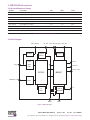
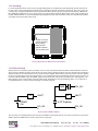
2.4 Block Diagram
ANT_SUPPLY
RF Block
RF_3V3
DIG_1V8/+1V8_OUT
Regulator
DIG_3V3
Regulator
& Reset
Control
Front
RF_IN
End
Emulation
Filter
Comms & I/O
RF25IC
BB25IC
TRIM/EXT_CLK
Clock
IF
RTC &
Filter
EEPROM
NPOR
I2C
VBATT
Figure 1 Block Diagram
SG172 Wi125 User Manual
Page 8 of 50
Rev: 03
Date: 10/20/11
© Copyright 2011 The Connor-Winfield Corp. All Rights Reserved Specifications subject to change without notice
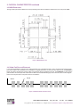
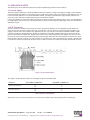
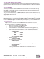
3. PHYSICAL CHARACTERISTICS
The Wi125 is a multi-chip module (MCM) built on an FR4 fiberglass PCB. All digital and power connections to the MCM are via
castellations on the 25 x 27 mm PCB. The RF connection is via castellations or an RF connector. The general arrangement of
the Wi125 is shown in the diagram below. Dimensions are in mm (inches/1000).
.
O: . - HIROSE
H.FL CONNECTOR
PART NO: H.FL-R-SMT
Figure 2 Wi125 Form and Size
3.1Physical Interface Details
The interface to the Wi125 is via 1mm castellation on a 2mm pitch. There are 42 connections in all. There is also an RF connector for connecting to the GPS antenna. The details of the interface connections are given below.
Pin
1
2
3
4
5
6
7
8
9
10
11
12
13
14
15
16
17
18
19
20
21
Function
Pin
Function
TX [0]
RX [0]
TX [2]
RX [2]/EV2_IN
TX [1]
RX [1]
EXT_CLK LED_RED
LED_GRN
NRESET
BOOTSEL
TRIM
TDO
TDI
NTRST
NPOR
RFV_OUT
RF_GND
RF_3V3
TCK
JTAGSEL/RTCK
22
23
24
25
26
27
28
29
30
31
32
33
34
35
36
37
38
39
40
41
42
TMS
RF_GND
RF_IN
RF_GND
ANT_SUPPLY
VBATT
N2WCK
N2WDA
USBP
USBN
FREQ_OUT 3
+1V8_OUT
DIG_1V8
DIG_GND
DIG_3V3
EVENT_IN
1PPS
GPIO [0]/PWM_OUT
GPIO [1]/TIME_SYNC
GPIO [2]/NEXT_INT
GPIO [3]/FREQ_IN
Note: 3. Frequency Output is available on pin 32 (FREQ_OUT) with custom software only.
Table 4 Wi125 Signal List
SG172 Wi125 User Manual
Page 9 of 50
© Copyright 2011 The Connor-Winfield Corp.
Rev: 03
Date: 10/20/11
All Rights Reserved Specifications subject to change without notice
3. PHYSICAL CHARACTERISTICS continued
3.2 MCM Dimensions
The figure below provides the dimensions of the positioning of the Wi125 castellations. Dimensions are in mm (inches/1000).
Figure 3 MCM Dimensions
3.3 Solder Pad Size and Placement
It is recommended that the footprint of the solder pad under each castellation be 2mm x 1mm, centered on the nominal center
point of the radius of the castellation. The castellations are gold plated and so are lead free. Note that if the RF_IN connector is
being used, there should not be a pad or solder resist under the RF_IN castellation. If the RF_IN castellation is to be used, the
pad should be shortened by 0.5mm underneath the Wi125 and standard RF design practices must be observed. The diagram
below shows the placement of the pads under the castellations.
PIN 22
RF_IN
Figure 4 Solder Pad Size and Placement
SG172 Wi125 User Manual
Page 10 of 50
Rev: 03
Date: 10/20/11
© Copyright 2011 The Connor-Winfield Corp. All Rights Reserved Specifications subject to change without notice
4. SIGNAL DESCRIPTION
The signals on the Wi125 are described in the table below. All Test, Control and I/O ports are CMOS 3.3V compatible unless
specified otherwise.
4.1Power Signals
RF_3V3
Type: Power
Direction: Input
Pin: 19
The RF supply input. This 3.3V ± 10% input supplies the 3.0V LDO regulator in the RF
section of the Wi125. It is important that this supply is well filtered with no more that 50mV
peak to peak noise with respect to RF_GND.
RF_GND
Type: Power
The RF input ground connect to common ground. This is the return path for the RF_3V3
supply and the ground for the antenna feed. The RF_GND must be tied to the DIG_GND
externally to the Wi125.
RFV_OUT
Type: Power
Direction: Input/Output
Direction: Output
Pins: 18, 23, 25
Pin: 17
The output from the LDO regulator (3.0V) that is powered by the RF_3V3 signal. This
supplies the power to the RF subsystem of the Wi125. This may also be used to power
external RF components but care must be taken not to inject noise onto this signal. No more
than an additional 30mA may be taken from this signal by external circuitry.
ANT_SUPPLY
Type: Power
The antenna supply voltage. This can be used to supply power to the RF_IN signal, for use
by an active antenna. The maximum voltage should not exceed ±15V and the current should
be limited to 50mA to prevent damage to the Wi125.
DIG_3V3
Type: Power
DIG_1V8
+1V8_OUT
DIG_GND
Direction: Input
Direction: Input
Pin: 26
Pin: 36
The digital supply input. This 3.3V ± 10% input supplies the I/O ring of the BB25IC chip and
the LDO regulator in the digital section of the Wi125. It is important that this supply is well
filtered with no more that 50mV peak to peak noise with respect to DIG_GND.
Type: Power
Direction: Input
Pin: 34
The 1.8V ± 5% digital core supply for the BB25IC. This is normally connected directly to the
+1V8_OUT signal. However, if an external 1.8V ± 5% is available, a lower overall system
power consumption may be achieved by using an external supply.
Type: Power
Direction: Output
Pin: 33
The 1.8V output from the LDO regulator that is powered by the DIG_3V3 signal. Normally,
this is connected to the DIG_1V8 signal. This loops back the regulated 1.8V to run the
processor core. If not connected the core will not run. This may also be used to power
external logic but care must be taken not to inject noise onto this signal. No more than an
additional 50mA may be taken from this signal by external logic.
Type: Power
Direction: Input/Output
Pin: 35
The digital ground. This is the return path for the DIG_3V3 supply and the ground reference
for all the digital I/O. The DIG_GND must be tied to the RF_GND externally to the Wi125.
VBATT
Type: Power
The battery backup supply. The Wi125 has an on board Real Time Clock (RTC). This is
powered from the VBATT signal. A supply of typically 3V (greater than 2.5V and less than
DIG_3V3) should be applied to this signal. This signal can be left floating if not required. The
input has a blocking diode and so rechargeable batteries need an external charging
circuit. Typically, a 1K resister in series with this signal and the external battery will provide
an easy method of measuring the current consumption from VBATT during test.
SG172 Wi125 User Manual
Page 11 of 50
© Copyright 2011 The Connor-Winfield Corp.
Direction: Input/Output
Rev: 03
Date: 10/20/11
All Rights Reserved Specifications subject to change without notice
Pin: 27
4. SIGNAL DESCRIPTION continued
4.2 RF Signals
RF_IN
Type: RF
Direction: Input
Pin: 24
The RF input signal attaches to the GPS antenna. Standard RF design rules must be
used when tracking to this signal. This signal has an RF blocked connection to the
ANT_SUPPLY signal. This is the same signal presented on the RF connector on the Wi125. Only one antenna connection should be made. If the RF connector is to be used, then there
should be no connection, even an unconnected pad, to this castellation.
TRIM
Type: RF
This signal trims the output frequency of the VCTCXO. This signal is normally left open.
When floating, this signal is biased to the control voltage of the VCTCXO. Any noise injected
into this signal will severely compromise the performance of the Wi125. This signal should
only be used in conjunction with specific application notes.
EXT_CLK
Type: RF
Direction: Input
Direction: Input
Pin: 12
Pin: 7
This input is the external clock input. This signal is to be used only in special builds of the
Wi125 that are not fitted with an internal VCTCXO. For the normal build, containing the
VCTCXO, do not connect this input. The external clock is a 20 MHz clipped
sinewave input with an amplitude between 1V and 3V peak to peak. The return path for this signal is RF_GND.
4.3 Emulation/Test Signals
TDI
TDO
TCK
TMS
Type: Test
Direction: Input
Pin: 14
The Test Data In signal is the standard JTAG test data input.
The signal return path is DIG_GND.
Type: Test
Direction: Output
Pin: 13
The Test Data Out signal is the standard JTAG test data output.
The signal return path is DIG_GND.
Type: Test
Direction: Input
Pin: 20
The Test Clock signal is the standard JTAG test clock input.
The signal return path is DIG_GND.
Type: Test
Direction: Input
Pin: 22
The Test Mode Select signal is the standard JTAG test mode input.
The signal return path is DIG_GND.
JTAGSEL/RTCK
Type: Test
This is a dual function signal. When the NPOR signal is asserted (low), this signal is an input
and selects the function of the JTAG interface. When high, JTAG emulation into the embedded
ARM9 processor is selected. When low, the BB25IC chip boundary scan mode is selected.
The value on this signal is latched when NPOR de-asserts (goes high). When NPOR is de
asserted (high) and the JTAG emulation mode has been latched, this signal provides the
return clock to the ARM Multi-ICE. Because the ARM9 functions off a single clock domain,
the TCK has to be internally synchronized in the ARM9. This can cause a variable length delay
in the validity of the TDO signal. The RTCK is a synchronized version of the TCK signal. The
Multi-ICE uses the RTCK output signal to indicate when the TDO signal is valid. The signal
return path is DIG_GND. Pull it to VCC (DIG_3V3) through a 1K resistor for normal operation.
NTRST
Type: Test
Direction: Input/Output
Direction: Input
Pin: 21
Pin: 15
The Test Reset signal. This is the active low JTAG test reset signal. The signal return path is
DIG_GND. Pull it to ground through a 1K resistor for normal operation.
SG172 Wi125 User Manual
Page 12 of 50
Rev: 03
Date: 10/20/11
© Copyright 2011 The Connor-Winfield Corp. All Rights Reserved Specifications subject to change without notice
4. SIGNAL DESCRIPTION continued
4.4 Control Signals
NPOR
Type: ControlDirection: Input/Output
Pin: 16
The Power On Reset signal. This active low, open collector signal is the master reset for the
Wi125. This should be driven with an open collector reset circuit for a minimum of 100ms. An
external pull-up is not required if the 100K internal pull-up is sufficient. The Wi125 can be
held in reset by asserting this signal. The signal can be used to reset external circuitry, but
care must be taken to ensure no DC current is drawn from this signal as the internal pull-up
resistor value is 100K.
NRESET
Type: ControlDirection: Input/Output
The system reset signal. This active low, open collector signal is generated by the BB25IC
chip in response to the assertion of the NPOR. It may also be driven to reset the ARM9
processor in the BB25IC without completely re-initializing the chip.
BOOTSEL
Type: ControlDirection: Input
Pin: 10
Pin: 11
The boot select signal. The BB25IC has four boot up modes, but only two are supported by
the Wi125. This signal is sampled when the NPOR is de-asserted. If the BOOTSEL signal is
high or left floating, then the Wi125 boots from its on-chip FLASH memory. If the BOOTSEL
signal is pulled low, the Wi125 boots from its on-chip ROM.
4.5 I/O Signals
TX [0]
Type: I/O
Direction: Output
The transmit signal for UART 1 is a standard UART output signal.
The signal return path is DIG_GND.
TX [1]
Type: I/O
The transmit signal for UART 2 is a standard UART output signal.
The signal return path is DIG_GND.
TX [2]
Type: I/O
The transmit signal for UART 3 is a standard UART output signal.
The signal return path is DIG_GND.
RX [0]
Type: I/O
RX [1]
RX [2]/EV2_IN
Pin: 1
Direction: Output
Direction: Output
Direction: Input
Pin: 5
Pin: 3
Pin: 2
The receive signal for UART 1 is a standard UART input signal.
The signal return path is DIG_GND. 6
Type: I/O
Direction: Input
Pin: 6
The receive signal for UART 2 is a standard UART input signal.
The signal return path is DIG_GND. 6
Type: I/O
Direction: Input
Pin: 4
This is a dual mode signal. Normally, this is the receive signal for UART 3, a standard UART
receive signal. Under software control, it can also be used as general purpose I/O or to
detect events. It can be used to detect the timing of the leading edge of the start bit of the
incoming data stream. The signal return path is DIG_GND. 6
FREQ_OUT
Type: I/O
Optional frequency output signal. It is NOT the same signal as Pin 39. This signal is turned off
by default. This is a complex signal which under software can provide any of either an NCO
generated output frequency, a PWM signal, a GPS aligned EPOCH pulse or general purpose
I/O signal. The signal return path is DIG_GND.
1PPS
Type: I/O
SG172 Wi125 User Manual
Direction: Input/Output
Direction: Input/Output
Pin: 32
Pin: 38
The 1 pulse per second signal is normally a 1 pulse aligned with GPS time, but can
under software control also provide general purpose I/O or an additional even input. The
pulse width of the 1PPS is software selectable with a default of 100µs. The signal return path
is DIG_GND.
Page 13 of 50
© Copyright 2011 The Connor-Winfield Corp.
Rev: 03
Date: 10/20/11
All Rights Reserved Specifications subject to change without notice
4. SIGNAL DESCRIPTION continued
4.5 I/O Signals continued
EVENT_IN
Type: I/O
Direction: Input/Output
Pin: 37
The Event Input Signal with internal connection to Pin 39 (GPIO[1] / Time Sync) allows
phase measurement of the Frequency Output. The signal return path is DIG_GND.
N2WCK
Type: I/O
N2WDA
USBP
USBN
Direction: Input/Output
Pin: 28
The NavSync 2 Wire Clock signal is the open collector I2C compatible clock signal for
the 2 wire serial interface. The signal return path is DIG_GND. 4
Type: I/O
Direction: Input/Output
Pin: 29
The NavSync 2 Wire Data signal is the open collector I C compatible data signal for the
2 wire serial interface. The signal return path is DIG_GND. 4
2
Type: I/O
Direction: Input/Output
The positive USB signal. The signal return path is DIG_GND.
Type: I/O
Pin: 30
5
Direction: Input/Output
Pin: 31
The negative USB signal. The signal return path is DIG_GND. 5
LED_RED
Type: I/O
This is a dual function signal. Normally this signal is used to drive a red LED. Standard
software builds use this signal to indicate GPS status. In special software builds, this signal
can be used as GPIO. This signal has a 3.3V CMOS drive. A series limiting resistor is
required to limit output current to ±5mA (typically 270 ohms). The signal return path is DIG_GND.
LED_GRN
Type: I/O
GPIO[0]/PWM
GPIO[1]/TIME_SYNC
GPIO[2]/NEXT_INT
GPIO[3]/FREQ_IN
Direction: Output
Direction: Output
Pin: 8
Pin: 9
This is a dual function signal. Normally this signal is used to drive a green LED. Standard
software builds use this signal to indicate GPS status. In special software builds, this signal
can be used as GPIO. This signal has a 3.3V CMOS drive. A series limiting resistor is
required to limit output current to ±5mA (typically 270 ohms). The signal return path is DIG_GND.
Type: I/O
Direction: Input/Output
Pin: 39
Normally the GPIO[0]/PWM output provides a Frequency Output that defaults to 10 MHz, and is
user configurable from 10 Hz to 30 MHz signal. The output is enabled on power-up and is
steered by the GPS solution. Custom software versions can also configure this pin for
general I/O, PWM or EPOCH output. The signal return path is DIG_GND.
Type: I/O
Direction: Input/Output
Pin: 40
The GPIO[1]/TIME_SYNC pin provides a synchronization pulse generated by the onboard
RTC. Custom software versions can also configure this pin for general purpose I/O, or an
additional PPS output. The signal return path is DIG_GND.
Type: I/O
Direction: Input/Output
Pin: 41
The GPIO[2]/NEXT_INT output provides an active high status indicator for the Frequency
Output available on pin 39 (GPIO[0]/PWM). Custom software versions can also configure this
pin for general purpose I/O. The signal return path is DIG_GND.
Type: I/O
Direction: Input/Output
Pin: 42
The GPIO[3]/FREQ_IN output provides an active high status 3D fix indicator. This indicator
can also be used to determine the validity of the pin 38 (1PPS) output. The signal return path is DIG_GND.
Notes
4. Accessible with custom software only.
5. USB is not supported in the current software build. Leave these two pins unconnected.
6. After NPOR is de-asserted, no serial data should be sent for 3 seconds while the serial ports are initialized.
SG172 Wi125 User Manual
Page 14 of 50
Rev: 03
Date: 10/20/11
© Copyright 2011 The Connor-Winfield Corp. All Rights Reserved Specifications subject to change without notice
5. FEATURES
5.1Power on Reset
The power on reset for the Wi125 is generated on-board by the regulator in the RF section from the RF_3V3 signal. The
RF_3V3 signal must be applied to the Wi125 at the same time as the DIG_3V3, if the on-board power on reset is to be used. If
an external source of reset is to be applied to the NPOR signal after both the RF_3V3 and the DIG_3V3 signals are valid, this
restriction does not apply.
5.2 Time Transfer
In order to aid time transfer between fixes during which the Wi125 has been unable to maintain an accurate perception of time
(eg. In deep sleep or powered down states), the on-board RTC can be set to provide a signal derived from the 32.768Hz crystal.
5.3 Wi125 Embedded Identification
The hardware version number is hard coded onto the Wi125; firmware also contains a version number allowing for easy identification of the hardware and software version in embedded applications.
5.4 Stationary Timing Receiver
The Wi125 operates in a survey and position hold mode which allows increased accuracy for timing applications. The Wi125’s
default dynamics setting is 1 and changes to 0 after a 10-minute position survey is completed. Refer to Section 8.3.6 for more
details on the dynamics setting. During operation, the receiver antenna must remain stationary.
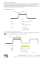
5.5 Frequency Output and 1PPS Phase Alignment
The Wi125 maintains phase alignment between the Frequency Output (up to 10 MHz) and 1pps allowing the Frequency Output
to be used as a time reference as well as a frequency reference. After an initial GPS fix, the phase alignment is maintained during holdover, when the GPS fix is lost. During recovery from holdover, when the GPS fix regained, the Frequency Output and
1PPS walk back to the GPS solution position at a maximum rate of 100 ns/s while maintaining phase alignment between the
two outputs.
SG172 Wi125 User Manual
Page 15 of 50
© Copyright 2011 The Connor-Winfield Corp.
Rev: 03
Date: 10/20/11
All Rights Reserved Specifications subject to change without notice
6. OPERATING MODES
6.1 Stand Alone Operation
For stand alone operation the receiver will perform cold starts with no prior knowledge of position or GPS satellite data such as
almanacs and ephemeris provided the antenna has a clear view of the sky to provide signal strengths of 35dB or higher. The
receiver should be allowed to track satellites for a minimum period of 15 minutes to ensure all almanac information has been
received. The GPS data is stored in the EEPROM memory fitted to the Wi125. Once the receiver has been initialized and has
current almanac and ephemeris data it may then be taken indoors for test with low level signals.
Hot starts (current ephemeris data held in EEPROM) can be performed with low level signals (indoors).
6.2 Network Assist Operation
For network assist operation the NavSync Network Assistance Base Station must be connected to an external antenna and be
tracking all satellites in view. The network assistance data connection is provided by an RS232 link between port 3 on the network assistance base station and port 3 on the Wi125.
With the network assistance base station connected the development system can be started in indoor or outdoor environments.
For more information on the Network Assistance data format please refer to section 8.4.
7. POWER MANAGEMENT
The Wi125 GPS receiver is a low power module consuming less than 0.6W typically for a 1Hz update of position. The receiver
contains software to dynamically reduce power consumption wherever possible. Where channels and taps are not needed they
are switched off. When the processor is not required it is put into a halt until interrupt state and the chips clock system is geared
down to reduce power consumption. All of these things are performed automatically without any user configuration. If further
power saving is required the receiver can be reprogrammed with smaller GPS configurations thereby permanently switching off
portions of the GPS hardware and allowing the processor speed to be reduced, thereby saving power.
7.1 Coma Mode
For powered battery application, which needs to reduce the power consumption, it is possible to switch the receiver into Coma
mode. This configures the RF front end into sleep mode, switches off internal peripherals and places the processor in a sleep
state waiting for an interrupt.
Coma mode is initiated through the COMA serial command, details of which can be found in section 8.3.7.
Care must be taken in the implementation of the Wi125 to ensure power consumption is minimized. All input pins without
bias resistors have potential to float mid rail and consume power during coma mode. Three GPIO pins default as inputs and do
not have bias resistors. GPIO [1]/TIME_SYNC can be factory programmed to provide either an additional PPS output or a time
synchronization input to the GPS engine. GPIO [2]/NEXT_INT can provide an interrupt event from an active low external input.
GPIO [3]/FREQ_IN provide a frequency counter input. Care must be taken to ensure that the pins have external bias resistors
off board to ensure they are not left floating. It is recommended that all unterminated test, Control and I/O ports are pulled high
or low as appropriate (making note of the active state of some ports e.g. BSEL), with typically 100k ohms.
SG172 Wi125 User Manual
Page 16 of 50
Rev: 03
Date: 10/20/11
© Copyright 2011 The Connor-Winfield Corp. All Rights Reserved Specifications subject to change without notice
8. COMMUNICATION PROTOCOLS
Full descriptions of the communications protocols used by the Wi125 can be found in section 8.2 and 8.3.
8.1Port Configuration
There are three serial ports available on the Wi125. They are three UARTs of the Wi125 receiver.
These are configured as follows:
Port
Baud Rate
Function
1
38400
NMEA
2
38400
Debug
3
38400
Network Assistance
Table 6 Port Configurations
All ports are configured as 8 bits, no parity, with no handshaking.
8.2 Output Format
There are two types of messages that can be output from the Wi125 receiver, these are split into NMEA sentences and Debug
messages. Both types of outputs are ASCII strings.
8.2.1 NMEA Messages
There are two main types of sentence, ‘Approved’ and ‘Proprietary’. All sentences start with $ delimited with commas and ending with <CR><LF>. Approved sentences are recognized by the first 5 characters after the $, which define both the kind of talker
providing the information (2 characters, GP in the case of a GPS), and the type of information (3 characters). Proprietary sentences are indicated by a P following the $, as the first of the 5 characters, the next 3 indicating the manufacturer (from a listing
of mnemonic codes), and the 5th character being selected by that manufacturer for the particular sentence structure. Proprietary sentences must conform to the general NMEA structures, but are otherwise undefined outside of the Manufacturers own
documentation.
The following Approved messages are available from the Wi125 receiver:
GPGLL - Geographic Position - Latitude longitude
GPGGA - Global Positioning System Fix Data
GPGSA - GNSS DOP and Active Satellites
GPGSV - GNSS Satellites in View
GPRMC - Minimum required sentence
GPVTG - Velocity and track over ground
GPZDA - Date and time
POLYT - Navsync Proprietary time of day message
POLYP - Navsync Proprietary status message
POLYS - Navsync Proprietary satellite status message (GPGGA + GPGSV)
POLYI - Navsync Proprietary net assist information message
Approved NMEA messages
8.2.1.1 GPGLL - Geographic position, Lat/Lon
Latitude and longitude, with time of position fix and status.
$GPGLL, Latitude, N, Longitude ,E, hhmmss.sss, Status, Mode*cs
Name
Description
$GPGLL
NMEA sentence header (Position Data)
Latitude
User datum latitude degrees, minutes, decimal minutes format (ddmm.mmmmmm)
N
Hemisphere ‘N’= North, or ‘S’ = South
Longitude
User datum longitude degrees, minutes, decimal minutes format (dddmm.mmmmmm)
E
Longitude Direction ‘E’= East, or ‘W’ = West
hhmmss.sss
UTC Time in hours, minutes, seconds and decimal seconds format.
Status
StatusV=navigation receiver warning, A=data valid
Mode
Mode indicator:A=Valid, Autonomous, D=Valid, Differential, E=Invalid, Estimated, N=Invalid, Not valid
Cs Message checksum in hexadecimal
SG172 Wi125 User Manual
Page 17 of 50
© Copyright 2011 The Connor-Winfield Corp.
Rev: 03
Date: 10/20/11
All Rights Reserved Specifications subject to change without notice
8. Communication Protocols continued
8.2.1.2 GPGGA - GPS fix data
Time and position, together with GPS fixing related data.
$GPGGA, hhmmss.sss, Latitude, N, Longitude , E, FS, NoSV, HDOP , Altref , M, msl , M, DiffAge , DiffStation*cs
Name
Description
$GPGGA
NMEA sentence header (Position Data)
hhmmss.sss
UTC Time in hours, minutes, seconds and decimal seconds format.
Latitude
User datum latitude degrees, minutes, decimal minutes format (ddmm.mmmmmm)
N
Hemisphere ‘N’= North, or ‘S’ = South
Longitude
User datum longitude degrees, minutes, decimal minutes format (dddmm.mmmmmm)
E
Longitude Direction: ‘E’= East, ‘W’ = West
FS
Fix Status:
0 No fix
1 Standard GPS
2 Differential GPS
NoSv
Number of satellites used in the position solution
HDOP
2-D Horizontal Dilution of Precision (0.00 to 99.99)
AltRef
Altitude (meters) above user datum ellipsoid
M Units of height (meters)
msl Mean Sea Level
M Units of Mean Sea Level (meters)
DiffAge
Age of differential correction
DiffStation
Differential base station ID
cs Message checksum in hexadecimal
8.2.1.3 GPGSA - GPS DOP and Active satellites
GPS receiver operating mode, satellites used for navigation, and DOP values.
$GPGSA,Smode,FS,sv,sv,sv,sv,,,,,,,,PDOP,HDOP,VDOP*cs
Name
Description
$GPGSA
NMEA sentence header (Satellite Data)
Smode
A= Automatic switching 2D/3D M=Manually fixed 2D/3D
FS
Fix Status:
1 No fix
2 2D GPS Fix 3 3D GPS Fix
sv Satellites in use, null for unused fields (12 available fields)
PDOP
3-D Position Dilution of Precision (0.00 to 99.99)
HDOP
2-D Horizontal Dilution of Precision (0.00 to 99.99)
VDOP
Vertical Dilution of Precision (0.00 to 99.99)
cs Message checksum in hexadecimal
SG172 Wi125 User Manual
Page 18 of 50
Rev: 03
Date: 10/20/11
© Copyright 2011 The Connor-Winfield Corp. All Rights Reserved Specifications subject to change without notice
8. Communication Protocols continued
8.2.1.4 GPGSV - GPS Satellites in View
The number of satellites in view, together with each PRN, elevation and azimuth, and C/No value. Up to four satellite
details are transmitted in one message, with up to three messages used as indicated in the first field.
$GPGSV, NoMsg, MsgNo, NoSv{,sv,elv,az,cno}{,sv,elv,az,cno….}*cs
Note: {} designate optional sections that appear only if there is satellite data.
Name
Description
$GPGSV
NMEA sentence header (Satellite Data)
NoMsg
Total number of GPGSV messages being output
MsgNo
Number of this messages
NoSv
Number of satellites in view
sv Satellites ID
elv Satellite elevation angle (degrees)
az Satellite azimuth angle (degrees)
cno Satellite signal/Noise ration (dB/Hz)
cs Message checksum in hexadecimal
8.2.1.5 GPRMC - Recommended Minimum data
The ‘Recommended Minimum’ sentence is defined by NMEA for GPS/Transit system data.
$GPRMC,hhmmss.sss,status,latitude,N,Hemisphere,longitude,E,spd,cmg,ddmmyy,mv,mvd,Mode*cs
Name
Description
$GPRMC
NMEA sentence header (Recommended Minimum Sentence)
hhmmss.sss
UTC Time in hours, minutes, seconds.
status
Status:V=navigation receiver warning, A=data valid
Latitude
User datum latitude degrees, minutes, decimal minutes format (ddmm.mmmmmm)
N
Hemisphere: ‘N’= North, or ‘S’ = South
Longitude
User datum longitude degrees, minutes, decimal minutes format (dddmm.mmmmmm)
E
Longitude Direction: ‘E’= East, ‘W’ = West
spd
Speed over ground (knots).
cmg
Course made good
ddmmyy
Date in Day, Month Year format
mv Magnetic variation
mvd
Magnetic variation direction
Mode
Mode Indicator: D = Valid, Differential, A = Valid, Autonomous, E = Invalid, Estimated, N = Invalid, Not Valid
cs Message checksum in hexadecimal
SG172 Wi125 User Manual
Page 19 of 50
© Copyright 2011 The Connor-Winfield Corp.
Rev: 03
Date: 10/20/11
All Rights Reserved Specifications subject to change without notice
8. Communication Protocols continued
8.2.1.6 GPVTG - Course over ground and Ground speed.
Velocity is given as Course over Ground (COG) and Ground Speed
$GPVTG,cogt,T,cogm ,M ,knots,N,kph,K,Mode*cs
Name
Description
$GPVTG
NMEA sentence header (Speed and heading)
cogt
Course over ground (true)
T
True - fixed field
cogm
Course over ground (magnetic)
M Magnetic - fixed field
knots
Speed over ground (knots)
N
Knots - fixed field
kph Speed over ground (kph)
K
Kilometers per hour – fixed field
Mode
Mode Indicator:D = Valid, Differential, A = Valid, Autonomous, E = Invalid, Estimated, N = Invalid, Not Valid
cs Message checksum in hexadecimal
8.2.1.7 GPZDA - UTC Time and Date
This message transfers UTC Time and Date. Since the latency of preparing and transferring the message is variable,
and the time does not refer to a particular position fix, the seconds’ precision is reduced to 2 decimal places.
$GPZDA,hhmmss.sss,dd,mm,yyyy,Int,Unsigned*cs
Name
Description
$GPZDA
NMEA sentence header (Time and Date)
hhmmss.sss
UTC Time in hours, minutes, seconds.
dd UTC day
mm UTC month
yyyy
UTC year
Int Unsigned
Local zone hours
Int Unsigned
Local zone minutes
kph Speed over ground (kph)
K
Kilometers per hour – fixed field
cs Message checksum in hexadecimal
Proprietary NMEA Messages
8.2.1.8 POLYT - Time of Day
$POLYT,hhmmss.sss,ddmmyy, UTC_TOW ,week, GPS_TOW ,Clk_B , Clk_D ,PG,LocalTTag,BAcc,TAcc,BLANK*cs
Name
Description
$POLYT
NavSync Proprietary NMEA sentence header (Position Data)
hhmmss.sss
UTC Time in hours, minutes, seconds and decimal seconds format.
ddmmyy
Date in day, month, year format.
UTC_TOW
UTC Time of Week (seconds with microseconds resolution)
week
GPS week number (continues beyond 1023)
GPS_TOW
GPS Time of Week (seconds with microseconds resolution)
Clk_B
Receiver clock Bias (nanoseconds)
Clk_D
Receiver clock Drift (nanoseconds/second)
PG 1PPS Granularity (nanoseconds)
LocalTTag
Local receiver time-tag since start-up [msec]
BAcc
Bias Accuracy
TAcc
Time Accuracy
cs Message checksum in hexadecimal
SG172 Wi125 User Manual
Page 20 of 50
Rev: 03
Date: 10/20/11
© Copyright 2011 The Connor-Winfield Corp. All Rights Reserved Specifications subject to change without notice
8. Communication Protocols continued
8.2.1.9 POLYP- Position Data
$POLYP,hhmmss.sss,Latitude,N,Longitude,E, AltRef ,FS,Hacc,Vacc, SOG , COG , V_vel,ageC,HDOP,VDOP,PDOP,G
DOP,TDOP,GU,RU,DR*cs
Name
Description
$POLYP
NavSync Proprietary NMEA sentence header (Position Data)
hhmmss.sss
UTC Time in hours, minutes, seconds and decimal seconds format.
Latitude
User datum latitude degrees, minutes, decimal minutes format (ddmm.mmmmmm)
N
Hemisphere: ‘N’= North, ‘S’ = South
Longitude
User datum longitude degrees, minutes, decimal minutes format (dddmm.mmmmmm)
E
Longitude Direction: ‘E’= East, ‘W’ = West
AltRef
Altitude (meters) above user datum ellipsoid.
FS
Fix Status:
NF = No Fix DR = Predictive Dead Reckoning solution DA = Predictive Dead Reckoning solution with DR aiding
G1 = Partial GPS solution with DR aiding
G2 = Stand alone 2D solution
G3 = Stand alone 3D solution
D1 = Partial Differential GPS solution with DR aiding
D2 = Differential 2D solution D3 = Differential 3D solution
Hacc
Horizontal (2 sigma) accuracy estimates (0 to 99999 meters)
Vacc
Vertical (2 sigma) accuracy estimates (0 to 99999 meters)
SOG
Speed Over Ground (knots) (0.000 to 999.999 knots)
COG
Course Over Ground (true) in degrees (0.00 to 359.99 degrees)
V_vel
Vertical (positive Up) velocity (m/s) (0.000 to 999.999 m/s)
ageC
Age of most recent DGPS Corrections applied (seconds).(00.00 to 99.99 = none available)
HDOP
2-D Horizontal Dilution of Precision (00.00 to 99.99)
VDOP
Vertical Dilution of Precision (00.00 to 99.99).
PDOP
3-D Position Dilution of Precision (00.00 to 99.99)
TDOP
Time Dilution of Precision (00.00 to 99.99)
GU Number of GPS satellites used in the navigation solution
RU Number of GLONASS satellites used in the navigation solution
DR
Dead Reckoning aiding status bits (in ASCII Hex)
bit 0
Altitude Position Aiding applied
bit 1
Vertical Velocity Aiding applied
bit 2
(GPS-GLONASS) time difference aiding applied
bit 3
External Distance travelled input used
bit 4
External Speed input used
bit 5
External Track input used
bit 6
External Delta -Track input used
bit 7,8
Reserved for future use
cs Message checksum in hexadecimal
SG172 Wi125 User Manual
Page 21 of 50
© Copyright 2011 The Connor-Winfield Corp.
Rev: 03
Date: 10/20/11
All Rights Reserved Specifications subject to change without notice
8. Communication Protocols continued
8.2.1.10 POLYS - Satellite Status
$POLYS,GT{,ID,s,AZM,EL,SN,LK}{,ID,s,AZM,EL,SN,LK}{,ID,s,AZM,EL,SN,LK}{,ID,s,AZM,EL,SN,
LK}{,ID,s,AZM,EL,SN,LK}{,ID,s,AZM,EL,SN,LK}{,ID,s,AZM,EL,SN,LK}{,ID,s,AZM,EL,SN,LK}{,ID,
s,AZM,EL,SN,LK}{,ID,s,AZM,EL,SN,LK}{,ID,s,AZM,EL,SN,LK}{,ID,s,AZM,EL,SN,LK}*cs
Note: {} designate optional sections that appear only if there is satellite data
Name
Description
$POLYS
NavSync Proprietary NMEA sentence header (Satellite Data)
GT Number of GPS satellites tracked
ID Satellite PRN number (1-32)
s
Satellite status
- = not used U = used in solution
e = available for use, but no ephemeris
AZM
Satellite azimuth angle (range 000 - 359 degrees)
EL Satellite elevation angle (range 00 - 90 degrees)
SN Signal to noise ratio in (range 0 - 55 dB/Hz)
LK Satellite carrier lock count (range 0 - 255 seconds)
0 = code lock only
255 = lock for 255 or more seconds
cs Message checksum in hexadecimal
8.2.1.11 POLYI, Additional Information Message
$POLYI,JN,jammer,EXT{,efields},INT{,ifields},BLANK*cs
Note: More than one {efield} or {ifield} may be present, each separated by commas.
Name
Description
$POLYI
NavSync Proprietary NMEA sentence header (Additional Information)
JN Fixed descriptor field
jammer
Detected Jammer to Noise Ratio [dB/Hz]
EXT
Fixed descriptor field, indicates the use of externally provided ancillary measurements e.g.
received from Network Assistance. All comma separated fields following, up to the INT field
descriptor, are externally provided measurements
efields
DIFF = Differential Inputs
TSYNC = Time synchronization
CLKB = Clock Bias
FREQ = Frequency (of reference oscillator)
HPOS = Horizontal position VPOS = Vertical Position (altitude)
VVEL = Vertical Velocity
DIST = Distance Moved
SPEED = Current Speed
TRACK = Current track
DTRACK = Delta track (change in direction)
INT Fixed descriptor field, indicates the use of internally provided ancillary measurements e.g.
retrieved from non volatile memory. All comma separated fields following, are internally
provided measurements
ifields
TSYNC = Time synchronization
CLKB = Clock Bias
FREQ = Frequency (of reference oscillator)
HPOS = Horizontal position VPOS = Vertical Position (altitude)
VVEL = Vertical Velocity
DIST = Distance Moved
SPEED = Current Speed
TRACK = Current track
DTRACK = Delta track (change in direction)
BLANK
Reserved for future use
cs Message checksum in hexadecimal
SG172 Wi125 User Manual
Page 22 of 50
Rev: 03
Date: 10/20/11
© Copyright 2011 The Connor-Winfield Corp. All Rights Reserved Specifications subject to change without notice
8. Communication Protocols continued
8.2.2 Debug Messages
The debug messages were implemented for internal testing purposes, but may be useful for advanced users requiring more
information than is available through the standard NMEA output messages.
The messages were designed to be displayed on a terminal, which recognizes the HOME character (ASCII 11) and clear
screen (ASCII 12). This mode is supported in NS3Kview by switching the NMEA monitor window of NS3Kview to debug mode,
see section 10.3 in NS3Kview User Manual. To display information on a terminal use a VT-100 emulation, this will allow the information to be display static on the screen, rather than being scrolling text.
Each information page can be commanded by sending $x<cr><lf>, where x is the page number. A list of the most commonly
used debug pages is listed by sending $1<cr><lf> as shown below:
Screens 11,52
NV_RAM = 4980
NA_RAM = 3288
Stacks = 3968
dsp_SD = 12240
The above example shows that debug screens 11 and 52 are available. The additional information details the amount of memory used within the systems for Non volatile memory, Network Assistance data, Stacks and DSP data memory.
To display any of the available debug screens simply type $x<cr>, where x is the screen number e.g. $11<cr>
Each of the above information pages is detailed below. The debug information is not limited to the above list and special debug pages may be available depending on the software within the receiver. Any additional pages specific to software versions
are not described in this manual.
8.2.3.1 Navigation and Timing Summary ($11)
Navigation Summary Page 12x32x32x16 Wi125 1.741 May 10 200415:03:41
Time 140533.70 3840 1270 137133.708 1 15 0 -569556.04 -675.87
Geod 52 14 58.28304 N 1 9 21.20855 E 209.19 161.75 s--------------Local 921.146 -15325.118 83.187 0.009 0.007 193.89 0.015
Acc 5 5 1 0 34 101 106 95 95 0.24 0.15 1.70 2.43 2.97
ExtT 0 0.000 0.000 0 0.000000 0.000 0 0.000 0.000
APA 0 0.000 0.000 0.000 VVA 0 0.000 0.000 0.000 dy 2 T0 0
Sigs 1.569 1.235 0.000 0.100 0.003 0.006 EC 0 0 0 JN 0
VarF 0.011 0.007 0.000 0.072 0.002 0.007 S 1 I 1.024 cr 0 ts 0
Reset 0 93 4813 0 QB 022 13 ST 1 SUB_MS SP 10 FF 48.5
SV 11 64 1B8C 15 35 0 4403 228 13 144 -4.041 10 0.033 10 1 -2589
SV 32 64 104A 6 31 0 444 x -9 -0 0.000 00 0.000 00 0 -830
SV 4 64 1B8C 15 46 0 4425 132 50 297 1.764 10 0.023 10 1 3034
SV 5 0 1000 1 0 0 0
x
-9 -0 0.000 00 0.000 00 0 0
SV 6 64 101A 6 30 0 19
x
-9 -0 0.000 00 0.000 00 0 1181
SV 7 64 198C 15 39 0 4653 45 31 242 0.481 10 0.032 10 1 -999
SV 20 64 1B8C 15 48 0 5029 184 56 81 -0.853 10 0.022 10 1 830
SV 13 64 1B8C 15 45 0 4317 55 44 202 2.546 10 0.034 10 1 3961
SV 25 64 1B8C 15 37 0 3156 x
-9 -0 0.000 00 0.000 00 0 -543
SV 3 54 101A 6 30 0 33
x
-9 -0 0.000 00 0.000 00 0 2174
SV 1 64 1B8C 15 48 0 4141 208 72 120 0.168 10 0.032 10 1 1171
SV 16 63 101B 6 30 0 273 x
-9 -0 0.000 00 0.000 00 0 1178
THE_END 42 HC 0 0 0 2
EEPROM read -------- -------- -------- -------- -------- -----
0x0000 EEPROM write e--e--e- --e-e--- ---ea--- -------- ---H--- -----
0x0000 SG172 Wi125 User Manual
Page 23 of 50
© Copyright 2011 The Connor-Winfield Corp.
Rev: 03
Date: 10/20/11
All Rights Reserved Specifications subject to change without notice
99
99
99
91
99
99
99
99
99
99
99
99
0
0
4
106
4
106
106
4
4
4
106
106
4
106
6
3945
6
3945
3945
6
6
6
3945
3945
6
3945
2
3
2
6
6
1
1
2
4
5
3
7
8. Communication Protocols continued
Software Configuration and version: channels x taps x FFT points, Software version and date
Time tag information: UTC time in hhmmss.sss format, Software time tag (seconds since switch on), Week number, time of
week, Fix time (number of seconds with 3D fix), No fix time (number of seconds without 3D fix, Clock bias in metres, Clock drift
in metres.
Geod: Latitude, Longitude, Ellipsoidal altitude, Mean sea level altitude
Local: Local grid E,N,U (from initial position), Ground speed, Vertical velocity, Track
Acc: GPS Fix, Fix OK flag, Differential flag, Estimated horizontal accuracy (m), Estimated vertical accuracy (m), Estimated position accuracy (m), Estimated time accuracy (m), Estimated speed accuracy (m/s), Estimated frequency accuracy (m/s), HDOP,
VDOP, PDOP
Ext T: External input data e.g. from network assistance
Altitude Position Aiding (APA): APA required flag, APA used flag, Measurement, Variance, Residual, Residual quality
Sigs: Instantaneous pseudorange residuals, Accumulated pseudorange residuals, Pseudorange edit count, Instantaneous
doppler residuals, Accumulated doppler residuals, Doppler edit count, Instantaneous delta-range residuals, Accumulated deltarange residuals, Delta-range edit count.
Reset: Kalman reset flag, Last reset type, Number of solutions since last Kalman reset, Total number of resets, Number of solutions since last Kalman Q boost, Week number set flag, Time set flag, Sufficient position flag, Skip check flag, Time to first fix,
Time to first fix – ION definition
Satellite Information: Satellite ID, Tracking status (not described), Measurement status, Signal strength (C/No), Mean signal
strength, Lock counter, IODE, Elevation angle, Satellite used in solution flag, Pseudorange residuals, Pseudorange residuals
OK flag, Pseudorange residuals edit flag, Doppler residuals, Doppler residuals OK flag, Doppler residuals edit flag, Delta-range
residuals, Delta-range residuals OK flag, Delta-range residuals edit flag
EEPROM Read & EEPROM Write: Non volatile data usage. The characters shown indicate what data has been read or is written to the EEPROM. a =almanac, e= ephemeris, B=Both (almanac and ephemeris), T=Time, P=Position, H=Height
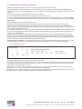
8.2.2.2 RF & AGC data ($52)
DSP_RF_AGC
1
1
18
0
0.0
0.2
DC
offset
0
0
0.0
(%)
AGC & Offset Mode, Current Value
95339 130237 94423 0
0
29.7
40.6
29.5
0.0
0.0
AGC_counters
AGC_counters (%)
AGC: AGC & Offset Mode 1=Auto, 0=Off, Current value of AGC (0-32)
AGC counters: Shows a table of 7 columns, each column indicates the number of times each level has been encountered in the
last integration period. The columns indicate levels –3, -2, -1, 0, +1, +2, +3. For the example shown above only three levels are
being used so all counts are either –1, 0 or +1.
AGC Counters %: Shows the AGC counters as a percentage. For a 3 level system the optimum AGC setting should have approximately 27%in +1 and –1 and 46% in 0, this represent a Gaussian distribution.
DC Offset: Shows the amount of imbalance in the measured signal. Ideally the DC offset should be zero, but will show a slight
DC offset of up to a few percent due to the adjustment resolution in the RF front end.
SG172 Wi125 User Manual
Page 24 of 50
Rev: 03
Date: 10/20/11
© Copyright 2011 The Connor-Winfield Corp. All Rights Reserved Specifications subject to change without notice
8. Communication Protocols continued
8.3 Command Format *
The NavSync Wi125 receiver has a unique set of proprietary commands.
Commands will only be accepted on Port 1.
The commands to and from the unit have the following general formats:
$PRTH<Q|S|R>,<id>,<msg fields>[*<checksum>]<cr><lf>
Where:
< |Q|S|R> is the single ASCII character as follows:
Q: Command, a query command to the Wi125 receiver.
S: Command, requires the Wi125 receiver to set system settings.
R: Response to a Wi125 receiver, response to a $PRTH Query or an acknowledgement of a $PRTH Set.
<id> is a 4 character command identifier.
<msg fields> are the message fields for the message and are all positional. Optional or unknown fields are shown as nulls
(ie adjacent commas). Trailing commas to the end of a message (ie nothing but null message fields) are not required.
*<checksum> An optional checksum byte for checking accuracy defined as follows:
The checksum is displayed as a pair of ASCII characters, (0-9 and A-F inclusive) whose value represents the “HEX” value of
the checksum byte. When used, it always appears as the last field of the sentence and is prefixed by field delimiter “*” (HEX 2A)
instead of “,” and followed by <CR><LF> (HEX 0D 0A). The checksum value is calculated by XOR’ing (exclusive OR’ing also
known as Modulo 2 Sum) the 8 binary data bits of each valid data character in the sentence between the “$” (HEX 24) and “*”
(HEX 2A) characters.
The “$” (HEX 24) and the “*” (HEX 2A) characters are not included in the checksum.
<cr><lf> are the ASCII codes 0Dh and 0Ah (carriage return and line feed) respectively.
Some commands use multiple sentences to transfer data: multiple sentence transfer shall be accomplished by means of 2 fields
within the sentence for which this format is used:
t: Total number of sentences forming the data transfer (minimum value 1)
x: ID number of the current sentence ranging from 1 to t inclusive
Null fields within a command shall be interpreted as “use current value” where appropriate. Null fields must be delimited
by adjacent commas when they exist between two non-null fields. If all trailing fields after a given field are null, further
commas are not required.
*Note: For Wi125-TIM, the commands include:
VERS DYNA ITIM RSET INTM ILLH COMA FRQD IDNO ZONE
For Wi125-NAV, the commands include:
VERS DYNA ITIM RSET INTM ILLH COMA FRQD IDNO ZONE
The accuracy testing of INTM command is not yet implemented. Additional commands, some documented here, can be enabled with custom firmware. Further customization is also available. Please consult the factory for details.
8.3.1 PRTH<Q|R>, VERS: Software Version
Purpose
This message Queries and Responds with the current software version information.
Query Format
$PRTHQ,VERS[*checksum]<cr><lf>
Response /Acknowledge Format
$PRTHR,VERS,Build_Name,Version_Number,Version_Date,Version_Time, Serial_Num, BB_
Releaset*<checksum><cr><lf>
Explanation of Parameters
Build_Name Product name (i.e. Wi125-TIM or Wi125-NAV)
Version_Number
Software version number
Version_DateSoftware build date in Mmm_dd_yyyy format where Mmm is the Three character
abbreviation of the month name\
Version_TimeSoftware build time in hh:mm:ss format
Serial_Num Product serial number is current not implemented and always outputs “Serial_Num”
BB_Release
Baseband version number
SG172 Wi125 User Manual
Page 25 of 50
© Copyright 2011 The Connor-Winfield Corp.
Rev: 03
Date: 10/20/11
All Rights Reserved Specifications subject to change without notice
8. Communication Protocols continued
8.3.2 PRTH<Q|S|R>, DYNA: RECEIVER DYNAMICS
Purpose
This message Sets, Queries and Responds to the receiver host dynamics and hence the maximum receiver tracking
dynamics expected.
The degree of filtering performed by the navigation and timing Kalman filter is dependant on the selected receiver
platform.
Query Format
$PRTHQ,DYNA[*checksum]<cr><lf>
Set Format
$PRTHS,DYNA,platform[*checksum]<cr><lf>
Response / Acknowledge Format
$PRTHR,DYNA,platform*<checksum><cr><lf>
Explanation of Parameters
platform receiver platform (integer, range 0 – 10) 0
= Fixed base station, Timing and Frequency modes etc
1
= Stationary, but unknown position
2
= Man pack / walking
3
= Automotive / Land Vehicle
4
= Marine
5
= Airborne, Low dynamics (<1g) — Limit of Wi125
6
= Airborne, Medium dynamics <2g)
7
= Airborne, High dynamics (<4g)
8
= Airborne, Very High dynamics (<8g)
9
= Drone, Missile dynamics (<16g)
10
= Pure least squares mode (ie semi-infinite dynamics assumed)
Default for Wi125-NAV is 3, maximum is 5. Default for Wi125-TIM is 1 and changes to 0 after 10 minute location survey
completed, maximum is 5.
8.3.3 PRTH<Q|S|R>, ITIM: INITIALIZE TIME AND DATE
Purpose
This message Sets, Queries and Responds to the user initialized time and date. Two input options are available, one
allowing a calendar date and GMT time to be input and the other a GPS week number and seconds of week.
The input date is acted upon regardless and is primarily used to set the GPS week inside the receiver. The time input will
not be used if is set to zero, or if the receiver is currently tracking any satellites and therefore already has a good submillisecond knowledge of time.
If the time input is not used then the Response message returns the values used or assumed instead of those input. The
time RMS accuracy is used to decide how much importance to put on the input values and should be set with care.
Query Format
$PRTHQ,ITIM[*checksum]<cr><lf>
Set Format
Using a GMT time format
$PRTHS,ITIM,timeRMS,GMT,day,month,year,[hours],[minutes],[seconds] [*checksum]<cr><lf>
Using a GPS time format
$PRTHS,ITIM,timeRMS,GPS,gps_week,[gps_time][*checksum]<cr><lf>
Response / Acknowledge Format
$PRTHR,ITIM,timeRMS,GMT,day,month,year,hours,minutes,seconds,GPS, gps_week,gps_time*<checksum><cr><lf>
Explanation of Parameters
time RMS
RMS accuracy of the input time-tag (seconds)
(floating point, range 0 – 999999.0).
day
day of month (integer, range 1 – 31).
month
month of year (integer, range 1 – 12).
year
4 digit year (integer, range 1980 – 2047).
hours
hours of day (integer, range 0 – 23).
minutes
minutes of hour (integer, range 0 – 59).
seconds
seconds of minute (floating point, range 0 – 59.999).
gps_week
GPS week number, including pre GPS roll-over weeks, eg 1037 (integer, range 0 – 32768)
gps_TOW
GPS Time of Week in seconds (floating point, range 0.0 –604800.0).
SG172 Wi125 User Manual
Page 26 of 50
Rev: 03
Date: 10/20/11
© Copyright 2011 The Connor-Winfield Corp. All Rights Reserved Specifications subject to change without notice
8. Communication Protocols continued
8.3.4 PRTH<Q|S|R>, RSET: RE-SET THE RECEIVER
Purpose
This message Sets, Queries and Responds to a receiver re-set command with optional actions such as clearing specific
data groups stored in the Wi125 local EEPROM.
The data areas that can be cleared include satellite almanacs, ephemerides, network assist and receiver configuration
parameters.
Note that “sleep” mode is not currently supported in the Wi125 technology.
This command invokes a 2 second time-out prior to the reset being called.
Query Format
$PRTHQ,RSET[*checksum]<cr><lf>
Set Format
$PRTHS,RSET,{[option],[option],….}[*checksum]<cr><lf>
Response / Acknowledge Format
$PRTHR,RSET,{[option],[option],….}*<checksum><cr><lf>
A response option of NO, indicates that no reset command is currently activated.
Explanation of Parameters
option
A list of character descriptors to indicate which, if any, of the optional actions are to be undertaken prior to the software
re-sets.
”CONFIG” = clear the receiver configuration data stored in EEPROM.
”EPH” = clear the satellite ephemeris data stored in EEPROM.
”ALM” = clear the satellite almanac data stored in EEPROM.
”NA” = clear the network assist data stored in EEPROM.
8.3.5 PRTH<Q|S|R>, INTM: INTERMITTENT OPERATION PARAMETERS
Purpose
This message Queries, Sets and Respond with the Fix Interval, Run Duration, Run Interval, Horizontal and Vertical
Accuracy Masks for intermittent operation. Once the receiver has met the required Horizontal and Vertical Accuracy
Masks it will go to sleep until the next Run Interval. The receiver will also go to sleep if no fix or the accuracy masks have
not been met within the Run Duration.
Query Format
&PRTHQ, INTM [*checksum]<cr><lf>
Set Format
$PRTHS, INTM, Fix_Interval, Run_Duration, Run_Interval, Horizontal_Acc_Mask, Vertical_Acc_Mask[*checksum]<cr><lf>
Response / Acknowledge Format
$PRTHR, INTM*<checksum><cr><lf>
Explanation of Parameters
Fix_Interval
Interval in ms between adjacent fixes
Run_Duration
Maximum time in ms to attempt to obtain fix. Must be greater than Fix_Interval
and is 0 for continuous operation
Run_Interval
Time interval in ms between waking to obtain a fix. Must be greater than Run_Duration
Horizontal_Acc_Mask
Required horizontal accuracy in meters before run completes. Zero disables vertical
accuracy testing.
Vertiacl_Acc_Mask
Required vertical accuracy in meters before run completes.
Zero disables vertical accuracy testing.
SG172 Wi125 User Manual
Page 27 of 50
© Copyright 2011 The Connor-Winfield Corp.
Rev: 03
Date: 10/20/11
All Rights Reserved Specifications subject to change without notice
8. Communication Protocols continued
8.3.6 PRTH<Q|S|R>, ILLH: INITIALIZED LAT, LONG, HEIGHT POSITION
Purpose
This message Sets, Queries and Responds to the initialized geodetic position (latitude, longitude, ellipsoidal height and
antenna height above the reference marker) in the receiver’s current user datum.
The position RMS accuracy is used to decide how much importance to put on the input values and should be set with care.
Query Format
$PRTHQ,ILLH[*checksum]<cr><lf>
Set Format
$PRTHS,ILLH,LatDeg,LatMin,LatSec,LatH,LonDeg,LonMin,LonSec,LonH,EllHt,AntHt,posRMS [*checksum]<cr><lf>
Response / Acknowledge Format
$PRTHR,ILLH,LatDeg,LatMin,LatSec,LatH,LonDeg,LonMin,LonSec,LonH,EllHt,AntHt,posRMS*<checksum><cr><lf>
Explanation of Parameters
LatDeg
Latitude degrees (floating point, range ±90.0)
LatMin
Latitude minutes (floating point, range ±59.999999)
LatSec
Latitude seconds (floating point, range ±59.99999)
LatH
Latitude hemisphere (char ‘N’ or ‘S’)
LonDeg
Longitude degrees (floating point, range ±90.0)
LonMin
Longitude minutes (floating point, range ±59.999999)
LonSec
Longitude seconds (floating point, range ±59.99999)
LonH
Longitude hemisphere (char ‘E’ or ‘W’)
EllHt
Height of the reference marker above the current user datum reference ellipsoid in metres
(floating point, range ±18,000.0)
AntHt
Height of the antenna phase centre above the reference marker height defined by EllHt above in
metres (floating point, range ±18,000.0)
posRMS
RMS accuracy of the input position (metres)
(floating point, range 0 - 999999.0)
Note that since the Degree, Minutes and Seconds fields will accept floating point values then a decimal degree value, or and integer degree, decimal minute
value can be input directly by setting the minutes and seconds fields to zero as appropriate (eg 52.12345678,0,0,N or 52,14.123456,0,N).
8.3.7 PRTH<Q|S|R>, COMA: COMA MODE
Purpose
This message Sets, Queries and Responds Coma mode. Coma mode puts the receiver to sleep for a predetermined
period of time.
Query Format
$PRTHQ,COMA[*checksum]<cr><lf>
Set Format
$PRTHS,COMA,Period[*checksum]<cr><lf>
Response / Acknowledge Format
$PRTHR,COMA,Period*<checksum><cr><lf>
Explanation of Parameters
Period The period in milliseconds that the receiver will sleep.
8.3.8 PRTH<Q|S|R>, FRQD: FREQUENCY OUTPUT SELECT
Purpose
This message Sets, Queries and Responds the Frequency Output. Outputs the requested frequency from the GPIO [0]
port as detailed in section 13.
Query Format
$PRTHQ,FRQD[*checksum]<cr><lf>
Set Format
$PRTHS,FRQD,Frequency[*checksum]<cr><lf>
Response / Acknowledge Format
$PRTHR,FRQD,Frequency*<checksum><cr><lf>
Explanation of Parameters
Frequency The frequency in Megahertz that the receiver will output. Wi125-TIM defaults to 10 MHz, 30 MHz maximum.
Wi125-NAV defaults to 0 MHz (disabled), 20 MHz maximum. e.g. for 10kHz = 0.010
0 = switch digital frequency off.
SG172 Wi125 User Manual
Page 28 of 50
Rev: 03
Date: 10/20/11
© Copyright 2011 The Connor-Winfield Corp. All Rights Reserved Specifications subject to change without notice
8. Communication Protocols continued
8.3.9 PRTH<Q|S|R>, MMSV: MIN & MAX SATELLITES FOR A POSITION SOLUTION
Purpose
This message Sets, Queries and Responds to the minimum and maximum number of satellites the receiver will use for
a position solution. Increasing the minimum number of satellites will improve the accuracy achieved when sufficient
satellites are available, but may reduce the time when a solution can be produced. Reducing the maximum number of
satellites may reduce the accuracy of the position solution, but will decrease the amount of processing power required for
the solution.
Note that setting the Maximum satellites to less than 4 will prevent the receiver from performing a 3D position solution.
Likewise setting the minimum number of satellites greater than 3 will prevent the receiver performing a 2-D, altitude fixed
solution.
The maximum must be greater than or equal to the minimum number of satellites.
Query Format
$PRTHQ,MMSV[*checksum]<cr><lf>
Set Format
$PRTHS,MMSV,[min_NSV],[max_NSV][*checksum]<cr><lf>
Response / Acknowledge Format
$PRTHR,MMSV,min_NSV,max_NSV*<checksum><cr><lf>
Explanation of Parameters
min_NSV
Minimum Satellites used for a position / time solution (integer, range 0-12)
max_NSV Maximum Satellites used for a position / time solution
(integer, range 0-12)
8.3.10 PRTH<Q|S|R>, DRLM: DEAD RECKONING LIMIT
Purpose
This message Sets, Queries and Responds to the limit for the forward predictive Dead Reckoning, after the last valid
fix (epochs). The dead reckoning will progress at constant velocity for the first half of this period and then reduce to a
standstill during the second half.
Note that since this value has units of epochs, it will have a different effect on a 1Hz Wi125 receiver to that on a 2Hz, 5Hz
or 10Hz Wi125 receivers.
Query Format
$PRTHQ,DRLM[*checksum]<cr><lf>
Set Format
$PRTHS, DRLM,DR_Limit[*checksum]<cr><lf>
Response / Acknowledge Format
$PRTHR, DRLM, DR_Limit*<checksum><cr><lf>
Explanation of Parameters
DR_Limit
Number of epochs to dead reckon for (integer, range 0 –32768)
8.3.11 PRTH<Q|S|R>, ELVM: SATELLITE ELEVATION MASK
Purpose
This message Sets, Queries and Responds to the satellite elevation mask angle below which satellite data will not be used
in the navigation and time solution.
Query Format
$PRTHQ,ELVM[*checksum]<cr><lf>
Set Format
$PRTHS,ELVM,nvElevMask[*checksum]<cr><lf>
Response / Acknowledge Format
$PRTHR,ELVM,nvElevMask*<checksum><cr><lf>
Explanation of Parameters
nvElevMask the navigation and time solution elevation mask angle in degrees (integer, range 0 –90).
SG172 Wi125 User Manual
Page 29 of 50
© Copyright 2011 The Connor-Winfield Corp.
Rev: 03
Date: 10/20/11
All Rights Reserved Specifications subject to change without notice
8. Communication Protocols continued
8.4 Network Assistance Input
The Wi125 uses network assistance data to allow acquisition and tracking of GPS satellites in low signal levels. The network
assistance data is base on the TIA/EIA/IS-801 specification as using the CDMA network. The format used is an ASCII version of
the data to allow the contents of the messages to be displayed on a terminal. The data format is that used by the NavSync Network Assistance Base Station Simulator.
This section defines the transport mechanism for transferring the CDMA GPS messages in serial form from the Base Station
Simulator in TIA/EIA/IS-801 format. As only a subset of the whole message set defined in TIA/EIA/IS-801 is required, this section defines the format for each of the required messages and provides references to the relevant section of TIA/EIA/IS-801.
Three messages are required:
Base Station response, Provide Location Response message (TIA/EIA/IS-801 section 4.2.4.2 page 4-51)
Base Station response, Provide GPS Almanac message (TIA/EIA/IS-801 section 4.2.4.2 page 4-41)
Base Station response, Provide GPS Ephemeris message (TIA/EIA/IS-801 section 4.2.4.2 page 4-44)
The messages should be sent out in the order Provide Location Response, Provide GPS Almanac, and Provide GPS Ephemeris. The messages are variable length and flags within the messages identify the inclusion or exclusion of various sub-fields. If
all of the data for a message is not valid then the message should be omitted. If any of the data for a message is valid then the
message should be sent.
The message syntax is specified in BNF (Backus-Naur-Form).
8.4.1 Message Definition
MessageSet ::= <MessageLine>*
MessageLine ::= <Header><MsgHexOctets><Footer>
Header ::= <GSMHeader> | <CDMAHeader>
CDMAHeader ::= #CDMA,<CDMAType>,<CDMAMessageType>
CDMAType ::= 0 Note: 0 specifies TIA/EIA/IS-801 format.
Other values reserved for future use
CDMAMessageType :: = 0 | 1 | 2
Note: 0 = Provide Location Response
1 = Provide GPS Almanac
2 = Provide GPS Ephemeris
MsgHexOctets ::= <HexOctet>... message data ...<HexOctet>
The data content of the MsgHexOctets data is defined in section 2 of this document.
Footer ::= &<Checksum><CR><LF>
Checksum ::= HexOctet Note: Lower 8 bits of the addition of all characters between the starting # and the & before the checksum (non-inclusive).
CR ::= ASCII carriage return character
LF ::= ASCII line feed character
SG172 Wi125 User Manual
Page 30 of 50
Rev: 03
Date: 10/20/11
© Copyright 2011 The Connor-Winfield Corp. All Rights Reserved Specifications subject to change without notice
9. NMEA and UART CONFIGURATION DETAILS
This section describes how the NMEA and UART output can be configured for different Refresh Rates, Contents and Baud
Rates.
• NMEA Output Configuration (i.e. output frequency) Query:
$PRTHQ, U1OP
$PRTHQ, U2OP
$PRTHQ, U3OP
• NMEA Output Configuration (i.e. output frequency) Set:
$PRTHS, U1OP
$PRTHS, U2OP
$PRTHS, U3OP
• UART Configuration (i.e. baud rate) Query:
$PRTHQ, U1CM
$PRTHQ, U2CM
$PRTHQ, U3CM
• UART Configuration (i.e. baud rate) Set:
$PRTHS, U1CM
$PRTHS, U2CM
$PRTHS, U3CM
9.1 NMEA Configuration Query ($PRTHQ, UxOP):
The command takes the form “$PRTHQ,UxOP” where x is a port number. On the Wi125 platform, the port number is always
between 1 and 3 inclusive.
The remainder of the strings is of the form “$PRTHR,UxOP,GLL=1,GSV=4,PLT=1” where x is the port number for which the
information was requested. The specific contents supported are dependent on the NMEA sentences supported by the system.
Only the settings which are to be altered need to be listed. A NMEA checksum of the form “*4D” is appended to the output string.
The list of currently supported NMEA sentences is as shown below. To turn a sentence output off completely, simply specify
zero as the duration for that command. Subsequent commands may reassign an output period to sentences disabled in this
way, effectively re-enabling the output sentence. This command also supports a shortcut by means of an “ALL” specifier. When
this is encountered, the period specified is applied to all sentences. An example of this is shown below, where every message
output on port1 will be printed at a 5-second period with the exception of the GPRMC sentence, which will be output every second, and the POLYT sentence, which will be disabled.
$PRTHS, U1OP, ALL=5, RMC=1. PLT=0
An example response string is shown below. In this example, all sentences are output every second, except GPGSV, which is
output every three seconds, and POLYT, which is not output at all (i.e. the sentence output is disabled).
$PRTHR,U1OP,GLL=1,RMC=1,VTG=1,GGA=1,GSA=1,GSV=3,PLT=0,PLP=1,PLS=1,PLI=1*0C
9.2 NMEA Configuration Set ($PRTHS,UxOP):
The command takes the form “$PRTHS,UxOP,GLL=2,GGA=4,GSV=0” where x is a port number. On the Wi125 platform, the
port number is always between 1 and 3 inclusive.
The remainder of the string is of the form “GLL=1,GSV=4,PLT=1”. The specific contents supported are dependent on the NMEA
sentences supported by the system. Only the settings which are to be altered need to be listed. A NMEA checksum of the form
“*4D” is appended to the output string.
The list of currently supported NMEA sentences are as shown above for the Query command. To turn a sentence output off
completely, simply specify zero as the duration for that command. Subsequent commands may reassign an output period to
sentences disabled in this way, effectively re-enabling the output sentence. This command also supports a shortcut by means of
an “ALL” specifier. When this is encountered, the period specified is applied to all sentences. An example of this is shown below,
where every message output on port 1 will be printed at a 5-second period with the exception of the GPRMC sentence, which
will be output every second, and the POLYT sentence, which will be disabled.
$PRTHS,U1OP,ALL=5,RMC=1,PLT=0
SG172 Wi125 User Manual
Page 31 of 50
© Copyright 2011 The Connor-Winfield Corp.
Rev: 03
Date: 10/20/11
All Rights Reserved Specifications subject to change without notice
9. NMEA and UART Configuration Details continued
9.3 UART Configuration Query ($PRTHQ, UxCM):
The command takes the form “$PRTHQ,UxCM” where x is a port number. On the Wi125 platform, the port number is always
between 1 and 3 inclusive.
The response string is of the form “$PRTHR,UxCM,38400,38400,N,1” where x is the port number for which the information was
requested. The remainder of the string, “38400,38400,N,1” represents the port Tx baud rate, Rx baud rate, parity and stop bits
respectively. A NMEA checksum of the form “*4D” is appended to the output string.
Although the format of the command supports the use of different Rx and Tx baud rates, this is not currently supported by the
Wi125 platform. Consequently, the Rx and Tx baud rates returned will always be identical.
9.4 UART Configuration Set ($PRTHQ,UxCM)
The command takes the form “$PRTHS,UxCM,57600,57600,N,1” where x is a port number. On the Wi125 platform, the port
number is always between 1 and 3 inclusive.
The remainder of the string, “57600,57600,8,N,1” represents the port Tx baud rate, Rx baud rate, parity and stop bits respectively.
Although the format of the command supports the use of different Rx and Tx baud rates, this is not currently supported by the
Wi125 platform. Consequently, the Rx and Tx baud rates must always be specified to be the same value. In addition, the Wi125
platform does not currently support the use of parity, or of stop bit settings other than 1 stop bit. The supported baud rates are:
1200, 2400, 4800, 9600, 19200, 38400, 57600, 115200, and 230400.
If a command is issued which is badly formatted or does not adhere to these constraints, it will be discarded. This command is
intended for use with the NMEA port(s) only. Caution should be exercised when using this command to change the baud rate on
other ports, since data may be lost during the configuration change.
It should be noted that these commands allow the system to be configured at 1200 baud, while requesting that the full set of
NMEA sentences be output each second. Such configurations will result in NMEA corruption since the output NMEA data rate
exceeds the underlying baud rate.
10. LED INTERFACE
There are two output ports designed to drive external LED’s, namely LED_RED and LED_GRN (pins 8 & 9 respectively).
Normally this signal is used to drive a green and red LED external to the module. Standard software builds use these signal to
indicate GPS status. This signal has a 3.3V CMOS drive. A series limiting resistor is required to limit output current to ±5mA
(typically 470 ohms). The signal return path is DIG_GND.
Figure 5 LED Interface
The LEDs are used to indicate the operating state of the GPS receiver. An initial long flash indicates the GPS fix mode.
RED - No Fix, 1pps Invalid
RED and GREEN - Dead Reckoning, 1pps valid
GREEN - GPS Fix, 1pps valid
Each long flash may be followed by up to 12 shorter GREEN or RED flashes. Each GREEN or RED short flash indicates a satellite being tracked. A GREEN LED indicates a satellite being tracked and used in the time or position solution and an RED LED a
satellite being tracked but not used in the solution.
When the GPS receiver is held in reset state (the reset button pushed in) all the LEDs are switched ON.
SG172 Wi125 User Manual
Page 32 of 50
Rev: 03
Date: 10/20/11
© Copyright 2011 The Connor-Winfield Corp. All Rights Reserved Specifications subject to change without notice
11. ILD NETWORK ASSIST MESSAGE FORMAT
This section defines the ILD (Indoor Location Demonstrator) format Network Assistance Base Station messages output from a
Navsync Base Station.
These messages are suitable for use as a Network Assistance input to the Wi125 receiver module. They are a series of ASCII
comma separated messages which are output from UART3 of the Wi125 based ILD Base Station Receiver at 38400,8,N, 1.
Each message starts with a # character and ends with a <CR><LF>.
Prior to the end of the message there is a ‘&’ character followed by an 8-bit accumulative checksum of all bytes in-between the #
and & characters in represented in ASCII hexadecimal.
For simplicity, the messages that contain data normally transmitted in the GPS satellite’s Navigation Messages, contain the data
formatted and scaled as closely as possible to it. These are also very close to the data structures that are used at the NS3K and
XG4K API interfaces and hence minimizes the data manipulation in the user application code outside the GPS_Core API interface.
CW25
Antenna
Port 1
Port 2
CW25
Dev Kit
NMEA
Data
Port 3
Port 4
Outdoor
Antenna
Port 1
Port 2
CW55 Network
Assist Base Station
Port 3
Port 4
Figure 6 Network Assist Structure
WTP, Week, Time, Position Message
This message is output every second provided the ILD Base Station has obtained a valid accurate 3D GPS fix in the last 60
minutes. This long 60 minutes time-out enables a Base Station to be initialized outdoors, and then taken indoors to initialize an
ILD Mobile receiver (e.g. via a wire link) without having to maintain lock on satellites itself.
This message does not contain any position uncertainty estimates, corresponding to the known cell size, as these are added at
the mobile end for demonstrator systems. This message will be superseded by new #TIM and #LOC messages for any end user
products that use these messages.
#WTP, week, TOW, ECEF-X, ECEF-Y, ECEF-Z, FrqCal&cs
#WTP, 1282,467123.907,3912409, -78922,5020018, &DA
SG172 Wi125 User Manual
Page 33 of 50
© Copyright 2011 The Connor-Winfield Corp.
Rev: 03
Date: 10/20/11
All Rights Reserved Specifications subject to change without notice
11. ILD Network Assist Message Format continued
Name
Description
#WTP
Base Station Week, Time, and Position data.
week
GPS Week Number (blank if unknown)
TOW
GPS Time of Week (seconds) of transmission of the # character at the start of the message (approx +/-20 msec accuracy)
ECEF-X
Base Station ECEF Position, X coordinate (metres)
ECEF-Y
Base Station ECEF Position, X coordinate (metres)
ECEF-Z
Base Station ECEF Position, X coordinate (metres)
FrqCal
Optional GPS reference clock frequency calibration word. The units are system dependant. Under normal usage this field should be left blank.
cs 8-bit accumulative checksum of all bytes in-between the # and & characters in hexadecimal.
11.1 Message Definitions
11.1.1 #EPH, Ephemeris Sub frame Message
This message is output approximately once a second, and hence takes up to16 seconds to transmit an Ephemeris for all satellites in view. .
#EPH, SV, W [1], . . .. , W [24]&cs
#EPH, 27,409000,191EA0,D180AF, B1A11B, D70FF6, A17241, 0000A0, 2E0662,
A1FBD8, 349A61,E6DEFE, FBE609, 5CBA11, 0ADAA1, 0DAEAD, 724135,00216F,
302D23,FF4726, B8F287, 221CA8,A1D0AE, FFA787, A1018D&DE
Name
Description
#EPH
GPS Navigation Message Ephemeris data for a single satellite. See ICD-GPS-200 for full details.
SV SV id number for the ephemeris data to follow
W [i]i=1 to 24
24 words of the Ephemeris subframes data from words 3 to 10 of subframes 1, 2 and 3 of the
GPS Navigation Message.
Each of the raw 30 bit data words have been logically shifted 6 bits to the right to remove
the 6 parity bits leaving the 24 data bits seen in the above example.
cs 8-bit accumulative checksum of all bytes in-between the # and & characters in hexadecimal.
11.1.2 #ALM, Almanac Subframe Message
This message is output approximately twice every seconds, and hence takes up to16 seconds to transmit a complete set of
Almanacs.
#ALM, SV, week, W [1], . . .. , W [8]&cs
#ALM, 20,1283,54133D, 0F0DC9,FD4100, A10C6F, 16E0FE, 41DD95,D2B291,
EE002D&92
Name
Description
#ALM
GPS Navigation Message Almanac data for a single satellite. See ICD-GPS-200 for full details.
SV SV id number for the almanac data to follow
week
Almanac reference GPS week number
W [i]i=1 to 8
8 words of almanac data from words 3 to 10 of the Almanac pages of subframes 4 or 5 of the
GPS Navigation Message.
cs 8-bit accumulative checksum of all bytes in-between the # and & characters in hexadecimal.
Each of the raw 30 bit data words have been logically shifted 6 bits to the right to remove
the 6 parity bits leaving the 24 data bits seen in the above example.
SG172 Wi125 User Manual
Page 34 of 50
Rev: 03
Date: 10/20/11
© Copyright 2011 The Connor-Winfield Corp. All Rights Reserved Specifications subject to change without notice
11. ILD Network Assist Message Format continued
11.1.3 #KLB, Klobuchar Ionospheric Parameters Message
This message is output approximately once every 16 seconds.
#KLB, a0, a1, a2, a3, b0, b1, b2, b3&cs
#KLB, 5,2, -1, -2,38,3, -1, -4&BA
Name
Description
#KLB
GPS Navigation Message Klobuchar ionospheric delay correction model parameters. See ICD-GPS-200 for full details.
a0 a0
(x 2-30
seconds)
a1 a1
(x 2 seconds per semicircle)
a2 a2
(x 2 seconds per semicircle2)
a3 a3
(x 2-24
seconds per semicircle3)
b0 b0
(x 2 seconds)
b1 b1
(x 2 seconds per semicircle)
b2 b2
(x 2 seconds per semicircle2)
b3 b3
(x 216
seconds per semicircle3)
cs 8-bit accumulative checksum of all bytes in-between the # and & characters in hexadecimal.
-27
-24
11
14
16
11.1.4 #UCP, UTC Correction Parameters Message
This message is output approximately once every 16 seconds.
#UCP, A1, A0, Tot, WNt, dtLS, WNLSF, DN, dtLSF&cs
#UCP, -20, -8,15,3,13,222,5,13&68
Name
Description
#UCP
GPS Navigation Message UTC Correction model Parameters. See ICD-GPS-200 for full details.
A1 A 0
(x 2-30
seconds)
A0 A 1
(x 2-50
seconds/second)
Tot Tot
(x 2 seconds)
WNt
WNt
(x 1
weeks)
DtLS
DtLS
(x 1
seconds)
WNLSF
WNLSF
(x 1
weeks)
DN DN
(x 1
days)
DtLSF
DtLSF
(x 1
seconds)
cs 8-bit accumulative checksum of all bytes in-between the # and & characters in hexadecimal.
SG172 Wi125 User Manual
12
Page 35 of 50
© Copyright 2011 The Connor-Winfield Corp.
Rev: 03
Date: 10/20/11
All Rights Reserved Specifications subject to change without notice
11. ILD Network Assist Message Format continued
11.1.5 #TIM, Time Input Message
This message is output every seconds to provide an approximate starting GPS Time.
This message has not currently been implemented.
#TIM, week, TOW, TOW_rms, FS_TOW, FS_rms&cs
Without a Frame Synch pulse input
#TIM, 1282,467123.907,10, &hh
With a 1PPS with 100 nsec RMS accuracy used as a Frame Synch pulse input
#TIM, 1282,467123.907,10,467123.000000000,100, &hh
Name
Description
#TIM
Time input data.
week
GPS Week Number (blank if unknown)
TOW
GPS Time of Week (seconds) of transmission of the # character at the start of the message
TOW_rms
RMS accuracy (integer milliseconds) of the above TOW relative to when the # character was transmitted.
FS_TOW
GPS Time of Week (seconds) of the last Frame Synch pulse inserted.
Leave blank if it is unknown, or no pulse was sent.
FS_rms
RMS accuracy
FrqCal
Optional GPS reference clock frequency calibration word. The units are system dependant. cs 8-bit accumulative checksum of all bytes in-between the # and & characters in hexadecimal.
Under normal usage this field should be left blank.
11.1.6 #LOC, Location Message
This message is output every seconds and provides an estimate of the user’s location along with an uncertainty for this estimate.
This message has not currently been implemented.
In many Network Assistance applications the location provided will be the position of the Base Station itself, and the uncertainty
will be sufficiently large to cover all possible positions that a user able to communicate with that Base Station could be located
at. In this case the RMS uncertainty should be set to the maximum cell size / 3, for a 3-sigma limit.
#LOC, Lat, Long, Alt, Unc_SMaj, Unc_SMin, Unc_Brg, Unc_Vert&cs
For an input location of 52 14.971 N, 1 09.354W, and 203m altitude, with a circular horizontal uncertainty of 3 km RMS and a
vertical uncertainty of 200m RMS.
#LOC, 5214971, -109354,203,3000,3000,0,200&hh
Name
Description
#LOC
Location input data
Lat WGS84 geodetic latitude formatted as:
(Latitude_degrees * 100000 + Latitude_minutes * 1000) +ive North.
Lon WGS84 geodetic longitude formatted as:
(Longitude_degrees * 100000 + Longitude_minutes * 1000) +ive East.
Alt WGS84 ellipsoidal altitude (metres)+ive Up.
Unc_SMaj
Horizontal RMS uncertainty semi-major axis (metres)
Unc_SMin
Horizontal RMS uncertainty semi-minor axis (metres)
Unc_Brg
Horizontal RMS uncertainty bearing of semi-major axis (degrees)
Unc_Vert
Vertical RMS uncertainty bearing of semi-major axis (metres)
cs 8-bit accumulative checksum of all bytes in-between the # and & characters in hexadecimal.
SG172 Wi125 User Manual
Page 36 of 50
Rev: 03
Date: 10/20/11
© Copyright 2011 The Connor-Winfield Corp. All Rights Reserved Specifications subject to change without notice
11. ILD Network Assist Message Format continued
11.1.7 Example Sequence Of Messages
This is an example of a sequence of message for a Demonstrator system (i.e. #WTP messages are used rather than the new
and still to be implemented #TIM and #LOC messages). The blank line does not exist in reality, and has only been inserted to
show where a gap exists in the transmission bursts.
#WTP, 1282,467130.051,3912410, -78920,5020020, &BD
#EPH, 01,409101,111EA0,D180AF, B1A11B, D70FF9, 977242,00000F, 2ECB20, 9701FE, 2B44A2, 48C011, 018D02,B391A6,
110EA1, 051E1D, 72427D, 002747,E62DBD, FFE127, EDA07F, 1D67BC, 612361,FFAB6F, 97057C&66
#ALM, 31,1283,5F6302, 0FFBE7,FD4500, A10D3C, BFB770, 283629,171561,25006B&4D
#ALM, 01,1283,412B43, 0F1879,FD5F00, A104C7, 42EDF7,BC5419, 3D242B, 2E001E&67
#WTP, 1282,467131.075,3912410, -78919,5020021, &CD
#EPH, 04,409000,191EA0,D180AF, B1A11B, D70FF3, DA7242, 00FF7E,E0784B, DA00CE, 36AD6B, 133310,00EC03,
65D59D, 098BA1, 0D9E63, 72424C,FF97F2, 66D059, 002327,10BCB9, 2490FD,AD84C2, FFA4B2, DAFBFE&04
#ALM, 03,1283,432F7E, 0FF64D,FD3B00, A10D11, BEB470, 15D9EF, 7CA673, 040031&84
#ALM, 04,1283,443663,0F0AA4,FD4500, A10D41, ED6DD4, FDA9F2, 052B62,E0FF85&9E
#WTP, 1282,467132.099,3912410, -78919,5020022, &D5
#EPH, 05,409103,1DDDE3,D180AF, B1A11B, D70FF7, 387080,00000F, 059C84, 38FB53, 375532,23061B,FBAC02, CBD5FA,
13B4A1, 0DCF97, 70807C,FFDC99, 1E10E7, 000626,261485,16E322,EB337C, FFA480, 38F9C1&93
#ALM, 05,1283,452CD1, 0FFBF7,FD3C00, A10D46, 94244E, 22EAF7,F70045, 050016&68
#ALM, 06,1283,463678,0FFB30,FD4300, A10D92, C0E3E9, AF2AD0, 280C02, 2D014F&72
#WTP, 1282,467133.123,3912410, -78918,5020022, &C9
#EPH, 06,409001,191EA0,D180AF, B1A11B, D70FF5, 4B7242, 000145,2C7A40, 4B084E, 38258E, 0A93F7, 068403,6813BB,
1294A1, 0E1379, 72427F, 0059C5,DCF2CA, FFE026, 199E24, 1831AF, 1F3454,FFA567, 4B0CA5&41
#ALM, 07,1283,476B8C, 0FFC42,FD4500, A10C34, BFC27E, B5493D, 7DE84A, 36FF7D&DA
#ALM, 08,1283,484AA1, 0F0F3E,FD5700, A10C85, 6DEFF7, 630BEA, 2ECA8F,FF0004&D3
#WTP, 1282,467134.147,3912410, -78918,5020023, &D1
#EPH, 07,409000,191EA0,D180AF, B1A11B, D70FFC, 827241,00FF54, 376860,8209B4, 38FCE3,AAEB14, 08BC06,B924E7,
129CA1, 0CAD61, 72412A,FFC2C4, BB803E, 006626,2AC533, 1954B5, 42FB87,FFA246, 820D5F&9D
#ALM, 09,1283,49831A, 0F06BA,FD4D00, A10D21, 6B1798, 2BACC4, 1CCC36,F8FFED&D3
#ALM, 10,1283,4A3140, 0F186D,FD5000, A10DC1, 17BA55, 0CF794,AB51B6, 06000F&4F
#WTP, 1282,467135.171,3912410, -78917,5020024, &CF
#EPH, 10,409201,091EA0,D180AF, B1A11B, D70FFB, E97242, 000006,06598F,E9FAD2, 2D0F11, 45B59C,FBAD03, 147CC7,
11F7A1, 0E1E37, 72427C, 00231C,B2DB46, 001A27,ED6AE7, 1B720C,FA5223, FFA8BA, E9F011&B5
#ALM, 11,1282,4B18FE, 90E825,FD1400, A10CF2, ED07E2, 02BFAA, 7EA606, 12002A&86
#ALM, 13,1283,4D1370, 0F1B34,FD6400, A10CA5, 423D1E, 25448B,AD34F8, FC001B&68
#WTP, 1282,467136.195,3912411, -78917,5020024, &D7
#EPH, 11,409101,1DDDE3,D180AF, B1A11B, D70FE7, 207080,00001B, 12253A, 200267,43937F,DD1C4E, 022C01,
8F160C, 07CEA1, 0D7145, 70807E,FFE2ED, 13C163,FFE024, E8BFB7, 22D002,C42A93, FF9E52, 20FC47&7A#ALM,
14,1283,4E0AB1, 0F1791,FD5D00, A10CB3, 41D87B,BB15FC, 79C4E8,FC0019&AB
#ALM, 15,1283,4F4826, 0F0F3F,FD4C00, A10CDC, EF95B3, 5D7FC0, 24AD4C, 27003F&C1
#WTP, 1282,467137.219,3912411, -78916,5020025, &D5
#KLB, 5,2, -1, -2,38,3, -1, -4&BA
#UCP, -20, -8,15,3,13,222,5,13&68
#ALM, 16,1283,5014B5, 0F0C4C,FD5500, A10C39, 97277F,C8792E, FAD2CF, 010002&6E
#ALM, 17,1282,518D10, 90108E,FD4900, A10CD1, F63811, 8FCC07, 7F941E,F0FFB0&8A
SG172 Wi125 User Manual
Page 37 of 50
© Copyright 2011 The Connor-Winfield Corp.
Rev: 03
Date: 10/20/11
All Rights Reserved Specifications subject to change without notice
11. ILD Network Assist Message Format continued
#WTP, 1282,467145.411,3912415, -78915,5020028, &D4
#EPH, 25,409201,091EA0,D180AF, B1A11B, D70FF0, 9D7242, 000007,098A6F, 9DFD25, 35BEA2, 3A5296,FDB305,
CA1705, 0ADBA1, 0E03CB, 72427D, 00656E, 04A569, 001426,89A0F5, 21F3C0, 67A21D,FFA678, 9D02CC&77
#ALM, 01,1283,412B43, 0F1879,FD5F00, A104C7, 42EDF7,BC5419, 3D242B, 2E001E&67
#ALM, 03,1283,432F7E, 0FF64D,FD3B00, A10D11, BEB470, 15D9EF, 7CA673, 040031&84
#WTP, 1282,467146.435,3912415, -78915,5020028, &DB
#EPH,27,409000,191EA0,D180AF,B1A11B,D70FF6,A17241,0000A0,2E0662,A1FBD8,349A61,E6DEFE,FBE609,5CBA11,
0ADAA1,0DAEAD,724135,00216F,302D23,FF4726,B8F287,221CA8,A1D0AE,FFA787,A1018D&DE
#ALM,04,1283,443663,0F0AA4,FD4500,A10D41,ED6DD4,FDA9F2,052B62,E0FF85&9E
#ALM,05,1283,452CD1,0FFBF7,FD3C00,A10D46,94244E,22EAF7,F70045,050016&68
#WTP,1282,467147.459,3912415,-78915,5020028,&E2
#EPH,30,409000,191EA0,D180AF,B1A11B,D70FEE,4E7241,00FFF8,48D37F,4EFB8E,34F335,F1519A,FC1C03,DC94E1,
141EA1,0D0033,724138,FFBC9A,D199EE,FFD026,6D77D3,170033,909B7A,FFA52A,4EFA5E&35
#ALM,06,1283,463678,0FFB30,FD4300,A10D92,C0E3E9,AF2AD0,280C02,2D014F&72
#ALM,07,1283,476B8C,0FFC42,FD4500,A10C34,BFC27E,B5493D,7DE84A,36FF7D&DA
#WTP,1282,467148.483,3912416,-78915,5020029,&E2
#EPH,31,409000,191EA0,D180AF,B1A11B,D70FF3,CA7242,00006A,24E7EF,CA0977,373D7D,0A92EB,07AF06,2F3ECA,
125CA1,0DB9AB,72426A,0018C4,B06F84,FFAB26,251630,18BF28,2C5A53,FFA758,CA0B3B&DB
#ALM,08,1283,484AA1,0F0F3E,FD5700,A10C85,6DEFF7,630BEA,2ECA8F,FF0004&D3
#ALM,09,1283,49831A,0F06BA,FD4D00,A10D21,6B1798,2BACC4,1CCC36,F8FFED&D3
#WTP,1282,467149.507,3912417,-78915,5020029,&E1
#EPH,01,409101,111EA0,D180AF,B1A11B,D70FF9,977242,00000F,2ECB20,9701FE,2B44A2,48C011,018D02,B391A6,
110EA1,051E1D,72427D,002747,E62DBD,FFE127,EDA07F,1D67BC,612361,FFAB6F,97057C&66
#ALM,10,1283,4A3140,0F186D,FD5000,A10DC1,17BA55,0CF794,AB51B6,06000F&4F
#ALM,11,1282,4B18FE,90E825,FD1400,A10CF2,ED07E2,02BFAA,7EA606,12002A&86
#WTP,1282,467150.531,3912417,-78914,5020030,&CD
#EPH,04,409000,191EA0,D180AF,B1A11B,D70FF3,DA7242,00FF7E,E0784B,DA00CE,36AD6B,133310,00EC03,65D59D,
098BA1,0D9E63,72424C,FF97F2,66D059,002327,10BCB9,2490FD,AD84C2,FFA4B2,DAFBFE&04
#ALM,13,1283,4D1370,0F1B34,FD6400,A10CA5,423D1E,25448B,AD34F8,FC001B&68
#ALM,14,1283,4E0AB1,0F1791,FD5D00,A10CB3,41D87B,BB15FC,79C4E8,FC0019&AB
#WTP,1282,467151.555,3912418,-78914,5020030,&D5
#EPH,05,409103,1DDDE3,D180AF,B1A11B,D70FF7,387080,00000F,059C84,38FB53,375532,23061B,FBAC02,CBD5FA,
13B4A1,0DCF97,70807C,FFDC99,1E10E7,000626,261485,16E322,EB337C,FFA480,38F9C1&93
#ALM,15,1283,4F4826,0F0F3F,FD4C00,A10CDC,EF95B3,5D7FC0,24AD4C,27003F&C1
#ALM,16,1283,5014B5,0F0C4C,FD5500,A10C39,97277F,C8792E,FAD2CF,010002&6E
#WTP,1282,467152.579,3912418,-78914,5020031,&DD
#KLB,5,2,-1,-2,38,3,-1,-4&BA
#UCP,-20,-8,15,3,13,222,5,13&68
#ALM,17,1282,518D10,90108E,FD4900,A10CD1,F63811,8FCC07,7F941E,F0FFB0&8A
#ALM,18,1282,522AA4,900DCE,FD4700,A10D0E,1DF18C,88F19F,28FEAD,F7FFF8&FA
#WTP,1282,467153.603,3912419,-78914,5020031,&D3
#EPH,06,409001,191EA0,D180AF,B1A11B,D70FF5,4B7242,000145,2C7A40,4B084E,38258E,0A93F7,068403,6813BB,
1294A1,0E1379,72427F,0059C5,DCF2CA,FFE026,199E24,1831AF,1F3454,FFA567,4B0CA5&41
#ALM,19,1283,531D34,0F0B61,FD5700,A10C3B,C40980,B01E11,C94607,FE0028&41
#ALM,20,1283,54133D,0F0DC9,FD4100,A10C6F,16E0FE,41DD95,D2B291,EE002D&92
SG172 Wi125 User Manual
Page 38 of 50
Rev: 03
Date: 10/20/11
© Copyright 2011 The Connor-Winfield Corp. All Rights Reserved Specifications subject to change without notice
11. ILD Network Assist Message Format continued
#WTP, 1282,467138.243,3912412, -78916,5020026, &D5
#EPH, 13,409000,191EA0,D180AF, B1A11B, D70FE8, B17242, 000006,FCC7B1, B10249, 2AFD13, 2B281F, 01F801,
37728C, 1117A1, 0CFC41, 72427F,FFC547, 35343B, 003528,195810,1D4B25, 2CC22A,FFAA94, B10849&11
#ALM, 18,1282,522AA4, 900DCE,FD4700, A10D0E, 1DF18C, 88F19F, 28FEAD,F7FFF8&FA
#ALM, 19,1283,531D34, 0F0B61,FD5700, A10C3B, C40980, B01E11, C94607, FE0028&41
#WTP, 1282,467139.267,3912412, -78916,5020026, &DC
#EPH, 14,409001,15DDE3,D180AF, B1A11B, D70FEA, 987080,00FFFA,FCC5C4, 980134,2BC2B4, 9B6179,
00CD00,AA3442, 10B8A1, 0D0B72, 70807E, 002E46,D14B00, FFFD27, DF19FD, 1DEDBB, 5500DE,FFA9E7, 980618&07
#ALM, 20,1283,54133D, 0F0DC9,FD4100, A10C6F, 16E0FE, 41DD95,D2B291, EE002D&92
#ALM, 21,1283,554A57, 0F067A,FD4100, A10D07, EE6B06, 7C6B50, 24326A, 0A000B&42
#WTP, 1282,467140.291,3912413, -78916,5020026, &D2
#EPH, 16,409000,191EA0,D180AF, B1A11B, D70FEB, B07242, 00FFFB, 01056B,B0FC55, 2F6C60,CEB392, FCE001,
4ACF8D, 1445A1, 0CAE29, 72427F, 00039C, 200047,000627,2B6F6E, 1819C8, 529753,FFA9D7, B0FCD3&A8
#ALM, 22,1283,5627B5, 0F0C16,FD4000, A10D03, 1967D9,C39FBE, 9F16BE, 020007&5C
#ALM, 23,1283,571E8D, 0F0BE4,FD5000, A10DB5, 41C23B, 552133,97BE38, 120074&42
#WTP, 1282,467141.315,3912413, -78916,5020026, &D0
#EPH, 17,409000,191EA0,D180AF, B1A11B, D70FFD, B47241, 00FF92,F0B418, B4FF4C, 342DAB, 86653B,FF3C08,
CFB404, 09ADA1, 0D2FCE, 724117,0054F6, 4270E1,FF6A27, 6F480E, 24AD8F,C5200D, FFA5C4, B400CF&14
#ALM, 24,1283,584D70, 0F115B,FD4F00, A10D20, EE8BD9, C729AF, 2413DD, 060029&7D
#ALM, 25,1283,595C90, 0F023B,FD4700, A10D99, 690B93,C0709E, 3C3E96, 090010&3C
#WTP, 1282,467142.339,3912413, -78916,5020027, &D8
#EPH, 20,409001,191EA0,D180AF, B1A11B, D70FF1, 8D7242, 000020,EE3A42, 8DFC4E, 302338,979E6A,FC5901, 34559B,
118BA1, 0CDA02, 72427D,FFE51B, D9E55F, FFEF27, 4328C4, 1B5441,D2650C, FFA85E, 8DF4D2&DE
#ALM, 26,1283,5A7FAC, 0F1A1E,FD6300, A10D2F, 425700,196253,685883,18008E&46
#ALM, 27,1283,5B95C2, 0F0530,FD4900, A10D44, 6A373F,A8A532, FC1029, 2E00B3&55
#WTP, 1282,467143.363,3912414, -78915,5020027, &D6
#EPH, 23,409000,191EA0,D180AF, B1A11B, D70FED, 077242,000060,124D1E, 070277,308AFD,DDAE47, 01FB01,E8E9D6,
10CBA1, 0E2EB4, 724279,FFCE46, BAE11B, FFBA27, 2454FE, 1C8554,F6CD2E, FFA7BD, 070592&FE
#ALM, 28,1283,5C4A82, 0F0AF8,FD5400, A10D25, 97951C, 9F616D,C354BE, 050005&68
#ALM, 29,1283,5D42FB, 0F181D,FD5E00, A10D8B, 41015B,C9DFD2, C03EB0, 30FFD9&CC
#WTP, 1282,467144.387,3912414, -78915,5020027, &DD
#EPH, 24,409000,191EA0,D180AF, B1A11B, D70FFD, 797241,00001A, 0639AF, 7900CE, 33F689,E735BA, 010304,D62923,
092DA1, 0D77A1, 724120,0041F3, 849D01, 005127,7C25BE, 2539C7, 26812C,FFA692, 79FC34&E6
#ALM, 30,1283,5E3DD5, 0F006D,FD4300, A10C7A, 95D8A6, 3389C4,D0357A, 480018&63
#ALM, 31,1283,5F6302, 0FFBE7,FD4500, A10D3C, BFB770, 283629,171561,25006B&4D
SG172 Wi125 User Manual
Page 39 of 50
© Copyright 2011 The Connor-Winfield Corp.
Rev: 03
Date: 10/20/11
All Rights Reserved Specifications subject to change without notice
12. TIME PULSE INTERFACE
The time pulse interface outputs a precise pulse with respect to UTC time. Typically this is a 1pps signal. The time pulse is output on 1PPS port (pin 38). The signal is active high with the rising edge synchronous (+/- 30ns) to the UTC second and has a
width of 100us. Alternate pulse widths may be accommodated with custom firmware. Please consult the factory.
For the 1pps to be valid the receiver must have a valid position fix and have received the UTC-GPS separation parameter downloaded from the satellite, this may take up to 12.5 minutes from a cold start.
13. FREQUENCY OUTPUT
Pulsewidth
Risetime
Pulse width:
100 Sec
Risetime:
maximum 10 nSec (2 metre std. lead)
Synch. to UTC:
rising edge
+/- 30 nSec (GDOP, 3.0, no S/A)
Output:
+ 3.3V Volt nominal
(Vhigh > 3.0 v at 6mA out,
Vlow < 0.33 v at 6mA sink)
The Wi125 is capable of producing a user select frequency.
The frequency is output on GPIO [0] port (pin 39). The frequency is configured using the FRQD command as detailed in section
8.3.10.
The frequency is only valid when the receiver has a valid 2D position fix or better.
Pulsewidth
Risetime
Pulse width:
25ns minimum (CW25-NAV)
16.67ns minimum (CW25-TIM)
Duty Cycle:
50:50
Risetime:
maximum 10 ns (2 meter std. lead)
Output:
+ 3.3V Volt nominal
(Vhigh > 3.0 v at 6mA out)
Vlow
<
0.33
SG172 Wi125 User Manual
v
at
Page 40 of 50
6mA
Rev: 03
sink)
Date: 10/20/11
© Copyright 2011 The Connor-Winfield Corp. All Rights Reserved Specifications subject to change without notice
14. APPLICATION HINTS
The following are a list of application hints that may help in implementing system based on the Wi125.
14.1 Power Supply
The power supply requirements of the Wi125 MCM can all be provided from a single 3.3V supply. To simplify system integration
on-board regulators provide the correct voltage levels for the RF and oscillator (2.9V or 3.0V) and low voltage digital core (1.8V).
In power sensitive applications it is recommended that the DIG_1V8 supply is provided from a high efficiency external 1.8V
source e.g. switch mode power supply, rather than the on-board linear regulator.
If the source impedance of the power supply to the Wi125 is high due to long tracks, filtering or other causes, local decoupling of
the supply signals may be necessary. Care should be taken to ensure that the maximum supply ripple at the pins of the Wi125 is
50mV peak to peak.
14.2 RF Connection
The RF connection to the Wi125 can be done in two ways. The preferred method is to use standard microstrip design techniques to track from the antenna element to the RF_IN castellation,. This also allows the systems integrator the option of designing in external connectors suitable for the application. The user can easily fit an externally mounted MCX, SMA or similar
connector, provided it is placed adjacent to the RF_IN castellation. If the tracking guidelines given below are followed, the impedance match will be acceptable. The diagram below shows how this could be achieved. In this diagram, the center via of the
RF connector is presumed to be plated through with a minimal pad top and bottom. The PCB material is assumed to be 1.6mm
thick FR4 with a dielectric constant of 4.3. Two situations are considered; one with no ground plane and one with a ground plane
on the bottom of the board, underneath the RF connector. In both cases there is no inner layer tracking under the RF connector.
Figure 7 RF Tracking Examples
The widths of the RF_IN track and the associated gaps are given in the table below.
Scenario
Track Width (1/1000 Inch)
Gap Width (1/1000 Inch)
Without ground plane
37
56
6
8
With ground plane
32
43
6
8
Table 7 RF Track & Gap Widths
Alternatively, the user can attach the antenna to the Hirose H.FL-R-SMT using a flying lead fitted with a suitable plug.
SG172 Wi125 User Manual
Page 41 of 50
© Copyright 2011 The Connor-Winfield Corp.
Rev: 03
Date: 10/20/11
All Rights Reserved Specifications subject to change without notice
14.3 Grounding
In connecting the Wi125 into a host system, good grounding practices should be observed. Specifically, ground currents from
the rest of the system hosting the Wi125 should not pass through the ground connections to the Wi125. This is most easily ensured by using a single point attachment for the ground. There must also be a good connection between the RF_GND and the
DIG_GND signals. While there is not a specific need to put a ground plane under the Wi125, high energy signals should not be
tracked under the Wi125. It is recommended that a ground plane be used under the Wi125. In this case, the following would be
an example of the pattern that may be used.
Double via to host
system ground at
this one point.
Digital and RF
grounds common
at this location only.
Figure 8 Grounding the Wi125 with a ground plane
14.4 Battery Backup
The Wi125 has an on-board real time clock (RTC). This is used to store date and time information while the Wi125 is powered
down. Having a valid date and time speeds the time to first fix (TTFF), allowing the Wi125 to meet its quoted TTFF specification.
The Wi125 relies on an external power source to power the RTC (VBATT) when the DIG_3V3 is not present. If the user application does not require the warm or hot fix performance, or the required information is provided by network assistance, there is no
need to provide the VBATT signal. The VBATT signal must be greater than 2.6V and less than DIG_3V3 + 0.6V. Typically, a 3V
lithium primary cell or a high capacity “supercap” will be used. The Wi125 has an internal blocking diode, so if a “supercap” or
rechargeable battery is used, an external charging circuit will be required.
100R
1K
CR2032
Cell
VBATT
DIG_3V3
1K
VBATT
0.47F Supercap
DIG_GN
D
DIG_GN
D
Figure 9 Typical VBATT Supplies
The 1K resistor is recommended at it limits current in the VBATT circuit and provides an easy way to measure the current in the
VBATT signal. The 100R limits the inrush current into the “supercap”.
SG172 Wi125 User Manual
Page 42 of 50
Rev: 03
Date: 10/20/11
© Copyright 2011 The Connor-Winfield Corp. All Rights Reserved Specifications subject to change without notice
14.5 Over Voltage & Reverse Polarity Protection
The Wi125 contains no over voltage or reverse polarity protection. The Wi125 should be handled as a CMOS component, with
full anti-static handling precautions. Any fault condition that results in the maximum limits being exceeded may irreparably damage the Wi125.
14.6 Reset Generation
The power on reset for the Wi125 is generated on-board. It is generated by the regulator for the RF section. This signal is an
active low, open collector signal and is presented on the NPOR castellation. If it is desired to extend the power on reset signal
or provide a manual reset for the Wi125, this signal can be driven from an open collector source at any time. The nPOR signal
of the NS3000IC, to which the NPOR castellation is connected, has a Schmitt trigger input. This means that there are no constraints on the rise time of the NPOR signal.
There is a second reset signal on the Wi125, the NRESET signal. NRESET is also an active low open collector signal. This signal is generated by the NS3000IC in response to the NPOR signal. It can also be generated under software control. Asserting
the NRESET signal from an external open collector source will reset the ARM9 in the NS3000IC without resetting the whole
chip. Generally, this signal will be left open.
14.7 Boot Options
The Wi125 has two boot modes. These are selected by the state of the BOOTSEL signal when the NPOR signal goes inactive
(high). Normally, BOOTSEL is left open so that a pull-up bias in the NS3000IC will keep that signal high. When BOOTSEL is
high, the Wi125 boots from the FLASH that is internal to the NS3000IC. If BOOTSEL is tied low, the Wi125 boots from the ROM
internal to the NS3000IC. This ROM has a boot loader that polls the serial ports and I2C bus for boot code. This mode of operation requires special user handling and should only be used in conjunction with specific application notes.
14.7.1 Flash Programming
The Wi125 contains 128k Flash memory internal to the BB25IC which hold the module firmware. The Flash is re
programmable in the field by means of a ROM boot loader utility. To run the boot loader the unit must be powered up with
the BSEL line set to the correct state. A loader program and batch file are provided to transfer the firmware binary image
file to the module. To reprogram the module follow the instructions below:
1)
With the module powered down, connect the BSEL pin to GND
2) Connect any of the Wi125 serial ports to COM1 of your PC.
3) Power the unit up. The Wi125 should start by outputting a stream of ‘Z’ characters at 38400 baud. You
might like to check this out via a terminal program. If after about 20 seconds the re-programming step (4)
hasn’t started, the stream of ‘Z’’s will stop and the existing Wi125 firmware will run.
4) Just after the unit has been powered, and while the ‘Z’’s are being, run “download.bat” batch file from a
Console window. You can edit this batch file to use a PC port other than COM1 if you prefer. You should see:
Wi125 FILE Up/DownLoader ver 1.0
<C> NavSync Inc 2003
loader
- loader.hex
baud_rate
- 38400
comm
- com1
Addr
- 0x060000
binary file
- Wi125.bin
debug_mode
-2
Reset the board and then ENTER key
5) Hit <Enter> and you will see:
Start waiting for BootRom
Then after a few seconds you should then see:
BootRom loader found
After about 7-10 seconds you should see
S-Record loader sent
Then you will see a stream of dots going across the screen as the firmware is being downloaded.
Once the download has finished you will see:
Image download Passed
Process finished
If errors are encountered during the upgrade procedure simply reset the module and start the
procedure again.
SG172 Wi125 User Manual
Page 43 of 50
© Copyright 2011 The Connor-Winfield Corp.
Rev: 03
Date: 10/20/11
All Rights Reserved Specifications subject to change without notice
APPENDIX 1
Glossary
2D
Two-dimensional
3D
Three dimensional (i.e. including altitude)
AGC
Automatic Gain Control
Almanac
Data transmitted by each satellite, and which provides the approximate orbital information of all the GPS satellites constellation (i.e. a ‘timetable’).
Antenna
Also called ‘Aerial’, the device for receiving the radio signals.
ASCII
A standard digital format for alpha-numeric characters (American Standard Code for Information Interchange).
Baud
Serial digital communication speed units (bits per second).
BIT
Built in Test
CDU
Control-Display Unit
CEP
Circular Error Probability
Channel
The satellite tracking unit of a GPS receiver. One channel may track more than one satellite, by multiplexing, but for best performance each satellite should be continuously tracked by a dedicated channel so more than one channel is often integrated into a receiver.
CMOS
A type of semiconductor fabrication process (Complementary Metal Oxide Semiconductor), resulting in low power. CMOS devices require static protection during handling.
C/No
Carrier to Noise ratio (a measure of signal quality)
COM Port
Communication port, e.g. PC serial communication ports COM1 etc.
CONUS
Continental United States
CPU
Central Processing Unit (usually the microprocessor)
CTS
Clear to Send (serial communication handshaking)
Datum
The reference shape of the Earth’s surface used in the construction of a map or chart. Usually chosen for a ‘best fit’ over the area of interest and thus the Datum for various parts of the world may differ.
Delta range
Small changes in range between a satellite and the receiving antenna.
DoD
U.S. Department of Defense.
DOS
Disk Operating System.
DOP
A DOP (Dilution of Position) is a figure which represents the purely geometrical contribution of the satellites’
positions to the total position error budget. Low values of a DOP (1 - 5) mean that the calculated position
should be good whilst higher DOP values indicate a greater uncertainty in the determined position. Good
DOP values are obtained when satellites are well spaced geometrically, whilst poor values result from
available satellites all being visible in similar directions. When the DOP value is excessive (e.g. > 100) then
neither stand-alone nor differential positions should be used.
DR
Dead Reckoning - a means of estimating present position based on a known starting position updated by
applying distance and direction of the user’s movements.
DSR
Data Set Ready (serial communication handshaking)
DTR
Data Terminal Ready (serial communication handshaking)
ECEF
Earth Centered Earth Fixed.
Ellipsoidal
Height as defined from the Earth’s centre by a reference
Height
ellipsoid model (see Datum)
EMI/EMS/EMC Electromagnetic Interference (emitted from equipment), Susceptibility (to interference from other equipment), and Compatibility (EMI + EMS)
EPS
Emergency Power Supply, only for maintaining the RTC data in the RAM when the equipment is powered down
ENU
East North Up (the order of listing coordinates)
Ephemeris
Similar to Almanac, but providing very accurate orbital data of each individual satellite and transmitted by
the satellite concerned
SG172 Wi125 User Manual
Page 44 of 50
Rev: 03
Date: 10/20/11
© Copyright 2011 The Connor-Winfield Corp. All Rights Reserved Specifications subject to change without notice
Glossary continued…
Firmware
Program resident within the receiver.
GDOP
Geometrical Dilution of Precision
Geoid
The Mean Sea Level surface of the Earth
Geoid/Ellipsoid Difference between the Mean Sea Level and the separation mathematical model used to define a datum, at the point of interest
GHz
Gigahertz, one thousand MHz (i.e. 109 Hz)
GMT
Greenwich Mean Time (similar to UTC)
GPS
Global Positioning System
GPS time
Time standard for the GPS system (seconds are synchronous with UTC)
Hex
Denotes a number in hexadecimal format.
HDOP
Horizontal Dilution of Precision.
IC
Integrated Circuit.
ICD
Interface Control Document
I/O
Input - Output
IODE
Issue of Data Ephemeris
IRQ
Interrupt Request
Kalman Filter
Mathematical process used to smooth out measurement errors of pseudo-ranges and carrier phases of
tracked satellites. For example ‘8 states’ refers to filtering of position and time (i.e. x, y, z and t) and the rate of change of each.
knot
Nautical mile per hour
L1
The 1575.42 MHz frequency radiated by GPS satellites.
L-band
The band of radio frequencies between 1 and 2 GHz.
Lithium
A metallic element (used in batteries)
LMT
Local Mean Time.
mA
Milliamp (of current)
Macro
Text containing frequently used operations which can be executed as a single command (DM only).
MHz
Megahertz, i.e. one million cycles per second.
mph
Miles per Hour.
MSL
Mean Sea Level = geoidal height = 0
MIL-STD
Military Standard
Multiplexing
A receiver channel can track multiple satellites by switching rapidly between them so as to gather all data transmissions
NMEA
National Marine Electronics Association.
NMEA 0183
A serial communication standard defining hardware compatibility, message formats, and a range of
standard messages.
OTF
On-The-Fly carrier phase ambiguity resolution. The ability to resolve integer carrier phase ambiguities in real-time while moving.
n.mile
International Nautical Mile (1852 metres; 6076.1 feet, 1.15 statute miles).
ns, nSec
Nanosecond, one thousandth of a microsecond (i.e. 10-9 second)
PC
Personal Computer (IBM compatible)
PCB
Printed circuit Board
P-code
The Precise (or Protected) GPS code - not available to civil users.
PDOP Position Dilution of Precision, including horizontal and vertical components.
pps, PPS
Pulse per Second, and Precise Positioning Service
SG172 Wi125 User Manual
Page 45 of 50
© Copyright 2011 The Connor-Winfield Corp.
Rev: 03
Date: 10/20/11
All Rights Reserved Specifications subject to change without notice
Glossary continued…
PRN
Pseudo-Random Noise code unique to each satellite’s message and therefore used to identify each satellite.
Pseudo Range The apparent measured ‘straight line’ distance from a satellite to the receiving antenna at any instant in
time, including any errors caused by satellite clocks, receiver clocks, refraction of the radio waves, etc.
PSU
Power Supply Unit
RAM
Random Access Memory
Real Numbers Numbers which may have decimal point and fractional component
Resolution
Smallest separation of two display elements
RF
Radio frequency
RFI
Radio Frequency Interference
RMS
Root Mean Square
RPS
Relative Positioning System
RS232
Serial communication hardware standard (+/- 12v nom.)
RS422
A serial communication hardware standard (differential)
RTCM
Radio Technical Committee for Maritime Services
RTC
Real-time Clock (maintaining approximate time when unit is off)
RTK
Real Time Kinematic
RTS
Request to Send (serial communication handshaking)
RXD
Receive Data (serial communication to Data Terminal or ‘DTE’ from Data Communication Equipment or DCE’)
S/A
Selective Availability - imposed by the DoD to limit the GPS performance available to civil users.
SEP
Spherical Error Probability
SMA
Miniature threaded coaxial connector.
SPS
Standard precision Service
SSR
Solid State Recorder
SV
Satellite Vehicle
TNC
A standard threaded coaxial connector
TSPI
Time Space Position Information
TTL
Transistor-transistor Logic (family of digital electronic components)
TTFF
Time to First Fix
TXD
Transmit Data (serial communication from Data Terminal or ‘DTE’ to Data Communication Equipment or ‘DCE’)
us, uSec
Microsecond (u is frequently used for the Greek µ symbol denoting ‘micro’, one millionth part, 10-6)
UTC
Coordinated Universal Time
UTM
Universal Transverse Mercator
UART
Universal Asynchronous Receiver-transmitter (used in serial communications)
VDOP
Vertical Dilution of Precision
WGS
World Geodetic System (a world-wide Datum, GPS works in WGS84 which has superseded WGS72)
SG172 Wi125 User Manual
Page 46 of 50
Rev: 03
Date: 10/20/11
© Copyright 2011 The Connor-Winfield Corp. All Rights Reserved Specifications subject to change without notice
APPENDIX 2
Contact Details
For further details and hot-line support please contact:
North American Sales
NavSync Ltd.
2111 Comprehensive Dr, Aurora, IL 60505,
USA
Telephone:
+1 (630) 236-3026
Facsimile:
+1 (630) 236-3023
International Sales and Support
NavSync Ltd.
BAY 143,
Shannon Industrial Estate, Shannon, Co. Clare,
Ireland.
Telephone:
+353 61 472221
Facsimile:
+353 61 472226
APPENDIX 3
World Wide Web Information
There are several GPS related sites on the World Wide Web (www) that are excellent sources to obtain further information about
GPS and the current status of the satellites.
U.S. Coast Guard Navigation Center
Civilian GPS service notices, general system information, and GPS outage reporting:
www.navcen.uscg.gov
U.S. Naval Observatory
General USNO information and links to USNO timing and other useful sites:
www.usno.navy.mil
NAVSYNC GPS Homepage
www.navsync.com
General GPS Information and links to other useful GPS sites:
USAF GPS Wing
www.losangeles.af.mil
National Marine Electronics Association (NMEA)
For information on the NMEA protocol specification:
www.nmea.org
General GPS Information
Glossary of GPS terms:
www.gpsworld.com/resources/glossary.htm
SG172 Wi125 User Manual
Page 47 of 50
© Copyright 2011 The Connor-Winfield Corp.
Rev: 03
Date: 10/20/11
All Rights Reserved Specifications subject to change without notice
APPENDIX 4
Tape & Reel Specifications
(I) Measured from center line of sprocket hole to center line of pocket.
(II) Cumulative tolerance of 10 sprocket holes is ± 0.20.
(III) Measured from center line of sprocket hole to center line of pocket.
(IV) Other material available.
ALL DIMENSIONS IN MILLIMETERS UNLESS OTHERWISE STATED
General Tolerance ±0.2
Drawing not to Scale
Figure 10 Tape and Reel
Solder Profile
300
Peak Temp.
245°-255°C for 15 sec Typ.
250
221°C
Temp (°C)
200
Reflow Zone
30/90 sec
(Min/Max)
150
Soaking Zone
60-90 sec Typ.
(2 min Max)
100
50
Ramp Slope not
to exceed
±3°C/sec
0
0
50
100
150
200
250
300
350
Time (sec)
Figure 11 Solder Profile
SG172 Wi125 User Manual
Page 48 of 50
Rev: 03
Date: 10/20/11
© Copyright 2011 The Connor-Winfield Corp. All Rights Reserved Specifications subject to change without notice
SG172 Wi125 User Manual
Page 49 of 50
© Copyright 2011 The Connor-Winfield Corp.
Rev: 03
Date: 10/20/11
All Rights Reserved Specifications subject to change without notice
Series 125
Wi125 Receiver
User Manual
Available at Digi-Key
www.digikey.com
Revision
Revision Date
Notes
R00
07/24/09
Released
R01
04/13/10
Update to 1 PPS (timing) Accuracy Specific cation
R02
06/18/10
125 Series Updated
R03
10/20/11
Update to 1PPS (timing) Accuracy Specification