1
IEC-830
4U, 19" Rackmount Chassis
Fault Resilient, Enhanced EMI Protection
Copyright © 2000
All Rights Reserved.
Manual edition 1.0, January 2000
The information in this document is subject to change without prior notice in
order to improve the reliability, design and function. It does not represent a
commitment on the part of the manufacturer.
Under no circumstances will the manufacturer be liable for any direct,
indirect, special, incidental, or consequential damages arising from the use or
inability to use the product or documentation, even if advised of the possibility
of such damages.
This document contains proprietary information protected by copyright. All
rights are reserved. No part of this manual may be reproduced by any
mechanical, electronic, or other means in any form without prior written
permission of the manufacturer.
Trademarks
Product names mentioned herein are used for identification purposes only and
may be trademarks and/or registered trademarks of their respective
companies.
Part number : MPRT-UM-IEC830-10
Table of Contents
Specifications (bare system) ........................................................ 2
Parts Locations ............................................................................. 3
Dimensions .................................................................................... 4
Installation Instructions ................................................................ 5
Removing the System Cover ............................................................................... 5
Removing and adding Disk Drives ....................................................................... 6
Passive Backplane .............................................................................................. 9
Installing a Power Supply .................................................................................. 10
Installing Add-on Cards ...................................................................................... 11
Attaching a Keyboard ....................................................................................... 12
Internal Wiring .................................................................................................... 13
Install Backplate and I/O Plates ......................................................................... 14
Maintenance ............................................................................... 15
Fan Filter Cleaning .............................................................................................
Removing the Fan ..............................................................................................
Removing the speaker .......................................................................................
EMI Clips .............................................................................................................
15
16
17
18
Appendix : Exploded Diagram .................................................. 19
Warranty ...................................................................................... 21
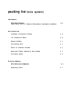
packing list
(bare system)
Hardware
IEC-830 Chassis
(with either ATX or Passive Backplane backplate installed)
x 1
Accessories
Interface Connector Panels
x 2
19" rackmount Ears
x 2
Spare Airfilter
x 1
Grounding wire
x 1
Pack of chassis screws
x 1
Assorted Cable fasteners and straps
x 1
Frontdoor Keys
x 2
Printed Matter
IEC-830 User's Manual
Warranty Card
x 1
x 1
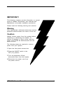
IMPORTANT!
This following chapters provide information on several
types of chassis components, their features and
applications, and proper installation procedures.
Please heed the following warning and cautions.
Warning
Only experienced, authorized electronics service
personnel should access the interior of the unit.
Caution
Always remove power from the system before
inspecting or maintaining the chassis. To
ensure no damage or injury occurs, also the
power cord should be disconnected from the
power source.
The following steps are required to remove
power from your system:
1 Open the front panel access door
2 Place the ON/OFF switch in the
OFF ("0") position
3 Turn all peripherals off and
disconnect them from the chassis
4 Disconnect the power cord from
the power source.
IEC-830 User's Manual
1
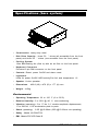
Specifications (bare system)
Construction: heavy-duty steel
Disk Drive Capacity : three 5¼ " drives (all accessible from the front
panel) and three 3½ " drives (one accesible from the front panel)
Cooling System :
12cm Ball-bearing fan (flow in) with an air filter on the front panel
Keyboard Connector :
Pre-wired 5-pin DIN connector on the front panel
Controls: Reset, power On/Off and alarm reset
Indicators:
LEDs for power On/Off, HDD activity,Fan fail, and temperature 1,2
Speaker: 8-ohm speaker
Dimensions:
Weight: 14.5kg
482.6 (W) x 470 (D) x 177 (H) mm
Environmental
Operating Temperature: 32 to 122° F (0 to 50°C)
Relative Humidity: 5 to 95% @ 40° C, non-condensing
Vibration (operating): 5 to 17 Hz, 0.1" double amplitude displacement;
17 to 500 Hz, 1.5G acceleration peak to peak
Shock (operating) : 2.5G @15~20ms (35G @15~20ms non-operating)
Safety : Meets UL/CSA/TUV
EMI : Meets FCC/CE Class B
2
IEC-830 User's Manual
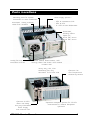
Parts Locations
Mounting panel for special
connectors or cable extensions
Hold-down clamp protects
cards from vibration
Power supply options :
- 250 W Standard PS/2
- 250 W ATX
- 2 x 250 W Mini Redundant
Removable
drivebay offers
space to :
three 5¼ drives
three 3½ drives
Cooling fan with
removable air-filter
Power switch, Reset switch, HDD
activity, Power and Alarm LEDs behind
lockable door
Heavy duty, 120 CFM
ballbearing fan, fully
servicable from front side
Optional 2x 250
Watt Hot-swap,
Hot-plug Redundant
Power Supply
with external Fan
IEC-830 User's Manual
Optional Fan
and Temperature
Monitoring Module
Seperate backplate options for AT/ATX
motherboard or Passive Backplane
operation
3
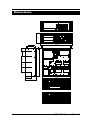
Dimensions
177
482.6
3
41.5
92
92
470
92
92
88.5
431.8
173.2
4
IEC-830 User's Manual
Installation Instructions
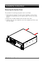
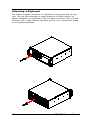
Removing the System Cover
The procedure for removing the system cover is as follows :
1. Power-down the computer. To ensure that no damage or injury occurs,
disconnect all peripherals and the system's power cord from the power
source.
2. Remove the 2 screws located at the rear side of the cover.
3. Carefully slide the cover toward the rear of the chassis and lift the cover
from the chassis.
IEC-830 User's Manual
5
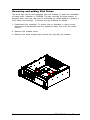
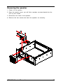
Removing and adding Disk Drives
The drive bay can be fully extracted from the chassis, to ease the installation
of floppy drive, harddisk or CDROM. The bay, secured by three screws, is
hanging down from two rails and is cushioned by rubber buffers to protect it
from shock and vibration. To extract the bay proceed as follows :
1. Power-down the computer. To ensure that no damage or injury occurs,
disconnect all peripherals and the system's power cord from the power
source.
2. Remove the chassis cover
3. Remove the three screws that connect the bay with the chassis
6
IEC-830 User's Manual
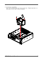
4. Lift the bay out carefully.
(Note: the two EMI springs may loosen at this time. Please keep them in a
save place until the bay is being reinstalled.)
IEC-830 User's Manual
7
5. Two additional 3.5" drive assemblies are piggybacked on the main drive
bay. The first assembly, directly mounted to the main drive bay, is accessible from the front panel and preferably used for FDD drives. The second
assembly is mounted on the first assembly and is not accessible from the
front panel. To separate the two assemblies remove the 4 screws on the
top of the assemblies and slide them backwards and lift them up to release
them from the main drive bay.
6. Place the 5.25" drive inside the main bay, aligning the screw holes (4 at
both side) in the drive with mounting holes in the housing, inserting screws
to secure the disk drive to the main drive bay. (The first drive bay should
be moved away.) The bottom space is of the main drive bay is for
installation of an additional 3.5" HDD.
7. Install the accessible 3.5" FDD and non-accessible HDD into the two
piggybacked drive assemblies and secure the assemblies to the main
drive bay with the 4 top screws. Make sure that the assemblies hooks are
properly seated.
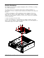
8. If a 10th full-size card
needs to be installed
than omit the installation of the non-accessible HDD bay (2nd
drivebay assembly).
Omitting this drive
creates just enough
space for a full-size
add-on board.
2nd drivebay
for HDD or
10th full-size slot
1st drivebay
exposed, for
FDD/HDD
9. Place the main housing
with drives back into its
previous position inside
the chassis, securing it
with the previously
removed screws.
main drive bay
8
IEC-830 User's Manual
Passive Backplane
The chassis can hold either a passive backplane (ISA or PCI/ISA) or an Baby
AT or ATX motherboard.
You should remove the hold-down-clamp before installing backplane or
motherboard. To do so, remove the two screws at the sides of the clamp and
lift it out.
1. Place the backplane or ATX motherboard into the chassis to find out in
what holes you need to insert plastic spacers. For stability of your boards
make sure to have spacers installed on every corner. Remove the backplane
or ATX motherboard
2. Insert the spacers into the holes
3. Place your backplane or motherbosard into chassis, aligning, and press
down to over the spacers. Inserting additional screws to fix the backplane or
motherboard tightly to the base of chassis.
IEC-830 User's Manual
9
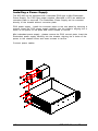
Installing a Power Supply
The IEC-830 can be equipped with a standard PS/2-type or Mini-Redundant
Power Supply. For PS/2 type power supplies (Standard or ATX) an additional
converter plate is requirred. The Redundant Power Supply can be mounted
directly to the chassis without converter plate.
PS/2 power supply : install the converter plate on the rear panel by securing 4
screws. Insert the PS/2 power supply carefully into the chassis, aligning the 4
holes of the power to the plate and insert screws to secure.
Mini redundant power supply : please remove the PS/2 convert plate. Insert the
Redundant power supply carefully into the chassis, aligning the 4 holes of the
power to the chassis holes and insert screws to secure.
Connect power cables
10
IEC-830 User's Manual
Installing Add-on Cards
The IEC-830 uses a hold-down clamp to ensure the add-on cards are located
securely and are protected against shock and vibration. To install your cards
into the passive backplane, proceed as follows.
1. Power Off the system.
2. Remove the chassis cover.
3. Detach the hold-down clamp by removing the 2 screws at both end of the
clamp and lift it off.
4. Locate the desired bus slot location for installation. If you need to use the
8th, 9th or 10th slots in full size cards, put the 3-slot card guide to expend
the slot
5. Remove the substitute I/O bracket from the rear of chassis by releasing
screw.
6. Place the card ends into the appropriate card guide in the chassis. Lower
the card and carefully push the card-edge connector into the slot. Ensure
that the I/O bracket is accessible through the back of chassis.
7. Secure the card-edge I/O bracket to the chassis with the screw.
8. Attach required cables.
9. Release the two screws on the hold-down clamp and adjust the spacers
to pressure the cards in their slots then secure the screws and attach the
hold-down clamp to the chassis.
IEC-830 User's Manual
11
Attaching a Keyboard
The chassis supports connection of a keyboard at front panel and the rear
side. The rear side connection is simply access to the DIN connector on
passive backplane or motherboard. The front panel connection exist of a DIN
connector with a cable that can optionally connect to an onboard box header
on the passive backplane.
12
IEC-830 User's Manual
Internal Wiring
The internal wiring of the chassis includes all signals, switches and
power that connects the seperate components excluding 110/220 Volt
power source wiring.
power switch
reset switch
alarm switch
power LED
HDD LED
fan failure LED
temperature LED
alarm reset
Front Panel Switches and Indicators
1. Power Switch(ATX)
(AT)
connects to
connects to
Power Supply
Power Supply
2. Reset Switch
connects to
CPU card
3. Power On/Off LED
connects to
CPU card
4. HDD active LED
connects to
CPU card
5. Fan fail LED
connects to
Thermal detection board
6. Temperature 1
connects to
Thermal detection board
7. Temperature 2
connects to
Thermal detection board
8. Alarm Reset
connects to
Thermal detection board
Fan and Internal Speaker
9. Speaker Connector
connects to
CPU card
10. Fan DC Power
connects to
Power Supply: +12V, GND
11. Pre-wired keyboard
connect to
Backplane or CPU Card
IEC-830 User's Manual
13
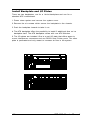
Install Backplate and I/O Plates
There are two backplates: one for a 14-slot backplane and one for a
standard ATX motherboard.
1. Power down system and remove the system cover.
2. Remove the six screws which secure the backplate to the chassis.
3. Push the backplate inwards to take it out.
4. The ATX backplate offers the possibility to install 2 additional fans on he
backplate itself. The ATX backplate comes with one ATX Window.
6. The I/O plates are included. One is a real I/O plate that offers space to
mount interference connectors such as RS-232 and Printer ports. The other
plate is perforated and only meant to increase air flow in the system.
14
IEC-830 User's Manual
Maintenance
Fan Filter Cleaning
It is recommand that the fan filter be cleaned regularly in very dusty environments. The fan filter should be cleaned at least once every 30 days.
1 Power-down the computer. To ensure that no damage or injury occurs,
disconnect the system's power cord from the power source.
2. Open the lockable door on the front panel and you can find the tab of the
fan filter.
3. Remove the fan filter cover by press-down the tab then you can take the
filter out.
4. Wash the filter with a mild soap-and-water solution and dry throughtly.
5. Place the filter and cover back into its orginal position.
6. Reconncet the power cord and power up the system.
tab
IEC-830 User's Manual
15
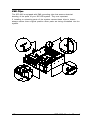
Removing the Fan
1. Power off the system.
2. Open the front door.
3. Remove the two thumb screws on the fan unit and pull the unit up
carefully to lift it out.
4. Disconnect the DC power lines and Speaker wiring of the fan.
5. Remove another 4 screws at the front of the fan unit and then slide the
fan housing cover backwards.
16
IEC-830 User's Manual
Removing the speaker
1. Power off the system.
2. Open the system cover, you will find a speaker mounted beside the fan
unit by two scews.
3. Disconnect the lines of the speaker.
4. Remove the two screws and take the speaker out carefully.
IEC-830 User's Manual
17
EMI Clips
The IEC-830 is equipped with EMI grounding clips that ensure electrical
bonding of the parts of your IEC-830 system. They are important.
If installing or extracting parts of the system causes these clips to loosen
always restore there original position when parts are being reinstalled into the
system.
18
IEC-830 User's Manual
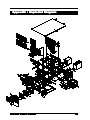
Appendix : Exploded Diagram
3
OR
22
28
OR
29
31
11
12
OR
30
OR
14
13
15
5
32
20
20
27
27
17
16
21
18
21
10
8
21
2
9
20
27
9
9
6
19
7
4
24
23
6
26
25
1
IEC-830 User's Manual
19
Warranty
This product is warranted to be in good working order for a period of one
year from the date of purchase. Should this product fail to be in good working
order at any time during this period, we will, at our option, replace or repair it
at no additional charge except as set forth in the following terms. This
warranty does not apply to products damaged by misuse, modifications,
accident or disaster.
Vendor assumes no liability for any damages, lost profits, lost savings or any
other incidental or consequential damage resulting from the use, misuse of, or
inability to use this product. Vendor will not be liable for any claim made by
any other related party.
Return authorization must be obtained from the vendor before returned
merchandise will be accepted. Authorization can be obtained by calling or
faxing the vendor and requesting a Return Merchandise Authorization (RMA)
number. Returned goods should always be accompanied by a clear problem
description.