1
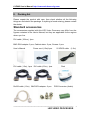
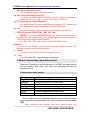
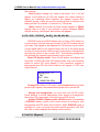
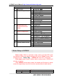
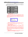
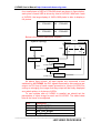
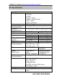
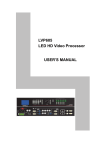
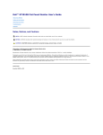
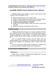
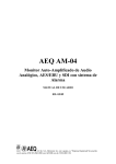
LVP605
LED HD Video Processor
USER’S MANUAL
LVP605 User’s Manual http://www.cnledsourcing.com
TABLE OF CONTENTS
I. Safety precautions
3
II. Packing list
4
III. Connections of hardware
1. Rear view
2. Port description
3. Connection diagram
5
5
6
IV. Frontal panel operations
1. Diagram of frontal panel
2. Button instructions (operation mode)
7
8
V. Setup
(I) User parameter setup
12
1. Enter setup of LVP605
2. Select language
3. Output image setup
4. Text Overlay Setup
5. Brightness / contrast / color / Sharpness
6. Audio configurations
7. Hot Spare setup
8. Factory district setup
12
13
14
15
16
17
17
18
(II) PIP/POP setup
19
(III) Mosaic setup
21
VI. Specifications
26
VII.Copyright info………………………………………………………….28
---------------------------------------------------------------------------------------------------
LED VIDEO PROCESSOR
2
LVP605 User’s Manual http://www.cnledsourcing.com
I.
Safety Precautions
Danger!
There is high voltage in the processor, to prevent any unexpected
hazard, unless you are maintenance, please do not open the cover of the
device.
Warning!
1. This device shall not encounter water sprinkle or splash, please do not
place anything containing water on this device.
2. To prevent fire, keep this device far from any fire source.
3. If this device gives out any strange noise, smoke or smell, please
immediately unplug the power cord from receptacle, and contact local
dealer.
4. Please do not plug or unplug DVI signal cable if the device is
powered on.
Caution!
1. Please thoroughly read this manual before using this device, and keep
it well for future reference.
2. In the event of lighting or when you are not going to use the device for
a long time, please pull the power plug out of receptacle.
3. Nobody other than professional technicians can operate the device,
unless they have been appropriately trained or under guidance of
technicians.
4. To prevent equipment damage or electric shock, please don’t fill in
anything in the vent of the device.
5. Do not place the device near any water source or anywhere damp.
6. Do not place the device near any radiator or anywhere under high
temperature.
7. To prevent rupture or damage of power cords, please handle and keep
them properly.
8. Please immediately unplug power cord and have the device repaired,
when
1) Liquid splashes to the device.
2) The device is dropped down or cabinet is damaged.
3) Obvious malpractice is found or performance degrades.
---------------------------------------------------------------------------------------------------
LED VIDEO PROCESSOR
3
LVP605 User’s Manual http://www.cnledsourcing.com
II.
Packing list
Please unpack the product with care, then check whether all the following
things are included in the package. If anything is found missing, please contact
the dealer.
Standard accessories
The accessories supplied with this LED Video Processor may differ from the
figures contained in the User’s Manual, but they are applicable for the regions
where you live.
DVI cable (150cm), 1pcs
BNC-RCA adapter: 2 pcs, Cabinet stator: 2 pcs, Screws: 6 pcs
User’s Manual
Power cord (1.5m)1pcs
S-VIDEO cable
(1.5m)
,
DVI cable (1.5m), 1pcs DVI cable (0.5m), 1pcs
Disk
Rs232 cable (1.5m) BNC-RCA adapter: 3 pcs
PCB Connector (Audio)
---------------------------------------------------------------------------------------------------
LED VIDEO PROCESSOR
4
LVP605 User’s Manual http://www.cnledsourcing.com
III. Connections of hardware
1. Rear view
Figure 1
2. Port description
1) Video Input
LVP605 supports 10-channel signal input, including:
Port name
Description
3-channel PAL/NTSC composite video input
V1~V3
1-channel PAL/NTSC S-video input
S-Video
1-channel component HD signal input
YPbPr
VGA1~VGA2 2-channel computer analog signal input
1-channel computer DVI digital signal input
DVI
1-channel HDMI digital HD signal input
HDMI
1-channel extended signal input
EXT.
EXT. input signal can be 1xSDI/HD-SDI or 1xVGA/DVI/HDMI.
2) Audio Input
LVP605 supports 5-channel stereo audio switch. Of which, 3
channels are DVI (only available when the input signals are HDMI
signals), HDMI and SDI audios, the other 2 channels are AD1, AD2
external input audio. AD1 and AD2 can be mapped to the any one
of all video inputs, and will be switched synchronous to the
selection of video input signals.
3) Video Output (DVI)
Port
VGA OUT
Description
1-channel analog RGBHV signal output,
it can be connected to a local display
device and used as monitor (it is strongly
---------------------------------------------------------------------------------------------------
LED VIDEO PROCESSOR
5
LVP605 User’s Manual http://www.cnledsourcing.com
recommended to use this port when
operating and setting LVP605).
2 same DVI digital graphic signal output,
DVI OUT1 /
it can be connected with external LED
DVI OUT2
transmission card or LED transmission
box
SDI / HDSDI(OUT) 1-channel digital video signal loop output
1-channel computer DVI digital signal loop
DVI Loop OUT
output
4) Audio Output (AUDIO OUT)
Corresponds to the selected video input signal, output this
channel audio input signals.
5) Signals of other ports
RS232 serial communication port
3. Connection diagram
---------------------------------------------------------------------------------------------------
LED VIDEO PROCESSOR
6
LVP605 User’s Manual http://www.cnledsourcing.com
IV. Frontal panel operations
1. Diagram of frontal panel
1
7
3
2
4
6
10
5
9
8
1) Input selecting buttons (V1, V2, V3, S-Video, DVI, VGA1, VGA2, YPbPr,
EXT.):
They are used to select input signals
2) Setup buttons (Setup, Save, ↑,↓,←,→)
They are used to set the image output parameters of the processor.
---------------------------------------------------------------------------------------------------
LED VIDEO PROCESSOR
7
LVP605 User’s Manual http://www.cnledsourcing.com
3) VGA auto adjustment (Auto)
To automatically adjust VGA input signals
4) Cut / Fade switching mode (C/F):
It is used to select signal switching effects, including seamlessly
switching (CUT) and 0.5s, 1.0s and 1.5s Fade in / Fade out.
5) PC signal bypass output (Bypass):
It is used to switch full screen/partial screen display of PC signals, and
the indicator will indicate the status of current input signal.
6) Info:
It is used to display current settings and information of processor
7) PIP/POP buttons (ON/OFF,M1,M2,M3,M4):
ON/OFF: to turn on/off PIP/POP functions, when the indicator is on,
you can select any signal coming from different groups or current signal as
PIP/POP by using input selecting buttons.
M1,M2,M3,M4: used to set or switch PIP/POP modes.
8) Mosaic
It is used to turn ON/OFF multi-machine cascade mosaic function. The
indicator indicates current splicing status.
9) Freeze
It is used to turn ON/OFF screen freezing function.
10) Text
It is used to add Text, company logo or animation.
2. Button instructions (operation mode):
There are 25 buttons on the frontal panel of LVP605, all these buttons
will be operable after start. they have the following functions as
described below:
1) Select input video source
Port name
V1、V2、V3
S-Video
YPbPr
VGA1、VGA2
DVI
HDMI
EXT.
Description
3-channel PAL/NTSC composite video input
1-channel PAL/NTSC S-video input
1-channel component HD signal input
2-channel computer analog signal input
1-channel computer DVI digital signal input
1-channel HDMI digital HD signal input
1-channel extended signal input(such as SDI/HDSDI)
Switch audio input while operating above buttons; select the audio
signal input from corresponding video input to output it through Audio
OUT.
After selecting input signals, the input signal source you
--------------------------------------------------------------------------------------------------- 8
LED VIDEO PROCESSOR
LVP605 User’s Manual http://www.cnledsourcing.com
currently selected such as “input=HDMI” will appear in the first line
of LCD, while the status of current input signals will appear in the
second line of LCD. If there are no valid signals entered, the
message “no valid signal input” will appear in LCD, and the
corresponding indicator will blink and dark screen appear; if the
signal is valid, the format of input signals such as “ 1080p_60Hz ”
will appear in LCD.
Input= HDMI
1080p_60Hz
Cut
2) VGA input auto adjustment (Auto)
When the current VGA input source of LVP605 is a valid signal,
press this button, LVP605 will automatically adjust the sampling
parameters of the VGA signals, so as to make VGA picture clean
and complete.
In general, this operation is made only when new VGA signal
source is to be connected in. Sometimes user need repetitively do
such adjustment till VGA picture looks clean, complete and stable.
3) Information display (Info)
Press this button to view current settings and information of
LVP605, it consists of 25 items. If you press “Info” again before
LVP605 exit information display, LVP605 will continue to display
the next item of information.
4) Select Cut / Fade mode(C/F)
LVP605 can realize seamless switching effect (Cut) or fading
in/out switching effect (Fade) between any two signals from
different groups as listed below.. But if the signals come from the
same group, dark screen will appear.
A
V1,V2, V3,
S-Video
B
C
DVI, VGA1
HDMI VGA2
D
EXT
Cut (seamlessly switching): while in this mode, “Cut” will
appear in the third line of LCD, the system can seamlessly switch
between different signals. It is also the default mode of LVP605
--------------------------------------------------------------------------------------------------- 9
LED VIDEO PROCESSOR
LVP605 User’s Manual http://www.cnledsourcing.com
after startup.
Fade (fading in fading out): while in this mode, “Cut: 1.0s” will
appear in the third line of LCD, the system can realize fading in
fading out switching effect between the signals coming from
different groups. Users can set the switching time of fading in and
fading out as 0.5 seconds,1.0 second or 1.5 seconds.
Notes: Neither Cut mode nor Fade modes applies to YPbPr
signals, that is to say, if you attempt to switch between YPbPr
signals and any other signal, dark screen will appear.
5) PIP / POP(PIP/POP:On/Off,M1, M2, M3, M4)
PIP/POP mode of LVP605 allows user to insert a PIP window in
current picture, and the size and location of the PIP window can be
set freely. The signals to be displayed in PIP window can be either
current signal itself or any signals which are not in the same group
as that of current picture. Here we call current picture “background”,
and call the picture to be overlaid “PIP”. The following paragraphs
will illustrate the operating procedures of this function:
Enter PIP display mode: Press On/Off button, its indicator will
illuminate, LVP605 will enter PIP display mode, then use Preselect
button to select PIP input signals, in the meantime, signals of
background and PIP and their locations will appear in LCD (see
Figure below):
Background:V1
PAL
PIP:VGA
1280X1024 60Hz
Change PIP: While in PIP mode, use Preselect button to select
proper input signals, the preselected signals will be set as PIP.
Change the background: you must first turn off PIP mode.
Press buttons to select appropriate input signal as background,
then enter PIP mode again, and select a new PIP picture.
Switch PIP/POP display mode: LVP605 allows for presetting
4 PIP/POP display modes, each mode allows for setting its own
background and PIP sizes and locations. While PIP/POP mode is
switched on, user can press the mode switching buttons (M1, M2,
M3, M4) to select appropriate display modes quickly.
6) Part/Full(Bypass)
---------------------------------------------------------------------------------------------------
LED VIDEO PROCESSOR
10
LVP605 User’s Manual http://www.cnledsourcing.com
Press this button to switch between Part / Full display mode.
This function is only available when the current input signal is
PC (VGA 1/ VGA 2/ DVI /HDMI) signal, while other signals can only
be displayed in the Full display mode.
Mode
Full
Part
Description
Full screen display. Entire picture is compressed to
display in LED screen, the moment the indicator above
the button is OFF.
Part screen display. The picture will not be compressed,
but partly exported to entire LED screen, the moment the
indicator above the button is ON.
Caution: when the width and height of current input signals are
less than the width or height of LED display (say the out_Hori_width
or out_Vert_height), Part mode will not work.
7) Freeze
Press this button, the indicator of this button will illuminate
normally, and the current picture will be frozen; press this button
again or perform other signal switching operations, the indicator of
this button will turn out, the picture will get in motion again.
8) Mosaic
Press this button only when current signals are DVI, the indicator
of this button will illuminate, LVP605 will enter Mosaic mode. Press
this button again, the indicator of this button will turn out, and LVP605
will exit Mosaic mode.
Notes: LVP605 will be unable to enter Mosaic mode in the
following events:
1. The input signals are other signals than DVI;
2. BYPASS function has been switched on;
3. The definition of DVI input signals is different from the preset
output definition of the processor.
9) Text
LVP605 can add Text, company logo or animation onto current
picture, while current picture is normally displayed, press Text
button to go to caption adding mode, then select the signal source
--------------------------------------------------------------------------------------------------- 11
LED VIDEO PROCESSOR
LVP605 User’s Manual http://www.cnledsourcing.com
of caption. The captions can be made by office software such as
Powerpoint.
V. Setup
The following settings must be made by relevant qualified
technicians. For ordinary users, unless they have received adequate
technical training, they shouldn’t attempt to make the following
settings!
There are 3 categories available for you to set in LVP605. Technicians
can set these items as necessary, for details see the table below:
Category
User parameter setup
Mosaic setup
PIP/POP setup
Items
Output image setup, text overlay setup
Brightness/Color/Contrast/Definition setup
Hot spare setup, Audio configuration
factory district setup
Input parameter setup
Output parameter setup
Sync. Mosaic setup
Background and PIP output image setup
(
I) User parameter setup
---------------------------------------------------------------------------------------------------
LED VIDEO PROCESSOR
12
LVP605 User’s Manual http://www.cnledsourcing.com
Category
1
Language
2
Output image setup
3
text overlay setup
4
Brightness/Color
Contrast/Definition
setup
5
Audio configuration
6
Hot spare
9
Factory district Setup
Items
1 Language 语言
2 Out Format
3 Out_Hori_Width
4 Out_ Hori _Start
5 Out_Vert_Height
6 Out_Vert_Start
7 Text Mode
8 Threshold Red
9 Threshold Green
10 Threshold Blue
11 Brightness
12 Contrast
13 Saturation
14 Sharpness
15 Audio1 Config
16 Audio2 Config
17 Hot spare < V1→V3>
18 Hot spare < V2→S-Video >
19 Hot spare < HDMI→DVI>
20 Hot spare <VGA1→VGA2>
21 Device ID
22 ADC Calibration
23 De interlace
24 Device init
1. Enter Setup of LVP605
Enter setup: While in operation mode (make sure that PIP mode
and Mosaic mode have been switched off), press “Setup” button, then
press the knob((”Save” key), LVP605 will enter No.1 setup item.
Exit setup: press “Setup” button while in setup mode, LVP605 will
directly exit setup.
After LVP605 enters setup mode, the knobs and 3 buttons in setup
area will respectively have the functions as described in table below:
Name
Knob
Speed
Functions
of The step value in proportion to the
---------------------------------------------------------------------------------------------------
LED VIDEO PROCESSOR
13
LVP605 User’s Manual http://www.cnledsourcing.com
knob
Turn
it
clockwise
Turn
it
anticlockwise
Press it
↑
↓
Setup
speed of knob
Decrease value or select previous value
Increase value or select next value
Save the adjustment or selected values
Move to previous item
Move to next item
Enter or exit setup mode
After LVP605 enters setup mode, the relevant setting information
will be displayed in LCD as per the layout shown in the figure below:
4 :
Out_Vert_Start
200
?
Figure 3
1
3
2
4
As shown in above figure, LCD consists of five sectors:
Sector Description
1
The No. of current setting item
2
?: ask you whether to save the adjustment; !: The
adjustment already be saved and takes effect.
3
Newly adjusted value
4
Name of current setting item
2. Select language
Item 1: “Language 语言 ”
After entering setting mode, LVP605 will enter the first setting item
“Language 语言 ”. LVP605 supports Chinese and English display, turn
the knob to select either of them, then press the knob to save it and
make it valid.
3. Output image setup
---------------------------------------------------------------------------------------------------
LED VIDEO PROCESSOR
14
LVP605 User’s Manual http://www.cnledsourcing.com
LVP605 outputs images from VGA and two DVI output ports. There
are 10 output formats as listed in the table below. User can enter the No.2
setting item “Out Format” to select one of them.
1
2
3
4
5
6
7
8
9
10
Format
1024×768_60
1024×768_75
1280×1024_60
1280×1024_75
1600×1200_60
1920×1080_50
1920×1080_60
1366×768_60
1440×900_60
2048×1152_60
Item 2: “Out Format”
In this item, turn the knob to select either of them, then press the
knob to save it and make it valid.
For example, if you select “1280×1024_60”, it means that the
output definition of LVP605 has been set as 1280×1024, and vertical
refresh rate is 60Hz.
Please select the output definition equal to or greater than the
actual definition of LED screen.
Items 3~6:“Output image setup”
The actual definition of LED can be any value, so we should set
LVP605 to make it output an image with the same definitions as that of
the LED, so that the LED could display a full image. See figure below:
---------------------------------------------------------------------------------------------------
LED VIDEO PROCESSOR
15
LVP605 User’s Manual http://www.cnledsourcing.com
(0,0)
Out_Hori_Start
Out_Hori_Wi
Out_Vert_Start
dth
LVP605 Out Image Area
1080
Out_Vert_Height
LED Dispaly Screen
LVP605 Out Format = 1920×1080
1920
As above figure shows: the size and location of the images in
LVP605 output window for the LED display are defined by the following
4 groups of parameters:
Item No.
3
4
5
6
Parameters
Out_Hori_Width
Out_ Hori _Start
Out_ Vert_Height
Out_Vert_Start
Notes: user can change current parameter settings by rotating the
knob. The speed at which you rotate the knob decides the step value
of the adjustment. The location and size of the output image will be
previewed in the white box while you are making the adjustment, then
you can press the knob to save and validate the settings you made.
4 . Text Overlay Setup
Item No.
7
8
9
10
Setup Item Name
Text Mode
Threshold Red
Threshold Green
Threshold Blue
Item 7: “Text Mode”
---------------------------------------------------------------------------------------------------
LED VIDEO PROCESSOR
16
LVP605 User’s Manual http://www.cnledsourcing.com
LVP605 allows user to set caption knock-out “< threshold” or
“>threshold”. If it is less than threshold value, it means that the
image of caption signal less than current color threshold value will be
added to background, while the part greater than threshold will be
automatically filtered. If it is greater than threshold value, it means
that the image of caption signal greater than current color threshold
value will be added to background.
Item 7~10: ” Threshold Red/Green/Blue”
The three options are used to set R, G, B values respectively as a
certain value within 0~248.
The following figure shows an example of caption adding function.
The caption document in this sample is made using Powerpoint. Its
parameters are set as below:
No. of setup item
7
8
9
10
Background
Setup Item Name
Text Mode
Threshold Red
Threshold Green
Threshold Blue
parameters
<Threshold
248
248
248
Text
Text Overlay
5. Brightness / Contrast / Situration/ Sharpness
LVP605 supports customized brightness, contrast, color Saturation
and definition settings. For details see table below:
Item
Description
Definition
No.
19
Range: 0~100, default value: 50
Brightness
20
Range: 0~100, default value: 50
Contrast
21
Range: 0~100, default value: 50
Saturation
22
Option is “Sharp” or “Normal”,
Sharpness
default value: Normal
---------------------------------------------------------------------------------------------------
LED VIDEO PROCESSOR
17
LVP605 User’s Manual http://www.cnledsourcing.com
Caution: (1). In order to ensure output images in complete gray, the
output parameters are usually set as default values !
(2). The color parameters only apply to V1、V2、V3、S-Video、
YPbPr、SDI and HDMI signals.
6. Audio configurations
LVP605 supports 3-channel stereo audio switch. Of which, 3
channels are DVI (only available when the input signals are HDMI
signals), HDMI and SDI audios,, the other 2 channels are AD1,
AD2 external input audio. AD1 and AD2 can be mapped to the any
one of all video inputs, and will be switched synchronous to the
selection of video input signals.
If DVI( or SDI, HDMI) is configured as external input audio, when
audio signal is switched to DVI( or SDI, HDMI), external audio will be
chosen as input signals, otherwise the audio signals contained in
DVI( or SDI, HDMI) signals will be chosen as input signals.
Item
No.
Description
Definition
23
Audio1 Config
24
Audio2 Config
Audio configuration option for
AD1 port
Audio configuration option for
AD2 port
Notes: AD1, AD2 can’t be allocated to the video input
signals in the same channel!
7. Hot Spare setup
LVP605 supports hot spare of input signals, that is to say, once the
current input signals are lost, the processor will automatically switch to
backup input signals at once, so as to avoid image interruption caused
by the fault of signal source.
Item
17
18
19
20
Description
Hot spare
Hot spare
Hot spare
Hot spare
< V1→V3>
< V2→S-Video >
< HDMI→DVI>
<VGA1→VGA2>
---------------------------------------------------------------------------------------------------
LED VIDEO PROCESSOR
18
LVP605 User’s Manual http://www.cnledsourcing.com
As above figure shows, if ”Hot spare < V1→V3>” is turned on, the
processor will automatically switch the output image to backup port V3
once signal V1 is lost.
8. Factory district setup
The following are factory district setups, users are recommended to
make these setups under the guidance of manufacturer’s technicians,
any improper setting or operation may result in abnormal happening to
the processor.
Item 21: “Device ID”
This item is used to number LVP605 while controlling several
processors by RS232. The number scale is from 1 to 255.
Item 22: “ADC Calibration”
After inputting a analog signal to the video processor whose white
balance has not been calibrated, the picture on the display may appear
some bad phenomena, such as color cast, extreme-darkness. LVP605
can solve the above problems by automatically calibrating white
balance based on the input analog signals(CVBS、S-Video、YPbPr、
VGA). Operating procedures:
Switch to the corresponding analog input signal, enter Item No. 21
“Device ID.” after the processor detects input signals and exports the
signals to the display, press “V1” for 5 times, then press “↑” to shift to
Item 22 “ADC Calibration”, press knob to calibrate white balance.
Caution: The white balance of all video processors has been
calibrated using standard signals in the factory, please don’t set
this item unless necessary!
Item 23: “De interlace”
When CVBS/S-Video/HDMI/SDI signals are interlace input
formats (e.g.: 1080i) and used as PIP, due to limits of the processor,
tremble may take place, it can be dispelled by setting the option “De
interlace”. Operating procedures:
enter Item No. 21 “Device ID”, press “V1” for 5 times, then press
“↑” to shift to Item 23 “De interlace”, turn knob to select “ON”, and
press knob to make it valid.
---------------------------------------------------------------------------------------------------
LED VIDEO PROCESSOR
19
LVP605 User’s Manual http://www.cnledsourcing.com
Item 24: “Device Init”
After entering item No. 21 “Device ID”, press “V1” for 5 times, then
press “↑” to shift to Item 24: “Device Init”, turn knob to select “Yes”,
then press knob to reset the factory settings, the moment the system
will remind you “Please restart.”, just follow the instruction.
(II) PIP/POP setup
Category
1
background Output
setup
2
PIP Output setup
Items
1 Main_ Hori_Width
2 Main_ Hori_Start
3 Main_Vert_Height
4 Main_Vert_Start
5 PIP_ Hori_Width
6 PIP _ Hori_Start
7 PIP _Vert_Height
8 PIP _Vert_Start
LVP605 allows for presetting 4 PIP/POP display modes, each
mode allows for setting any background and PIP/POP size and location
you need.
(0,0)
PIP_Hori_Start
PIP_Width
PIP_Vert_Start
Main _Vert_Height
Main window
PIP Window
1080
Main_Hori_Start
PIP_Height
Main_Vert_Height
LVP605Out Format = 1920×1080
Main_Hori_Width
1920
---------------------------------------------------------------------------------------------------
LED VIDEO PROCESSOR
20
LVP605 User’s Manual http://www.cnledsourcing.com
Figure 5
As above figure shows: the size and location of the images in
LVP605 background and PIP output window for the LED display are
defined by the following 8 groups of parameters:
Item
1
2
3
4
5
6
7
8
Description
Main_ Hori_Width
Main_ Hori_Start
Main_Vert_Height
Main_Vert_Start
PIP_ Hori_Width
PIP _ Hori_Start
PIP _Vert_Height
PIP _Vert_Start
Operating procedures:
Enter PIP/POP setup mode: while PIP/POP mode is turned
on (make sure that Mosaic mode have been switched off), press
“Setup” button, then press the knob, LVP605 will enter the first
setup item of PIP/POP setup mode. The information as follows will
appear in LCD:
1.
Main_Hori_width
1216
?
PIP/POP Mode=M1
Switch current PIP modes: press mode buttons (i.e.: M1, M2,
M3, M4), the processor will directly switch current PIP modes.
Switch adjustment items: press ” ↑” and ” ↓” to switch
current adjustment items.
Change output parameters: user can change current
parameter settings by rotating the knob. The speed at which you
rotate the knob decides the step value of the adjustment. The
locations of the background and PIP will be previewed respectively
in the white rectangle and blue rectangle while you are making the
adjustment, then you can press the knob to save and validate the
settings you made.
Exit PIP/POP setup mode: directly press “Setup” button while
in PIP/POP setup mode, LVP605 will exit directly.
---------------------------------------------------------------------------------------------------
LED VIDEO PROCESSOR
21
LVP605 User’s Manual http://www.cnledsourcing.com
(III) Mosaic setup
Category
Input image setup
Items
1 Out_Hori_Width
2 Out_ Hori _Start
3 Out_ Vert_Height
4 Out_Vert_Start
5 In_Hori_Width
6 In_ Hori _Start
7 In_ Vert_Height
8 In_Vert_Start
9 Mosaic Mode
The maximum output definition of LVP605 is 2048×1152 or
1600×1200, to drive so high definition, LED display requires two
transmission cards in cascade, so LVP605 provides two locations to
hold two built-in transmission cards; if the actual definition of LED
display exceeds the maximum output definition of LVP605, you may
divide the whole LED into pieces of smaller LED screen, then put them
together in Mosaic manner by connecting multiple sets of LVP605 in
parallel, so as to integrate the smaller pieces of LED into a large LED
display.
With frame synchronization technology, LVP605 solves the
problems of misplacement and delay of output image existing in
ultra-large LED mosaic, able to provide real-time, clear and fluent
displaying effects.
LVP605 supports multi-machine mosaic in parallel, in this way,
smaller pieces of LEDs can be integrated into a large display. For
example, if the output definition of LVP605 is set as 1920×1080, and
we put 2 sets of LVP605 together horizontally in parallel, it will be able
to connect any LED display of up to 3840×1080 pixels.
Below is a 2×2 mosaic example using 4 sets of LVP605, telling us
how to use multi-machine cascade of LVP605 and what we should pay
attention to.
The definition of each LED is 3456×1920, we can divide it into the
---------------------------------------------------------------------------------------------------
LED VIDEO PROCESSOR
22
LVP605 User’s Manual http://www.cnledsourcing.com
four small pieces of LED of 1728×960 pixels as shown in figure below,
each piece of small LED is driven by a set of LVP605. With total 4 sets
of LVP605, the large display of 3456×1920 pixels is able to display a
full picture.
#1(1728×960) #2(1728×960)
#3(1728×960) #4(1728×960)
Below is the system topological diagram:
3456
System Topology
Input signals
#1
#2
#3
#4
1920
DVI
LVP605#0
DVI
LVP605#1
LOOP OUT
LVP605#3
LVP605#2
LVP605#4
LOOP OUT
As above figure shows, all input signals are connected to and
switched by #0 LVP605, the DVI signals exported by this machine are
output via DVI loop of each mosaic processor to 4 sets of LVP605 for
cutting or enlarging, the image that they output will be finally displayed
as a whole picture in 4 pieces of LEDs.
To use multiple sets of LVP605 in parallel, we should set the
parameters of input image for each set of LVP605. The table below
lists all the items to be adjusted.
Item
1
2
3
4
Description
Out_Hori_Width
Out_ Hori _Start
Out_ Vert_Height
Out_Vert_Start
---------------------------------------------------------------------------------------------------
LED VIDEO PROCESSOR
23
LVP605 User’s Manual http://www.cnledsourcing.com
5
6
7
8
9
In_Hori_Width
In_ Hori _Start
In_ Vert_Height
In_Vert_Start
Mosaic Mode
Caution: while in Mosaic mode, in order to keep the consistency of
the image, each processor must be set to be identical in the
parameters of brightness/color/gray/definition.
Enter setup: While in operation mode (mosaic mode is turned on),
press “Setup” button, then press OK button, LVP605 will enter mosaic
setup item.
Exit setup: press “Setup” button while in setup mode, LVP605 will
directly exit setup.
The setup of 5 PCS LVP605 is as follow::
Setup items
parameters of processor
#0
#1
#2
#3
#4
1920
1728
1 Out_Hori_Width
0
2 Out_ Hori _Start
960
3 Out_ Vert_Height 1080
0
4 Out_Vert_Start
Out Format
5
6
7
8
9
1920×1080
In_Hori_Width
1920
960
960
960
960
In_ Hori _Start
0
0
960
0
960
In_ Vert_Height
1080
540
960
540
540
In_ Vert_Start
0
0
0
540
540
Mosaic Mode
Not Sync
Sync
In order to ensure all output images are synchronous to each other,
please note the following settings:
1. The input signals can be only DVI signals, and if the
processor is in mosaic mode, it will be unable to switch input
signals;
2. All the 5 processors must to be set to be the same in output
definitions.
3. Please reduce the number of DVI rings of the processor to
the most extent, so as to prevent signal instability caused by
signal attenuation.
Items 1~4:“ Output image setup ”
Items 3~6 of user setup menu are image output parameters, the
---------------------------------------------------------------------------------------------------
LED VIDEO PROCESSOR
24
LVP605 User’s Manual http://www.cnledsourcing.com
parameters adjusted are the data in the same group.
1#
LVP605
2#
LVP605
(0,0)
(960,0)
(0,540)
(960,540)
Input image
1080
1920
3#
LVP605
4#
LVP605
LED Screen
960
1728
Figure 5
Item 5:“In_Hori_Width ”
It is used to set the horizontal width of input image from which
LVP605 will capture.As shown in Figure 5, the width of input image for
the 4 sets of LVP605 should be set as:
In_Hori_Width = 1 / 2
Item 6:“In_ Hori _Start ”
It is used to set the horizontal start point of input image from which
LVP605 will capture. As shown in Figure 5, the the horizontal start point
---------------------------------------------------------------------------------------------------
LED VIDEO PROCESSOR
25
LVP605 User’s Manual http://www.cnledsourcing.com
of the four sets of LVP605 are set as below respectively:
1# LVP605 In_ Hori _Start = 0
2# LVP605 In_ Hori _Start = 960
3# LVP605 In_ Hori _Start = 0
4# LVP605 In_ Hori _Start = 960
Item 7:“ In_ Vert_Height ”
It is used to set the vertical height of input image from which
LVP605 will capture. As shown in Figure 5, the the vertical height of
the four sets of LVP605 are set as below respectively:
In_ Vert_Height = 540
Items 6:“ In_ Vert_ Start ”
It is used to set the vertical start point of input image from which
LVP605 will capture. As shown in Figure 5, the the vertical start point of
the four sets of LVP605 are set as below respectively:
1# LVP605 In_ Vert_ Start = 0
2# LVP605 In_ Vert_ Start = 0
3# LVP605 In_ Vert_ Start = 540
4# LVP605 In_ Vert_ Start = 540
Item 9: “ Sync Mosaic”
The system provides the options of “Sync Mosaic” and “Not sync
Mosaic”. “Sync Mosaic” ensures all output images are completely
real-time and synchronous to each other; while “Non-sync Mosaic” has
better compatibility, and is usually used for mosaic commissioning.
---------------------------------------------------------------------------------------------------
LED VIDEO PROCESSOR
26
LVP605 User’s Manual http://www.cnledsourcing.com
VII. Specifications
Inputs
Nums/Type
Video system
Composite Video
Scope/Impedance
S-VIDEO
Scope/Impedance
VGA Format
VGA Scope/Impedance
DVI Format
HDMI 1.3 Format
( HDCP )
YPbPr Format
YPbPr
Scope/Impedance
SDI format
HDSDI
3GSDI format
AUDIO
Scope/Impedance
Input Connectors
Outputs
Nums/Type
3×Composite
1×S-Video
1×YPbPr
2×VGA(RGBHV)
1×HDMI(1.3a with HDCP )
1×DVI(HDMI)
1×EXT.(Extended)
PAL/NTSC
1V(p_p)/ 75Ω
Y:1.0V(p_p)/ 75Ω,C:0.35V(p_p)/ 75Ω
PC(VESA)
≤2048x1152 @60Hz
R、G、B = 0.7 V(p_p)/ 75Ω
SD/HD(CEA-861) ≤1920x1080P @60Hz
PC(VESA)
≤2048x1152 @60Hz
SD/HD(CEA-861) ≤1920x1080P @60Hz
PC(VESA)
≤2048x1152 @60Hz
SD/HD(CEA-861) ≤1920x1080P @60Hz
Y= 1.0V(p_p)/ 75Ω
Pb= 0.35V(p_p)/ 75Ω
Pr= 0.35V(p_p)/ 75Ω
SDI-SMPTE 259M-C 576i @50Hz
480i @60Hz
HDSDI-SMPTE
1080P @50Hz/60Hz
292M
1080i @50Hz/60Hz
SMPTE 274M/296M 720P @60Hz
2.0Vp-p/10KΩ
VGA:15pin D_Sub(Female)
DVI:24+1 DVI_D
YPbPr: BNC×3
Composite:BNC
S-VIDEO:4pin mini DIN(Female)
SDI/ HDSDI :BNC
1×VGA(RGBHV)
2×DVI
---------------------------------------------------------------------------------------------------
LED VIDEO PROCESSOR
27
LVP605 User’s Manual http://www.cnledsourcing.com
VGA/DVI Format
VGA Scope/Impedance
Output Connectors
Others
Control
Power
Operating Temp
Humidity
Dimensions(Package)
Weight(G.W.)
Weight(N.W.)
1024×768@60Hz/75Hz
1280×1024@60Hz/75Hz
1600×1200@60Hz
1920×1080p@50Hz/60Hz
1366×768@60Hz
1440×900@60Hz
2048×1152@60Hz
R、G、B = 0.7 V(p_p)/ 75Ω
VGA OUT:15pin D_Sub(Female)
DVI OUT1:24+5 DVI_I
DVI OUT2:24+1 DVI_D
Panel Button,RS232
100-240VAC 35W 50/60Hz
5-40 ℃
15-85%
166 mm (height) ×428mm (width) ×545mm
(length)
5.0 Kg
3.2Kg
Dimensions:
---------------------------------------------------------------------------------------------------
LED VIDEO PROCESSOR
28
LVP605 User’s Manual http://www.cnledsourcing.com
VIII. Copyright info
The copyright of this Manual is owned by SHENZHEN VDWALL
CO.,LTD., unless with prior consent of VDWALL, nobody is permitted to
copy or use any part or all of the information contained herein.
This Manual is provided for reference only, VDWALL reserves right
to change the product appearance, dimensions and specifications from
time to time without notice to users.
---------------------------------------------------------------------------------------------------
LED VIDEO PROCESSOR
29