1
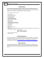
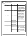
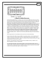
Infinity 58X LS Engine Harness
System User Manual
30-3801
THIS PRODUCT IS LEGAL IN CALIFORNIA FOR RACING VEHICLES ONLY
AND SHOULD NEVER BE USED ON PUBLIC HIGHWAYS.
AEM Performance Electronics
AEM Performance Electronics, 2205 126th Street Unit A, Hawthorne, CA 90250
Phone: (310) 484-2322 Fax: (310) 484-0152
http://www.aemelectronics.com
Instruction Part Number: 10-3801
Document Build 10/20/2015
2
AEM Infinity Harness Manuals
Introduction
1
This Infinity Layover Harness was designed for the GM LS Engine 58x (manual transmission). The
harness includes all standard GM (or equivalent) connectors for direct plug-in fitment, and requires
minimal wiring to complete the Power Distribution Center (PDC) connections. The Infinity ECU is sold
separately, and includes base configuration files for the GM LS Engines 58x.
Connector interface features include:
·
·
·
·
·
·
·
·
·
·
·
·
·
·
·
·
·
1 wire alternator
Manifold Pressure Sensor
Fuel Pressure Sensor
Oil Pressure Sensor
Air Temperature Sensor
Coolant Temperature Sensor
Drive By Wire Throttle Body
Harness Flash
Lambda (UEGO)
Drive By Wire Accelerator Pedal
4 Wire GM Stepper IAC (Optional)
Crank Position
Cam Position
8x Injectors
Bank1 and Bank2 Coils
2x Knock
Power Distribution Center with 5 automotive relays (fuse protected), distributed coil and injector power,
fuel pump power, fan power, accessory power
3801 Kit 2Contents
· Infinity 58X LS Engine Harness
· User Instructions
ECU Connectors
3
The Infinity-6/8h/8/10 ECUs use the MX123 Sealed Connection System from Molex. AEM strongly
recommends that users become familiar with the proper tools and procedures before attempting any
modifications or additions to these connector housings. The entire Molex user manual can be
downloaded direct from Molex at http://www.molex.com/mx_upload/family//MX123UserManual.pdf
Splice 4Savers
Some harness assemblies include connector housings called splice savers. These are used to
distribute power and ground circuits throughout the harness without requiring unreliable crimp splices
within the harness. There are no external interfaces required at these connectors. Example shown
below.
© 2015 AEM Performance Electronics
3
3801/3805/3809 Power
5 Distribution Center
Included in the harness is a Power Distribution Center (PDC), pre-populated with the required relays and
fuses for correct operation of accessory loads. The PDC comes with a bundle of flying leads that need to
be properly wired as part of the installation. Flying leads include switched ignition, an optional fused
+12V relay power output for auxiliary loads, and optional fused +12V relay outputs for a Fuel Pump and
Coolant Fan.
© 2015 AEM Performance Electronics
4
AEM Infinity Harness Manuals
3801 Installation
6
Tips
Battery Power and Ground
The main power and ground feeds (R1-R4) include a heavy duty ring terminal and should only be modified
if absolutely necessary. The red battery power leads are intended to be installed on the starter solenoid
positive terminal. The two black battery ground terminals are intended to be connected to a bold on the
rear of each cylinder head.
© 2015 AEM Performance Electronics
5
Flying Leads
A bundle of flying lead wires is included for various input and output functions. They are described below.
Wire
Description
PNK/WHT Ignition Switch - +12V power in crank and run positions only. Recommend that no other
loads or devices be connected to this wire
RED/BLU Relay controlled fused fan power - connect to fan motor +
RED/GRN Relay controlled fused fuel pump power - connect to fuel pump motor +
RED
Relay controlled fused auxiliary power - connect to optional relay primary coil +
BRN
DIG3 - for frequency or switched inputs - see ECU pinout for hardware limitations
WHT/VIO Lowside 5 - switched ground output - see ECU pinout for hardware limitations
YEL
DIG5 - for frequency or switched inputs - see ECU pinout for hardware limitations
WHT/YEL Lowside 1 - switched ground output - see ECU pinout for hardware limitations
WHT/RED VR+ 3 - for mag frequency inputs - connect to signal positive
WHT/BLU VR- 3 - for mag frequency inputs - connect to signal negative
3801 Harness
7 Layout
If viewing this manual electronically, an embedded document containing the above layout can be found
here.
© 2015 AEM Performance Electronics
6
AEM Infinity Harness Manuals
3801 Harness
8 Schematic
If viewing this manual electronically, an embedded document containing the above schematic can be
found here.
3801 Harness
9 Pinouts
36-3801 - Infinity Pinout GM LSX 58X for Venice Platform
C1
Infinity Connector C1
80 Way F Receptacle 0.64 2.8 Series Sealed (BL)
Destination
Pin
Wire Color Gauge
1
2
3
C1-01
C1-02
WHT/VIO
20
F1
Low sideSw itch_5
C1-03
RED/BLK
20
C12-2
Injector 7/Low sideSw itch_6
C1-04
DK BLU/WHT
20
C11-2
Injector 8/Low sideSw itch_7
C1-05
WHT
18
C23-4
UEGO1_Heat
C1-06
GRN
20
C23-2
UEGO1_IA
C1-07
RED
20
C23-6
UEGO1_IP
C1-08
BLK
20
C23-1
UEGO1_UN
C1-09
ORG
20
C23-5
UEGO1_VM
© 2015 AEM Performance Electronics
7
C1-10
RED
20
P1-8
+12V_R8C_CPU
C1-11
DK GRN/WHT
20
C9-C
Coil4
C1-12
LT BLU
20
C10-F
Coil3
C1-13
RED/WHT
20
C9-B
Coil2
C1-14
VIO
20
C10-G
Coil1
C1-15
LT BLU/WHT
20
C9-F
Coil6
C1-16
DK GRN
20
C10-C
Coil5
VIO
20
P1-37
Low sideSw itch_2
C1-23
BLK/WHT
20
C5-A
AGND_1
C1-24
BLK
22
S1
AGND_1
C1-25
WHT
22
C20-A
Crank_Hall
C1-26
GRN
22
C19-C
Cam1_Hall
BRN
20
F1
Digital_In_3
C1-30
YEL
20
F1
Digital_In_5
C1-31
TAN
20
C10-B
COIL7/Digital_In_6
C1-32
VIO/WHT
20
C9-G
COIL8/Digital_In_7
C1-33
BLK
20
C3-K
PGND
C1-38
YEL
20
C26-B
Analog_In_Temp_1
C1-39
TAN
20
C27-B
Analog_In_Temp_2
C1-41
VIO/WHT
20
P1-13
Low sideSw itch_0
C1-42
WHT/YEL
20
F1
Low sideSw itch_1
C1-43
BLK
20
C3-K
PGND
C1-44
DK BLU/WHT
20
C8-A
KnockSensor_1
C1-45
LT BLU/WHT
20
C7-A
KnockSensor_2
C1-46
BLK
20
C3-L
PGND
C1-17
C1-18
C1-19
C1-20
C1-21
C1-22
C1-27
C1-28
C1-29
C1-34
C1-35
C1-36
C1-37
C1-40
© 2015 AEM Performance Electronics
8
AEM Infinity Harness Manuals
C1-47
YEL/WHT
20
P1-1
+12V_Relay_Cntrl
C1-48
PNK/WHT
20
P1-27
+12V_SW
C1-49
ORG
22
S2
+5V_Out_1
C1-50
GRY
20
C6-A
+5V_Out_1
C1-51
DK BLU
20
C25-D
Analog_In_7
C1-52
LT GRN
20
C30-B
Analog_In_8
C1-53
GRN/BLU
20
C29-C
Analog_In_9
C1-56
WHT/BLU
20
F1
VR-_IN3
C1-57
WHT/RED
20
F1
VR+_IN3
C1-58
RED
20
RES1
C1-59
LT BLU/BLK
20
C21-C
Stepper_1B
C1-60
LT GRN/BLK
20
C21-A
Stepper_2B
C1-61
BRN
20
C25-A
DBW1 Motor -
C1-62
YEL
20
C25-B
DBW1 Motor +
C1-63
RED
20
C2-L
+12V
C1-64
YEL/BLK
20
C13-2
Injector 6
C1-65
BLU/RED
20
C14-2
Injector 5
C1-66
LT BLU/BLK
20
C15-2
Injector 4
C1-67
BLK
20
C3-L
PGND
C1-68
RED
20
C2-G
+12V
C1-69
RED/BLK
20
C22-E
Analog_In_19
C1-70
DK BLU/RED
20
C22-B
Analog_In_18
C1-71
RED/GRN
20
C25-F
Analog_In_16
C1-72
RED
20
C24-2
Flash_Enable
C1-73
GRN
20
C28-C
Analog_In_13
C1-76
PNK/BLK
20
C16-2
Injector 3
C1-77
LT GRN/BLK
20
C17-2
Injector 2
C1-78
BLU
20
C18-2
Injector 1
C1-79
LT GRN/WHT
20
C21-B
Stepper_2A
C1-80
LT BLU/WHT
20
C21-D
Stepper_1A
C1-54
C1-55
C1-74
C1-75
C2
280 METRI-PACK 12F
© 2015 AEM Performance Electronics
9
Pin
Wire Color Gauge
Destination
1
A
RED
12
P1-2
B
RED
20
P1-22
C
RED
20
P1-34
D
RED
20
P1-46
E
RED
20
P1-48
G
RED
20
C1-68
H
RED
20
F1
K
BRN
20
C23-3
L
RED
20
C1-63
2
3
F
J
M
C3
Pin
280 METRI-PACK 12F
Wire Color Gauge
Destination
1
2
3
A
RED
12
R3
B
RED
12
R4
C
RED
12
P1-7
D
RED
12
P1-15
E
RED
12
P1-23
F
RED
12
P1-16
G
BLK
12
R1
H
BLK
12
R2
J
BLK
18
C9-A
K
BLK
20, 22, 20
C1-33
P1-25
C1-43
L
BLK
20, 22, 20
C1-67
P1-39
C1-46
M
BLK
18
10-A
C4
Pin
280 METRI-PACK 12F
Wire Color Gauge
Destination
1
A
RED
12
P1-40
B
RED
20
C18-1
© 2015 AEM Performance Electronics
2
3
10
AEM Infinity Harness Manuals
C
RED
20
C16-1
D
RED
18
C10-H
E
RED
20
C14-1
F
RED
20
C12-1
G
RED
12
P1-26
H
RED
18
C17-1
J
RED
18
C15-1
K
RED
18
C9-H
L
RED
20
C13-1
M
RED
20
C11-1
C5
Pin
280 METRI-PACK 12F
Wire Color Gauge
Destination
1
2
C7-B
A
BLK/WHT
20
C1-23
B
BLK/WHT
20
C9-E
C
BLK/WHT
20
C8-B
D
BLK/WHT
20
C26-A
E
BLK/WHT
20
C27-A
F
BLK/WHT
20
C28-A
G
BLK/WHT
20
C29-A
H
BLK/WHT
20
C30-A
J
BLK/WHT
20
C10-E
K
BLK/WHT
20
C22-F
L
BLK/WHT
20
C22-A
M
BLK/WHT
20
C25-C
3
C6
Pin
A
280 METRI-PACK 12F
Wire Color Gauge
Destination
1
GRY
20
C1-50
C
GRY
20
C28-B
D
GRY
20
C30-C
E
GRY
20
C22-C
F
GRY
20
C29-B
2
3
B
© 2015 AEM Performance Electronics
11
G
GRY
20
C22-D
H
GRY
20
C25-E
J
K
L
M
C7
Pin
2 Way F GT 150 Series, Sealed (BK)
Wire Color Gauge
Destination
1
A
LT BLU/WHT
20
C1-45
B
BLK/WHT
20
C5-A
2
3
C8
Pin
2 Way F GT 150 Series, Sealed (BK)
Wire Color Gauge
Destination
1
A
DK BLU/WHT
20
C1-44
B
BLK/WHT
20
C5-C
2
3
C9
Pin
Knock2
Knock1
7 Way F Metri-Pack 150 Series Sealed (Cream)
Wire Color Gauge
Destination
1
A
BLK
18
C3-J
B
RED/WHT
20
C1-13
C
DK GRN/WHT
20
C1-11
E
BLK/WHT
20
C5-B
F
LT BLU/WHT
20
C1-15
G
VIO/WHT
20
C1-32
H
RED
18
C4-K
2
3
Coil Bank 2
D
C10
Pin
A
7 Way F Metri-Pack 150 Series Sealed (Cream)
Wire Color Gauge
BLK
© 2015 AEM Performance Electronics
18
Destination
1
C3-M
2
3
Coil Bank 1
12
AEM Infinity Harness Manuals
B
TAN
20
C1-31
C
DK GRN
20
C1-16
E
BLK/WHT
20
C5-J
F
LT BLU
20
C1-12
G
VIO
20
C1-14
H
RED
18
C4-D
D
C11
Pin
Wire Color Gauge
Destination
1
1
RED
20
C4-M
2
DK BLU/WHT
20
C1-4
2
3
INJ8
C12
Pin
Wire Color Gauge
Destination
1
1
RED
20
C4-F
2
RED/BLK
20
C1-3
2
3
INJ7
C13
Pin
Wire Color Gauge
Destination
1
1
RED
20
C4-L
2
YEL/BLK
20
C1-64
2
3
INJ6
C14
Pin
Wire Color Gauge
Destination
1
1
RED
20
C4-E
2
BLU/RED
20
C1-65
2
3
INJ5
C15
Pin
Wire Color Gauge
Destination
1
2
3
INJ4
© 2015 AEM Performance Electronics
13
1
RED
20
C4-J
2
LT BLU/BLK
20
C1-66
C16
Pin
Wire Color Gauge
Destination
1
1
RED
20
C4-C
2
PNK/BLK
20
C1-76
2
3
INJ3
C17
Pin
Wire Color Gauge
Destination
1
1
RED
20
C4-H
2
LT GRN/BLK
20
C1-77
2
3
INJ2
C18
Pin
Wire Color Gauge
Destination
1
1
RED
20
C4-B
2
BLU
20
C1-78
2
3
INJ1
C19
Pin
Wire Color Gauge
Destination
1
A
ORG
22
S2
B
BLK
22
S1
C
GRN
22
C1-26
2
3
CAM
C20
Pin
Wire Color Gauge
Destination
1
A
WHT
22
C1-25
B
BLK
22
S1
C
ORG
22
S2
© 2015 AEM Performance Electronics
2
3
CRANK
14
AEM Infinity Harness Manuals
C21
Pin
Wire Color Gauge
Destination
1
A
LT GRN/BLK
20
C1-60
B
LT GRN/WHT
20
C1-79
C
LT BLU/BLK
20
C1-59
D
LT BLU/WHT
20
C1-80
2
3
IDLE
C22
Pin
Wire Color Gauge
Destination
1
A
BLK/WHT
20
C5-L
B
DK BLU/RED
20
C1-70
C
GRY
20
C6-E
D
GRY
20
C6-G
E
RED/BLK
20
C1-69
F
BLK/WHT
20
C5-K
2
3
PEDAL
C23
Pin
Wire Color Gauge
Destination
1
1
BLK
20
C1-8
2
GRN
20
C1-6
3
BRN
20
C2-K
4
WHT
18
C1-5
5
ORG
20
C1-9
6
RED
20
C1-7
2
3
UEGO
C24
Pin
Wire Color Gauge
Destination
1
1
RED
20
P1-8
2
RED
20
C1-72
2
3
FLASH
C25
© 2015 AEM Performance Electronics
15
Pin
Wire Color Gauge
Destination
1
A
BRN
20
C1-61
B
YEL
20
C1-62
C
BLK/WHT
20
C5-M
D
DK BLU
20
C1-51
E
GRY
20
C6-H
F
RED/GRN
20
C1-71
2
3
THROTTLE
C26
Pin
Wire Color Gauge
Destination
1
A
BLK/WHT
20
C5-D
B
YEL
20
C1-38
2
3
COOLANT
C27
Pin
Wire Color Gauge
Destination
1
A
BLK/WHT
20
C5-E
B
TAN
20
C1-39
2
3
AIR TEMP
C28
Pin
Wire Color Gauge
Destination
1
A
BLK/WHT
20
C5-F
B
GRY
20
C6-C
C
GRN
20
C1-73
2
3
OIL PRESS
C29
Pin
Wire Color Gauge
Destination
1
A
BLK/WHT
20
C5-G
B
GRY
20
C6-F
C
GRN/BLU
20
C1-53
C30
© 2015 AEM Performance Electronics
2
3
FUEL PRESS
16
AEM Infinity Harness Manuals
Pin
Wire Color Gauge
Destination
1
A
BLK/WHT
20
C5-H
B
LT GRN
20
C1-52
C
GRY
20
C6-D
2
3
MAP
C31
Pin
Wire Color Gauge
Destination
1
2
3
ALT
A
B
RED
20
RES1
C
D
RES
1
Pin
Wire Color Gauge
Destination
1
RED
20
C31-B
RED
20
C1-58
2
3
P1
Pin
ALT
Pow er Distribution Module, PDM-T3AA1
Wire Color Gauge
Destination
1
1
YEL/WHT
20
C1-47
2
RED
12
C2-A
3
RED
12, 22
P1-9
4
RED
20
R4
7
RED
12
C3-C
8
RED
20, 20
C1-10
9
RED
12
P1-3
10
RED
22
P1-3
11
RED
12
P1-33
12
RED
12
P1-21
2
3
P1-10
5
6
C24-1
© 2015 AEM Performance Electronics
17
13
VIO/WHT
20
C1-41
14
RED/GRN
12
F1
15
RED
12
C3-D
16
RED
12
C3-F
19
RED
12
P1-47
20
RED
12
P1-45
21
RED
12
P1-12
22
RED
20
C2-B
23
RED
12
C3-E
24
RED
12
R3
25
BLACK
20
C3-K
26
RED
12
C4-G
27
PNK/WHT
20
C1-48
PNK/WHT
22
F1
33
RED
12
P1-11
34
RED
20
C2-C
37
VIO
20
C1-21
38
RED/BLU
12
F1
39
BLK
22
C3-L
40
RED
12
C4-A
45
RED
12
P1-20
46
RED
20
C2-D
47
RED
12
P1-19
48
RED
20
C2-E
17
18
28
29
30
31
32
35
36
41
42
43
44
© 2015 AEM Performance Electronics
18
AEM Infinity Harness Manuals
F1
Pin
Flying Leads
Wire Color Gauge
Destination
1
WHT/BLU
20
C1-56
WHT/RED
20
C1-57
WHT/YEL
20
C1-42
YEL
20
C1-30
WHT/VIO
20
C1-2
BRN
20
C1-28
RED
20
C2-H
RED/BLU
12
P1-38
RED/GRN
12
P1-14
PNK/WHT
22
P1-31
2
3
S1
Pin
Splice
Wire Color Gauge
Destination
1
IN
BLK
22
C1-24
OUT
BLK
22
C20-B
OUT
BLK
22
C19-B
2
3
S2
Pin
Splice
Wire Color Gauge
Destination
1
IN
ORG
22
C1-49
OUT
ORG
22
C20-C
OUT
ORG
22
C19-A
2
3
R1
Pin
Ring Terminal
Wire Color Gauge
BLK
12
Destination
1
2
Batt-
C3-G
R2
Pin
3
Ring Terminal
Wire Color Gauge
Destination
Batt-
© 2015 AEM Performance Electronics
19
1
BLK
12
2
3
C3-H
R3
Pin
Ring Terminal
Wire Color Gauge
RED
12,12
Destination
1
2
C3-A
P1-24
Batt+
3
R4
Pin
Ring Terminal
Wire Color Gauge
RED
12, 20
Destination
1
2
C3-B
P1-4
Batt+
3
Infinity-6/8h10ECU Pinout
Infinity
Pin
C1-1
Hardware Ref.
Lowside 4
Hardware Specification
Lowside switch, 1.7A max,
NO internal flyback diode.
Notes
See Setup Wizard Page "Output
Function Assignment" for setup
options.
12V pullup
C1-2
Lowside 5
Lowside switch, 6A max with
internal flyback diode.
Inductive load should NOT
have full time power.
See Setup Wizard Page "Output
Function Assignment" for setup
options.
12V pullup
C1-3*
Lowside 6 (*Infinity-6 Lowside switch, 6A max with
Only)
internal flyback diode.
Inductive load should NOT
have full time power.
See Setup Wizard Page "Output
Function Assignment" for setup
options.
No pullup
C1-3**
Injector 7
(**Infinity-8H Only)
For use with high impedance
(10-15 ohms) injectors only,
1.7A max.
Available on P/N 30-7108 only
C1-4*
Lowside 7
(*Infinity-6 Only)
Lowside switch, 6A max, NO
internal flyback diode.
See Setup Wizard Page "Output
Function Assignment" for setup
options.
No pullup
C1-4**
Injector 8
(**Infinity-8H Only)
© 2015 AEM Performance Electronics
For use with high impedance
(10-15 ohms) injectors only,
1.7A max.
Available on P/N 30-7108 only
20
AEM Infinity Harness Manuals
Infinity
Pin
Hardware Ref.
Hardware Specification
Bosch UEGO controller
Notes
C1-5
UEGO 1 Heat
Lowside switch for UEGO heater
control. Connect to pin 4 of Bosch
UEGO sensor. NOTE that pin 3 of
the Sensor is heater (+) and must be
power by a fused/switched 12V
supply.
C1-6
UEGO 1 IA
Trim Current signal. Connect to pin 2
of Bosch UEGO sensor
C1-7
UEGO 1 IP
Pumping Current signal. Connect to
pin 6 of Bosch UEGO sensor
C1-8
UEGO 1 UN
Nernst Voltage signal. Connect to
pin 1 of Bosch UEGO sensor
C1-9
UEGO 1 VM
Virtual Ground signal. Connect to
pin 5 of Bosch UEGO sensor.
C1-10
Battery Perm Power Dedicated power management Full time battery power. MUST be
CPU
powered before the ignition switch
input is triggered (See C1-48).
C1-11
Coil 4
25 mA max source current
0-5V Falling edge fire. DO NOT
connect directly to coil primary.
Must use an ignitor OR CDI that
accepts a FALLING edge fire signal.
C1-12
Coil 3
25 mA max source current
0-5V Falling edge fire. DO NOT
connect directly to coil primary.
Must use an ignitor OR CDI that
accepts a FALLING edge fire signal.
C1-13
Coil 2
25 mA max source current
0-5V Falling edge fire. DO NOT
connect directly to coil primary.
Must use an ignitor OR CDI that
accepts a FALLING edge fire signal.
C1-14
Coil 1
25 mA max source current
0-5V Falling edge fire. DO NOT
connect directly to coil primary.
Must use an ignitor OR CDI that
accepts a FALLING edge fire signal.
C1-15
Coil 6
25 mA max source current
0-5V Falling edge fire. DO NOT
connect directly to coil primary.
Must use an ignitor OR CDI that
accepts a FALLING edge fire signal.
C1-16
Coil 5
25 mA max source current
0-5V Falling edge fire. DO NOT
connect directly to coil primary.
Must use an ignitor OR CDI that
accepts a FALLING edge fire signal.
C1-17
Crankshaft Position
Sensor VR+
Differential Variable
Reluctance Zero Cross
Detection
See Setup Wizard page Cam/Crank
for options.
© 2015 AEM Performance Electronics
21
Infinity
Pin
Hardware Ref.
C1-18
Crankshaft Position
Sensor VR-
C1-19
Camshaft Position
Sensor 1 VR-
C1-20
Camshaft Position
Sensor 1 VR+
C1-21
Lowside 2
Hardware Specification
Notes
See Setup Wizard page Cam/Crank
for options.
Differential Variable
Reluctance Zero Cross
Detection
See Setup Wizard page Cam/Crank
for options.
See Setup Wizard page Cam/Crank
for options.
Lowside switch, 1.7A max,
NO internal flyback diode.
See Setup Wizard Page "Output
Function Assignment" for setup
options.
No pullup
C1-22
Lowside 3
Lowside switch, 6A max with
internal flyback diode.
Inductive load should NOT
have full time power.
See Setup Wizard Page "Output
Function Assignment" for setup
options.
No pullup
C1-23
Analog Sensor
Ground
Dedicated analog ground
Analog 0-5V sensor ground
C1-24
Analog Sensor
Ground
Dedicated analog ground
Analog 0-5V sensor ground
C1-25
Crankshaft Position
Sensor Hall
10K pullup to 12V. Will work
with ground or floating
switches.
See Setup Wizard page Cam/Crank
for options.
C1-26
Camshaft Position
Sensor 1 Hall
10K pullup to 12V. Will work
with ground or floating
switches.
See Setup Wizard page Cam/Crank
for options.
C1-27
Digital 2
10K pullup to 12V. Will work
with ground or floating
switches.
See Setup Wizard page Cam/Crank
for options.
C1-28
Dig3 [Hz] / Dig3
Duty
10K pullup to 12V. Will work
with ground or floating
switches.
See Setup Wizard page "Input
Function Assignments" for setup
options.
C1-29
Dig4 [Hz] / Dig4
Duty
10K pullup to 12V. Will work
with ground or floating
switches.
See Setup Wizard page "Input
Function Assignments" for setup
options.
C1-29
RS232 Rx
RS232 Line Driver/Receiver
Future expansion
C1-30
Digital 5
10K pullup to 12V. Will work
with ground or floating
switches.
See Setup Wizard page "Input
Function Assignments" for setup
options.
© 2015 AEM Performance Electronics
22
AEM Infinity Harness Manuals
Infinity
Pin
C1-30
Hardware Ref.
RS232 Tx
Hardware Specification
Notes
RS232 Line Driver/Receiver
Future expansion
C1-31*
Dig6 [Hz] /
Dig6_Duty
(*Infinity-6 Only)
10K pullup to 12V. Will work
with ground or floating
switches.
See Setup Wizard page "Input
Function Assignments" for setup
options.
C1-31**
Coil 7
(**Infinity-8H Only)
25 mA max source current
Available on P/N 30-7108 only. 0-5V
Falling edge fire. DO NOT connect
directly to coil primary. Must use an
ignitor OR CDI that accepts a
FALLING edge fire signal.
C1-32*
Digital 7
(*Infinity-6 Only)
10K pullup to 12V. Will work
with ground or floating
switches.
See Setup Wizard page "Input
Function Assignments" for setup
options.
C1-32**
Coil 8
(**Infinity-8H Only)
25 mA max source current
Available on P/N 30-7108 only. 0-5V
Falling edge fire. DO NOT connect
directly to coil primary. Must use an
ignitor OR CDI that accepts a
FALLING edge fire signal.
Battery Ground
Battery Ground
C1-33
Connect directly to battery ground
C1-34
CANL A
Dedicated High Speed CAN
Transceiver
Recommend twisted pair (one twist
per 2") with terminating resistor.
Contact AEM for additional
information.
C1-35
CANH A
Dedicated High Speed CAN
Transceiver
Recommend twisted pair (one twist
per 2") with terminating resistor.
Contact AEM for additional
information.
C1-36
CanL B
Dedicated High Speed CAN
Transceiver
Not used, reserved for future
expansion.
C1-37
CanH B
Dedicated High Speed CAN
Transceiver
Not used, reserved for future
expansion.
C1-38
Analog Temp 1
12 bit A/D, 2.49K pullup to 5V Default Coolant Temperature Input
C1-39
Analog Temp 2
12 bit A/D, 2.49K pullup to 5V Default Air Temperature Input
C1-40
Analog Temp 3
12 bit A/D, 2.49K pullup to 5V Default Oil Temperature Input. See
Setup Wizard page "Input Function
Assignments" for setup options.
C1-41
Lowside 0
Lowside switch, 1.7A max,
NO internal flyback diode.
See Setup Wizard Page "Output
Function Assignment" for setup
options.
No pullup
© 2015 AEM Performance Electronics
23
Infinity
Pin
C1-42
Hardware Ref.
Lowside 1
Hardware Specification
Lowside switch, 6A max with
internal flyback diode.
Inductive load should NOT
have full time power.
Notes
See Setup Wizard Page "Output
Function Assignment" for setup
options.
No pullup
C1-43
Battery Ground
Battery Ground
Connect directly to battery ground
C1-44
Knock Sensor 1
Dedicated knock signal
processor
See Setup Wizard page Knock
Setup for options.
C1-45
Knock Sensor 2
Dedicated knock signal
processor
See Setup Wizard page Knock
Setup for options.
C1-46
Battery Ground
Battery Ground
Connect directly to battery ground
C1-47
EFI Main Relay
Switched Ground
Output
0.7A max ground sink for
external relay control
Will activate at key on and at key off
according to the configuration
settings.
C1-48
Ignition Switch
10K pulldown
Full time battery power must be
available at C1-10 before this input is
triggered.
C1-49
+5V Sensor Power
Regulated, fused +5V supply
for sensor power
Analog sensor power
C1-50
+5V Sensor Power
Regulated, fused +5V supply
for sensor power
Analog sensor power
C1-51
Analog 7
12 bit A/D, 100K pullup to 5V
Default primary Throttle Position
sensor inpur.
0-5V analog signal. Use +5V Out
pins as power supply and Sensor
Ground pins as the low reference.
Do not connect signals referenced to
+12V as this can permanently
damage the ECU. See Setup
Wizard Set Throttle Range page for
automatic min/max calibration.
Monitor the Throttle [%] channel.
Also DB1_TPSA [%] for DBW
applications.
C1-52
Analog 8
12 bit A/D, 100K pullup to 5V
Default Manifold Pressure Sensor
input.
0-5V analog signal. Use +5V Out
© 2015 AEM Performance Electronics
24
AEM Infinity Harness Manuals
Infinity
Pin
Hardware Ref.
Hardware Specification
Notes
pins as power supply and Sensor
Ground pins as the low reference.
Do not connect signals referenced to
+12V as this can permanently
damage the ECU.
C1-53
Analog 9
12 bit A/D, 100K pullup to 5V
Default Fuel Pressure Sensor Input.
0-5V analog signal. Use +5V Out
pins as power supply and Sensor
Ground pins as the low reference.
Do not connect signals referenced to
+12V as this can permanently
damage the ECU.
C1-54
VR+ 2
Differential Variable
Reluctance Zero Cross
Detection
See Setup Wizard page "Input
Function Assignments" for setup
options.
C1-55
VR- 2
C1-56
VR- 3
Differential Variable
Reluctance Zero Cross
Detection
See Setup Wizard page "Input
Function Assignments" for setup
options.
C1-57
VR+ 3
C1-58
Highside 0
2.6A max, High Side Solid
State Relay
See Setup Wizard Page "Output
Function Assignment" for setup
options.
C1-59
Stepper 1B
Automotive, Programmable
Stepper Driver, up to 28V and
±1.4A
Be sure that each internal coil of the
stepper motor are properly paired
with the 1A/1B and 2A/2B ECU
outputs. Supports Bi-Polar stepper
motors only.
C1-60
Stepper 2B
Automotive, Programmable
Stepper Driver, up to 28V and
±1.4A
Be sure that each internal coil of the
stepper motor are properly paired
with the 1A/1B and 2A/2B ECU
outputs. Supports Bi-Polar stepper
motors only.
C1-61
DBW1 Motor -
5.0A max Throttle Control
Hbridge Drive
+12V to close
C1-62
DBW1 Motor +
5.0A max Throttle Control
Hbridge Drive
+12V to open
C1-63
Main Relay Power
Input
12 volt power from relay
12 volt power from relay. Relay must
be controlled by +12V Relay Control
signal, pin C1-47 above.
C1-64
Injector 6
Saturated (P/N 30-7108) or
Injector 6
© 2015 AEM Performance Electronics
25
Infinity
Pin
Hardware Ref.
Hardware Specification
Notes
peak and hold, 3A max
continuous (P/N 30-7106)
C1-65
Injector 5
Saturated (P/N 30-7108) or
peak and hold, 3A max
continuous (P/N 30-7106)
Injector 5
C1-66
Injector 4
Saturated (P/N 30-7108) or
peak and hold, 3A max
continuous (P/N 30-7106)
Injector 4
C1-67
Battery Ground
Battery Ground
Connect directly to battery ground
C1-68
Main Relay Power
Input
12 volt power from relay
12 volt power from relay. Relay must
be controlled by +12V Relay Control
signal, pin C1-47 above.
C1-69
Analog 19
12 bit A/D, 100K pullup to 5V
0-5V analog signal. Use +5V Out
pins as power supply and Sensor
Ground pins as the low reference.
Do not connect signals referenced to
+12V as this can permanently
damage the ECU. See Setup
Wizard page "Input Function
Assignments" for setup options.
C1-70
Analog 18
12 bit A/D, 100K pullup to 5V
0-5V analog signal. Use +5V Out
pins as power supply and Sensor
Ground pins as the low reference.
Do not connect signals referenced to
+12V as this can permanently
damage the ECU. See Setup
Wizard page "Input Function
Assignments" for setup options.
C1-71
Analog 16
12 bit A/D, 100K pullup to 5V
0-5V analog signal. Use +5V Out
pins as power supply and Sensor
Ground pins as the low reference.
Do not connect signals referenced to
+12V as this can permanently
damage the ECU. See Setup
Wizard page "Input Function
Assignments" for setup options.
C1-72
Flash Enable
10K pulldown
Not usually needed for automatic
firmware updates through Infinity
Tuner. If connection errors occur
during update, connect 12 volts to
this pin before proceeding with
upgrade. Disconnect the 12 volts
signal after the update.
© 2015 AEM Performance Electronics
26
AEM Infinity Harness Manuals
Infinity
Pin
C1-73
Hardware Ref.
Analog 13
Hardware Specification
12 bit A/D, 100K pullup to 5V
Notes
Default Oil Pressure Sensor input.
0-5V analog signal. Use +5V Out
pins as power supply and Sensor
Ground pins as the low reference.
Do not connect signals referenced to
+12V as this can permanently
damage the ECU.
C1-74
Analog 11
12 bit A/D, 100K pullup to 5V
0-5V analog signal. Use +5V Out
pins as power supply and Sensor
Ground pins as the low reference.
Do not connect signals referenced to
+12V as this can permanently
damage the ECU. See Setup
Wizard page "Input Function
Assignments" for setup options.
C1-75
Analog 10
12 bit A/D, 100K pullup to 5V
0-5V analog signal. Use +5V Out
pins as power supply and Sensor
Ground pins as the low reference.
Do not connect signals referenced to
+12V as this can permanently
damage the ECU. See Setup
Wizard page "Input Function
Assignments" for setup options.
C1-76
Injector 3
Saturated (P/N 30-7108) or
peak and hold, 3A max
continuous (P/N 30-7106)
Injector 3
C1-77
Injector 2
Saturated (P/N 30-7108) or
peak and hold, 3A max
continuous (P/N 30-7106)
Injector 2
C1-78
Injector 1
Saturated (P/N 30-7108) or
peak and hold, 3A max
continuous (P/N 30-7106)
Injector 1
C1-79
Stepper 2A
Automotive, Programmable
Stepper Driver, up to 28V and
±1.4A
Be sure that each internal coil of the
stepper motor are properly paired
with the 1A/1B and 2A/2B ECU
outputs. Supports Bi-Polar stepper
motors only.
C1-80
Stepper 1A
Automotive, Programmable
Stepper Driver, up to 28V and
±1.4A
Be sure that each internal coil of the
stepper motor are properly paired
with the 1A/1B and 2A/2B ECU
outputs. Supports Bi-Polar stepper
motors only.
© 2015 AEM Performance Electronics
27
12 Month Limited
11 Warranty
Advanced Engine Management Inc. warrants to the consumer that all AEM High Performance products
will be free from defects in material and workmanship for a period of twelve (12) months from date of the
original purchase. Products that fail within this 12-month warranty period will be repaired or replaced at
AEM’s option, when determined by AEM that the product failed due to defects in material or
workmanship. This warranty is limited to the repair or replacement of the AEM part. In no event shall this
warranty exceed the original purchase price of the AEM part nor shall AEM be responsible for special,
incidental or consequential damages or cost incurred due to the failure of this product. Warranty claims
to AEM must be transportation prepaid and accompanied with dated proof of purchase. This warranty
applies only to the original purchaser of product and is non-transferable. All implied warranties shall be
limited in duration to the said 12-month warranty period. Improper use or installation, accident, abuse,
unauthorized repairs or alterations voids this warranty. AEM disclaims any liability for consequential
damages due to breach of any written or implied warranty on all products manufactured by AEM.
Warranty returns will only be accepted by AEM when accompanied by a valid Return Merchandise
Authorization (RMA) number. Product must be received by AEM within 30 days of the date the RMA is
issued.
UEGO oxygen sensors are considered wear items and are not covered under warranty.
Please note that before AEM can issue an RMA for any electronic product, it is first necessary for the
installer or end user to contact the EMS tech line at 1-800-423-0046 to discuss the problem. Most
issues can be resolved over the phone. Under no circumstances should a system be returned or a RMA
requested before the above process transpires.
AEM will not be responsible for electronic products that are installed incorrectly, installed in a nonapproved application, misused, or tampered with.
Any AEM electronics product can be returned for repair if it is out of the warranty period. There is a
minimum charge of $50.00 for inspection and diagnosis of AEM electronic parts. Parts used in the repair
of AEM electronic components will be extra. AEM will provide an estimate of repairs and receive written
or electronic authorization before repairs are made to the product.
© 2015 AEM Performance Electronics