1
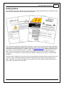
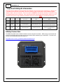
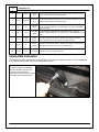
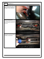
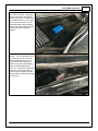
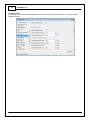
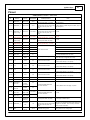
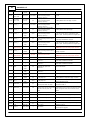
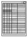
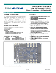
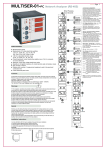
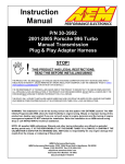
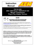
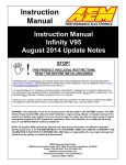
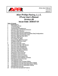
Instruction
Manual
30-3903
2002-2005 VW 1.8T AWP
INFINITY-6/8H*
PnP ADAPTER HARNESS
STOP!
THIS PRODUCT HAS LEGAL RESTRICTIONS.
READ THIS BEFORE INSTALLING/USING!
THIS PRODUCT MAY BE USED SOLELY ON VEHICLES USED IN SANCTIONED COMPETITION WHICH MAY NEVER BE USED UPON A
PUBLIC ROAD OR HIGHWAY, UNLESS PERMITTED BY SPECIFIC REGULATORY EXEMPTION. (VISIT THE “EMISSIONS” PAGE AT HTTP://
WWW.SEMASAN.COM/EMISSIONS FOR STATE BY STATE DETAILS.)
IT IS THE RESPONSIBILITY OF THE INSTALLER AND/OR USER OF THIS PRODUCT TO ENSURE THAT IT IS USED IN COMPLIANCE WITH
ALL APPLICABLE LAWS AND REGULATIONS. IF THIS PRODUCT WAS PURCHASED IN ERROR, DO NOT INSTALL AND/OR USE IT. THE
PURCHASER MUST ARRANGE TO RETURN THE PRODUCT FOR A FULL REFUND.
THIS POLICY ONLY APPLIES TO INSTALLERS AND/OR USERS WHO ARE LOCATED IN THE UNITED STATES; HOWEVER CUSTOMERS
WHO RESIDE IN OTHER COUNTRIES SHOULD ACT IN ACCORDANCE WITH THEIR LOCAL LAWS AND REGULATIONS.
WARNING: This installation is not for the tuning novice! Use this system with EXTREME caution! The AEM
Infinity Programmable EMS allows for total flexibility in engine tuning. Misuse or improper tuning of this
product can destroy your engine! If you are not well versed in engine dynamics and the tuning of engine
management systems DO NOT attempt the installation. Refer the installation to an AEM-trained tuning
shop or call 800-423-0046 for technical assistance.
NOTE: All supplied AEM calibrations, Wizards and other tuning information are offered as potential
starting points only. IT IS THE RESPONSIBILITY OF THE ENGINE TUNER TO ULTIMATELY CONFIRM IF THE
CALIBRATION IS SAFE FOR ITS INTENDED USE. AEM holds no responsibility for any engine damage that
results from the misuse or mistuning of this product!
AEM Performance Electronics
AEM Performance Electronics, 2205 126th Street Unit A, Hawthorne, CA 90250
Phone: (310) 484-2322 Fax: (310) 484-0152
http://www.aemelectronics.com
Instruction Part Number: 10-3903
Document Build 1/6/2015
2
3903-MKIV 1.8T
Overview
The 30-3903 AEM Infinity Adapter kit was designed for 2002-2005 Volkswagen 1.8T Golf/Jetta/GTI cars with AWP
engine code and manual transmission. This is a true standalone system that eliminates the use of the factory
ECU. The kit is “plug and play” so no cutting or splicing is necessary. The base configuration files available for the
Infinity ECU are starting points only and will need to be modified for your specific application. Please read this
document in its entirety before attempting to start or run an engine.
The available AEM Infinity EMS part numbers for this adapter kit are:
30-7106 Infinity-6
30-7108 Infinity-8h**
Suggested additional components:
30-3903-00 Boost-to-MAP Sensor Adapter Harness
30-2130-50 Stainless Steel 3.5Bar MAP Sensor
Important Application Notes
The test vehicle used for development of this app was a 2003 GTI that was mostly stock except for an AEM cold
air intake and 3" cat-less downpipe. The AWP engine does have variable valve control (VVC) on the intake cam
only that appears to only be utilized during cold starts when the secondary air injection pump is active. The
adapter in this kit has been built to give the Infinity cam control, however the base session does not have any VVC
controls configured as advancing the intake cam during dyno testing showed that power was always decreased.
The stock ECU uses mass air flow (MAF) fueling control using a MAF sensor in the intake piping ahead of the
turbo. The Infinity only uses Speed Density fueling control for this application and the MAF sensor is not utilized in
the adapter so the sensor can be removed if desired. The stock ECU references a boost sensor that is located in
the stock side-mount intercooler ahead of the throttle body. Because the Infinity only uses Speed Density fueling
control, a manifold absolute pressure (MAP) sensor input is necessary that is referencing manifold pressure after
the throttle blade. There is an available boost-to-MAP sensor adapter harness available (AEM part number 303903-00) that allows an AEM stainless steel MAP sensor (3.5Bar MAP sensor suggested, PN 30-2130-50) to be
plugged into the stock boost sensor connector making for seamless integration. See MAP sensor installation
instruction further in this manual.
The stock drive-by-wire (DBW) throttle body has been fully characterized and the provided base session is
configured for its use. Larger throttle size DBW throttle bodies may be used however use of those throttle bodies
will require full characterization and PID controls tuning. None of the stock emissions controls (secondary air
injection, EGR, Evap, etc) are supported. Additionally, the N249 bypass valve activation solenoid is also not
supported. The AWP uses a Bosch wideband O2 sensor from the factory which is utilized by the Infinity through
the cars wiring harness thus an additional O2 sensor is not required. Note that the O2 sensor isn't powered by the
car until the engine is running. Cruise control is not supported by the Infinity and the steering wheel cruise control
buttons are not utilized in any way. The cars CAN datastream is supported by the Infinity and allows for the
factory gauges to function correctly as well as the Infinity to reference all four wheel speeds as well as steering
angle.
© 2015 AEM Performance Electronics
Important Application Notes
3
Getting Started
Your Infinity EMS will be packaged with four important documents: Usage Legality Disclaimer, Software Download
Notice, Security Code Notice, and an Infinity Quick Start Guide.
First, read and acknowledge the Usage Legality Disclaimer. Second, refer to the Infinity Quick Start Guide (QSG).
Third, follow the Software Download Notice and download the Infinity Tuner software, wizards, and drivers from the
AEM Electronics web site (section 2.1 in QSG). Fourth, visit www.aeminfinity.com to register your EMS (section
3.2 in QSG). Once the registration process is complete, you'll be able to download the latest firmware for your
EMS. The final setup process is to open the Infinity Tuner software and connect to your EMS to update the
firmware (section 3.3 in QSG). This can be done once the EMS is installed into your vehicle - see Infinity EMS
Installation.
Once the Infinity is installed into your vehicle and it has been loaded with the latest firmware, setup and tuning may
commence. Refer to the QSG for additional information on getting the engine ready for tuning with the Infinity
EMS. Additionally, the full Infinity User Manual can be referenced for more in-depth information pertaining to the
install, setup, and usage of the Infinity EMS.
© 2015 AEM Performance Electronics
4
3903-MKIV 1.8T
**Important Infinity-8h Information
This plug and play adapter kit has specifically been designed to be used with the 30-7106 Infinity-6. While the 307108 Infinity-8h can be used, it will result in the loss of Idle A/C Offset compensation and the additional digital
frequency input in the Aux connector. Pins C1-31 and C1-32 MUST be removed from the 80 pin connector if using
this adapter harness with an Infinity-8h. Also, the Infinity-8h does not have Peak & Hold injector drivers to run low
impedance fuel injectors. High impedance (saturated, high-z) fuel injectors MUST be used with the Infinity-8h.
Infinity
Pin
Infinity-6
Function
Infinity-8h
Function
VW 1.8T Adapter
Pin/Function
Infinity-6
Notes
Infinity-8h
Notes
C1-3
Low side6
Injector7
No Connect/Not Used
Available LS output
Available injector output
C1-4
Low side7
Injector8
No Connect/Not Used
Available LS output
Available injector output
C1-31
Digital6
Coil7
Aux 7/Freq Input
Spare freq input in Aux
Loss of spare freq input, MUST remove
pin from Infinity 80 pin connector
C1-32
Digital7
Coil8
40/A/C Req Sw itch
A/C Req sw itch input
Loss of A/C idle compensation, MUST
remove pin from Infinity 80 pin
connector
Infinity Connectors
The AEM Infinity EMS uses the MX123 Sealed Connection System from Molex. AEM strongly recommends that
users become familiar with the proper tools and procedures before attempting any modifications. The entire user
manual can be downloaded direct from Molex at:
http://www.molex.com/mx_upload/family//MX123UserManual.pdf
© 2015 AEM Performance Electronics
Infinity Connectors
5
Infinity Adapter Harness
The basis of the VW 1.8T Infinity kit is the adapter harness that mates the Infinity ECU with the cars factory wiring
harness. This adapter allows for seamless integration of the Infinity EMS onto your vehicle.
AEMNet is an open architecture based on CAN 2.0 which provides the ability for multiple enabled devices, such as
dashboards, data loggers, etc. to easily communicate with one another through two twisted cables (CAN+/CAN-).
The 2 pin Flash Enable connector is used as a secondary hardware flashing option by jumping the two wires
together using the included shunt connector. Note: Flashing will normally be performed in the software not using
this connector.
Integrated in the 1.8T adapter harness is an “auxiliary” connector. This is a Deutsch DTM 12P connector and is
used to adapt many common ancillary inputs and outputs easily. Included in the kit are a DTM 12P mating
connector, 12 DTM terminals, and a DTM 12P wedgelock. If used, these components will need to be terminated by
the installer or end user with 16-22awg wire (not included). Note: the pin numbering is based on the numbers
molded into the connector.
Deutsch
Pin
Infinity
Pin
Pin
Description
Default Pin
Function
Notes
1
C1-53
Analog 9
Fuel
Pressure
Can be used to monitor fuel pressure for fuel delivery calculation. Use AEM
stainless steel 100psig or 150psig sensor. Connect directly to signal w ire of
pressure sensor. See Setup Wizard. Analog input NOT reassignable.
2
C1-75
Analog 10
Baro
Can be used to monitor barometric pressure. Use AEM stainless steel MAP
sensor. Connect directly to signal w ire of MAP sensor. See Setup Wizard.
Analog input is also reassignable to other functions.
3
C1-74
Analog 11
Shift Sw itch
Can be used to activate Shift Cut for 'no-lift-shifting'. See Setup Wizard.
Analog input is also reassignable to other functions.
4
C1-73
Analog 13
Oil Pressure
Can be used to monitor oil pressure for Engine Protection. See Setup Wizard.
Analog input is also reassignable to other functions.
5
C1-40
Temp 3
Oil Temp
Can be used to monitor oil temperature. See Setup Wizard. Can also be used
to monitor other temp input.
© 2015 AEM Performance Electronics
6
3903-MKIV 1.8T
6
C1-29
Digital 4
Spare Freq
Input
Can be used to measure frequency input such as Flex Fuel Sensor or turbo
speed or w heel speed, etc. See Setup Wizard.
7
C1-31
Digital 6
Spare Freq
Input
Can be used to measure frequency input such as Flex Fuel Sensor or turbo
speed or w heel speed, etc. See Setup Wizard.
8
C1-1
LS 4
Low Side
Output
Can be used as a configurable low side output to control a variety of
functions. Output is pulled up to 12v and rated to 1.7A. Do not use to PWM
high current loads.
9
C1-2
LS 5
Low Side
Output
Can be used as a configurable low side output to control a variety of
functions. Output is pulled up to 12v and rated to 6A. Ok to PWM high current
loads.
10
C1-23
Sensor
Ground
Sensor
Ground
Used as 0v reference for sensors. Do NOT use as pow er or chassis
ground. Connect to sensor ground pins on auxiliary sensors.
11
C1-49
5v
Sensor
Pow er
Used as 5v reference for sensors. Do NOT use to pow er any high current
loads. Connect to sensor pow er pins on auxiliary sensor.
12
C1-63
12v
+12v Pow er Used as 12v pow er for auxiliary devices.
Infinity EMS Installation
The following procedure describes how to remove the plastic cowl that's below the bottom of the windshield and
then install the Infinity EMS using the provided adapter harness.
First, raise the hood and disconnect
the ground cable from the battery.
Remove the plastic cap from the
pivot end of each wiper arm.
Remove the 13mm nut that secures
each wiper arm to its drive shaft.
© 2015 AEM Performance Electronics
Infinity EMS Installation
Remove each wiper arm from its
drive shaft. Removal is usually best
achieved by grasping the wiper arm
immediately below the blade pivot
point and working the wiper arm
away and towards the windshield
repeatedly until the arm comes
loose. The wiper arm mounting hole
is tapered and splined so removal
can be difficult.
Remove the entire rear hood seal by
pulling up on it.
Remove the cabin air filter cover by
removing the four screws and lifting
the cover up while pulling it towards
the front of the car.
© 2015 AEM Performance Electronics
7
8
3903-MKIV 1.8T
Remove the cowl by starting at one
end and pulling the end of the cowl
straight out from the windshield to
disengage it from its retaining clip.
Remove the wiring harness
connectors from the ECU by sliding
the connector locks out to the side
and then pulling the connectors out
of the ECU.
Pry up on metal tabs that are
holding ECU in place using a flat tip
screwdriver. Remove ECU.
© 2015 AEM Performance Electronics
Infinity EMS Installation
The Infinity is to be placed into the
cowl cavity as shown. Thoroughly
clean the area below the EMS to
allow for the velcro to be applied and
then install the EMS. Do not apply
velcro to bottom of EMS or to the
cowl sheet metal until the adapter
harness has been installed and the
location of the EMS has been
finalized.
Carefully install the Infinity adapter
harness. This is most easily done
by inserting the Infinity connector
end of the harness into the cowl
cavity first and then rotating the
harness to the right while passing
under the sheet metal tab that
sticks out. Place the enclosed ECU
connector into the spot where the
stock ECU was originally located
being mindful of metal tabs that may
be sticking up.
© 2015 AEM Performance Electronics
9
10
3903-MKIV 1.8T
Connect the Infinity end of the
harness to the Infinity EMS.
Connect the factory wiring harness
connectors to the overmolded ECU
connector. Ensure that the
connectors are fully seated with
their locks completely pushed in.
With the location of the EMS
finalized, apply velcro the hold the
EMS in place.
Connect the supplied USB comms
cable and USB logging cable to the
Infinity and route as desired.
© 2015 AEM Performance Electronics
Infinity EMS Installation
If using the suggested 30-3903-00
MAP sensor adapter harness,
disconnect the OEM boost sensor
connector. The factory boost
sensor is mounted in the top of the
stock side mount intercooler and is
located behind the passenger side
headlight near the base of the
washer fluid reservoir.
Install AEM MAP sensor by tapping
into manifold pressure reference
line. The example installation has
the MAP sensor tee'd into the fuel
pressure regulator manifold pressure
reference line. Connect the AEM
MAP sensor adapter harness to the
AEM MAP sensor.
© 2015 AEM Performance Electronics
11
12
3903-MKIV 1.8T
Connect the OEM boost sensor
connector to the AEM MAP sensor
adapter harness.
Installation complete. It is suggested to re-connect the battery ground cable and test that the Infinity turns on and
is able to be comm'ed up with with a PC before replacing the plastic cowl. The software should indicate that the
EMS firmware needs to be updated if this is the first time the EMS has been powered on and comm'd up with with
a PC.
Re-installation of plastic cowl is the reverse of removal.
© 2015 AEM Performance Electronics
Infinity EMS Installation
13
Loading Base Session
There is a provided base session that must be loaded into the Infinity EMS before attempting to start or run the
engine. Before the base session can be loaded, the EMS firmware must be updated (section 3.3 in QSG). Once
the process of updating the firmware and loading the base cal has been completed, the setup wizards will need to
be reviewed and the ignition timing will need to be synced.
1. Connect USB comms cable between ECU and PC.
2. Turn ignition switch on.
3. Open InfinityTuner; connection status should be green and indicate ECU type.
4. Open an Infinity layout: Layout>Open Layout. Layout located in My Documents>AEM>Infinity Tuner>Layouts.
5. Upload base session: File>Import Calibration Data. Base session located in My Documents>AEM>Infinity
Tuner>Sessions.
6. After session has loaded, turn ignition switch off, wait for main relay to click off and then turn ignition switch
back on.
7. After comms have been reestablished, review Setup Wizard: Plug-ins>Wizard>Setup Wizard.
Setup Wizard
The follow is an overview of the basic wizard settings that need to be checked before attempting to start and run an
engine. Please refer to the main Infinity user guide for information about the advanced wizard settings.
Basic
Adjust engine displacement is engine is different than stock 1.8L. Not other changes should be necessary.
© 2015 AEM Performance Electronics
14
3903-MKIV 1.8T
Tuning Preferences
If Key Off Commit is selected, the ECU will automatically save any unsaved changes when the ignition power input
(pin C1-48) is turned off. This function could take several seconds to complete. If battery permanent power (pin
C1-10) is removed before this action has completed, the ECU may become inoperable and require reprogramming
at AEM. It is generally recommend that Key Off Commit be used.
Cam/Crank
The correct cam/crank wizard selection is set for VW 1.8T in the base session.
© 2015 AEM Performance Electronics
Setup Wizard
15
Injector Setup/Flow
Verify number of injectors (saturated secondary injectors supported with Infinity-8h) and select Primary Injector
Fuel Type (gasoline, ethanol, methanol, E85, or flex fuel). Injector phasing values are automatically set based on
the firing order selected in the Basic wizard and should not need adjusting. Select the primary injectors being
used in the Primary Injector Flow Wizard. Primary Fuel Pressure Regulator Reference is set to manifold in the
base session.
© 2015 AEM Performance Electronics
16
3903-MKIV 1.8T
Basic Sensors
Set the basic sensors. The stock VW air and coolant temp sensor are set in the base session. The base session
is configured to use an AEM 3.5Bar MAP sensor and 150psi fuel pressure sensor. If using different sensors,
select the appropriate settings.
Idle
The idle activation criteria is set in the base session.
© 2015 AEM Performance Electronics
Setup Wizard
17
Main Rev Limiter
Set desired main rev limiter settings.
Set Throttle Range
DO NOT use the Set Throttle Range wizard! The throttle range is established when the Drive By Wire Wizard is
used.
© 2015 AEM Performance Electronics
18
3903-MKIV 1.8T
Lambda Control
It is generally recommend that lambda feedback not be used during initial VE table tuning. Uncheck Lambda
Feedback Enable.
© 2015 AEM Performance Electronics
Setup Wizard
19
Drive By Wire Wizard
The base calibration will set most of the Drive-By-Wire (DBW) channels for the stock VW 1.8T throttle body. If a
different throttle body is used (R32, Hemi, etc) then further adjustments to the DBW channels may be required. To
complete the DBW setup the Drive By Wire Wizard must be ran.
Select Calibrate sensor data only and follow the DBW Setup steps.
Note: There are a few integrated DBW fail safes incorporated into the Infinity system. For instance, if the
accelerator pedal and throttle position sensors do not track each other, or if the maximum DBW current is
exceeded, there will be a fatal error which will enable the DBW Error Rev Limit (the rev limit is adjustable in the
DBW Tuning section of the Setup Wizard) for safety purposes. This error will reset when the ignition key is cycled
or if the problem is fixed. Additionally, the 1.8T base session is setup with brake override enabled. The Brake
Throttle Override kills the engine if the accelerator and brake pedals are pressed at the same time under certain
conditions.
© 2015 AEM Performance Electronics
20
3903-MKIV 1.8T
Ignition Sync
Proper ignition sync ensures that the commanded timing in the software is actually the ignition timing value
delivered to the engine. For example, when commanding 10° of timing advance in the software, there should be
10° of timing advance at the engine when checked with a timing light. The ignition sync has already been set in
the VW 1.8T base session and should not require adjustment, however, it is always good practice to verify proper
ignition sync.
The 1.8T engine has its ignition timing checked on the flywheel instead of on
the crank pulley. Locate the timing mark viewing hole in the top of the
bellhousing near the back of the cylinder block and remove the access plug.
The air intake tract may need to be temporarily removed in order to gain line of
sight to the timing mark with a timing light.
The correct way to trigger a timing light is to put the inductive pickup on a high
voltage secondary ignition wire. On a coil-on-plug arrangement, this means
removing coil #1 from its well and using a spark plug wire between the coil and
the spark plug. Do not attempt to trigger the timing light off of the low voltage
trigger wires going into the coil. Doing so may cause incorrect readings with
the timing light which may ultimately result in an incorrect ignition sync
adjustment.
Once the Drive By Wire Wizard has been completed, the engine can be
started and idled. In the Setup Wizard, go to the Ignition Sync Wizard. Lock
the timing at a value that can be easily verified. If using a non-dial back timing light, lock the timing at 0°; if using a
dial back timing light, set the timing to a value that will allow the engine to idle easily (10° or 15°, etc) and set the
dial back to the same amount. Check that the timing mark on the flywheel lines up with the pointer in the
bellhousing. If the indicated timing is off from the pointer, use the Advance or Retard Timing buttons in the until the
ignition sync is correct. Unlock the timing once the ignition sync has been verified.
© 2015 AEM Performance Electronics
Ignition Sync
21
Pinout
Infinity-6/8H, P/N 30-7106/7108
Infinity
Pin
Hardware
Reference
VW 1.8T
Function
VW 1.8T
Pin Destination
Hardware Specification
Notes
C1-1
LowsideSwitch_4
Spare LS Out
Aux 8
Lowside switch, 1.7A max, NO
internal f ly back diode. 12v pullup.
C1-2
LowsideSwitch_5
Spare LS Out
Aux 9
Lowside switch, 6A max with internal
f ly back diode. Inductiv e load should See Setup Wizard LowSide Assignment Tables page f or
output assignment.
NOT hav e f ull time power. 12v
pullup.
C1-3
LowsideSwitch_6
(Inf inity -6 Only )
Not used
No connect
Lowside switch, 6A max with internal
f ly back diode. Inductiv e load should
Not used.
NOT hav e f ull time power. No
pullup.
C1-3
Injector 7
(Inf inity -8h Only )
Not used
No connect
For use with high impedance (1015ohms) injectors only , 1.7A max.
Not used.
C1-4
LowsideSwitch_7
(Inf inity -6 Only )
Not used
No connect
Lowside switch, 6A max, NO
internal f ly back diode. No pullup.
Not used.
C1-4
Injector 8
(Inf inity -8h Only )
Not used
No connect
For use with high impedance (1015ohms) injectors only , 1.7A max.
Not used.
C1-5
UEGO 1 Heat
UEGO 1 Heat
5
C1-6
UEGO 1 IA
UEGO 1 IA
71
C1-7
UEGO 1 IP
UEGO 1 IP
52
C1-8
UEGO 1 UN
UEGO 1 UN
70
For on-board wideband Bosch O2 sensor.
C1-9
UEGO 1 VM
UEGO 1 VM
51
For on-board wideband Bosch O2 sensor.
Permanent
Power
62
Dedicated power management CPU
Coil 4
94
25 mA max source current
C1-10 Batt Perm Power
See Setup Wizard LowSide Assignment Tables page f or
output assignment.
For on-board wideband Bosch O2 sensor.
For on-board wideband Bosch O2 sensor.
Bosch UEGO controller
For on-board wideband Bosch O2 sensor.
Full time battery power. MUST be powered bef ore the
ignition switch input is triggered (See C1-48).
Triggers f actory "smart" coils with 5v f alling edge trigger.
C1-11 Coil 4
DO NOT connect directly to coil primary .
Triggers f actory "smart" coils with 5v f alling edge trigger.
C1-12 Coil 3
Coil 3
103
25 mA max source current
DO NOT connect directly to coil primary .
Triggers f actory "smart" coils with 5v f alling edge trigger.
C1-13 Coil 2
Coil 2
95
25 mA max source current
DO NOT connect directly to coil primary .
Triggers f actory "smart" coils with 5v f alling edge trigger.
C1-14 Coil 1
Coil 1
102
25 mA max source current
C1-15 Coil 6
Not used
No connect
25 mA max source current
Not used
C1-16 Coil 5
Not used
No connect
25 mA max source current
Not used
Crank Position
Sensor VR+
Crank
Position
Sensor VR+
82
Crank
Position
Sensor VR-
Dif f erential Variable Reluctance
Zero Cross Detection
See Setup Wizard Cam/Crank page f or options.
Crank Position
C1-18
Sensor VR-
90
Cam Position
Sensor 1 VR-
Cam Position
Sensor 1 VR-
No connect
Cam Position
Sensor 1 VR+
No connect
Dif f erential Variable Reluctance
Zero Cross Detection
Not used.
Cam Position
C1-20
Sensor 1 VR+
Lowside switch, 1.7A max, NO
internal f ly back diode. No pullup.
Disables A/C compressor abov e 80% throttle.
See LS2_Duty % table to adjust.
DO NOT connect directly to coil primary .
C1-17
C1-19
C1-21 LowsideSwitch_2
C1-22 LowsideSwitch_3
C1-23 AGND
A/C
Compressor
WOT Cut
41
Intake Cam
VVC
115
Sensor
Ground
33, 36
© 2015 AEM Performance Electronics
Lowside switch, 6A max with internal
Intake cam VVC supported howev er base session is not
f ly back diode. Inductiv e load should
conf igured f or activ ation. See f ull Inf inity instruction
NOT hav e f ull time power. No
manual f or more inf ormation.
pullup.
Dedicated analog ground
Sensor ground f or 0-5v analog inputs.
22
3903-MKIV 1.8T
C1-24 AGND
Sensor
Ground
91, 99, 108
Dedicated analog ground
Sensor ground f or 0-5v analog inputs.
C1-25
Crank Position
Sensor 1 Hall
Not used
No connect
10K pullup to 12V. Will work with
ground or f loating switches.
Frequency input only .
Not used.
C1-26
Cam Position
Sensor 1 Hall
Cam Position
Sensor
86
10K pullup to 12V. Will work with
ground or f loating switches.
Frequency input only .
See Setup Wizard Cam/Crank page f or options.
C1-27 Digital_In_2
Not used
No connect
10K pullup to 12V. Will work with
ground or f loating switches.
Frequency input only .
Not used.
C1-28 Digital_In_3
Vehicle Speed
Sensor
54
10K pullup to 12V. Will work with
ground or f loating switches.
Frequency input only .
See Setup Wizard Vehicle Speed page.
C1-29 Digital_In_4
Spare
Frequency
Input
Aux 6
10K pullup to 12V. Will work with
ground or f loating switches.
Frequency input only .
Can be used f or Flex Fuel or Turbo Speed or other
f requency input. See Setup Wizard to conf igure input.
C1-30 Digital_In_5
Brake Switch
55
10K pullup to 12V. Will work with
ground or f loating switches. Switch
input only .
Brake switch input f or DBW Brake Throttle Ov erride.
See Driv e By Wire Wizard to conf igure.
C1-31 Digital_In_6
Spare
Frequency
Input
Aux 7
10K pullup to 12V. Will work with
ground or f loating switches.
Frequency input only .
Can be used f or Flex Fuel or Turbo Speed or other
f requency input. See Setup Wizard to conf igure input.
Not used
Not used
25 mA max source current
Not used. Spare Frequency input lost if using Inf inity 8h. MUST remov e pin f rom Inf inity 80 pin connector.
A/C Request
Switch
40
10K pullup to 12V. Will work with
ground or f loating switches. Switch
input only .
Used to activ ate Idle A/C Of f set. See Setup Wizard
Idle page f or options.
Not used
Not used
25 mA max source current
Not used. Idle A/C Of f set f unction lost if using Inf inity 8h. MUST remov e pin f rom Inf inity 80 pin connector.
Ground
2
Power ground
Power ground.
Four pin DTM connector in AEM adapter harness.
Contact AEM f or additional inf ormation.
C1-31
Coil 7
(Inf inity -8h Only )
C1-32 Digital_In_7
C1-32
Coil 8
(Inf inity -8h Only )
C1-33 Power Ground
C1-34 CAN A-
AEMNet CAN-
AEMNet
Dedicated high speed CAN
transceiv er
C1-35 CAN A+
AEMNet CAN
+
AEMNet
Dedicated high speed CAN
transceiv er
Four pin DTM connector in AEM adapter harness.
Contact AEM f or additional inf ormation.
C1-36 CAN B-
Chassis
CANCAN-
58
Dedicated high speed CAN
transceiv er
Used f or VW CAN bus.
C1-37 CAN B+
Chassis
CAN+
60
Dedicated high speed CAN
transceiv er
Used f or VW CAN bus.
C1-38 Temp 1
Coolant Temp
Sensor
93
2.49k pullup to 5v
See Setup Wizard Coolant Temperature page f or options.
C1-39 Temp 2
Air Temp
Sensor
85
2.49k pullup to 5v
See Setup Wizard Air Temperature page f or options.
C1-40 Temp 3
Spare Temp
Input
Aux 5
2.49k pullup to 5v
Can be used f or Oil Temperature input. See Setup
Wizard Oil Temperature page.
C1-41 LowsideSwitch_0
Fuel Pump
65
Lowside switch, 4A max, NO
internal f ly back diode. No pullup.
Switched ground. Will prime f or 2 seconds at key on
and activ ate if RPM > 0.
C1-42 LowsideSwitch_1
Boost Control
104
Lowside switch, 4A max with internal
f ly back diode. Inductiv e load should
NOT hav e f ull time power. No
pullup.
See Setup Wizard Boost Control page f or options.
Monitor BoostControl [%] channel f or output state. Base
session conf igured to driv e stock N75 boost control
solenoid.
Power ground
Power ground.
C1-43 Power Ground
Ground
1
C1-44 Knock Sensor 1
Knock Sensor
1
106
Dedicated knock signal processor
See Setup Wizard Knock Setup page f or options.
C1-45 Knock Sensor 2
Knock Sensor
2
107
Dedicated knock signal processor
See Setup Wizard Knock Setup page f or options.
Ground
1
Power ground
Power ground.
Ground out to
main relay
21
0.7A max ground sink f or external
relay control
Will activ ate at key on and at key of f according to the
conf iguration settings.
Ignition Switch
3
10k pulldown
Full time battery power must be av ailable at C1-10
bef ore this input is triggered.
C1-46 Power Ground
C1-47
Main Relay
Control
C1-48 Ign Switch
© 2015 AEM Performance Electronics
Pinout
23
C1-49 +5V_Out
+5V Sensor
Power
72, 73
Regulated, f used +5V supply f or
sensor power
Analog sensor power.
C1-50 +5V_Out
+5V Sensor
Power
83, 98
Regulated, f used +5V supply f or
sensor power
Analog sensor power.
C1-51 Analog_In_7
DBW TPS1
84
12 bit A/D, 100K pullup to 5V
PnP f or TPS1 input f rom DBW throttle body .
C1-52 Analog_In_8
Boost/MAP
Sensor
101
12 bit A/D, 100K pullup to 5V
MAP input. Use included Boost/MAP sensor adapter
harness.
C1-53 Analog_In_9
Fuel Pressure
Aux 1
12 bit A/D, 100K pullup to 5V
Can be used as a Fuel Pressure input f or f uel deliv ery
calculation. See the Setup Wizard Fuel Pressure page
f or setup and calibration. Monitor the FuelPressure
[psig] channel.
C1-54 VR+_In_2
Not used
No connect
Not used
No connect
Dif f erential Variable Reluctance
Zero Cross Detection
Not used.
C1-55 VR-_In_2
C1-56 VR-_In_3
Not used
No connect
Not used
No connect
Dif f erential Variable Reluctance
Zero Cross Detection
Not used.
C1-57 VR+_In_3
C1-58 HighsideSwitch_0
Not used
No connect
2.6A max, High Side Solid State
Relay
Not used.
C1-59 Stepper_1B
Not used
No connect
Automotiv e, Programmable Stepper
Not used.
Driv er, up to 28V and ±1.4A
C1-60 Stepper_2B
Not used
No connect
Automotiv e, Programmable Stepper
Not used.
Driv er, up to 28V and ±1.4A
118
5.0A max Throttle Control Hbridge
Driv e
PnP DBW throttle control. Base session is conf igured
f or stock DBW TB. Other TB's may be used but will
require setup and characterization. See Driv e By Wire
Wizard.
DBW Throttle
Open
117
5.0A max Throttle Control Hbridge
Driv e
PnP DBW throttle control. Base session is conf igured
f or stock DBW TB. Other TB's may be used but will
require setup and characterization. See Driv e By Wire
Wizard.
+12v
121
12v power f rom main relay
12v power f rom main relay .
Not used.
C1-61 DBW1 Motor-
DBW Throttle
Close
C1-62 DBW1 Motor+
C1-63 +12v
C1-64 Injector 6
Not used
No connect
Peak and hold, 3A max f or Inf inity 6. Saturated injector driv er f or
Inf inity -8h.
C1-65 Injector 5
Not used
No connect
Peak and hold, 3A max f or Inf inity 6. Saturated injector driv er f or
Inf inity -8h.
Not used.
C1-66 Injector 4
Injector 4
88
Peak and hold, 3A max f or Inf inity 6. Saturated injector driv er f or
Inf inity -8h.
Injector 4.
Ground
2
Power ground
Power ground.
Not used
No connect
12v power f rom main relay
Not used.
C1-69 Analog_In_19
DBW APP2
34
12 bit A/D, 100K pullup to 5V
PnP f or Accelerator Pedal Position Sensor 2.
C1-70 Analog_In_18
DBW APP1
35
12 bit A/D, 100K pullup to 5V
PnP f or Accelerator Pedal Position Sensor 1.
C1-71 Analog_In_16
DBW TPS2
92
12 bit A/D, 100K pullup to 5V
PnP f or TPS2 input f rom DBW throttle body .
C1-72 Flash Enable
Flash Enable
Flash Enable
Connector
10k pulldown
Two pin DTM connector in AEM adapter harness. Use
only to f orce EMS into f lash mode if normal f irmware
update procedure does not work.
C1-73 Analog_In_13
Spare Analog
Input
Aux 4
12 bit A/D, 100K pullup to 5V
Can be used as Oil Pressure, Mode Switch, 3-Step or
other analog input. See Oil Pressure or Input Function
Assignments in Setup Wizard.
C1-74 Analog_In_11
Spare Analog
Input
Aux 3
12 bit A/D, 100K pullup to 5V
Can be used as Shif tSwitch, Mode Switch, 3-Step or
other analog input. See Shif t Cut or Input Function
Assignments in Setup Wizard.
C1-75 Analog_In_10
Spare Analog
Input
Aux 2
12 bit A/D, 100K pullup to 5V
Can be used as Barometric Pressure, Mode Switch, 3Step or other analog input. See Barometric Pressure or
Input Function Assignments in Setup Wizard.
C1-67 Power Ground
C1-68 +12v
© 2015 AEM Performance Electronics
24
3903-MKIV 1.8T
C1-76 Injector 3
Injector 3
97
Peak and hold, 3A max f or Inf inity 6. Saturated injector driv er f or
Inf inity -8h.
Injector 3.
C1-77 Injector 2
Injector 2
89
Peak and hold, 3A max f or Inf inity 6. Saturated injector driv er f or
Inf inity -8h.
Injector 2.
C1-78 Injector 1
Injector 1
96
Peak and hold, 3A max f or Inf inity 6. Saturated injector driv er f or
Inf inity -8h.
Injector 1.
C1-79 Stepper_2A
Not used
No connect
Automotiv e, Programmable Stepper
Not used.
Driv er, up to 28V and ±1.4A
C1-80 Stepper_1A
Not used
No connect
Automotiv e, Programmable Stepper
Not used.
Driv er, up to 28V and ±1.4A
12 MONTH LIMITED WARRANTY
Advanced Engine Management Inc. warrants to the consumer that all AEM High Performance
products will be free from defects in material and workmanship for a period of twelve (12)
months from date of the original purchase. Products that fail within this 12-month warranty period
will be repaired or replaced at AEM’s option, when determined by AEM that the product failed
due to defects in material or workmanship. This warranty is limited to the repair or replacement
of the AEM part. In no event shall this warranty exceed the original purchase price of the AEM
part nor shall AEM be responsible for special, incidental or consequential damages or cost
incurred due to the failure of this product. Warranty claims to AEM must be transportation
prepaid and accompanied with dated proof of purchase. This warranty applies only to the
original purchaser of product and is non-transferable. All implied warranties shall be limited in
duration to the said 12-month warranty period. Improper use or installation, accident, abuse,
unauthorized repairs or alterations voids this warranty. AEM disclaims any liability for
consequential damages due to breach of any written or implied warranty on all products
manufactured by AEM. Warranty returns will only be accepted by AEM when accompanied by a
valid Return Merchandise Authorization (RMA) number. Product must be received by AEM
within 30 days of the date the RMA is issued.
Please note that before AEM can issue an RMA for any electronic product, it is first necessary
for the installer or end user to contact the EMS tech line at 1-800-423-0046 to discuss the
problem. Most issues can be resolved over the phone. Under no circumstances should a
system be returned or a RMA requested before the above process transpires.
AEM will not be responsible for electronic products that are installed incorrectly, installed in a
non-approved application, misused, or tampered with.
Any AEM electronics product can be returned for repair if it is out of the warranty period. There is
a minimum charge of $50.00 for inspection and diagnosis of AEM electronic parts. Parts used in
the repair of AEM electronic components will be extra. AEM will provide an estimate of repairs
and receive written or electronic authorization before repairs are made to the product.
© 2015 AEM Performance Electronics