1
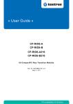
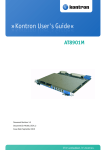
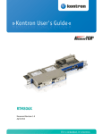
» Kontron User's Guide «
CP-RIO6-923-F
Document Revision 1.1
Document ID: CP-RIO6-923-F
Issue Date: April 2011
If it's embedded,
it's Kontron.
www.kontron.com
Revision History
Rev. Index
Brief Description of Changes
Date of Issue
0.5
Initial Issue
29.09.2009
1.0
Frontplate drawing updated
01.10.2009
1.1
Minor changes in chapter 1. Section „M12 100BASE-TX Ports“ added in
chapter 3 and other minor changes.
27.04.2011
Customer Service
Contact Information:
Kontron Canada, Inc.
4555 Ambroise-Lafortune
Boisbriand, Québec, Canada
J7H 0A4
Tel: (450) 437-5682
(800) 354-4223
Fax: (450) 437-8053
E-mail: [email protected]
Kontron Modular Computer GmbH
Sudetenstrasse 7
87600 Kaufbeuren
Germany
+49 (0) 8341 803 333
+49 (0) 8341 803 339
[email protected]
Visit our site at:www.kontron.com
© 2011 Kontron, an International Corporation. All rights reserved.
The information in this user's guide is provided for reference only. Kontron does not assume any liability
arising out of the application or use of the information or products described herein. This user's guide may
contain or reference information and products protected by copyrights or patents and does not convey any
license under the patent rights of Kontron, nor the rights of others.
Kontron is a registered trademark of Kontron. All trademarks, registered trademarks, and trade names used
in this user's guide are the property of their respective owners. All rights reserved. Printed in Canada. This
user's guide contains information proprietary to Kontron. Customers may reprint and use this user's guide
in other publications. Customers may alter this user's guide and publish it only after they remove the Kontron name, cover, and logo.
Kontron reserves the right to make changes without notice in product or component design as warranted by
evolution in user needs or progress in engineering or manufacturing technology. Changes that affect the
operation of the unit will be documented in the next revision of this user's guide.
ii
CP-RIO6-923-F User Guide
www.kontron.com
Table of Contents
Revision History .................................................................................................................. ii
Customer Service ................................................................................................................ ii
Proprietary Note .................................................................................................................vi
Trademarks ......................................................................................................................vi
Environmental Protection Statement .......................................................................................vi
Before you Begin ...............................................................................................................vii
When Working Inside a Computer ..........................................................................................viii
Advisory Conventions ...........................................................................................................ix
Safety Instructions .............................................................................................................. x
Special Handling and Unpacking Instructions ............................................................................xi
General Instructions on Usage ..............................................................................................xii
Regulatory Compliance Statements .......................................................................................xiii
Two Year Warranty ............................................................................................................. xiv
1
Introduction ...................................................................................................2
1.1 Product Overview .........................................................................................2
1.2 Technical Specification .................................................................................3
2
Installation ....................................................................................................5
2.1 Safety Requirements ....................................................................................5
2.2 Installation Procedure ..................................................................................6
2.3 Removal Procedure ......................................................................................7
3
Hardware Description .......................................................................................9
3.1 RJ45 1000BASE-T Ports .................................................................................9
3.2 M12 100BASE-TX Ports ................................................................................ 10
3.3 CompactPCI Bus Connectors ......................................................................... 11
3.4 Air Baffle ................................................................................................. 15
3.5 Front Panel Elements .................................................................................. 15
A
Getting Help ................................................................................................. A-2
A.1 Returning Defective Merchandise............................................................................. A-2
A.2 When Returning a Unit.......................................................................................... A-3
iii
CP-RIO6-923 User Guide
www.kontron.com
List of Tables
Table 1-1
Table 3-1
Table 3-2
Table 3-3
Table 3-4
Table 3-5
Table 3-6
Table 3-7
CP-RIO6-923-F Main Specifications ................................................................ 3
Ethernet Port Mapping ............................................................................... 9
RJ45 Pin Assignment ................................................................................ 10
Ethernet Port Mapping .............................................................................. 10
M12 D-coded female Connector Pin Assignment ............................................... 11
J3 Connector Pin Assignment ...................................................................... 12
J4 Connector Pin Assignment ...................................................................... 13
J5 Connector Pin Assignment ...................................................................... 14
iv
CP-RIO6-923-F User Guide
www.kontron.com
List of Figures
Figure 3-1: CP-RIO6-923-F Front Panel ........................................................................ 15
Figure 3-2: CP-RIO6-923-F12 Front Panel ..................................................................... 15
Figure 3-3: CP-RIO6-923-F-8M12 Front Panel ................................................................ 15
v
CP-RIO6-923-F User Guide
www.kontron.com
Preface
Proprietary Note
This document contains information proprietary to Kontron AG. It may not be copied or transmitted by any
means, disclosed to others, or stored in any retrieval system or media without the prior written consent of
Kontron AG or one of its authorized agents.
The information contained in this document is, to the best of our knowledge, entirely correct. However, Kontron AG cannot accept liability for any inaccuracies or the consequences thereof, or for any liability arising
from the use or application of any circuit, product, or example shown in this document.
Kontron AG reserves the right to change, modify, or improve this document or the product described herein,
as seen fit by Kontron AG without further notice.
Trademarks
Kontron AG and the Kontron logo are trade marks owned by Kontron AG, Germany. In addition, this document
may include names, company logos and trademarks, which are registered trademarks and, therefore, proprietary to their respective owners.
Environmental Protection Statement
This product has been manufactured to satisfy environmental protection requirements where possible. Many
of the components used (structural parts, printed circuit boards, connectors, batteries, etc.) are capable of
being recycled.
Final disposition of this product after its service life must be accomplished in accordance with applicable
country, state, or local laws or regulations.
vi
CP-RIO6-923-F User Guide
www.kontron.com
Preface
Before you Begin
Before handling the board, read the instructions and safety guidelines on the following pages to prevent
damage to the product and to ensure your own personal safety. Refer to the "Advisory Conventions" section
for advisory conventions used in this user's guide, including the distinction between Warnings, Cautions and
Notes.
• Always use caution when handling/operating the computer. Only qualified, experienced, authorized
electronics service personnel should access the interior of the computer. The power supplies produce
high voltages and energy hazards, which can cause bodily harm.
• Use extreme caution when installing or removing components. Refer to the installation instructions in
this user's guide for precautions and procedures. If you have any questions, please contact Kontron
Technical Support
WARNING
High voltages are present inside the chassis when the unit’s power
cord is plugged into an electrical outlet. Turn off system power, turn
off the power supply, and then disconnect the power cord from its
source before removing the chassis cover. Turning off the system
power switch does not remove power to components.
vii
CP-RIO6-923-F User Guide
www.kontron.com
Preface
When Working Inside a Computer
Before taking covers off a computer, perform the following steps:
• Turn off the computer and any peripherals.
• Disconnect the computer and peripherals from power sources or subsystems to prevent electric shock
or system board damage. This does not apply to when hot-swapping parts.
• Disconnect telephone or telecommunications lines from the computer.
In addition, take note of these safety guidelines when appropriate:
• To help avoid possible damage to system boards, wait five seconds after turning off the computer before removing a component, removing a system board, or disconnecting a peripheral device from the
computer.
When you disconnect a cable, pull on its connector or on its strain-relief loop, not on the cable itself. Some
cables have a connector with locking tabs. If you are disconnecting this type of cable, press in on the locking
tabs before disconnecting the cable. As you pull connectors apart, keep them evenly aligned to avoid bending any connector pins. Also, before connecting a cable, make sure both connectors are correctly oriented
and aligned.
CAUTION
Do not attempt to service the system yourself, except as explained in
this user’s guide. Follow installation and troubleshooting instructions closely.
viii
CP-RIO6-923-F User Guide
www.kontron.com
Preface
Advisory Conventions
CAUTION
This symbol and title indicate potential damage to hardware and tells
you how to avoid the problem.
CAUTION
Electric Shock
This symbol and title warn of hazards due to electrical shocks (> 60V)
when touching products or parts of them. Failure to observe the precautions indicated and/or prescribed by the law may endanger your
life/health and/or result in damage to your material.
WARNING
This symbol and title emphasize points which, if not fully understood
and taken into consideration by the reader, may endanger your
health and/or result in damage to your material.
ESD Sensitive Device
This symbol and title inform that electronic boards and their components are sensitive to static electricity. Therefore, care must be taken during all handling operations and inspections of this product, in order to ensure product integrity at all
times.
Please read also the section “Special Handling and Unpacking Instructions”.
Note...
This symbol and title emphasize aspects the reader should read through carefully
for his or her own advantage.
CE Conformity
This symbol indicates that the product described in this manual is in compliance
with all applied CE standards. Please refer also to the section „Regulatory cpmpliance Statements“ in this manual.
ix
CP-RIO6-923-F User Guide
www.kontron.com
Preface
Safety Instructions
Your new Kontron product was developed and tested carefully to provide all features necessary to ensure its
compliance with electrical safety requirements. It was also designed for a long fault-free life. However, the
life expectancy of your product can be drastically reduced by improper treatment during unpacking and
installation. Therefore, in the interest of your own safety and of the correct operation of your new Kontron
product, you are requested to conform with the following guidelines.
WARNING
All operations on this device must be carried out by sufficiently
skilled personnel only.
WARNING
Do not connect a switch port to a telephone line.
WARNING
For installation in a Hot-Plug system, observe the safety instructions
specific to the system. Read the relevant documentation.
CAUTION
Electric Shock
High voltages are present inside the chassis when the unit’s power
cord is plugged into an electrical outlet. Turn off system power, turn
off the power supply, and then disconnect the power cord from its
source before removing the chassis cover. Turning off the system
power switch does not remove power to components.
x
CP-RIO6-923-F User Guide
www.kontron.com
Preface
Special Handling and Unpacking
Instructions
ESD Sensitive Device
This symbol and title inform that electronic boards and their components are sensitive to static electricity. Therefore, care must be taken during all handling operations and inspections of this product, in order to ensure product integrity at all
times.
Unpacking
Follow these recommendations while unpacking:
• Remove all items from the box. If any items listed on the purchase order are missing, notify Kontron
customer service immediately.
• Inspect the product for damage. If there is damage, notify Kontron customer service immediately.
• Keep all the original packaging material for future storage or warranty shipments. If it is necessary to
store or ship the board please re-pack it as nearly as possible in the manner in which it was delivered.
Do not handle this product out of its protective enclosure while it is not used for operational purposes unless
it is otherwise protected.
Whenever possible, unpack or pack this product only at EOS/ESD safe work stations. Where a safe work station is not guaranteed, it is important for the user to be electrically discharged before touching the product
with his/her hands or tools. This is most easily done by touching a metal part of your system housing.
It is particularly important to observe standard anti-static precautions when changing mezzanines, ROM
devices, jumper settings etc. If the product contains batteries for RTC or memory back-up, ensure that the
board is not placed on conductive surfaces, including anti-static plastics or sponges. They can cause short
circuits and damage the batteries or conductive circuits on the board.
Powering up the System
Before any installation or setup, ensure that the board is unplugged from power sources or subsystems.
If you encounter a problem, verify the following items:
• Make sure that all connectors are properly connected.
• Verify your boot devices.
• If the system does not start properly, try booting without any other I/O peripherals attached, including
AMC adapters.
xi
CP-RIO6-923-F User Guide
www.kontron.com
Preface
Make sure your system provides the minimum DC voltages required at the board's slot, especially if DC power
is carried by cables.
If you are still not able to get your board running, contact our Technical Support for assistance.
Storing the Boards
Electronic boards are sensitive devices. Do not handle or store device near strong electrostatic, electromagnetic, magnetic or radioactive fields.
General Instructions on Usage
In order to maintain Kontron’s product warranty, this product must not be altered or modified in any way.
Changes or modifications to the device, which are not explicitly approved by Kontron AG and described in
this manual or received from Kontron’s Technical Support as a special handling instruction, will void your
warranty.
This device should only be installed in or connected to systems that fulfill all necessary technical and specific environmental requirements. This applies also to the operational temperature range of the specific
board version, which must not be exceeded. If batteries are present their temperature restrictions must be
taken into account.
xii
CP-RIO6-923-F User Guide
www.kontron.com
Preface
Regulatory Compliance Statements
FCC Compliance Statement for Class B Devices
This equipment has been tested and found to comply with the limits for a Class B digital device, pursuant to
Part 15 of the FCC Rules. These limits are designed to provide reasonable protection against harmful interference in a residential installation. This equipment generated, uses and can radiate radio frequency energy
and, if not installed and used in accordance with the instructions may cause harmful interference to radio
communications. However, there is no guarantee that interference will not occur in a particular installation.
If this equipment does cause harmful interference to radio or television reception, which can be determined
by turning the equipment off and on, the user is encouraged to try to correct the interference by one or more
of the following measures:
• Reorient or relocate the receiving antenna.
• Increase the separation between the equipment and receiver.
• Connect the equipment into an outlet on a circuit different from that to which the receiver is connected.
• Consult the dealer or an experience radio/TV technician for help.
WARNING
This is a Class B product. If not installed in a properly shielded enclosure and used in accordance with this User's Guide, this product may
cause radio interference in which case users may need to take additional measures at their own expense.
Safety Certification
All Kontron equipment meets or exceeds safety requirements based on the IEC/EN/UL/CSA 60950-1 family of
standards entitled, "Safety of information technology equipment." All components are chosen to reduce
fire hazards and provide insulation and protection where necessary. Testing and reports when required are
performed under the international IECEE CB Scheme. Please consult the "Kontron Safety Conformity Policy
Guide" for more information.
CE Certification
The product described in this user's guide was tested in a representative system and is found to be compliant
with the CE marking requirements. For computer systems to remain CE compliant, only CE-compliant parts
may be used. Maintaining CE compliance also requires proper cable and cabling techniques. Although Kontron offers accessories, the customer must ensure that these products are installed with proper shielding to
maintain CE compliance. Kontron does not offer engineering services for designing cabling systems. In
addition, Kontron will not retest or recertify systems or components that have been reconfigured by customers.
xiii
CP-RIO6-923-F User Guide
www.kontron.com
Preface
Two Year Warranty
Kontron AG grants the original purchaser of Kontron’s products a TWO YEAR LIMITED HARDWARE WARRANTY as
described in the following. However, no other warranties that may be granted or implied by anyone on
behalf of Kontron are valid unless the consumer has the express written consent of Kontron AG.
Kontron AG warrants their own products, excluding software, to be free from manufacturing and material
defects for a period of 24 consecutive months from the date of purchase. This warranty is not transferable
nor extendible to cover any other users or long-term storage of the product. It does not cover products
which have been modified, altered or repaired by any other party than Kontron Modular Computers GmbH or
their authorized agents. Furthermore, any product which has been, or is suspected of being damaged as a
result of negligence, improper use, incorrect handling, servicing or maintenance, or which has been damaged as a result of excessive current/voltage or temperature, or which has had its serial number(s), any
other markings or parts thereof altered, defaced or removed will also be excluded from this warranty.
If the customer’s eligibility for warranty has not been voided, in the event of any claim, he may return the
product at the earliest possible convenience to the original place of purchase, together with a copy of the
original document of purchase, a full description of the application the product is used on and a description
of the defect. Pack the product in such a way as to ensure safe transportation (see our safety instructions).
Kontron provides for repair or replacement of any part, assembly or sub-assembly at their own discretion, or
to refund the original cost of purchase, if appropriate. In the event of repair, refunding or replacement of
any part, the ownership of the removed or replaced parts reverts to Kontron Modular Computers GmbH, and
the remaining part of the original guarantee, or any new guarantee to cover the repaired or replaced items,
will be transferred to cover the new or repaired items. Any extensions to the original guarantee are considered gestures of goodwill, and will be defined in the “Repair Report” issued by Kontron with the repaired or
replaced item.
Kontron Modular Computers GmbH will not accept liability for any further claims resulting directly or indirectly from any warranty claim, other than the above specified repair, replacement or refunding. In particular, all claims for damage to any system or process in which the product was employed, or any loss incurred
as a result of the product not functioning at any given time, are excluded. The extent of Kontron Modular
Computers GmbH liability to the customer shall not exceed the original purchase price of the item for which
the claim exists.
Kontron Modular Computers GmbH issues no warranty or representation, either explicit or implicit, with
respect to its products’ reliability, fitness, quality, marketability or ability to fulfil any particular application
or purpose. As a result, the products are sold “as is,” and the responsibility to ensure their suitability for any
given task remains that of the purchaser. In no event will Kontron be liable for direct, indirect or consequential damages resulting from the use of our hardware or software products, or documentation, even if Kontron
were advised of the possibility of such claims prior to the purchase of the product or during any period since
the date of its purchase.
Please remember that no Kontron Modular Computers GmbH employee, dealer or agent is authorized to make
any modification or addition to the above specified terms, either verbally or in any other form, written or
electronically transmitted, without the company’s consent.
xiv
CP-RIO6-923-F User Guide
www.kontron.com
Chapter 1
Introduction
1
www.kontron.com
Introduction
1
Introduction
1.1
Product Overview
The CP-RIO6-923-F, CP-RIO6-923-F12 and CP-RIO6-923-F-8M12 (hereinafter all generally referred to as CPRIO6-923-F) are a family of PICMG 2.0 compliant 6U rear panel I/O board that can be used with PICMG 2.16
compliant switches like the CP6923 or CP6930. They provide access to up to 24 of the switch ports connected
over a one-to-one backplane.
This module is intended to access the backplane ports of a PICMG 2.16 compliant switch board directly. These
are the ports located on connectors J3, J4 and J5. Any connections on the backplane on these connectors
between the switch and any other board are not usable together with the RIO module. However, if no other
boards connect to J3, J4 and J5, but the backplane provides slot interconnection and RIO support, the CPRIO6-923-F can be used without restrictions.
WARNING
If the CP-RIO6-923-F is used with a backplane that supports slot
interconnect on J3 to J5 as well as RIO support, make sure that no
other board in the system connects to J3 to J5. Otherwise, unpredictable behaviour or even damage may occur.
The CP-RIO6-923-F is a rugged design intended to be used in harsh environments and features
• Support of extended temperature range
• Optional conformal coating
• High shock & vibration capabilities
Three variants are available, providing different numbers and types of Ethernet ports:
• CP-RIO6-923-F: Dual-slot (8HP) width, with 24 1000Base-T RJ45 Ethernet ports
• CP-RIO6-923-F12: Single-slot (4HP) width, with 12 1000Base-T RJ45 Ethernet ports
• CP-RIO6-923-F-8M12: Single-slot (4HP) width, with 8 100Base-TX Industrial M12 Ethernet ports
2
CP-RIO6-923-F User Guide
www.kontron.com
Introduction
1.2
Table 1-1:
Technical Specification
CP-RIO6-923-F Main Specifications
CP-RIO6-923-F
SPECIFICATIONS
• 6U CompactPCI, Front-panel I/O board
• 233 mm x 160 mm
Mechanical
Temperature
• Weight:
• CP-RIO6-923-F: 380g
• CP-RIO6-923-F12: 320g
• CP-RIO6-923-F-8M12: 400g
• Operating: -40°C to +85°C
Designed to meet or exceed the following:
Humidity
• Bellcore GR63, Section 4.1
• Operating: 15%-90% (non-condensing) at 55°C (131°F)
• Non-Operating: 5%-95% (non-condensing) at 40°C (104°F)
Designed to meet or exceed the following:
Altitude
• Operating: 4000 m (13123ft)
• Non-operating: 15000 m (49212 ft)
Designed to meet or exceed the following:
Vibration
• Bellcore GR-63, Section 4.4
• Operating: 2gRMS, 1.0G, 5-500Hz each axis
• Non-operating: 0.5G, 5-50Hz, 3.0G, 50-500Hz each axis
Designed to meet or exceed the following:
Shock
• DIN/IEC 60068-2-27
• MIL-STD-810E, Method 516
• 30G, half-sine 11ms, each axis
Designed to meet or exceed the following:
Safety
• UL 60950-1
• EN 60950
Designed to meet or exceed the following:
EMC
• FCC 47 CFR Part 15, Subpart B
• EN55022, EN55024
• EN 300 386
MTBF according to Bellcore Issue 6 (Ground Benign 40°C) is
Reliability
• CP-RIO6-923-F: > 2,621,000 hours
• CP-RIO6-923-F12: > 2,431,000 hours
• CP-RIO6-923-F-8M12: > 2,397,000 hours
3
CP-RIO6-923-F User Guide
www.kontron.com
Chapter 2
Installation
4
www.kontron.com
Installation
2
Installation
The CP-RIO6-923-F has been designed for easy installation. However, the following standard precautions,
installation procedures, and general information must be observed to ensure proper installation and to preclude damage to the board, other system components, or injury to personnel.
2.1
Safety Requirements
The following safety precautions must be observed when installing or operating the CP-RIO6-923-F. Kontron
assumes no responsibility for any damage resulting from failure to comply with these requirements.
ESD Sensitive Device
This CompactPCI board contains electrostatically sensitive devices. Please
observe the necessary precautions to avoid damage to your board:
• Discharge your clothing before touching the assembly. Tools must be discharged before use.
• When unpacking a static-sensitive component from its shipping carton, do
not remove the component's antistatic packing material until you are ready
to install the component in a computer. Just before unwrapping the antistatic packaging, be sure you are at an ESD workstation or grounded. This
will discharge any static electricity that may have built up in your body.
• When transporting a sensitive component, first place it in an antistatic container or packaging.
• Handle all sensitive components at an ESD workstation. If possible, use antistatic floor pads and workbench pads.
• Handle components and boards with care. Do not touch the components or
contacts on a board. Hold a board by its edges or by its metal mounting
bracket.
• Do not handle or store system boards near strong electrostatic, electromagnetic, magnetic, or radioactive fields.
5
CP-RIO6-923-F User Guide
www.kontron.com
Installation
2.2 Installation Procedure
For installing the CP-RIO6-923-F, it is not required that the system is powered down or the switch board in
the corresponding front slot is removed or deactivated. To install the RIO module in a system proceed as follows:
1. Ensure that the safety requirements indicated in section 2.1 are observed.
WARNING
Failure to comply with the instruction below may cause damage to
the board or result in improper system operation.
WARNING
Care must be taken when applying the procedures below to ensure
that neither the CP-RIO6-923-F nor other system boards are physically damaged by the application of these procedures.
2. Carefully insert the board into the slot designated by the application requirements for the board until
it makes contact with the backplane connectors.
WARNING
DO NOT push the board into the backplane connectors. Use the ejector handles to seat the board into the backplane connectors.
3. Using both ejector handles, engage the board with the backplane. When the ejector handles are locked,
the board is engaged.
4. Fasten the front panel retaining screws.
5. Connect all external interfacing cables to the board as required.
6. Ensure that the board and all required interfacing cables are properly secured.
6
CP-RIO6-923-F User Guide
www.kontron.com
Installation
2.3 Removal Procedure
For removing the CP-RIO6-923-F, it is not required that the system is powered down or the switch board in
the corresponding front slot is removed or deactivated. To remove the RIO module proceed as follows:
1. Ensure that the safety requirements indicated in section 2.1 are observed.
WARNING
Care must be taken when applying the procedures below to ensure
that neither the CP-RIO6-923-F nor system boards are physically
damaged by the application of these procedures.
2. Disconnect any interfacing cables that may be connected to the board.
3. Unscrew the front panel retaining screws.
4. Disengage the board from the backplane by first unlocking the board ejection handles and then by
pressing the handles as required until the board is disengaged.
5. After disengaging the board from the backplane, pull the board out of the slot.
6. Dispose of the board as required.
7
CP-RIO6-923-F User Guide
www.kontron.com
Chapter 3
Hardware Description
8
www.kontron.com
Hardware Description
3
Hardware Description
This chapter describes the board specific features of the CP-RIO6-923-F. The building blocks are:
• Ethernet ports
• CompactPCI bus connectors
The module does not require a power supply. There are no active components on the board.
3.1
RJ45 1000BASE-T Ports
On the RJ45 variants, three Integrated Connector Modules (network magnetics + RJ45) are the physical
interface for the 10/100/1000Base-T ports, there are three 2x4 modules on the CP-RIO6-923-F and three
1x4 modules on the CP-RIO6-923-F12.
The CP-RIO6-923-F supports PICMG 2.16 backplane ports FL1 to FL23 and FLf (Fabric to Fabric Link Port). The
CP-RIO6-923-F12 supports FL1 to FL12. The switch interfaces which are accessible via the module are listed
in the following table.
Table 3-1:
Ethernet Port Mapping
PICMG 2.16 Backplane Port
CP-RIO6-923-F Port Label
CP-RIO6-923-F12 Port Label
FL_f
Fx
-
FL_01
1x
1x
FL_02
2x
2x
FL_03
3x
3x
FL_04
4x
4x
FL_05
5x
5x
FL_06
6x
6x
FL_07
7x
7x
FL_08
8x
8x
FL_09
9x
9x
FL_10
10x
10x
FL_11
11x
11x
FL_12
12x
12x
FL_13
13x
-
FL_14
14x
-
FL_15
15x
-
FL_16
16x
-
FL_17
17x
-
FL_18
18x
-
FL_19
19x
-
FL_20
20x
-
FL_21
21x
-
FL_22
22x
-
FL_23
23x
-
9
CP-RIO6-923-F User Guide
www.kontron.com
Hardware Description
Note that ports marked with a „-“ are not available at the module.
The RJ45 connectors are not equipped with LEDs for displaying the link status or activity. These are on the
switch board front panel.
The next table shows the pin assignment of one 10/100/1000BASE-T RJ45 connector.
Table 3-2:
RJ45 Pin Assignment
Signal
Pin
BI_DB+
1
BI_DB-
2
BI_DA+
3
BI_DD+
4
BI_DD-
5
BI_DA-
6
BI_DC+
7
BI_DC-
8
3.2 M12 100BASE-TX Ports
The CP-RIO6-923-F-8M12 supports 100Base-TX operation on eight Industrial M12 D-coded female connectors on the front panel. There is a separate magnetics device for each port.
The module supports PICMG 2.16 backplane ports FL12 to FL19. The switch interfaces which are accessible via
the CP-RIO6-923-F-8M12 are listed in the following table.
Table 3-3:
Ethernet Port Mapping
PICMG 2.16 Backplane Port
CP-RIO6-923-F-8M12 Port Label
FL_12
12x
FL_13
13x
FL_14
14x
FL_15
15x
FL_16
16x
FL_17
17x
FL_18
18x
FL_19
19x
The RJ45 connectors are not equipped with LEDs for displaying the link status or activity. These are on the
switch board front panel.
10
CP-RIO6-923-F User Guide
www.kontron.com
Hardware Description
The table below shows the pin assignment of one M12 D-coded female connector.
Table 3-4:
Pin
M12 D-coded Female Connector Pin Assignment
Signal
1
TD+
2
RD+
3
TD-
4
RD-
Housing
Shield
Industrial Ethernet M12
3.3 CompactPCI Bus Connectors
Three daughter card connecters (rJ3, rJ4 and rJ5) are used for the connection between the CP-RIO6-923-F
and the backplane.
• rJ3 connects FL Port 1 to FL Port 8 and FL Port f
• rJ4 connects FL Port 20 to FL Port 23
• rJ5 connects FL Port 9 to FL Port 19
Connector rJ3 is not implemented on the CP-RIO6-923-F-8M12.
11
CP-RIO6-923-F User Guide
www.kontron.com
Hardware Description
The cPCI connectors have the following pin assignment.
Table 3-5:
Pin
J3 Connector Pin Assignment
Row A
Row B
Row C
Row D
Row E
Row F
19
NC
NC
NC
NC
NC
GND
18
FL_DA24_f+
FL_DA24_f-
GND
FL_DC24_f+
FL_DC24_f-
GND
17
FL_DB24_f+
FL_DB24_f-
GND
FL_DD24_f+
FL_DD24_f-
GND
16
FL_DA8+
FL_DA8-
GND
FL_DC8+
FL_DC8-
GND
15
FL_DB8+
FL_DB8-
GND
FL_DD8+
FL_DD8-
GND
14
FL_DA7+
FL_DA7-
GND
FL_DC7+
FL_DC7-
GND
13
FL_DB7+
FL_DB7-
GND
FL_DD7+
FL_DD7-
GND
12
FL_DA6+
FL_DA6-
GND
FL_DC6+
FL_DC6-
GND
11
FL_DB6+
FL_DB6-
GND
FL_DD6+
FL_DD6-
GND
10
FL_DA5+
FL_DA5-
GND
FL_DC5+
FL_DC5-
GND
9
FL_DB5+
FL_DB5-
GND
FL_DD5+
FL_DD5-
GND
8
FL_DA4+
FL_DA4-
GND
FL_DC4+
FL_DC4-
GND
7
FL_DB4+
FL_DB4-
GND
FL_DD4+
FL_DD4-
GND
6
FL_DA3+
FL_DA3-
GND
FL_DC3+
FL_DC3-
GND
5
FL_DB3+
FL_DB3-
GND
FL_DD3+
FL_DD3-
GND
4
FL_DA2+
FL_DA2-
GND
FL_DC2+
FL_DC2-
GND
3
FL_DB2+
FL_DB2-
GND
FL_DD2+
FL_DD2-
GND
2
FL_DA1+
FL_DA1-
GND
FL_DC1+
FL_DC1-
GND
1
FL_DB1+
FL_DB1-
GND
FL_DD1+
FL_DD1-
GND
12
CP-RIO6-923-F User Guide
www.kontron.com
Hardware Description
Table 3-6:
Pin
J4 Connector Pin Assignment
Row A
Row B
Row C
Row D
Row E
Row F
25
FL_DA20+
FL_DA20-
GND
FL_DC20+
FL_DC20-
GND
24
FL_DB20+
FL_DB20-
GND
FL_DD20+
FL_DD20-
GND
23
FL_DA21+
FL_DA21-
GND
FL_DC21+
FL_DC21-
GND
22
FL_DB21+
FL_DB21-
GND
FL_DD21+
FL_DD21-
GND
21
FL_DA22+
FL_DA22-
GND
FL_DC22+
FL_DC22-
GND
20
FL_DB22+
FL_DB22-
GND
FL_DD22+
FL_DD22-
GND
19
FL_DA23+
FL_DA23-
GND
FL_DC23+
FL_DC23-
GND
18
FL_DB23+
FL_DB23-
GND
FL_DD23+
FL_DD23-
GND
17
NC
NC
NC
NC
NC
GND
16
NC
NC
NC
NC
NC
GND
15
NC
NC
NC
NC
NC
GND
14
13
Key Area
12
11
NC
NC
NC
NC
NC
GND
10
NC
NC
NC
NC
NC
GND
9
NC
NC
NC
NC
NC
GND
8
NC
NC
NC
NC
NC
GND
7
NC
NC
NC
NC
NC
GND
6
NC
NC
NC
NC
NC
GND
5
NC
NC
NC
NC
NC
GND
4
NC
NC
NC
NC
NC
GND
3
NC
NC
NC
NC
NC
GND
2
NC
NC
NC
NC
NC
GND
1
NC
NC
NC
NC
NC
GND
Note...
On the CP-RIO6-923-F-8M12, rJ4 has no connections at all and is only provided
for mechanical stability.
13
CP-RIO6-923-F User Guide
www.kontron.com
Hardware Description
Table 3-7:
Pin
J5 Connector Pin Assignment
Row A
Row B
Row C
Row D
Row E
Row F
22
FL_DA19+
FL_DA19-
GND
FL_DC19+
FL_DC19-
GND
21
FL_DB19+
FL_DB19-
GND
FL_DD19+
FL_DD19-
GND
20
FL_DA18+
FL_DA18-
GND
FL_DC18+
FL_DC18-
GND
19
FL_DB18+
FL_DB18-
GND
FL_DD18+
FL_DD18-
GND
18
FL_DA17+
FL_DA17-
GND
FL_DC17+
FL_DC17-
GND
17
FL_DB17+
FL_DB17-
GND
FL_DD17+
FL_DD17-
GND
16
FL_DA16+
FL_DA16-
GND
FL_DC16+
FL_DC16-
GND
15
FL_DB16+
FL_DB16-
GND
FL_DD16+
FL_DD16-
GND
14
FL_DA15+
FL_DA15-
GND
FL_DC15+
FL_DC15-
GND
13
FL_DB15+
FL_DB15-
GND
FL_DD15+
FL_DD15-
GND
12
FL_DA14+
FL_DA14-
GND
FL_DC14+
FL_DC14-
GND
11
FL_DB14+
FL_DB14-
GND
FL_DD14+
FL_DD14-
GND
10
FL_DA13+
FL_DA13-
GND
FL_DC13+
FL_DC13-
GND
9
FL_DB13+
FL_DB13-
GND
FL_DD13+
FL_DD13-
GND
8
FL_DA12+
FL_DA12-
GND
FL_DC12+
FL_DC12-
GND
7
FL_DB12+
FL_DB12-
GND
FL_DD12+
FL_DD12-
GND
6
FL_DA11+ (*)
FL_DA11- (*)
GND
FL_DC11+ (*)
FL_DC11- (*)
GND
5
FL_DB11+ (*)
FL_DB11- (*)
GND
FL_DD11+ (*)
FL_DD11- (*)
GND
4
FL_DA10+ (*)
FL_DA10- (*)
GND
FL_DC10+ (*)
FL_DC10- (*)
GND
3
FL_DB10+ (*)
FL_DB10- (*)
GND
FL_DD10+ (*)
FL_DD10- (*)
GND
2
FL_DA9+ (*)
FL_DA9- (*)
GND
FL_DC9+ (*)
FL_DC9- (*)
GND
1
FL_DB9+ (*)
FL_DB9- (*)
GND
FL_DD9+ (*)
FL_DD9- (*)
GND
(*) FL9, FL10 and FL11 are not connected to the backplane on the CP-RIO6-923-F-8M12 variant.
14
CP-RIO6-923-F User Guide
www.kontron.com
Hardware Description
3.4 Air Baffle
The CP-RIO6-923-F12 variant has an air baffle along the lower edge of the board. This significantly reduces
air flow across the board, thus improving air flow on other boards in the system.
WARNING
Be careful when handling the CP-RIO6-923-F12. The air baffle has
sharp edges which might lead to injuries.
3.5 Front Panel Elements
Figure 3-1:
CP-RIO6-923-F Front Panel
Figure 3-2:
CP-RIO6-923-F12 Front Panel
Figure 3-3:
CP-RIO6-923-F-8M12 Front Panel
15
CP-RIO6-923-F User Guide
www.kontron.com
Appendix A
Getting Help
1KTC5520/EATX
www.kontron.com
A
Getting Help
If, at any time, you encounter difficulties with your application or with any of our products, or if you simply
need guidance on system setups and capabilities, contact our Technical Support at:
North America
EMEA
Tel.: (450) 437-5682
Tel.: +49 (0) 8341 803 333
Fax: (450) 437-8053
Fax: +49 (0) 8341 803 339
If you have any questions about Kontron, our products, or services, visit our Web site at: www.kontron.com
You also can contact us by E-mail at:
North America: [email protected]
EMEA: [email protected]
Or at the following address:
North America
A.1
EMEA
Kontron Canada, Inc.
Kontron Modular Computers GmbH
4555 Ambroise-Lafortune
Sudetenstrasse 7
Boisbriand, Québec
87600 Kaufbeuren
J7H 0A4 Canada
Germany
Returning Defective Merchandise
Before returning any merchandise please do one of the following:
• Call
• Call our Technical Support department in North America at (450) 437-5682 or in EMEA at +49 (0)
8341 803 333. Make sure you have the following on hand: our Invoice #, your Purchase Order # and
the Serial Number of the defective unit.
• Provide the serial number found on the back of the unit and explain the nature of your problem to a
service technician.
• The technician will instruct you on the return procedure if the problem cannot be solved over the
telephone.
• Make sure you receive an RMA # from our Technical Support before returning any merchandise.
A-2
CP-RIO6-923-F User Guide
www.kontron.com
• Fax
• Send us a fax at: North America (450) 437-0304, EMEA +49 (0) 8341 803 339. In the fax, you must
include your name, your company name, your address, your city, your postal/zip code, your phone
number and your e-mail. You must also include the serial number of the defective product and a description of the problem.
• E-mail
• Send us an e-mail at: [email protected] in North America or at: [email protected] in EMEA. In the e-mail, you must include your name, your company name, your address, your city, your postal/zip code, your phone number, and your e-mail. You must also include
the serial number of the defective product and a description of the problem.
A.2 When Returning a Unit
• In the box, you must include the name and telephone number of a person, in case further explanations are required. Where applicable, always include all duty papers and invoice(s) associated
with the item(s) in question.
• Ensure that the unit is properly packed. Pack it in a rigid cardboard box.
• Clearly write or mark the RMA number on the outside of the package you are returning.
• Ship prepaid. We take care of insuring incoming units.
North America
EMEA
Kontron Canada, Inc.
Kontron Modular Computers GmbH
4555 Ambroise-Lafortune
Sudetenstrasse 7
Boisbriand, Québec
87600 Kaufbeuren
J7H 0A4 Canada
Germany
A-3
CP-RIO6-923-F User Guide
www.kontron.com