1
Installation
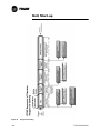
Operation
Maintenance
Series R
Helical Rotary Liquid Chillers
Models RTHD
175-450 ton units (60 Hz)
125-450 ton units (50 Hz)
June 2004
© American Standard Inc. 2004
RTHD-SVX01B-EN
NOTICE: Warnings and Cautions appear at appropriate sections throughout this literature. Read these carefully.
WARNING:
Indicates a potentially hazardous situation which, if not
avoided, could result in death or serious injury.
CAUTION: Indicates a potentially hazardous situation which, if not
avoided, may result in minor or moderate injury. It may also be used to
alert against unsafe practices.
CAUTION: Indicates a situation that may result in equipment or propertydamage only accidents.
Important
Environmental Concerns!
Scientific research has shown that certain man-made chemicals
can affect the earth’s naturally occurring stratospheric ozone layer
when released to the atmosphere. In particular, several of the
identified chemicals that may affect the ozone layer are
refrigerants that contain Chlorine, Fluorine and Carbon (CFCs) and
those containing Hydrogen, Chlorine, Fluorine and Carbon
(HCFCs). Not all refrigerants containing these compounds have
the same potential impact to the environment. Trane advocates
the responsible handling of all refrigerants—including industry
replacements for CFCs such as and HCFCs and HFCs.
Responsible Refrigerant Practices!
Trane believes that responsible refrigerant practices are important
to the environment, our customers, and the air conditioning
industry. All technicians who handle refrigerants must be
certified. The Federal Clean Air Act (Section 608) sets forth the
requirements for handling, reclaiming, recovering and recycling of
certain refrigerants and the equipment that is used in these
service procedures. In addition, some states or municipalities
may have additional requirements that must also be adhered to
for responsible management of refrigerants. Know the applicable
laws and follow them.
WARNING
Contains Refrigerant!
System contains oil and refrigerant under high pressure. Recover
refrigerant to relieve pressure before opening the system. See
unit nameplate for refrigerant type. Do not use non-approved
refrigerants, refrigerant substitutes, or refrigerant additives.
Failure to follow proper procedures or the use of non-approved
refrigerants, refrigerant substitutes, or refrigerant additives could
result in death or serious injury or equipment damage.
2
RTHD-SVX01B-EN
Contents
General Information . . . . . . . . . . . . . . . . . . . . . . . . . . . . . . . . . . . . . . . 9
Literature Change History . . . . . . . . . . . . . . . . . . . . . . . . . . . . . . . . . . . . . . 9
Unit Identification - Nameplates . . . . . . . . . . . . . . . . . . . . . . . . . . . . . . . . . 9
Unit Inspection . . . . . . . . . . . . . . . . . . . . . . . . . . . . . . . . . . . . . . . . . . . . . 10
Inspection Checklist . . . . . . . . . . . . . . . . . . . . . . . . . . . . . . . . . . . . . . . . . 10
Loose Parts Inventory . . . . . . . . . . . . . . . . . . . . . . . . . . . . . . . . . . . . . . . . 10
Unit Description . . . . . . . . . . . . . . . . . . . . . . . . . . . . . . . . . . . . . . . . . . . . . 10
Model Number Coding System . . . . . . . . . . . . . . . . . . . . . . . . . . . . . . . . . 10
Installation Overview . . . . . . . . . . . . . . . . . . . . . . . . . . . . . . . . . . . . . . . . . 19
Installation Mechanical . . . . . . . . . . . . . . . . . . . . . . . . . . . . . . . . . . . . . 25
Storage . . . . . . . . . . . . . . . . . . . . . . . . . . . . . . . . . . . . . . . . . . . . . . . . . . . 25
Location Requirements . . . . . . . . . . . . . . . . . . . . . . . . . . . . . . . . . . . . . . . 25
Moving and Rigging . . . . . . . . . . . . . . . . . . . . . . . . . . . . . . . . . . . . . . . . . . 27
Lifting Procedure . . . . . . . . . . . . . . . . . . . . . . . . . . . . . . . . . . . . . . . . . . . . 31
Isolation Pads . . . . . . . . . . . . . . . . . . . . . . . . . . . . . . . . . . . . . . . . . . . . . . 34
Unit Leveling . . . . . . . . . . . . . . . . . . . . . . . . . . . . . . . . . . . . . . . . . . . . . . . 36
Water Piping . . . . . . . . . . . . . . . . . . . . . . . . . . . . . . . . . . . . . . . . . . . . . . . 37
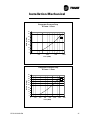
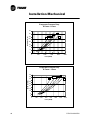
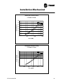
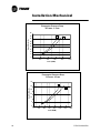
Water Pressure Drop Data . . . . . . . . . . . . . . . . . . . . . . . . . . . . . . . . . . . . 45
Condenser Water Regulating Valve . . . . . . . . . . . . . . . . . . . . . . . . . . . . . . 55
Water Treatment . . . . . . . . . . . . . . . . . . . . . . . . . . . . . . . . . . . . . . . . . . . . 56
Water Pressure Gauges and Thermometers . . . . . . . . . . . . . . . . . . . . . . . 57
Water Pressure Relief Valves . . . . . . . . . . . . . . . . . . . . . . . . . . . . . . . . . . 57
Flow Sensing Devices . . . . . . . . . . . . . . . . . . . . . . . . . . . . . . . . . . . . . . . . 57
Refrigerant Pressure Relief Valve Venting . . . . . . . . . . . . . . . . . . . . . . . . 58
Thermal Insulation . . . . . . . . . . . . . . . . . . . . . . . . . . . . . . . . . . . . . . . . . . . 60
Installation Electrical . . . . . . . . . . . . . . . . . . . . . . . . . . . . . . . . . . . . . . 63
General Recommendations . . . . . . . . . . . . . . . . . . . . . . . . . . . . . . . . . . . . 63
Power Supply Wiring . . . . . . . . . . . . . . . . . . . . . . . . . . . . . . . . . . . . . . . . . 63
Compressor Motor Phase Sequencing . . . . . . . . . . . . . . . . . . . . . . . . . . . 65
Correcting Improper Electrical Phase Sequence . . . . . . . . . . . . . . . . . . . . 66
Application Of Solid-State Starters . . . . . . . . . . . . . . . . . . . . . . . . . . . . . . . . . . 69
Precautions When Using Solid-State Starters . . . . . . . . . . . . . . . . . . . . . . . . . . 72
Module Connections for Interconnecting Wiring . . . . . . . . . . . . . . . . . . . 75
Interconnecting Wiring (Field Wiring Required) . . . . . . . . . . . . . . . . . . . . . 75
Operating Principles Mechanical . . . . . . . . . . . . . . . . . . . . . . . . . . . . . 83
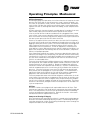
General . . . . . . . . . . . . . . . . . . . . . . . . . . . . . . . . . . . . . . . . . . . . . . . . . . . 83
Refrigeration (Cooling) Cycle . . . . . . . . . . . . . . . . . . . . . . . . . . . . . . . . . . . 83
Compressor Description . . . . . . . . . . . . . . . . . . . . . . . . . . . . . . . . . . . . . . 86
Oil Management System . . . . . . . . . . . . . . . . . . . . . . . . . . . . . . . . . . . . . 88
Oil Cooler . . . . . . . . . . . . . . . . . . . . . . . . . . . . . . . . . . . . . . . . . . . . . . . . . . 90
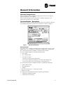
Operator Interface Controls . . . . . . . . . . . . . . . . . . . . . . . . . . . . . . . . . 91
CH530 Communications Overview . . . . . . . . . . . . . . . . . . . . . . . . . . . . . . 91
Controls Interface . . . . . . . . . . . . . . . . . . . . . . . . . . . . . . . . . . . . . . . . . . . 91
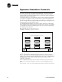
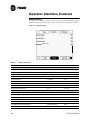
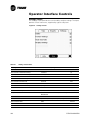
DynaView Interface . . . . . . . . . . . . . . . . . . . . . . . . . . . . . . . . . . . . . . . . . . 92
Display Screens . . . . . . . . . . . . . . . . . . . . . . . . . . . . . . . . . . . . . . . . . . . . . 93
Keypad/Display Lockout Feature . . . . . . . . . . . . . . . . . . . . . . . . . . . . . . . . 94
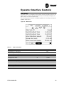
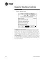
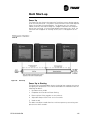
Main Screen . . . . . . . . . . . . . . . . . . . . . . . . . . . . . . . . . . . . . . . . . . . . . . . 95
Reports Screen . . . . . . . . . . . . . . . . . . . . . . . . . . . . . . . . . . . . . . . . . . . . . 100
RTHD-SVX01B-EN
3
Contents
Settings Screen . . . . . . . . . . . . . . . . . . . . . . . . . . . . . . . . . . . . . . . . . . . . . 102
Diagnostic Screen . . . . . . . . . . . . . . . . . . . . . . . . . . . . . . . . . . . . . . . . . . . 104
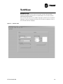
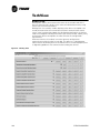
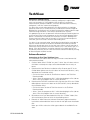
TechView . . . . . . . . . . . . . . . . . . . . . . . . . . . . . . . . . . . . . . . . . . . . . . . 105
Minimum PC requirements to install and operate TechView . . . . . . . . . . 106
Unit View . . . . . . . . . . . . . . . . . . . . . . . . . . . . . . . . . . . . . . . . . . . . . . . . . . 107
Status View . . . . . . . . . . . . . . . . . . . . . . . . . . . . . . . . . . . . . . . . . . . . . . . . 108
Setpoint View . . . . . . . . . . . . . . . . . . . . . . . . . . . . . . . . . . . . . . . . . . . . . . 111
Manual Override View . . . . . . . . . . . . . . . . . . . . . . . . . . . . . . . . . . . . . . . . 115
Diagnostics View . . . . . . . . . . . . . . . . . . . . . . . . . . . . . . . . . . . . . . . . . . . . 117
Software View . . . . . . . . . . . . . . . . . . . . . . . . . . . . . . . . . . . . . . . . . . . . . . 121
Binding View . . . . . . . . . . . . . . . . . . . . . . . . . . . . . . . . . . . . . . . . . . . . . . . 122
Software Download . . . . . . . . . . . . . . . . . . . . . . . . . . . . . . . . . . . . . . . . . . 123
Unit Start-up . . . . . . . . . . . . . . . . . . . . . . . . . . . . . . . . . . . . . . . . . . . . 125
Power Up . . . . . . . . . . . . . . . . . . . . . . . . . . . . . . . . . . . . . . . . . . . . . . . . . 125
Power Up to Starting . . . . . . . . . . . . . . . . . . . . . . . . . . . . . . . . . . . . . . . . . 125
Stopped to Starting: . . . . . . . . . . . . . . . . . . . . . . . . . . . . . . . . . . . . . . . . . 127
Seasonal Unit Start-Up Procedure . . . . . . . . . . . . . . . . . . . . . . . . . . . . . . . 129
Unit Shutdown . . . . . . . . . . . . . . . . . . . . . . . . . . . . . . . . . . . . . . . . . . 133
Normal Shutdown to Stopped . . . . . . . . . . . . . . . . . . . . . . . . . . . . . . . . . . 133
Seasonal Unit Shutdown . . . . . . . . . . . . . . . . . . . . . . . . . . . . . . . . . . . . . . 134
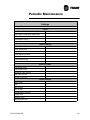
Periodic Maintenance . . . . . . . . . . . . . . . . . . . . . . . . . . . . . . . . . . . . . 135
Overview . . . . . . . . . . . . . . . . . . . . . . . . . . . . . . . . . . . . . . . . . . . . . . . . . . 135
Weekly Maintenance and Checks . . . . . . . . . . . . . . . . . . . . . . . . . . . . . . . 135
Monthly Maintenance and Checks . . . . . . . . . . . . . . . . . . . . . . . . . . . . . . 135
Annual Maintenance . . . . . . . . . . . . . . . . . . . . . . . . . . . . . . . . . . . . . . . . . 136
Scheduling Other Maintenance . . . . . . . . . . . . . . . . . . . . . . . . . . . . . . . . . 137
Maintenance Procedures . . . . . . . . . . . . . . . . . . . . . . . . . . . . . . . . . . 141
Cleaning the Condenser . . . . . . . . . . . . . . . . . . . . . . . . . . . . . . . . . . . . . . 141
Cleaning the Evaporator . . . . . . . . . . . . . . . . . . . . . . . . . . . . . . . . . . . . . . 142
Compressor Oil . . . . . . . . . . . . . . . . . . . . . . . . . . . . . . . . . . . . . . . . . . . . . 142
Oil Sump Level Check . . . . . . . . . . . . . . . . . . . . . . . . . . . . . . . . . . . . . . . . 142
Removing Compressor Oil . . . . . . . . . . . . . . . . . . . . . . . . . . . . . . . . . . . . 144
Oil Charging Procedure . . . . . . . . . . . . . . . . . . . . . . . . . . . . . . . . . . . . . . . 144
Replacing the Main Oil Filter (Hot Filter) . . . . . . . . . . . . . . . . . . . . . . . . . . 145
Replacing the Gas Pump Oil Filter . . . . . . . . . . . . . . . . . . . . . . . . . . . . . . . 146
Refrigerant Charge . . . . . . . . . . . . . . . . . . . . . . . . . . . . . . . . . . . . . . . . . . 146
Refrigerant Charging . . . . . . . . . . . . . . . . . . . . . . . . . . . . . . . . . . . . . . . . . 147
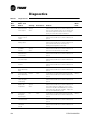
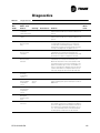
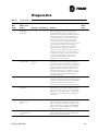
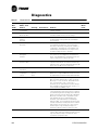
Diagnostics . . . . . . . . . . . . . . . . . . . . . . . . . . . . . . . . . . . . . . . . . . . . . 151
Wiring Schematics . . . . . . . . . . . . . . . . . . . . . . . . . . . . . . . . . . . . . . . 165
Unit Electrical Data . . . . . . . . . . . . . . . . . . . . . . . . . . . . . . . . . . . . . . . . . . 165
4
RTHD-SVX01B-EN
List of Tables
General Information. . . . . . . . . . . . . . . . . . . . . . . . . . . . . . . . . . . . . . . .
Model Number . . . . . . . . . . . . . . . . . . . . . . . . . . . . . . . . . . . . . . . . . . . . .
Compressor Model Number . . . . . . . . . . . . . . . . . . . . . . . . . . . . . . . . . .
Installation Responsibility Chart for RTHD Units . . . . . . . . . . . . . . . . . . .
General Data . . . . . . . . . . . . . . . . . . . . . . . . . . . . . . . . . . . . . . . . . . . . . .
General Data . . . . . . . . . . . . . . . . . . . . . . . . . . . . . . . . . . . . . . . . . . . . . .
General Data . . . . . . . . . . . . . . . . . . . . . . . . . . . . . . . . . . . . . . . . . . . . . .
General Data . . . . . . . . . . . . . . . . . . . . . . . . . . . . . . . . . . . . . . . . . . . . . .
9
11
16
19
21
22
23
24
Installation Mechanical . . . . . . . . . . . . . . . . . . . . . . . . . . . . . . . . . . . . .
Unit Weights (lb (kg)) . . . . . . . . . . . . . . . . . . . . . . . . . . . . . . . . . . . . . . . .
Center of Gravity (in (mm)) . . . . . . . . . . . . . . . . . . . . . . . . . . . . . . . . . . . .
Weights and Rigging . . . . . . . . . . . . . . . . . . . . . . . . . . . . . . . . . . . . . . . .
Evaporator and Condenser Data . . . . . . . . . . . . . . . . . . . . . . . . . . . . . . .
Pressure Relief Valve Data . . . . . . . . . . . . . . . . . . . . . . . . . . . . . . . . . . . .
Recommended Insulation Types . . . . . . . . . . . . . . . . . . . . . . . . . . . . . . .
25
28
30
32
44
59
61
Installation Electrical . . . . . . . . . . . . . . . .
Wire Selection Chart for Starter Panels . . .
Lug Sizes . . . . . . . . . . . . . . . . . . . . . . . . . .
Dip and Rotary Switch Settings . . . . . . . . .
Chiller Events/Status Descriptions . . . . . . .
Programable Relays . . . . . . . . . . . . . . . . . .
63
64
68
70
79
80
......
......
......
......
......
......
.......
.......
.......
.......
.......
.......
......
......
......
......
......
......
....
....
....
....
....
....
Operating Principles Mechanical . . . . . . . . . . . . . . . . . . . . . . . . . . . . . 83
Operator Interface Controls . . . . . . . . . . . . . . . . . . . . . . . . . . . . . . . . . 91
Main Screen Items . . . . . . . . . . . . . . . . . . . . . . . . . . . . . . . . . . . . . . . . . . 95
Operating Modes . . . . . . . . . . . . . . . . . . . . . . . . . . . . . . . . . . . . . . . . . . . 96
Report Screen Items . . . . . . . . . . . . . . . . . . . . . . . . . . . . . . . . . . . . . . . 100
Settings Screen Items . . . . . . . . . . . . . . . . . . . . . . . . . . . . . . . . . . . . . . 102
TechView . . . . . . . . . . . . . . . . . . . . . . . . . . . . . . . . . . . . . . . . . . . . . . . 105
Status View Items . . . . . . . . . . . . . . . . . . . . . . . . . . . . . . . . . . . . . . . . . 109
Configuration View Items. . . . . . . . . . . . . . . . . . . . . . . . . . . . . . . . . . . . 119
Unit Start-up. . . . . . . . . . . . . . . . . . . . . . . . . . . . . . . . . . . . . . . . . . . . . 125
Limit Conditions . . . . . . . . . . . . . . . . . . . . . . . . . . . . . . . . . . . . . . . . . . . 129
Unit Shutdown . . . . . . . . . . . . . . . . . . . . . . . . . . . . . . . . . . . . . . . . . . . 133
Periodic Maintenance . . . . . . . . . . . . . . . . . . . . . . . . . . . . . . . . . . . . . 135
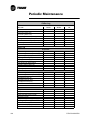
Operating Conditions at Full Load . . . . . . . . . . . . . . . . . . . . . . . . . . . . . 136
Operating Conditions at Minimum Load . . . . . . . . . . . . . . . . . . . . . . . . 136
Maintenance Procedures . . . . . . . . . . . . . . . . . . . . . . . . . . . . . . . . . . . 141
POE Oil Properties . . . . . . . . . . . . . . . . . . . . . . . . . . . . . . . . . . . . . . . . . 142
Low Refrigerant Temperature, Ethylene Glycol, and Freeze Protection Settings . . . . . . . . . . . . . . . . . . . . . . . . . . . . . . . . . . . . . . . . . . . . . . . . . . . . 148
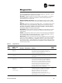
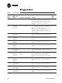
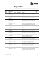
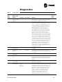
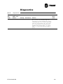
Diagnostics . . . . . . . . . . . . . . . . . . . . . . . . . . . . . . . . . . . . . . . . . . . . . . 151
Diagnostic List . . . . . . . . . . . . . . . . . . . . . . . . . . . . . . . . . . . . . . . . . . . 151
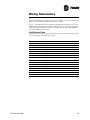
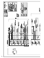
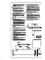
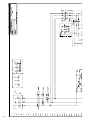
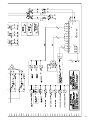
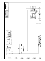
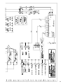
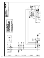
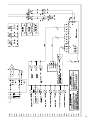
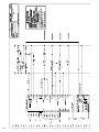
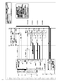
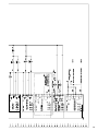
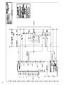
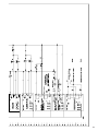
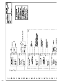
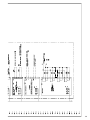
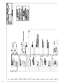
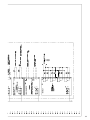
Wiring Schematics . . . . . . . . . . . . . . . . . . . . . . . . . . . . . . . . . . . . . . . . 165
RTHD-SVX01B-EN
5
List of Tables
6
RTHD-SVX01B-EN
List of Figures
General Information. . . . . . . . . . . . . . . . . . . . . . . . . . . . . .
Typical Unit Nameplate . . . . . . . . . . . . . . . . . . . . . . . . . . . .
Component Location for Typical RTHD Unit . . . . . . . . . . . .
Component Location for Typical RTHD Unit (Back View) . .
....
....
....
....
9
9
17
18
Installation Mechanical . . . . . . . . . . . . . . . . . . . . . . . . . . . . . . . . . . . . .
Recommended Operating and Service Clearances . . . . . . . . . . . . . . . . .
Unit Weights and Dimensions for Rigging . . . . . . . . . . . . . . . . . . . . . . . .
Lifting the Unit . . . . . . . . . . . . . . . . . . . . . . . . . . . . . . . . . . . . . . . . . . . . .
Isolator Pad Placement . . . . . . . . . . . . . . . . . . . . . . . . . . . . . . . . . . . . . .
Oil Separator with Shipping Bracket and Compressor Shipping Spacer .
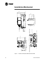
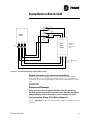
Condenser and Evaporator Water Connections -BBB . . . . . . . . . . . . . . .
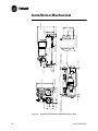
Condenser and Evaporator Water Connections -BCD . . . . . . . . . . . . . . .
Condenser and Evaporator Water Connections - CEF . . . . . . . . . . . . . . .
Condenser and Evaporator Water Connections - CDE/DDE/EDE . . . . . .
Condenser and Evaporator Water Connections - DFF/EFF/CFF . . . . . . . .
Condenser and Evaporator Water Connections - DGG/EGG . . . . . . . . . .
Typical Thermometer, Valving, and Manifold Pressure Gauge Set-up . . .
Relief Valve Location . . . . . . . . . . . . . . . . . . . . . . . . . . . . . . . . . . . . . . . .
Typical RTHD Insulation Requirements . . . . . . . . . . . . . . . . . . . . . . . . . .
25
26
28
33
35
36
38
39
40
41
42
43
57
59
61
Installation Electrical . . . . . . . . . . . . . . . . . . . . . .
Electrical Installation. . . . . . . . . . . . . . . . . . . . . . . .
Control Interface module (CIM) . . . . . . . . . . . . . . .
Solid State Starter Connections . . . . . . . . . . . . . . .
Y-D Starter Panel Power Wire Routing . . . . . . . . .
Solid State Starter Panel Power Wire Routing . . . . . .
....
....
....
....
....
....
63
65
71
72
74
75
Operating Principles Mechanical . . . . . . . . . . . . . . . . . . . . . . . . . . . . .
Pressure /Enthalpy Curve . . . . . . . . . . . . . . . . . . . . . . . . . . . . . . . . . . . . .
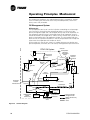
Refrigerant Flow Diagram . . . . . . . . . . . . . . . . . . . . . . . . . . . . . . . . . . . .
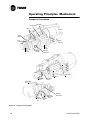
Compressor Description . . . . . . . . . . . . . . . . . . . . . . . . . . . . . . . . . . . . .
Oil Flow Diagram . . . . . . . . . . . . . . . . . . . . . . . . . . . . . . . . . . . . . . . . . . .
Gas Pump. . . . . . . . . . . . . . . . . . . . . . . . . . . . . . . . . . . . . . . . . . . . . . . . .
83
84
85
86
88
90
.......
.......
.......
.......
.......
.......
......
......
......
......
......
......
......
......
......
......
Operator Interface Controls . . . . . . . . . . . . . . . . . . . . . . . . . . . . . . . . . 91
DynaView . . . . . . . . . . . . . . . . . . . . . . . . . . . . . . . . . . . . . . . . . . . . . . . . . 92
TechView . . . . . . . . . . . . . . . . . . . . . . . . . . . . . . . . . . . . . . . . . . . . . . . 105
Unit Start-up. . . . . . . . . . . . . . . . . . . . . . . . . . . . . . . . . . . . . . . . . . . . .
Power Up . . . . . . . . . . . . . . . . . . . . . . . . . . . . . . . . . . . . . . . . . . . . . . . .
Power Up to Starting . . . . . . . . . . . . . . . . . . . . . . . . . . . . . . . . . . . . . . .
Stoped to Starting . . . . . . . . . . . . . . . . . . . . . . . . . . . . . . . . . . . . . . . . .
125
125
126
128
Unit Shutdown . . . . . . . . . . . . . . . . . . . . . . . . . . . . . . . . . . . . . . . . . . . 133
Normal Shutdown . . . . . . . . . . . . . . . . . . . . . . . . . . . . . . . . . . . . . . . . . 133
Periodic Maintenance . . . . . . . . . . . . . . . . . . . . . . . . . . . . . . . . . . . . . 135
Maintenance Procedures . . . . . . . . . . . . . . . . . . . . . . . . . . . . . . . . . . . 141
Determining Oil Level in Sump . . . . . . . . . . . . . . . . . . . . . . . . . . . . . . . 143
Oil Filter Replacement Chart (E,D, C and B Frame Compressors) . . . . . 146
Diagnostics . . . . . . . . . . . . . . . . . . . . . . . . . . . . . . . . . . . . . . . . . . . . . . 151
RTHD-SVX01B-EN
7
List of Figures
Wiring Schematics . . . . . . . . . . . . . . . . . . . . . . . . . . . . . . . . . . . . . . . . 165
8
RTHD-SVX01B-EN
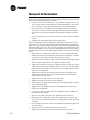
General Information
Literature Change History
RTHD-SVX01B-EN New Evap/Cond configuration C2F2F3 and change to
minimum flow rates. (June 2004)
RTHD-SVX01A-EN New manual describes installation, operation, and
maintenance of RTHD units. (May 2003)
Unit Identification - Nameplates
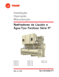
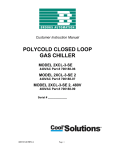
When the unit arrives, compare all nameplate data with ordering, submittal,
and shipping information. A typical unit nameplate is shown in Figure 1.
Figure 1
Typical Unit Nameplate
Unit Nameplates
The RTHD “unit” nameplate is applied to the exterior surface of the starter/
control panel. The “compressor” nameplate is applied to the compressor.
The starter/control panel nameplate is located inside the panel.
The unit nameplate provides the following information:
• Unit model
•
Unit Serial Number
•
Unit device number.
– Identifies unit electrical requirements
– Lists correct operating charges of HFC-134a and refrigerant oil
– Lists unit test pressures and maximum working pressures.
The starter/control panel nameplate provides the following information:
• Panel model number
•
Rated load amps
•
Voltage
• Electrical characteristics - starter type, wiring
• Options included.
The compressor nameplate provides the following information:
• Compressor model descriptor
•
RTHD-SVX01B-EN
Compressor serial number
9
General Information
•
Compressor device number
•
Motor serial number
•
Compressor electrical characteristics
•
Refrigerant.
Unit Inspection
When the unit is delivered, verify that it is the correct unit and that it is properly equipped.
Inspect all exterior components for visible damage. Report any apparent damage or material shortage to the carrier and make a “unit damage” notation on
the carrier’s delivery receipt. Specify the extent and type of damage found
and notify the appropriate Trane Sales Office.
Do not proceed with installation of a damaged unit without sales office
approval.
Inspection Checklist
To protect against loss due to damage incurred in transit, complete the following checklist upon receipt of the unit.
• Inspect the individual pieces of the shipment before accepting the unit.
Check for obvious damage to the unit or packing material.
•
Inspect the unit for concealed damage as soon as possible after delivery
and before it is stored. Concealed damage must be reported within 10
days after receipt.
•
If concealed damage is discovered, stop unpacking the shipment. Do not
remove damaged material from the receiving location. Take photos of the
damage, if possible. The owner must provide reasonable evidence that
the damage did not occur after delivery.
•
Notify the Trane sales representative and arrange for repair. Do not repair
the unit, however, until damage is inspected by the transportation representative.
Loose Parts Inventory
Check all items against the shipping list. Water vessel drain plugs, isolation
pads, rigging and electrical diagrams, service literature and the starter/control
panel wire pullbox (required on some starters) are shipped unassembled in
the starter control panel.
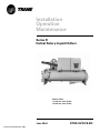
Unit Description
The RTHD units are single compressor, helical-rotary type, water-cooled liquid
chillers designed for installation indoors. Each unit is a completely assembled,
hermetic package that is factory-piped, wired, leak-tested, dehydrated,
charged (optional), and tested for proper control operation before shipment.
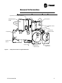
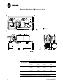
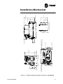
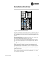
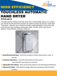
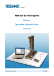
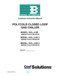
Figure 2 and Figure 3 show a typical RTHD unit and its components. Water
inlet and outlet openings are covered before shipment. The oil tank is factory
charged with the proper amount of refrigeration oil. The unit can be factory
charged with refrigerant.
Model Number Coding System
The model numbers for the unit and the compressor are composed of numbers and letters that represent features of the equipment. Shown in the three
tables following are samples of typical unit, compressor, and panel model
numbers, followed by the coding system for each.
10
RTHD-SVX01B-EN
General Information
Each position, or group of positions, in the model number is used to represent a feature. For example, in the first table, position 08 of the unit model
number, Unit Voltage, contains the letter “F”. An F in this position means that
the unit voltage is 460/60/3.
Unit Model Number
Table 1
Name
Model Number
Code
MODL
M/N Digit
M/N Code
1-4
RTHD
DCTL
Description
Basic product line
RTHD
5
WCBU
Water-Cooled Series R - Dev Sequence D
Manufacturing Plant
U
Water Chiller Business Unit, Pueblo CO USA
EPL
E
Epinal Business Unit, Charmes FR
CHIN
C
China Business Unit
COMP
6-7
Compressor
B1
B1
B1 compressor
B2
B2
B2 compressor
C1
C1
C1 compressor
C2
C2
C2 compressor
D1
D1
D1 compressor
D2
D2
D2 compressor
D3
D3
D3 compressor (50 Hz only)
E3
E3
E3 compressor (50 Hz only)
VOLT
8
Unit power supply
200A
A
200V/60Hz/3Ph power
230A
C
230V/60Hz/3Ph power
380A
D
380V/60Hz/3Ph power
380B
R
380V/50Hz/3Ph power
400B
T
400V/50Hz/3Ph power
415B
U
415V/50Hz/3Ph power
460A
F
460V/60Hz/3Ph power
575A
H
575V/60Hz/3Ph power
SPEC
9
Design Specials
NONE
X
None
ELSE
C
Specials denoted elsewhere
NOT
S
Specials not denoted elsewhere
DSEQ
10-11
A0
AGLT
Design sequence
A0
12
Factory/ABU assigned, start with A0
Agency listing
NONE
X
No agency listing
CUL
U
C/UL listing
CCC
3
CCC- Chinese Compulsory Code
RTHD-SVX01B-EN
11
General Information
Table 1
Name
Model Number
Code
CODE
M/N Digit
13
Description
Pressure vessel code
ASME
A
ASME pressure vessel code
CAN
C
Canadian code
SQLO
L
Chinese code
SPL
EVAP
S
14-15
Special
Evaporator
B1
B1
B1 evaporator
B2
B2
B2 evaporator
C1
C1
C1 evaporator
C2
C2
C2 evaporator
D1
D1
D1 evaporator
D2
D2
D2 evaporator
D3
D3
D3 evaporator
D4
D4
D4 evaporator
D5
D5
D5 evaporator
D6
D6
D5 evaporator
E1
E1
E1 evaporator
F1
F1
F1 evaporator
F2
F2
F2 evaporator
G1
G1
G1 evaporator
G2
G2
G2 evaporator
G3
G3
G3 evaporator
EVTM
16
STD
EVWP
Evap Tube type
A
17
Standard
Evaporator passes
2
2
2 Pass evaporator
3
3
3 Pass evaporator
4
4
4 Pass evaporator
EVWC
18
Evaporator water connection
LH
L
Left hand evaporator connection
RH
R
Right hand evaporator connection
EVCT
19
Evaporator connection type
STD
A
Standard grooved pipe
SPEC
S
Special
EVPR
12
M/N Code
20
Evaporator water side pressure
LOW
L
150 PSI / 10.5 Bar evaporator water pressure
HIGH
H
300 PSI / 21 Bar evaporator water pressure
RTHD-SVX01B-EN
General Information
Table 1
Name
Model Number
Code
COND
M/N Digit
M/N Code
21-22
Description
Condenser
B1
B1
B1 condenser
B2
B2
B2 condenser
D1
D1
D1 condenser
D2
D2
D2 condenser
E1
E1
E1 condenser
E2
E2
E2 condenser
E3
E3
E3 condenser
E4
E4
E4 condenser
E5
E5
E5 condenser
F1
F1
F1 condenser
F2
F2
F2 condenser
F3
F3
F3 condenser
G1
G1
G1 condenser
G2
G2
G2 condenser
G3
CDTM
G3
23
G3 condenser
Condenser tube type
CUFN
A
Enhanced fin - copper
SMBR
B
Smooth bore - copper
SBCN
C
Smooth bore - 90/10 Cu/Ni
CDWP
24
2
CDWC
Condenser passes
2
25
LH
Condenser water connection
L
RH
CDCT
2 Pass
R
26
Left hand condenser connection
Right hand condenser connection
Condenser connection type
STD
A
Standard grooved pipe
MAR
C
Marine
SPEC
S
Special
CDPR
27
Condenser water side pressure
150
L
150 PSI / 10.5 Bar condenser water pressure
300
H
300 PSI / 21 Bar condenser water pressure
CDLW
28
STD
VLVS
Condenser Leaving Water Temp
A
29
Standard (<45 deg C)
Refrigerant specialties
NONE
X
No refrigerant isolation valves
VLV
V
Refrigerant isolation valves
RTHD-SVX01B-EN
13
General Information
Table 1
Name
Model Number
Code
OILC
M/N Digit
30
Oil Cooler
X
without oil cooler
OIL
C
with oil cooler
31
Thermal Insulation
NONE
X
No insulation
INSC
Q
Factory insulation cold parts
SNDA
32
Sound Attenuator
NONE
X
No insulation
INSL
A
Standard attenuator
LANG
33
ENG
SFTY
Control, Label, and Literature Language
E
34
STD
CHRG
English
Safety Devices
X
35
Standard
Shipping Charge
FACT
A
Full Factory Charge
N2
B
Nitrogen
PCKG
36
Shipping Package
DOM
A
Domestic
DMSW
B
Domestic + Shrink Wrap
SKID
C
Skid
SKSW
D
Skid + Shrink Wrap
SPEC
J
Special
FLOW
37
Flow Switch
NONE
X
Without
EVNM
A
Evap NEMA-1
ECNM
B
Evap & Cond NEMA-1
EVVP
C
Evap Vapor
ECVP
D
Evap & Cond Vapor
TEST
38
NONE
Factory Performance Test
X
Without
WIT
C
Witness test
REP
D
Performance test w/report
SPEC
S
Special
SRTY
39
Starter type
YDEL
Y
Wye-delta closed transition starter
SSST
A
Solid State starter
MRLA
40-42
***
***
14
Description
NONE
INSL
MRLA
M/N Code
Design RLA (for starter)
Selection RLA
RTHD-SVX01B-EN
General Information
Table 1
Name
Model Number
Code
PCON
M/N Digit
M/N Code
43
Description
Power line connection type
TERM
A
Terminal block connection for incoming line(s)
DISC
B
Mech disconnect switch
CB
D
Circuit breaker
CBHI
F
High interrupt circuit breaker
GFCB
H
Ground fault circuit breaker
GFHI
J
Ground fault high interrupt circuit breaker
ENC
44
NEMA
WVUO
Enclosure type
A
45
NEMA 1
Under/over voltage protection
NIST
X
No under/over voltage protection
INST
U
Under/over voltage protection
OPIN
46
Unit operator interface
DVA
A
Dyna-View operator interface-Pueblo
DVD
D
Dyna-View/Spanish
DVG
G
Dyna-View/Trad.Chinese
DVH
H
Dyna-View/Simp.Chinese
DVJ
J
Dyna-View/Japanese
DVK
K
Dyna-View/Portugese(Brazil)
DVL
L
Dyna-View/Korean
DVM
M
Dyna-View/Thai
COMM
47
Remote Interfaces (digital comm)
NIST
X
No remote digital comm
TRM4
4
Tracer Comm 4 Interface
TRM5
SETP
5
48
Tracer Comm 5 LCI-C (LonTalk )
External Chilled Water & Current Limit Setpoint
NIST
X
None
INST
4
4-20 ma input
INSA
2
2-10 Vdc input
BSLD
49
External Base Loading
NIST
X
None
INST
4
4-20 ma input
INSA
2
2-10 Vdc input
ICEB
50
Icemaking
NIST
X
None
INST
A
Icemaking with relay
INSA
B
Icemaking without relay
RTHD-SVX01B-EN
15
General Information
Table 1
Name
Model Number
Code
STAT
M/N Digit
M/N Code
51
Description
Programmable Relays
NIST
X
None
INST
R
Programmable Relay
OATS
52
Chilled water reset -outdoor air temp
NIST
X
No Sensor (return water CHW reset standard)
INST
T
Chilled water reset - outdoor air temp
RPOT
53
Reg. Valve & RLA
NIST
X
None
WREG
V
Condenser reg. Valve out & % RLA out
HPC
P
Condenser Pressure (%HPC) & % RLA out
DELP
RMTP
D
Chiller Delta P & %RLA out
54
Refrigerant Monitor Input
NIST
X
None
INST
A
100 ppm / 4-20 ma
INSA
B
1000 ppm / 4-20 ma
INSB
C
100 ppm / 2-10 Vdc
INSC
D
1000 ppm / 2-10 Vdc
Compressor Model Number (located on compressor nameplate):
Table 2
Compressor Model Number
Selection Category
M/N Digit
M/N Code
Description of Selection
Compressor Series
1-4
CHHC
Semi-Hermetic Heli-Rotor Compressor
Design Control
5
1
Pueblo
Compressor Frame
6
B
B Frame
C
C Frame
D
D Frame
E
E Frame
1
Smaller capacity (minor)
2
Larger capacity (major)
3
Special 50 Hz capacity
A
200V/60Hz/3
C
230V/60Hz/3
D
380V/60Hz/3
F
460V/60Hz/3 or 400V/50Hz/3
H
575V/60Hz/3
O
No Specials
Compressor Capacity
Motor
Specials
Design Sequence
16
7
8
9
10-11
C
Specials Denoted Elsewhere
S
Uncategorized Special not denoted elsewhere
AO
1st Design (Factory Input)
RTHD-SVX01B-EN
General Information
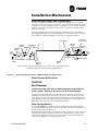
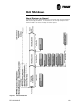
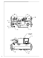
DynaView or EasyView Interface
Oil Separator
Starter/Control
Panel
Relief Valves
Oil Sump
Condenser
Water Outlet
Evaporator
Liquid Level
Sensor
Gas Pump
Figure 2
Evaporator
Water Outlet
Condenser
Water Inlet
Component Location for Typical RTHD Unit
RTHD-SVX01B-EN
17
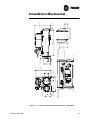
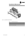
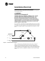
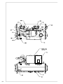
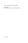
General Information
Oil Separators
Oil Filter (Cold)
Hot Oil Filter is
hidden from view.
Relief Valves
Compressor
Discharge Line
Unit Nameplate
(On side of starter/control panel)
EXVs
Evaporator
Water Inlet
Condenser
Service Valves
(With Refrigerant Isolation
Valve Option Only)
Figure 3
18
Oil Sump
(The oil distribution system is located between
the condenser and the evaporator.)
Component Location for Typical RTHD Unit (Back View)
RTHD-SVX01B-EN
General Information
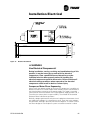
Installation Overview
For convenience, Table 3 summarizes responsibilities that are typically associated with the RTHD chiller installation process.
Table 3
Installation Responsibility Chart for RTHD Units
Requirement
Trane-supplied,
Trane-installed
Trane-supplied,
Field-installed
Rigging
Field-supplied,
Field-installed
Safety chains
Clevis connectors - Lifting beam
Isolation
Electrical
Isolation pads
Isolation pads
Circuit breakers or non-fused
disconnects (optional)
Circuit breaker or non-fused
disconnect handle
Circuit breakers or fusible disconnects (optional)
Unit-mounted starter
Temperature sensor (optional
outdoor air)
Terminal lugs
Flow switches (may be fieldsupplied)
Ground connection(s)
Condenser water regulating valve
controller (optional: may be fieldsupplied)
Jumper bars
BAS wiring (optional)
IPC wiring
Control voltage wiring
High condenser pressure
interlock wiring
Chilled water pump contactor and
wiring
Condenser water pump contactor
and wiring
Optional relays and wiring
Water piping
Flow switches (may be fieldsupplied)
Thermometers
Condenser water regulating valve
controller (optional: may be fieldsupplied)
Water flow pressure gauges
Isolation and balancing valves
water piping
Vents and drain valves
Pressure relief valves (for water
boxes as required)
Pressure Relief
Relief valves
Vent line and flexible connector
Insulation
Insulation (optional)
Insulation
RTHD-SVX01B-EN
19
General Information
Refer to the Installation Mechanical and Installation Electrical sections of this
manual for detailed installation instructions.
• Locate and maintain the loose parts, e.g. isolators, temperature sensors,
flow sensors or other factory-ordered, field-installed options, for installation, as required. Loose parts are located in the starter/control panel.
•
Install the unit on a foundation with flat support surfaces, level within
1/4” (6.35 mm) and of sufficient strength to support concentrated loading. Place the manufacturer-supplied isolation pad assemblies under the
unit.
•
Install the unit per the instructions outlined in the Mechanical Installation
section.
•
Complete all water piping and electrical connections.
NOTE: Field piping must be arranged and supported to avoid stress on the
equipment. It is strongly recommended that the piping contractor provide at
least 3 feet (914 mm) of clearance between the pre-installation piping and the
planned location of the unit. This will allow for proper fit-up upon arrival of the
unit at the installation site. All necessary piping adjustments can be made at
that time. Refer to the current engineering bulletin for further details on installation.
• Where specified, supply and install valves in the water piping upstream
and downstream of the evaporator and condenser water boxes, to isolate
the shells for maintenance and to balance/trim the system.
20
•
Supply and install condenser water control valve(s) per Trane Engineering
Bulletin -Water Cooled Series R Condenser Water Contol.
•
Supply and install flow switches or equivalent devices in both the chilled
water and condenser water piping. Interlock each switch with the proper
pump starter and CH530, to ensure that the unit can only operate when
water flow is established.
•
Supply and install taps for thermometers and pressure gauges in the
water piping, adjacent to the inlet and outlet connections of both the
evaporator and the condenser.
•
Supply and install drain valves on each water box.
•
Supply and install vent cocks on each water box.
•
Where specified, supply and install strainers ahead of all pumps and automatic modulating valves.
•
Supply and install refrigerant pressure relief piping from the pressure
relief to the atmosphere.
•
If necessary, supply enough HCFC-134 refrigerant and dry nitrogen (75
psig) for pressure testing.
•
Start the unit under supervision of a qualified service technician.
•
Where specified, supply and insulate the evaporator and any other portion of the unit, as required, to prevent sweating under normal operating
conditions.
•
For unit-mounted starters, cutouts are provided at the top of the panel for
line-side wiring.
•
Supply and install the wire terminal lugs to the starter.
•
Supply and install field wiring to the line-side lugs of the starter.
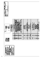
RTHD-SVX01B-EN
General Information
Table 4
General Data
Unit Designator (corresponds to digits 6, 7, 14, 15, 21, 22 of unit model number)
D1D1E1
D1F1F2
D1G2G2
D2D2E2
D2F2F3
D2G3G3
Refrigerant Type
HFC-134a
HFC-134a
HFC-134a
HFC-134a
HFC-134a
HFC-134a
Refrigerant Charge (lb (kg))
475 (216)
625 (284)
700 (318)
475 (216)
625 (284)
700 (318)
Oil Charge (gal (l))
6 (23)
10 (38)
11 (42)
6 (23)
10 (38)
11 (42)
Operating Weight (lb (kg))
15385 (6978)
17537 (7955)
21065 (9555)
15570 (7063)
18220 (8265)
21641 (9816)
Shipping Weight (lb (kg))
14443 (6551)
16187 (7342)
19107 (8667)
14562 (6605)
16820 (7630)
19508 (8849)
General
Overall Dimensions
Length (in (mm))*
126 (3189)
144 (3669)
146 (3712)
126 (3189)
144 (3669)
146 (3712)
Width (in (mm))*
68 (1717)
68 (1716)
70 (1771)
68(1717)
68 (1716)
70 (1771)
Height (in (mm))*
76 (1717)
76 (1716)
80 (2033)
76 (1937)
76 (1936)
80 (2033)
Evaporator
Water Storage (gal (l))
69 (261)
102 (386)
144 (545)
74 (280)
107 (405)
159 (602)
Minimum Flow (gpm (l/s))
Water
415 (26) for
2-pass
563 (36) for
2-pass
550 (35) for
3-pass
450 (28) for
2-pass
604 (38) for
2-pass
622 (39) for
3-pass
275 (17) for
3-pass
376 (24) for
3-pass
411 (26) for
4-pass
300 (20) for
3-pass
404 (25) for
3-pass
466 (29) for
4-pass
498 (31) for
2-pass
676 (43) for
2-pass
660 (42) for
3-pass
541 (34) for
2-pass
725 (46) for
2-pass
747 (47) for
3-pass
330 (21) for
3-pass
454 (29) for
3-pass
492 (31) for
4-pass
357 (23) for
3-pass
487 (31) for
3-pass
557 (35) for
4-pass
1812 (114)
for 2-pass
2478 (156)
for 2-pass
2413 (152)
for 3-pass
1980 (125)
for 2-pass
2667 (168)
for 2-pass
2732 (172)
for 3-pass
1206 (76)
for 3-pass
1655 (104)
for 3-pass
1807 (114)
for 4-pass
1320 (83)
for 3-pass
1780 (112)
for 3-pass
2050 (129)
for 4-pass
Minimum Flow (gpm (l/s))
Brine
Maximum Flow (gpm (l/s))
Condenser
(all are 2-pass)
Water Storage (gal (l))
44 (166)
57 (216)
91 (344)
47 (178)
61 (231)
97 (367)
Minimum Flow (gpm (l/s))
Water
291 (18)
355 (22)
535 (34)
316 (20)
385 (24)
589 (37)
Minimum Flow (gpm (l/s))
Brine
350 (22)
430 (27)
650 (41)
380 (24)
460 (29)
710 (45)
Maximum Flow (gpm (l/s))
1280 (81)
1560 (98)
2360 (149)
1390 (88)
1700 (107)
2600 (164)
All weights ±3%, include standard 150 psig water boxes.
Operating weights include refrigerant, oil, and water charges.
If oil cooler is installed, add 1/4 gal (1 liter) to the oil charge value given for B family units; add 1.0 gal (4 liters) for all other units.
Overall dimensions are based on 3-pass evap/2 pass cond and LH/RH water connections. Refer to submittals for exact job configurations
RTHD-SVX01B-EN
21
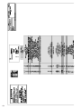
General Information
Table 5
General Data
Unit Designator (corresponds to digits 6, 7, 14, 15, 21, 22 of unit model number)
D3D2E2
D3F2F3
D3G3G3
E3D2E2
E3F2F3
E3G3G3
Refrigerant Type
HFC-134a
HFC-134a
HFC-134a
HFC-134a
HFC-134a
HFC-134a
Refrigerant Charge (lb (kg))
475 (216)
625 (284)
700 (318)
475 (216)
625 (284)
700 (318)
Oil Charge (gal (l))
6 (23)
10 (38)
11 (42)
6 (23)
10 (38)
11 (42)
Operating Weight (lb (kg))
15570 (7063)
18220 (8265)
21641 (9816)
15728 (7134)
18356 (8326)
21786 (9882)
Shipping Weight (lb (kg))
14562 (6605)
16820 (7630)
19508 (8849)
14720 (6677)
16956 (7695)
19653 (8915)
Length (in (mm))
126 (3189)
144 (3669)
146 (3712)
126 (3189)
144 (3669)
146 (3712)
Width (in (mm))
68 (1717)
68 (1716)
70 (1771)
68 (1717)
67 (7716)
70 (1771)
Height (in (mm))
76 (1937)
76 (1936)
80 (2033)
76 (1937)
76 (1936)
80 (2033)
General
Overall Dimensions
Evaporator
Water Storage (gal (l))
74 (280)
107 (405)
159 (602)
74 (280)
107 (405)
159 (602)
Minimum Flow (gpm (l/s))
Water
405 (28) for
2-pass
604 (38) for
2-pass
622 (39) for
3-pass
405 (28) for
2-pass
604 (38) for
2-pass
622 (39) for
3-pass
300 (19) for
3-pass
404 (25) for
3-pass
466 (29) for
4-pass
300 (19) for
3-pass
404 (25) for
3-pass
466 (29) for
4-pass
541 (34) for
2-pass
725 (46) for
2-pass
747 (47) for
3-pass
541 (34) for
2-pass
725 (46) for
2-pass
747 (47) for
3-pass
357 (23) for
3-pass
487 (31) for
3-pass
557 (35) for
4-pass
357 (23) for
3-pass
487 (31) for
3-pass
557 (35) for
4-pass
1980 (125)
for 2-pass
2667 (168)
for 2-pass
2732 (172)
for 3-pass
1980 (125)
for 2-pass
2667 (168)
for 2-pass
2732 (172)
for 3-pass
1320 (83)
for 3-pass
1780 (112)
for 3-pass
2050 (129)
for 4-pass
1320 (83)
for 3-pass
1780 (112)
for 3-pass
2050 (129)
for 4-pass
Minimum Flow (gpm (l/s))
Brine
Maximum Flow (gpm (l/s))
Condenser
(all are 2-pass)
Water Storage (gal (l))
47 (178)
61 (231)
97 (367)
47 (178)
61 (231)
97 (367)
Minimum Flow (gpm (l/s))
Water
316 (20)
355 (22)
589 (37)
316 (20)
355 (22)
589 (37)
Minimum Flow (gpm (l/s))
Brine
380 (24)
460 (29)
710 (45)
380 (24)
460 (29)
710 (45)
Maximum Flow (gpm (l/s))
1390 (88)
1700 (107)
2600 (164)
1390 (88)
1700 (107)
2600 (164)
All weights ±3%, include standard 150 psig water boxes.
Operating weights include refrigerant, oil, and water charges.
If oil cooler is installed, add 1/4 gal (1 liter) to the oil charge value given for B family units; add 1.0 gal (4 liters) for all other units.
Overall dimensions are based on 3-pass evap/2 pass cond and LH/RH water connections. Refer to submittals for exact job configurations
22
RTHD-SVX01B-EN
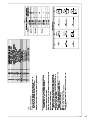
General Information
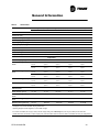
Table 6
General Data
Unit Designator (corresponds to digits 6, 7, 14, 15, 21, 22 of unit model number)
C1D6E5
C1D5E4
C1E1F1
C2D4E4
C2D3E3
General
Refrigerant Type
HFC-134a
HFC-134a
HFC-134a
HFC-134a
HFC-134a
Refrigerant Charge (lb (kg))
490 (222)
490 (222)
525 (238)
490 (222)
490 (222)
Oil Charge (gal (l))
6 (23)
6 (23)
10 (38)
6 (23)
6 (23)
Operating Weight (lb (kg))
13397 (6077)
13673 (6202)
15818 (7175)
13672 (6202)
15044 (6824)
Shipping Weight (lb (kg))
12780 (5797)
12973 (5885)
14718 (6675)
12972 (5884)
14002 (6351)
126 (3194)
126 (3194)
Overall Dimensions
Length (in (mm))*
126 (3194)
Width (in (mm))*
68 (1717)
68 (1717)
68 (1715)
68 (1717)
68 (1717)
Height (in (mm))*
76 (1937)
76 (1937)
76 (1937)
76 (1937)
76 (1937)
126 (3194)
144 (3650)
Evaporator
Water Storage (gal (l))
45 (170)
52 (197)
82 (311)
52 (197)
78 (295)
Minimum Flow (gpm (l/s))
Water
293 (18) for
2-pass
351 (21) for
2-pass
450 (28) for
2-pass
351 (21) for
2-pass
465 (31) for
2-pass
196 (12) for
3-pass
234 (15) or
3-pass
300 (19) for
3-pass
234 (15) or
3-pass
324 (20) for
3-pass
352 (22) for
2-pass
422 (27) for
2-pass
487 (31) for
2-pass
422 (27) for
2-pass
584 (37) for
2-pass
233 (15) for
3-pass
281 (18) or
3-pass
357 (23) for
3-pass
281 (18) or
3-pass
389 (25) for
3-pass
1287 (81) for
2-pass
1542 (97)or
2-pass
1980 (125) for
2-pass
1542 (97)or
2-pass
2131 (134) for
2-pass
860 (54) for
3-pass
1028 (65) or
3-pass
1320 (83) for
3-pass
1028 (65) or
3-pass
1417 (89) for
3-pass
Minimum Flow (gpm (l/s))
Brine
Maximum Flow (gpm (l/s))
Condenser
(all are 2-pass)
Water Storage (gal (l))
29 (110)
32 (121)
60 (226)
32 (121)
47 (178)
Minimum Flow (gpm (l/s))
Water
206 (13)
245 (15)
375 (24)
245 (15)
325 (21)
Minimum Flow (gpm (l/s))
Brine
250 (16)
295 (19)
450 (28)
295 (19)
390 (25)
Maximum Flow (gpm (l/s))
910 (57)
1080 (68)
1650 (104)
1080 (68)
1420 (90)
All weights ±3%, include standard 150 psig water boxes.
Operating weights include refrigerant, oil, and water charges.
If oil cooler is installed, add 1/4 gal (1 liter) to the oil charge value given for B family units; add 1.0 gal (4 liters) for all other units.
Overall dimensions are based on 3-pass evap/2 pass cond and LH/RH water connections. Refer to submittals for exact job configurations
RTHD-SVX01B-EN
23
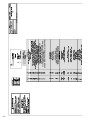
General Information
Table 7
General Data
Unit Designator (corresponds to digits 6, 7, 14, 15, 21, 22 of unit model number)
C2F2F3
B1B1B1
B1C1D1
B2B2B2
B2C2D2
General
Refrigerant Type
HFC-134a
HFC-134a
HFC-134a
HFC-134a
HFC-134a
Refrigerant Charge (lb (kg))
700 (318)
410 (186)
490 ((222)
410 (186)
490 ((222)
Oil Charge (gal (l))
11 (42)
4.5 (17.0)
4.5 (17.0)
4.5 (17.0)
4.5 (17.0)
Operating Weight (lb (kg))
17560 (7965)
9867 (4476)
10554 (4787)
10019 (4544)
10653 (4832)
Shipping Weight (lb (kg))
16168 (7334)
9292 (4215)
9837 (4462)
9402 (4265)
9953 (4515)
Overall Dimensions
Length (in (mm))*
144 (3658)
124 (3160)
143 (3624)
124 (3160)
143 (3624)
Width (in (mm))*
68 (1727)
64 (1634)
64 (1634)
64 (1634)
64 (1634)
Height (in (mm))*
76 (1930)
73 (1849)
73 (1849)
73 (1849)
72 (1849)
Evaporator
Water Storage (gal (l))
107 (405)
41 (155)
55 (208)
45 (170)
58 (220)
Minimum Flow (gpm (l/s))
Water
604 (38) for
2-pass
253 (16) for
2-pass
320 (18) for
2-pass
288 (22) for
2-pass
347 (22) for
2-pass
404 (25) for
3-pass
168 (11) for
3-pass
213 (12) for
3-pass
192 (15) for
3-pass
232 (15) for
3-pass
725 (46) for
2-pass
303 (19) for
2-pass
346 (22) for
2-pass
346 (22) for
2-pass
375 (24) for
2-pass
487 (31) for
3-pass
200 (13) for
3-pass
254 (16) for
3-pass
233 (15) for
3-pass
276 (17) for
3-pass
2667 (168)
for 2-pass
1104 (70) for
2-pass
1412 (89) for
2-pass
1266 (80) for
2-pass
1531 (97) for
2-pass
1780 (112)
for 3-pass
736 (46) for
3-pass
941 (59) for
3-pass
844 (53) for
3-pass
1022 (65) for
3-pass
Minimum Flow (gpm (l/s))
Brine
Maximum Flow (gpm (l/s))
Condenser
(all are 2-pass)
Water Storage (gal (l))
61 (231)
28 (106)
31 (117)
29 (110)
34 (129)
Minimum Flow (gpm (l/s))
Water
355 (22)
193 (12)
193 (12)
212 (13)
212 (13)
Minimum Flow (gpm (l/s))
Brine
460 (29)
230 (15)
230 (15)
255 (16)
255 (16)
Maximum Flow (gpm (l/s))
1700 (107)
850 (54)
850 (54)
935 (59)
935 (59)
All weights ±3%, include standard 150 psig water boxes.
Operating weights include refrigerant, oil, and water charges.
If oil cooler is installed, add 1/4 gal (1 liter) to the oil charge value given for B family units; add 1.0 gal (4 liters) for all other units.
Overall dimensions are based on 3-pass evap/2 pass cond and LH/RH water connections. Refer to submittals for exact job configurations
24
RTHD-SVX01B-EN
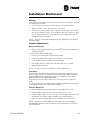
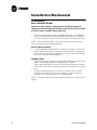
Installation Mechanical
Storage
If the chiller is to be stored more than one month prior to installation, observe
the following precautions:
• Do not remove the protective coverings from the electrical panel.
•
Store the chiller in a dry, vibration-free, secure area.
•
At least every three months, attach a gauge and manually check the pressure in the refrigerant circuit. If the refrigerant pressure is below 71 psig
at 70oF (or 46 psig at 50oF), call a qualified service organization and the
appropriate Trane sales office.
NOTE: Pressure will be approximately 20 psig if shipped with the optional
nitrogen charge.
Location Requirements
Noise Considerations
•
Refer to Trane Engineering Bulletin -Series R Chiller Sound Ratings and
Installation Guide.
for sound consideration applications.
• Locate the unit away from sound-sensitive areas.
•
Install the isolation pads under the unit. Refer to “Unit Isolation.”
•
Install rubber vibration isolators in all water piping.
•
Use flexible electrical conduit for final connection to the CH530.
•
Seal all wall penetrations.
NOTE: Consult an acoustical engineer for critical applications.
Foundation
Provide rigid, non-warping mounting pads or a concrete foundation of sufficient strength and mass to support the chiller operating weight (including
completed piping and full operating charges of refrigerant, oil and water).
Refer to Table 8 for unit operating weights.
Once in place, level the chiller within 1/4” (6.35 mm) over its length and
width.
The Trane Company is not responsible for equipment problems resulting from
an improperly designed or constructed foundation.
Vibration Eliminators
• Provide rubber boot type isolators for all water piping at the unit.
•
Provide flexible conduit for electrical connections to the unit.
•
Isolate all pipe hangers and be sure they are not supported by main structure beams that could introduce vibration into occupied spaces.
•
Make sure that the piping does not put additional stress on the unit.
NOTE: Do not use metal braided type eliminators on the water piping.
Metal braided eliminators are not effective at the frequencies at which the
unit will operate.
RTHD-SVX01B-EN
25
Installation Mechanical
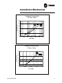
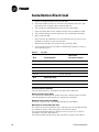
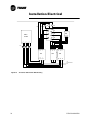
Clearances
Provide enough space around the unit to allow the installation and maintenance personnel unrestricted access to all service points. Refer to submittal
drawings for the unit dimensions.
Allow adequate clearance for condenser and compressor servicing. A minimum of three feet is recommended for compressor service and to provide
sufficient clearance for the opening of control panel doors. Refer to Figure 4
for minimum clearances required for condenser tube service. In all cases,
local codes will take precedence over these recommendations.
NOTE: Required vertical clearance above the unit is 36” (914.4 mm). There
should be no piping or conduit located over the compressor motor.
If the room configuration requires a variance to the clearance dimensions,
contact your Trane sales office representative.
3'-0" (914 mm)
Servic e Cl earance
3'-0" (914 mm)
Servic e Cl earance
(Opposi te Tube Removal)
36. 5" (927 mm)
Radius
105 ~ Swing
26.4" (671 mm)
Radius
3'-0" (91 4 mm)
Se rvice Clearance
3 '-0" (9 14 mm)
Se rvice Cleara nce
Tube Removal
Cleara nce
(Eithe r End)
E DE, DDE, CDE, BBB:
1 08" (27 43 mm)
E FF, DFF, CEF, BCD:
1 26" (32 00 mm)
E GG, DGG, CGG:
1 30" (33 02 mm)
Figure 4
26
Recommended Operating and Service Clearances
RTHD-SVX01B-EN
Installation Mechanical
NOTE: Maximum clearances are given. Depending on the unit configuration, some units may require less clearance than others in the same
category.
Ventilation
The unit produces heat even though the compressor is cooled by the refrigerant. Make provisions to remove heat generated by unit operation from the
equipment room. Ventilation must be adequate to maintain an ambient temperature lower than 122oF (50oC).
Vent the evaporator, condenser and compressor pressure relief valves in
accordance with all local and national codes. Refer to Table 12.
Make provisions in the equipment room to keep the chiller from being
exposed to freezing temperatures (32 oF/0oC).
Water Drainage
Locate the unit near a large capacity drain for water vessel drain-down during
shutdown or repair. Condensers and evaporators are provided with drain connections. Refer to “Water Piping.” All local and national codes apply.
Access Restrictions
Door clearances for the RTHD units are given in Figure 5. Refer to the unit
submittals for specific “per unit” dimensional information.
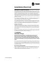
Moving and Rigging
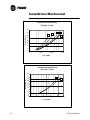
The Model RTHD chiller should be moved by lifting at designated lift points
only. Refer to Figure 6 and Table 8 for typical unit lifting and operating
weights. Refer to the rigging diagram that ships with each unit for specific
“per unit” weight data.
WARNING
Heavy Equipment!
Always use lifting equipment with a capacity exceeding unit
lifting weight by an adequate safety factor. (+10%). Follow the
procedures and diagrams in this manual and in the submittal.
Failure to do so can result in death or serious injury.
RTHD-SVX01B-EN
27
Installation Mechanical
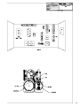
B
C
= C.G.
X
A
D
Z
Y
Figure 5
Unit Weights and Dimensions for Rigging
Table 8
Unit Weights (lb (kg))
Location (points)
Unit Designator *
A
B
C
D
E3G3G3
5339
(2422)
4455
(2021)
4374
(1984)
5486
(2488)
E3F2F3
4781
(2169)
3582
(1625)
3750
(1701)
4851
(2200)
E3D2E2
3796
(1722)
2834
(1285)
3300
(1497)
4789
(2172)
D3G3G3
5320
(2413)
4451
(2019)
4327
(1963)
5140
(2331)
*Unit Designator (corresponds to digits 6, 7, 14, 15, 21, 22 of unit model number)
28
RTHD-SVX01B-EN
Installation Mechanical
Table 8
Unit Weights (lb (kg))
Location (points)
Unit Designator *
A
B
C
D
D3F2F3
4737
(2149)
3563
(1616)
4797
(2176)
4797
(2176)
D3D2E2
3754
(1703)
2818
(1278)
3269
(1483)
4720
(2141)
D2G3G3
5320
(2413)
4451
(2019)
4327
(1963)
5140
(2331)
D2F2F3
4737
(2149)
3563
(1616)
4797
(2176)
4797
(2176)
D2D2E2
3754
(1703)
2818
(1278)
3269
(1483)
4720
(2141)
D1G2G2
5216
(2366)
4344
(1970)
4231
(1919)
5316
(2411)
D1F1F2
4526
(2053)
3452
(1566)
3615
(1640)
4594
(2084)
D1D1E1
3728
(1691)
2758
(1251)
3236
(1468)
4694
(2129)
C2F2F3
4649
2109
3496
1586
4707
2135
4707
2135
C2D3E3
3612
(1638)
2738
(1242)
3148
(1428)
4503
(2043)
C2D4E4
3374
(1530)
2479
(1124)
2876
(1305)
4243
(1925)
C1E1F1
4205
(1907)
3046
(1382)
3196
(1450)
4271
(1937)
C1D5E4
2275
(1032)
2479
(1124)
2876
(1305)
4243
(1925)
C1D6E5
3330
(1510)
2430
(1102)
2825
(1281)
4195
(1903)
B2C2D2
3162
(1510)
2297
(1042)
1767
(802)
2726
(1237)
B2B2B2
2522
(1144)
1996
(905)
1926
(874)
2958
(1342)
B1C1D1
3136
(1422)
2264
(1027)
1739
(789)
2698
(1224)
B1B1B1
2495
(1132)
1969
(893)
1901
(862)
2928
(1328)
*Unit Designator (corresponds to digits 6, 7, 14, 15, 21, 22 of unit model number)
RTHD-SVX01B-EN
29
Installation Mechanical
Table 9
Center of Gravity (in (mm))
Unit Configuration*
E3G3G3
X
Y
30.8
63.81
(782.32)
(1621)
E3F2F3
27.64
63.46
(702.056
(1612)
E3D2E2
25.9
60.05
(658)
(1525)
D3G3G3
30.85
63.48
(784)
(1612)
D3F2F3
27.7
63.4
(704)
(1610)
D3D2E2
25.97
59.95
(660)
(1523)
D2G3G3
30.85
63.48
(784)
(1612)
D2F2F3
27.7
63.4
(704)
(1610)
D2D2E2
25.97
59.95
(660)
(1523)
D1G2G2
30.77
63.55
(782)
(1614)
D1F1F2
27.92
63.47
(709)
(1612)
D1D1E1
25.91
60
(658)
(1524)
C2F2F3
27.92
63.47
(709)
(1612)
C2D3E3
26.13
59.74
(664)
(1517)
C2D4E4
26.13
59.74
(664)
(1517)
C1E1F1
26.36
63.49
(670)
(1613)
C1D5E4
26.13
59.74
(664)
(1517)
C1D6E5
26.13
59.74
(664)
(1517)
B2C2D2
22.4
58.29
(569)
(1481)
B2B2B2
22.88
58.11
(581)
(1476)
B1C1D1
22.32
58.23
(567)
(1479)
B1B1B1
22.84
58.13
(580)
(1477)
Designator corresponds to digits 6, 7, 14, 15, 21, 22 of model number
30
Z
37.62
(956)
38.33
(974)
40.5
(1029)
37.44
(951)
38.14
(969)
40.31
(1024)
37.44
(951)
38.14
(969)
40.31
(1024)
37.72
(958)
38.7
(9833)
40.47
(1028)
38.7
(9833)
40.08
(1018)
40.08
(1018)
40.95
(1040)
40.08
(1018)
40.08
(1018)
33.51
(851)
35.43
(900)
33.65
(855)
35.59
(904)
RTHD-SVX01B-EN
Installation Mechanical
Lifting Procedure
CAUTION
Equipment Damage!
Never use a forklift to move the unit. The skid is not designed to
support the unit at any one point and using a forklift to move the
equipment may cause unit damage. Always position the lifting
beam so that cables do not contact the unit. Failure to do so may
result in unit damage.
NOTE: If absolutely necessary, the chiller can be pushed or pulled across a
smooth surface if it is bolted to wood shipping mounts.
WARNING
Shipping Mounts!
Do not use the threaded holes in the compressor to lift or assist in
lifting the unit. They are not intended for that purpose and could
create a dangerous situation. Do not remove the wood mounts
until the unit is in its final location. Removal of wood shipping
mounts prior to unit final locating could result in death or serious
injury or equipment damage.
1.
When the unit is at its final location, remove the shipping bolts that
secure the unit to the wood base mounts.
2. Rig the unit properly and lift from above or jack the unit (alternate moving
method). Use the points shown on the rigging diagram that ships with
the unit as shown in Figure 6. Remove the base mounts.
3. Install clevis connectors in lifting holes provided on the unit. Attach lifting
chains or cables to clevis connectors as shown in Figure 6. Each cable
alone must be strong enough to lift the chiller.
RTHD-SVX01B-EN
31
Installation Mechanical
Table 10
Rigging
Unit
Configuration*
E3G3G3
Dimension (mm (in))
A
B
C
D
E
F
3658
3353
1621
20
661
610
(144.02)
(132.01)
(63.82)
(0.79)
(26.02)
(24.02)
E3F2F3
3658
3353
1612
29
615
610
(144.02)
(132.01)
(63.46)
(1.14)
(24.21)
(24.02)
E3D2E2
3048
2743
1525
116
612
610
(120.00)
(107.99)
(60.04)
(4.57)
(24.09)
(24.02)
3658
3353
1612
99
654
610
(144.02)
(132.01)
(63.46)
(3.90)
(25.75)
(24.02)
3658
3353
1610
101
617
610
(144.02)
(132.01)
(63.39)
(3.98)
(24.29)
(24.02)
3048
2743
1523
188
614
610
(120.00)
(107.99)
(59.96)
(7.40)
(24.17)
(24.02)
D2G3G3
3658
3353
1612
99
654
610
(144.02)
(132.01)
(63.46)
(3.90)
(25.75)
(24.02)
D2F2F3
3658
3353
1610
101
617
610
(144.02)
(132.01)
(63.39)
(3.98)
(24.29)
(24.02)
3048
2743
1523
188
614
610
(120.00)
(107.99)
(59.96)
(7.40)
(24.17)
(24.02)
D3G3G3
D3F2F3
D3D2E2
D2D2E2
D1G2G2
3658
3353
1614
97
661
610
(144.02)
(132.01)
(63.54)
(3.82)
(26.02)
(24.02)
D1F1F2
3658
3353
1612
99
622
610
(144.02)
(132.01)
(63.46)
(3.90)
(24.49)
(24.02)
D1D1E1
3048
2743
1524
187
612
610
(120.00)
(107.99)
60.00)
(7.36)
(24.09)
(24.02)
3658
3353
1610
101
617
610
(144.02)
(132.01)
63.39)
(3.98)
(24.29)
(24.02)
3048
2743
1517
225
618
610
(120.00)
(107.99)
(59.72)
(8.86)
(24.33)
(24.02)
C2D4E4
3048
2743
1523
219
584
610
(120.00)
(107.99)
(59.96)
(8.62)
(22.99)
(24.02)
C1E1F1
3658
3353
1613
129
624
610
(144.02)
(132.01)
(63.50)
(5.08)
(24.57)
(24.02)
3048
2743
1523
219
584
610
(120.00)
(107.99)
(59.96)
(8.62)
(22.99)
(24.02)
3048
2743
1524
218
582
610
(120.00)
(107.99)
(60.00)
(8.58)
(22.91)
(24.02)
3658
3353
1481
93
523
610
(144.02)
(132.01)
(58.31)
(3.66)
(20.59)
(24.02)
C2F2F3
C2D3E3
C1D5E4
C1D6E5
B2C2D2
*Designator corresponds to digits 6, 7, 14, 15, 21, 22 of model number
32
RTHD-SVX01B-EN
Installation Mechanical
Table 10
Rigging
Unit
Configuration*
Dimension (mm (in))
A
B
C
D
E
B2B2B2
3048
2743
1476
98
535
610
(120.00)
(107.99)
(58.11)
(3.86)
(21.06)
(24.02)
3658
3353
1479
95
521
610
(144.02)
(132.01)
(58.23)
(3.74)
(20.51)
(24.02)
3048
2743
1447
97
534
610
(120.00)
(107.99)
(56.97)
(3.82)
(21.02)
(24.02)
B1C1D1
B1B1B1
F
*Designator corresponds to digits 6, 7, 14, 15, 21, 22 of model number
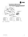
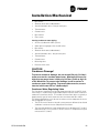
NOTES:
1. LIFTING CABLES (C HAIN S) WIL L N OT BE TH E SAME L EN GTH.
ADJUST TO KEEP UNIT L EVEL WHILE L IFTING.
2. ATTACH ANTI-ROLLING C ABL E (CH AIN) AS SHOWN WITHOUT TENSION.
NOT AS A LIFTING CABLE, BUT TO PREVENT U NIT FROM ROL LIN G.
3. DO NOT FORK LIFT UNIT.
4. WEIGHTS ARE TYPICAL FOR U NITS WITH R-13 4a CHARGE.
A
5. IF U NIT IS DISASSEMBLED, SEE SERVICE BU LLETIN
FOR LIFTING AND RIGGIN G OF C OMPONENTS.
WARN IN G: D O NOT USE C ABL ES (CHAINS) OR SLINGS EXCEPT AS SHOWN.
OTHER LIFTING ARRANGEMENTS MAY C AU SE EQU IPMENT D AMAGE OR
E
SERIOUS PERSONAL INJURY.
B
D
C
ANTI-R OLL IN G
CABLE
ANTI-ROL LING CABLE
ANTI-ROLLING CABL E
EYELET OR M16 INTERN AL THREAD
F (MIN)
L IFTING HOLES
STARTER
C ONTROLS
n 44 ,5 MM TYP
CON D
CON D
EVAP
EVAP
UN IT MODEL NUMBER LOCATION
Figure 6
Lifting the Unit
4. Attach cables to lifting beam. Total lifting weight, lifting weight distribution
and required lifting beam dimensions are shown in the rigging diagram
shipped with each unit and in Figure 6. The lifting beam crossbar must be
positioned so the lifting cables do not contact unit piping or electrical
panel enclosure.
RTHD-SVX01B-EN
33
Installation Mechanical
WARNING
Anti- rotation Strap!
Connect an anti-rotation strap between the lifting beam and
compressor before lifting unit. Failure to do so may result in death
or serious injury should a lifting cable fail.
5. Connect an anti-rotation strap or cable loosely between the lifting beam
and the threaded coupling or eyelet provided at the top of the compressor. Use an eyebolt or clevis to secure the strap at the coupling or eyelet.
NOTE: The anti-rotation strap is not a lifting chain, but a safety device to
ensure that the unit cannot tilt during lifting.
Alternate Moving Method
6. If it is not possible to rig from above as shown in the figures, the unit may
also be moved by jacking each end high enough to move an equipment
dolly under each tube sheet support. Once securely mounted on the dollies, the unit may be rolled into position.
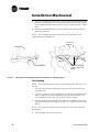
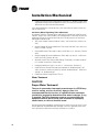
Isolation Pads
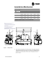
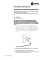
7.
The elastomeric pads shipped (as standard) are adequate for most installations. For additional details on isolation practices, refer to
Trane Engineering Bulletin -Series R Chiller Sound Ratings and Installation Guide., or consult an acoustical engineer for sound-sensitive installations.
During final positioning of the unit, place the isolation pads under the
evaporator and condenser tube sheet supports as shown in Figure 7.
Level the unit as described in the next main paragraph.
NOTE: Durometer values for isolator pads are a measure of resilience. See
Figure 7.
34
RTHD-SVX01B-EN
Installation Mechanical
Note: Level unit to 1/4” (6.35 mm) across
width and length
Typical Elastomeric
Isolation Pad
B
A (hidden leg)
D
C
Durometer: 50 +/-5
Durometer: 40 +/-5
0.31
Figure 7
Pads extend the full
width of legs
Durometer: 55 +/-10
0.31
0.31
Isolator Pad Placement
RTHD-SVX01B-EN
35
Installation Mechanical
8. The unit is shipped with four spacers (only three on B family) on the compressor mount that protect the compressor isolation pads during shipping
and in handling. Remove these spacers (Figure 8) before the unit is operated.
9. Remove the shipping brackets from the bottom sides of the oil separator(s) (see Figure 8).
NOTE: Once shipping bracket(s) is removed, the oil separator is only
supported by the discharge line.
Compressor
Housing
Oil Separator
M20 bolt
Shipping Bracket
Remove 4 Shipping
Spacers (only 3 on B
family)
Figure 8
Oil Separator with Shipping Bracket and Compressor Shipping Spacer
Unit Leveling
NOTE: The electrical panel side of the unit is designated as the “front” of
the unit.
1.
Check unit level end-to-end by placing a level on the top surface of the
evaporator shell.
2. If there is insufficient surface available on the top of the evaporator shell,
attach a magnetic level to the bottom of the shell to level the unit. The
unit should be level to within 1/4” (6.35 mm) over its length.
3. Place the level on the evaporator shell tube sheet support to check sideto-side (front-to-back) level. Adjust to within 1/4” (6.35 mm) of level frontto-back.
NOTE: The evaporator MUST be level for optimum heat transfer and unit
performance.
4. Use full-length shims to level the unit.
36
RTHD-SVX01B-EN
Installation Mechanical
Water Piping
Piping Connections
CAUTION
Equipment Damage!
To prevent equipment damage, bypass the unit if using an acidic
flushing agent.
Make water piping connections to the evaporator and condenser. Isolate and
support piping to prevent stress on the unit. Construct piping according to
local and national codes. Insulate and flush piping before connecting to unit.
Use grooved pipe connectors for all water piping connections. Evaporator and
condenser water inlet and outlet sizes and locations are shown by the unit
submittals and in Figure 9 through Figure 14. The designation in the tables
corresponds to the compressor frame code followed by the evaporator shell
code followed by the condenser shell code as given in the unit model number, digits 6, 7, 14, 15, 21 and 22. Table 11 gives additional water connection
information.
Reversing Water Boxes
All water boxes may be reversed end-for-end. Do not rotate water boxes.
Remove the sensors from the wells before removing the water box. Complete the water box switch and replace the sensors. See Figure 9 through Figure 14 for correct orientation of the water inlet and outlet.
If the water boxes are reversed, be sure to properly rewire the water temperature sensors in the control panel.
NOTE: Be certain to replace water boxes right-side-up to maintain proper
baffle orientation. Use new o-rings.
RTHD-SVX01B-EN
37
Figure 9
38
0.08 [2 mm]
8.00 [203 mm] for 150 psi
8.50 [216 mm] for 300 psi
13.50 [343 mm]
11.50 [292 mm]
23.50 [597 mm]
IN
64.34 [1634 mm]
COND
IN
OUT
9.50 [241 mm]
OIL SUMP
CONDENSER
13.35 [339 mm]
97.51 [2477 mm]
EVAP
70.30 [1786 mm]
10.23 [260 mm]
EVAPOR ATOR
4.97 [126 mm] for 150 ps i
5.47 [139 mm] for 300 ps i
13.84 [351 mm]
8.38 [213 mm]
IN
2 Pass Evap Connection Configuration
(left or right hand) Depending on Water Inlet
6.87 [174 mm]
107.66 [2734 mm]
Standard 3 Pass
EVAPORATOR
15.09 [383 mm]
8.94 [227 mm]
8.38 [213 mm]
27.34 [694mm]
OUT
28.59 [726 mm]
72.80 [1849 mm]
Installation Mechanical
Condenser and Evaporator Water Connections -BBB
RTHD-SVX01B-EN
Figure 10
RTHD-SVX01B-EN
8.00 [203 mm] for 150 psi
8.50 [216 mm] for 300 psi
11.50 [292 mm]
13.50 [343 mm]
23.50 [597 mm]
7.91 [201 mm]
64.34 [1634 mm]
COND
IN
OUT
IN
EVAP
OIL SUMP
118.00 [2997 mm]
CONDENSER
13.35 [339 mm]
9.50 [241 mm]
70.80 [1798 mm]
IN
0.01 [0 mm]
EVAPORATOR
4.97 [126 mm] for 150 psi
5.47 [139 mm] for 300 psi
13.84 [351 mm]
8.38 [213 mm]
2 Pass Evap Connection Configuration
(left or right hand) Depending on Water Inlet
7.87 [174 mm]
125.91 [3198 mm]
Standard 3 Pass
EVAPORATOR
15.09 [383 mm]
8.94 [227 mm]
8.38 [213 mm]
27.34 [694 mm]
OUT
28.59 [726 mm]
72.80 [1849 mm]
Installation Mechanical
Condenser and Evaporator Water Connections -BCD
39
Figure 11
40
IN
IN
67.54 [1715 mm]
COND
OUT
4.84 [123 mm]
8.00 [203 mm] for 150 psi
8.50 [216 mm] for 300 psi
12.49 [317 mm]
14.13 [359 mm]
25.88 [657 mm]
EVAP
CONDENSER
OIL SUMP
118.00 [2997 mm]
14.50 [368 mm]
5.29 [134 mm]
73.44 [1865 mm]
14.88 [378 mm]
9.06 [230 mm]
EVAPORATOR
6.00 [153 mm] for 150 psi
6.50 [165 mm] for 300 psi
3.07 [78 mm]
IN
2 Pass Evap Connection Configuration
(left or right hand) Depending on Water Inlet
7.67 [195 mm]
125.91 [3198 mm]
Standard 3 Pass
EVAPORATOR
OUT
9.42 [239 mm]
15.38 [391 mm]
29.63 [753 mm]
9.06 [230 mm]
30.13 [765 mm]
76.24 [1937 mm]
Installation Mechanical
Condenser and Evaporator Water Connections - CEF
RTHD-SVX01B-EN
Figure 12
RTHD-SVX01B-EN
2.56 [65 mm]
8.00 [203 mm] for 150 psi
8.50 [216 mm] for 300 psi
97.50 [2477 mm]
OIL SUMP
CONDENSER
67.58 [1717 mm]
12.49 [317 mm]
EVAP
5.29 [134 mm]
IN
14.50 [368 mm]
COND
IN
OUT
14.13 [359 mm]
25.88 [657 mm]
73.44 [1865 mm]
7.59 [193 mm]
EVAPORATOR
6.00 [153 mm] for 150 psi
6.50 [166 mm] for 300 psi
14.88 [378 mm]
8.84 [225 mm]
IN
2 Pass Evap Connection Configuration
(left or right hand) Depending on Water Inlet
7.67 [195 mm]
107.66 [2734 mm]
Standard 3 Pass
EVAPORATOR
29.63 [753 mm]
9.06 [230 mm]
9.50 [241 mm]
15.38 [391 mm]
OUT
30.13 [765 mm]
76.27 [1937 mm]
Installation Mechanical
Condenser and Evaporator Water Connections - CDE/DDE/EDE
41
Figure 13
42
4.87 [124 mm]
8.00 [203 mm] for 150 psi
8.50 [216 mm] for 300 psi
CONDENSER
118.00 [2997 mm]
16.20 [411 mm]
67.54 [1716 mm]
EVAP
12.49 [317 mm]
COND
IN
OIL SUMP
73.52 [1867 mm]
3.59 [91 mm]
IN
OUT
14.13 [359 mm]
25.88 [657 mm]
EVAPORATOR
6.15 [156 mm] for 150 psi
6.65 [169 mm] for 300 psi
IN
3.04 [77 mm]
11.43 [290 mm]
9.16 [233 mm]
2 Pass Evap Connection Configuration
(left or right hand) Depending on Water Inlet
8.71 [221 mm]
125.91 [3198 mm]
Standard 3 Pass
EVAPORATOR
10.88 [276 mm]
12.55 [319 mm]
27.30 [693 mm]
28.43 [722 mm]
OUT
9.38 [238 mm]
76.23 [1936 mm]
Installation Mechanical
Condenser and Evaporator Water Connections - DFF/EFF/CFF
RTHD-SVX01B-EN
Figure 14
RTHD-SVX01B-EN
3.22 [82 mm]
9.88 [251 mm] for 300 psi
9.13 [232 mm] for 150 psi
14.70 [373 mm]
14.73 [374 mm]
29.02 [737 mm]
IN
69.72 [1771 mm]
COND
OUT
IN
OUT
CONDENSER
OIL SUMP
18.63 [473 mm]
1.18 [30 mm]
129.80 [3297 mm]
EVAP
22.50 [571 mm]
77.29 [1963 mm]
EVAPORATOR
7.62 [194 mm] for 300 ps i
7.25 [184 mm] for 150 ps i
IN
OUT
0.67 [17 mm]
11.39 [289 mm]
33.89 [861 mm]
10.88 [276 mm]
32.64 [829 mm]
12.29 [312 mm]
2 Pass Evap Connection Configuration
(left or right hand) Depending on Water Inlet
125.91 [3198 mm]
Standard 4 Pass
EVAPORATOR
12.38 [314 mm]
12.64 [321 mm]
9.35 [238 mm]
80.02 [2033 mm]
Installation Mechanical
Condenser and Evaporator Water Connections - DGG/EGG
43
Installation Mechanical
Table 11
Evaporator and Condenser Data
Nom.
Conn.
Size
(NPS)*
Compress
or Frame
Code
(Digit 6,7
of Model
No.)
Evap Shell
Code (Digits
14, 15 of
Model No.)
Evap.
Shell
Diameter
(in)
Nominal Connector
size (NPS)*
2Pass
3Pass
4Pass
Cond Shell
Code
(Digits 21,22 of
Model No.)
E3
D2
26.5
8
8
-
E2
22.0
8
F2
29.0
8
8
-
E2
22.0
8
G3
33.5
-
10
8
G3
25.75
8
D2
26.5
8
8
-
E2
22.0
8
F2
29.0
10
8
-
F3
22.0
8
G3
33.5
-
10
8
G3
25.75
8
D2
26.5
8
8
-
E2
22.0
8
F2
29.0
10
8
-
F3
22.0
8
G3
33.5
-
10
8
G3
25.75
8
D1
26.5
8
8
-
E1
22.0
8
F1
29.0
10
8
-
F2
22.0
8
G2
33.5
-
10
8
G2
25.75
8
D3
26.5
8
8
-
E3
22.0
8
D4
26.5
8
8
E4
22.0
8
F2
29.0
10
8
-
F3
22.0
8
D6
26.5
8
8
-
E5
22.0
8
D3
D2
D1
C2
C1
B2
B1
Cond.
Shell
Diameter
(in)
2-Pass
D5
26.5
8
8
-
E4
22.0
8
E1
33.5
8
8
-
F1
22.0
8
C2
23.0
-
6
-
D2
18.75
6
B2
23.0
-
6
-
B2
18.75
6
C1
23.0
-
6
-
D1
18.75
6
B1
23.0
-
6
-
B1
18.75
6
Metric Conversion is:
6 NPS = 150 mm nominal
8 NPS = 200 mm nominal
10 NPS = 250 mm nominal
44
RTHD-SVX01B-EN
Installation Mechanical
Water Pressure Drop Data
Evaporator Pressure Drop
G Frame - 3 Pass
50
G2
45
G1
G3
Delt-P (Ft H 2O)
40
35
30
25
20
15
10
5
0
0
500
1000
1500
2000
2500
3000
Flow (GPM)
Evaporator Pressure Drop
G Frame - 4 Pass
70
G2
Delt-P (Ft H 2O)
60
G1
G3
50
40
30
20
10
0
0
500
1000
1500
2000
Flow (GPM)
RTHD-SVX01B-EN
45
Installation Mechanical
Evaporator Pressure Drop
F Frame - 2 Pass
35
F1
Delt-P (Ft H 2O)
30
F2
25
20
15
10
5
0
0
500
1000
1500
2000
2500
3000
Flow (GPM)
Evaporator Pressure Drop
F Frame - 3 Pass
50
45
F1
F2
Delt-P (Ft H 2O)
40
35
30
25
20
15
10
5
0
0
500
1000
1500
2000
Flow (GPM)
46
RTHD-SVX01B-EN
Installation Mechanical
Evaporator Pressure Drop
E Frame - 2 Pass
40
35
Delt-P (Ft H 2O)
30
E1
25
20
15
10
5
0
0
500
1000
1500
2000
Flow (GPM)
Evaporator Pressure Drop
E Frame - 3 Pass
50
45
E1
Delt-P (Ft H 2O)
40
35
30
25
20
15
10
5
0
0
200
400
600
800
1000
1200
1400
Flow (GPM)
RTHD-SVX01B-EN
47
Installation Mechanical
Evaporator Pressure Drop
D Frame - 2 Pass
40
Delt-P (Ft H 2O)
35
D2
D1
30
D4 & D5
D3
D6
25
20
15
10
5
0
0
500
1000
1500
2000
2500
Flow (GPM)
Evaporator Pressure Drop
D Frame - 3 Pass
45
40
D4 & D5
D2
D6
35
Delt-P (Ft H 2O)
D1
D3
30
25
20
15
10
5
0
0
200
400
600
800
1000
1200
1400
Flow (GPM)
48
RTHD-SVX01B-EN
Installation Mechanical
Evaporator Pressure Drop
C Frame - 2 Pass
35
C1
30
Delt-P (Ft H 2O)
C2
25
20
15
10
5
0
0
500
1000
1500
Flow (GPM)
Evaporator Pressure Drop
C Frame - 3 Pass
50
C1
45
C2
Delt-P (Ft H 2O)
40
35
30
25
20
15
10
5
0
0
200
400
600
800
1000
Flow (GPM)
RTHD-SVX01B-EN
49
Installation Mechanical
Evaporator Pressure Drop
B Frame - 3 Pass
45
40
B1
B2
Delt-P (Ft H 2O)
35
30
25
20
15
10
5
0
0
200
400
600
800
1000
Flow (GPM)
Evaporator Pressure Drop
B Frame - 2 Pass
30
B1
25
Delt-P (Ft H 2O)
B2
20
15
10
5
0
0
200
400
600
800
1000
1200
1400
Flow (GPM)
50
RTHD-SVX01B-EN
Installation Mechanical
Condenser Pressure Drop
G Frame - 2 Pass
60
Delt-P (Ft H 2O)
50
G2
G1
G3
40
30
20
10
0
0
500
1000
1500
2000
2500
3000
Flow (GPM)
Condenser Pressure Drop
F Frame - 2 Pass
45
F2
40
F1 & F3
Delt-P (Ft H 2O)
35
30
25
20
15
10
5
0
0
500
1000
1500
2000
Flow (GPM)
RTHD-SVX01B-EN
51
Installation Mechanical
Condenser Pressure Drop
E Frame - 2 Pass
40
E1
Delt-P (Ft H 2O)
35
E5
30
E2
E4
E3
25
20
15
10
5
0
0
500
1000
1500
Flow (GPM)
Condenser Pressure Drop
D Frame - 2 Pass
45
40
D1
Delt-P (Ft H 2O)
35
D2
30
25
20
15
10
5
0
0
200
400
600
800
1000
Flow (GPM)
52
RTHD-SVX01B-EN
Installation Mechanical
Condenser Pressure Drop
B Frame - 2 Pass
40
Delt-P (Ft H 2O)
35
B1
30
B2
25
20
15
10
5
0
0
200
400
600
800
1000
Flow (GPM)
Making Grooved Pipe Connections
CAUTION
Equipment Damage!
To prevent damage to water piping, do not overtighten
connections. To prevent equipment damage, bypass the unit if
using an acidic flushing agent.
NOTE: Make sure that all piping is flushed and cleaned prior to starting the
unit.
Vents and Drains
Install pipe plugs in evaporator and condenser water box drain and vent connections before filling the water systems.
To drain water, remove vent and drain plugs, install a NPT connector in the
drain connection with a shutoff valve and connect a hose to it.
Evaporator Piping Components
NOTE: Make sure all piping components are between the shutoff valves, so
that isolation can be accomplished on both the condenser and the evaporator.
RTHD-SVX01B-EN
53
Installation Mechanical
“Piping components” include all devices and controls used to provide proper
water system operation and unit operating safety. These components and
their general locations are given below.
Entering Chilled Water Piping
• Air vents (to bleed air from system)
•
Water pressure gauges with shutoff valves
•
Pipe unions
•
Vibration eliminators (rubber boots)
•
Shutoff (isolation) valves
•
Thermometers
•
Cleanout tees
•
Pipe strainer
•
Flow switch
Leaving Chilled Water Piping
• Air vents (to bleed air from system)
•
Water pressure gauges with shutoff valves
•
Pipe unions
•
Vibration eliminators (rubber boots)
•
Shutoff (isolation) valves
•
Thermometers
•
Cleanout tees
•
Balancing valve
•
Pressure relief valve
CAUTION
Evaporator Damage!
To prevent evaporator damage, do not exceed 150 psig (10.3 bar)
evaporator water pressure for standard water boxes. Maximum
pressure for high pressure water boxes is 300 psig (20.7 bar).
Refer to digit 14 of the Model No. To prevent tube damage, install
a strainer in the evaporator water inlet piping. To prevent tube
corrosion, ensure that the initial water fill has a balanced pH.
Condenser Piping Components
“Piping components” include all devices and controls used to provide proper
water system operation and unit operating safety. These components and
their general locations are given below.
Entering condenser water piping.
• Air vents (to bleed air from system)
•
54
Water pressure gauges with shutoff valves
RTHD-SVX01B-EN
Installation Mechanical
•
Pipe unions
•
Vibration eliminators (rubber boots)
•
Shutoff (isolation) valves. One per each pass
•
Thermometers
•
Cleanout tees
•
Pipe strainer
•
Flow switch
Leaving condenser water piping.
• Air vents (to bleed air from system)
•
Water pressure gauges with shutoff valves
•
Pipe unions
•
Vibration eliminators (rubber boots)
•
Shutoff (isolation) valve - one per each pass
•
Thermometers
•
Cleanout tees
•
Balancing valve
•
Pressure relief valve.
CAUTION
Condenser Damage!
To prevent condenser damage, do not exceed 150 psig (10.3 bar)
water pressure for standard water boxes. Maximum pressure for
high pressure water boxes is 300 psig (20.7 bar). Refer to digit 18
of the Model No. To prevent tube damage, install a strainer in
condenser water inlet piping. To prevent tube corrosion, ensure
that the initial water fill has a balanced pH.
Condenser Water Regulating Valve
The Condenser Head Pressure Control Option provides for a 0-10VDC (maximum range - a smaller range is adjustable) output interface to the customer's
condenser water flow device. The condenser water flow device is typically a
large butterfly type (6" or 8") automatic valve for 200 to 400 Ton chillers.
The following guidelines must be met in order to ensure adequate oil circulation throughout the system.
• The RTHD must maintain a 23 psid system pressure differential at all load
conditions in order to ensure adequate oil circulation.
•
RTHD-SVX01B-EN
The entering condenser water temperature must be above 55°F (12.8°C)
or between 45°F (7.2°C) and 55°F (12.8°C) with a 1°F temperature rise per
minute to 55°F (12.8°C).
55
Installation Mechanical
•
Condenser leaving water temperature must be 17°F degrees higher than
evaporator leaving water temperature within 2 minutes of startup. A 25°F
diferential must be maintained thereafter.
If the above guidelines cannot be met, then some form of tower water control must be used.
Condenser Water Regulating Valve Adjustment
A separate TechView Settings Menu tab entitled "Condenser Head Pressure
Control - Setup" that is only visible if the configuration is selected, contain the
following settings and manual overrides for user adjustments and commissioning all under one tab:
• "Off State" Output Command (0-10 Vdc 0.1 volt increments, Default 2.0
Vdc)
•
Output Voltage @ Desired Minimum Flow (Adj: 0 to 10.0 in 0.1 volt increments, Default 2.0 Vdc)
•
Desired Minimum Flow (Adj: 0- 100% of full flow in 1% intervals, Default
20%)
•
Output Voltage @ Desired Maximum Flow (Adj: 0 to 10.0 in .1 volt increments (or finer), Default 10 Vdc)
•
Actuator Stroke Time (Min to Max Range Time) (Adj: 1 to 1000 seconds,
in 1 second increments, Default 30s)
•
Damping Coefficient (adj: 0.1 to 1.8 , in .1 increments, Default .5)
•
Head Pressure Control Override (enumeration of: disabled (auto), "off"
state, minimum, maximum (100%),) default :disabled (auto). When this
setting is in "disabled (auto)"
•
Condenser Water Pump Prerun Time ( )
Water Treatment
CAUTION
Proper Water Treatment!
The use of untreated or improperly treated water in a RTHD may
result in scaling, erosion, corrosion, algae or slime. It is
recommended that the services of a qualified water treatment
specialist be engaged to determine what water treatment, if any,
is required. The Trane Company assumes no responsibility for
equipment failures which result from untreated or improperly
treated water, or saline or brackish water.
Using untreated or improperly treated water in these units may result in inefficient operation and possible tube damage. Consult a qualified water treatment specialist to determine whether treatment is needed.
56
RTHD-SVX01B-EN
Installation Mechanical
Water Pressure Gauges and Thermometers
Install field-supplied thermometers and pressure gauges (with manifolds,
whenever practical) as shown in Figure 15. Locate pressure gauges or taps in
a straight run of pipe; avoid placement near elbows, etc. Be sure to install the
gauges at the same elevation on each shell if the shells have opposite-end
water connections.
To read manifolded water pressure gauges, open one valve and close the
other (depending upon the reading desired). This eliminates errors resulting
from differently calibrated gauges installed at unmatched elevations.
Flow Switch
Cond Water
Reg. Valve (Opt.)
Shutoff
Valves
Manifold
Flow Switch
Shutoff
Valves
Manifold
Isolation
Valves
Isolation
Valves
Cond
Water
Flow
Evap
Water
Flow
Pressure Differential
Gauge
Thermometers
Pressure Differential
Gauge
Thermometers
Relief
Valve
Relief
Valve
Refer to Trane Engineering Bulletin -Series RChiller Sound Ratings and
Installation Guide for sound-sensitive applications.
Figure 15
Typical Thermometer, Valving, and Manifold Pressure Gauge Set-up
Water Pressure Relief Valves
CAUTION
Shell Damage!
Install a pressure relief valve in both evaporator and condenser
water systems. Failure to do so may result in shell damage.
Install a water pressure relief valve in one of the condenser and one of the
evaporator water box drain connections or on the shell side of any shutoff
valve. Water vessels with close-coupled shutoff valves have a high potential
for hydrostatic pressure buildup on a water temperature increase. Refer to
applicable codes for relief valve installation guidelines.
Flow Sensing Devices
The installer must provide flow switches or differential pressure switches
with pump interlocks to sense system water flow. Flow switch locations are
schematically shown in Figure 15.
To provide chiller protection, install and wire flow switches in series with the
water pump interlocks, for both chilled water and condenser water circuits
(refer to the Installation Electrical section). Specific connections and schematic wiring diagrams are shipped with the unit.
RTHD-SVX01B-EN
57
Installation Mechanical
Flow switches must stop or prevent compressor operation if either system
water flow drops off below the required minimum shown on the pressure
drop curves. Follow the manufacturer’s recommendations for selection and
installation procedures. General guidelines for flow switch installation are outlined below.
• Mount the switch upright, with a minimum of 5 pipe diameters straight,
horizontal run on each side.
•
Do not install close to elbows, orifices or valves.
NOTE: The arrow on the switch must point in the direction of the water
flow.
•
To prevent switch fluttering, remove all air from the water system
NOTE: The CH530 provides a 6-second time delay on the flow switch input
before shutting down the unit on a loss-of-flow diagnostic. Contact a qualified
service organization if nuisance machine shutdowns persist.
•
Adjust the switch to open when water flow falls below nominal. Refer to
the General Data table in Section 1 for minimum flow recommendations
for specific water pass arrangements. Flow switch contacts are closed on
proof of water flow.
Refrigerant Pressure Relief Valve Venting
WARNING
Hazardous Gases!
Consult local regulations for any special relief line requirements.
Refrigerant vented into a confined equipment room could
displace available oxygen to breathe, causing possible
asphyxiation or other serious health risks. Failure to follow these
recommendations could result in death or serious injury.
NOTE: Vent pipe size must conform to the ANSI/ASHRAE Standard 15 for
vent pipe sizing. All federal, state, and local codes take precedence over any
suggestions stated in this manual.
All relief valve venting is the responsibility of the installing contractor.
All RTHD units use evaporator, compressor, and condenser pressure relief
valves (Figure 16) that must be vented to the outside of the building.
Relief valve connection sizes and locations are shown in the unit submittals.
Refer to local codes for relief valve vent line sizing information.
Caution
Equipment Damage!
Do not exceed vent piping code specifications. Failure to comply
with specifications may result in capacity reduction, unit damage
and/or relief valve damage.
58
RTHD-SVX01B-EN
Installation Mechanical
Relief valve discharge setpoints and capacities rates are given in Table 12.
Once the relief valve has opened, it will reclose when pressure is reduced to
a safe level.
NOTE: Once opened, relief valves may have tendency to leak and must be
replaced.
Discharge Pipes
*
*
Evaporator Shell
Condenser Shell
* Valve is hidden by pipe
Figure 16
Relief Valve Location
Pressure relief valve discharge capacities will vary with shell diameter and
length and also compressor displacement. Discharge venting capacity should
be calculated as required by ASHRAE Standard 15-94. Do not adjust relief
valve setting in the field.
Table 12
Pressure Relief Valve Data
Valve Location
Discharge
Setpoint
(psi)
Number
of Valves
Rated Capacity
per Relief Valve
(lba/min.)
Field Connection
Pipe Size (in NPT)
Factory
Shell Side
Connection(in)
Evap - B1
200
1
48.0
1
1-5/16 -12
Evap - B2
200
1
48.0
1
1-5/16 -12
Evap -B3
200
1
48.0
1
1-5/16 -12
Evap -C1
200
1
48.0
1
1-5/16 -12
Evap - C2
200
1
48.0
1
1-5/16 -12
Evap - D1
200
1
48.0
1
1-5/16 -12
Evap - D2
200
1
48.0
1
1-5/16 -12
Evap - D3
200
1
48.0
1
1-5/16 -12
Evap - D4
200
1
48.0
1
1-5/16 -12
Evap - D5
200
1
48.0
1
1-5/16 -12
Evap - D6
200
1
48.0
1
1-5/16 -12
Evap - E1
200
1
48.0
1
1-5/16 -12
Evap - F1
200
1
48.0
1
1-5/16 -12
Evap - F2
200
1
48.0
1
1-5/16 -12
Evap - G1
200
1
78.8
1-1/4
1-5/8 - 12
Evap - G2
200
1
78.8
1-1/4
1-5/8 - 12
RTHD-SVX01B-EN
59
Installation Mechanical
Table 12
Pressure Relief Valve Data
Valve Location
Evap - G3
Cond - B1
Discharge
Setpoint
(psi)
200
200
Number
of Valves
1
2
Rated Capacity
per Relief Valve
(lba/min.)
78.8
48.0
Field Connection
Pipe Size (in NPT)
1-1/4
1
Factory
Shell Side
Connection(in)
1-5/8 - 12
1-5/16 -12
Cond - B2
200
2
48.0
1
1-5/16 -12
Cond - D1
200
2
48.0
1
1-5/16 -12
Cond - D2
200
2
48.0
1
1-5/16 -12
Cond - E1
200
2
48.0
1
1-5/16 -12
Cond - E2
200
2
48.0
1
1-5/16 -12
Cond - E3
200
2
48.0
1
1-5/16 -12
Cond - E4
200
2
48.0
1
1-5/16 -12
Cond - E5
200
2
48.0
1
1-5/16 -12
Cond - F1
200
2
48.0
1
1-5/16 -12
Cond - F2
200
2
48.0
1
1-5/16 -12
Cond - F3
200
2
48.0
1
1-5/16 -12
Cond - G1
200
2
48.0
1
1-5/16 -12
Cond - G2
200
2
48.0
1
1-5/16 -12
Cond - G3
200
2
48.0
1
1-5/16 -12
Comp - B1/B2*
200
2
78.8
1-1/4
1-5/8 - 12
Comp - C1/C2*
200
3
78.8
1-1/4
1-5/8 - 12
Comp - D1/D2/D3*
200
3
78.8
1-1/4
1-5/8 - 12
Comp -E3*
200
3
78.8
1-1/4
1-5/8 - 12
* Only used with isolation valve option
Thermal Insulation
All RTHD units are available with optional factory installed thermal insulation.
If the unit is not factory insulated, install insulation over the areas shaded in
Figure 17. Refer to Table 13 for types and quantities of insulation required.
NOTE: Liquid line filter, refrigerant charging valves, water temperature
sensors, drain and vent connections when insulated must remain accessible
for service.
NOTE: Use only water-base latex paint on factory-applied insulation. Failure
to do so may result in insulation shrinkage.
NOTE: Units in environments with higher humidity or very low leaving water
temperature may require thicker insulation
60
RTHD-SVX01B-EN
Installation Mechanical
.
Figure 17
Typical RTHD Insulation Requirements
Table 13
RTHD-SVX01B-EN
Recommended Insulation Types
Location
Type
Sq. Feet
Evaporator
3/4” wall
90
Compressor
3/4” wall
25
All components and piping on low side of system (gas
pump, return oil line, filter from pump)
3/4” wall
160
61
Installation Mechanical
62
RTHD-SVX01B-EN
Installation Electrical
General Recommendations
For proper electrical component operation, do not locate the unit in areas
exposed to dust, dirt, corrosive fumes, or excessive humidity. If any of these
conditions exist, corrective action must be taken.
WARNING
Hazardous Voltage!
Disconnect all electric power, including remote disconnects
before servicing. Follow proper lockout/tagout procedures to
ensure the power can not be inadvertently energized. Failure to
disconnect power before servicing could result in death or serious
injury.
All wiring must comply with local and National Electric Codes. Minimum circuit ampacities and other unit electrical data is on the unit nameplate. See the
unit order specifications for actual electrical data. Specific electrical schematics and connection diagrams are shipped with the unit.
Typical wiring diagrams are in the back of this manual.
CAUTION
Use Copper Conductors Only!
Unit terminals are not designed to accept other types of
conductors. Failure to use copper conductors may result in
equipment damage.
Do not allow conduit to interfere with other components, structural members
or equipment. All conduit must be long enough to allow compressor and
starter removal.
NOTE: To prevent control malfunctions, do not run low voltage wiring (<30V)
in conduit with conductors carrying more than 30 volts.
Power Supply Wiring
Model RTHD chillers are designed according to NEC Article 310-15; therefore,
all power supply wiring must be sized and selected accordingly by the project
engineer.
For a complete discussion on the use of conductors, see Trane Engineering
Bulletin EB-MSCR-40.
Refer to Trane Engineering Bulletin CTV-EB-93 for power wire sizing.
Water Pump Power Supply
Provide power supply wiring with fused disconnect for both the chilled water
and condenser water pumps.
RTHD-SVX01B-EN
63
Installation Electrical
Electrical Panel Power Supply
Power supply wiring instructions for the starter/control panel are:
1. Run line voltage wiring in conduit to access opening(s) on starter/control
panel or pull-box. See CTV-EB-93 for wire sizing and selection information
and refer to Table 14 that show typical electrical connection sizes and
locations. Always refer to submittal information for your actual unit specifications.
Table 14
Wire Selection Chart for Starter Panels
Min.
Wire
Size
Copper
750C
Supply Leads for All Starters (0 - 2000 Volts)
1 Conduit
3 Wire
1 Conduit
6 Wire
1 Conduit
9 Wire
2
Conduits
6 Wire
2
Conduits
12 Wire
3
Conduits
9 Wire
4
Conduits
12 Wire
8
40
*
*
*
*
*
*
6
52
*
*
*
*
*
*
4
68
*
*
*
*
*
*
3
60
*
*
*
*
*
*
2
92
*
*
*
*
*
*
1
104
*
*
*
*
*
*
0
120
192
252
360
384
360
480
00
140
224
294
420
448
420
560
000
160
256
336
480
512
480
640
0000
184
294
386
552
589
552
736
250
204
326
428
612
653
612
816
300
228
356
479
684
730
684
912
350
248
397
521
744
794
744
992
400
268
429
563
804
858
804
1072
500
304
486
638
912
973
912
1216
Conductors to the starter and motor connected in parallel (electrically joined at both ends to form a single conductor)
must be sized 0 (1/0) or larger per NEC 310-4. Each phase must be equally represented in each conduit.
64
RTHD-SVX01B-EN
Installation Electrical
Figure 18
Electrical Installation
WARNING
Live Electrical Components!
During installation, testing, servicing and troubleshooting of this
product, it may be necessary to work with live electrical
components. Have a qualified licensed electrician or other
individual who has been properly trained in handling live
electrical components perform these tasks. Failure to follow all
electrical safety precautions when exposed to live electrical
components could result in death or serious injury.
Compressor Motor Phase Sequencing
Always verify that proper rotation of the Series R compressor is established
before the machine is started. Proper motor rotation requires confirmation of
the electrical phase sequence of the power supply. The motor is internally
connected for clockwise rotation with incoming power supply phased A, B, C.
To confirm the correct phase sequence (ABC), use a Model 45 Associated
Research Phase indicator or equivalent.
Basically, voltages generated in each phase of a polyphase alternator or circuit
are called phase voltages. In a three-phase circuit, three sine wave voltages
are generated, differing in phase by 120 electrical degrees. The order in which
the three voltages of a three-phase system succeed one another is called
RTHD-SVX01B-EN
65
Installation Electrical
phase sequence or phase rotation. This is determined by the direction of rotation of the alternator. When rotation is clockwise, phase sequence is usually
called “ABC,” when counterclockwise, “CBA.”
This direction may be reversed outside the alternator by interchanging any
two of the line wires. It is this possible interchange of wiring that makes a
phase sequence indicator necessary if the operator is to quickly determine
the phase rotation of the motor.
Correcting Improper Electrical Phase Sequence
Proper compressor motor electrical phasing can be quickly determined and
corrected before starting the unit. If using an Associated Research Model 45
Phase Sequence Indicator, follow this procedure:
1. Press the STOP button to insure the unit will not attempt to start the
compressor.
2. Open the electrical disconnect or circuit protection switch that provides
line power to the line power terminal block in the control panel (or to the
unit-mounted disconnect).
3. Connect the phase sequence indicator leads to the line power terminal
block (or the unit mounted disconnect) as follows:
Phase Seq. Lead
Black (Phase A)
1TB1 Terminal
L1
Red (Phase B)
L2
Yellow (Phase C)
L3
4. Turn power on by closing the unit supply power disconnect switch.
5. Read the phase sequence on the indicator. The “ABC” indicator on the
face of the phase indicator will glow if phase is “ABC”.
WARNING
Hazardous Voltage!
Disconnect all electric power, including remote disconnects
before servicing. Follow proper lockout/tagout procedures to
ensure the power can not be inadvertently energized. Failure to
disconnect power before servicing could result in death or serious
injury.
6. If the “CBA” indicator glows instead, open the unit main power disconnect and switch two line leads on the line power terminal block (or the
unit mounted disconnect). Reclose the main power disconnect and
recheck phasing.
7.
Reopen the unit disconnect and disconnect the phase indicator.
Terminal Lugs
Proper starter/control panel line-side lug sizes are specified on the starter
submittals. These lug sizes must be compatible with conductor sizes specified by the electrical engineer or contractor. Appropriate lug sizes are provided.
66
RTHD-SVX01B-EN
Installation Electrical
Circuit Breakers and Non-Fused Disconnect Switches (factory installed
Option)
Units that are ordered with factory installed Circuit Breakers or Non-Fused
Disconnect Switches ship with the handle in the control panel. The handle
must be installed prior to starting the unit.
The operating mechanism is already pre installed on the Disconnect/ Circuit
Breaker frame.
The hole locations and shafts lengths have already been cut. And the shaft
already installed.
WARNING
Hazardous Voltage!
Disconnect all electric power, including remote disconnects
before servicing. Follow proper lockout/tagout procedures to
ensure the power can not be inadvertently energized. Failure to
disconnect power before servicing could result in death or serious
injury.
1.
Carefully remove the inner portion of the gasket/template keeping the
outer ring and place it between the handle assembly and the door.
Loosely drive the four ¼-20 x 0.5 screws through the door and gasket
mounting holes from the inside of the enclosure door cover and into the
handle assembly. Tighten evenly. ( for International applications the hardware is similar to the M6x1x12mm screw if original hardware is misplaced)
Figure 19. Handle on Door
2. With power isolated from the circuit breaker, test function of installed
handle mechanism in the following manner.
RTHD-SVX01B-EN
a
Close enclosure door. Switch handle mechanism to ON.
b
Check the handle mechanism switches the circuit breaker to the ON position and the enclosure door can not be opened.
67
Installation Electrical
c
Switch the handle mechanism to OFF position.
d
Check that handle mechanism switches circuit breaker to the OFF position and that the enclosure door cannot be opened.
e
Turn Handle to the OPEN position and insure the door opens.
f
Close enclosure door. Switch handle mechanism/circuit breaker to ON.
g
Turn interlock defeater counter clockwise with a flat-blade screwdriver.
h
Open enclosure door.
i
Press the Push to Trip button in the circuit breaker trip unit with a small
flat-blade screwdriver to trip circuit breaker.
j
Align handle assembly with shaft and close enclosure door.
k
Switch handle mechanism to OPEN COVER (RESET) position. Check to
insure breaker resets.
Table 15
Lug Sizes
RLA
Circuit Breaker
Non-fused
Disconnect Switch
1-185
(2) 2/0 - 250 MCM or (1)2/0 - 500
(1) #4 - 350 MCM
186-296
(2) 2/0 - 250 MCM or 2/0 - 500
297-444
(2) 3/0 - 350 MCM
445-592
(2) 1 - 500 MCM
593-888
(4) 4/0 - 500 MCM
RLA
Main Lugs Only
1-623
(2) #4-500 MCM
624-888
(4) #4/0-500 MCM
Fused Disconnect Switches
Size fused disconnects in accordance with NEC Article 440-22(a).
Rated Load Amperage (RLA)
The compressor motor RLA for a particular chiller is determined by the field
selection program and indicated on the compressor nameplate.
Minimum Circuit Ampacity (MCA)
The MCA is equal to 1.25 x the compressor RLA (on nameplate).
Maximum Fuse/Circuit Breaker Size
The maximum fuse/circuit breaker size is equal to 2.25 x the compressor RLA
in accordance with UL 1995, para. 36.15.See also NEC 440-22.
The recommended dual element (RDE) fuse size is equal to 1.75 x RLA in
accordance with NEC Table 430-152.
For recommended field connection lug sizes (RTHD starters) see Table 15.
68
RTHD-SVX01B-EN
Installation Electrical
Application Of Solid-State Starters
The Intelligent Technologies (IT) Inside the Delta Soft Starter is an electronic,
self-contained, panel- or enclosure-mounted motor soft-starting device. It is
intended to provide 3-phase delta-connected induction motors with a smooth
start both mechanically and electrically. The IT line of soft starters utilizes six
SCRs in 3 anti-parallel; one pair in series with each phase winding of the
Delta-connected motor. Controlling the SCRs' conduction period controls the
voltage applied to the motor. This in turn controls the torque developed by the
motor. After the motor reaches speed, contacts inside the starter are closed
to bypass the SCRs.
The Intelligent Technologies (IT) Soft Starter is designed to fulfill the industrial
service requirements for applications such as Chillers and Compressors
where Wye-Delta starters are historically applied.
The Intelligent Technologies (IT) Soft Starter meets all relevant specifications
set forth by NEMA ICS 1, ICS 2 and ICS 5, UL 508, IEC 60947-4-2, CE, and
CSA. This user manual covers useful information that is necessary to know in
order to set-up, operate, troubleshoot and maintain the IT Soft Starter.
Settings and Interface
To program and operate the IT starter, a “Control Interface Module” (CIM) is
used. The CIM is mounted on the front face of the IT starter. The CIM contains the dip switches and rotary controls used to select the settings of the IT
starter. Also on the CIM are LEDs that provide status concerning unit operation and faults.
Note that any change to a dip switch will cause all LEDs to flash momentarily.
Any adjustment to a rotary control will cause the LEDs to light, and they will
stay lit until the adjustment has been completed.
WARNING
Hazardous Voltage!
Disconnect all electric power, including remote disconnects
before servicing. Follow proper lockout/tagout procedures to
ensure the power can not be inadvertently energized. Failure to
disconnect power before servicing could result in death or serious
injury.
The IT Starter does not have to be powered in order to make adjustments on
the CIM. Once the unit is energized, the CIM will load its parameters into the
IT starter. To verify the CIM is operational press the “fault reset” button that
is just below the CIM. All LEDs will momentarily flash if the CIM is powered
and communicating.
Dip and Rotary Switch Settings
Refer to the following table for the recommended settings on the CIM. If a
switch is labeled “non-settable”, this means that feature is internally set at a
fixed value for the Trane application, and it can not be changed using the
switches. Moving the switch will have no effect.
RTHD-SVX01B-EN
69
Installation Electrical
Table 16
Dip and Rotary Switch Settings
CIM Dip or Rotary Switch
Settable/Non-Settable
Default/Masked Setting
Overload
Settable
Disable
Jam
Settable
Disable
Stall
Settable
Disable
Phase loss
Settable
Disable
Phase reversal
Settable
Disable
Manual reset
Settable
Automatic reset
S.F. (special function)
Settable
Disable
Ramp start and Current limit
Settable
Ramp
T1 (kick start)
Non-settable
0% torque
tk (kick start time)
Non-settable
0 seconds
T2 (advance or limit)
Settable
15%
ts (soft-stop time)
Non-settable
0 seconds
tr (ramp)
Settable
7 seconds - CDE Compressors
3 seconds - B Compressors
FLA
Non-settable
Max range (D)
Overload Trip Class
Non-settable
Class 30
70
RTHD-SVX01B-EN
Installation Electrical
S.S. TRIP
EMA71
DISABLE
DISABLE
DISABLE
DISABLE
DISABLE
AUTO RESET
OVERLOAD - ON
JAM
ON
STALL
ON
PH. LOSS
ON
PH. REV.
ON
MANUAL RESET
RAMP START
T1
CURRENT LIMIT
TORQUE (T2)
tk
tr
tk
t r START
BY P A SS
ts
T1
BY P A SS
TORQUE (%)
45
45
25
65 25
ts
65 OVLD
TRIP TRIP
5 T 1 85
1
15
1.5 10
5
0.5
0
5 T 2 85
20
tk
2
0.5
0DGH LQ 86$
Figure 20
40
CLASS
B
C
A
FLA D
60
30
15
45
120
tr
180
0
ts
60
TIME (Sec.)
Control Interface module (CIM)
The LEDs that are present next to the dip switches are not used to show the
status of the dip switches because the features represented are not used in
the Trane application. However, the LEDs are used when reading fault codes
that may be present in the starter. Refer to the troubleshooting section of this
manual.
Rotary Switch Settings
The lower portion of the CIM module contains several rotary switches that
must be set to provide proper operation of the IT starter.
The “T1” rotary switch is the kick start torque setting. Because kick start is
not used in the Trane application it can remain set to 0% torque. Non-settable.
The “tk” rotary switch is the kick start time setting. Because kick start is not
used in the Trane application it can remain set to 0 seconds. Non-settable.
The “T2” rotary switch is the initial torque setting for ramp starting, or it is the
torque and current limit setting if the Current Limit method of starting is
selected. Refer to the “Starting Options” section of this manual for the recommended settings.
The “tr” rotary switch is the time setting for the ramp and current limit starting methods. Refer to the “Starting Options” section of this manual for the
recommended settings.
The “ts” rotary switch is the time setting for the “soft-stop” feature of the IT
starter. Because soft stop is not used in the Trane application it can remain
set at 0 seconds. Non-settable.
RTHD-SVX01B-EN
71
Installation Electrical
Precautions When Using Solid-State Starters
When using solid-state starters, there are two precautions servicing personnel need to be aware of.
WARNING
Live Electrical Components!
STARTER AND MOTOR TERMINALS REMAIN “HOT” AT HIGH
VOLTAGE EVEN WHEN MOTOR AND STARTER ARE “OFF.”
Be Certain To Disconnect All Power To The Unit Before Performing Any Work In The Starter Panel. Follow proper lockout/
tagout procedures to ensure the power can not be inadvertently
energized. Failure to disconnect power before servicing could
result in death or serious injury.
The “In the Phase” starter does not remove voltage from any of the six motor
leads when it is off. Three of the six motor leads remain directly connected to
line voltage with respect to ground. The remaining three terminals are pulled
up to the line voltage through the motor impedance of each phase. See Figure 21.
Bypass
Contactor
Line
T6
Phase
Triac "In
the Phase"
T1
Shunt Trip Circuit
Breaker\Disconnect
L1
T3
T5
L3
T2
T4
L2
Figure 21
Solid State Starter Connections
NOTE: Note that even a Solid State Starter with its triacs “in the line”
represent a similar hazard. Should a person contact any of the motor
terminals, even with the motor off, the triac “off-state” leakage and finite
snubber impedance would be enough to cause a severe, even fatal, electrical
shock. In the case of the “in the phase” starter, the currents available could
be quite high, as little or no impedence would be in series with the voltage
source.
72
RTHD-SVX01B-EN
Installation Electrical
Figure 22
Caution label on starters panels equipped with solid-state starters
WARNING
Electrical Shock!
Contacting any of the motor terminals, even with the motor off
can cause a severe, potentially fatal, shock. Follow proper
lockout/tagout procedures to ensure the power can not be
inadvertently energized. Failure to disconnect power before
servicing could result in death or serious injury.
NOTE: IMPORTANT! WHEN EVACUATING THE CHILLER’S REFRIGERANT SYSTEM, ALWAYS HAVE THE MAIN POWER DISCONNECT/
CIRCUIT BREAKER OPENED.
Even when the compressor is not running, voltage is present at the
compressor motor terminals, providing the potential for current to flow
through a low impedance path.
When removing refrigerant for the chiller both the condenser and chilled
water pump must be operating to avoid freeze up.
As the chiller is evacuated below atmospheric pressure, the dielectric
strength (resistance to arcing) of the gaseous atmosphere is significantly
reduced. Because the SCRs are connected “inside the delta,” three of the
motor terminals are connected directly to the line voltage. An “arc over” can
occur between motor terminals under conditions seen in the evacuation process. If this occurs the circuit breaker (or other external protective devices)
will trip in response to high fault currents, and motor damage may also occur.
This can be avoided through being certain that the chiller is fully disconnected from all power sources before beginning pumpdown or evacuation procedures, as well as guaranteeing that the disconnect cannot be
accidentally closed while the chiller is in a vacuum.
RTHD-SVX01B-EN
73
Installation Electrical
9 B
1 1 B
7 B
M a in
P o w e r
7 A
T 1
9 A
T 2
1 1 A
1
B
B
T 6
8 A
T 4
1 0 A
T 5
1 2 A
1 K 4
8 C 1 0 C 1 2 C
T 3
3
2
A
6 A
5 A
4 A
A
B
A
C T 's
B A
1 1
B
A
9
B
C B
A
7
1 K 1
8
M
3
M
1
A
1 0
C B
1 2
B A
1 2
1 K 3
2
A
C B
M
A
A B
1 0
A
8
B
1 K 2
3 B
2 B
1 B
1 M
2 M
3 M
Figure 23
74
T o C o n tr o ls
Y-D Starter Panel Power Wire Routing
RTHD-SVX01B-EN
Installation Electrical
T 1
1 G
M a in
P o w e r
2 G
T 2
T 3
F
1
G
F
2
G
F
3
3 G
7 C
T 6
9 C
T 4
1 1 C
T 5
G
1 1 C
9 C
7 C
T 3
T 2
T 1
S o lid
S ta te
S ta rte r
C T 's
L 3
L 2
N o
in s
p a
d o
te : S S S
ta lle d in
n e l u p s id e w n .
L 1
3
2
1
F K
F K
F K
1 K
2 K
3 K
Figure 24
T o C o n tr o ls
Solid State Starter Panel Power Wire Routing
Module Connections for Interconnecting Wiring
All connectors can be unplugged or the wires can be removed from the
screw assembly. If an entire plug is removed, make sure the plug and the
associated jack are marked for proper location identification during reinstallation.
CAUTION
Equipment Damage!
Plugs and jacks must be clearly marked before disconnecting,
because specific plugs will fit into other jacks. Possible damage to
equipment may occur if the plugs are reversed with the jacks.
Interconnecting Wiring (Field Wiring Required)
NOTE: Important: Do not turn chiller on or off using the chilled water pump
interlocks.
RTHD-SVX01B-EN
75
Installation Electrical
When making field connections, refer to the appropriate field layout, wiring,
schematics and controls diagrams that ship with the unit. The diagrams in this
manual are typical only and may not match the unit.
Whenever a contact closure (binary output) is referenced, the electrical rating
is:
At 120 VAC
7.2 amp resistive
2.88 amp pilot duty
1/3 hp, 7.2 FLA, 43.2 LRA
At 240 VAC
5.0 amp resistive
2.0 amp pilot duty
1/3 hp, 3.6 FLA, 21.6 LRA
Whenever a dry contact input (binary input) is referenced, the electrical rating
is 24VDC, 12 mA.
Whenever a control voltage contact input (binary input) is referenced, the
electrical rating is 120 VAC, 5mA.
NOTE: Asterisked connections require the user to provide an external
source of power. The 115V control power transformer is not sized for
additional load.
Chilled Water Pump Control
CH530 has a evaporator water pump output relay that closes when the chiller
is given a signal to go into the Auto mode of operation from any source. The
contact is opened to turn off the pump in the event of most machine level
diagnostics to prevent the build up of pump heat. To protect against the
build-up of pump heat for those diagnostics that do not stop and/or start the
pump and to protect against the condition of a bad flow switch, the pump
shall always be stopped when the evaporator pressure is seen to be close to
the Low Side Evaporator Pressure relief valve setting.
Chilled Water Flow Interlock
CH530 has an input that will accept a contact closure from a proof-of-flow
device such as a flow switch. The flow switch is to be wired in series with
the chilled water pump starter's auxiliary contacts. When this input does not
prove flow within 20 minutes relative to transition from Stop to Auto modes
of the chiller, or if the flow is lost while the chiller is in the Auto mode of operation, the chiller will be inhibited from running by a non-latching diagnostic.The flow switch input shall be filtered to allow for momentary openings
and closings of the switch due to turbulent water flow. This is accomplished
with a 6 seconds filtering time. The sensing voltage for the condenser water
flow switch is 115/240 VAC
IMPORTANT! DO NOT cycle the chiller through starting and stopping the
chilled water pump. This could cause the compressor to shut down fully
loaded. Use the external stop/start input to cycle the chiller.
Condenser Water Pump Control
CH530 provides a contact closure output to start and stop the condenser
water pump. If condenser pumps are arranged in a bank with a common
header, the output can be used to control an isolation valve and/or signal
another device that an additional pump is required.
76
RTHD-SVX01B-EN
Installation Electrical
Condenser Water Pump Prestart time has been added to help with cold condenser water problems. In very cold outdoor ambients, the cooling towers
sump cold water would reach the chiller some time after the low system differential pressure protection had run through its ignore time, and result in an
immediate shutdown and latching diagnostic. By simply starting the pump
earlier, and allowing mixing of the warmer indoor loop with the cooling
tower's sump, this problem can be avoided.
Condenser Water Flow Interlock
The CH530 shall accept an isolated contact closure input from a customer
installed proof-of-flow device such as a flow switch and customer provided
pump starter auxiliary contact for interlocking with condenser water flow.
The input shall be filtered to allow momentary openings and closings of the
switch due to turbulent water flow, etc. This shall be accomplished with a 6
seconds filtering time. The sensing voltage for the condenser water flow
switch is 115/240 VAC.
On a call for cooling after the restart inhibit timer has timed out, the CH530
shall energize the condenser water pump relay and then check the condenser
water flow switch and pump starter interlock input for flow confirmation.
Startup of the compressor will not be allowed until flow has proven.
If flow is not initially established within 1200 seconds (20 minutes) of the condenser pump relay energizing, an automatically resetting diagnostic "Condenser Water Flow Overdue" shall be generated which terminates the
prestart mode and de-energizes the condenser water pump relay This diagnostic is automatically reset if flow is established at any later time.
Note: This diagnostic would never automatically reset if CH530 was in control of the condenser pump through its condenser pump relay since it is commanded off at the time of the diagnostic. It could however reset and allow
normal chiller operation if the pump was controlled from some external
source.
Chilled Water Reset (CWR)
The MP will reset the chilled water temperature setpoint based on either
return water temperature, or outdoor air temperature. The Return Reset
option is standard, Outdoor Reset is optional.
The following is selectable:
• RESET TYPE Setpoint.
This can be set to: NO CWR, OUTDOOR AIR TEMPERATURE RESET,
RETURN WATER TEMPERATURE RESET, or CONSTANT RETURN
WATER TEMPERATURE RESET. The MP shall not permit more than one
type of reset to be selected.
•
RESET RATIO Setpoints.
For outdoor air temp. reset, both positive and negative reset ratios will be
allowed.
•
START RESET Setpoints.
•
MAXIMUM RESET Setpoints.
The maximum resets shall be with respect to the chilled water setpoint.
When the chiller is running, if any type of CWR is enabled, the MP will step
the CWS toward the desired CWS' (based on the below equations and setup
parameters) at a rate of 1 degree F every 5 minutes until the Active CWS
equals the desired CWS'. When the chiller is not running the CWS will be
RTHD-SVX01B-EN
77
Installation Electrical
fully reset immediately (within one minute). The chiller will then start at the
Differential to Start value above a fully reset CWS or CWS' for Outdoor,
Return, and Constant Return Reset.
Equations for calculating CWR
Equation used to get Degrees of Reset:
Outdoor Air:
Degrees of Reset = Reset Ratio * (Start Reset - TOD)
Return Reset:
Degrees of Reset = Reset Ratio * (Start Reset - (TWE - TWL))
Constant Return:
Degrees of Reset = 100% * (Design Delta Temp - (TWE - TWL))
To obtain Active CWS from Degrees of Reset:
Active CWS = Degrees of Reset + Previous CWS
Note: Previous CWS can either be Front Panel, BAS, or External
Reset Ratio calculation:
The Reset Ratio on the User Interface is displayed as a percentage. To use it
in the above equation it must be converted to its decimal form.
Reset Ratio percent / 100 = Reset Ratio decimal
Example of converting Reset Ratio:
If the Reset Ratio displayed on the User Interface is 50%
then use (50/100) = .5 in the equation
TOD = Outdoor Air Temp
TWE = Evap Entering Water Temp
TWL = Evap Leaving Water Temp
Programmable Relays (Alarm and Status) - Optional
CH530 provides a flexible alarm or chiller status indication to a remote location through a hard wired interface to a dry contact closure. Four relays are
available for this function, and they are provided (generally with a Quad Relay
Output LLID) as part of the Alarm Relay Output Option.
The events/states that can be assigned to the programmable relays are listed
in the following table.
78
RTHD-SVX01B-EN
Installation Electrical
Table 17
Chiller Events/Status Descriptions
Event/State
Description
Alarm - Latching
This output is true whenever there is any active diagnostic that requires a manual reset to
clear, that effects the Chiller, the Circuit, or any of the Compressors on a circuit. This
classification does not include informational diagnostics.
Alarm - Auto Reset
This output is true whenever there is any active diagnostic that could automatically clear, that
effects the Chiller, the Circuit, or any of the Compressors on a circuit. This classification does
not include informational diagnostics. If all of the auto resetting diagnostics were to clear,
this output would return to a false condition.
Alarm
This output is true whenever there is any diagnostic effecting any component, whether
latching or automatically clearing. This classification does not include informational
diagnostics.
Warning
This output is true whenever there is any informational diagnostic effecting any component,
whether latching or automatically clearing.
Chiller Limit Mode
This output is true whenever the chiller has been running in one of the Unloading types of
limit modes (Condenser, Evaporator, Current Limit or Phase Imbalance Limit) continuously
for the last 20 minutes. A given limit or overlapping of different limits must be in effect
continuously for 20 minutes prior to the output becoming true. It will become false, if no
Unload limits are present for 1 minute. The filter prevents short duration or transient
repetitive limits from indicating. The chiller is considered to be in a limit mode for the
purposes of front panel display and annunciation, only if it is fully inhibiting loading by virtue
of being in either the "hold" or "forced unload" regions of the limit control, excluding the
"limited loading region". (In previous designs, the "limit load" region of the limit control was
included in the criteria for the limit mode call out on the front panel and annunciation
outputs)
Compressor
Running
The output is true whenever any compressors are started or running on the chiller and false
when no compressors are either starting or running on the chiller.
This status may or may not reflect the true status of the compressor in Service Pumpdown if
such a mode exists for a particular chiller.
Chiller Head
Pressure Relief
Request Relay
This relay output is energized anytime the chiller is running in one of the following modes;
Ice Making Mode or Condenser Pressure Limit Control Mode continuously for the duration
specified by the Chiller Head Relief Relay Filter Time. The Chiller Head Relief Relay Filter
Time is a service setpoint. The relay output is de-energized anytime the chiller exits all above
modes continuously for the duration specified by the same Chiller Head Relief Relay Filter
Time.
RTHD-SVX01B-EN
79
Installation Electrical
The CH530 Service Tool (TechView) is used to install and assign any of the
above listed events or status to each of the four relays provided with this
option.
The default assignments for the four available relays are listed below.
Table 18
Programable Relays
LLID Name
Operating Status
Programmable
Relays
LLID Software
Relay Designation
Output Name
Default
Relay 0
Status Relay 4, J2-1,2,3
Head Pressure Relief Request
Relay 1
Status Relay 3, J2-4,5,6
Chiller Limit Mode Relay
Relay 2
Status Relay 2, J2-7,8,9
Chiller Alarm Relay (latching or
nonlatching)
Relay 3
Status Relay 1, J2-10,11,12
Compressor Running Relay
Emergency Stop
The CH530 provides auxiliary control for a customer specified/installed latching trip out. When this customer-furnished remote contact is provided, the
chiller will run normally when the contact is closed. When the contact opens,
the unit will trip off on a manually resettable diagnostic. This condition
requires manual reset at the chiller switch on the front of the control panel.
External Auto/Stop
If the unit requires the external Auto/Stop function, the installer must provide
leads from the remote contacts to the proper terminals of the LLID on the
control panel.
The chiller will run normally when the contacts are closed. When the contact
opens, the compressor(s), if operating, will go to the RUN:UNLOAD operating
mode and cycle off. Unit operation will be inhibited. Re-closure of the contacts will permit the unit to automatically return to normal operation.
NOTE: A “panic” stop (similar to “emergency” stop) can be manually
commanded by pressing the STOP button twice in a row, the chiller will
immediately shut down, but without creating a latching diagnostic.
Soft Loading
Soft loading will prevent the chiller from going to full capacity during the pulldown period.
The CH530 control system has two soft loading algorithms running all of the
time. They are capacity control soft loading and current limit soft loading.
These algorithms introduce the use of a Filtered Chilled Water Setpoint and a
Filtered Current Limit Setpoint. After the compressor has been started, the
starting point of the filtered chilled water setpoint is initialized to the value of
the Evap Leaving Water Temperature. The filtered current limit setpoint is initialized to the value of the Current Limit Softload Starting Percent. These filtered setpoints allow for a stable pull-down that is user adjustable in duration.
They also eliminate sudden transients due to setpoint changes during normal
chiller operation.
Three settings are used to describe the behavior of soft loading. The setup
for softloading can be done using TechView.
• Capacity Control Softload Time: This setting controls the time constant of
the Filtered Chilled Water Setpoint. It is settable between 0 and 120 min.
80
RTHD-SVX01B-EN
Installation Electrical
•
Current Limit Control Softload Time: This Setting controls the time constant of the Filtered Current Limit Setpoint. It is settable between 0 and
120 minutes.
•
Current Limit Softload Starting Percent: This setting controls the starting
point of the Filtered Current Limit Setpoint. It is adjustable from 20 (40
for RTHD) to 100 percent RLA.
External Base Loading - Optional
Primarily for process control requirements, base loading provides for immediate start and loading of a chiller up to an externally or remotely adjustable current limit setpoint without regard to differential to start or stop, or to leaving
water temperature control. This allows the flexibility to prestart or preload a
chiller in anticipation of a large load application. It also allows you to keep a
chiller on line between processes when leaving water temperature control
would normally cycle the unit.
When the base loading option is installed through TechView it will be controllable through DynaView/TechView, External Hardware Interface or Tracer (if
Tracer is installed). Order for precedence for all setpoints, DynaView/TechView then External then Tracer from lowest to highest priority. If one of the
higher priority setpoints drops out due to a bad sensor or communication loss
then base loading shall go to the next lowest priority of command and setpoint. The command settings and control setpoints associated with base
loading are explained below.
Base Loading Control setpoint
This setpoint has three possible sources, an External Analog Input, DynaView/TechView or Tracer.
• DynaView/TechView Base Loading Control Setpoint
The range is 40 - 100 % Compressor Load (Max %RLA). The default is
50%.
•
Tracer Base Loading Control Setpoint
The range is 40 - 100 % Compressor Load (Max %RLA). The default is
50%.
•
External Base Loading Setpoint
This is an Analog Input that sets the base loading setpoint. This signal can
be controlled by either a 2-10Vdc or 4-20ma Signal based on configuration
information. The equations show the relationship between input and percent compressor load:
If the input is configured as a 4 - 20 mA:
% Load = 3.75 * (mA Input) + 25
If the input is configured as a 2 - 10 Vdc:
% Load = 7.5 * (Vdc Input) + 25
Summit Interface - Optional
CH530 provides an optional interface between the chiller and a Trane Summit
BAS. A Communications interface LLID shall be used to provide "gateway"
functionality between the Chiller and Summit.
RTHD-SVX01B-EN
81
Installation Electrical
LonTalk Communication Interface - Optional
CH530 provides an optional LonTalk Communication Interface (LCI-C)
between the chiller and a Building Automation System (BAS). An LCI-C LLID
shall be used to provide "gateway" functionality between the LonTalk protocol
and the Chiller.
Ice Making Contact - Optional
CH530 accepts a contact closure input to initiate Ice Building. When in the
ice building mode, the compressor will be fully loaded (not given a low setpoint) and will continue to operate until the ice contacts open or the return
water temperature reaches the Ice Termination Setpoint. If terminated on
return setpoint, CH530 will not allow the chiller to restart until the ice making
contact is opened.
Ice Machine Control - Optional
CH530 provides an output contact closure that can be used as a signal to the
system that ice building is in operation. This relay will be closed when ice
building is in progress and open when ice building has been terminated by
either CH530 or the remote interlock. It is used to signal the system changes
required to convert to and from ice making.
External Chilled Water Setpoint - Optional
Ch530 will accept either a 2-10 VDC or a 4-20 mA input (J9-4, J9-5) signal, to
adjust the chilled water setpoint from a remote location.
External Current Limit Setpoint - Optional
CH530 will accept either a 2-10VDC or a 4-20mA input (J7-11, J7-12) signal to
adjust the current limit setpoint from a remote location.
Percent Condenser Pressure Output - Optional
CH530 provides a 2-10 VDC analog output to indicate percent High Pressure
Cutout (HPC) condenser pressure.
Percent HPC = (Condenser Pressure/High Pressure Cutout Setpoint)*100
Compressor Percent RLA Output - Optional
CH530 provides a 0-10 Vdc analog output to indicate % RLA of compressor
starter average phase current. 2 to 10 Vdc corresponds to 0 to 120% RLA.
82
RTHD-SVX01B-EN
Operating Principles Mechanical
This section contains an overview of the operation and maintenance of Series
R chillers equipped with microcomputer-based control systems. It describes
the overall operating principles of the RTHD water chiller..
Following the section is information regarding specific operating instructions,
detailed descriptions of the unit controls and options (Operator Interface Control Systems), and maintenance procedures that must be performed regularly to keep the unit in top condition (Periodic Maintenance and Maintenance Procedures). Diagnostic information (Diagnostics) is provided to allow
the operator to identify system malfunctions.
NOTE: To ensure proper diagnosis and repair, contact a qualified service
organization if a problem should occur.
General
The Model RTHD units are single-compressor water-cooled liquid chillers.
These units are equipped with unit-mounted starter/control panels.
The basic components of an RTHD unit are:
• Unit-mounted panel containing starter and TracerCH530 controller and
Input/Output LLIDS
•
Helical-rotary compressor
•
Evaporator
•
Electronic expansion valve
•
Water-cooled condenser with integral subcooler
•
Oil supply system
•
Oil cooler (application dependent)
•
Related interconnecting piping.
Refrigeration (Cooling) Cycle
The refrigeration cycle of the Series R chiller is conceptually similar to that of
other Trane chiller products. It makes use of a shell-and-tube evaporator
design with refrigerant evaporating on the shell side and water flowing inside
tubes having enhanced surfaces.
The compressor is a twin-rotor helical rotary type. It uses a suction gascooled motor that operates at lower motor temperatures under continuous
full and part load operating conditions. An oil management system provides
an almost oil-free refrigerant to the shells to maximize heat transfer performance, while providing lubrication and rotor sealing to the compressor. The
lubrication system ensures long compressor life and contributes to quiet
operation.
Condensing is accomplished in a shell-and-tube heat exchanger where refrigerant is condensed on the shell side and water flows internally in the tubes.
Refrigerant is metered through the flow system using an electronic expansion valve, that maximizes chiller efficiency at part load.
A unit-mounted starter and control panel is provided on every chiller. Microprocessor-based unit control modules (Tracer CH530) provide for accurate
chilled water control as well as monitoring, protection and adaptive limit functions. The “adaptive” nature of the controls intelligently prevents the chiller
from operating outside of its limits, or compensates for unusual operating
conditions, while keeping the chiller running rather than simply tripping due to
a safety concern. When problems do occur, diagnostic messages assist the
operator in troubleshooting.
RTHD-SVX01B-EN
83
Operating Principles Mechanical
Cycle Description
The refrigeration cycle for the RTHD chiller can be described using the pressure-enthalpy diagram shown in Figure 25. Key State Points are indicated on
the figure and are referenced in the discussion following. A schematic of the
system showing the refrigerant flow loop as well as the lubricant flow loop is
shown in Figure 28.
Liquid
3
4
2
Pressure
1
5
Gas
Enthalpy
Figure 25
Pressure /Enthalpy Curve
Evaporation of refrigerant occurs in the evaporator. A metered amount of
refrigerant liquid enters a distribution system in the evaporator shell and is
then distributed to the tubes in the evaporator tube bundle. The refrigerant
vaporizes as it cools the water flowing through the evaporator tubes. Refrigerant vapor leaves the evaporator as saturated vapor (State Pt. 1).
The refrigerant vapor generated in the evaporator flows to the suction end of
the compressor where it enters the motor compartment of the suction-gascooled motor. The refrigerant flows across the motor, providing the necessary cooling, then enters the compression chamber. Refrigerant is compressed in the compressor to discharge pressure conditions. Simultaneously,
lubricant is injected into the compressor for two purposes: (1) to lubricate the
rolling element bearings, and (2) to seal the very small clearances between
the compressor’s twin rotors. Immediately following the compression process the lubricant and refrigerant are effectively divided using an oil separator.
The oil-free refrigerant vapor enters the condenser at State Pt. 2. The lubrication and oil management issues are discussed in more detail in the compressor description and oil management sections that follow.
Baffles within the condenser shell distribute the compressed refrigerant
vapor evenly across the condenser tube bundle. Cooling tower water, circulating through the condenser tubes, absorbs heat from this refrigerant and condenses it.
84
RTHD-SVX01B-EN
Operating Principles Mechanical
As the refrigerant leaves the bottom of the condenser (State Pt. 3), it enters
an integral subcooler where it is subcooled before traveling to the electronic
expansion valve (State Pt. 4). The pressure drop created by the expansion
process vaporizes a portion of the liquid refrigerant. The resulting mixture of
liquid and gaseous refrigerant then enters the Evaporator Distribution system
(State Pt. 5). The flash gas from the expansion process is internally routed to
compressor suction, and while the liquid refrigerant is distributed over the
tube bundle in the evaporator.
The RTHD chiller maximizes the evaporator heat transfer performance while
minimizing refrigerant charge requirements. This is accomplished by metering the liquid refrigerant flow to the evaporator’s distribution system using the
electronic expansion valve. A relatively low liquid level is maintained in the
evaporator shell, which contains a bit of surplus refrigerant liquid and accumulated lubricant. A liquid level measurement device monitors this level and provides feedback information to the CH530 unit controller, which commands
the electronic expansion valve to reposition when necessary. If the level
rises, the expansion valve is closed slightly, and if the level is dropping, the
valve is opened slightly such that a steady level is maintained.
dual discharge lines only on C, D & E frame compressors
dual discharge lines
only on C, D & E frame
compressors
compressor
s
e
p
a
r
a
t
o
r
s
e
p
a
r
a
t
o
r
EXV
evaporator
condenser
gas pump
Figure 26
Refrigerant Flow Diagram
RTHD-SVX01B-EN
85
Operating Principles Mechanical
Compressor Description
Male Rotor
Female Rotor
Bearings
Suction
Unload
Solenoid
Load
Solenoid
Motor
Housing
Rotor
Housing
Piston
Housing
Bearing
Housing
Discharge
Check Valve
Motor Stator
Slide Valve
Unloader
Piston
Discharge
Plenum
Oil Reclaim
Port
Bearing
Lubricant
Port
Figure 27
86
Rotor
Injection
Port
Primary
Mounting
Holes
Discharge
Check Valve
Compressor Description
RTHD-SVX01B-EN
Operating Principles Mechanical
The compressor used by the Series R chiller consists of three distinct sections: the motor, the rotors and the bearing housing. Refer to Figure 27.
Compressor Motor
A two-pole, hermetic, squirrel-cage induction motor directly drives the compressor rotors. The motor is cooled by suction vapor drawn from the evaporator and entering the end of the motor housing (Figure 27) .
Compressor Rotors
Each Series R chiller uses a semi-hermetic, direct-drive helical rotary type
compressor. Excluding the bearings, each compressor has only 3 moving
parts: 2 rotors - “male” and “female” - provide compression, and a slide valve
that controls capacity. See Figure 27. The male rotor is attached to, and driven
by the motor, and the female rotor is, in turn, driven by the male rotor. Separately housed bearing sets are provided at each end of both rotors on the
RTHD units. The slide valve is located below (and moves along) the rotors.
The helical rotary compressor is a positive displacement device. Refrigerant
from the evaporator is drawn into the suction opening at the end of the motor
section. The gas is drawn across the motor, cooling it, and then into the rotor
section. It is then compressed and released directly into the discharge plenum.
There is no physical contact between the rotors and compressor housing. Oil
is injected into the bottom of the compressor rotor section, coating both
rotors and the compressor housing interior. Although this oil does provide
rotor lubrication, its primary purpose is to seal the clearance spaces between
the rotors and compressor housing. A positive seal between these internal
parts enhances compressor efficiency by limiting leakage between the high
pressure and low pressure cavities.
Capacity control is accomplished by means of a slide valve assembly located
in the rotor/bearing housing sections of the compressor. Positioned along the
bottom of the rotors, the slide valve is driven by a piston/cylinder along an axis
that parallels those of the rotors (Figure 27).
Compressor load condition is dictated by the coverage of the rotors by the
slide valve. When the slide valve fully covers the rotors, the compressor is
fully loaded. Unloading occurs as the slide valve moves away from the suction end of the rotors. Slide valve unloading lowers refrigeration capacity by
reducing the compression surface of the rotors.
Slide Valve Movement
Movement of the slide valve piston (Figure 27) determines slide valve position which, in turn, regulates compressor capacity. Compressed vapor flowing
in to and out of the cylinder governs piston movement, and is controlled by
the load and unload solenoid valves.
The solenoid valves (both normally closed) receive “load” and “unload” signals from the CH530, based on system cooling requirements. To load the
compressor, the CH530 opens the load solenoid valve. The pressurized vapor
flow then enters the cylinder and, with the help of the lower suction pressure
acting on the face of the unloader valve, moves the slide valve over the rotors
toward the suction end of the compressor.
The compressor is unloaded when the unload solenoid valve is open. Vapor
“trapped” within the cylinder is drawn out into the lower-pressure suction
area of the compressor. As the pressurized vapor leaves the cylinder, the slide
valve slowly moves away from the rotors toward the discharge end of the
rotors.
When both solenoid valves are closed, the present level of compressor loading is maintained.
RTHD-SVX01B-EN
87
Operating Principles Mechanical
On compressor shutdown, the unload solenoid valve is energized. Springs
assist in moving the slide valve to the fully-unloaded position, so the unit
always starts fully unloaded.
Oil Management System
Oil Separator
The oil separator consists of a vertical cylinder surrounding an exit passageway. Once oil is injected into the compressor rotors, it mixes with compressed refrigerant vapor and is discharged directly into the oil separator. As
the refrigerant-and-oil mixture is discharged into the oil separator, the oil is
forced outward by centrifugal force, collects on the walls of the cylinder and
drains to the bottom of the oil separator cylinder. The accumulated oil then
drains out of the cylinder and collects in the oil sump located near the top and
in-between the evaporator and condenser shells.
Oil that collects in the oil tank sump is at condensing pressure during compressor operation; therefore, oil is constantly moving to lower pressure areas.
RTHD Oil System
restrictor
Compressor
Discharge
Temperature
Sensor
Oil Return Filter
Master Oil Line
Solenoid
Oil Pressure
Transducer
Condenser
Pressure
Transducer
Compressor
Manual
Service
Valve
To Bearings
Injection to
Rotors
Oil Filter
Oil Separators
Optional Oil
Cooler
Manual
Service
Valve
Vent to
Condenser
Condenser
Oil Sump
Optical Oil
Detector
Evaporator
Pressure
Transducer Pe
Oil Heaters
Liquid/Vapor
Refrigerant Mixture
Evaporator
EXV
Vent Line
Fill Solenoid
Valve
Oil/Refrigerant
Mixture
Oil Recovery
Oil Return
Gas Pump
To Condenser
Pressure
Drain Solenoid
Valve
Figure 28
88
Primary Oil System
Refrigerant & Oil
Mixture-Oil Recovery
System
Other
Oil Flow Diagram
RTHD-SVX01B-EN
Operating Principles Mechanical
Oil Flow Protection
Oil flowing through the lubrication circuit flows from the oil sump to the compressor (see Figure 28). As the oil leaves the sump, it passes through a service valve, an oil cooler (if used), oil filter, master solenoid valve, and another
service valve. Oil flow then splits into two distinct paths, each performing a
separate function: (1) bearing lubrication and cooling, and (2) compressor oil
injection.
Oil flow and quality is proven through a combination of a number of sensors,
most notably a pressure transducer and the optical oil level sensor.
If for any reason oil flow is obstructed because of a plugged oil filter, closed
service valve, faulty master solenoid, or other source, the oil pressure transducer will read an excessively high pressure drop in the oil system (relative to
the total system pressure) and shut down the chiller.
Likewise, the optical oil level sensor can detect the lack of oil in the primary
oil system (which could result from improper oil charging after servicing, or oil
logging in other parts of the system). The sensor will prevent the compressor
from starting or running unless an adequate volume of oil is present. The
combination of these two devices, as well as diagnostics associated with
extended low system differential pressure and low superheat conditions, can
protect the compressor from damage due to severe conditions, component
failures, or improper operation.
If the compressor stops for any reason, the master solenoid valve closes; this
isolates the oil charge in the sump during “off” periods. With the oil efficiently
contained in the sump, oil is immediately available to the compressor at startup. Such flows would otherwise purge oil from the lines and the oil sump,
which is an undesirable effect.
To ensure the required system differential pressure is adequate to move oil to
the compressor, the CH530 attempts to both control a minimum system differential pressure as well as monitor it. Based on readings from pressure
transducers in both the evaporator and condenser , the EXV is modulated to
maintain evaporator pressure at a minimum of 25 psid below the condenser
pressure. Once the minimum is met, the EXV will return to normal liquid
level control (see the paragraph on "Cycle Description". If the differential is
significantly lower than required, the unit will trip and initiate a appropriate
diagnostics and would enforce a compressor "cool down" period.
To ensure proper lubrication and minimize refrigerant condensation in the oil
sump, heaters are mounted on the bottom of the oil sump. An auxilliary contact of the compressor starter, energizes these heaters during the compressor off cycle to maintain a proper elevation of the oil temperature. The heater
element is continuously energized while the compressor is off and does not
cycle on temperature.
Oil Filter
All Series R chillers are equipped with replaceable-element oil filters. Each
removes any impurities that could foul the compressor internal oil supply galleries. This also prevents excessive wear of compressor rotor and bearing
surfaces and promotes long bearing life. Refer to the Section 9 for recommended filter element replacement intervals.
Compressor Bearing Oil Supply
Oil is injected into the rotor housing where it is routed to the bearing groups
located in the motor and bearing housing sections. Each bearing housing is
vented to compressor suction so oil leaving the bearings returns through the
compressor rotors to the oil separator.
RTHD-SVX01B-EN
89
Operating Principles Mechanical
Compressor Rotor Oil Supply
Oil flowing through this circuit enters the bottom of the compressor rotor
housing. From there it is injected along the rotors to seal clearance spaces
around the rotors and lubricate the contact line between the male and female
rotors.
Lubricant Recovery
Despite the high efficiency of the oil separators, a small percentage of oil will
get past them, move through the condenser, and eventually end up in the
evaporator. This oil must be recovered and returned to the oil sump. The function of active oil return is accomplished by a pressure-actuated pump referred
to as the “gas pump.”
The gas pump, mounted just beneath the evaporator, is a cylinder with four
ports controlled by two solenoids. The pump serves to return accumulating
oil in the evaporator to the compressor at regular time intervals. As the refrigerant-oil mixture enters the gas pump from the bottom of the evaporator, a fill
solenoid opens to allow refrigerant vapor to be vented into the top of the
evaporator, and is then closed. A second solenoid then opens to allow refrigerant at condenser pressure to enter the gas pump. Simultaneously, a check
valve prevents reverse flow back into the evaporator. A liquid refrigerant and
oil mixture is displaced from the gas pump cylinder and is directed through a
filter to the compressor. The oil then combines with oil injected into the compressor and returns to the oil sump via the oil separators.
Oil Cooler
The oil cooler is a brazed plate heat exchanger located near the oil filter. It is
designed to transfer approximately one ton of heat from the oil to the suction
side of the system. Subcooled liquid is the cooling source.
The oil cooler is required on units running at high condensing or low suction
temperatures. The high discharge temperatures in these applications
increase oil temperatures above the recommended limits for adequate lubrication and reduce the viscosity of the oil.
90
RTHD-SVX01B-EN
Operator Interface Controls
CH530 Communications Overview
The Trane CH530 control system that runs the chiller consists of several elements:
• The main processor collects data, status, and diagnostic information and
communicates commands to the starter module and the LLID (for Low
Level Intelligent Device) bus. The main processor has an integral display
(DynaView).
•
Higher level modules (e.g. starter) exist only as necessary to support system level control and communications. The starter module provides control of the starter when starting, running, and stopping the chiller motor.
It also processes its own diagnostics and provides motor and compressor
protection.
•
Low level intelligent device (LLID) bus. The main processor communicates to each input and output device (e.g. temperature and pressure
sensors, low voltage binary inputs, analog input/output) all connected to a
four-wire bus, rather than the conventional control architecture of signal
wires for each device.
•
The communication interface to a building automation system (BAS).
•
A service tool to provide all service/maintenance capabilities.
Main processor and service tool (TechView) software is downloadable from
www.Trane.com. The process is discussed later in this section under TechView Interface.
DynaView provides bus management. It has the task of restarting the link, or
filling in for what it sees as “missing” devices when normal communications
has been degraded. Use of TechView may be required.
The CH530 uses the IPC3 protocol based on RS485 signal technology and
communicating at 19.2 Kbaud to allow 3 rounds of data per second on a 64device network. A typical four-compressor RTAC will have around 50 devices.
Most diagnostics are handled by the DynaView. If a temperature or pressure
is reported out of range by a LLID, the DynaView processes this information
and calls out the diagnostic. The individual LLIDs are not responsible for any
diagnostic functions. The only exception to this is the Starter module.
NOTE: It is imperative that the CH530 Service Tool (TechView) be used to
facilitate the replacement of any LLID or reconfigure any chiller component.
TechView is discussed later in this section.
Controls Interface
DynaView
Each chiller is equipped with the DynaView interface. DynaView has the capability to display additional information to the advanced operator including the
ability to adjust settings. Multiple screens are available and text is presented
in multiple languages as factory-ordered or can be easily downloaded online.
TechView
TechView can be connected to the DynaView module and provides further
data, adjustment capabilities, diagnostics information, downloadable software, and downloadable languages.
RTHD-SVX01B-EN
91
Operator Interface Controls
DynaView Interface
The display on DynaView is a 1/4 VGA display with a resistive touch screen
and an LED backlight. The display area is approximately 4 inches wide by 3
inches high (102mm x 60mm).
Figure 30
DynaView
Key Functions
In this touch screen application, key functions are determined completely by
software and change depending upon the subject matter currently being displayed. The basic touch screen functions are outlined below.
CAUTION
Equipment Damage!
Putting excessive pressure on the touch screen could cause
damage. It takes less that 15 lbs of force to break the screen.
Radio Buttons
Radio buttons show one menu choice among two or more alternatives, all visible. (the AUTO button in Figure 30.) The radio button model mimics the buttons used on old-fashioned radios to select stations. When one is pressed,
the one that was previously pressed “pops out” and the new station is
selected. In the DynaView, model the possible selections are each associated
with a button. The selected button is darkened, presented in reverse video to
indicate it is the selected choice. The full range of possible choices as well as
the current choice is always in view.
Spin Value Buttons
Spin values are used to allow a variable setpoint to be changed, such as leaving water setpoint. The value increases or decreases by touching the increment (+) or decrement (-) arrows.
92
RTHD-SVX01B-EN
Operator Interface Controls
Action Buttons
Action buttons appear temporarily and provide the user with a choice such as
Enter or Cancel.
File Folder Tabs
File folder tabs are used to select a screen of data. Just like tabs in a file
folder, these serve to title the folder/screen selected, as well as provide navigation to other screens. In DynaView, the tabs are in one row across the top
of the display. The folder tabs are separated from the rest of the display by a
horizontal line. Vertical lines separate the tabs from each other. The folder that
is selected has no horizontal line under its tab, thereby making it look like a
part of the current folder (as would an open folder in a file cabinet). The user
selects a screen of information by touching the appropriate tab.
Display Screens
Basic Screen Format
The basic screen format appears as:
Main
Reports
Settings
File Folder
Tabs
Page Scroll
(up)
Line Scroll
(up/down)
Page Scroll
(down)
Fixed Display
Contrast control (lighter)
Contrast control (darker)
The file folder tabs across the top of the screen are used to select the various
display screens.
The main body of the screen is used for description text, data, setpoints, or
keys (touch sensitive areas). The Chiller Mode is displayed here.
The double up arrows cause a page-by-page scroll either up or down. The single arrow causes a line by line scroll to occur. At the end of the page, the
appropriate scroll bar will disappear.
A double arrow pointing to the right indicates more information is available
about the specific item on that same line. Pressing it will bring you to a subscreen that will present the information or allow changes to settings.
The bottom of the screen (Fixed Display) is present in all screens and contains the following functions. The left circular area is used to reduce the contrast/viewing angle of the display. The right circular area is used to increase
the contrast/viewing angle of the display. The contrast may require re-adjustment at ambient temperatures significantly different from those present at
last adjustment.
RTHD-SVX01B-EN
93
Operator Interface Controls
The other functions are critical to machine operation. The AUTO and STOP
keys are used to enable or disable the chiller. The key selected is in black
(reverse video). The chiller will stop when the STOP key is touched and after
completing the Run Unload mode.
Touching the AUTO key will enable the chiller for active cooling if no diagnostic is present. (A separate action must be taken to clear active diagnostics.)
The AUTO and STOP keys, take precedence over the Enter and Cancel keys.
(While a setting is being changed, AUTO and STOP keys are recognized even
if Enter or Cancel has not been pressed.)
The ALARMS button appears only when an alarm is present, and blinks (by
alternating between normal and reverse video) to draw attention to a diagnostic condition. Pressing the ALARMS button takes you to the corresponding
tab for additional information.
Keypad/Display Lockout Feature
DISPLAY AND TOUCH SCREEN ARE LOCKED
ENTER PASSWORD TO UNLOCK
1
2
3
3
5
6
7
8
9
Enter
0
Cancel
NOTE: The DynaView display and Touch Screen Lock screen is shown
below. This screen is used if the Display and touch screen and lock feature is
enabled. Thirty minutes after the last keystroke, this screen is displayed and
the Display and Touch Screen is locked out until the sequence “159
<ENTER>” is pressed.
Until the proper password is entered, there will be no access to the DynaView screens including all reports, setpoints, and Auto/Stop/Alarms/Interlocks.
The password “159” can not be changed from either DynaView or TechView.
94
RTHD-SVX01B-EN
Operator Interface Controls
Main Screen
The Main screen is a summary of the chiller’s activity.The Main screen is the
default screen. After an idle time of 30 minutes the CH530 will display the
Main screen with the first data fields.
The remaining items (listed in the following table) are viewed by selecting the
up/down arrow icons.
Figure 31. Main Screen
Table 19
Main Screen Items
Description
Resolution
Chiller Mode (>> submodes)
Units
Text
Evap Ent/Lvg Water Temp
X.X
F/C
Cond Ent/Lvg Water Temp
X.X
F/C
Active Chilled Water Setpoint (>>source)
X.X
F/C
Average Line Current
X
% RLA
Active Current Limit Setpoint (>>source)
X
% RLA
Active Base Loading Setpoint (>>source)
X
%
Active Ice Termination Setpoint (>>source)
X.X
F/C
Outdoor Air Temperature
X.X
F/C
Software Type
RTH
Text
Software Version
X.XX
Text
RTHD-SVX01B-EN
95
Operator Interface Controls
Chiller Operating Modes
The machine-operating mode indicates the operational status of the chiller. A
sub-screen with additional mode summary information is provided by selection of an additional information icon (>>). The operating mode line will
remain stationary while the remaining status items scroll with the up/down
arrow keys. The following is a list of all Top Level and Sub-modes.
Table 20
Operating Modes
Chiller Modes
Description
1
MP Resetting
Stopped1
The chiller is not running and cannot run without intervention.
Further information is provided by the sub-mode:
Local Stop2
Chiller is stopped by DynaView Stop button command- cannot be
remotely overridden.
Panic Stop2
Chiller is stopped by the DynaView Panic Stop (by pressing Stop
button twice in succession) - previous shutdown was manually
commanded to shutdown immediately without a run-unload or
pumpdown cycle - cannot be remotely overridden.
Diagnostic Shutdown - Manual Reset2
The chiller is stopped by a diagnostic that requires manual intervention to reset.
Other sub-modes are possible in conjunction with at least one of the above modes - See items below for their
descriptions:
Diagnostic Shutdown - Auto Reset2
Start Inhibited by External Source2
Start Inhibited by BAS2
Waiting for BAS Communications2
Ice Building to Normal Transition2
Ice Building is Complete2
Waiting for Oil Level2
Run Inhibit1
The chiller is currently being inhibited from starting (and running*),
but may be allowed to start if the inhibiting or diagnostic condition
is cleared. Further information is provided by the sub-mode:
Diagnostic Shutdown - Auto Reset2
The entire chiller is stopped by a diagnostic that may automatically
clear.
Start Inhibited by External Source2
The chiller is inhibited from starting (and running) by the "external
stop" hardwired input.
Start Inhibited by BAS2
The chiller is inhibited from starting (and running) by command
from a Building Automation System via the digital communication
link (com 4 or com 5).
1 - Top Level Mode
2 - Sub Level Mode
96
RTHD-SVX01B-EN
Operator Interface Controls
Table 20
Operating Modes
Chiller Modes
Description
2
Waiting for BAS Communications
This is a transient mode - 15-min. max, and is only possible if the
chiller is in the Auto - Remote command mode. After a power up
reset, it is necessary to wait for valid communication from a
Building Automation System (Tracer) to know whether to run or
stay inhibited. Either valid communication will be received from
the Building Automation System (e.g. Tracer), or a communication
diagnostic ultimately will result. In the latter case the chiller will
revert to Local control.
Power Up Delay Inhibit 2
min:sec
The compressor is currently being inhibited from starting as part of
the power up start delay (or staggered start) feature. This feature is
intended to prevent multiple chillers from all starting simultaneously if power is restored to all chillers simultaneously.
Ice Building to Normal Transition2
The chiller is inhibited from running for a brief period of time if it is
commanded from active ice building mode into normal cooling
mode via the ice building hardwired input or Tracer. This allows
time for the external system load to "switchover" from an ice bank
to the chilled water loop, and provides for a controlled pull down of
the loop's warmer temperature. This mode is not seen if the ice
making is automatically terminated on return brine temperature per
the mode below.
Ice Building is Complete2
The chiller is inhibited from running as the Ice Building process has
been normally terminated on the return brine temperature. The
chiller will not start unless the ice building command (hardwired
input or Building Automation System command) is removed or
cycled.(contact opened)
Low Diff Rfgt Pres Cool-Down Time 2
mn:sec
See oil flow protection spec
Auto1
The chiller is not currently running but can be expected to start at
any moment given that the proper conditions and interlocks are
satisfied. Further information is provided by the sub-mode:
Waiting For Evap Water Flow2
The chiller will wait up to 4 minutes in this mode for evaporator
water flow to be established per the flow switch hardwired input.
Waiting for Need to Cool2
The chiller will wait indefinitely in this mode, for an evaporator
leaving water temperature higher than the Chilled Water Setpoint
plus the Differential to Start.
Waiting to Start1
The chiller is not currently running and there is a call for cooling but
start is delayed by certain interlocks or proofs. Further information
is provided by the sub-mode:
Waiting For Cond Water Flow2
The chiller will wait up to 4 minutes in this mode for condenser
water flow to be established per the flow switch hardwired input.
Waiting for Oil Level2
The chiller will wait up to 2 minutes in this mode for oil level to
appear in the oil tank.
Cond Water Pump PreRun Time 2
min:sec
The chiller will wait up to 30 minutes (user adjustable) in this mode
to allow the condenser water loop to equalize in temperature
1 - Top Level Mode
2 - Sub Level Mode
RTHD-SVX01B-EN
97
Operator Interface Controls
Table 20
Operating Modes
Chiller Modes
Compressor Restart Inhibit Time
min:sec
Description
2
The compressor is currently unable to start due to its restart inhibit
timer. A given compressor is not allowed to start until 5 minutes
(adj) has expired since its last start.
Waiting For EXV Preposition 2
The Chiller will wait for the time it takes the EXV to get to its
commanded pre-position prior to starting the compressor. This is
typically a relatively short delay and no countdown timer is
necessary (less than 15 seconds).
Running1
The chiller, circuit, and compressor are currently running. Further
information is provided by the sub-mode:
Unit is Building Ice2
The chiller is running in the Ice Building Mode, and either at or
moving towards full capacity available. Ice mode is terminated
either with the removal of the ice mode command or with the return
brine temperature falling below the Ice Termination Setpoint.
Establishing Min Capacity - High Disch
Temp2
The compressor is running and is being forced loaded, without
regard to the leaving water temperature control, to prevent tripping
on high compressor discharge temperature.
Base Loaded2
Chiller is running in "Base Load" operation where the capacity of the
chiller is controlled to maintain a given current per an adjustable set
point. The chiller is forced to run without regard to the chilled water
temperatures and the differential to start and stop.
Capacity Control Softloading2
The chiller is running, but loading is influenced by a gradual
'pulldown" filter on the chilled water temperature setpoint The
settling time of this filter is user adjustable as part of the softload
control feature.
Current Control Softloading2
The chiller is running, but loading is influenced by a gradual filter
on the current limit setpoint The starting current and the settling
time of this filter is user adjustable as part of the softload control
feature.
EXV Controlling Differential Pressure 2
Liquid level control of the Electronic Expansion Valve has temporarily been suspended. The EXV is being modulated to control for a
minimum differential pressure. This control implies low liquid
levels and higher approach temperatures, but is necessary to
provide minimum oil flow for the compressor until the condenser
water loop can warm up to approx 50F.
Running - Limited1
The chiller, circuit, and compressor are currently running, but the
operation of the chiller/compressor is being actively limited by the
controls. Further information is provided by the sub-mode.
Capacity Limited by High Cond Press2
The circuit is experiencing condenser pressures at or near the
condenser limit setting. The compressor will be unloaded to
prevent exceeding the limits.
Capacity Limited by Low Evap Rfgt
Temp2
The circuit is experiencing saturated evaporator temperatures at or
near the Low Refrigerant Temperature Cutout setting. The
compressors will be unloaded to prevent tripping.
1 - Top Level Mode
2 - Sub Level Mode
98
RTHD-SVX01B-EN
Operator Interface Controls
Table 20
Operating Modes
Chiller Modes
Description
2
Capacity Limited by Low Liquid Level
The circuit is experiencing low refrigerant liquid levels and the EXV
is at or near full open. The compressor will be unloaded to prevent
tripping.
Capacity Limited by High Current2
The compressor is running and its capacity is being limited by high
currents. The current limit setting is 120% RLA (to avoid
overcurrent trips).
Capacity Limited by Phase Unbalance2
The compressor is running and its capacity is being limited by
excessive phase current unbalance.
Note: Other normal running modes (see above) may also appear under this top level mode.
Shutting Down1
The chiller is still running but shutdown is imminent. The chiller is
going through a compressor run-unload. sequence. Shutdown is
necessary due to one (or more) of the following sub-modes:
Local Stop2
Chiller is in the process of being stopped by DynaView Stop button
command.
Panic Stop2
Chiller is in the process of being stopped by DynaView Panic Stop
command.
Diagnostic Shutdown - Manual Reset2
Chiller is in the process of being stopped by a Latching Diagnostic
shutdown - Manual Reset is required to clear.
Diagnostic Shutdown - Auto Reset2
Chiller is in the process of being stopped by a Diagnostic shutdown
- Automatic clearing of the diagnostic is possible if condition clears.
Compressor Unloading2
The compressor is in its "run - unload" state in which it is being
continuously unloaded for 40 sec prior to shutdown.
min:sec
Start Inhibited by External Source2
Chiller is in the process of being stopped by the External Stop
hardwired input.
Start Inhibited by BAS2
The Chiller is in the process of shutdown due to a command from
the Building Automation System (e.g. Tracer).
Ice Building to Normal Transition2
Chiller is in the process of being stopped by the transition from ice
to normal cooling mode with the removal of the ice making
command via the hardwired input or Building Automation System
(e.g. Tracer).
Ice Building is Complete2
Chiller is in the process of being stopped as the Ice Building process
is being normally terminated on the return brine temperature.
Evap Pump Off Delay2
Service
Override1
Service Pumpdown
min:sec
The Chiller is in a Service Override mode
2
The chiller, circuit, and compressor is running via a manual
command to perform a Service Pumpdown. Both evap and
condenser water pumps are commanded to run. The EXV is held
wide open, but the manual liquid line service valve should be
closed.
1 - Top Level Mode
2 - Sub Level Mode
RTHD-SVX01B-EN
99
Operator Interface Controls
Reports Screen
The Reports tab allows a user to select from a list of reports headings. Each
report will generate a list of status items as defined in the tables that follow.
Figure 32. Reports Screen
Chiller Log
Table 21
Report Screen Items
Description
Resolution
Units
Evaporator
Evap Sat Rfgt Temp
± XXX.X
± XXX.X
± XXX.X
Evap Rfgt Pressure
XXX.X
psi / kPa
Evap Approach
± XXX.X
F/C
Evap Water Flow Switch Status
(Flow, No Flow)
Text
Expansion Valve Position
XXX.X
Percent
Expansion Valve Position Steps
XXXX
Steps
Evaporator Liquid Level
X.X
in / mm
Evap Entering Water Temp
Evap Leaving Water Temp
F/C
F/C
F/C
Condenser
Cond Sat Rfgt Temp
± XXX.X
± XXX.X
± XXX.X
Cond Rfgt Pressure
XXX.X
psi / kPa
Cond Approach Temp
± XXX.X
F/C
Cond Water Flow Switch Status
(Flow, No Flow)
Text
Cond Head Pressure Ctrl Command
XXX
%
Cond Entering Water Temp
Cond Leaving Water Temp
100
F/C
F/C
F/C
RTHD-SVX01B-EN
Operator Interface Controls
Table 21
Report Screen Items
Description
Resolution
Units
Outdoor Air Temperature
± XXX.X
F/C
Compressor Starts
XXXX
Integer
Compressor Running Time
XXXX:XX
hr:min
System Rfgt Diff Pressure
XXX.X
psi / kPa
Oil Pressure
XXX.X
psi / kPa
Compressor
Discharge Superheat
± XXX.X
± XXX.X
% RLA L1 L2 L3
XXX.X
Percent RLA
Amps L1 L2 L3
XXXX
Amps
Volts AB BC CA
XXXX
Volts
XX:XX mmm dd, yyyy
Date / Time
Compressor Rfgt Discharge Temp
F/C
F/C
ASHRAE Chiller Log
Current Time/Date
Operating Mode:
Text
Amps L1 L2 L3
XXXX
Amps
Volts AB BC CA
XXXX
Volts
Active Chilled Water Setpoint
XXX.X
F/C
Active Current Limit Setpoint
XXX.X
F/C
Refrigerant Monitor
XXX.X
Ppm
Compressor Starts
XXXX
Integer
Compressor Running Time
XX:XX
Hours:Minute
Compressor Rfgt Discharge Temp
XXX.X
F/C
Evap Entering Water Temp
XXX.X
F/C
Evap Leaving Water Temp
XXX.X
F/C
Evap Sat Refrigerant Temp
XXX.X
F/C
Evap Rfgt Pressure
XXX.X
psi / kPa
Evap Approach Temp:
XXX.X
F/C
Evap Water Flow Switch Status
Text
Cond Entering Water Temp
XXX.X
F/C
Cond Leaving Water Temp
XXX.X
F/C
Cond Sat Rfgt Temp
XXX.X
F/C
Cond Rfgt Pressure
XXX.X
psi / kPa
Condenser Approach Temp
XXX.X
F/C
Cond Water Flow Switch Status
RTHD-SVX01B-EN
Text
101
Operator Interface Controls
Settings Screen
The Settings screen provides the user the ability to adjust settings. The layout
provides a list of sub-menus, organized by typical subsystem.
Figure 33. Settings Screen
Table 22
Settings Screen Items
Description
Resolution or (Text), Default
Units
Front Panel Chilled Water Setpt
± XXX.X
(3)
Front Panel Current Limit Setpt
XXX (4)
Percent RLA
Chiller
Front Panel Base Load Cmd
On/Auto
Text
Front Panel Base Load Setpt
XXX
Percent
Front Panel Ice Build Cmd
On/Auto
Text
Front Panel Ice Termn Setpt
XXX.X
F/C
Ice to Normal Cool Timer Setpt
(0-10), 5 min
Minutes
Differential to Start
XXX.X
F/C
Differential to Stop
XXX.X
F/C
Setpoint Source
(BAS/Ext/FP, Ext/ Front Panel, Front Panel),
BAS/Ext/FP
Text
Features
Chilled Water Reset
(Constant, Outdoor, Return, Disable), Disable Text
Return Reset Ratio
XXX
Percent
Return Start Reset
XXX.X
F/C
Return Maximum Reset
XXX.X
F/C
102
RTHD-SVX01B-EN
Operator Interface Controls
Table 22
Settings Screen Items
Description
Resolution or (Text), Default
Units
Outdoor Reset Ratio
XXX
Percent
Outdoor Start Reset
XXX.X
F/C
Outdoor Maximum Reset
XXX.X
F/C
Ext Chilled Water Setpoint
(Enable, Disable), Disable
Text
Ext Current Limit Setpoint
(Enable, Disable), Disable
Text
Ice Building
(Enable, Disable), Disable
Text
Ext Base Loading Setpoint
(Enable, Disable), Disable
Text
Evap Water Pump
(Auto, On), Auto
Text
Cond Water Pump
(Auto, On), Auto (8)
Text
Expansion Valve Control
(Auto, Manual) Auto
Text
Slide Valve Control
(Auto, Manual) Auto
Text
Service Pumpdown
Status: (Avail, Not Avail, Pumpdown)
Text
("mmm dd, yyy", "dd-mmm-yyyy"),
"mmm dd, yyy
Text
Mode Overrides
Display Settings
Date Format
Date
Time Format
Text
(12-hour, 24-hour), 12-hour
Time of Day
Text
Text
Keypad/Display Lockout
(Enable, Disable), Disable (5)
Text
Display Units
(SI, English) English
Text
Pressure Units
(Absolute, Gauge), Absolute
Text
Language Selection
Downloaded fron TechView
Text
RTHD-SVX01B-EN
103
Operator Interface Controls
Diagnostic Screen
Figure 34. Diagnostics Screen
The diagnostic screen is accessible by depressing the Alarms enunciator. A
verbal description will be provided.
A scrollable list of the last (up to 10) active diagnostics is presented. Performing a “Reset Diags” will reset all active diagnostics regardless of type,
machine or circuit. The scrollable list will be sorted by time of occurrence.
If a informational warning is present, the "Alarms" key will be present but not
flashing. If a diagnostic shutdown (normal or immediate)has occurred, the
"Alarm" key will display that is flashing. If no diagnostics exist, the "Alarm" key
will not be present.
The "Operating Mode At Last Diagnostic" text above the most recent diagnostic will display a sub-screen listing the operating mode and submodes at the
time of the last diagnostic.
104
RTHD-SVX01B-EN
TechView
TechView is the PC (laptop) based tool used for servicing Tracer CH530
Chillers. Technicians that make any chiller control modification or service any
diagnostic with Tracer CH530 must use a laptop running the software
application “TechView.” TechView is a Trane application developed to minimize
chiller downtime and aid the technicians' understanding of the chiller
operation and service requirements.
NOTE: Important: Performing any Tracer CH530 service functions should be
done only by a properly trained service technician. Please contact your local
Trane service agency for assistance with any service requirements.
TechView software is available via Trane.com.
(http://www.trane.com/commercial/software/tracerch530/)
This download site provides a user the TechView installation software and
CH530 main processor software that must be loaded onto their PC in order to
service a CH530 main processor. The TechView service tool is used to load
software into the Tracer CH530 main processor.
RTHD-SVX01B-EN
105
TechView
Minimum PC requirements to install and operate TechView
•
Pentium II or higher processor
•
128Mb RAM
•
1024 x 768 resolution of display
•
56K modem
•
9-pin RS-232 serial connection
•
Operating system - Windows 2000
•
Microsoft Office (MS Word, MS Access, MS Excel)
•
Parallel Port (25-pin) or USB Port
NOTE: TechView was designed for the preceding listed laptop configuration.
Any variation will have unknown results. Therefore, support for TechView is
limited to only those operating systems that meet the specific configuration
listed here. Only computers with a Pentium II class processor or better are
supported; Intel Celeron, AMD, or Cyrix processors have not been tested.
TechView is also used to perform any CH530 service or maintenance
function. Servicing a CH530 main processor includes:
• Updating main processor software
106
•
Monitoring chiller operation
•
Viewing and resetting chiller diagnostics
•
Low Level Intelligent Device (LLID) replacement and binding
•
Main processor replacement and configuration modifications
•
Setpoint modifications
•
Service overrides
RTHD-SVX01B-EN
TechView
Unit View
Unit view is a summary for the system organized by chiller subsystem. This
provides an overall view of chiller operating parameters and gives you an "at-aglance" assessment of chiller operation.
Upon successful Local Connect Tech View will display UNIT VIEW.
RTHD Unit View is shown below
Figure 35
Unit View
RTHD-SVX01B-EN
107
TechView
Status View
Status View displays, in real time, all non-setpoint data organized by
subsystem tabs. As data changes on the chiller it is automatically updated in
Status View
Figure 36. Status View
108
RTHD-SVX01B-EN
TechView
Table 23
Tab
Chiller
Circuit
RTHD-SVX01B-EN
Status View Items
Text
Units
Active Chilled Water Setpoint / Source
Temperature
Active Current Limit Setpoint / Source
Percent RLA
Active Base Loading Setpoint / Source
Percent
Active Ice Termination Setpoint / Source
Temperature
Evaporator Entering Water Temperature
Temperature
Evaporator Leaving Water Temperature
Temperature
Chilled Water Pump Relay
(on/off)
Evaporator Water Flow Switch Status
(Flow/NoFlow)
Condenser Entering Water Temperature
Temperature
Condenser Leaving Water Temperature
Temperature
Condenser Water Pump Relay
(on/off)
Condenser Water Flow Switch Status
(Flow/NoFlow)
Outdoor Air Temperature
Temperature
Refrigerant Monitor
Ppm
Evaporator Saturated Refrigerant
Temperature
Temperature
Evaporator Refrigerant Pressure
Pressure
Evaporator Approach Temperature
Diff.
Temperature
Evaporator Liquid Level
Level
Condenser Saturated Refrigerant
Temperature
Temperature
Condenser Refrigerant Pressure
Pressure
Condenser Approach Temperature
Diff.
Temperature
Discharge Superheat
Diff.
Temperature
Expansion Valve Position
Percent
Expansion Valve Position Steps
Steps
HPC Switch Status
(Closed/
Tripped)
109
TechView
Table 23
110
Status View Items
Tab
Text
Units
Compressor
Compressor Running Status
(On/Off)
Compressor Starts
Integer
Compressor Run Time
Hrs:mins
Compressor Refrigerant Discharge Temp
Temperature
Oil Return Gas Fill Solenoid Valve Status
(Open/Closed)
Oil Return Gas Drain Solenoid Valve Status
(Open/Closed)
Oil Loss Level Sensor
(Dry/Wet)
Oil Pressure
Pressure
Oil Pressure Ratio
Pressure RatioPsid/Psid or
Kpa/Kpa
System Refrigerant Differential Pressure
Diff Pressure
Restart Inhibit Time Remaining
Min:sec
Line Current L1, L2, L3
Percent RLA
Line Current L1, L2, L3
amps
Phase Voltage AB BC CA
volts
Average Line Current
Percent RLA
Average Line Current
amps
Maximum Line Current
Percent RLA
Average Phase Voltage
volts
Condenser
Head Pressure
(optional)
Flow Commanded
Percent
Output Voltage Commanded
Voltage
Modes
Chiller Top Level Mode
Text
Chiller Sub Modes
Text
Chiller Mode at Time of Last Diagnostic
Text
Chiller Sub Modes at Time of Last
Diagnostic
Text
RTHD-SVX01B-EN
TechView
Setpoint View
Setpoint view displays the active setpoints and allows you to make changes.
Figure 37
Setpoint View
Setpoint List
The center of the window displays the scrollable list of setpoint panels.
Setpoint Enumeration Panel
A setpoint numeric panel contains a label with the setpoint description and a
pull-down list showing the active value and the other selections. The Default
button returns the setpoint to the product's factory setting. The text field is
updated when the change is complete.
RTHD-SVX01B-EN
111
TechView
Setpoint Numeric Panel
A setpoint numeric panel contains a label with the setpoint description, a
Default button, a text field with a unit label, and a slider.
The Default button changes the setpoint to the product's factory setting. The
text field and slider are updated when the change is complete.
You can change a setpoint with the text field or with the slider. When you click
on the entry field, the change setpoint dialog displays to coordinate the
setpoint change.
You can change the display units for a setpoint by clicking on the unit label
next to the entry field. Only units that have different English and SI values can
be modified.
Change Setpoint
The change setpoint window allows you to enter a new value for the setpoint
into a text field. If the entered value is outside the given range, the
background turns red.
112
RTHD-SVX01B-EN
TechView
Table 24 Setpoint View Items
Tab
Setpoint
(Min, Max), Default
Units
Chiller
Front Panel Chilled Water Setpoint
(-17.78, 18.33), 6.67 °C
Temperature
Front Panel Current Limit Setpoint
(40, 100), 100 %RLA
Percent RLA
Front Panel Ice Building Command
On/auto
Enum
Front Panel Ice Termination Setpoint
(-6.67, 0.0), -2.78 °C
Temperature
Ice To Normal Cooling Timer
(0-10), 5 min
Minutes
Front Panel Base Loading Command
On/auto
Enum
Front Panel Base Loading Setpoint
(40-100),50
Percent
Differential to Start Setpoint
(0.55, 5.55), 2.78 °C
Diff Temperature
Differential to Stop Setpoint
(0.55, 5.55), 2.78 °C
Diff Temperature
Setpoint Source
(BAS/Ext/FP, Ext Front
Panel, Front Panel),
BAS/Ext/FP
Enum
Power Up Start Delay
(0, 600), 0 sec
Seconds
Evaporator Water Pump Off Delay
(0, 30), 1 min
Minutes
Condenser Pump Prestart Time
(0, 30), 0 min
Minutes
Evaporator Design Delta Temperature
(2.22, 16.7), 5.56 °C
Diff Temperature
Evaporator Leaving Water Temperature
Cutout
(-18.33, 2.22), 2.22 °C
"Warning: Adequate
Antifreeze Required
<1.83°C
Temperature
Low Refrigerant Temp Cutout
(-20.55, 2.22), -1.89 °C
"Warning: Adequate
Antifreeze Required <1.94°C
Temperature
Condenser High Refrigerant Pressure Setting
(80, 120), 90 %HPC
Percent HPC
High Evap Water Temp Cutout
(26.6 , 65.5°C), 40.5°C
Temperature
Restart Inhibit Free Starts
(1, 5), 3
Starts
Restart Inhibit Start to Start Time
(5, 30), 10 min
Minutes
Restart Inhibit Diagnostic
(Enable Disable),
Enable
Enum
Local Atmospheric Pressure
(68.95, 110.32), 101.35
kPa (absolute)
Pressure
Head Relief Relay Filter Time
(1-60),10
Min, Max and Default values are shown in SI units
RTHD-SVX01B-EN
113
TechView
Table 24 Setpoint View Items
Tab
Setpoint
(Min, Max), Default
Units
Feature
Settings
Chilled Water Reset
(Constant, Outdoor,
Return, Disable),
Disable
Enum
Return Reset Ratio
(10, 120), 50 %
Percent
Return Start Reset
(2.22, 16.67), 5.56 °C
Diff Temperature
Return Max Reset
(0.0, 11.11), 2.78 °C
Diff Temperature
Outdoor Reset Ratio
(-80, 80), 10 %
Percent
Outdoor Start Reset
(10, 54.44), 32.22 °C
Temperature
Outdoor Max Reset
(0.0, 11.11), 2.78 °C
Diff Temperature
External Chilled Water Setpoint
(Enable, Disable),
Disable
Enum
External Current Limit Setpoint
(Enable, Disable),
Disable
Enum
Ice Building Feature
(Enable, Disable),
Disable
Enum
External Base Loading Setpoint Enable
(Enable, Disable),
Disable
Enum
Capacity Control Softloading Time
(0, 7200), 900 sec
Seconds
Current Limit Control Softloading Time
(0, 7200), 600 sec
Seconds
Current Limit Softload Start Point
(40, 100), 40 %RLA
Percent RLA
Phase Unbalance Limit Protection
(Enable, Disable),
Enable
Enum
Over/Under Voltage Protection
(Enable, Disable),
Disable
Enum
"Off State" Output Command
(0.0-10.0), 2.0 Volts
Voltage
Output Voltage at Desired Minimum Flow
(0.0 - 10.0) 2.0 Volts
Voltage
Desired Minimum Flow
(0-100), 20 %
Percent
Output Voltage at Desired Maximum Flow
(0.0 - 10.0), 2.0 Volts
Voltage
Actuator Stroke Time
(0.0 - 300) 30 Sec
Seconds
Damping Coefficient
(0.1 - 1.8) 0.5
None
Condenser
Head Pressure
(optional)
Min, Max and Default values are shown in SI units
114
RTHD-SVX01B-EN
TechView
Manual Override View
Manual Override View is a combined presentation of setpoint (override) and
status values. Each manual override item has an "Auto / On" (or Off) for binary
control values or an "Auto/Manual" and an analog target value. Additionally,
each item has a monitor value that the user will track the effect of an override.
Figure 38. Manual Override View
The panel contents are described as follows:
Description
RTHD-SVX01B-EN
Override
Enable
Target
Present
Setting
Monitor
Value(s)
115
TechView
Table 25
Manuel Override View
Description
Radio 1
Radio 2
Monitor Value(s): Attribute ID
Expansion Valve
Control
(%)
Auto
Manual
Expansion Valve Control Target
EXV Position (%)
EXV Position (steps)
Evaporator Liquid Level (inches)
Evaporator Pump
Control
Auto
On
Evap Water Flow Switch Status:
Chilled Water Pump Relay:
Evap Pump Override Time Remaining:
Condenser Pump
Control
Auto
On
Cond Water Flow Switch Status:
Condenser Water Pump Relay:
Cond Pump Override Time Remaining
Slide Valve Control
(Slide Valve Control
Duty Cycle)
Auto
Manual
Evaporator Leaving Water Temperature
Average Line Current (%RLA)
Rate*
integers
-100 to +100
Note:
positive integers 1 to 100 imply
loading at that duty cycle(5 sec
period)
negative integers -1 to -100 imply
unloading at that absolute value
duty cycle
0 implies hold
Pumpdown Command
and
Pumpdown Status
Start
Restart Inhibit Timer
Clear (Button)
Head Pressure Control
Override
0= Auto
1= Off
2= Minimum
3=Maximum
116
Abort
Evaporator Refrigerant Pressure
Available
Not Available
In Progress
Inhibited
Time Remaining
"Off State" Output Command
Output Voltage at Desired
Minimum Flow
Desired Minimum Flow
Output Voltage at Desired
Maximum Flow
Actuator Stroke Time
Damping Coefficient
Condenser Water Pump
Prestart Time
Leaving Condenser Water Temperature
Leaving Condenser Water Temperature
Condenser Water Pump Flow Status
Output Voltage Commanded
Flow Commanded
Time to Get to Commanded Position
RTHD-SVX01B-EN
TechView
Diagnostics View
This window lists the active and inactive (history) diagnostics. There can be
up to 60 diagnostics, both active and historic. For example, if there were 5
active diagnostics, the possible number of historic diagnostics would be 55.
You can also reset active diagnostics here, (i.e., transfer active diagnostics to
history and allow the chiller to regenerate any active diagnostics).
Resetting the active diagnostics may cause the chiller to resume operation.
The Active and History diagnostics have separate tabs. A button to reset the
active diagnostics displays when either tab is selected
.
Figure 39. Diagnostics View
RTHD-SVX01B-EN
117
TechView
Configuration View
Configuration view displays the active configuration and allows you to make
changes.
Figure 40
Configuration View
Configuration View allows you to define the chiller's components, ratings, and
configuration settings. These are all values that determine the required
installed devices, and how the chiller application is run in the main processor.
For example, a user may set an option to be installed with Configuration View,
which will require devices to be bound using Binding View. And when the
main processor runs the chiller application, the appropriate steps are taken to
monitor required inputs and control necessary outputs.
Any changes made in the Configuration View, on any of the tabs, will modify
the chiller configuration when you click on the Load Configuration button
(located at the base of the window). The Load Configuration button uploads
the new configuration settings into the main processor.
Note: Selecting the Undo All button will undo any configuration setting
changes made during the present TechView connection and since the last
time the Load Configuration button was selected
118
RTHD-SVX01B-EN
TechView
Table 26
Configuration View Items
Tab
Description
Setting
Unit
Type
Unit Type (MODL)
RTHD
Control Sequence
1
CH530
Chiller Design Sequence**
A0, B0, C0, D0, etc.
See Nameplate
Electronic Expansion Valve - Actuators
SNGL (single), DUAL (dual)
If COMP=B* then SNGL
Evaporator Size
B1, B2, C1, C2, D1, D2, D3, D4, D5,
E1, F1, F2, G1, G2, G3
Starter
Notes
Condenser High Pressure Cutout
35 to 3450
1240
Unit Line Voltage
180 to 600
See Nameplate
Motor NP Hertz
50 or 60
If VOLT= R, T, or U then 50
Line Voltage Sensing
not installed, installed
Rated Load Amps
34 to 999
See Nameplate
Current Transformer (CT) Meter Scale
50, 75, 100, 150, 200, 275, 400,
500, 700, 1000
RLA
33.4-50
50-75
67-100
100-150
134-200
184-275
267-400
334-500
467-700
667-1000
Starter Type
wye-delta, solid state
Contactor Integrity Test
enable, disable
Momentary Power Loss Protection
enable, disable
Compressor Frame Size
B1, B2, C1, C2, D1, D2, D3, E3
Must have line voltage
sensing option to enable.
Phase Reversal Protection
enable, disable
Current Imbalance Trip Point
15 to 90
30
Current Imbalance Grace Period
30 to 255
90
Maximum Acceleration Time
3 to 10
Comp
B1
B2
C1
C2
D1
D2
D3
E3
Acceleration Timeout Action
RTHD-SVX01B-EN
CT Meter Scale
50
75
100
150
200
275
400
500
700
1000
Max Accel
Time
3
3
5
5
6
6
6
6
shutdown, transition
119
TechView
Table 26
Tab
Configuration View Items
Description
Options Outdoor Air Temperature
Ice Building Option
Setting
not installed, installed
not installed, installed w/hdwr,
installed w/o hdwr
External Chilled Water Setpoint
not installed, 2-10 Volts, 4-20 mA
External Current Limit Setpoint
not installed, 2-10 Volts, 4-20 mA
Base Loading
not installed, 2-10 Volts, 4-20 mA
Motor Current Analog Output (%RLA)
not installed, installed
Refrigerant Monitor Type
not installed, 4-20 mA, 100 ppm, 420 mA, 1000 ppm, 2-10 V, 100
ppm, 2-10 V, 1000 ppm
Operating Status Programmable
Relays
not installed, installed
Refrigerant Pressure Output Type
(Condenser Pressure, Differential
Pressure, or Condenser Water
Regulating Valve Analog Output) the
latter is also known as Head Pressure
Control
NIST (not installed), HPC
(condenser pressure in %HPC),
DELP (differential pressure),
WREG (condenser water
regulating control output)
Tracer Interface
comm4, LCI-C
Options External Chilled Water Setpoint
Setup
Minimum Temperature
Notes
-17.8 to 9.9
-17.8
External Chilled Water Setpoint
Maximum Temperature
10.0 to 18.4
18.4
External Current Limit Setpoint
Minimum % RLA
40 to 69
40
External Current Limit Setpoint
Maximum % RLA
70 to 100
100
Programmable Status Relay 1 (J2 10,11,12)
NONE, - Latching Alarm, Non-latching Alarm, Alarm (Alarm Latching or Non-latching Shutdown), Chiller Limit Mode,
Compressor Running), Warning, Head Pressure Relief Request,
Tracer Controlled Relay
Programmable Status Relay 2 (J2 7,8,9)
Programmable Status Relay 3 (J2 4,5,6)
Programmable Status Relay 4 (J2 1,2,3)
120
Differential Pressure Output Minimum
Pressure
0 to 3450
0
Differential Pressure Output Maximum
Pressure
0 to 3450
1103
COMM4 Address
32 to 100
65
RTHD-SVX01B-EN
TechView
Software View
Software view allows you to verify the version of chiller software (MP)
currently running on the DynaView and download a new version of chiller
software to the DynaView.
You can also select up to two available languages to load into the DynaView.
Loading an alternate language file allows the DynaView to display its text in
the selected alternate language.
Figure 41. Software View
RTHD-SVX01B-EN
121
TechView
Binding View
Binding View allows you to assess the status of the network and all the
devices connected as a whole, or the status of individual devices by using
status icons and function buttons.
Binding View is essentially a table depicting what devices and options are
actually discovered on the network bus (and their communication status)
versus what is required to support the configuration defined by the feature
codes and categories. Binding View allows you to add, remove, modify, verify,
and reassign devices and options in order to match the configuration
requirements.
Whenever a device is installed, it must be correctly configured to
communicate and to function as intended. This process is called binding.
Some features of Binding View are intended to serve a second purpose; that
is diagnosing problems with communication among the devices.
Figure 42. Binding View
122
RTHD-SVX01B-EN
TechView
Replacing or Adding Devices
If a device is communicating but incorrectly configured, it might not be
necessary to replace it. If the problem with the device is related to
communication, attempt to rebind it, and if the device becomes correctly
configured, it will then communicate properly.
If a device that needs to be replaced is still communicating, it should be
unbound. Otherwise, it will be necessary to rebuild the network image for
Binding View to discover that it has been removed. An unbound device stops
communicating and allows a new device to be bound in its place.
It is good practice to turn the power off while detaching and attaching devices
to the network. Be sure to keep power on the service tool computer. After
power is restored to the network, the reconnect function in Binding View
restores communication with the network. If the service tool computer is
turned off, you must restart TechView and Binding View.
If a device is not communicating, the binding function displays a window to
request manual selection of the device to be bound. Previously-selected
devices are deselected when the function starts. When manual selection is
confirmed, exactly one device must be selected; if it is the correct type, it is
bound. If the desired device cannot be selected or if multiple devices are
accidentally selected, you can close the manual selection window by clicking
on No and repeat the bind function.
Software Download
Instructions for First Time TechView Users
This information can also be found at http://www.trane.com/commercial/
software/tracerch530/.
1. Create a folder called “CH530” on your C:\ drive. You will select and use
this folder in subsequent steps so that downloaded files are easy to
locate.
2. Download the Java Runtime installation utility file onto your PC in the
CH530 folder (please note that this does not install Java Runtime, it only
downloads the installation utility).
– Click on the latest version of Java Runtime shown in the TechView
Download table.
– Select “Save this program to disk” while downloading the files (do not
select “Run this program from its current location”).
3. Download the TechView installation utility file onto your PC in the CH530
folder (please note that this does not install TechView, it only downloads
the installation utility).
– Click on the latest version of TechView shown in the TechView
Download table.
– Select “Save this program to disk” while downloading the files (do not
select “Run this program from its current location”).
4. Remember where you downloaded the files (the “CH530” folder). You
will need to locate them to finish the installation process.
5. Proceed to “Main Processor Software Download” page and read the
instructions to download the latest version of main processor installation
files.
Note: you will first select the chiller type to obtain the available file versions.
RTHD-SVX01B-EN
123
TechView
6. Select the product family. A table with the download link will appear for
that product family.
7.
Download the main processor software onto your PC in the CH530 folder
(please note that this does not install the main processor, it only downloads the installation utility).
– To do this, click on the latest version of the main processor.
– Select “Save this program to disk” while downloading the files (do not
select “Run this program from its current location”).
8. Remember where you downloaded the files (the “CH530” folder). You
will need to locate them to finish the installation process.
9. To complete the installation process, locate the installation utilities you
downloaded into the CH530 folder. If necessary, use your PC’s file manager to locate the downloaded files.
10. Install the applications in the following order by double-clicking on the
install program and following the installation prompts:
– Java Runtime Environment (JRE_VXXX.exe)
Note: During the Java Runtime Environment installation, you may be
prompted to “select the default Java Runtime for the system browsers...”.
Do not select any system browsers at this step. There should be no
default browsers selected for proper operation.
– TechView (6200-0347-VXXX.exe)
– The main processor (6200-XXXX-XX-XX.exe).
– The main processor program will self extract to the proper folder within
the TechView program directory, provided the TechView program is
properly installed on the C:\ drive.
11. Connect your PC to the CH530 main processor using a standard 9-pin
male/9-pin female RS-232 cable.
12. Run the TechView software by selecting the TechView icon placed on
your desktop during the installation process. The “Help...About” menu
can be viewed to confirm proper installation of latest versions.
124
RTHD-SVX01B-EN
Unit Start-up
Power Up
The Power up chart shows the respective DynaView screens during a power
up of the main processor. This process takes from 30 to 50 seconds depending on the number of installed Options. On all power ups, the software
model will always transition through the 'Stopped' Software state independent of the last mode. If the last mode before power down was 'Auto', the
transition from 'Stopped' to 'Starting' occurs, but it is not apparent to the
user.
Figure 35
Power Up
Power Up to Starting
The Power up to starting diagram shows the timing from a power up event to
energizing the compressor. The shortest allowable time would be under the
following conditions:
1. No motor restart inhibit
2. Evaporator and Condenser Water flowing
3. Power up Start Delay setpoint set to 0 minutes
4. Adjustable Stop to Start Timer set to 5 seconds
5. Need to cool
The above conditions would allow for a minimum power up to starting compressor time of 95 seconds.
RTHD-SVX01B-EN
125
Unit Start-up
Figure 36
126
Power Up to Starting
RTHD-SVX01B-EN
Unit Start-up
Stopped to Starting:
The stopped to starting diagram shows the timing from a stopped mode to
energizing the compressor. The shortest allowable time would be under the
following conditions:
1. No motor restart inhibit
2. Evaporator and Condenser Water flowing
3. Power up Start Delay Timer has expired
4. Adjustable Stop to Start Timer has expired
5. Need to cool
The above conditions would allow the compressor to start in 60 seconds
RTHD-SVX01B-EN
127
Unit Start-up
Figure 37
128
Stopped to Starting
RTHD-SVX01B-EN
Unit Start-up
Limit Conditions
CH530 will automatically limit certain operating parameters during startup
and run modes to maintain optimum chiller performance and prevent nuisance diagnostic trips. These limit conditions are noted in Table 27.
Table 27
Limit Conditions
Running - Limited
The chiller, circuit, and compressor are currently running, but the operation of the
chiller/compressor is being actively limited by the controls. Further information is
provided by the sub-mode.
Capacity Limited by High
Cond Press
The circuit is experiencing condenser pressures at or near the condenser limit setting. The
compressor will be unloaded to prevent exceeding the limits.
Capacity Limited by Low
Evap Rfgt Temp
The circuit is experiencing saturated evaporator temperatures at or near the Low Refrigerant
Temperature Cutout setting. The compressors will be unloaded to prevent tripping.
Capacity Limited by Low
Liquid Level
The circuit is experiencing low refrigerant liquid levels and the EXV is at or near full open. The
compressor will be unloaded to prevent tripping.
Capacity Limited by High
Current
The compressor is running and its capacity is being limited by high currents. The current limit
setting is 120% RLA (to avoid overcurrent trips).
Capacity Limited by Phase
Unbalance
The compressor is running and its capacity is being limited by excessive phase current
unbalance.
Seasonal Unit Start-Up Procedure
1.
Close all valves and re-install the drain plugs in the evaporator and condenser heads.
2. Service the auxiliary equipment according to the start-up/maintenance
instructions provided by the respective equipment manufacturers.
3. Vent and fill the cooling tower, if used, as well as the condenser and piping. At this point, all air must be removed from the system (including each
pass). Close the vents in the evaporator chilled water circuits.
4. Open all the valves in the evaporator chilled water circuits.
5. If the evaporator was previously drained, vent and fill the evaporator and
chilled water circuit. When all air is removed from the system (including
each pass), install the vent plugs in the evaporator water boxes.
CAUTION
Equipment Damage!
Ensure that the oil sump heaters have been operating for a
minimum of 24 hours before starting. Failure to do so may result
in equipment damage.
6. Check the adjustment and operation of each safety and operating control.
7.
Close all disconnect switches.
8. Refer to the sequence for daily unit startup for the remainder of the seasonal startup.
RTHD-SVX01B-EN
129
Unit Start-up
Series R Start-up Test Log
Job Name
Job Location
Model #
Serial #
Sales Order #
ship date:
start date:
Job elevation (ft. above sea level)
STARTER DATA:
START-UP ONLY
Manufacturer
Chiller appearance at arrival:
Type: (solid state, wye-delta)
Compressor shipping bolts removed?
Vendor ID #/Model #:
Oil separator shipping bolts removed? Y N
Volts
Amps
Hz
COMPRESSOR DATA:
Machine Gauge Pressure:
psig/ kPag
Machine CH530 Pressure:
psig/ kPag
Model #:
Complete if pressure test is required
Serial #:
Vacuum after leak test=
NAMEPLATE DATA:
Standing vacuum test =
RLA
50
60
KW
Volts
Y N
mm
mm rise in
hrs
UNIT CHARGES
Hz
DESIGN DATA:
Unit refrigerant charge:
RLA
KW
Volts
Unit Oil Charge:
lbs/ Kg
gal/ L
CURRENT TRANSFORMER
SUMMARY OF UNIT OPTIONS INSTALLED
Part Number (“X” code and 2-digit extension)
Y N
Primary CT’s
Tracer Communications Interface
Y N
Options Module
X
-
Y N
Outdoor Air Sensor
X
-
Y N
Ice Making Control
X
-
Y N
Other
DESIGN CONDITIONS
Evap Desig
________GPM L/S
_________ PSID kPad
Ent. Water F/C__________ Leaving Water F/C_________
Evap Actual
________GPM L/S
_________ PSID kPad
Ent. Water F/C__________ Leaving Water F/C_________
Cond Design
________GPM L/S
_________ PSID kPad
Ent. Water F/C__________ Leaving Water F/C_________
Cond Actual
________GPM L/S
_________ PSID kPad
Ent. Water F/C__________ Leaving Water F/C_________
Owner Witness Signature: _________________________________________________
130
RTHD-SVX01B-EN
Unit Start-up
Installation Checklist for Model RTHD Series R
To:______________________________________________________ Trane Service Company
S.O. No.:_________________________________________________Serial No: ___________________________
Job/Project Name:____________________________________________________________________________
RECEIVING
Verify that the unit nameplate data corresponds to the ordering information.
Inspect the unit for shipping damage and any shortages of materials. Report any damage or shortage to the
carrier.
UNIT LOCATION AND MOUNTING
Inspect the location desired for installation and verify adequate service access clearances.
Provide drainage for evaporator and condenser water.
Remove and discard all shipping materials (cartons, etc.)
Install optional spring or neoprene isolators, if required. Refer to IOM for details.
Level unit and secure it to the mounting surface.
UNIT PIPING
Caution: If using an acidic commercial flushing solution, construct a temporary bypass around the unit to prevent
damage to the internal components of the condenser and evaporator. To avoid possible equipment damage,
do not use untreated or improperly treated system water.
Flush all unit water piping before making final connections to unit.
Connect water piping to the evaporator and condenser.
Install pressure gauges and shutoff valves on the water inlet and outlet to the evap. and cond.
Install water strainers in the entering chilled water and condenser water lines.
Install balancing valves (discretionary) and flow switches in the leaving chilled and condenser water lines.
Install drains with shutoff valves or drain plugs on the evaporator and condenser.
Vent the chilled water and condenser water systems at the high points of the system piping.
Pipe relief valves outdoors in accordance to ASHRAE 15, the IOM and local code.
ELECTRICAL WIRING
WARNING: To prevent injury or death, disconnect electrical power source before completing wiring
connections on the unit.
Check for tight connections for the unit power supply wiring with the fused disconnect to the terminal block (or
unit-mounted disconnect) in the power section of the control panel.
Check for tight 115 volt control wiring connections to the chilled water pump and condenser water pump
Check Interlock Wiring, including chilled water pump control, chilled water flow interlock, condenser water
pump, condenser water flow interlock, external auto stop. For further details refer to the IOM or the unit
wiring.
Caution: Information on Interconnecting Wiring: Chilled Water Pump Interlock and External Auto/Stop must be adhered
to or equipment damage may occur.
If remote Alarm contacts, Limit Warning Contact, Outdoor Air Temperature Sensor, Emergency Stop, Head
Relief Request Contact, Ice Making, External Chilled Water Setpoint, External Current Limit Setpoint, Percent
Condenser Pressure output are used refer to the IOM and the unit wiring for further details.
Control power wiring isolated in control panel/starter panel enclosure.
Is chilled water pump control by UCP2, CH530 or Others (circle one)
RTHD-SVX01B-EN
131
Unit Start-up
Installation Checklist for Model RTHD Series R
PRE-START CHECK-OUT
Inspect all wiring connections. Connections should be clean and tight.
Energize crankcase heaters. Heaters need to be energized 24 hours before start-up.
Confirm that all service and isolation valves are open. Refer to RTHD-SVB01A-EN for RTHD units,
SB-1B for RTHC units and RTHB-IOM-1 for the RTHB units.
RTHC-
Remove the four (3 on B Frame Compressors) compressor shipping stops (snubbers) from under the
compressor. (RTHD and RTHC only)
Remove shipping bolts from under the two oil separators (RTHD and RTHC only)
Confirm phase-sequencing “A-B-C”. Refer to the IOM for further details.
Check all water temperature sensors for proper installation and use of heat transfer paste.
Fill the chilled water circuit. Type of glycol ___________________ Percent of glycol _______________ by
weight
Caution: To prevent equipment damage, do not use untreated or improperly treated water in the system.
Fill the condensing water circuit.
Close the fused disconnect switch to supply power to the chilled water pump and condenser water pump
starter.
Start the water pumps. With water pumps running, inspect all piping connections for leakage. Make any
necessary repairs.
With water pumps running, adjust water flows and check water pressure drops through the evaporator and
condenser.
Adjust the flow switches for proper operation.
Return pumps to the automatic mode.
Disable machine start circuit until start-up mechanic arrives (use either the external stop or emergency stop
circuit)
132
RTHD-SVX01B-EN
Unit Shutdown
Normal Shutdown to Stopped
The Normal Shutdown diagram shows the Transition from Running through a
Normal (friendly) Shutdown. The Dashed lines on the top attempt to show
the final mode if you enter the stop via various inputs.
Figure 38
Normal Shutdown
RTHD-SVX01B-EN
133
Unit Shutdown
Seasonal Unit Shutdown
1.
Perform the normal unit stop sequence using the <Stop> key.
NOTE: Do not open the starter disconnect switch. This must remain closed
to provide control power from the control power transformer to the oil sump
heater.
2. Verify that the chilled water and condenser water pumps are cycled off. If
desired, open the disconnect switches to the pumps.
3. Drain the condenser piping and cooling tower, if desired.
4. Remove the drain and vent plugs from the condenser headers to drain
the condenser.
5. Verify that the Crank Case heater is working.
6. Once the unit is secured, perform the maintenance identified in the following sections.
134
RTHD-SVX01B-EN
Periodic Maintenance
Overview
This section describes preventative maintenance procedures and intervals for
the Series R unit. Use a periodic maintenance program to ensure optimal performance and efficiency of the Series R units.
An important aspect of the chiller maintenance program is the regular completion of the “Series R Operating Log”; an example of this log is provided in
this manual. When filled out properly the completed logs can be reviewed to
identify any developing trends in the chiller's operating conditions.
For example, if the machine operator notices a gradual increase in condensing
pressure during a month's time, he can systematically check for and then correct, the possible cause(s) of this condition (e.g., fouled condenser tubes,
non-condensables in the system).
Weekly Maintenance and Checks
After the unit has operated for approximately 30 minutes and the system has
stabilized, check the operating conditions and complete the procedures
below:
• Log the chiller.
•
Check evaporator and condenser pressures with gauges and compare to
the reading on the Clear Language Display. Pressure readings should fall
within the following ranges specified in the Operating Conditions.
NOTE: Optimum condenser pressure is dependent on condenser water
temperature, and should equal the saturation pressure of the refrigerant at a
temperature 2 to 5°F above that of leaving condenser water at full load.
Monthly Maintenance and Checks
•
Review operating log.
•
Clean all water strainers in both the chilled and condensing water piping
systems.
•
Measure the oil filter pressure drop. Replace oil filter if required. Refer to
“Service Procedures”.
•
Measure and log the subcooling and superheat.
•
If operating conditions indicate a refrigerant shortage, leak check the unitan confirm using soap bubbles.
•
Repair all leaks.
•
Trim refrigerant charge until the unit operates in the conditions listed in
the note below.
NOTE: ARI conditions are: condenser water: 85oF and 3 GPM per ton and
evaporator water: 54-44oF.
RTHD-SVX01B-EN
135
Periodic Maintenance
Table 28
Operating Conditions at Full Load
Description
Condition
Evaporator pressure
40-55 psig
Condensing pressure
85-120 psig
Discharge superheat
17oF
Subcooling
5-10oF
EXV percent open
40-50% open in Auto mode
All conditions stated above are based on the unit running fully loaded,
running at ARI conditions.
•
If full load conditions can not be met. Refer to note below to trim the
refrigerant charge
NOTE: Conditions at minimum must be: entering condenser water: 85°F
and entering evaporator water: 55°F
Table 29
Operating Conditions at Minimum Load
Description
Condition
Evaporator approach
*less than 7oF (non-glycol
applications)
Condensing approach
*less than 7oF
Subcooling
2-3oF
EXV percent open
10-20 % open
* ≅1.0oF for new unit.
Annual Maintenance
Shut down the chiller once each year to check the following:
WARNING
Hazardous Voltage!
Disconnect all electric power, including remote disconnects
before servicing. Follow proper lockout/tagout procedures to
ensure the power can not be inadvertently energized. Failure to
disconnect power before servicing could result in death or serious
injury.
136
RTHD-SVX01B-EN
Periodic Maintenance
•
Perform all weekly and monthly maintenance procedures.
•
Check the refrigerant charge and oil level. Refer to “Maintenance Procedures”. Routine oil changing is not necessary on a hermetic system.
•
Have a qualified laboratory perform an oil analysis to determine system
moisture content and acid level.
NOTE: IMPORTANT: Due to the hygroscopic properties of the POE oil, all oil
must be stored in metal containers. The oil will absorb water if stored in a
plastic container
•
Check the pressure drop across the oil filter. Refer to “Maintenance Procedures”.
•
Contact a qualified service organization to leak check the chiller, to
inspect safety controls, and inspect electrical components for deficiencies.
•
Inspect all piping components for leakage and/or damage. Clean out any
inline strainers.
•
Clean and repaint any areas that show signs of corrosion.
•
Test vent piping of all relief valves for presence of refrigerant to detect
improperly sealed relief valves. Replace any leaking relief valve.
•
Inspect the condenser tubes for fouling; clean if necessary. Refer to
“Maintenance Procedures”.
•
Check to make sure that the crank case heater is working.
Scheduling Other Maintenance
•
Use a nondestructive tube test to inspect the condenser and evaporator
tubes at 3-year intervals.
NOTE: It may be desirable to perform tube tests on these components at
more frequent intervals, depending upon chiller application. This is especially
true of critical process equipment.
•
Depending on chiller duty, contact a qualified service organization to
determine when to conduct a complete examination of the unit to determine the condition of the compressor and internal components.
Operating Log
A sample of several operating logs and checklists have been included.
RTHD-SVX01B-EN
137
Periodic Maintenance
Chiller Log
Run Time
Main Tab
15 min
30 min
1 hr
Chiller Mode
Evap Ent/Lvg Water Temp
Cond Ent/Lvg Water Temp
Active Chilled Water Setpoint (F)
Average Line Current (%RLA)
Active Current Limit Setpoint (%RLA)
Software Type
Software Version
Reports Tab
Evaporator
Evap Entering Water Temperature (F)
Evap Leaving Water Temperature (F)
Evap Sat Rfgt Temp (F)
Evap Rfgt Pressure (psia)
Evap Approach Temp (F)
Evap Water Flow Switch Status
Expansion Valve Position (%)
Expansion Valve Position Steps
Evap Rfgt Liquid Level (in)
Condenser
Cond Entering Water Temperature (F)
Cond Leaving Water Temperature (F)
Cond Sat Rfgt Temp (F)
Cond Rfgt Pressure (psia)
Cond Approach Temp (F)
Cond Water Flow Switch Status
Cond Head Pressure Ctrl Command (%)
Compressor
Compressor Starts
Compressor Run Time
System Rfgt Diff Pressure (psid)
Oil Pressure (psia)
Compressor rfgt Discharge Temp (F)
Discharge Superheat (F)
% RLA L1 L2 L3 (%)
Amps L1 L2 L3 (Amps)
Volts AB BC CA
138
RTHD-SVX01B-EN
Periodic Maintenance
Settings
Settings Tab
Chiller
Front Panel Chilled Water Setpt (F)
Front Panel Current Limit Setpt (RLA)
Differential to Start (F)
Differential to Stop (F)
Setpoint Source
Feature Settings
Chilled Water Reset
Return Reset Ratio
Return Start Reset
Return Maximum Reset
Outdoor Reset Ratio
Outdoor Start Reset
Outdoor Maximum Reset
Mode Overrides
Evap Water Pump
Cond Water Pump
Expansion Valve Control
Slide Valve Control
Service Pumpdown
Display Settings
Date Format
Date
Time Format
Time of Day
Keypad/Display Lockout
Display Units
Pressure Units
Language Selection
RTHD-SVX01B-EN
139
Periodic Maintenance
140
RTHD-SVX01B-EN
Maintenance Procedures
Cleaning the Condenser
CAUTION
Proper Water Treatment!
The use of untreated or improperly treated water in a RTHD may
result in scaling, erosion, corrosion, algae or slime. It is
recommended that the services of a qualified water treatment
specialist be engaged to determine what water treatment, if any,
is required. The Trane Company assumes no responsibility for
equipment failures which result from untreated or improperly
treated water, saline or brackish water.
Condenser tube fouling is suspect when the “approach” temperature (i.e.,
the difference between the refrigerant condensing temperature and the leaving condenser water temperature) is higher than predicted.
Standard water applications will operate with less than a 10oF approach. If the
approach exceeds 10oF cleaning the condenser tubes is recommended.
NOTE: Glycol in the water system typically doubles the standard approach.
If the annual condenser tube inspection indicates that the tubes are fouled, 2
cleaning methods can be used to rid the tubes of contaminants.The methods
are:
Mechanical Cleaning Procedure
Mechanical tube cleaning this method is used to remove sludge and loose
material from smooth-bore condenser tubes.
1. Remove the retaining bolts from the water boxes at each end of the condenser. Use a hoist to lift the water boxes.
2. Work a round nylon or brass bristled brush (attached to a rod) in and out
of each of the condenser water tubes to loosen the sludge.
3. Thoroughly flush the condenser water tubes with clean water.
(To clean internally enhanced tubes, use a bi-directional brush or consult a
qualified service organization for recommendations.)
Chemical Cleaning Procedure
• Scale deposits are best removed by chemical means. Consult a qualified
water treatment specialist (i.e., one that knows the local water supply
chemical/mineral content) for a recommended cleaning solution suitable
for the job. (A standard condenser water circuit is composed solely of
copper, cast iron and steel.) Improper chemical cleaning can damage
tube walls.
All of the materials used in the external circulation system, the quantity of the
solution, the duration of the cleaning period, and any required safety precautions should be approved by the company furnishing the materials or performing the cleaning.
NOTE: Chemical tube cleaning should always be followed by mechanical
tube cleaning.
RTHD-SVX01B-EN
141
Maintenance Procedures
Cleaning the Evaporator
Since the evaporator is typically part of a closed circuit, it does not accumulate appreciable amounts of scale or sludge. However, if cleaning is deemed
necessary, use the same cleaning methods described for the condenser
tubes.
Compressor Oil
CAUTION
Equipment Damage!
To prevent oil sump heater burnout, open the unit main power
disconnect switch before removing oil from the compressor.
Trane Polyolester Oil is the approved oil for the RTHD units. Polyolester oil is
extremely hygroscopic meaning it readily attracts moisture. The oil can not be
stored in plastic containers due to the hygroscopic properties. As with mineral oil, if water is in the system it will react with the oil to form acids. Use
Table 30 to determine the acceptability of the oil.
Table 30
POE Oil Properties
Description
Acceptable Levels
Moisture content
less than 300 ppm
Acid Level
less than 0.5 TAN (mg KOH/g)
Mineral oil used in the RTHA and RTHB units had different acceptable levels (<
50 ppm of moisture and < 0.05 mg KOH/g)
NOTE: Note: Use an oil transfer pump to change the oil regardless of chiller
pressure.
Oil Sump Level Check
The oil level in the oil sump can be measured to give an indication of the system oil charge. Follow the procedures below to measure the level.
1. Run the unit fully loaded for approximately 20 minutes.
NOTE: Note: Operating the unit at minimum load tends to lower oil sump
levels to as low as 2”, well below the normal 4.5” to 6.0” levels. This is
because the evaporator tends to hold more oil at minimum load conditions.
Before adding any oil, obtain an oil level reading near a full load operating
condition.
2. Cycle the compressor off line.
142
RTHD-SVX01B-EN
Maintenance Procedures
CAUTION
Oil Loss!
Never operate the compressor with the sightglass service valves
opened. Severe oil loss will occur. Close the valves after checking
the oil level. The sump is above the condenser and it is possible
to drain the oil.
3/8" or 1/2" Hose
Sightglass
Figure 39
Determining Oil Level in Sump
3. Attach a 3/8” or 1/2” hose with a sightglass in the middle to the oil sump
drain valve and the condenser service valve at the top of the condenser.
Using high pressure rated clear hose with appropriate fittings can help
speed up the process.
4. After the unit is off line for 10 minutes, move the sightglass along the side
of the oil sump.
5. The level should be between 2” and 5” from the bottom of the oil sump.
If the level appears to be above 8”, the oil sump is completely full. Most
likely more oil resides in the rest of the system and some oil needs to be
removed until the level falls between 2” and 5” in the oil sump.
6. If the level is below 2”, there is not enough oil in the sump. This can occur
from not enough oil in the system or more likely, oil migration to the evaporator. Oil migration can occur from a low refrigerant charge, gas pump
malfunction, etc.
RTHD-SVX01B-EN
143
Maintenance Procedures
NOTE: If the oil is logged in the evaporator confirm the operation of the gas
pump. If the gas pump is not functioning properly all oil will be logged in the
evaporator.
7.
After the level is determined, close the service valves and remove the
hose/sightglass assembly.
Removing Compressor Oil
The oil in the compressor oil sump is under a constant positive pressure at
ambient temperature. To remove oil, open the service valve located on the
bottom of the oil sump and drain the oil into a suitable container using the
procedure outlined below:
CAUTION
POE Oil!
Due to the hygroscopic properties of the POE oil, all oil must be
stored in metal containers. The oil will absorb water if stored in a
plastic container.
Oil should not be removed until the refrigerant is isolated or removed.
8. Connect a line to the oil sump drain valve.
9. Open the valve and allow the desired amount of oil to flow into the container and close the charging valve.
10. Measure the exact amount of oil removed from the unit.
Oil Charging Procedure
It is critical to fill the oil lines feeding the compressor when charging a system
with oil. The diagnostic “Loss of oil at the compressor stopped” will be generated if the oil lines are not full on start-up.
To properly charge the system with oil, follow the steps below:
1. Locate the 1/4” schrader valve between the ball valve and oil filter (or the
ball valve and oil cooler, if so equipped).
2. Loosely connect oil pump to schrader valve called out in step 1.
3. Operate oil charging pump until oil appears at the charging valve connection; then tighten the connection.
NOTE: Note: To keep air from entering the oil, the charging valve connection
must be air- tight.
4. Close the ball valve just upstream of the schrader valve connected to the
oil pump. This will allow the oil to travel through the oil lines to the compressor first rather than directly to the oil sump.
5. Energize the master oil solenoid.
6. This will allow the oil to travel from the schrader to the compressor. It
takes approximately 2 gallons of oil to fill the lines.
7.
After charging the first 2 gallons, de-energize the master solenoid.
8. Open the ball valve just upstream of the schrader connected to the oil
pump. This will allow the remainder of the charge to flow to the oil sump.
144
RTHD-SVX01B-EN
Maintenance Procedures
9. Monitor the “Oil Loss Level Sensor Status in TechView under the Status
view. This display shows whether the optical sensor is seeing oil (wet) or
if it is not (dry).
NOTE: The remainder of the oil charge can be charged into the 1/4” service
valve located at the bottom of the sump if a larger connection is preferred.
Replacing the Main Oil Filter (Hot Filter)
The filter element should be changed if the oil flow is sufficiently obstructed.
Two things can happen: first, the chiller may shut down on a “Low Oil Flow”
diagnostic, or secondly, the compressor may shut down on a “Loss of Oil at
Compressor (Running) diagnostic. If either of these diagnostics occurs, it is
possible the oil filter needs replacement. The oil filter is not usually the cause
of a Loss of oil at Compressor diagnostic.
Specifically, the filter must be changed if the pressure drop between the two
service valves in the lubrication circuit exceeds the maximum level as given in
Figure 40. This chart shows the relationship between the pressure drop measured in the lubrication circuit as compared with operating pressure differential of the chiller (as measured by pressures in the condenser and evaporator).
Normal pressure drops between the service valves of the lubrication circuit
are shown by the lower curve. The upper curve represents the maximum
allowable pressure drop and indicates when the oil filter must be changed.
Pressure drops that lie between the lower and upper curves are considered
acceptable.
For a chiller equipped with an oil cooler, add 5 psid to the values shown in Figure 40. For example, if the system pressure differential was 80 psid, then the
clean filter pressure drop would be approximately 15 psid (up from 10 psid).
For a chiller with an oil cooler and operating with a dirty oil filter, the maximum allowable pressure drop would be 28 psid (up from 23 psid).
Under normal operating conditions the element should be replaced after the
first year of operation and then as needed thereafter.
Refer to Table 4 - Table 7 and Unit nameplate for Oil charge information.
1. Isolate the oil filter by closing the two ball valves located before and after
the filter.
2. Relieve the pressure from the hydraulic line through the 1/4” schrader
valve located between the ball valve and the oil filter (or the ball valve and
oil cooler, if so equipped).
3. Use a strap wrench to break loose the nut that secures the oil filter element to the filter manifold.
4. Turn the nut clockwise until the filter element detaches from the manifold.
5. Remove the filter element and measure the exact amount of oil contained in the filter bowl and element.
6. Place the cartridge in the nut after filling the bowl with the proper amount
of refrigerant oil (see Step 5). Turn the new nut assembly counterclockwise and tighten securely.
7.
Connect manifold gauge set at oil charging valve and evacuate the filter to
500 microns.
8. Charge the oil line back with the amount of oil removed. Open the isolation valves to the oil supply system.
RTHD-SVX01B-EN
145
Maintenance Procedures
Replacing the Gas Pump Oil Filter
The filter element in the gas pump circuit may need to be changed if the gas
pump is unable to return the oil to the compressor.
An evaporator logged with oil will have a high liquid level when referring to
the liquid level sensor, low suction pressures, and higher than normal
approach on the evaporator.
Refer to Figure 40 to determine if the pressure drop across the filter is above
the normal range at full load conditions. Once the oil is logged in the evaporator, it may be necessary to manually move the oil from the evaporator to the
oil sump to avoid losses in the main oil lines.
Oil Filter Replacement Chart
D- and E-Frame Normal Press Drop
C-Frame Normal Press Drop
Max Pressure Drop
B-Frame Normal Press Drop
50
Oil Filter Press Drop (psid)
45
40
35
30
25
20
15
10
5
0
20
40
60
80
100
120
140
160
Condensing Press - Suction Press (psid)
Figure 40
Oil Filter Replacement Chart (E,D, C and B Frame Compressors)
Refrigerant Charge
If a low refrigerant charge is suspected, first determine the cause of lost
refrigerant. Once the problem is repaired follow the procedures below for
evacuating and charging the unit.
Evacuation and Dehydration
1. Disconnect ALL power before/during evacuation.
2. Connect the vacuum pump to the 5/8” flare connection on the bottom of
the evaporator and/or condenser.
3. To remove all of the moisture from the system and to insure a leak free
unit, pull the system down below 500 microns.
4. After the unit is evacuated, perform a standing rise test for at least an
hour. The pressure should not rise more than 150 microns. If the pressures rises more than 150 microns, either a leak is present or moisture is
still in the system.
146
RTHD-SVX01B-EN
Maintenance Procedures
NOTE: If oil is in the system, this test is more difficult. The oil is aromatic
and will give off vapors that will raise the pressure of the system.
Refrigerant Charging
Once the system is deemed leak and moisture free, use the 5/8” flare connections at the bottom of the evaporator and condenser to add refrigerant
charge.
Refer to Table 4 - Table 7 and Unit nameplate for Refrigerant charge information.
Freeze Protection
For unit operation in a low temperature environment, adequate protection
measures must be taken against freezing. Adjusted settings and recommended ethylene glycol solution strengths are contained in Table 31 as follows:
RTHD-SVX01B-EN
147
148
RTHD-SVX01B-EN
25
24
23
22
21
20
31
30
29
28
27
26
15
26
32
21
27
33
16
28
34
22
29
35
17
30
36
23
31
37
18
32
38
24
33
39
19
34
40
25
Leaving
Wtr Temp
Cutout
(°F)
4.5
5.9
7.3
8.6
9.9
11.2
12.4
13.6
14.8
15.9
17.0
18.1
19.2
20.2
21.1
22.7
24.2
25.7
27.2
28.6
Low Rfgt
Temp
Cutout
(°F)
27
26
25
24
23
22
21
20
18
17
16
15
13
12
11
8
6
4
2
0
Rec %
Ethylene
Glycol
DDE, EDE, CBC*
7.9
9.3
10.7
12.0
13.3
14.6
15.8
17.0
18.2
19.3
20.4
21.5
22.6
23.6
24.5
26.1
27.6
29.1
30.6
32.0
Solution
Freeze
Point (°F)
7.1
8.4
9.7
10.9
12.1
13.3
14.4
15.5
16.6
17.6
18.8
20.1
21.1
22.1
23.0
24.2
25.4
26.5
27.6
28.6
Low Rfgt
Temp
Cutout (°F)
25
24
23
22
21
20
18
17
16
15
14
12
11
10
8
6
5
3
1
0
Rec %
Ethylene
Glycol
10.5
11.8
13.1
14.3
15.5
16.7
17.8
18.9
20.0
21.0
22.2
23.5
24.5
25.5
26.4
27.7
28.9
30.1
31.3
32.0
Solution
Freeze
Point (°F)
DFF, EFF, CDE, BCD, BBB, CFF*
Low Refrigerant Temperature, Ethylene Glycol, and Freeze Protection Settings
Chilled
Water
Setpt
(°F)
Table 31
.
9.7
10.9
12.1
13.2
14.3
15.4
16.4
17.4
18.4
19.3
20.6
22.0
23.0
24.0
24.9
25.7
26.5
27.2
27.9
28.6
Low Rfgt
Temp
Cutout
(°F)
23
22
21
20
19
17
16
15
14
13
12
10
8
7
6
4
3
2
0
0
Rec %
Ethylene
Glycol
DGG, EGG, CEF*
13.1
14.3
15.5
16.6
17.7
18.8
19.8
20.8
21.8
22.7
24.0
25.4
26.4
27.4
28.3
29.3
30.2
31.1
32.0
32.0
Solution
Freeze
Point (°F)
RTHD-SVX01B-EN
149
14
13
12
11
10
9
8
7
6
5
4
20
19
18
17
16
15
14
13
12
11
10
N/A
N/A
N/A
N/A
N/A
-4.5
-2.9
-1.4
0.1
1.6
3.1
Low Rfgt
Temp
Cutout
(°F)
38
37
36
35
34
33
33
32
31
30
28
Rec %
Ethylene
Glycol
-9.6
-7.8
-6.1
-4.4
-2.8
-1.1
0.5
2.0
3.5
5.0
6.5
Solution
Freeze
Point (°F)
N/A
N/A
N/A
-4.3
-2.8
-1.3
0.2
1.6
3.1
4.4
5.8
Low Rfgt
Temp
Cutout (°F)
36
35
34
34
33
32
31
30
29
27
26
Rec %
Ethylene
Glycol
-5.7
-4.1
-2.5
-0.9
0.6
2.1
3.6
5.0
6.5
7.8
9.2
Solution
Freeze
Point (°F)
DFF, EFF, CDE, BCD, BBB, CFF*
-5.3
-3.8
-2.3
-0.8
0.6
2.0
3.3
4.7
6.0
7.3
8.5
Low Rfgt
Temp
Cutout
(°F)
34
34
33
32
31
30
29
28
27
25
24
Rec %
Ethylene
Glycol
DGG, EGG, CEF*
-1.9
-0.4
1.1
2.6
4.0
5.4
6.7
8.1
9.4
10.7
11.9
Solution
Freeze
Point (°F)
NOTE: When setting up an ice-making system, the ice termination setpoint is the entering water. Subtract 6°F
from the setpoint to use Table 31 (Chilled Water Setpoint (ice-making only) = (Ice Termination Setpoint - 6°F).
Notes: * Refer to unit Model No. digits 6, 14, 21
N/A means chiller is not to be applied at leaving evaporator water temperatures, which result in the LRTC setting below those shown in the table.
Leaving
Wtr Temp
Cutout
(°F)
DDE, EDE, CBC*
Low Refrigerant Temperature, Ethylene Glycol, and Freeze Protection Settings
Chilled
Water
Setpt
(°F)
Table 31
Maintenance Procedures
150
RTHD-SVX01B-EN
Diagnostics
The following diagnostic Table contains all the diagnostics possible. Not all
data is available unless TechView is installed.
Hex Code: 3 digit hexadecimal code used on all past products to uniquely
identify diagnostics. Refer to the database \\SRV-et-data\ucp3\servicetool\databases\servicetool.mdb
Diagnostic Name and Source: Name of diagnostic and its source. Note
that this is the exact text used in the User Interface and/or Service Tool displays.
Severity: Defines the severity of the above effect. Immediate means immediate shutdown of the effected portion, Normal means normal or friendly
shutdown of the effected portion, Special Mode means a special mode of
operation (limp along) is invoked, but without shutdown, and Info means an
Informational Note or Warning is generated.
Persistence: Defines whether or not the diagnostic and its effects are to be
manually reset (Latched), or can be either manually or automatically reset
(Nonlatched).
Criteria: Quantitatively defines the criteria used in generating the diagnostic
and, if nonlatching, the criteria for auto reset. If more explanation is necessary a hot link to the Functional Specification is used.
Reset Level: Defines the lowest level of manual diagnostic reset command
which can clear the diagnostic. The manual diagnostic reset levels in order of
priority are: Local and Remote. A diagnostic that has a reset level of Local,
can only be reset by a local diagnostic reset command, but not by the lower
priority remote Reset command whereas a diagnostic listed as Remote reset
can be reset by either.
Table 32
Hex
Code
Diagnostic List
Diagnostic
Name and
Source
Severity
Persistence
Criteria
Reset
Level
3D8
At Speed Input
Opened
Immediate
Latch
The "At Speed" input was found to be opened with
the compressor motor running after successfully
obtaining an at speed and bypassed condition. This
is active for solid state starters only
Local
3D6
At Speed Input
Shorted
Immediate
Latch
The "At Speed" input is shorted before the
compressor was started. This is active for only solid
state starters.
Local
398
BAS Communication Lost
Special
The BAS was setup as "installed" at the MP and the
Comm 3 llid lost communications with the BAS for
15 contiguous minutes after it had been established.
Refer to Section on Setpoint Arbitration to determine
how setpoints and operating modes may be effected
by the comm loss. The chiller follows the value of
the Tracer Default Run Command which can be
previously written by Tracer and stored nonvolatilely
by the MP (either use local or shutdown).
Remote
390
BAS Failed to
Establish
Communication
Special
The BAS was setup as "installed" and the BAS did
not communicate with the MP within 15 minutes
after power-up. Refer to Section on Setpoint
Arbitration to determine how setpoints and
operating modes may be effected. Note: The
original requirement for this was 2 minutes, but was
implemented at 15 minutes for RTAC.
Remote
RTHD-SVX01B-EN
151
Diagnostics
Table 32
Diagnostic List
Hex
Code
Diagnostic
Name and
Source
Severity
Persistence
Criteria
2E6
Check Clock
Info
Latch
The real time clock had detected loss of its oscillator
at some time in the past. Check / replace battery?
This diagnostic can be effectively cleared only by
writing a new value to the chiller's time clock using
the TechView or DynaView's "set chiller time"
functions.
Remote
8A
Chilled Water
Flow (Entering
Water Temp)
Info
NonLatch
The entering evaporator water temp fell below the
leaving evaporator water temp. by more than 2°F for
100 °F-sec. For falling film evaporators this
diagnostic cannot reliably indicate loss of flow, but
can warn of improper flow direction through the
evaporator, misbound temperature sensors, or other
system problems
Remote
5F8
Comm Loss:
Chilled Water
Pump Starter
Info
Latch
Continual loss of communication between the MP
and the Functional ID has occurred for a 30 second
period.
Remote
5EF
Comm Loss:
Chilled Water
Flow Switch
Immediate
Latch
Continual loss of communication between the MP
and the Functional ID has occurred for a 30 second
period.
Remote
6B6
Comm Loss:
Compressor %
RLA Output
Info
Latch
Continual loss of communication between the MP
and the Functional ID has occurred for a 30 second
period.
Remote
6B6
Comm Loss:
Compressor
Discharge
Temperature
Immediate
Latch
Continual loss of communication between the MP
and the Functional ID has occurred for a 30 second
period.
Remote
6B6
Comm Loss:
Cond Head Press
Cntrl Output
Info
Latch
Continual loss of communication between the MP
and the Functional ID has occurred for a 30 second
period.
Remote
6B6
Comm Loss:
Condenser
Entering Water
Temperature
Info and
Special
Action
Latch
Continual loss of communication between the MP
and the Functional ID has occurred for a 30 second
period. If chiller running, and condenser water
regulating valve option installed, force valve to 100%
flow.
Remote
6B6
Comm Loss:
Condenser
Leaving Water
Temperature
Info
Latch
Continual loss of communication between the MP
and the Functional ID has occurred for a 30 second
period.
Remote
5F2
Comm Loss:
Condenser Rfgt
Pressure
Normal
Latch
Continual loss of communication between the MP
and the Functional ID has occurred for a 30 second
period.
Remote
6B6
Comm Loss:
Condenser Rfgt
Pressure Output
Info
Latch
Continual loss of communication between the MP
and the Functional ID has occurred for a 30 second
period.
Remote
5F9
Comm Loss:
Condenser Water
Pump Starter
Info
Latch
Continual loss of communication between the MP
and the Functional ID has occurred for a 30 second
period.
Remote
152
Reset
Level
RTHD-SVX01B-EN
Diagnostics
Table 32
Hex
Code
Diagnostic List
Diagnostic
Name and
Source
Severity
Persistence
Criteria
Reset
Level
694
Comm Loss:
Electronic
Expansion Valve,
Actuator 1
Normal
Latch
Continual loss of communication between the MP
and the Functional ID has occurred for a 30 second
period.
Remote
695
Comm Loss:
Electronic
Expansion Valve,
Actuator 2
Normal
Latch
Continual loss of communication between the MP
and the Functional ID has occurred for a 30 second
period.
Remote
5DE
Comm Loss:
Emergency Stop
Normal
Latch
Continual loss of communication between the MP
and the Functional ID has occurred for a 30 second
period.
Remote
5E4
Comm Loss:
Evaporator
Entering Water
Temperature
Info and
Special
Action
Latch
Continual loss of communication between the MP
and the Functional ID has occurred for a 30 second
period. Chiller shall remove any Return or Constant
Return Chilled Water Reset, if it was in effect. Apply
slew rates per Chilled Water Reset spec.
Remote
5E3
Comm Loss:
Evaporator
Leaving Water
Temperature
Normal
Latch
Continual loss of communication between the MP
and the Functional ID has occurred for a 30 second
period.
Remote
688
Comm Loss:
Evaporator Rfgt
Liquid Level
Normal
Latch
Continual loss of communication between the MP
and the Functional ID has occurred for a 30 second
period.
Remote
5F0
Comm Loss:
Evaporator Rfgt
Pressure
Normal
Latch
Continual loss of communication between the MP
and the Functional ID has occurred for a 30 second
period.
Remote
5E1
Comm Loss: Ext
Ice Building
Control Input
Normal
Latch
Continual loss of communication between the MP
and the Functional ID has occurred for a 30 second
period. Chiller shall revert to normal (non-ice
building) mode regardless of last state.
Remote
5DD
Comm Loss:
External Auto/
Stop
Normal
Latch
Continual loss of communication between the MP
and the Functional ID has occurred for a 30 second
period.
Remote
6B6
Comm Loss:
External Base
Load Enable
Info and
Special
Action
Latch
Continual loss of communication between the MP
and the Functional ID has occurred for a 30 second
period. The external base load input is removed
from the arbitration to enable Base Loading.
Remote
6B6
Comm Loss:
External Base
Load Setpoint
Input
Info and
Special
Action
Latch
Continual loss of communication between the MP
and the Functional ID has occurred for a 30 second
period. The external base load setpoint input is
removed from the arbitration to establish the Base
LoadingSetpoint.
Remote
5E9
Comm Loss:
External Chilled
Water Setpoint
Info and
Special
Action
NonLatch
Continual loss of communication between the MP
and the Functional ID has occurred for a 30 second
period. Chiller shall discontinue use of the External
Chilled Water Setpoint source and revert to the next
higher priority for setpoint arbitration
Remote
RTHD-SVX01B-EN
153
Diagnostics
Table 32
Diagnostic List
Diagnostic
Name and
Source
Severity
Persistence
Criteria
5EA
Comm Loss:
External Current
Limit Setpoint
Info and
Special
Action
NonLatch
Continual loss of communication between the MP
and the Functional ID has occurred for a 30 second
period. Chiller shall discontinue use of the External
Current limit setpoint and revert to the next higher
priority for Current Limit setpoint arbitration
Remote
5EB
Comm Loss: High
Pressure Cutout
Switch
Normal
Latch
Continual loss of communication between the MP
and the Functional ID has occurred for a 30 second
period.
Remote
5FA
Comm Loss: IceMaking Status
Normal
Latch
Continual loss of communication between the MP
and the Functional ID has occurred for a 30 second
period. Chiller shall revert to normal (non-ice
building) mode regardless of last state.
Remote
69D
Comm Loss:
Local BAS
Interface
Info and
Special
Action
Non Latch
Continual loss of communication between the MP
and the Functional ID has occurred for a 30 second
period. Use the last values sent from BAS
Remote
6B6
Comm Loss:
Master Oil Line
Solenoid Valve
Normal
Latch
Continual loss of communication between the MP
and the Functional ID has occurred for a 30 second
period.
Remote
6B6
Comm Loss: Oil
Loss Level Input
Normal
Latch
Continual loss of communication between the MP
and the Functional ID has occurred for a 30 second
period.
Remote
5F4
Comm Loss: Oil
Pressure
Normal
Latch
Continual loss of communication between the MP
and the Functional ID has occurred for a 30 second
period.
Remote
6B6
Comm Loss: Oil
Return Gas Pump
Drain
Normal
Latch
Continual loss of communication between the MP
and the Functional ID has occurred for a 30 second
period.
Remote
6B6
Comm Loss: Oil
Return Gas Pump
Fill
Normal
Latch
Continual loss of communication between the MP
and the Functional ID has occurred for a 30 second
period.
Remote
6A0
Comm Loss: Op
Status Programmable Relays
Info
Latch
Continual loss of communication between the MP
and the Functional ID has occurred for a 30 second
period.
Remote
5E2
Comm Loss:
Outdoor Air
Temperature
Info and
Special
Action
Latch
Continual loss of communication between the MP
and the Functional ID has occurred for a 30 second
period. Note that if this diagnostic occurs, Chiller
shall remove any OA Chilled Water Reset, if it was in
effect and if Tracer OA was unavailable. Apply slew
rates per Chilled Water Reset spec
Remote
6B6
Comm Loss:
Refrigerant
Monitor Input
Info
Latch
Continual loss of communication between the MP
and the Functional ID has occurred for a 30 second
period.
Remote
5D2
Comm Loss:
Slide Valve Load
Normal
Latch
Continual loss of communication between the MP
and the Functional ID has occurred for a 30 second
period.
Remote
5D1
Comm Loss:
Slide Valve
Unload
Normal
Latch
Continual loss of communication between the MP
and the Functional ID has occurred for a 30 second
period.
Remote
Hex
Code
154
Reset
Level
RTHD-SVX01B-EN
Diagnostics
Table 32
Hex
Code
Diagnostic List
Diagnostic
Name and
Source
Severity
Persistence
Criteria
Reset
Level
6B6
Comm Loss:
Solid State
Starter Fault Input
Info
Latch
Continual loss of communication between the MP
and the Functional ID has occurred for a 30 second
period.
Remote
690
Comm Loss:
Starter
Immediate
Latch
Continual loss of communication between the MP
and the Functional ID has occurred for a 30 second
period.
Local
1F5
Compressor Did
Not Accelerate
Fully
Immediate
Latch
The starter module did not receive an "Up to Speed"
or "End of Ramp" signal from the SSS within 2.5
seconds after commanding a bypass, or after the
maximum acceleration time had expired, whichever
is longer. This diagnostic only applies to SSS.
Local
EE
Compressor Did
Not Accelerate:
Shutdown
Immediate
Latch
The compressor did not come up to speed (get to
<85%RLA) in the allotted time defined by the
Maximum Acceleration Timer and and the start was
aborted per the starter configuration selected.
Remote
1FA
Compressor Did
Not Accelerate:
Transition
Info
Latch
The compressor did not come up to speed (get to
<85%RLA) in the allotted time defined by the
Maximum Acceleration Timer and a transition was
forced (motor put across the line) at that time. This
applies to all starter types. Note: Since RTHD SSS
has no forced transition capability, this info warning
can be followed with a "Compressor did not accelerate fully " diagnostic above and an aborted start.
Remote
284
Compressor
Discharge
Temperature
Sensor
Immediate
Latch
Bad Sensor or LLID
Remote
9A
Condenser
Entering Water
Temperature
Sensor
Info and
Special
Action
Latch
Bad Sensor or LLID. If chiller running, and condenser
water regulating valve option installed, force valve to
100% flow.
Remote
9B
Condenser
Leaving Water
Temperature
Sensor
Info
Latch
Bad Sensor or LLID
Remote
5B8
Condenser
Refrigerant
Pressure Transducer
Normal
Latch
Bad Sensor or LLID
Remote
F7
Condenser Water
Flow Lost
Immediate
NonLatch
The condenser water flow proof input was open for
more than 6 contiguous seconds after flow had been
proven. This diagnostic is automatically cleared once
the compressor is stopped by a fixed time out of 7
sec. The Cond Pump shall be commanded off but
the Evap pump command will not be effected.
Remote
RTHD-SVX01B-EN
155
Diagnostics
Table 32
Hex
Code
Diagnostic List
Diagnostic
Name and
Source
Severity
Persistence
Criteria
Reset
Level
DC
Condenser Water
Flow Overdue
Normal
NonLatch
Condenser water flow was not proven within 20
minutes of the condenser pump relay being
energized. The Cond Pump shall be commanded off.
Diagnostic is reset with return of flow (although only
possible with external control of pump)
Remote
EC or EC
Current Overload
TripMotor Current
Overload
Immediate
Latch
Compressor current exceeded overload time vs. trip
characteristic. For A/C products Must trip = 140%
RLA, Must hold=125%, nominal trip 132.5% in 30
seconds
Local
FD
Emergency Stop
Immediate
Latch
a. EMERGENCY STOP input is open. An external
interlock has tripped. Time to trip from input
opening to unit stop shall be 0.1 to 1.0 seconds.
Local
8E
Evaporator
Entering Water
Temperature
Sensor
Info
Latch
Bad Sensor or LLID Normal operation unless CHW
Reset is enabled. If CHW Reset is enabled and
either Return or Constant Return Chilled Water
Reset is selected, its effect will be removed but slew
rates on the change will be limited per the Chilled
Water Reset spec.
Remote
AB
Evaporator
Leaving Water
Temperature
Sensor
Normal
Latch
Bad Sensor or LLID
Remote
27D
Evaporator Liquid
Level Sensor
Normal
Latch
Bad Sensor or LLID
Remote
5BA
Evaporator Refrigerant Pressure
Transducer
Normal
Latch
Bad Sensor or LLID
Remote
ED
Evaporator Water
Flow Lost
Immediate
NonLatch
The chilled water flow proof input was open for more
than 6-10 contiguous seconds after flow had been
proven. The pump command status will not be
effected. 6-10 seconds of contiguous flow shall
clear this diagnostic. Even though the pump may be
commanded to run in the STOP modes (pump off
delay time), this diagnostic shall not be called out in
the STOP modes.
Remote
384
Evaporator Water
Flow Overdue
Normal
NonLatch
Evaporator water flow was not proven within 20
minutes of the Chilled water pump relay being
energized. The Evap pump command status will not
be effected.
Remote
5C4
Excessive Loss of
Comm
Immediate
Latch
Loss of comm with 20% or more of the llids
configured for the system has been detected. This
diagnostic will suppress the callout of all subsequent
comm loss diagnostics. Check power supply(s) and
power disconnects - troubleshoot LLIDS buss using
TechView
Remote
156
RTHD-SVX01B-EN
Diagnostics
Table 32
Hex
Code
Diagnostic List
Diagnostic
Name and
Source
Severity
Persistence
Criteria
Reset
Level
4C4
External Base
Loading Setpoint
Info and
Special
Action
NonLatch
a. Not "Enabled": no diagnostics. b. "Enabled ": OutOf-Range Low or Hi or bad LLID, set diagnostic,
default BLS to next level of priority (e.g. Front Panel
SetPoint. This Info diagnostic will automatically
reset if the input returns to the normal range.
Remote
87
External Chilled
Water Setpoint
Info
NonLatch
a. Function Not "Enabled": no diagnostics. b.
"Enabled ": Out-Of-Range Low or Hi or bad LLID, set
diagnostic, default CWS to next level of priority (e.g.
Front Panel SetPoint). This Info diagnostic will
automatically reset if the input returns to the normal
range.
Remote
89
External Current
Limit Setpoint
Info
NonLatch
a. Not "Enabled": no diagnostics. b. "Enabled ": OutOf-Range Low or Hi or bad LLID, set diagnostic,
default CLS to next level of priority (e.g. Front Panel
SetPoint. This Info diagnostic will automatically
reset if the input returns to the normal range.
Remote
1C2
High Compressor
Discharge
Temperature
Immediate
Latch
The compressor discharge temperature exceeded
190°F. This diagnostic will be suppressed if it occurs
during the compressor run-unload period or after the
compressor has stopped, but a run unload will be
terminated early as a result. Note: As part of the
Compressor High Temperature Limit Mode (aka
Minimum Capacity Limit), the compressor shall be
forced loaded as the filtered discharge temperature
nears this trip-point.
Remote
1C6
High Differential
Refrigerant
Pressure
Normal
Latch
a. The system differential pressure was above 160
Psid- trip immediately (normal shutdown) B The diff
pressure was above 152 Psid - trip in 1 hour
Remote
584
High Evaporator
Liquid Level
Normal
Latch
The liquid level sensor is seen to be at or near its
high end of range for 80 contiguous minutes while
the compressor is running. (The diagnostic timer
will hold, but not clear when the circuit is off).
Design: 80% or more of bit count corresponding to
+21.2 mm or more liquid level for 80 minutes)
Remote
6B8
High Evaporator
Refrigerant
Pressure
Immediate
and Special
Action
NonLatch
The evaporator refrigerant pressure has risen above
190 psig. The evaporator water pump relay will be
de-energized to stop the pump regardless of why
the pump is running. The diagnostic will auto reset
and the pump will return to normal control when the
evaporator pressures falls below 185 psig. This
diagnostic must shutdown the chiller if it is running.
Local
F5
High Pressure
Cutout
Immediate
Latch
A high pressure cutout was detected; C.O. on rise @
180 psig, reset @ 135 psig (+/-5 psi on switching
tolerance) Note: Pressure relief valve is 200 Psig +2% trip at 315 ± 5 psi. Note: Other diagnostics that
may occur as an expected consequence of the HPC
trip will be suppressed from annunciation. These
include Phase Loss, Power Loss, and Transition
Complete Input Open.
Local
RTHD-SVX01B-EN
157
Diagnostics
Table 32
Hex
Code
Diagnostic List
Diagnostic
Name and
Source
Severity
Persistence
Criteria
Reset
Level
1C6
High Refrigerant
Pressure Ratio
Immediate
Latch
The system pressure ratio exceeded 5.61 for 1
contiguous minute. This pressure ratio is a fundamental limitation of the compressor. The pressure
ratio is defined as Pcond (abs)/Pevap(abs).
Remote
59C
Loss of Oil at
Compressor
(Running)
Immediate
Latch
In running modes , Oil Loss Level Sensor detects
lack of oil in the oil tank feeding the compressor
(distinguishing a liquid flow from a vapor flow)
Local
59D
Loss of Oil at
Compressor
(Stopped)
Immediate
and Special
Action
Latch
Oil Loss Level Sensor detects a lack of oil in the oil
tank feeding the compressor for 90 seconds after
EXV preposition is completed. Note: Compressor
start is delayed while waiting for oil to be detected.
Local
C5
Low Chilled
Water Temp: Unit
Off
Info and
Special
Action
NonLatch
The leaving chilled water temp. fell below the leaving
water temp cutout setting for 30 degree F seconds
while the Chiller is in the Stop mode, or in Auto
mode with no compressors running. Energize Evap
Water pump Relay until diagnostic auto resets, then
return to normal evap pump control. Automatic
reset occurs when the temp rises 2°F (1.1°C) above
the cutout setting for 30 minutes.
Remote
C6
Low Chilled
Water Temp: Unit
On
Immediate
and Special
Action
NonLatch
The chilled water temp. fell below the cutout
setpoint for 30 degree F Seconds while the
compressor was running. Automatic reset occurs
when the temperature rises 2 °F (1.1°C) above the
cutout setting for 2 minutes. This diagnostic shall not
de-energize the Evaporator Water Pump Output.
Remote
1AE
Low Differential
Refrigerant
Pressure
Immediate
Latch
The system differential pressure was either below
15 Psid for more than 164 Psid-sec, or below 23.0
Psid for 3000 Psid-sec. The latter integral's value is
not cleared for any reason including diagnostic trip,
manual reset, or power up reset (ie. Integral is saved
nonvolatily on power down). The integral will decay
while circuit is running at a max rate of -10 PSID, and
while stopped at a rate of -0.4 PSID. This same
integral is associated with the operating mode
"Compressor Cool Down". Also see diagnostic below
Remote
18E
Low Discharge
Superheat
Normal
Latch
While Running Normally, the Discharge Superheat
was less than 12 degrees F +- 1F for more than
6500 degree F seconds.. At startup the UCM shall
ignore the Discharge Superheat for 5.
Remote
583
Low Evaporator
Liquid Level
Info
NonLatch
The liquid level sensor is seen to be at or near its low
end of range for 80 contiguous minutes while the
compressor is running. Design: 20% or less of bit
count corresponding to -21.2 mm or less liquid level
for 80 minutes)
Remote
B5
Low Evaporator
Refrigerant
Pressure
Immediate
Latch
The Evaporator Refrigerant Pressure dropped below
10 psia just prior to compressor start. The pressure
fell below 10 psia while running but before the 1
minute ignore time had expired or fell below 16 Psia
after the 1 minute ignore time had expired.
Local
158
RTHD-SVX01B-EN
Diagnostics
Table 32
Hex
Code
Diagnostic List
Diagnostic
Name and
Source
Severity
Persistence
Criteria
Reset
Level
FB
Low Evaporator
Refrigerant
Temperature
Immediate
Latch
a. The inferred Saturated Evap Refrigerant Temperature (calculated from suction pressure transducer(s)) dropped below the Low Refrigerant
Temperature Cutout Setpoint for 450°F-sec (10°F-sec
max rate) while the circuit was running after the
ignore period had expired. The integral is held at
zero for the 1 minute ignore time following the
circuit startup and the integral will be limited to
never trip in less than 45 seconds, i.e. the error term
shall be clamped to 10°F. The minimum LRTC
setpoint is -5°F (18.7 Psia) the point at which oil
separates from the refrigerant. b. During the
timeout of the trip integral, the unload solenoid(s) of
the running compressors on the circuit, shall be
energized continuously and the load solenoid shall
be off. Normal load/unload operation will be
resumed if the trip integral is reset by return to
temps above the cutout setpoint.
Remote
6B3
Low Evaporator
Temp: Unit Off
Info and
Special
Action
NonLatch
The evap sat temp fell below the water temp cutout
setting while the respective evap liquid level was
greater than -21.2mm for 30 degree F seconds while
Chiller is in the Stop mode, or in Auto mode with no
compressors running. Energize Evap Water pump
Relay until diagnostic auto resets, then return to
normal evap pump control. Automatic reset occurs
when either the evap temp rises 2°F (1.1°C) above
the cutout setting or the liquid level falls below 21.2mm for 30 minutes
Remote
198
Low Oil Flow
Immediate
Latch
The oil pressure was out of the acceptable pressure
range for 15 seconds, while the Delta Pressure was
greater than 23.8 Psid.: Acceptable range is 0.50 >
(PC-Po) / (PC-PE) for the first 2.5 minutes of
operation, and 0.40 > (PC-Po) / (PC-PE) thereafter,
Local
E2
Momentary
Power Loss
Immediate
Nonlatch
Momentary Power Loss option disabled: No effect.
Momentary Power Loss option enabled: A loss of
power on three line cycles or more was detected.
Diagnostic is reset in 30 seconds. See Momentary
Power Loss Protection specification for additional
information.
Remote
1AD
MP Application
Memory CRC
Error
Immediate
Latch
App software inside the MP failed its own checksum
test. Possible causes: application software in the
MP is not complete - software download to the MP
was not completed successfully - or MP hardware
problem. Note: User should attempt to reprogram
the MP if this diagnostic occurs.
Remote
6A1
MP: Could not
Store Starts and
Hours
Info
Latch
MP has determined there was an error with the
previous power down store. Starts and Hours may
have been lost for the last 24 hours.
Remote
RTHD-SVX01B-EN
159
Diagnostics
Table 32
Hex
Code
Diagnostic List
Diagnostic
Name and
Source
Severity
Persistence
Criteria
Reset
Level
5FF
MP: Invalid
Configuration
Immediate
Latch
MP has an invalid configuration based on the current
software installed
Remote
6A2
MP: Non-Volatile
Block Test Error
Info
Latch
MP has determined there was an error with a block
in the Non-Volatile memory. Check settings.
Remote
69C
MP: Non-Volatile
Memory
Reformat
Info
Latch
MP has determined there was an error in a sector of
the Non-Volatile memory and it was reformatted.
Check settings.
Remote
D9
MP: Reset Has
Occurred
Info
NonLatch
The main processor has successfully come out of a
reset and built its application. A reset may have
been due to a power up, installing new software or
configuration. This diagnostic is immediately and
automatically cleared and thus can only be seen in
the Historic Diagnostic List in TechView
Remote
297
No Differential
Refrigerant
Pressure
Immediate
Latch
The system differential pressure was below 7.7 Psid.
The occurrence of this diagnostic will saturate the
above "Low Diff Rfgt Press" Integral and invoke the
same "Compressor Cool Down" op mode.
Remote
1E1
Oil Flow
Protection Fault
Immediate
Latch
The Oil Pressure Transducer for this Chiller is reading
a pressure either above its Condenser Pressure by
15 Psia or more, or below its Evaporator Pressure 10
Psia or more for 30 seconds continuously.
Local
5BE
Oil Pressure
Transducer
Normal
Latch
Bad Sensor or LLID
Remote
A1
Outdoor Air
Temperature
Sensor
Info and
Special
Action
Latch
Bad Sensor or LLID. This diagnostic will only occur if
OA sensor is configured.OA Chilled water reset will
be suspended if selected and Tracer OA unavailable.
Remote
D7
Over Voltage
Normal
NonLatch
a. Average of all monitored Line voltages above +
10% of nominal. [Must hold = + 10 % of nominal.
Must trip = + 15 % of nominal. Reset differential =
min. of 2% and max. of 4%. Time to trip =
minimum of 1 min. and maximum of 5 min.) Design:
Nom. trip: 60 seconds at greater than 112.5%, + or 2.5%, Auto Reset at 109% or less.
Remote
E4
Phase Loss
Immediate
Latch
a) No current was sensed on one or two of the
current transformer inputs while running or starting
(See Nonlatching Power Loss Diagnostic for all three
phases lost while running). Must hold = 20% RLA.
Must trip = 5% RLA. Time to trip shall be longer
than guaranteed reset on Starter Module at a
minimum, 3 seconds maximum. Actual design
trippoint is 10%. The actual design trip time is 2.64
seconds. b) If Phase reversal protection is enabled
and current is not sensed on one or more current
xformer inputs. Logic will detect and trip in a
maximum of 0.3 second from compressor start.
Local
E5 or E5
Phase Reversal
Immediate
Latch
A phase reversal was detected on the incoming
current. On a compressor startup the phase reversal
logic must detect and trip in a maximum of 0.3
second from compressor start.
Local
160
RTHD-SVX01B-EN
Diagnostics
Table 32
Hex
Code
Diagnostic List
Diagnostic
Name and
Source
Severity
Persistence
Criteria
Reset
Level
E3
Phase UnbalanceSevere Current
Imbalance
Normal
Latch
A 30% Phase cCurrent Unbalance imbalance has
been detected on one phase relative to the average
of all 3 phases for 90 continuous seconds.
Local
1A0
Power Loss
Immediate
NonLatch
The compressor had previously established currents
while running and then all three phases of current
were lost. Design: Less than 10% RLA, trip in 2.64
seconds. This diagnostic will preclude the Phase
Loss Diagnostic and the Transition Complete Input
Opened Diagnostic from being called out. To
prevent this diagnostic from occurring with the
intended disconnect of main power, the minimum
time to trip must be greater than the guaranteed
reset time of the Starter module. Note: This
diagnostic prevents nuisance latching diagnostics
due to a momentary power loss - It does not protect
motor/compressor from uncontrolled power reapplication. See Momentary Power Loss Diagnostic for
this protection. This diagnostic will auto reset in 10
seconds from its occurrence, and is not active during
the start mode before the transition complete input
is proven. This prevents the chiller from cycling due
to some internal starter problem, as the starter
would latch out on either a "Starter Fault Type 3" or a
"Starter Did Not Transition" latching diagnostic.
However true power loss occurring during a start
would result in a misdiagnosis and the chiller would
not automatically recover.
Remote
2F2
Refrigerant
Monitor Sensor
Info
NonLatch
Open or Shorted input and the Rfgt Monitor is setup
as installed
Remote
28C
Restart Inhibit
Warning
Info
NonLatch
The Restart Inhibit was invoked on a compressor.
This indicates excessive chiller cycling which should
be corrected.
Remote
189
Solid State
Starter Fault
Immediate
Latch
The Solid State Starter Fault Relay is open
Local
188
Starter Dry Run
Test
Immediate
Latch
While in the Starter Dry Run Mode either 50 % Line
Voltage was sensed at the Potential Transformers or
10 % RLA Current was sensed at the Current Transformers.
Local
5CD
Starter Comm
Loss with MP
Immediate
Latch
Starter has had a loss of communication with the
MP for a 15 second period.
Local
CA
Starter Contactor
Interrupt Failure
Immediateand
Special
ModeActio
n
Latch
Detected compressor currents greater than 10%
RLA on any or all phases when the compressor was
commanded off. Detection time shall be 5 seconds
minimum and 10 seconds maximum. On detection
and until the controller is manually reset: generate
diagnostic, energize the appropriate alarm relay,
continue to energize the Evap and Cond Pump
Outputs, continue to command the affected
compressor off, fully unload the effected
compressor. For as long as current continues,
perform liquid level and oil return gas pump control
Local
RTHD-SVX01B-EN
161
Diagnostics
Table 32
Hex
Code
Diagnostic List
Diagnostic
Name and
Source
Severity
Persistence
Criteria
Reset
Level
F0
Starter Did Not
Transition
Immediate
Latch
The Starter Module did not receive a transition
complete signal in the designated time from its
command to transition. The must hold time from
the Starter Module transition command is 1 second.
The Must trip time from the transition command is 6
seconds. Actual design is 2.5 seconds. This
diagnostic is active only for Y-Delta, Auto-Transformer, Primary Reactor, and X-Line Starters.
Local
6A3
Starter Failed to
Arm/Start
Info
Latch
Starter failed to arm or start within the allotted time
(15 seconds).
Remote
1E9
Starter Fault Type
I
Immediate
Latch
This is a specific starter test where 1M(1K1) is
closed first and a check is made to ensure that there
are no currents detected by the CT's. If currents are
detected when only 1M is closed first at start, then
one of the other contactors is shorted.
Local
1ED
Starter Fault Type
II
Immediate
Latch
a. This is a specific starter test where the Shorting
Contactor (1K3) is individually energized and a check
is made to ensure that there are no currents
detected by the CT's. If current is detected when
only S is energized at Start, then 1M is shorted. b.
This test in a. above applies to all forms of starters
(Note: It is understood that many starters do not
connect to the Shorting Contactor.).
Local
1F1
Starter Fault Type
III
Immediate
Latch
As part of the normal start sequence to apply power
to the compressor, the Shorting Contactor (1K3) and
then the Main Contactor (1K1) were energized. 1.6
seconds later there were no currents detected by
the CT's for the last 1.2 seconds on all three phases.
The test above applies to all forms of starters except
Adaptive Frequency Drives.
Local
5C5
Starter Module
Memory Error
Type 1
Info
Latch
Checksum on RAM copy of the Starter LLID configuration failed. Configuration recalled from EEPROM.
Local
5C9
Starter Module
Memory Error
Type 2 -
Immediate
Latch
Checksum on EEPROM copy of the Starter LLID
configuration failed. Factor default values used.
Local
3D7
Transition
Complete Input
Opened
Immediate
Latch
The Transition Complete input is open with the
compressor motor running after a successful
completion of transition. This is active only for all
electromechanical starters
Local
3D5
Transition
Complete Input
Shorted
Immediate
Latch
The Transition Complete input is shorted before the
compressor was started. This is active for all
electromechanical starters.
Local
162
RTHD-SVX01B-EN
Diagnostics
Table 32
Diagnostic List
Hex
Code
Diagnostic
Name and
Source
Severity
Persistence
Criteria
D8
Under Voltage
Normal
NonLatch
a. Average of all monitored Line voltages below 10% of nominal or the Under/Overvoltage transformer(s) are not connected. [Must hold = - 10 % of
nominal. Must trip = - 15 % of nominal. Reset differential = min. of 2% and max. of 4%. Time to trip =
min. of 1 min. and max. of 5 min.) Design: Nom.
trip: 60 seconds at less than 87.5%, + or - 2.8% at
200V or + or - 1.8% at 575V, Auto Reset at 90% or
greater.
RTHD-SVX01B-EN
Reset
Level
Remote
163
Diagnostics
164
RTHD-SVX01B-EN
Wiring Schematics
Typical field connection diagrams, electrical schematics and connections diagrams for the RTHD units are shown in this section.
NOTE: The drawings in this section are provided for reference only. These
diagrams may not reflect the actual wiring of your unit. For specific electrical
connection and schematic information, always refer to the wiring diagrams
that were shipped with the unit.
Unit Electrical Data
To determine the specific electrical characteristics of a particular chiller, refer
to the nameplates mounted on the units.
Drawing
RTHD-SVX01B-EN
Description
IOM Page
2309-4870
Field Wiring
166
2309-4869
Field Layout
168
2309-7552
Schematic, page 1 - WYE-DELTA Starter Size 3,4,5
170
2309-7556
Schematic, page 1 - WYE-DELTA Starter Size 6
172
2309-7560
Schematic, page 1 - SOLID STATE Starter
174
2309-7553
Schematic, page 2 - WYE-DELTA Starter Size 3,4,5
176
2309-7557
Schematic, page 2 - WYE-DELTA Starter Size 6
178
2309-7561
Schematic, page 2 - SOLID STATE Starter
180
2309-7554
Schematic, page 3 - WYE-DELTA Starter Size 3,4,5
182
2309-7558
Schematic, page 3 - WYE-DELTA Starter Size 6
184
2309-7562
Schematic, page 3 - SOLID STATE Starter
186
2309-7555
Schematic, page 4 - WYE-DELTA Starter Size 3,4,5
188
2309-7559
Schematic, page 4 - WYE-DELTA Starter Size 6
190
2309-7563
Schematic, page 4 - SOLID STATE Starter
192
2309-7564
Component Location
194
2309-7565
Component Location - Solid State Starter
196
165
166
167
168
169
170
C
A DIVISION OF AMERICAN STANDARD INC.
ALL RIGHTS RESERVED
171
172
C
A DIVISION OF AMERICAN STANDARD INC.
ALL RIGHTS RESERVED
173
174
C
A DIVISION OF AMERICAN STANDARD INC.
ALL RIGHTS RESERVED
175
176
C
A DIVISION OF AMERICAN STANDARD INC.
ALL RIGHTS RESERVED
177
178
C
A DIVISION OF AMERICAN STANDARD INC.
ALL RIGHTS RESERVED
179
180
C
A DIVISION OF AMERICAN STANDARD INC.
ALL RIGHTS RESERVED
181
182
C
A DIVISION OF AMERICAN STANDARD INC.
ALL RIGHTS RESERVED
183
184
C
A DIVISION OF AMERICAN STANDARD INC.
ALL RIGHTS RESERVED
185
186
C
A DIVISION OF AMERICAN STANDARD INC.
ALL RIGHTS RESERVED
187
188
C
A DIVISION OF AMERICAN STANDARD INC.
ALL RIGHTS RESERVED
189
190
C
A DIVISION OF AMERICAN STANDARD INC.
ALL RIGHTS RESERVED
191
192
C
A DIVISION OF AMERICAN STANDARD INC.
ALL RIGHTS RESERVED
193
194
A DIVISION OF AMERICAN STANDARD INC.
ALL RIGHTS RESERVED
C
195
196
A DIVISION OF AMERICAN STANDARD INC.
ALL RIGHTS RESERVED
C
197
Trane
A business of American Standard Companies
www.trane.com
For more information contact your local district
office or e-mail us at [email protected]
Literature Order Number
RTHD-SVX01B-EN
File Number
SV-RF-RTHD-SVX01B-EN-0604
Supersedes
RTHD-SVX01A-EN
Stocking Location
Inland
Trane has a policy of continuous product data and product improvement and reserves
the right to change design and specifications without notice. Only qualified technicians
should perform the installation and servicing of equipment referred to in this bulletin.