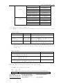
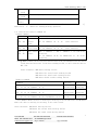
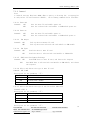
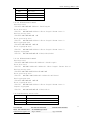
1
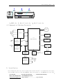
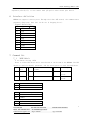
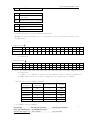
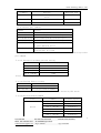
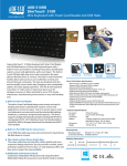
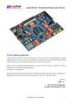
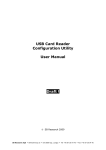
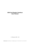
HXTC Technology (HK) Co,.LTD.
MCR200
Multifunctional Reader User Manual V1.0
1.General
MCR200 is an ideal multifunctional reader designed for Banking System. It can encode and
read data of stripe in the bank passbook and card. Obtaining read/write parity functions
together. According to user requirement the device can integrate with IC card and SAM
card module. MCR200 is perfectly choice by bank, stock or etc.
2. Specification
●Voltage: +9V/DC±10% or +5V/DC±10%
●Current :≤300mA
●Sweep speed:10 ~ 100cm/s
●Head life:500,000 times
●IC card slot life(Main)
:200,000 times
●IC card slot life(Sub)
:100,000 times
●SAM card slot life:5,000 times
●Encoding standard:According to IBM、ISO、ANSI
●Encoding density:
Track2:75BPI / 210BPI at optional
Track3:210BPI
●Encoding characters:
210BPI Max length: 104
75BPI Max length
37
●Environmental Requirement: Temp. 0℃~45℃,Humidity 10~90%RH
●Dimension(L*W*H,mm)
:215*64*65
●Weight:
Equipped IC card module: 700g
Without IC card module : 650g
●IC card module according to ISO7811/7816 Standard, Chinese financial IC card
criterion (PBOC2.0) and EMV Standard
3. Appearance
From:Alex.Dai
TEL:086-0755-29372756
MOB:086-139 2840 2917
Ali TradeManager: szhxtc
E-Mail:[email protected]
Skype: dzh0809
FAX:086-0755-29379516
QQ:1176266005
1
HXTC Technology (HK) Co,.LTD.
电源 错 写 读
A、MSRE slot
B、Main IC card slot
C、Sub IC card slot
4. Framework of Working Principle
BEEP
U1
Read
Head
J2
J4
J3
DECODE
Indicator light
Interface
J6
210BPI
Synchronous
Signal
Amplification
shapeing
Process
75BPI
Synchronous
Signal
Amplification
shapeing
Process
U2
Main Control CPU
IC Cad
Interface
J7
210BPI
Serial Port
Expansion Logic
75BPI
Coding
Combinatorial
Logic
+9V or
+5V
Regulator
cell
L7805
+5V
Track 2&3
Writing Driver
DB9F Interface
J1
Write
Head
J5
5. Installation
PC(or Terminal) power off, the included cable connect with PC’s(or Terminal) series port,
and the DB9F connector link with MCR200. After that power on, the MCR200 will test-self,
From:Alex.Dai
TEL:086-0755-29372756
MOB:086-139 2840 2917
Ali TradeManager: szhxtc
E-Mail:[email protected]
Skype: dzh0809
FAX:086-0755-29379516
QQ:1176266005
2
HXTC Technology (HK) Co,.LTD.
if all is ok, then can run the MCR200 normally. If the included cable has series port
expansion ports(A, K), it can connect with pin pad or other series port device.
6. Interface definition
MCR200 can support 3 series ports. Through the 8 bits DIP switch, the communication
parameter (baud rate, data bit) can be set (1 Stopping bit 1).
Signal definition:
Host connector(DB9F)
1
+5V
2
TXD
3
RXD
4
TXD1
5
GNG
6
+9V
7
RXD2
8
TXD2
9
RXD1
7. Command Set
7.1
MSRE Module
7.1.1 Switch setting DIP8
There is a 8bit DIP switch and 1 reset button at the bottom of the MCR200. The DIP
switch is used for default parameter, and the reset button is used for Hard Reset.
SW1
Baud
Rate
SW2
Exit when write delay
ovetime
SW3
Data Length
ON
1200
ON
Exit
ON
8Bits
verify
OFF
9600
OFF
No permission for exit
OFF
7Bit
even
verify
SW4
Character Set
ON
ABA1
OFF
ABA2
SW5
Track2 encoding density set
ON
75 BPI
OFF
210BPI
SW6
Emulation set
ON
BP8902V
From:Alex.Dai
TEL:086-0755-29372756
MOB:086-139 2840 2917
Ali TradeManager: szhxtc
E-Mail:[email protected]
Skype: dzh0809
FAX:086-0755-29379516
QQ:1176266005
no
3
HXTC Technology (HK) Co,.LTD.
OFF
STAR33Ⅲ
SW7
Encoding Format
ON
Track2 is format3, track3
isformat4
OFF
Track2 and track3 is format4
SW8
A/B port Set when power on
ON
A port
OFF
B port
7.1.2 The Character set for reading and writing
MCR200 can select character set I or character set II, the default setting is set
by SW2 switch.
Character setⅠ
ASCII
0
1
2
3
4
5
6
7
8
9
:
#
@
’
=
?
Hex
30
31
32
33
34
35
36
37
38
39
3A
23
40
27
3D
3F
ABA
0
1
2
3
4
5
6
7
8
9
A
B
C
D
E
F
Note: For the characters listed in table, if >1FH, then will be as 30H; <20H,then will
be neglected.
Character set Ⅱ
ASCII
0
1
2
3
4
5
6
7
8
9
:
#
@
’
=
?
Hex
30
31
32
33
34
35
36
37
38
39
3A
23
40
27
3D
3F
ABA
0
1
2
3
4
5
6
7
8
9
A
B
C
D
D
F
Note: 1.For the characters listed in table, if >1FH, then will be as 30H; <20H,then will
be neglected.
2. When = or ’(ASCII) is written in the magnetic card, it will be changed into
D (ABA). When this data is read, D (ABA) will be changed into = (ASCII).
7.1.3 The data record format standard
Standard
Sequence
Initiative
Character
Stop Character
Remark
Standard 1
BA
F
IBMF
Standard 2
BA
F
IBMF
Standard 3
BA
C
IBMC
Standard 4
B
F
ISO
Standard 5
D
F
DIN
Standard 6
B
C
SPECIAL
7.1.4 Common Control Command
From:Alex.Dai
TEL:086-0755-29372756
MOB:086-139 2840 2917
Ali TradeManager: szhxtc
E-Mail:[email protected]
Skype: dzh0809
FAX:086-0755-29379516
QQ:1176266005
4
HXTC Technology (HK) Co,.LTD.
7,1.4.1 Reset and Handshake command
Command
Function
Returning Code
ESC 0 (1b 30)
Soft Reset command, quit read/write
status
No
ESC S (1b 53)
Reset command, reset the MCR200
No
ESC e (1b 65)
Handshake command
ESC y
(1b 79)
7.1.4.2 Select port command
Command
Function
ESC % B (1b 25 42) Select host port, close extend port
ESC % A (1b 25 41) Select extend port A, close host port
ESC % D (1b 25 44) Select extend port D, close host port
ESC % K (1b 25 4B) Select extend port K, close host port
ESC % I (1b 25 49) Select IC card interface, close host port , and
the green LED will be lit
ESC % J (1b 25 4A) Close IC card interface, select host port, and
green LED will be closed
Note: If the extend port is selected, all control commands can not work except select
port command.
7.1.4.3 Initiative encoding position setting
Command
Initiative encoding position
ESC 6 (1B 36)
*12mm
ESC 7 (1B 37)
20mm
ESC 8 (1B 38)
22mm
ESC 9 (1B 39)
25mm
Noted: The default position is 12mm
7.1.4.4 Encoding density setting
Command
Function
ESC L(1b 4c)
Set second track as 75BPI
ESC H(1b 48)
Set second track as 210BPI
Note: The default setting of the second track is defined by DIP switch
7.1.4.5 Record Standard Command
Track
Second
From:Alex.Dai
Command
Standard Sequence
ESC 1 (1B 31)
Standard 1
ESC 2 (1B 32)
Standard 2
ESC 3 (1B 33)
Standard 3
ESC 4 (1B 34)
Standard 4
ESC 5 (1B 35)
Standard 5
ESC Z (1B 5A)
Standard 6
TEL:086-0755-29372756
MOB:086-139 2840 2917
Ali TradeManager: szhxtc
E-Mail:[email protected]
Skype: dzh0809
FAX:086-0755-29379516
QQ:1176266005
5
HXTC Technology (HK) Co,.LTD.
Third
Double
ESC T1(1B 54 31)
Standard 1
ESC T2(1B 54 32)
Standard 2
ESC T3(1B 54 33)
Standard 3
ESC T4(1B 54 34)
Standard 4
ESC T5(1B 54 35)
Standard 5
ESC TZ(1B 54 5A)
Standard 6
ESC B1(1B 42 31)
Standard 1
ESC B2(1B 42 32)
Standard 2
ESC B3(1B 42 33)
Standard 3
ESC B4(1B 42 34)
Standard 4
ESC B5(1B 42 35)
Standard 5
ESC BZ(1B 42 5A)
Standard 6
7.1.5 The first control command set
Note: MCR200 can identify two control command sets. The user can select one of them.
(1)Read Command
Command
Function
Return Data
Read
the
second track
ESC s TK2data
1B 73 TK2data
ESC T ]
(1b 54 5d)
Read
the
third track
ESC s A TK3data ? FS
1B 73 41 TK3data 3F 1C
ESC B ]
(1b 42 5d)
Read double
tracks
ESC s TK2data A TK3data ? FS
1B 73 TK2data 41 TK3data 3F 1C
ESC
]
(1b
5d)
? FS
3F 1C
Note:TK2data means the second track data has been read, and TK 3data means the third
track data has been read. If the data reading failed, it will show the data
as DEL (7f).
(2)Write Command
Command
Function
ESC t
1b
74
TK2data GS ESC \
TK2data 1d 1b 5c
Write the second track
ESC t
1b
74
A TK3data GS ESC \
41 TK2data 1d 1b 5c
Write the third track
ESC t
1b
74
TK2data
TK2data
Write double tracks
A TK3data GS ESC \
41 TK2data 1d 1b 5c
Note: TK2data means the data is waiting for writing in the second track, and TK 3data
means the data is waiting for writing in the third track.
(3)Command for returning the state
ESC j (1b 6a)
This command can return the state of the finish of reading/writing
Function
From:Alex.Dai
Return state code
TEL:086-0755-29372756
MOB:086-139 2840 2917
Ali TradeManager: szhxtc
E-Mail:[email protected]
Skype: dzh0809
FAX:086-0755-29379516
QQ:1176266005
6
HXTC Technology (HK) Co,.LTD.
The second
track
ESC
r
The third
track
ESC
T r p / q / r
(1b 54 72 70/71/72)
ESC
B r p / q / r
(1b 42 72 70/71/72)
Double
tracks
p / q / r
(1b 72
70/71/72)
Note: The last bit in the returning state code is ‘P’that means success; ‘q’
means fail; ‘r’ means not reading/writing operation.
7.1.7 The Second control command set
(1)Read Command
Command
Function
Return Data
ESC r
(1b 72)
Read
second
track
the
ESC s TK2data ? FS ESC state character
1b 73 TK2data 3f 1c 1b state character
ESC p
(1b 70)
Read
the
third track
ESC t TK3data ? FS ESC state character
1b 74 TK3data 3f 1c 1b state character
ESC q
(1b 71)
Read double
tracks
ESC s TK2data ? ESC t TK3data ? FS ESC state
character
1b 73 TK2data 3f 1b 74 TK3data 3f 1c 1b state
character
Note:TK2data means the second track data has been read, and TK 3data means the third
track data has been read. If the data reading failed, it will show the data as
DEL (7f).
State character: 30H
31H
32H
33H
(2)Write Command
means
means
means
means
reading success
the second track reading failed
the third track reading failed
double tracks reading failed
Command
Function
Return Code
ESC w
1b
77
ESC s
1b 73
TK2data ?
FS
TK2data 3f 1c
Write
the
second track
ESC state
character
ESC u
1b
75
ESC t
1b 74
TK3data ?
FS
TK2data 3f 1c
Write
the
third track
ESC state
character
ESC v
1b
76
ESC s TK2data ? ESC t TK3data ? FS
1b 73 TK2data 3f 1b 74 TK2data 3f 1c
Write double
tracks
ESC state
character
Note:TK2data means the data is waiting for writing in the second track, and TK 3data
means the data is waiting for writing in the third track.
State character: 30H means writing success
31H means the second track writing failed
32H means the third track writing failed
From:Alex.Dai
TEL:086-0755-29372756
MOB:086-139 2840 2917
Ali TradeManager: szhxtc
E-Mail:[email protected]
Skype: dzh0809
FAX:086-0755-29379516
QQ:1176266005
7
HXTC Technology (HK) Co,.LTD.
33H means double tracks writing failed
34H means the write command or data format is illegal
7.2 IC card module
7.2.1 Communication protocol
There are two protocols to transfer::
(1) TLP224(Intersected character)protocol
The format when transfer of information is right:
<ACK> <LN> <MESSAGE> <LRC>
ACK:
60H,State right command or status
LN:
State the length of info ( Command or status code)
MESSAGE: Command or status code
LRC:
The longitudinal redundant character . The value of XOR with <ACK>,
<LN>, <MESSAGE>.
The format when transfer of information is wrong:
< NACK > <LN> <LRC>
NACK:
E0H,State error command or status
LN:
00H
LRC:
E0H
Sound code file excute the following process:
The transferring byte will be divided up two ASCII codes, for example, transfer
the “3AH”, the sound code file will send 33 and 41H, so that can avoid collision with
the system controlling characters. And append the stopping character (EOT) at the end.
EOT=03H
(2)BLOCK PROTOCOL
Format
NAD
PCB
LEN
DAT
EDC
NAD:Initiative and objective identifier
Identifier
7
6
5
4
3
2
1
0
High half byte state objective identifier, low half byte state initiative
identifier.
Host=2;IC card reader/writer=4;
PCB:State the type of block, the format will be decide by the type, describe as
following:
Type1:I – Blocks(Information Blocks)Support the data exchange between initiative
and objective.
Format:
Bit 7
6
5
4
3
2
1
0
0
S
From:Alex.Dai
0
0
0
0
0
TEL:086-0755-29372756
MOB:086-139 2840 2917
Ali TradeManager: szhxtc
E-Mail:[email protected]
Skype: dzh0809
0
FAX:086-0755-29379516
QQ:1176266005
8
HXTC Technology (HK) Co,.LTD.
Sequence bit
Rest will not use
The six bit is sequence, it will be set “0” when power on, the sequence bit will
be 0 when the initiative send the first I – Block, after that the sequence bit
will be add 1 when transferring next I – Block.
The sequence bit will be the same as the initiative.
Type2:R – Blocks(Receive Ready Blocks)
Format:
Bit
7
6
5
4
3
2
1 0
1
0
0
S
0
0
`E
V
1 = XOR EDC Error
1 = Other error
1 = Sequence
Type3:S – Blocks(Supervisory Blocks)
S – Blocks Ask for the objective to set the sequence as 0, and return to
state transfer over.
Bit 7
6
5
4
3
2
1
0
Synchronization require
1
Bit
7
1
1
6
1
0
5
1
0
0
0
4
3
2
0
0
0
0
1
0
0
0
Synchronization responses
0
LEN:the length of the info.
DAT:the transferring info(command block or returning status)
EDC:The longitudinal redundant character . The value of XOR with <ACK>, <LN>,
<MESSAGE>.
For example:Pick up 4 stochastic data from main IC card:
TLP224 Format:
Power on,command:12H
The head of command: 60H 01H 12H 73H
The format of intersect transferring data:36H 30H 30H 31H 31H 32H 37H 33H 03H
To pick up 4 stochastic data:00H 84H 00H 00H 04H
The head of command: 60H 06H 13H 00H 84H 00H 00H 04H F5H
The format of intersect transferring data:36H 30H 30H 36H 31H 33H 30H 30H 38H 34H
30H 30H 30H 30H 30H 34H 46H 35H 03H
BLOCK PROTOCOL Format:
Transfer data:
Power on,command:12H
Format:42H 00H 01H 12H 51H
To pick up 4 stochastic data:00H 84H 00H 00H 04H
Format:42H 40H 06H 13H 00H 84H 00H 00H 04H 97H
From:Alex.Dai
TEL:086-0755-29372756
MOB:086-139 2840 2917
Ali TradeManager: szhxtc
E-Mail:[email protected]
Skype: dzh0809
FAX:086-0755-29379516
QQ:1176266005
9
HXTC Technology (HK) Co,.LTD.
7.2.2 Command
Note:
1、Default setting: Baud rate 9600,8Bit no parity,1 Starting bit, 1 stopping bit
2、Only Select IC card Interface(ESC%I), the following command can be available.
7.2.2.1 Power Off
Command: 11H
19H
have the main IC card module power off
have the selected sub card module or SAM module power off
7.2.2.2 Power On
Command: 12H
1AH
have the main IC card module power on
have the selected sub card module or SAM module power on
7.2.2.3 ISO Output
Command: 13H
Pick up data from main IC card
1BH
Pick up data from selected sub card module or SAM module
7.2.2.4 ISO Input
Command: 14H
Send the data to main IC card
1CH
Send the data to selected sub card module or SAM module
7.2.2.5 APDU Data Envelopment Exchange
Command: 15H
Send APDU data to main IC card, and obtain the response
1DH
Send APDU data to selected sub card module or SAM module, and obtain
the response
7.2.2.6 Select and define the type of main IC card
Command:17H T 00H
Description for the parameter “T”:
Hex
Type of main IC card
02H
CPU card
08H
SLE4418/4428(GPM8K)
09H
SLE4432/4442(GPM2K or PCB2032/2042)
7.2.2.7 Select and define the type of sub IC card(or SAM card)
Command:1FH T N
Description for the parameter “T”:
Hex
Type of main IC card
02H
CPU card
08H
SLE4418/4428(GPM8K)
09H
SLE4432/4442(GPM2K or PCB2032/2042)
Description for the parameter “N”:
From:Alex.Dai
TEL:086-0755-29372756
MOB:086-139 2840 2917
Ali TradeManager: szhxtc
E-Mail:[email protected]
Skype: dzh0809
FAX:086-0755-29379516
QQ:1176266005
10
HXTC Technology (HK) Co,.LTD.
N(Hex)
Card for operation
01H
Sub card
02H
SAM card 1
03H
SAM card 2
04H
SAM card 3
7.2.2.8 SLE4432/4442 Command
Read data area:
(ISO OUT)00H B0H 00H(Address)
(Read Length)
Write data area:
(ISO IN) 00H D0H 00H(Address)
(Write Length)
(Data0..Data n)
Read protecting area:
(ISO OUT)00H B0H 80H 00H 04H
Write protecting area:
(ISO IN) 00H D0H 80H(Address)
(Write Length)
(Data0..Data n)
Read cryptogram area
(ISO OUT)00H B0H C0H 00H 04H
Write cryptogram area:
(ISO IN) 00H D0H C0H(Address)
(Write Length)
(Data0..Data n)
Compare cryptogram:
(ISO IN) 00H 20H 00H 00H 03H(Code3,Code2,Code1)
7.2.2.9 SLE4418/4428 Command
Read data area:
(ISO OUT)00H B0H(AddressH)
(AddressL)
(Read Length)
Write data area:
(ISO IN) 00H D0H(AddressH)
(AddressL)
(Write Length)
(Data0..Data n)
Read protecting area:
(ISO OUT)00H B0H(80H+AddressH)00H 20H
Write protecting area:
(ISO IN) 00H D0H(80H+AddressH)
(AddressL)01H(Data)
Read cryptogram area
(ISO OUT)00H B0H C0H 00H 03H
Write cryptogram area:
(ISO IN) 00H D0H C0H(Address)
(Write Length)
(Data0..Data n)
Compare cryptogram:
(ISO IN) 00H 20H 00H 00H 02H(Code2,Code1)
7.2.2.10 Returning status value
Hex
Description
00H
Successfully execute for R/W operation
01H
Unknown driving or command
03H
The length of parameter is error
From:Alex.Dai
TEL:086-0755-29372756
MOB:086-139 2840 2917
Ali TradeManager: szhxtc
E-Mail:[email protected]
Skype: dzh0809
FAX:086-0755-29379516
QQ:1176266005
11
HXTC Technology (HK) Co,.LTD.
05H
Returning info overflow
09H
Communication protocol error
10H
Card resetting response erro
15H
Card power off
A2H
Halt connect for overtime
EEH
The module is busy
F8H
Card short circuit
FBH
Not insert card
7.2.2.11 Set Operating Mode
This command selects the operating mode of treatment of an asynchronous card.
The following two modes exist:
• Generic ISO mode
• EMV-compliant mode
Some commands are not allowed in EMV mode, while others undergo changes in their
behavior.
Format
17h 00h Mode Main slot
1Fh 00h Mode Auxiliary slot
Where:
Mode: Represents the operating mode to be selected
47h selects the generic ISO mode
45h selects the EMV-compliant mode
00h returns the currently selected mode
Response
S Mode
Where:
Mode: Represents the currently selected mode
47h = generic ISO mode
45h = EMV-compliant mode
8. Maintenance
8.1 Daily maintenance
Clean
Head
Magnetic
Clean encoder
Use special cleaning card that is soaked by industrial alcohol
to clean head for 5-10 times.
Use special cleaning card that is soaked by industrial alcohol
to clean the gear of encoder for 5-10 times.
8.2 Common problem and solution
Common Problem
From:Alex.Dai
Solution
TEL:086-0755-29372756
MOB:086-139 2840 2917
Ali TradeManager: szhxtc
E-Mail:[email protected]
Skype: dzh0809
FAX:086-0755-29379516
QQ:1176266005
12
HXTC Technology (HK) Co,.LTD.
1. W/R error
Clean the head and encoder
2. No response when R/W
MSRE or IC module
Check the cable connect and the setting for COMM.
From:Alex.Dai
TEL:086-0755-29372756
MOB:086-139 2840 2917
Ali TradeManager: szhxtc
E-Mail:[email protected]
Skype: dzh0809
FAX:086-0755-29379516
QQ:1176266005
13