1
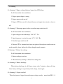
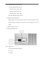
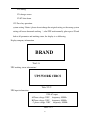
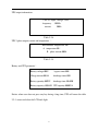
UNINTERRUPTIBLE POWER SUPPLY
DS-10 to 80KVA
USER’S MANUAL
C
Coonntteenntt
1.Products introduction ---------------------------------------------1
2.Operation demand -------------------------------------------------1
3.Notices ------------------------------------------------------------1
4.Working principle --------------------------------------------------2
5.Front panel ----------------------------------------------------------7
6.Installation ----------------------------------------------------------8
7. Specification ------------------------------------------------------11
8. Alarming -----------------------------------------------------------14
9.UPS start up process -----------------------------------------------15
10.UPS maintenance shutdown process---------------------------16
11. Urgency shutdown process--------------------------------------16
12.Front panel introduction------------------------------------------16
1
Products introduction
1
DS (three phase in and one phase out) series UPS is large power and true on–line
UPS with range from 10KVA to 80KVA, which adopts advanced digital design, high
speed 16–bit chip, ASIC, DDC and large power IGBT&SCR, and shows large
capacity, high stability and super performance compared with usual models on the
market. All the products have integrated the latest hardware and powerful software in
itself, which could provide optimum pure power to integrated server center. This
system supports several units connected in parallel through unique control
technology.
Operation demand
2
Please read carefully the user manual before using machine.
This manual must be understood and conserved by professional.
This manual does not introduce the detail specification.
This manual just suit to DS (three phase in and one phase out) series UPS.
3
Notices
3.1 Make sure relevant power input/output/battery/cable.
3.2.it must be steady grounding system.
3.3. There are a lot of high-voltage energy storage device in Machine, please don't
open case and check, otherwise cause danger to lift, accept the consequences by
oneself. The operator must understand the electrician basic knowledge and pore
over the operation instructions.
3.4. Without permission, can't dismantle various kinds of connection cables
without authorization.
3.5. Because this product is greater in volume, weight is relatively heavy, can't move
2
at will, must not split and shake strongly Move, and keep ventilating it well.
3.6. In case of electrification, can't go to discharge the dust; Handy wet towel go to
wipe and get rid of the dirt.
3.7. The battery must be changed by the professional and technical personnel, the
battery changed out must deliver special circulation and give a new lease of life to the
organization to deal with . The battery is " poisonous waste material "
3.8. UPS is not used when being installed a long time, the battery disposed will
discharge automatically, at the same time the automatic consumption that chemical
energy of the battery, at 25 degrees Centigrade according to the environmental climate
around,, the battery must be charged in every three months, if the temperature is
greater than 30 degrees Centigrade, the battery should be charged once every two
months . Only need to start UPS while charging, and run at least for 24 hours under the
normal work pattern.
4
working principle
4.1. DS 3/1 series UPS adopts advanced digital design,
steadily
improved MTBF and
one lone main control panel control all system. Which adopts
microprocessor control and ensure that machine can work steadily and reliably.
3
Besides, UPS others parts: invert transformer, input inductance, IGBT, silicon controlled
and switch.
4.2.Standard UPS principle
4.3.Mains inverter principle
After AC input turn to DC filter through rectifier, then inverter invert through
SPWM and output AC.
4
4.3.1.Normal inverter model
Battery have been recharge full, after AC rectifier, then inverter output.
4.3.2. Inverter normally, and battery recharge working model
battery voltage is low, after AC inverter, on one hand it will charge, on the other
inverter output.
4.3.3. AC input failure, battery-working model:
AC input is failure, battery inverter and supply power.
5
4.3.4.Bypass output working model:
There is AC input, but inverter has been closed, meantime, output is supplied bypass.
4.4. Function module
4.4.1.Rectifier
Protection short circuit rectifier switch
Lightning arrestor
6/12 Plus rectifier
Input inductance
Battery temperature compensate
6
Battery floating charging
Battery timing balanced charging.
The input of rectifier can be limited in rated numerical value, at the same
time , battery recharge in constant current, constant voltage, expert engineer can
change rectifier working through setting parameter.
4.4.2.Inverter
Inverter output isolation transformer.
3 Phase PWM inverter bridge.
Current sampling
Voltage sampling
Feedback control
Self–testing
Hardware sense
Protection circuit
7
5
Front panel introduction
LED statue display-----it indicates working statue
LCD display------it indicates Various kinds of data
Fuse pedestal ------it is used by power supply, sampling, fan and so on .
Input rectifier switch ------Control rectifier input
Bypass switch ------Control bypass input.
Output switch ------Control output
Battery switch ------Control battery input
Maintenance bypass switch ------Control AC bypass (just use it when
maintenance)
Line bank------Connect input, output, battery and grounding.
8
6
INSTALLATION:
6.1.Installation environment
Temperature 0 ~+40
Relative humidity 30%~90%
Altitude ≤1000M
Installation environment dimension L×W×H
1500×1000×2000
Board pressure 2000KG/M2
The indoor environment demanded is as following:
No dust
Appropriate indoor temperature: please operate UPS in 0~40 ,
But it is 0 when start, the idea operation temperature is 25 .
There should be a good heat dissipation system, the following is a feasible
method:
A: Natural ventilating system: Only suitable for low heat and vast space.
B: man - made ventilating systems: Need to install the air conditioner when
exceeds the peripheral temperature (TE) in chassis temperature (TA). As the TE and
TA is close, the capacity of the heat distribution system will increase.
6.2. Check before installation
Unpack the equipment and inspect again to determine if any external or internal
damage has occurred.
Opening the main entrance, meantime, please check if all switches are
9
disconnection.
6.3.Installation site
Please place the UPS in the place where keeps good ventilation, rear panel of
UPS and two side faces should keep more than 80cm away from the wall.
Do not lay goods on the UPS.
It must have enough room to Overhaul in the front of equipment and above.
Battery box of equipment must keep enough position on right-hand side for
battery overhaul.
Power line must be connected from bottom of machine.
6.4.Terminal connection diagram:
E
R
S
T
N
N
Input
L
Output
+
_
battery
E
Grounding
Before UPS is not being installed, please disconnect all switches.
Left: R S T N connect three phase input phase line and median line ;
Right :N
L connect one phase output phase line and median line;
E connect earth line + - connect battery positive pole and negative pole.
10
6.5.UPS three output system 10-80KVA cable specification:
Input
Capacity
R
S
T
Output
N
E
(unit: mm2)
Battery
T
N
+
-
10KVA
6
6
6
6
6
12
12
10
10
20KVA
10
10
10
10
10
20
20
16
16
30KVA
16
16
16
16
16
35
35
25
25
40KVA
25
25
25
25
16
50
50
35
35
60KVA
35
35
35
35
16
75
75
50
50
80KVA
40
40
40
40
16
100 100 75
75
6.6 Battery connection
Opening battery pack.
Installation battery on the corresponding position and connecting the good
battery connecting wire
6.7.connection inspection
connect all input/output/battery/wire check under matters:
Whether all battery connecting wires join correctly and keep in touch well,
Input, output, the earth connection has already been connected in the
corresponding wiring on the equipment is arranged correctly,
The voltage of input end, frequency, phase should keep the same with voltage
of bypass, frequency, and phase.
7 Specification
11
Model
DS10K
DS15K
DS20K
DS30K
DS40K
DS50K
DS60K
DS80K
VA rating
10KVA
15KVA
20KVA
30KVA
40KVA
50KVA
60KVA
80KVA
Working mode and principle
True on-line, static bypass(uninterrupted switch), double conversion, input & output complete
isolation
AC input
Phase
3 phase + N + G
Voltage
380V ± 25%
Frequency
50/60Hz ± 5%
Power factor
0.92 (with input filter)
Soft start
0 – 100% 5 s (non-shock current)
Bypass input
Phase
Single phase
Voltage
220V ± 20%
Frequency
50/60Hz ± 5%
Transfer time
0 ms, Inverter / bypass (overload)
DC system
360V (rated voltage)
DC voltage
Current
315V (end voltage)
25A
38A
51A
76A
101A
126A
152A
203A
AC output
Phase
Single phase
Voltage
220V ± 1%(stable load); 220V ± 5%(load fluctuation)
Frequency
50-60Hz ± 0.05% (battery mode)
Power factor
0.8
Wave form
Pure sine wave
Harmonic
distortion
<3%(linear load); <5%(non-linear load)
Dynamic
Dynamic load voltage instantaneous change(0-100%)
Time
± 5%
Instantaneous recover time <10 ms
Overload
125% for 1 min; 150% for 1 s
Cooling
Force ventilation (temperature control mode)
System
Efficiency
91%
91%
92%
92%
93%
Communication
RS232 or SNMP
Temperature
0-40
Humidity
Working height
Noise(db)
Dimension(mm)
93%
93%
95%
(working)
30-90%
< 1000m (1% power reduce per 100 m height rising, Max. 4000m)
48-60
53-65
430×683×910
430×800×1050
12
55-65
750×720×1450
750×860×1600
8.Alarming:
8.1 Alarming 1 Bypass voltage failure or bypass fuse SCR failure.
It will alarm under these conditions:
1. Bypass input voltage is wrong.
2. Bypass input switch cut off.
3. Bypass SCR fuse cut off or burned because of output short circuit or fuse cut
off.
8.2 Alarming 2 Main input power failure or rectifier input switch cut off.
It will alarm under these conditions:
1. Input voltage is not in the range 184 287 VAC.
2. Input frequency is not in the range 47.5 54.5 Hz.
3. Rectifier input switch cut off.
4. Because UPS is abnormal and cause one phase of three phase rectifier can not
work normally, please find out the failure thought consult contents.
8.3Alarming 3 Battery low voltage
It will alarm under these conditions
1. Battery voltage is too low.
2. The time battery running is shorter than setting time.
8.4 Alarming 4 Battery discharge
When battery discharge, it will alarm at once, after 2 minutes, alarm will stop.
Once battery discharge is up to battery final voltage, alarm again.
8.5 Alarming 5 Output overload.
When load power is bigger than rated output voltage, namely, more than 100 % if
13
load current is over big, UPS will alarm. When UPS alarm, it needs to reduce load
capacity. Or UPS will turn to bypass, we get the time depend on over load value’s
inverse ratio.
8.6 Alarming 6 Temporality bypass working
It indicates bypass supply power; UPS will turn to normally run statue (inverter
supply power). There are some conditions under this temporality statue, for example,
overload, after bypass supply power, UPS is waiting for power supplied by inverter.
8.7 Alarming 7 Bypass output overload
If overload time is too long, for example, overload 125%, inverter can supply power
1min. then turn to bypass. UPS will renew normal running statue.
8.8 Alarming 8 High temperature or fan failure
When control system of UPS, inverter power module or rectifier power module is
over temperature because of high temperature or fan failure, UPS turn to bypass.
9 UPS start up process
It must be operated to obey these sequence, thought there is battery switch in UPS.
Start up UPS
9.1.Open input rectifier switch Up .
9.2.Open bypass switch UP
9.3.After battery low voltage indicator crust out, then open battery switch. When UPS
is no any alarm statue indicator, bypass will turn to inverter statue.
Notice it will display alarming information about the wrong phase sequence if
rectifier switch is not cut off, at this time, please press F1 and silence, carry out
UPS start up process.
14
10 UPS maintenance shut down process
10.1.open maintenance switch up
10.2.close battery switch down
10.3.close rectifier switch up
10.4.close bypass switch down
10.5.close UPS output switch down
11. Emergency shut down process
When it happens to fire, electric shock, electric arc or other dangerous. user can
read this process and operate, but it maybe cause the dangerous that no AC
output.
——Make all switches cut off
12 Front panel introduction
12.1 key introduction:
F1: Functional grouping /silencing
F2: start up
F3: testing
15
F4: setting
F5: change screen
F1+F2 shut down.
12.2 Press key operation:
system setting Notice please do not change the original setting, or the wrong system
setting will cause abnormal working
, after UPS work normally, please press F5 and
look at all parameter and working statue, the display is as following:
Display company information
BRAND
Tble2-2-1
UPS working statue information
UPS WORK CIRCS
Table 2-2-2
UPS input information
UPS AC input:
A Phase voltage: 230V frequency: 50.0Hz
B Phase voltage: 230V frequency: 50.0Hz
C phase voltage: 230V frequency: 50.0Hz
Table 2-2-3
16
UPS output information:
UPS AC ouput: voltage: 230V
frequency: 50.0Hz
current:
000A
Table 2-2-4
UPS 3 phase output current and temperature
Environment temperature :00
A temperature:00
B phase current:000A
Table 2-2-5
Battery and UPS parameter
Battery voltage:000V
bypass times:000
Charge current:00.0A
discharge times:000
Battery quantity:00PCS
discharge time :00:00H
Battery capacity :000AH UPS capacity:000KVA
Notice: when user does not press any key during a long time, UPS will renew the table
2-2-1 screen and close the LCD back light.
17