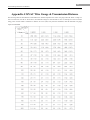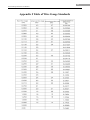
1
Network IR Speed Dome User Manual V3.0.1 1 Network IR Speed Dome User Manual Thank you for purchasing our product. If there are any questions, or requests, please do not hesitate to contact the dealer. This manual applies to Network IR Speed Dome . This manual may contain several technical incorrect places or printing errors, and the content is subject to change without notice. The updates will be added to the new version of this manual. We will readily improve or update the products or procedures described in the manual. DISCLAIMER STATEMENT “Underwriters Laboratories Inc. (“UL”) has not tested the performance or reliability of the security or signaling aspects of this product. UL has only tested for fire, shock or casualty hazards as outlined in UL’s Standard(s) for Safety, UL60950-1. UL Certification does not cover the performance or reliability of the security or signaling aspects of this product. UL MAKES NO REPRESENTATIONS, WARRANTIES OR CERTIFICATIONS WHATSOEVER REGARDING THE PERFORMANCE OR RELIABILITY OF ANY SECURITY OR SIGNALING RELATED FUNCTIONS OF THIS PRODUCT.” 2 Network IR Speed Dome User Manual Regulatory Information FCC Information FCC compliance: This equipment has been tested and found to comply with the limits for a digital device, pursuant to part 15 of the FCC Rules. These limits are designed to provide reasonable protection against harmful interference when the equipment is operated in a commercial environment. This equipment generates, uses, and can radiate radio frequency energy and, if not installed and used in accordance with the instruction manual, may cause harmful interference to radio communications. Operation of this equipment in a residential area is likely to cause harmful interference in which case the user will be required to correct the interference at his own expense. FCC Conditions This device complies with part 15 of the FCC Rules. Operation is subject to the following two conditions: 1. This device may not cause harmful interference. 2. This device must accept any interference received, including interference that may cause undesired operation. EU Conformity Statement This product and - if applicable - the supplied accessories too are marked with "CE" and comply therefore with the applicable harmonized European standards listed under the Low Voltage Directive 2006/95/EC, the EMC Directive 2004/108/EC. 2002/96/EC (WEEE directive): Products marked with this symbol cannot be disposed of as unsorted municipal waste in the European Union. For proper recycling, return this product to your local supplier upon the purchase of equivalent new equipment, or dispose of it at designated collection points. For more information see: www.recyclethis.info. 2006/66/EC (battery directive): This product contains a battery that cannot be disposed of as unsorted municipal waste in the European Union. See the product documentation for specific battery information. The battery is marked with this symbol, which may include lettering to indicate cadmium (Cd), lead (Pb), or mercury (Hg). For proper recycling, return the battery to your supplier or to a designated collection point. For more information see: www.recyclethis.info. 3 Network IR Speed Dome User Manual Safety Warnings and Cautions Please pay attention to the following warnings and cautions: Hazardous Voltage may be present: Special measures and precautions must be taken when using this device. Some potentials (voltages) on the device may present a hazard to the user. This device should only be used by Employees from our company with knowledge and training in working with these types of devices that contain live circuits. Power Supply Hazardous Voltage: AC mains voltages are present within the power supply assembly. This device must be connected to a UL approved, completely enclosed power supply, of the proper rated voltage and current. No user serviceable parts inside the power supply. System Grounding (Earthing): To avoid shock, ensure that all AC wiring is not exposed and that the earth grounding is maintained. Ensure that any equipment to which this device will be attached is also connected to properly wired grounded receptacles and are approved medical devices. Power Connect and Disconnect: The AC power supply cord is the main disconnect device to mains (AC power).The socket outlet shall be installed near the equipment and shall be readily accessible. Installation and Maintenance: Do not connect/disconnect any cables to or perform installation/maintenance on this device during an electrical storm. 4 Network IR Speed Dome User Manual Power Cord Requirements: The connector that plugs into the wall outlet must be a grounding-type male plug designed for use in your region. It must have certification marks showing certification by an agency in your region. The connector that plugs into the AC receptacle on the power supply must be an IEC 320, sheet C13, female connector. See the following website for more information http://kropla.com/electric2.htm. Lithium Battery: This device contains a Lithium Battery. There is a risk of explosion if the battery is replaced by an incorrect type. Dispose of used batteries according to the vendor’s instructions and in accordance with local environmental regulations. Perchlorate Material: Special handling may apply. See www.dtsc.ca.gov/hazardouswaste/perchlorate. This notice is required by California Code of Regulations, Title 22, Division 4.5, Chapter 33: Best Management Practices for Perchlorate Materials. This device includes a battery which contains perchlorate material. Taiwan battery recycling: Please recycle batteries. Thermal and Mechanical Injury: Some components such as heat sinks, power regulators, and processors may be hot; care should be taken to avoid contact with these components. Electro Magnetic Interference: This equipment has not been tested for compliance with emissions limits of FCC and similar international regulations. This device is not, and may not be, offered for sale or lease, or sold, or leased until authorization from the United States FCC or its equivalent in other countries has been obtained. Use of this equipment in a residential location is prohibited. This equipment generates, uses and can radiate radio frequency energy which may result in harmful interference to radio communications. If this equipment does cause harmful interference to radio or television reception, which can be determined by turning the equipment on and off, the user is required to take measures to eliminate the interference or discontinue the use of this equipment. Lead Content: Please recycle this device in a responsible manner. Refer to local environmental regulations for proper recycling; do not dispose of device in unsorted municipal waste. 5 Network IR Speed Dome User Manual Safety Instruction These instructions are intended to ensure that the user can use the product correctly to avoid danger or property loss. The precaution measure is divided into ‘Warnings’ and ‘Cautions’: Warnings: Serious injury or death may be caused if any of these warnings are neglected. Cautions: Injury or equipment damage may be caused if any of these cautions are neglected. Warnings Follow these safeguards to prevent serious Cautions Follow these precautions to prevent potential injury or death. injury or material damage. Warnings 1. In the use of the product, you must strictly comply with the electrical safety regulations of the nation and region. 2. Please use the power adapter which is provided by registered manufacturer. The power requirement should be either AC24V/3A or DC12V/3A depending on models. 3. Do not connect several devices to one power adapter as an adapter overload may cause over-heating and can be a fire hazard.If use the POE as the power supply, please make sure that the POE Switch have the sufficient power. 4. Please make sure that the plug is firmly inserted into the power socket. 5. When the product is installed on a wall or ceiling, the device should be firmly fixed. 6. If smoke, odor, or noise rise from the device, turn off the power at once and unplug the power cable, then contact the service center. 7. If the product does not work properly, please contact your dealer or the nearest service center. Never attempt to disassemble the camera yourself. (We shall not assume any responsibility for problems caused by unauthorized repair or maintenance.) Cautions 1. Do not drop the dome or subject it to physical shock, and do not expose it to high electromagnetism radiation. Avoid the equipment installation on vibrations surface or places subject to shock (ignorance can cause equipment damage). 2. Do not place the dome in extremely hot, cold (the operating temperature shall be -30°C ~ +65°C), dusty or damp locations, or fire or electrical shock will occur otherwise. 3. The dome cover for indoor use shall be kept from rain and moisture. 4. Exposing the equipment to direct sun light, low ventilation or heat source such as heater or radiator is forbidden (ignorance can cause fire danger). 5. Do not aim the camera at the sun or extra bright places. A blooming or smear may occur otherwise (which is not a malfunction however), and affecting the endurance of CCD at the same time. 6. Please use the provided glove when open up the dome cover, avoid direct contact with the dome cover, because the acidic sweat of the fingers may erode the surface coating of the dome cover. 7. Please use a soft and dry cloth when clean inside and outside surfaces of the dome cover, not to use alkaline detergents. 8. Improper use or replacement of the battery may result in hazard of explosion. Replace with the same or equivalent type only. Dispose of used batteries according to the instructions provided by the battery manufacturer. 6 Network IR Speed Dome User Manual Table of Contents Chapter 1 Brief Introduction........................................................................................................................................ 7 1.1 Description..................................................................................................................................................... 7 1.2 Outline ........................................................................................................................................................... 7 1.3 Functions ....................................................................................................................................................... 7 1.4 Features.......................................................................................................................................................... 9 1.5 Default IP, User Name and Password .......................................................................................................... 10 Chapter 2 Operation Instructions................................................................................................................................11 2.1 Power-up Action ...........................................................................................................................................11 2.2 Presets with Special Functions .....................................................................................................................11 2.3 Label Display............................................................................................................................................... 12 Chapter 3 Access to Network Speed Dome ............................................................................................................... 13 3.1Access through IE......................................................................................................................................... 13 3.1.1 Preview ..................................................................................................................................................... 13 3.1.2 Parameters Configuration ......................................................................................................................... 17 3.1.2.1 Local Configuration....................................................................................................................... 17 3.1.2.2 Remote Configuration.................................................................................................................... 18 3.2Access by Client Software............................................................................................................................ 44 3.2.1 Configuration through Client Software ............................................................................................ 44 3.2.2 3D Intelligent Positioning................................................................................................................. 49 3.2.3 Presets ............................................................................................................................................... 51 3.2.4 Patrols ............................................................................................................................................... 53 3.3 Configuration by DS-9000 Series DVR ...................................................................................................... 54 3.4 Search and Modify IP by SADP .................................................................................................................. 55 3.4.1 Search active devices online ............................................................................................................. 55 3.4.2 Modify device information ............................................................................................................... 56 3.4.3 Resume default password ................................................................................................................. 57 3.5 Access by WAN ........................................................................................................................................... 57 Appendix 1 Network Cable Connection.................................................................................................................... 59 Appendix 2 Lightning & Surge Protection ................................................................................................................ 60 Appendix 3 RS485 Bus Connection .......................................................................................................................... 61 Appendix 4 24VAC Wire Gauge & Transmission Distance ...................................................................................... 64 Appendix 5 Table of Wire Gauge Standards.............................................................................................................. 65 7 Network IR Speed Dome User Manual Chapter 1 Brief Introduction 1.1 Description Integrating the network remote monitoring capability with the functions of the high speed dome, the Network High Speed Dome is a new product model which features easy installation and operation and facilitated wiring design. With built-in video server, the Network Speed Dome is capable of providing the following new features: real-time video stream compressed and then transmitted via network to different clients simultaneously; based on Ethernet, and analog video output supported; TI DAVINCI processing chip and platform adopted to ensure high reliability and stability of performance; H.264 compression adopted to effectively save network transmission bandwidth and HD storage space; dynamic configuration of encoding parameters; PPPoE, DHCP, UDP, MCAST and TCP/IP protocols supported; bidirectional voice talk, OSD overlay and RS-485 serial port control; built-in Web Server allows control of speed dome via IE browser; main stream and sub stream selectable for transmission; local and remote alarm response actions; multi-zone motion detection with different sensitivity levels configurable; remote integrated storage based on IPSAN and NAS; and watermark technology adopted for stream data to prevent unauthorized operation of the record files, etc. The Network High-definition Speed Dome can be widely applied to various monitoring scenes such as the river, forest, road, railway, airport, harbor, oil field, sentry, plaza, park, scenic spot, street, station, stadium, etc. 1.2 Outline Network IR Speed Dome 1.3 Functions Keyboard Control The pan/tilt movement and zoom actions of dome can be controlled by the control keyboard, DVR, matrix, etc. Limit Stops The dome can be programmed to move within the limit stops (left/right, up/down) which are configurable by the control keyboard, DVR or client application software. 8 Network IR Speed Dome User Manual Auto Scan The dome provides 5 scanning modes: pan scanning, tilt scanning, frame scanning, random scanning and panorama scanning. The scanning speed can be set by menu from level 1 to 40, with the corresponding speed ranging from 1°/second to 40°/second. Preset Freeze Frame This feature freezes the scene on the monitor when going to a preset. This allows for smooth transition from one preset scene to another and also guarantees that masked area will not be revealed when going to a preset. Presets Each of the user-definable presets can be programmed to use pan, tilt, camera settings and other settings. When preset is called, the dome will automatically move to the defined position. User is allowed to add, modify, delete and call each preset. Label Display The on-screen label of the preset title, azimuth/elevation, zoom and other operations can be programmed by menu and displayed on the monitor. Auto Flips In manual tracking mode, when a target object goes directly beneath the dome, The video will automatically flips 180 degrees in horizontal direction to maintain continuity of tracking. This function can also be realized by auto mirror image depending on different camera models. Privacy Mask The privacy mask allows a user to program user-defined areas that cannot be viewed by the operator of the dome system. A masked area will move with pan and tilt functions and automatically adjust in size as the lens zooms telephoto and wide. 3D Intelligent Positioning The speed dome can be controlled with the 2 buttons and scroll of mouse can be used under PRIVATE-Code protocols with devices and client software. Use the left key of mouse to click on the desired position in the video image and drag a rectangle area in the lower right direction, then the dome system will move the position to the center and allow the rectangle area to zoom in. Use the left key of mouse to drag a rectangle area in the upper left direction to move the position to the center and allow the rectangle area to zoom out.. Note: Please refer to Section 4.2.2 3D Intelligent Positioning for the specific instructions. Proportional Pan/Tilt Proportional pan/tilt automatically reduces or increases the pan and tilt speeds in proportion to the amount of zoom. At telephoto zoom settings, the pan and tilt speeds will be slower for a given amount of joystick deflection than at wide zoom settings. This keeps the image from moving too fast on the monitor when there is a large amount of zoom. Auto Focus The auto focus enables the camera to focus automatically to maintain clear video images. IR Cut Filter The IR cut filter can be set to Auto, Day and Night. In auto mode, the camera is capable of automatically switching Black & White mode (Night) and Color mode (Day) with regard to environment lightening conditions. In manual switch mode, user can increase sensitivity in low light conditions by switching to Black & White mode, while the Color mode is preferred in normal lighting conditions. Low Light Electronic Shutter The shutter speed will automatically slow down in low illumination conditions to maintain clear video images by extending the exposure time. The feature can be enabled/disabled by the menu. Backlight Compensation (BLC) If a bright backlight is present, the subjects in the picture may appear dark or as a silhouette. Backlight compensation (BLC) enhances objects in the center of the picture. The dome uses the center of the picture to adjust the iris. If there is a bright light source outside of this area, it will wash out to white. The camera will adjust the iris so that the object in the sensitive area is properly exposed. Wide Dynamic Range (WDR) 9 Network IR Speed Dome User Manual When the Wide Dynamic Range (WDR) function is on, the dome is able to balance the brightest and darkest sections of a scene to produce a picture that is better balanced in lighting and provides more details. White Balance (WB) This feature automatically processes the viewed image to retain color balance over a color temperature range. The default setting for white balance is AUTO. Patrol The high speed dome provides up to 8 patrols. In each patrol, user is allowed to specify the scanning track by a group of user-defined presets, with the scanning speed between two presets and the dwell time at the preset separately programmable. Pattern A pattern is a memorized, repeating series of pan, tilt, zoom, and preset functions that can be recalled with a command from a controller or automatically by a configured function (alarm, park, time task, or power-up). By default the focus and iris are in auto status during the pattern is being memorized. Power Loss Position The dome supports the power loss position capability with the predefined dwell time. It allows the dome to resume its previous position after power is restored. Alarm Response Action The speed dome supports 7 alarm inputs which can be set to NO (normally open), NC (normally closed). Upon having received the alarm input signal, the dome will automatically activate a user-defined action, which can be programmed to patrol, pattern or preset callup. Note: This feature varies depending on camera models. AUX Output An auxiliary output is a configurable signal from the dome back box that can trigger another device to operate. The dome provides 1 auxiliary outputs: AUX1/AUX2. The auxiliary output type can be set to NO or NC by menu. And the alarm dwell time is configurable as well. Note: This feature varies depending on camera models. Time Task A time task is a preconfigured action that can be performed automatically at a specific date and time. The programmable actions include: auto scan, random scan, patrol 1-8 ,pattern 1-4, preset 1-8,frame scan, panorama scan, tilt scan, day, night, reboot, PT adjust, AUX1 ect. User Management The dome allows the users to be edited in groups with different levels of permission. In the admin login status, the user is allowed to configure the user groups and user parameters. Multiple users are allowed to access and control the same network speed dome via network simultaneously. 1.4 Features Built-in WEB Server 1 channel of compressed video stream transmitted via network and decoded for local display; Up to 6 domes can be simultaneously connected via network; Support multiple network transmission protocols; WEB access for WAN applications; Management of dome configuration and user permission administration via Ethernet; IP address dynamic allocation. Built-in Driver/Receiver 10 Network IR Speed Dome User Manual Full-digital design, with power-off protection for all data; Integrated design ensures high reliability; 256 presets and 8 patrols programmable; each patrol with a maximum of 32 presets configurable; 4 patterns, with the recording time reaching up to 10 minutes; RS-485 bus control; Up to 24 privacy mask areas programmable Self-adaptive to PELCO-D, PELCO-P, PRIVATE-Code, etc., with various baud rates selectable. Built-in Pan/Tilt High-precision motor drive, stable operation, sensitive reaction and precise positioning; Integrated design with compact construction; 360° continuous rotation; Low-speed movement ensures high image stability; Preset positioning tolerance less than 0.1° Built-in Zoom Lens High sensibility and high resolution Auto focus Auto gain Auto white balance Auto IR cut filter 1.5 Default IP, User Name and Password Default IP: 192.0.0.64 User Name: admin Password: 12345 11 Network IR Speed Dome User Manual Chapter 2 Operation Instructions 2.1 Power-up Action After the power is applied, the speed dome will perform self-test action that begins with lens actions and then pan and tilt movement. After completion of power-up self-test actions, the interface as shown in Figure 2.1 will be displayed on screen for 40 seconds. The System Information displayed on the screen includes the Dome Address, Protocol, Version and other information. The COMMUNICATION refers to the baud rate, parity, data bit and stop bit of the dome, e.g., “2400, N,8, 1” indicates the dome is configured with the baud rate of 2400, no parity,8 data bits and 1 stop bit. Please refer to Section 3.3.1 for detailed information. Figure 2.1 2.2 Presets with Special Functions The following presets are predefined with special functions: Call Preset Function Call Preset Function 33 Auto flip 93 Set limit stops manually 34 Pan zero 94 Remote reboot 35 Patrol 1 95 Reserved 36 Patrol 2 96 Stop a scan 37 Patrol 3 97 Start random scan 38 Patrol 4 98 Start frame scan 39 IR cut filter in 99 Start pan scan 40 IR cut filter out 100 Start tilt scan 41 Pattern1 101 Start panorama scan 42 Pattern2 102 Patrol 5 43 Pattern3 103 Patrol 6 44 Pattern4 104 Patrol 7 92 Enable limit stops 105 Patrol 8 12 Network IR Speed Dome User Manual 2.3 Label Display The dome allows you to configure how labels are displayed on the monitor. The following labels are available: Zoom: Identifies the amount of magnification. Direction: Displays compass direction, with the format of PXXX TXXX. The XXX following P refers to the degrees in pan direction, while the XXX following T indicates the degrees in tilt position. The north direction can be set by menu. Time: Support for time display. Preset Title: Identifies preset being called. 13 Network IR Speed Dome User Manual Chapter 3 Access to Network Speed Dome Note: This chapter has described the configuration for the network speed dome through IE or client software. There are several network parameters of the network speed dome that need to be set after the hardware installation. Those parameters including IP address, subnet mask and port number, etc. can be set through various kinds of ways. Two ways of them are introduced as below. 1. Set the network speed dome parameters such as IP address and PPPOE through IE. 2. Set the network speed dome parameters through the client software. Please make sure that the PC and network speed dome are correctly connected and network connection is established successfully before the configuration. Two different ways of connection are showed as Figure 3.1 and Figure 3.2. Figure 3.1 Straight Line Connection Figure 3.2 Crossover Line Connection 3.1Access through IE 3.1.1 Preview When the network connection between the dome and PC has been successfully established, open IE browser and input the IP address of dome (e.g., 192.0.0.64). The system will remind you to install the ActiveX control. Click and install the ActiveX control. Note: If the ActiveX control installation is blocked by the related software in PC, the following warning message will appear, as show in Figure 3.1.1. Click Yes to install the ActiveX control. 14 Network IR Speed Dome User Manual Figure 3.1.1 If it still fails to install the ActiveX Control, please open the IE browser and set the security level to Low in Tools/Internet Options/Security/Customize or enable the ActiveX Controls and Plug-Ins directly. Refer to Figure 3.1.2. For safety on the Internet, once you can view the video from camera, the security level should be resumed to “default level”. Figure 3.1.2 Security Settings The dome has the default IP as 192.0.0.64, default port as 8000, user name as admin and password as 12345. The administrator can create up to 15 separate operators with different permission levels. To access the dome through IE, input the IP address in the address column, and the Login dialog box will pop up as Figure 3.1.3. Input your user name and password, and then click Login to enter the 15 Network IR Speed Dome User Manual Live Preview interface. Double click the Camera 01 or Preview button to view the menu as Figure 3.1.4. Right double click the Camera 01 channel, and the Main Stream, Sub Stream and Open Sound options will pop up. Figure 3.1.3 Login Figure 3.1.4 Live Preview 16 Network IR Speed Dome User Manual Preview Interface Icons: Icon Description Full-screen mode Exit full-screen mode Start Preview Stop Preview Capture Picture Start/Stop Record 3D Position E-PTZ Video Parameters . Video Parameters: Icon Description Brightness: 0~100 configurable Contrast: 0~100 configurable Saturation: 0~100 configurable Hue: 0~100 configurable Restore default Figure 3.1.5 Video Parameters As shown in Figure 3.1.4, the Playback and Log functions are operable only when the speed dome is configured with SD memory card (above 1G). Note: If the speed dome is configured with SD card, the SD card must be formatted before use by clicking Enter Remote Configuration in Configure menu to enter the HDD management. 17 Network IR Speed Dome User Manual 3.1.2 Parameters Configuration Click Configuration to enter the Parameters Configuration interface. 3.1.2.1 Local Configuration Figure 3.1.6 Local Configuration Local Configuration: Icon Description Protocol Type TCP and UDP selectable Steam Type Main stream and sub steam selectable Display Mode Full-screen, 4:3 mode, 16:9 mode or adjustable to resolution Package File Size 128M, 256M, 512M selectable Transmission Shortest delay mode, good real-time, normal real-time, fluency and good fluency Performance selectable Save Record File The default directory for saving record files is C:\Program Data\Web\RecordFiles, which As can be modified by user Save Captured The default directory for saving captured files is C:\ProgramData\Web\BMPCaptureFiles, Picture As which can be modified by user Save Playback The default directory for saving captured files is C:\Program Data\Web\PlaybackPicFiles, Captured Picture As which can be modified by user Save Download The default directory for saving download files is C:\Program Data\Web\DownloadFiles, File As which can be modified by user 18 Network IR Speed Dome User Manual 3.1.2.2 Remote Configuration Figure 3.1.7 Basic Information Basic Information: In the Basic Information settings interface, user is allowed to set the Device Name and Device ID, as well as view the information of IP camera, including Device Description, MAC Address, Device Type, Device SN, Firmware Version, U-boot Version, and Current Server Time. Click “Sync to PC Time” button to synchronize the camera’s time with the computer. Figure 3.1.8 Display Settings 19 Network IR Speed Dome User Manual Channel ParametersDisplay Setting: According to different requirements, enable the display of Date&Time and Week by clicking the checkbox. Different Date Formats and Time Formats can be selected. The OSD Status can be set to transparent & flickering, transparent & unflickering, nontransparent & flickering, or nontransparent & unflickering. Figure 3.1.9 Video Settings Channel ParametersVideo Settings: Parameter Encoding Parameters Stream Type Video Code Type Description Main stream, Sub stream optional Video & Audio, Video optional H.264, MJPEG, MPEG4 optional Resolution Select the resolution according to the actual demand Image Quality Highest, Higher, Medium, Low, Lower or Lowest optional Bitrate Type Constant Bitrate, Variable Bitrate optional Max. Bitrate Select a value or custom according to the resolution Frame Rate Select the frame rate according to the actual demand I Frame Interval RTSP Port Set I frame interval according to the actual demand (1-400) Set the RTSP port number, the default RTSP port is 554 20 Network IR Speed Dome User Manual Figure 3.1.10 Recording Schedule Channel Parameters Schedule Record: Select the checkbox to enable the recording schedule. Pre Record: “No Pre Record”, “5 s”, “10 s”, “15 s”, “20 s”, “25 s”, “30 s” optional. Post Record: “5 s”, “10 s”, “30 s”, “1 min”, “2 min”, “5 min”, “10 min” optional. If video is required to record all day long, please enable All Day Recording . Select a Record Type: Schedule Recording, Motion Detection, Alarm Recording. If video is required to record in different time sections, select Section Recording and set the Start Time and End Time. There are up to 4 sections available. Note: The time of each segment can’t be overlapped. Select the checkboxes below to copy this day’s settings to whole week or some days in one week. 21 Network IR Speed Dome User Manual Figure 3.1.11 Motion Detection Settings Figure 3.1.12 Motion Detection Settings Channel ParametersMotion Detection Setting: Select the checkbox of Enable Motion Detection to enable this function. Zone Settings: Click Start draw button to draw motion detection zone. Click, drag and move the zone to adjust the size and location in the preview video. Note: There are up to 16 motion detection zones configurable. Sensitivity: 22 Network IR Speed Dome User Manual The sensitivity level can be set to 0, 1, 2, 3, 4, 5, 6. When it is set to 0, the sensitivity is disabled. The sensitivity will rise from level 1 to level 6. Linkage: The Linkage type can be configured to either Email Link or Trigger Alarm Output. Note: The number of Alarm Output feature varies depending on different camera models. Figure 3.1.13 Video Tampering Figure 3.1.14 Video Tampering Channel Parameters video tampering Setting: Select the checkbox to enable video tampering. 23 Network IR Speed Dome User Manual Zone Settings: Click Start Draw button to draw video tampering zone. Click, drag and move the zone to adjust the size and location in the preview video. Sensitivity: The sensitivity can be set to three levels: Low, Medium, and High. Linkage: The Linkage type can be configured to either Email Link or Trigger Alarm Output. Note: The number of Alarm Output feature varies depending on different camera models. Figure 3.1.15 Text Overlay Settings Channel ParametersText Overlay Setting: Input the characters in the Text Information box and define the OSD location in the preview image by setting the XPosition and YPosition, and then select the checkbox of OSD Text. After clicking Save to finish the settings, the defined title will be displayed on the image. Note: The values of XPosition and YPosition are relative to the upper left corner of the image which is referenced as the origin. 24 Network IR Speed Dome User Manual Figure 3.1.16 Camera Settings Channel Parameters Camera Settings: Parameters Description Brightness Brightness: 0~100 configurable Contrast Contrast: 0~100 configurable Saturation Saturation: 0~100 configurable Hue Hue: 0~100 configurable Camera Settings Ircut Filter Type The Ircut Filter Type can be set to AUTO, DAY and NIGHT. In auto mode, the camera is capable of automatically switching Black & White mode (NIGHT) and Color mode (DAY) according to environment illumination. In manual mode, user can select DAY or NIGHT to switch between black&white display or color display. The default setting is AUTO. The DAY mode can be set by calling preset 39, and the NIGHT mode set by preset 40. Camera SettingsFocus Style Focus Style can be set to Auto, Manual and Semiautomatic as shown in figure 3.1.17. In auto mode, the camera will focus automatically to get clear image. And the Focus+, Focus- buttons are not available in auto mode. In manual mode, the focus must be adjusted manually. In semiautomatic mode, the camera will focus automatically to get clear image when the dome is moving or zooming. And the focus will be fixed when the dome is not moving or zooming. The default focus style is Auto. Focus Limited can be set to 1cm, 30cm, 1m or 3m. Click , the advanced parameters will be shown as following: 25 Network IR Speed Dome User Manual Figure 3.1.17 Camera Basic Parameters Configuration Camera SettingsExposure The exposure mode can be set to IRIS FIRST, SHUTTER FIRST, GAIN FIRST, MANUAL or AUTO. When it is set to AUTO, the iris, shutter and gain functions are all automatic; when it is set to IRIS FIRST, the iris adopts a defined value while the shutter and gain remain automatic; when it is set to SHUTTER FIRST, the shutter adopts the defined value while the iris and gain remain automatic; and when it is set to GAIN FIRST or MANUAL, the gain value can be adjusted, or the iris, gain and shutter values are all adjustable. The default setting is AUTO. Note: The GAIN FIRST and MANUAL feature varies among different dome models. Camera SettingsShutter User can set the shutter speed to 1/1, 1/2, 1/4, 1/8, 1/15, 1/30, 1/50, 1/120, 1/150, 1/200, 1/215, 1/425, 1/1000, 1/1750, 1/3500, 1/10000 seconds. Note: The Shutter feature varies among different dome models. Camera SettingsIris The iris is the lens function that opens and closes the iris in response to changing light conditions, with the numeric values from f1.4 to f22 selectable. Note: The Iris feature varies among different dome models.. Camera SettingsImage Flip This feature allows the video image to be mirrored centrally on the screen. Camera SettingsDSS The shutter will automatically slow down to obtain clearer figure through exposure time extension under low illumination. User can tick the checkbox of DSS to enable this feature. Camera SettingsDSS Level The DSS Level can be set to High, Normal and Low which stands for the level the shutter slow down to obtain clearer figure. Note: The DSS Level feature varies among different dome models. Camera SettingsBLC/WDR Under highlight background, the whole picture will be too bright while the targets in the picture will be dark to distinguish. To get 26 Network IR Speed Dome User Manual clear image, please enable the Back Light Compensation (BLC), the speed dome will compensate the luminance for the dark objects automatically and lower the luminance of the background. When the Wide Dynamic Range (WDR) function is on, the dome is able to balance the brightest and darkest sections of a scene to produce a picture that is better balanced in lighting and provides more details. Note: The BLC/WDR feature varies depending on different camera models. Camera SettingsWhite Balance This feature processes the viewed image to retain color balance within a color temperature range. The dome provides 5 modes for selection: Auto, Indoor, Outdoor, Manual and Auto Tracing. Click to back to the previous menu. Figure 3.1.18 Network Setting Network ParametersNetwork Setting: This page is used to set the DHCP Protocol, IP Address, Subnet Mask, Gateway, DNS Server, Device port, HTTP port, NIC Type and Multicast Address of the network speed dome. 27 Network IR Speed Dome User Manual Figure 3.1.19 PPPOE Setting Network Parameters PPPOE Setting: Click the checkbox of Enable PPPOE to enable this function. Input the PPPOE User Name and Password in the text box and then click Save to finish settings. After reboot, the camera will obtain a public IP address. Figure 3.1.20 DDNS Setting Network ParametersDDNS Setting: Click the checkbox of Enable DDNS to enable this function. The Protocol Type can be set to DynDNS or IPServer. 28 Network IR Speed Dome User Manual Figure 3.1.21 DynDNS Setting If the protocol type is selected to DynDNS, please input the Server Address, e.g., members.dyndns.org. The User Name and Password refer to the user name and password registered in the DynDNS website. The Domain Name refers to the domain name applied in the DynDNS website. Figure 3.1.22 IPServer Setting If the protocol type is selected to IPServer, please input the Server Address of the IPServer (a static IP address). 29 Network IR Speed Dome User Manual Figure 3.1.23 Time Setting Network ParametersTime Setting: Click the checkboxes of Synchronize With NTP Server and Enable to enable this function. Input the Server Address and Port of NTP. If the public network is applied, please input the NTP Server Address with provision of time sync service, e.g., 129.6.15.28. If the private network is applied, the NTP software can be used to establish NTP server to achieve time synchronization. Click the checkboxes of Set Manually and Enable. Then input the date and time manually. Figure 3.1.24 E-mail Setting 30 Network IR Speed Dome User Manual Network ParametersE-mail Setting: Through E-mail settings, the alarm message can be sent to the designated E-mail address when alarm event occurs. Input the SMTP server, SMTP port, user name, password, E-mail sender and receiver, and finally click Save to finish E-mail settings. Figure 3.1.25 NFS Setting Network Parameters NFS Setting: The video files can be saved to network hard disk sever via the network after the NFS setting. In the NFS setting page, input the IP address of network hard disk sever into Sever IP Address, input the directory into File Path for saving record files. Note: Please make sure that your speed dome supports network storage before using this function. Figure 3.1.26 Alarm Input Setting 31 Network IR Speed Dome User Manual Alarm ParametersAlarm Input: Set the type of Relay Status to NC or NO. The Linkage method can be selected to E-mail link, Trigger Recording or Trigger alarm output. The PTZ Linkage can be selected to Preset, Patrol and Pattern. Copy Alarm Input To can be selected to copy the alarm input to any other ones. Figure 3.1.27 Alarm Output Setting Alarm ParametersAlarm Output: The Output Delay refers to the duration time that the alarm remains in effect after alarm occurs. The output mode can be set to NO or NC. Copy Alarm Output To can be selected to copy the alarm output to any other ones. Note: The number of Alarm Output feature varies depending on different camera models. Figure 3.1.28 PTZ Channel 32 Network IR Speed Dome User Manual Motion PTZ Channel Entering this menu, you can set the dome's Preset Speed (from 1 to 8 optional), the Keypad Control Speed (Low, Normal or High) and the Auto Scan speed (from 1 to 40 optional). PTZ Channel Enable Proportional Pan When the Proportional Pan is set to Enable, the dome will automatically reduce or increase the pan and tilt speeds in proportion to the amount of zoom. When the camera zooms in, the dome speed will be slower. When the camera zooms out, the dome speed will be faster. This allows the dome to get a better tracking effect. When the Proportional Pan is set to Disable and the camera gets a large magnification, it will be difficult to trace the object at low pan and tilt speed or no speed. Note: If the Proportional Pan is enable, the proportional pan feature will be added into the pattern when recording a pattern. And the proportional pan feature will take effect when calling the pattern. PTZ Channel Enable Image Freeze This feature freezes the scene on the monitor before going to a preset. The scenes in the route from the previous image to the next preset are not visible. This allows for smooth transition from one preset scene to another. PTZ Channel PTZ OSD Display This menu is used to set the dome's OSD display: zoom label (2 seconds, 5 seconds, 10 seconds, always close and always open optional), PT label (2 seconds,5 seconds,10 seconds, always close and always open optional), preset label (2 seconds,5 seconds,10 seconds, always close and always open optional). PTZ Channel Power Loss Position The dome supports the power loss position capability with the predefined dwell time. It allows the dome to resume its previous position after power is restored. There are Disable, 30 seconds, 60 seconds, 300 seconds, 600 seconds selectable. PTZ Channel Len Heater The dome supports to heat the len to remove mist liquid. Figure 3.1.29 Park Action Setting 33 Network IR Speed Dome User Manual Motion Park Action Park Time This feature allows the dome to begin a specified operation (scan, preset, or pattern) after a configured period of inactivity. Park time can be configured from 5 to 720 seconds. Note: If no control signal is received for a period of time under the following circumstances, no automatic actions will be performed: 1. In the process of performing dome actions by callup of special presets; 2. In the process of performing external alarm linkage. Park Action This feature will define the activity when the dome parks. The selectable park actions include: presets1-8, patterns 1-4, patrols 1-8, auto scan, tilt scan, random scan, frame scan, panorama scan, or disable. Figure 3.1.30 Home Position MotionHome Position Save: Enter the Home Setting menu and then use the direction buttons to define the home position horizontally and vertically, and finally press the Save button to save settings. Del: Clear the current home position settings. Call: Callup the current home position. 34 Network IR Speed Dome User Manual Figure 3.1.31 Presets Motion Presets The dome provides 255 presets. The Preset SN displays the preset under current operation. If the preset has been defined, the Preset Status will become Defined. While no preset is defined, it will display Undefined. The presets which are predefined for specific functions can be displayed and called but can’t be modified. Preset settings First select a Preset SN and input a preset name to the Preset Label column. Then operate the PTZ control buttons. When the lens moves to the desired position, click Save button to save the preset. This button or Call button can call a preset. The lens will move to the position where the preset has been set. The information of preset will be deleted by pressing the Del, The presets which are predefined for specific functions can’t be deleted. 35 Network IR Speed Dome User Manual Figure 3.1.32 PTZ Limited Motion PTZ Limited Limit settings are configurable stops that limit the pan and tilt movement range of the dome. There are left/right and up/down limit stops configurable to define an area. When the Enable Limit checkbox is not checked up, the movement of dome will not be limited despite of defined limit stops. Set Limit Stops To set limit stops manually: 1. Check up the checkbox of Enable Limit. Click Start button to start setting limit stops. 2. Follow the directions (SET LEFT LIMIT) displayed on the monitor and use the direction buttons to the desired location of left limit stop. 3. Press the OK button to finish the setting of left limit stop. 4. Follow the same steps to set the right, up and down limit stops in sequence according to the directions displayed on the monitor. The new settings of limit stops will overwrite the existed settings. Clear Limit Stops: The defined limit stops can be cleared by Clear button. 36 Network IR Speed Dome User Manual Figure 3.1.33 Patrols Motion Patrols The Patrols setting menu is shown in Figure 3.1.33. A patrol can be configured with 32 presets. Choose a patrol number, click the add button. The figure will be shown as the following: Set a Preset ID, the Dwell time and the patrol Speed for a Patrol ID. Then click Save to finish this patrol ID setting. Click the add button again to continuously increase the number of the patrol ID. Note: The patrol speed of the dome is shown as below: Level 1 4 7 10 13 16 19 22 25 28 31 34 37 40 Speed(°/s) 0.3 6 12 18 30 45 60 80 110 140 170 230 290 350 Level 2 5 8 11 14 17 20 23 26 29 32 35 38 Speed(°/s) 2 8 14 20 35 50 65 90 120 150 190 250 310 Level 3 6 9 12 15 18 21 24 27 30 33 36 39 Speed(°/s) 4 10 16 25 40 55 70 100 130 160 210 270 330 37 Network IR Speed Dome User Manual Figure 3.1.34 Pattern Scan Motion Patterns Patterns: Patterns column displays the path of the current operation of the pattern. The dome supports four patterns (from 1 to 4). Record a pattern: Click the Record Start button. Operate camera functions to configure the pattern. Then operate the PTZ control buttons to record the scan route you want. The REMAINING MEMORY indicates the memory available to configure the patterns. When it displays 0, no patterns can be memorized any more. Note: These 4 patterns can be operated separately and with no priority level. When configuring and calling the pattern, proportional pan is valid; the limit stops and auto flip will be invalid; and the 3D intelligent positioning operation is not supported (pan/tilt movement and zoom operation cannot be memorized simultaneously). Preview: Preview column is used to view the current pattern if defined, which enables the dome to scan along the predefined route. Then click Stop to stop the preview. Record Clear: used to clear the current pattern. 38 Network IR Speed Dome User Manual Figure 3.1.35 Privacy Masks Motion Privacy Masks Enable Privacy Masks: Check up the checkbox to enable privacy mask. Privacy Mask SN: The number of the privacy mask for current operation. There are up to 8 masks can be configured at the same image (1 to 8). Privacy Mask Status: It displays the current mask’s status: Enabled or Disabled. Privacy Mask Name: Please input a mask name when adding a new privacy mask. Privacy Mask type: gray, red, yellow, blue, orange, green, mosaic Add: Add a privacy mask. Click Add button, the screen's center will display a gray box. The edge of the box with a mouse drag can edit the mask's location and size. Edit: Edit the current privacy mask. Save: Save the current privacy mask. Del: delete the current privacy mask. 39 Network IR Speed Dome User Manual Figure 3.1.36 Time Task Motion Time Task Parking time(s): When there is no control signal in a short time, the dome will perform the default set action. The task time can be set from 5 to 720 seconds. Task Day: Select the date you want to set time task. Time Task: Time task settings are shown in Figure 3.1.36. This interface can set the current day's different time intervals. The task type can be set to Close, Auto Scan, Frame Scan, Random Scan, Patrol, Pattern, Preset, Panorama Scan, Tilt Scan, Dome Reboot, Dome Adjust, Aux Output. Copy Task To: the setting of the current date can be copied to the other dates (from Monday to Sunday or all the week optional). Motion Clear All of the presets, patrols, patterns, privacy masks, PTZ limited, time tasks can be cleared in this page. Motion Initialize Lens This feature enables the camera to perform daily lens initiation action at 01:00:00 to ensure the normal operation. Motion Reset Image Pressing the OK button, the camera will be rebooted. Motion Restore Image This function is used to reset the camera settings to factory default parameters. 40 Network IR Speed Dome User Manual Figure 3.1.37 IR Parameters IR Parameters The IR Control can be set to Far Led Open, Mid Near Led Open, Auto and All Led Close options according to different requirements. The Sensitiveness refers to the sensitivity value of the infrared lamp, with HIGH, MIDDLE and LOW levels selectable. Figure 3.1.38 Deployment Time Deployment Time Deployment time can be set in a few days or seven days a week, only four time intervals in one day are available. Note: Only when motion detection, privacy mask, alarm input or alarm output have been set, can the deployment time be valid. Figure 3.1.39 User Management 41 Network IR Speed Dome User Manual User Management: When the current login user is admin, it is allowed to create other users. Up to 15 users can be created. Figure 3.1.40 Add User Add User: Click Add to enter the settings interface as shown in Figure3.1.40. Input the user name, password, IP address, MAC address, and then select user type. Finally, click OK to finish the user addition. Figure 3.1.41 Modify User Modify User: Click Modify to enter the settings interface as shown in Figure3.1.41. It is allowed to modify the user name, password, IP address, MAC address, and then select user type. Finally, click OK to finish the user modification. Note: The user admin can only be modified with its password. Figure 3.1.42 HDD Management HDD Management: The hard disk can be formatted in this page. Note: The video files can’t be recovered after HDD formatting, please make sure before formatting the HDD. 42 Network IR Speed Dome User Manual Remote Upgrade: Click Browse to select the local update file and then click Update to finish remote update. Figure 3.1.43 Remote Upgrade 43 Network IR Speed Dome User Manual Restore Default Settings: Restore the parameters to factory default settings except IP address, subnet mask, gateway and port. Figure 3.1.44 Default Reboot Device: Click OK to reboot the network camera. Figure 3.1.45 Reboot Device 44 Network IR Speed Dome User Manual 3.2Access by Client Software 3.2.1 Configuration through Client Software After the installation of iWMS-4000 (V2.0), click Start->>Program->> iWMS-4000 (V2.0) to start the client software and a dialog box of Register Administrator will appear, as shown in Figure 3.2.1. Input the user name and password for registration. Note: The password should be no less than 6 characters. Figure 3.2.1 Register Administrator After the registration is succeed, input the user name and password in the User Login dialog box and then click Login to enter the Preview interface. Refer to Figure 3.2.3: Figure 3.2.2 User Login 45 Network IR Speed Dome User Manual Figure 3.2.3 Preview Interface Click select Add Area. from the menu bar to enter the configuration interface. Refer to Figure 3.2.4. Right click the blank on the left and 46 Network IR Speed Dome User Manual Figure 3.2.4 Add Area The Add Area dialog box will pop up, as shown in Figure 4.2.5. Input the area name in the text box and click OK to save the area. Figure 3.2.5 Add Area Name The area name added will appear under the site tree. Refer to Figure 3.2.6. Right click the area name and select Add Device. 47 Network IR Speed Dome User Manual Figure 3.2.6 Add Device The Add Device dialog box will pop up, as shown in Figure 3.2.7. Input the device name, register mode (Normal IP), device IP (e.g., 172.8.3.205), user name (admin), password (12345), port (8000) and channel No. (1) in the text boxes and click OK to save the device information. Figure 3.2.7 Add Device Information The device name added will appear under the site tree. Refer to Figure 3.2.8. 48 Network IR Speed Dome User Manual Figure 3.2.8 Site Tree After having added the site tree, click the Preview button from the menu bar to enter the Preview interface, as shown in Figure 3.2.9. Double click the channel name under the site tree to view the camera video. 49 Network IR Speed Dome User Manual Figure 3.2.9 Preview Interface 3.2.2 3D Intelligent Positioning Select the 3D Position section from the Preview interface, and the icon will replace the mouse icon. Use the left key of mouse to click on the desired position in the video image and drag a rectangle area in the lower right direction, then the dome system will move the position to the center and allow the rectangle area to zoom in. Use the left key of mouse to drag a rectangle area in the upper left direction to move the position to the center and allow the rectangle area to zoom out. Refer to Figure 3.2.12 and Figure 3.2.13. Use the scroll of the mouse to realize the PTZ operation, and the proportional pan/tilt can be achieved during 3D positioning. In live preview interface, the dome can be controlled by holding and dragging the left button of mouse. Refer to Figure 3.2.14. Figure 3.2.11 3D Position Icon 50 Network IR Speed Dome User Manual Figure 3.2.12 3D Positioning Figure 3.2.13 3D Positioning Clicking and dragging the mouse from upper left to lower right will realize zoom in function, and from lower right to upper left will realize zoom out function. 51 Network IR Speed Dome User Manual Figure 3.2.14 3D Positioning 3.2.3 Presets Add Preset: After having moved PTZ to the desired position, click the icon from the Preview interface, select a preset number from the list, and finally click the Add Preset button to enter the Add Preset dialog box. Input the preset name in the text box, and then click OK to add the preset. Refer to Figure 3.2.15 and Figure 3.2.16. The preset can also be added by right-clicking the preset number and select Add submenu. Figure 3.2.15 Add Preset Figure 3.2.16 Add Preset 52 Network IR Speed Dome User Manual Figure 3.2.17 Input Preset Name Call Preset: Select a predefined preset from the list and click the Call preset button to call a preset. Refer to Figure 3.2.18. Figure 3.2.18 Call Preset Delete Preset: Select a predefined preset from the list and click the Delete preset button to delete a preset. Refer to Figure 3.2.19. The system will pop up a message as shown in Figure 3.2. 20. Click OK to delete the preset. The preset can also be deleted by right-clicking the predefined preset and select Delete submenu. Figure 3.2.19 Delete Preset Figure 3.2.20 Delete Preset Modify Preset: Right-click the predefined preset from the list and select Modify submenu to enter the Modify Preset dialog box. Input the new preset name in the text box, and then click OK to modify the preset. Refer to Figure 3.2.21 and Figure 3.2.22. 53 Network IR Speed Dome User Manual Figure 3.2.21 Modify Preset Figure 3.2.22 Modify Preset 3.2.4 Patrols Set Patrol: Click the icon from the Preview interface, click the Patrol Setting button or select Patrol Setting from the right-click submenu to enter the patrol settings menu. As shown in Figure 3.2.23. In the Patrol Setting menu, user may select a patrol number to be programmed from the drop-down list, and then add a patrol point, in which the preset number (1~256), dwell time (1~128 seconds) and dwell speed (1~ 40) can be set. Click Save to finish the settings of the current patrol number. Continue to set other patrol numbers by following the same steps. Note: Up to 8 patrols can be added, and each patrol can be configured with a maximum of 32 presets. Figure 3.2.23 Patrol Setting Figure 3.2.24 Patrol Setting Call Patrol: Select a predefined patrol from the list and click Call the Patrol button to call a patrol. Refer to Figure 3.2.25. Stop Patrol: Select a predefined patrol from the list and click Stop the Patrol button to stop a patrol. Refer to Figure 3.2.26. 54 Network IR Speed Dome User Manual Figure 3.2.25 Call Patrol Figure 3.2.26 Stop Patrol 3.3 Configuration by DS-9000 Series DVR Prior to configuration for the network speed dome through DS-9000 series Hybrid DVR, please make sure the speed dome has been connected to the same network segment with DVR and the network settings for DVR has been properly configured. In DS-9000 DVR, click Menu->>Setting->>Camera to enter the camera management menu, and then select Add to enter IP Channel Settings menu, as shown in Figure 3.3.1. Figure 3.3.1 Camera Management Figure 3.3.2 IP Channel Settings If the network speed dome and DVR are in the same segment, select the device from the list to be added and then input the user name and password in the lower dialog box, and finally click OK to add the device. Refer to Figure 3.3.2. If the network speed dome is offline or not in the same segment with DVR, manually input the parameters of the device, including IP address, manage port, channel port, user name and password, and finally click OK to add the device. The connection between dome and DVR will be automatically established when the dome is online or the device is successfully added. 55 Network IR Speed Dome User Manual Figure 3.3.3 IP Channel Settings Edit and view the connection status. Refer to Figure 3.3.3. If the Status displays Connect, it indicates the device has been successfully added. 3.4 Search and Modify IP by SADP SADP (Search Active Devices Protocol) is a kind of software which can automatically search network speed dome in LAN. User can modify the IP address, subnet mask and port of the device without visiting IP address of the device. Additionally, password of the super user in this device can be recovered as default. SADP software needs to support SADP, so we should install WinPcap at first, which is placed at the directory of SADP software. 3.4.1 Search active devices online After installing WinPcap, double click sadpdlg.exe. The software will start to search active devices in LAN, and device type, IP address, Port number, Device Serial No., subnet mask, MAC address, the number of channels, main control and encoding version and device initiating time are showed in the list, as following: 56 Network IR Speed Dome User Manual Figure 3.4.1 Search Online Devices 3.4.2 Modify device information Select the device that needs modification in the device list, then basic information of the device will be demonstrated in the information column on the right. Click ‘modify’ button to activate IP address, subnet mask, device port editing and password validating box, as following: Figure 3.4.2 Modify Device Information 57 Network IR Speed Dome User Manual Input new IP address, subnet mask, and port number, and click ‘save’ button. If a dialog pops up, showing ‘saved successfully’, that means you have modified the configuration information; if ‘saving failed’ turns up, click the ‘cancel’ button to quit it. 3.4.3 Resume default password You can reset the password of the super user as 12345 in case of having forgotten administrator’s password. Input certain validate code into Resume default password text box, and click OK to finish the administrator’s password initialization. 3.5 Access by WAN Note: The following settings are for TP-LINK router, which is maybe different from other router’s settings. Step1: Firstly, select the router’s WAN connection type. As shown in Figure 3.5.1: Figure 3.5.1 Select WAN Connection Type Step2: Set the network parameters of the router as shown in Figure 3.5.2. The settings include IP address and subnet mask. Figure 3.5.2 Set Network Parameters Step 3: Set the port map in the virtual severs of Forwarding. For example, one speed dome’s ports are 80 and 8000 and its IP address is 192.168.1.23. Another speed dome’s ports are 81 and 8001 and IP is 192.168.1.24. Then, enable all or TCP protocols. Enable the port map after pressing Save. 58 Network IR Speed Dome User Manual Figure 3.5.3 As the settings mentioned above, map the router’s port 80 and 8000 to the network speed dome at 192.168.1.23; and port 81 and 8001 to the network speed dome at 192.168.1.24. In this way, user can access the 192.168.1.23 through accessing the router’s port 80 and 8000. Note: The port of the network speed dome cannot conflict with other ports. 59 Network IR Speed Dome User Manual Appendix 1 Network Cable Connection Materials and Tools Required Use an 8-pin twisted pair (within the effective transmission distance of 100m), two standard RJ45 plugs and a RJ45 special tool to process the network cable. Note: A network cable tester is recommended to prepare for testing the produced network cable. Pin Definitions (1) Pin definitions of the straight network cable used for connecting dome and HUB, switch or other network devices: Straight Network Cable (2) Pin definitions of the crossover network cable used for directly connecting dome and PC: Crossover Network Cable 60 Network IR Speed Dome User Manual Appendix 2 Lightning & Surge Protection This product adopts TVS plate lightning protection technology to avoid damage caused by pulse signal that is below 3000W, like instantaneous lighting, surging, etc. According to the actual situation outdoors, necessary protection measures must be taken to secure the electrical safety. 1. The distance between signal transmission line and High-voltage equipment or high-voltage cable is at least 50m. 2. Outdoor wiring should better be along the eaves as much as possible. 3. In the open field, wiring should be buried underground in sealed steel pipe, and the steel-pipe should be one-point grounding. Overhead routing method is forbidden. 4. In strong thunderstorm area or high induction voltage areas (such as high-voltage transformer substation), high power lightning protection apparatus and lightning conductor are necessary to be appended. 5. The design for installation and wiring with lightning protection and grounding in mind should be combined with the lightning protection consideration of the building, and conform to the related national standards and industry standards. 6. The system should be equipotentially grounded, and the grounding equipment must satisfy double-request of system anti-jamming and electric safety, and it must not appear short circuit and open circuit with the zero conductor of strong grid. When the system is grounding individual, the resistance should be no more than 4Ω, the section al area of the grounding cable should be no less than 25mm2. For grounding instructions, please refer to the Installation Manual of Speed Dome. 61 Network IR Speed Dome User Manual Appendix 3 RS485 Bus Connection 1. General Property of RS485 Bus According to RS485 industry bus standard, RS485 is a half-duplex communication bus which has 120Ω characteristic impendence, the maximum load ability is 32 payloads (including controller device and controlled device). 2. RS485 Bus Transmission Distance When using 0.56mm (24AWG) twisted-pair line, according to different baud rate, the max transmission distance theory table is shown as below: Baud Rate Max Distance 2400BPS 1800m 4800BPS 1200m 9600BPS 800m The transmission distance will be decreased if we use the thinner cable, or use this product under the strong electromagnetic interference situation, or there are lots of devices are added to the bus; on the contrary, the transmission distance will be increased. 3. Connection Method and Terminal Resistance 1) RS485 industry bus standard require daisy-chain connection method between any devices, both sides have to connect a 120Ω terminal resistance (show as Diagram 1), the simplified connection method is shown as diagram 2, but the distance of “D” should not be too long. Diagram 1 Diagram 2 2) Connection of 120Ω terminal resistor The 120Ω terminal resistor can be connected through the DIP switch on the communications board, as shown in Figure3. For a new dome, the 120Ω matching resistor is defaulted as unconnected, switch on the 2 bit of DIP switch, it will be connected. Conversely, switch off the 2 bit of DIP switch, it will be unconnected. 62 Network IR Speed Dome User Manual Figure 3 4. Problems in the Practical Application Normally, users adopt star-shape connection method in construction, under this situation, the terminal resistors must be connected between two farthest devices (as Figure 4, 1# and 15#), but this connection method is not satisfy the requirement of the RS485 industry standard so that it will lead to some problems such as signal reflection, anti-jamming ability decline when the devices are faraway. At this time, the dome will be uncontrollable, or self-running, etc. Figure 4 For such case, the best way is adding a RS485 distributor. This product can effectively change the star-shape connection to which satisfies the requirement of RS485 industry standard, in order to avoid those problems and improve the communication reliability. Show as figure 5. Figure 5 63 Network IR Speed Dome User Manual 1. FAQ of RS485 Bus 64 Network IR Speed Dome User Manual Appendix 4 24VAC Wire Gauge & Transmission Distance The following table has described the recommended max. distance adopted for the certain wire gauge when the 24VAC voltage loss rate is less than 10%. For the AC driven device, the maximum voltage loss rate allowable is 10%. For example, for a device with the rating power of 80VA which is installed at a distance of 35 feet (10m) away from the transformer, then the minimum wire gauge required is 0.8000mm. Distance feet(m) Wire Gauge mm Power (va) 65 Network IR Speed Dome User Manual Appendix 5 Table of Wire Gauge Standards