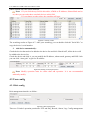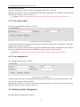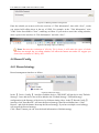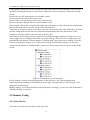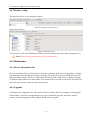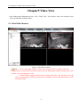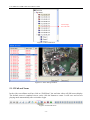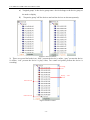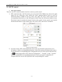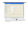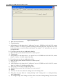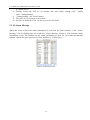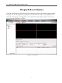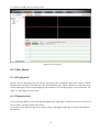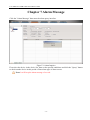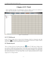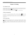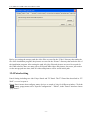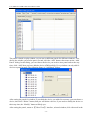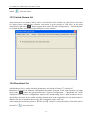
1
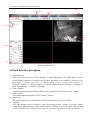
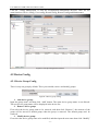
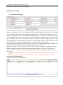
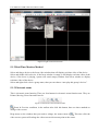
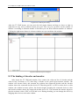
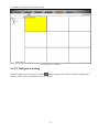
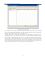
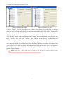
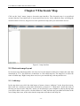
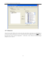
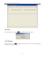
CMS Video Surveillance Client
User Manual
V2.42
Statement
Thank you for purchasing our prodCMSts! If you have any questions or need, please contact the
customer department at any time.
This manual applies to CMS video surveillance client software.
There may be technical inaccuracies and typographical errors in the manual. ProdCMSts, updated in
real time, the contents of the manual will be updated from time to time without prior notice. The
updated content will be added in new version. If it is inconsistent with the prodCMSts, please be on
the prodCMSts basis.
If in doubt or dispute manual, please refer to the final interpretation of the company.
Note for user manual
Video surveillance client is powerful monitoring software, set multiple windows, multi-user, voice
intercom, multiple windows, multi-user, playback, TV Wall, Map, Forward Service Setting,
Multi-screen display control compatible with other extension prodCMSts, Single straight even device
monitoring system is an organic whole for the function sCMSh as.
Video surveillance system is aimed at connecting more than one different type or model of equipment
(sCMSh as IPC, NVS, DVR, etc.), this manual only for professional network video surveillance
system of the client software operation are described, relate to a specific device feature setting, please
read the prodCMSt manual.
This manual is for the use of video surveillance system provided by the user. You should have the
relevant equipment (sCMSh as IPC, NVS, DVR, etc.) of the basic operational knowledge and
experience.
CONTENTS
CHAPTER1 FEATURES.................................................................................................................................................- 1 1.1 Main Features ......................................................................................................................................................- 1 CHAPTER2 OPERATING ENVIRONMENT REQUIREMENTS.............................................................................- 3 2.1 Hardware environment .........................................................................................................................................- 3 2.2 Software Environment ..........................................................................................................................................- 3 CHAPTER3 INSTALL AND UNINSTALL....................................................................................................................- 4 3.1 Installation Steps ..................................................................................................................................................- 4 3.2 Uninstall Steps......................................................................................................................................................- 7 CHAPTER4 CONFIG MANAGEMENT .......................................................................................................................- 8 4.1Main Interface description ....................................................................................................................................- 9 4.2 Device Config ..................................................................................................................................................... - 11 4.2.1 Device Group Config...................................................................................................................................................... - 11 4.2.2 Device Config .................................................................................................................................................................- 12 -
4.3 User config ......................................................................................................................................................... - 13 4.3.1 Role config......................................................................................................................................................................- 13 4.3.2 User group config ...........................................................................................................................................................- 14 4.3.3 User management............................................................................................................................................................- 14 4.3.4 Rolling Subtitles Management........................................................................................................................................- 14 -
4.4 Record Config..................................................................................................................................................... - 15 4.4.1 Record strategy ...............................................................................................................................................................- 15 4.4.2 Strategy config ................................................................................................................................................................- 16 -
4.5 Remote Config .................................................................................................................................................... - 17 4.5.1 Select device ...................................................................................................................................................................- 17 4.5.2 Remote config.................................................................................................................................................................- 18 -
4.6 Maintenance ....................................................................................................................................................... - 18 4.6.1 Device information list....................................................................................................................................................- 18 4.6.2 Upgrade...........................................................................................................................................................................- 18 4.6.3 Config file Upload and Download ..................................................................................................................................- 19 4.6.4 Reboot, Default Config and Sync system time ...............................................................................................................- 19 4.6.5 The management of front-end storage device .................................................................................................................- 19 -
CHAPTER5 VIDEO VIEW........................................................................................................................................... - 21 5.1.1 Real-Time Monitor .........................................................................................................................................................- 21 5.1.2 Real-Time Monitor Method ............................................................................................................................................- 22 5.1.3 Electronic zoom ..............................................................................................................................................................- 22 5.1.4 Dual-stream Switching....................................................................................................................................................- 23 5.1.5 Capture............................................................................................................................................................................- 23 5.1.6 Voice Talk .......................................................................................................................................................................- 24 5.1.7 Audio Switch...................................................................................................................................................................- 24 5.1.8 Broadcast Audio..............................................................................................................................................................- 24 5.1.9 Start to select the fragment of device record ...................................................................................................................- 24 -
5.1.10 Patrol.............................................................................................................................................................................- 25 5.1.11 Alarm Linkage...............................................................................................................................................................- 25 5.1.12 Full and Norm ...............................................................................................................................................................- 26 5.1.13 Screen Lock and Unlock ...............................................................................................................................................- 27 5.1.14 Stop Video.....................................................................................................................................................................- 27 5.1.15 Start all record...............................................................................................................................................................- 27 5.1.16 Full-screen Control .......................................................................................................................................................- 27 5.1.17 Device List....................................................................................................................................................................- 27 5.1.18 PTZ control ...................................................................................................................................................................- 29 5.1.19 Alarm Message..............................................................................................................................................................- 32 -
CHAPTER6 RECORD QUERY ................................................................................................................................... - 33 6.1 Video Query ........................................................................................................................................................ - 34 6.1.1 File playback...................................................................................................................................................................- 34 6.1.2 Time playback.................................................................................................................................................................- 34 -
6.2 Play back ............................................................................................................................................................ - 35 6.2.1 Local Record Playback ...................................................................................................................................................- 35 6.2.2 Front-end Record Playback.............................................................................................................................................- 35 -
6.3 Download Record ............................................................................................................................................... - 35 CHAPTER 7 ALARM MESSAGE................................................................................................................................ - 36 CHAPTER 8 TV WALL................................................................................................................................................. - 37 8.1 TV WALL LAYOUT ................................................................................................................................................... - 37 8.2 MONITOR LAYOUT ................................................................................................................................................... - 37 8.3 THE BINDING OF DECODER AND MONITOR ................................................................................................................ - 38 8.4 TV WALL PATROL SETTING....................................................................................................................................... - 39 CHAPTER 9 ELECTRONIC MAP .............................................................................................................................. - 42 9.1 ELECTRONIC MAP LAYOUT ....................................................................................................................................... - 42 9.1.1 Add map..........................................................................................................................................................................- 42 9.1.2 Add Sub Map ..................................................................................................................................................................- 43 9.1.3 Add Devices....................................................................................................................................................................- 43 -
9.2 PLAY DEVICES VIDEO ............................................................................................................................................... - 44 9.2.1 Real-Time Monitor .........................................................................................................................................................- 44 9.2.2 Full screen/exit full play .................................................................................................................................................- 45 9.2.3 Devices video change .....................................................................................................................................................- 45 9.2.4 Stop Video.......................................................................................................................................................................- 45 -
9.3 THE DELETE OF MAP AND DEVICE ............................................................................................................................ - 45 9.3.1 The delete of map............................................................................................................................................................- 45 9.3.2 The delete of device ........................................................................................................................................................- 45 -
9.4 THE PROPERTY OF MAP AND DEVICE......................................................................................................................... - 46 9.4.1 Map property...................................................................................................................................................................- 46 9.4.2 Devices Property.............................................................................................................................................................- 46 -
9.5 JUMP AMONG MAPS .................................................................................................................................................. - 46 CHAPTER 10 FORWARDING SERVICE SETTING................................................................................................ - 47 -
10.1 FORWARDING SERVICE SETTING ............................................................................................................................. - 47 10.2 REMOTE CLIENT RECEIVING AND DELIVERING CONFIGURATION ............................................................................. - 47 CHAPTER 11 MULTI-SCREEN DISPLAY ................................................................................................................ - 49 MULTI-SCREEN DISPLAY ................................................................................................................................................ - 49 CHAPTER 12 SETTING ............................................................................................................................................... - 50 12.1 Automatic Login ............................................................................................................................................... - 50 12.2 Boot Automatically ........................................................................................................................................... - 50 12.3 Storage Setting.................................................................................................................................................. - 50 12.4 Patrol setting .................................................................................................................................................... - 51 12.5 Switch Stream Set ............................................................................................................................................. - 53 12.6 Broadcast Set.................................................................................................................................................... - 53 12.7 Alarm Set .......................................................................................................................................................... - 54 12.8 About ................................................................................................................................................................ - 55 12.9 CMS Help ......................................................................................................................................................... - 55 -
User Manual of CMS Video Surveillance Client
Chapter1 Features
1.1 Main Features
¾
¾
¾
¾
¾
¾
¾
¾
¾
¾
¾
¾
¾
¾
¾
¾
¾
¾
¾
¾
¾
¾
¾
¾
¾
¾
¾
¾
¾
¾
¾
¾
¾
¾
¾
Support electronic zoom function
Support searching devices.
Support different permission of the users display different interface.
Support displaying the front-end device list.
Display online devices and offline devices by group.
Support maintaining and managing on-line status of front-end device.
Support multi-screen video window and full screen controls.
Real-time video streams to monitor.
Support clicking device group name then play this group’s devices automatic.
Support player window patrol
Support selected device video record.
Support playing window changes position
Support the client screen lock
Support video window display some playing status
Support TV Wall function.
Support the patrol of TV Wall
Support the decoder window shows decoder and encoder.
Support electronic map function.
Support multi-screen display function, up to support four screens.
Support PTZ control.
Voice talk.
Support broadcast audio.
Support distal device forward service setting.
Support PTZ protocol.
Support the window when sub stream switching main stream.
Support picture capture.
Support local record by the client.
Support local record four-screen sync playback.
Support device (local device, distal device) record (including local, distal) query and playback
as well as front-end record download.
Support displaying real-time alarm information of devices.
Support prodCMSe alarm when he played the alarm sound.
Support querying the historical alarm information.
Support real-time video surveillance of the window and the corresponding voice switch control
the display and maintenance of the status.
Support the record status of the video window display and maintenance.
Support the restoration of status control and management last time monitoring.
-1-
User Manual of CMS Video Surveillance Client
¾ Support YUV formats accelerated graphics (if you only use the card does not support YUV
RGB display).
-2-
User Manual of CMS Video Surveillance Client
Chapter2 Operating Environment Requirements
2.1 Hardware environment
Central Processing Unit (CPU): Intel Pentium Dual Core 2.0G or above.
Main Memory: DDRIII 2G or above.
NIC: 100/1000M adaptive.
HDD: 250G or above.
Graphics: GeForce4 256MB or above.
Display: 17 inch (or above) color LCD or CRT monitor, 1024 × 768 resolution (or above).
Note: If more real-time video and records, and to achieve better results, CPU, memory,
graphics must be configured higher.
2.2 Software Environment
Install CMS SOFT video surveillance client (called CMS for short), which support Windows
2000/XP/2003/7 operating systems, it is recommended not to use the following operating systems
Windows 98. Suggest Internet Explorer 6.0~9.0.
-3-
User Manual of CMS Video Surveillance Client
Chapter3 Install and Uninstall
3.1 Installation Steps
Double click”CMS SOFT_*.*_YYMMDD_***_setup.exe”, if your operating system language is
English, then it will come out an interface as Figure3-1. According to different need, the software
has four versions: English, Simplified Chinese, Traditional Chinese and Russian. Which version you
can install determined by your operation system language. In English system, you can only install
English version. The detailed step as follows:
Figure3-1
Step 1: Select the language "English", the Welcome wizard interface, as shown in Figure (3-2)
below;
Figure3-2
Step 2: Click "Next", select the installation directory, as shown in Figure (3-3) below;
-4-
User Manual of CMS Video Surveillance Client
Figure3-3
Step3: Click "Install", the installation is complete appears in Figure (3-4) below;
Figure3-4
Step4: Click “Finish” then the installation is finished. The function of “Run CMS SOFT” is that the
CMS SOFT searches all devices that your computer can connect to; if the device is not in the same
network of your computer then its IP will be modified; add all searched devices automatically; after
finished the auto-configure, when you login CMS SOFT in the first time, CMS SOFT will play front
nine devices automatically. When finished the installation of CMS SOFT, this function is enabled
by default, remove the hook before “Run CMS SOFT” then you will disable this function.
-5-
User Manual of CMS Video Surveillance Client
Figure 3-5
Figure 3-6
Figure 3-7
Figure 3-8
-6-
User Manual of CMS Video Surveillance Client
3.2 Uninstall Steps
Enter start menu "Programs”→”CMS”→“Uninstall", operation as follows:
Step 1: Click the "Uninstall" appears to lift interface, as shown in Figure (3-9) below;
Figure3-9
Step 2: Click the "Uninstall" Uninstall completed, as shown in Figure (3-10) below;
Figure3-10
Step 3: Click "OK" Uninstall completed.
-7-
User Manual of CMS Video Surveillance Client
Chapter4 Config Management
On the desktop, double click CMS (
) to start CMS login interface. As follow:
Figure4-1 Login Interface
The default username is admin, password is 123456. You can add user after login, the detail
operation will describe later. Check "Automatic login", CMS will save password and it will login
automatically. Check “Save Password” the CMS will save the password if you login sCMScessfully
this time, then you won’t need to enter its password next if you login with this username. In order to
ensure the security of the software, if the user checked the "save the password", then in CMS exit
after login, password a column shows the 32-bit key. CMS autosave recently login five user's letter.
-8-
User Manual of CMS Video Surveillance Client
Setting
Main Menu
Tool Bar
Device List
Video
window
Area
PTZ Control
Alarm
Figure4-2 Main Interface
4.1Main Interface description
1) Function menu:
Video View, Record Query, Alarm Message, Config Management, TV Wall, Map, Forward
Service Setting, Multi-screen display and Set main functional areas, detailed in Chapter4 Config
Management >>; Chapter5 Video View >>; Chapter6 Record Query >>; Chapter7 Alarm Message >>;
Chapter8 TV Wall >>; Chapter 9 Map >>; Chapter 10 Forward Service Setting >>; Chapter 11
Multi-screen display >>; Chapter 12 Setting;
2) Video Window:
According to the operation of the toolbar in above, details in “Real-Time monitor” section.
3) PTZ Control:
PTZ control operation details in “PTZ Control” section
4) Device list:
The region display device information, device list details in “Device list” section.
5) Tool Bar:
The video window can do electronic zoom, Dual-stream switch, Capture, Voice talk, Audio,
Broadcast, Manual Record, Patrol, Alarm action, Full/Norm, lock screen, Stop, Stop all, start
all record, full screen, single screen, 4 screens, 6 screens, 8 screens, 9 screens, 10 screens , 13
-9-
User Manual of CMS Video Surveillance Client
screens ,16 screens, 25 screens and 36 screens, 49 screens, 64 screens.
6) Setting:
You can set the software automatic login, boot automatically, system configuration, detailed in
Chapter 12.
A comprehensive introdCMStion to the various functions as follow (minimum resolution 1024 *
768).
- 10 -
User Manual of CMS Video Surveillance Client
Click the “Config Management” to enter the configuration management interface. There are five
main functions: Device config, User config, Record config, Remote config and Maintenance.
Figure4-3 Config management interface
4.2 Device Config
4.2.1 Device Group Config
There is only one group by default. There you can add, remove and modify groups.
Figure4-4 Device group config
1. Add device group:
Input the group name, and then click “Add” button. The same device group name is not allowed.
The new device group name will be displayed in the device list.
2. Remove device group:
First select the device group name to be removed, and then click “Remove”; the cameras of the
group will be moved to default group when the group is removed. The default group can’t be
removed.
3. Modify device group:
First select the device group name to be modified, and then input the new name then click “Modify”
- 11 -
User Manual of CMS Video Surveillance Client
button; the same group name is not allowed.
4.2.2 Device Config
1.
Add device manually:
Figure4-5 Device config
First select group name as figure4-5 and device type, input device name, protocol type<accessing
Internet recommended TCP>, device type<IPC, DVS, Decoder, Video Switch Server/VSS>, stream,
access method(The default access method of adding devices is RTSP, you can change the device’s
access mode<RTSP or TPS>. The standard method is RTSP; the TPS method is only for the device
can’t login IPSAN platform),device address<it can be IP address or domain name>, video port, PTZ
port (IP address, PTZ port and video port must be the same with IPC itself).Login name and
password must be the management of the device username and password, PTZ address code and
control PTZ address must be the same, otherwise the device will not work properly.
After setting those parameters click the button of “Add”, then you have finished manual-adding new
device. Modify and remove device are the same with add device, not repeat.
When Device Type "Video Switch Server/VSS", Device IP for distal open forwarding service host
address, and at the same time, also can be the main domain address, "Video Port" for the open
service set up the video port. Click on the "add" button, the server device will be added to the left
device list.
Note: Add distal device, if it is used to IP address form add will automatic filter out with
the same device, if it is used to do main name form will not add to the same device filter.
Search devices automatically:
CMS can search devices automatically.
Figure4-6 Search Camera
Click “Search Camera”.CMS will search all devices in the same LAN and will display all devices;
- 12 -
User Manual of CMS Video Surveillance Client
public network can’t use search function.
Note: 1. If you click the top field in this table, sCMSh as IP Address, Subnet Mask and so
on, then you can order those searched devices as this field.
2. If you change to other place, the searching will stop.
Figure4-7 Search camera
The searching results as Figure 4-7. After your searching, you can double click the” Serial NO.” to
copy the device’s serial number.
2.
Add device automatically:
Check the device that need to be added to the device list and click “Batch Add”, all the device will
be added to the device list.
Check the device and click it, you can modify the IP address, subnet mask, gateway and DNS. Oslo
you can click “Auto gain” to get free IP address.
Figure4-8 Modify network parameters
Note: Modify operation must be earlier than add operation. It is not recommended
arbitrarily modify.
4.3 User config
4.3.1 Role config
Role management interface as follow:
Figure4-9 Role management
There are 5 kind of operation permission: PTZ and Play, Record, Alarm, Log, Config management
- 13 -
User Manual of CMS Video Surveillance Client
and advanced operation.
Add role: Input the role name and check permissions then click “Add role”.
Modify role first select role to be modified then the similar with add a role. Select the role in the role
list then click “Remove role” to remove it.
Note: All the user groups and users of the role will be removed when remove the role.
4.3.2 User group config
User group management interface as follow:
Figure4-10 User group management
Add user group: Input user group name and select the group role then click “Add group”. The same
group users are the same user role.
Modify user group first select the user group to be modified then similar with add user group. Select
the user group in the user list and click “Remove group” to remove the user group.
Note: The user of the user group will be removed when remove the user group.
4.3.3 User management
User management interface as follow:
Figure4-11 User management
Add user: Input username, new password, confirm password and select user group then click “Add
user”. Do not allow the same username.
Modify user: Select a user in the user list then similar with add a user. Select the user in the user list
and click “Remove user” to remove the user.
4.3.4 Rolling Subtitles Management
Rolling subtitles management as follow:
- 14 -
User Manual of CMS Video Surveillance Client
Figure4-12 Rolling subtitles management
Enter the subtitle you want to roll in the text-box of “Title Information”, then click “Save”, words
you entered will rolling show in the top of CMS. For example, in the “Title Information” write
“CMS Video Surveillance Client”, rendering as follow. If you need to cancel the rolling subtitles,
enter a space in the text-box of “Title Information” and click “Save”.
Figure4-13 Rolling captions rendering
Note: Because the resolution of 1024 by 768 is lower, it will make the space of whole
interface not enough, the set rolling subtitles will affect the button area under. So suggest you
choose the resolution of 1280 by 960.
4.4 Record Config
4.4.1 Record strategy
Record management interface as follow:
Figure4-14 Record config
In the 【 Device Config 】 interface to add the device, CMS SOFT will put device into "Default
Strategy". Later add device also will be added to the "Default Strategy"."Default Strategy"
configuration is the Strategy of the device for 24 hours timing video. In the【 Record Config 】
interface click "Start Record", will start the Record strategy. Start Record button into a "Stop
Record", and click the button, then stop the Record strategy. If you have multiple record strategy,
will stop all the Record strategy.
Click “Detail” button you can view the detail information of default strategy.
- 15 -
User Manual of CMS Video Surveillance Client
4.4.2 Strategy config
Click “Detail” then enter the interface of record strategy detail configuration. As figure 4-15:
Figure 4-15 Record parameter configure interface
The configuration of record strategy includes two sides: Basic Config and Record Config. Next we
will have a detailed explain for every parameter.
Strategy name: There is a system default named Default Strategy, which can not modify. When you
need add other strategy, you can named by yourself but Default Strategy.
Storage Strategy: You have two choices, Stop record when full or Overwrite latest files when full.
Trigger method: Schedule Record refers to record all the time during the time you have set; Motion
detect Record refers to when has motion alarm then record, the premise is that the device has
already opened motion alarm; IO alarm record refers to when has IO alarm then record, the
premise is that the device has already opened IO alarm
Strategy path: The system will auto gain three disks as strategy, except your system disk. When user
need modify the strategy path can click the button of “Browse” to select path free. When user need
delete the strategy path,, click “Browse”, then click “Cancel” on the pop-up dialog box.
Original devices: All devices that you have added.
Strategy Devices: Devices in current record strategy. Modify record device you can by those buttons
between “Original devices” and “Strategy devices”
- 16 -
User Manual of CMS Video Surveillance Client
Config enable: When user choose yes and save, then open current record. Strategy record can also
opened by clicking the button of “start record”. When user choose no and save, then close current
record.
Record time per file: Record time for a schedule record.
Prerecord time: The time before start record.
Record video: User can choose sub stream or main stream.
Detect record time: Record time for a motion detect record.
Record audio: If hope the record file with audio you need choose it. Only when device encode audio
and checked it then the record file will be video and audio file.
Time slot set: It refers to set the record time, you can set seven time slots total. When there be some
conflict during different time slot, the system will automatically take there intersection. After
starting record, there will be video file only in the time slot.
Add strategy: When different device needs record in different trigger method, or when devices are
many, suggest you to configure more than one record strategy. Choose devices, configure the store
path and other parameters, click the button of “Add Strategy” then create a new strategy. There are
four record strategies in figure 4-16. If the record strategy is not default strategy, you can only
enable it by the button of “Config Enable”, choose yes means start record, choose no means finish
record.
Figure 4-16 Added four record strategies
Delete strategy: click the record strategy name on the left device list, related configuration
information for this strategy will detail show on the right. Click the button of “Del strategy” will
delete this record strategy.
Modify strategy: If you have modified some parameters for strategy, you need to click the button of
“Modify strategy” to ensure it
4.5 Remote Config
4.5.1 Select device
Click the device that must be online in the device list.
- 17 -
User Manual of CMS Video Surveillance Client
4.5.2 Remote config
The interface device is not selected as follow:
Figure4-17 Remote config interface
After select a device:
Figure4-18 Remote config
You can refer to IPC instrCMStions to modify network setup, media setup, alarm setup and so on.
Note: Remote config is not allows for DVS and decoder.
4.6 Maintenance
4.6.1 Device information list
Device information list is to check devices do below operating. Before device upgrading, configure
file uploading or downloading, rebooting, restoring, you must check devices first then you can do
those operating to them. The device information list only include online devices, during operating
(sCMSh as reboot) the device must offline for a moment, then you will see the device out of the list
and come out in the top of the list some minutes later.
4.6.2 Upgrade
Checked need to upgrade device, click on the "browse" button, the local computer to find upgrade
file the folder, select the corresponding device types of firmware program, and click "update",
namely start remote upgrade. If the upgrade failed, please try again.
- 18 -
User Manual of CMS Video Surveillance Client
Figure4-19 Upgrade
4.6.3 Config file Upload and Download
Upload config file: first click “Browse” to select the correct config file and check the devices to be
uploaded, then click “Upload”.
Download config file: first click “Browse” to select directory for saving cinfig file and check device
that download config file from, then click “Download”.
Figure4-20 Config file Upload and Download
4.6.4 Reboot, Default Config and Sync system time
Check devices and click “Reboot” to reboot the devices.
Check devices and click “Default Config” to restored the devices.
Check devices and click “Sync system time” to modify devices time.
Figure4-21 reboot, default config and sync system time
4.6.5 The management of front-end storage device
After choosing the device, click “Format”, then the TF card or USB device will be formatted.
After choosing the device, click “Uninstall”, then the TF card or USB device will be uninstalled.
- 19 -
User Manual of CMS Video Surveillance Client
Figure4-22 The management of front-end storage device
- 20 -
User Manual of CMS Video Surveillance Client
Chapter5 Video View
After adding and configuring devices, click “Video View”, then skip to video view interface, here
you can watch the real-time video.
5.1.1 Real-Time Monitor
Figure5-1 Surveillance interface
Note: 1. Two or more play window is when view playing, Select a window and click
continued one second, until a red camera sign come out, then drag to another window, those two
windows will exchange their video.
2. Video window supports the function of right-click mouse, The function of it is the
same as the function of buttons in the video surveillance tool bar, detail operation will be
described follow.
- 21 -
User Manual of CMS Video Surveillance Client
Figure5-2 right-click menu function
5.1.2 Real-Time Monitor Method
Select and drag a device to the focus video window that will display real-time video of the device.
Select and double click a device, if the focus window is empty, it will display real-time video of the
device; if the focus is playing, system will search empty window from focus window to display
real-time video of the device.
Select and right-click a device group name, then you can choose “auto play this group’s devices”.
5.1.3 Electronic zoom
This is electronic zoom function. There are four buttons in electronic zoom function area. They are
Pointer, Moving, Zoom Out and Zoom In.
Figure 5-3 Electronic zoom function button
Zoom In: Preview condition, in the toolbar after click this button, there are three methods to
enlarge video screen:
Drag mouse to the window that you need to enlarge, the mouse turns to
. This time click the
video screen, system will enlarge the video screen with current point as the center.
- 22 -
User Manual of CMS Video Surveillance Client
Drag mouse to the window that you need to enlarge, up roll the mouse wheel, current video screen
will enlarge show.
Drag mouse to the window that you need to enlarge, click somewhere then drag mouse without
releasing it. Then come out a red box, release the mouse as you need, video screen enlarge show.
Zoom Out: After the video screen enlarged, click this button and drag mouse to enlarged
window, then mouse turns to
. This time click mouse, video screen narrow show. You can down
roll the mouse wheel to narrow the video screen too.
Moving: After the video screen enlarged, click this button and drag mouse to enlarged window,
then mouse turns to
. This time drag mouse you can drag the enlarged video screen.
Pointer: After the video screen enlarged, click this button, the video screen will regain normal
size to show. If there are many devices enlarged, click it will regain all.
5.1.4 Dual-stream Switching
Due to network bandwidth limitations and the requirements of high-definition video, IPC and other
front-end device using dual-stream technology which can encode two completely different bit
stream (including a different resolution, frame rate, quality) at the same time. Main Stream used for
local real-time storage, Sub stream used for remote network transmission. Thus take into account
the image of high quality local storage requirements and long-range low-bandwidth network
transmission of images fluency requirements, to break through network bottlenecks and maintain
Endowment effect of the local HD storage.
In the video surveillance tool bar, click "V1/V2" button on the focus of the video window to switch
the video stream. If need to screen amplification not automatic switching main-stream, then see
Chapter12.5 Switch Stream Setting.
Figure5-4 Dual-stream switch
5.1.5 Capture
In the video surveillance tool bar, click on “Capture” button on the focus of the video capture video
window. The default storage path of local record is in the “Picture” directory that under the file of
the installation program, if you want to change the storage path please turn to Chapter12.3 Storage
setting.
Figure5-5 Capture
- 23 -
User Manual of CMS Video Surveillance Client
5.1.6 Voice Talk
In the video surveillance tool bar, click on the “Voice talk” button in the video window with the
focus on real-time front-end device features two-way voice talk. When the voice talking is turned on,
the user switch the focus window will make no difference with it. And the status bar under the video
window will show current voice talk status.
Figure5-6 Voice talk
5.1.7 Audio Switch
In the video surveillance tool bar, click on the "Voice” button, you can open or close the focus of
the audio video stream monitoring. When the sound is turned on, the user can switch the focus to
follow the audio window to switch the focus of the window. And the status bar under the video
window will show current voice status.
Figure5-7 Audio
5.1.8 Broadcast Audio
Broadcast Audio realization must first configuration broadcast audio encoding format and need to
broadcast device, the specific configuration method and process see Chapter12.6 Boradcast Set.
For device set up after the broadcast, in the video toolbar and click
button, the button into
,
device into the broadcast state. If you want to stop broadcast again, click on the "Broadcast Audio"
button.
Figure5-8 Broadcast Audio
5.1.9 Start to select the fragment of device record
In the video surveillance tool bar, click the “Start to select the fragment of device record” button, the
focus of the video window will start record. The same time the button changes from
. Button
to
always represent that the device is recording, and if you want to stop record
please click the button
. Once manual record the longest time is 30 minutes, 30 minutes later
the system will cut down current record and start a new record. The default storage path of manual
- 24 -
User Manual of CMS Video Surveillance Client
record is in the “Video” directory that under the file of the installation program, if you want to
change the storage path please turn to Chapter12.3 Storage setting.
Figure5-9 Start to select the fragment of device record
5.1.10 Patrol
Start patrol you must configure patrol for video window first, the detailed configure method and
process will be explained in Chapter12.4 Patrol Setting.
After configured patrol for window, select the window and click the button
surveillance tool bar, then button turns to
in the video
, the window is patrolling. During patrolling the button
of “dual-stream switch”; “local record”; “voice talk”; “voice” can’t use. If want to stop patrolling
re-click the “patrol” button, then this window will play the real-time video streaming of the
stop-time device. This moment that four buttons can’t use still.
Figure5-10 Patrol
5.1.11 Alarm Linkage
Alarm linkage: enable it. When CMS receives alarm, it wills response to the alarm in different ways.
Three methods of alarm linkage: No1. Tree node flash (as figure 5-12).No2.Play alarm sounds.
Different sounds of master device and camera.No3.pop video window and play video. If there are
many devices alarming, it will play video of the first alarm. In the alarm list (as figure 5-13).Red
alarm information means the alarm not processed, black alarm information means the alarm already
processed. Click the “Begin speak” button, voice talk is opened.
Figure5-11 Alarm linkage
- 25 -
User Manual of CMS Video Surveillance Client
Alarm linkage
Tree node flash
Figure5-12 Tree node flash
Figure5-13 Alarm linkage window
5.1.12 Full and Norm
In the video surveillance tool bar, click on “Full/Norm”, the real-time video will full-screen display.
The default screen is standard screen; twice click the button to return. It will save and recover
playing mode automatically after exit and re-login.
Figure5-14 Full and Norm
- 26 -
User Manual of CMS Video Surveillance Client
5.1.13 Screen Lock and Unlock
In the video surveillance tool bar, click the "lock screen” button, then all CMS operating screen will
be locked. This moment, you can do nothing but watch the video streaming. And the button appears
to
if you want to exit this status, click it. Then an input-box pops and you must input your
username and password to sCMScess unlock.
Figure5-15 Lock screen
5.1.14 Stop Video
In the video surveillance tool bar, click "Stop" button to stop the current the real-time stream of the
focus window. Click "Stop all" button to stop all real-time video.
Figure5-16 Stop video
5.1.15 Start all record
Enter the interface of [Config Management] – [Record Config], right configured the record strategy
you need. Then return to the interface of [Video View], click the button of “Start all records”, all
records strategy will be opened. This button is a shortcut button for strategy record.
Figure5-17 Start all records
5.1.16 Full-screen Control
In the video surveillance tool bar, click on the corresponding split-screen button to switch to a
different monitor screen, 1 screen, 4 screens, 6 screens, 8 screens, 9 screens, 16 screens, 25 screens,
36 screens, 49 screens, 64 screens. Click on "Full screen" button will present a single screen or
multi-screen to full screen. Click "Esc" button to exit full-screen
Figure5-18 Full screen
5.1.17 Device List
1) There are two ways the device list display: “Original” group(Figure 5-19 left) and "Properties"
group (Figure 5-19 right):
- 27 -
User Manual of CMS Video Surveillance Client
a) "Original group" is the device group name +device belongs to the device group as
the node to display
b)
"Properties group" off-line devices and on-line devices are shown separately.
Figure5-19 Device list tree
2) There are several leaf node icon, “blue” present the device is online, “gray” present the device
is offline, “red” present the device is play video; Two small red points present the device is
recording.
Recording
devices
Playing
devices
Online devices
Offline devices
Figure5-20 Device status
- 28 -
video
User Manual of CMS Video Surveillance Client
5.1.18 PTZ control
1.
PTZ control method
There are two PTZ control methods: Interface control, joystick control.
1) PTZ control interface: In PTZ control, you can operate PTZ sCMSh an up, down, left, right,
adjust the iris, adjust the focus, adjust the zoom, add/query/delete preset as well as
advanced features sCMSh as call; up, down, left, right, iris, focus, zoom control in the
corresponding function key on the left began to hold, release the left mouse button to stop.
Directional control can adjust horizontal velocity and vertical velocity control; preset point
and advanced features of the control rules refer to the “PTZ control rule” document.
Figure5-21 PTZ control
2) Joystick Control: PTZ control keyboard access to the specified PC keyboard for use in
accordance with the corresponding parameters. client-side under the keyboard also need to
set the parameters corresponding to the configuration, the user clicks on the main interface
of
buttons popup menu select "System Configuration" – “Joystick”, In the " Joystick"
interface configuration corresponding parameters can be preserved. Configuration is
completed the user can use the keyboard to the corresponding PTZ control.
- 29 -
User Manual of CMS Video Surveillance Client
Figure5-22 PTZ joystick control
3) PTZ Protocol Control: Control of if PTZ device support custom PTZ control protocol
control, the user clicks on the main interface of
buttons popup menu select "System
Configuration" – “PTZ”, in the “PTZ” interface select PTZ protocol , after the completion
of the user configuration can be used in the preview interface PTZ control panel for the
corresponding PTZ control.
- 30 -
User Manual of CMS Video Surveillance Client
Figure5-23 PTZ Protocol
2. PTZ advanced function
1) Timing homing:
a. Add parameter in the input box of “add preset” to set it. SCMSh as 1#01:00-01:59, means
from 1 o’clock to 2 o’clock, if you had set timing scan during this time, then the device will
back to the preset every five minutes and stay for one minute. “1#” means first one, you can
set eight in total.
b. Every day you can only set eight timing homing.
c. Show the time period, and it will show in “remove preset”.
2) Timing orbit
a. Add parameter in the input box of “set preset” to set it. SCMSh as s1#01:00-01:59, means
from 1 o’clock to 2 o’clock orbit all the time.
b. Every day you can only set eight timing orbits.
c. Show the time period, and it will show in “remove preset”.
3) Timing scan
a) Add parameter in the input box of “add preset” to set it. SCMSh as o1#01:00-01:59, means
from 1 o’clock to 2 o’clock scan all the time.
b) Every day you can only set eight timing scans.
c) Show the time period, and it will show in “remove preset”.
4) Notice:
a) The time can not cross between “timing scan” and ”timing orbit”.
b) The time can cross between “timing homing” and ”timing scan” or “timing homing”
and ”timing orbit”.
c) If “timing homing” and ”timing scan” have time cross then “timing homing” first. the same
- 31 -
User Manual of CMS Video Surveillance Client
as “timing orbit”.
d) Nobody control the PTZ for six minutes later then begin “timing scan”, ”timing
orbit”, ”timing homing”.
e) “Timing homing” stay for one minute.
f) The value you set accurate to the minute.
g) Set time as o1#00:00-23:59, can not set as o1#23:59-00:00
5.1.19 Alarm Message
When the client receives the alarm information in real time the main interface of the "Alarm
Message" will be flashing, the user clicks the "Alarm Message" button to view real-time alarm
information screen. The interface for the alarm information to show the 16 records dynamically
updated. Alarms for query previous see instrCMStions of "Alarm Query ".
Figure5-24 Real-time alarm
- 32 -
User Manual of CMS Video Surveillance Client
Chapter6 Record Query
Click the "Record query" menu and go to the record query interface. Record query pages include
file playback and time playback. File playback include local record query, record playback and
front-end record query, record playback, record download, Time playback support local record
four-screen sync playback, as follow:
Figure6-1 File playback
- 33 -
User Manual of CMS Video Surveillance Client
Figure6-2 Time playback
6.1 Video Query
6.1.1 File playback
Select a device that queried in the device list and set the conditions, then click "Query" button.
Record source include "Local Record" and "Front-end Record". Select a different record sources are
not the same type of the corresponding record resolution. 20 records per page, you can click the “Pre
page” or "Next page" to view more.
6.1.2 Time playback
User in the time frame to select the desired inquires the video time, click on the device to the list of
device name, can show inquire the record.
Every time it can display seven device query results, click again on the query results will eliminate
the earliest.
- 34 -
User Manual of CMS Video Surveillance Client
6.2 Play back
6.2.1 Local Record Playback
Entering [Config Management]-[Record Config], configuring the record strategy and starting record,
in this way you can get local record. Local record files saved in local computer. In file playback
interface double click one of the searched video then it will play in playback window. You can
playback four records at the same time; In time playback interface double click the query result can
replay a equipment a video of the time, you can playback four-screen records at the same time. In
the playback window, your can operate the tool bar below to pause/play, frame forward, stop, fast
forward, previous section, next section, slow forward, taking picture, sound and so on. The default
storage path of taking picture is in the “Picture” directory that under the file of the installation
program, if you want to change the storage path please turn to Chanpter12.3 Storage setting.
Note: 1. If device is not video strategy, file playback can't search local video file, time
playback retrieval local video file for grey.
2. Fragment of device record files can't be retrieval.
3. During replaying video, you can use electronic zoom function too. The use
method of every button is the same as Video View, now we will not repeat again.
6.2.2 Front-end Record Playback
Front-end device with storage device, configured record strategy and started record, in this way you
can get front-end record. Double click one of the searched video then it will play in playback
window. One device can only play one video file in the same time. In the playback window, your
can operate the tool bar below to pause/play, frame forward, stop, fast forward, previous section,
next section, slow forward, taking picture, sound and so on. The default storage path of taking
picture is in the “Picture” directory that under the file of the installation program, if you want to
change the storage path please turn to Chapter12.3 Storage setting.
6.3 Download Record
Local record saved in your computer so you needn’t download it. The record download is front-end
record download. If you want to download the records, simply "Check" the record and then click the
"Download" button. Record of the default storage path is the default storage strategy path
“Remotion”. Users who want to stop downloading click the "Cancel" button.
Note: Download the video can not be other operations of the menu items.
- 35 -
User Manual of CMS Video Surveillance Client
Chapter 7 Alarm Message
Click the "Alarm Message" then enter the alarm query interface.
Figure7-1 Alarm Inquires
First select the device in the device list, then set the queried conditions and click the "Query" button
to check out the device in this period of time alarm type of alarm occurs.
Note: It will keep the alarm message of a week.
- 36 -
User Manual of CMS Video Surveillance Client
Chapter 8 TV Wall
Click “TV Wall” then skip to TV wall interface. Only the “admin” user has access authority, to
others CMS will prompt that “without TV Wall management permission”.
Figure 8-1 TV Wall interface
8.1 TV Wall layout
In the TV Wall interface, left is a device list, the function of this list is almost the same that
mentioned in 5.1.11, the difference is that this device list includes decoder device. Right is monitor
layout area, in this area you can overall layout for your monitor.
8.2 Monitor layout
There is a button in the top of monitor layout area,
named TV Wall layout, clicking it then
come out the TV Wall layout setting window. In this window you can set the number of Horizontal
lines and Vertical lines, the setting range from 1 to 20. After setting, clicking the “save” button then
the monitor layout area will layout as your setting. If you don’t set it will layout in default setting
that means horizontal line is ten and vertical line is ten too. When the decoder device is many,
suggest you to set a bigger number.
- 37 -
User Manual of CMS Video Surveillance Client
Figure8-2 TV Wall layout setting
After the TV Wall layout, you can press the left mouse button and drag to down or right or
right-down in any area of monitor layout area grid. This way you can draw out the window of
monitor. According to different number of decoders you can draw different number of windows.
Clicking the right mouse button in a drawn window area you can delete this window.
Figure8-3 Monitor layout Configure
8.3 The binding of decoder and monitor
After layout the TV Wall and monitor, first, connect the video-out line of decoder and the
video-in line of monitor or TV; then drag a decoder to the good layout monitor window. The
window will become black, this moment the software has connected decoder and the decoder
window shows the connected decoder device IP. Then drag an IPC or NVS or other device to this
window, the window becomes yellow, the decoder begins decoding the connected device’s video
and decoder window shows the connected encoder device IP . This moment the monitor begins to
play the real-time video of IPC or NVS and so on. During decoding you can change the device by
dragging other devices to decoder window.
- 38 -
User Manual of CMS Video Surveillance Client
Figure8-4 Decoder binding
8.4 TV Wall patrol setting
Decoder support device’s patrol. Click the
button, popup menu select "System Configuration" "Patrol", in the "Patrol" interface choose "TV Patrol".
- 39 -
User Manual of CMS Video Surveillance Client
Figure8-5 TV wall in turns setting
In “TV Patrol”, left is decoder list, CMS will display all decoder devices in this list by searching
from device list automatically. Right is the show area of patrol setting. There are four buttons in the
bottom of “Patrol setting”, “Add”; “Delete”; “Modify”; “Save”.
Clicking “Add”, come out “Add Patrol” dialog. There are two display choices “Display one video”
or “Display four video”; the “Stay Time” can’t less than 10s; click a device that in the left device list,
then it will show in the right column named “Device”. After that, click “Add” then you have added a
device for patrol sCMScessfully. By this way, you can add other devices. If you want to add four
video display, you need to click four devices, those devices will display in “Device” by the click
times. A decoder patrol you can add ten devices at most (a four video display is looks as one device).
After you added you must click the “Save” button then your setting is effective.
- 40 -
User Manual of CMS Video Surveillance Client
Figure8-6 Display one video
Figure8-7 Display four video
Clicking “Delete”, you can delete the device of patrol. First choose the decoder that you want to
delete its device, second choose the device that you want to delete, third click “Delete” button. After
you deleted you must click the “Save” button then your setting is effective.
Clicking “Modify”, you can modify the device of patrol. Choose the decoder, then choose the device,
click “Modify” button, come out “Modify Patrol” dialog. You can modify the screen display; stay
time or device. After that, click “Modify” then you exit modify dialog, but this time your
modification has no effect, only when you click the “Save” button then your setting is effective.
After you configuring device’s patrol, exit the “TV Patrol” dialog, draw a window in monitor layout
area, drag a decoder device to the window, click the “Patrol” button, the monitor will begin to play
patrol video. You can also start patrol when the monitor is playing real-time video. Click again the
“Patrol” button, you can end the patrol. After the patrol is ending, the decoder end decoding, the
monitor display nothing.
Note: Under the TV Wall, when there is one device the decoder decode main stream; when
there are more than one device the decoder decode sub stream.
- 41 -
User Manual of CMS Video Surveillance Client
Chapter 9 Electronic Map
Click on the "map" menu, jump to electronic map interface. The electronic map is a specialized
custom function, convenient user to layout and locate device. After added the map, according the
actual location of devices, drag devices to the position on map, then you can monitor devices.
Figure 9-1 map interface
9.1 Electronic map layout
In electronic map function module, left is device list, the function of this list is almost the same that
mentioned in 5.1.11, the difference is that there is a list called map-list. The map-list is to show the
name of added map. Right is map show area, here you can add map, sub map and devices.
9.1.1 Add map
In the map shows area click the right button of mouse, choose “add map” in the drop-down menu,
then come out a window to enter some information, as figure 9-2. “Map name” means the name of
the map you need to add. “Map file” means you need browser your computer to choose the map that
you need to add in. After you set, click the button of “Add” then the map you added will show in the
area of map-show-area, at the same time the map name will show in the map list.
- 42 -
User Manual of CMS Video Surveillance Client
Figure 9-2 Add Map
Figure 9-3 Map List
9.1.2 Add Sub Map
Sub map is the detail show for some area of map. When the map you added is very big and some
area are not detail, you can add a sub map in this area. The way to add sub map is similar to the way
to add map, the difference is that before you add sub map you need select the place to add it. Where
you select where will be a sub map. After you added sCMScess, there is an icon in the map, click it
then you can enter sub map.
Figure 9-4 Map List
Note: If you add no map, the option of "add sub map" is not available. A map can add more than one
sub map. The format of the map must be .jpg.
9.1.3 Add Devices
You can add device into map and sub map. Select the map, click “Original” or “Properties” in the
left device list, then select the device you need, drag it to the target position on map, after that
release the mouse, then you add device sCMScess. After added devices sCMScess, you will see an
icon and the device’s IP on map.
- 43 -
User Manual of CMS Video Surveillance Client
Figure 9-5 Devices Add SCMScess
Note: A device can not add for many times, but a map can add more devices.
9.2 Play devices video
9.2.1 Real-Time Monitor
When you need monitor a device, click the device icon on the map, then will come out a video play
window. Now you can by the right-mouse-function do some operation sCMSh as video play, stream
switch, voice talk, capture, manual record and so on.
Figure 9-6 Video window
- 44 -
User Manual of CMS Video Surveillance Client
Note: Video window supports the function of right-click-mouse. The function of it is the same as the
function of buttons in the video surveillance tool bar, we will not description again.
9.2.2 Full screen/exit full play
Double-click the video window, video will full display, double-click again, then exit full
display. When in full display, the function of right-mouse can also be used.
9.2.3 Devices video change
On the map, click the device icon you can open its video, this time click another device icon the
video will change, in this way you can choose to play your device video. Change map the video
window will not be closed.
9.2.4 Stop Video
You can stop the video by three methods:
1: Click the button
in the side of right-up for the video window, then video will stop and
window will be closed.
2: Click video window and click the right button of the mouse, choose “stop” in the pop-up box,
then video stop, but the window will not close.
3: Change the main interface from “Map” to other interface, video stop and window closed.
9.3 The delete of map and device
9.3.1 The delete of map
When the map has some changes or the map is too old, you need delete it. First, select the map you
need to delete. Second, click the right button of the mouse, come out a pop-up box. Third, click the
option of “delete map”. There will be two situations. If there is no device on the map, then delete the
map directly, and the device’s icon disappears; otherwise, there come out a notice window “The map
has device, are you sure to delete it?” click “OK” then delete all information for this map include its
device information and jump to its father map.
Note: if the deleted map has sub map, then when you delete it the sub map be deleted also. Think
of that there may be devices on the map, so we do not support the function of update map. When
the map has changes, you must delete it first and add the new version.
9.3.2 The delete of device
Find the device you need to delete, put the mouse on its icon, click right button, then choose the
option of “delete device”, by this way you can delete it and its all information.
- 45 -
User Manual of CMS Video Surveillance Client
9.4 The property of map and device
9.4.1 Map property
Choose the map, click right button of the mouse on it any where, then choose the option of
“Property”, after that come out a map property window, as figure 9-7.
Figure 9-7 Map Property
9.4.2 Devices Property
Choose the device, click right button of the mouse, choose the option of “Property”, after that come
out a device property window, as figure 9-8.
Figure 9-8 Devices Property
9.5 Jump among maps
There three methods jump among maps:
1. Switch back and forth: click the map name in “map list” which is on the left, then jump
to the corresponding map.
, click it, then jump to sub map.
2. Enter sub map: if there is an icon like
3. Back to the top: click right button of mouse on any where of sub map, choose the
option of “back”, the map jump to its father map.
- 46 -
User Manual of CMS Video Surveillance Client
Chapter 10 Forwarding service setting
10.1 Forwarding service setting
Forwarding service to the current CMS data server forwarding to distal CMS client. In the main
interface click on the top right corner
button, popup menu select "System Configuration" - "
Forward Service Setting". In "Forward Service Setting" interface CMS will automatically search to
the machine's IP address displayed in the local address bar, set “Local Port”, “Number of” and “User
Count”, checked after
, click the "ok" button forwarding service can take
effect. If you want to cancel the forwarding service is put out
check, in click
"ok" can stop forwarding service. If the "Number of" or "User Count" modified, simply click on
"modify" button effect.
Figure10-1 Forward Service Setting
Note: If you need to public network remote forward, it must be in the router to forward the local
mapping server IP address and port, public network remote client CMS with public network IP
address and mapping port receiving and delivering data.
10.2 Remote client receiving and delivering configuration
CMS remote client to receiving and delivering server data, must be in remote client "Config
Management" - "Device Config" page configuration add forwarding servers, as below:
- 47 -
User Manual of CMS Video Surveillance Client
Figure10-2 Add Forward Server
In the device type drop-down box select "Video Switch Server/VSS", input device name, select
protocol type, configuration device IP for forwarding the server address (if public network
forwarding, must complete and public network address), the video port forwarding servers for the
local port (if public network forwarding, must complete and mapping port), login name and
password for remote CMS client user name and password, click "Add" can add connection already
open forwarding service device to the left device list. As below:
Figure10-3 Forward Server Device List
Add forward server, other functions and operation with local client similar, one no longer give
uncecessary details
- 48 -
User Manual of CMS Video Surveillance Client
Chapter 11 Multi-screen display
Multi-screen display
Multi-display control is to point to in multiple display extended play streaming video, record query
and playback, alarm message, config management, TV wall, map function. These displays united by
a host control, maximum four screen display (sCMSh as digital matrix). The realization of screen
display need according to different needs in the host connection of multiple video card, each video
card at the same time the most connecting two table display. After connected monitor, login CMS,
the software will automatically recognize the number of monitor.
In addition to the main screen video preview interface outside, you can move any function into
extend monitor. In the main function on the menu than the current function menu select need to
move extended interface, click right button, then come out a pop-up box, as following figure, choose
the number of the extend monitor, then this interface move into the extend monitor. If the interface
has moved to extend monitor, click it in main monitor will have no function. The moved interface
you can operate it just the same as it in main monitor. When you need it come back to main monitor,
just click it on main monitor and right click mouse, click the selected extend monitor, then it come
back main interface. When your host just with a monitor, right click mouse will not come out the
following window.
Note: When in multi-screen environment, if you need to use PTZ function, the device video must be
played in main screen.
- 49 -
User Manual of CMS Video Surveillance Client
Chapter 12 Setting
12.1 Automatic Login
Automatic login premise is to save the user password, if want to open the CMS automatic login, in
the login interface "automatic login" check box to choose and will automatically checked save
" click "automatic login".
password, or in the main interface "
Cancel the automatic login again in the main interface "
" click "√automatic login".
12.2 Boot Automatically
If you want to run startup autorun login CMS, in the main interface "
" click "boot
automatically" can. Cancel the startup autorun is again in the main interface "
" click "√boot
automatically", but automatic login not cancelled, if want to cancel must click again on the tick "√
automatic login".
12.3 Storage Setting
Player Patrol means that configure many devices to round of play for different window. Click the
” button in the upper right corner of the main interface, popup menu select "System
“
Configuration" - "Storage", in the "Storage" interface click on the "browser" button, the user can
choose according to their own needs the local path, choose good after click "save" setting is
effective.
- 50 -
User Manual of CMS Video Surveillance Client
Before you setting the storage path, the video files are saved in the “Video” directory that under the
file of the installation program; the pictures are saved in the “Picture” directory that under the file of
the installation program. After setting the path, all video files and pictures are saved in set path. In
the CMS software, there are many places will prodCMSt videos and pictures, but a user just need to
set the storage path one time, then all videos and pictures will be saved in this path.
12.4 Patrol setting
Patrol Setting including two side: Player Patrol and TV Patrol. The TV Patrol has described in “TV
Wall”, we won’t repeat it.
Player Patrol means that configure many devices to round of play for different window. Click the
” button, popup menu select "System Configuration" - "Patrol", in the "Patrol" interface choose
“
"play Patrol".
- 51 -
User Manual of CMS Video Surveillance Client
The patrol is based on play window, so you can set different patrols for different windows. First,
choose the window you need to patrol; second, click the “Add” button; then come out the “Add
Patrol” dialog. In this dialog, you can choose the device you need to enter patrol and set the stay
time, click “Add” then you have added a device sCMScessfully. Every window can only add 10
devices to patrol at most. The following figure is “Add Patrol” dialog.
After setting the patrol for window, if you think the device you added is too many, you can choose a
device, then click “Delete” button, that you will delete a device; if you need to modify the device or
their stay time, the “Modify” button will help you.
After setting the patrol, return to 【Video View】 interface, selected window, click video tool in the
- 52 -
User Manual of CMS Video Surveillance Client
article "
" tour can wheel.
12.5 Switch Stream Set
Switch stream set can make CMS in video view interface video window by split-screen conversion
for single picture subcode flow whether conversion is given priority to code flow. In the main
interface top right click "
" button, popup menu select "System Configuration" - "Switch Stream",
in "Switch Stream" checked Settings dialog box can be effective
12.6 Broadcast Set
Add broadcast device, audio encoding format have two kinds of forms: G711 and AAC.
Broadcast set means for different configuration broadcast function. In the main interface top right
click on the "
" button, the popup menu select " System Configuration " - "Broadcast Set", in the
"Broadcast Set" interface configuration requires the broadcasting device. Add broadcast device,
should first check the device audio encoding format, then in the original device list checked device
added to the left of broadcast device list, after completion of the click "ok".
After setting the broadcast, return to 【Video View】 interface, selected window, click video tool in
the article "
" tour can wheel.
- 53 -
User Manual of CMS Video Surveillance Client
12.7 Alarm Set
Alarm Set can make CMS in device alarm when they make alarm sound and open alarm linkage is
" button,
sent from the alarm switch between voices. In the main interface top right click on the "
the popup menu select “System Configuration” - "Alarm Set", in the "Alarm Set" checked Settings
dialog box can be effective.
- 54 -
User Manual of CMS Video Surveillance Client
12.8 About
In the main interface, you can click "
" and "About" to view the CMS version.
12.9 CMS Help
In the main interface click "
", popup menu select" help" as well as in the start menu program
CMS directory can open" CMS help".
- 55 -