1
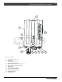
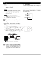
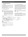
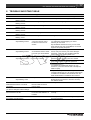
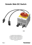
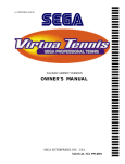
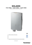
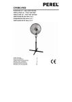
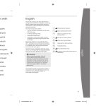
SOLADIN 700 WEB / 1000 WEB / 1500WEB GRID CONNECTED SOLAR INVERTER EN Other languages: USER’S AND INSTALLATION MANUAL See WWW.MASTERVOLTSOLAR.COM/SOLADINWEB 10000005892/05 compatible 2 EN / Soladin 700/1000/1500 0 Web User’ss Manual EN NGLISH Thiis manual servves as a guide eline for the sa afe and effectiive use and in nstallation of th he Soladin: For the installler this manua al instructs in the installation n, operation and a commissio oning. For the end u user, this manual instructs in n operation, in nverter mainte enance and po ossible correcttion of minor malfunctions. m Every person n who works with w the apparatus should b be familiar with the contentts of this mannual, and mus st carefully folllow the instructions contained herein. Store the ma anual in an acccessible place e. EDERLANDS NE Deze handleiding g dient als rich htlijn om de So oladin op een veilige en doe elmatige wijze e te installerenn en te gebruik ken: Voor de insta allateur geeft deze d handleiding aanwijzing gen voor het plaatsen, p bedie enen en in beddrijf stellen. Voor de gebruiker geeft deze d handleiding aanwijzing gen voor bediienen, onderh houden en hett zelf oplosse en van eventuele kleine storing gen. Iedereen die e aan of met het apparaat werkt, installa ateur en gebrruiker moet va an de inhoudd van deze ha andleiding op de hoogte zijn en de instructie es daarin nauw wgezet opvolg gen. Bewaar de handleiding op een goed toe egankelijke pla aats in de nabijheid van de Soladin. S DE EUTSCH Die ese Anleitung dient als Rich htlinie für die sichere und efffektive Installa ation und den Betrieb des Sooladin: Für den Elekktriker enthält diese d Anleitun ng Anweisunge en für die Installation, den Betrieb B und diee Inbetriebnah hme. Für den End dbenutzer enthält diese An nleitung Anwe eisungen für den d Betrieb, die d Wartung uund eine mög gliche Behebu ung kleinerer Feh hlfunktionen de es Soladin. Jede Person n, die mit dem m Gerät arbeitet, muss mitt dem Inhalt dieser d Anleitung vollständigg vertraut sein und die hie erin enthaltenen A Anweisungen sorgfältig befo olgen. g muss für den n Benutzer sofort zugänglicch sein. Die Anleitung RANÇAIS FR Ce manuel a été é conçu pour servir s de directtives à l’installlation sécurisé ée et effective du Soladin: des instructio ons d’installation, de fonctionnement et de e Mise en serv vice sont fourn nies à l’attentiion des électriciens. des instructio ons de fonctionnement, d’en ntretien et d’évventuelles corrrections de dy ysfonctionnem ments mineurs s du Soladin sont fournies à l’attention des utilisateurs. toute personne travaillant sur ou avec l’appareil doit a avoir une connaissance approfondie du ccontenu du prrésent manuel et doit suivre sccrupuleusement les instructiions ci-après. Conserver ce e manuel danss un endroit fa acilement acce essible à l’utilisateur. SPAÑOL ES Estte manual esta ablece las pau utas para la in nstalación efecctiva y segura del Soladin: Al electricista a este manual le sirve de gu uía para la insttalación, el funcionamiento y la puesta enn marcha. Al usuario final le ofrece instrucciones s para el funccionamiento, el mantenimie ento y la possible correcció ón de pequeñ ñas anomalías de el Soladin. Todas las pe ersonas que trabajen con el aparato d eben estar plenamente p familiarizadas ccon este man nual y seguir de manera minu uciosa las instrucciones con ntenidas en el mismo. n lugar de fácil acceso. Guarde este manual en un ITA ALIANO Il presente p manu uale funge da orientamento per un’installa azione ed un funzionamento f o sicuri ed effiicaci del Solad din: All’elettricista a, il presente manuale m dà de elle istruzioni p per l’installazio one, il funzionamento e la m messa in servizio. All’utente fin nale, il presen nte manuale dà delle istru uzioni per il funzionamentto, la manuteenzione ed eventualmente la soluzione di m malfunzionam menti di minore e entità del So oladin. Chiunque lavvori con quessto impianto deve d familiarizzzarsi del tutto o con il conte enuto del pressente manuale e seguire con c attenzione le istruzioni in esso e contenute e. eve essere immediatamente e accessibile a all’utente. Il manuale de EN / Soladin 700/1000/1500 Web User’s Manual 1 2 12 3 4 11 5 Figure 0-1: Overview 1. 2. 3. 4. 5. 6. 7. 8. 9. 10. 11. 12. Power LEDs (Section 6.4) Cooling fan WIFI LED (Section 6.4) Status LED (Section 6.4) AC connection compartment (Chapter 5) WIFI connection button (Section 6.4) WIFI antenna DC plus input (Chapter 5) DC minus input (Chapter 5) Ground screw (Chapter 5) Identification label Cooling outlet 6 7 8 9 10 3 4 EN / Soladin 700/1000/1500 Web User’s Manual TABLE OF CONTENTS: 1 GENERAL INFORMATION .............................................................................................................................................. 6 1.1 Product description ............................................................................................................................................. 6 1.2 Use of this manual .............................................................................................................................................. 6 1.3 Validity of this manual......................................................................................................................................... 6 1.4 Scope of warranty............................................................................................................................................... 6 1.5 Liability ............................................................................................................................................................... 6 1.6 Changes to the Soladin ...................................................................................................................................... 6 1.7 Identification label ............................................................................................................................................... 6 2 SAFETY GUIDELINES AND WARNINGS ....................................................................................................................... 7 2.1 Warnings and symbols ....................................................................................................................................... 7 2.2 Use for intended purpose ................................................................................................................................... 7 2.3 Installation, maintenance, repair ......................................................................................................................... 7 2.4 Warning of special dangers ................................................................................................................................ 7 3 HOW IT WORKS .............................................................................................................................................................. 8 3.1 PV-modules ........................................................................................................................................................ 8 3.2 Grid connected inverter ...................................................................................................................................... 8 3.3 Isolated inverter .................................................................................................................................................. 8 3.4 Grid interface ...................................................................................................................................................... 8 3.5 Communication................................................................................................................................................... 8 4 BEFORE YOU START ..................................................................................................................................................... 9 4.1 Unpacking .......................................................................................................................................................... 9 4.2 Things you need for installation .......................................................................................................................... 9 4.3 Installation environment...................................................................................................................................... 9 4.4 General safety and installation precautions ...................................................................................................... 10 4.5 Country suitability ............................................................................................................................................. 10 4.6 AC connection compartment ............................................................................................................................ 10 4.7 Specifications of the PV installation .................................................................................................................. 10 4.8 Lightning protection .......................................................................................................................................... 10 4.9 Wi-Fi router ....................................................................................................................................................... 10 5 INSTALLATION ............................................................................................................................................................. 11 5.1 Installation step-by-step .................................................................................................................................... 11 5.2 Installation options ............................................................................................................................................ 12 5.2.1 External DC Switch .......................................................................................................................... 12 5.2.2 Using an RCD.................................................................................................................................. 12 5.2.3 Functional grounding ....................................................................................................................... 12 5.2.4 Connection to a 230V 3_Phase grid ................................................................................................ 12 5.2.5 Load disconnection .......................................................................................................................... 12 5.3 De-commissioning ............................................................................................................................................ 12 EN / Soladin 700/1000/1500 Web User’s Manual 5 6 COMMISSIONING AND SET-UP ................................................................................................................................... 13 6.1 Country selection .............................................................................................................................................. 13 6.2 Soladin configuration page ............................................................................................................................... 13 6.3 Visit IntelliWeb .................................................................................................................................................. 14 6.4 WiFi mode ........................................................................................................................................................ 14 6.5 LED table .......................................................................................................................................................... 15 7 ADVANCED SETTINGS ................................................................................................................................................ 16 7.1 IntelliShade ....................................................................................................................................................... 16 7.2 Accessing installer menu .................................................................................................................................. 16 7.2.1 Installer menu: Country setting ........................................................................................................ 16 7.2.2 Installer menu: Power limiting .......................................................................................................... 16 8 TROUBLE SHOOTING TABLE ..................................................................................................................................... 17 9 TECHNICAL DATA ........................................................................................................................................................ 18 9.1 Technical specifications .................................................................................................................................... 18 9.2 Outline drawings ............................................................................................................................................... 19 9.3 Ordering information ......................................................................................................................................... 19 10 CERTIFICATES ............................................................................................................................................................. 20 10.1 EC Declaration of Conformity ........................................................................................................................... 20 10.2 VDE V 0126-1-1 Unbedenklichkeitsbescheinigung .......................................................................................... 21 10.3 Konformitätsnachweis Eigenerzeugungseinheit ............................................................................................... 22 10.4 Konformitätsnachweis NA-Schutz .................................................................................................................... 23 6 EN / Soladin 700/1000/1500 0 Web User’ss Manual 1 GENER RAL INFO ORMATIO ON 1.1 Product description The e Soladin 700 0 Web, 1000 Web and 15 500 Web furth her refe erred to as “Soladin” or o “Soladin Web” W are g grid con nnected solarr inverters. This T inverter type t is used to con nvert photovoltaic power an nd feed this in nto the grid. T The Soladin Web is not suitable for stand-alon ne use (i.e. u use without utility grid d). 1.2 2 Use of th his manual Copyright © 2 2014 Mastervolt. All rights reserve ed. Reproduction, trransfer, distrib bution or stora age of part or all of the contents in this docum ment in any form without tthe prio or written perm mission of Masstervolt is proh hibited. Thiis manual se erves as a guideline forr the safe a and effe ective use and d installation of o the Soladin: For the insta aller this man nual gives directions for tthe installation, o operation and commissionin ng. anual gives directions for tthe For the end user, this ma operation, m maintenance and possible e correction of minor malfun nctions of this inverter. n who works with w the appa aratus should be Every person familiar with the contentss of this manual, and mu ust carefully follo ow the instructtions contained herein. anual in an acccessible place e. Store the ma 3 1.3 Fo or more details, refer to ouur general wa arranty terms and co onditions which are availabl e on request. Fo or making an appeal on w warranty you can contact your y su upplier directly y, stating yourr complaint, ap pplication, date of pu urchase and part p number / sserial number. 1..5 Liability y Mastervolt M acce epts no liabilityy for: consequential damage duue to use of th he Soladin We eb; possible errors in the mannuals and the results thereo of. 1..6 Change es to the Solaadin Changes to th he Soladin W Web inverter are not allow wed. Changes to the e Soladin Webb software/ firm mware, exceptt for th he settings ma ade available tto the user orr installer, are not allowed. 1..7 Identific cation label Validity o of this manua al Thiis manual is vvalid for the following models s: Part no 130 0000700 130 0001000 130 0001500 Mo odel So oladin 700 We eb So oladin 1000 Web W So oladin 1500 Web W All the specificattions, provisions and instruc ctions contain ned in this manual apply solely to the Mas stervolt-deliverred sta andard version n of this inverte er. 4 1.4 Fiigure 1-1 Th he identificatio on label is poositioned at th he left side of the So oladin. The sc can code has nno use for you u. Scope off warranty Ma astervolt assu ures the prod duct warranty of the Solad din We eb during five years after yo our purchase, on the conditiion tha at all instructio ons and warniings given in this manual a are tak ken into accou unt during insta allation and op peration. Amo ong oth her things, thiss means that installation is carried out byy a qua alified person n, that installlation and maintenance m a are exe ecuted accord ding to the sttated instructio ons and corre ect working sequence, and that no changes or repairs m may hav ve been perrformed on the Soladin other than by Ma astervolt. The warranty is limited l to the costs of rep pair and d/or replacement of the prod duct by Maste ervolt only. Read d this manual before installa ation and use This product has bbeen declared d conform the EC direc ctives and stanndards. CAU UTION! Neve er remove the identification label. EN / Sola adin 700/100 00/1500 Webb User’s Man nual 7 2 SAFET TY GUIDE ELINES AND A WA ARNINGS S 2.1 Warnings and symbo ols 2..3 Saffety instruction ns and warnin ngs are marke ed in this manu ual by the following pictograms: WAR RNING Only allow installaation, mainten nance and repair of th he Soladin W Web to be carried c out byy a qualified person. mstance, etc which deservves A procedure, circum extra attention. CAUT TION! Special information n, commands and prohibitio ons in order to prevent damage. d WAR RNING A WA ARNING referss to possible in njury to the usser or insstaller or signifficant material damage to tthe Soladin if the installler / user doe es not (carefullly) follow w the stated pro ocedures. 2.2 2 Use for intended purp pose The e Soladin W Web is constru ucted as perr the applicab ble saffety-technical guidelines. Use U the Solad din Web inverrter onlly in installatio ons that meet the t following qualifications: q the electrica al installation must meet the applicab ble regulations and standarrds (must be b carried o out correctly) and d must be in a good conditio on; according to the technical specifications. WAR RNING Neverr use the Sola adin Web in situations s whe ere there is danger of o gas or dust explosion or potentially flammab ble products!. Use of the inverrter other than n as mentione ed under sectiion 2.2 2 is considerred to be conflicting with h the intend ded purrpose. In such h cases, Masstervolt will no ot accept liabi lity for any damage e or injury ca aused by the e functioning or ma alfunctioning o of the inverter Installattion, mainten nance, repair Connections and a safety ffeatures mus st be execu uted ac ccording to the e locally appliccable regulatio ons. In n case of deco ommissioning and/or demo ounting follow the instructions as s stated in this manual. If repairs or re eplacements are a required, only use orriginal Masterrvolt sp pare parts. Make M sure tw wo persons arre present when w working on the installation, aat least until th he installation has be een de-energ gized and verrified by a suitable s metering instrument. 2..4 Warning g of special d dangers WAR RNING Two primary energgy sources are e present: solar panels (DC C) utility grid (AC). Switc ch off both soources before starting any work w on th he installationn. Block the switching devvice again nst unintentioonal reconnection. Verify the de-energizing of bboth DC and AC connectiions using g a suitable m metering instrum ment. The voltages pressent at the grrid and solar side s of the e Soladin are not safe to touch WARNING G 1 min Life dangeer caused by b high elecctric voltages prresent at the connectors after a disconnectiing DC and AC. A After 1 min nute the connecctors are voltag ge free WAR RNING Do not n try to opeen the inverte er. There are e no user serviceable pparts inside. 8 EN / Soladin 700/1000/1500 Web User’s Manual 3 HOW IT WORKS Solar input Output 230V AC + _ PV-panels Grid Soladin Web Figure 3-1: Schematic example of the Soladin in a PV plant 3.1 PV-modules PhotoVoltaïc (PV) modules convert light into DC power. A series of PV modules is called a string. The string must be connected to the solar input of the inverter. The PV string connected to the Soladin DC input is operated at its optimum voltage to obtain an optimal yield (Maximum Power Point tracking). A plane of PV modules is called a PV array and consists of multiple strings of the same length, being connected in parallel. 3.2 Grid connected inverter See figure 3-1. The Soladin Web is a grid connected photovoltaic power inverter. Its main task is to convert the high voltage DC power coming from the photovoltaïc (PV) panels into AC power. The AC power is fed back into the public utility grid, 3.3 Isolated inverter The Soladin Web is an isolated inverter. It has a High Frequency (HF) transformer inside which provides galvanic isolation between the DC (solar) and AC (grid) side. The Soladin is equipped with Isolation fault detection: it monitors PV array isolation resistance. 3.4 Grid interface The DC PV input is converted to an AC output: 230V AC. For the PV input operating voltage range refer to the specifications. The Soladin Web is not suitable to be operated in standalone mode (independently from the utility grid). The grid interface contains numerous safety mechanisms: Output relay to isolate the inverter from the grid. DC injection: Monitors DC current injection into the grid. Redundant grid voltage- and frequency monitoring Anti islanding protection: loss of utility detection Selection of country settings is mandatory for use of the Soladin. 3.5 Communication The Soladin Web configuration communicates through a Wi-Fi device, such as a notebook, smartphone or tablet. If you opt for online monitoring, the Soladin Web communicates via Wi-Fi through your internet router to the Internet as well. 9 EN / Soladin 700/1000/1500 Web User’s Manual 4 BEFORE YOU START 4.1 Unpacking Mount the Soladin on a maximum 2000 m altitude. In addition to the Soladin the delivery includes: A mounting bracket to mount the Soladin to a wall This Quick Install Guide AC connection module. After unpacking, check the contents for possible damage. Do not use the product if it is damaged. If in doubt, contact your supplier. 4.2 Things you need for installation Make sure you have all further parts to install the Soladin: 4 screws max 4,5 mm (with plugs) to mount the Soladin to the wall, suitable to carry its weight. Wifi access point router and associated password Wi-Fi device (smart phone, tablet or note book) Flat 1x3.5 mm bled screwdriver to open the AC connector AC cable or PVC tube to fit into the AC connector. 4.3 NH4 Installation environment Obey the following stipulations when choosing a location to install the Soladin: NaCl Figure 4-3 Do not expose the Soladin to direct sunlight or other heat sources (Figure 4-3). Do not expose the Soladin to excessive dust (Figure 43). Do not expose the Soladin to aggressive environments, ammonia or salt (Figure 4-3). Ambient temperature: -20 ... 60°C; (power derating above 45°C). 30 cm 30 cm 30 cm Figure 4-1 The Soladin is allowed to be installed in indoor environments only (Figure 4-1). 30 cm Figure 4-4 Figure 4-2 Mount the Soladin vertically to a solid wall. A light weight wall may lead to resonance and is dissuaded (Figure 4-2). If the Soladin is installed in the immediate vicinity of living areas, take into account that the Soladin can produce a slight noise level when operating. No objects must be located within a distance of 30 cm around the Soladin (Figure 4-4) Allow sufficient ventilation to prevent build up of hot air. 10 EN / Soladin 700/1000/1500 0 Web User’ss Manual ! 4..6 AC connection comp partment Th he AC connec ction comparttment is suitable for PVC tube t an nd AC cables up to 16mm diameter. See Figure 4-6. AC ca ables can be fit firmly usinng the strain relief. This sttrain re elief can be turned upside ddown to accom mmodate sma aller diameter cables s. The AC terrminal is suita able for conductor diameters up to o 4 mm2. A copper = 1.5 – 4.0 0 mm2 D insulatiion = 2 – 6 mm m D PVC = 16 mm (m max) Fiigure 4-6: AC cable sizes Le ength 50c cm Fig gure 4-5 4.4 4 When multiple Soladins arre installed eitther side by siide or vertically above each other, keep at least 50 ccm horizontal an nd vertical clearance c between Soladin ns. (Figure 4-5) If this is not possible, p adeq quate measurres must be takken to avoid one inverter heating up tthe other. Soladin mod del 700 Web 1000 Web <1 1.5 mm² 1.5 mm² 10m 10 0-20m 1.5 mm² 1.5 mm² 20 0-30m 1.5 mm² 2.5 mm² Ta able 4-1: Reco ommended AC C cable sizes 4..7 Specific cations of thee PV installation CAU UTION! safety and in General s nstallation pre ecautions WAR RNING Be su ure that all wirring is disconn nected from a any powerr source during the entire in nstallation. CAUT TION! Sh hort circuiting or reversing DC D polarity m may lea ad to damage e to the Soladin, the cabliing an nd/or the termiinal connections. Fo ollow all steps of the installa ation instructio ons in order of succe ession as des scribed. WAR RNING When n the PV arrray is expos sed to light, it suppliies a DC volta age to the sola ar inverter! 4.5 5 Country suitability European coun ntries maintain different regulations r w with reg gard to the grrid interface of o solar inverte ers. Because of the ese different re egulations the e Soladin mus st be configurred at first f installation. 1500 Web 1.5 mm² 2.5 mm² 4 mm² Never N connectt voltages high her than speciified to o the inverter,, as this will cause c perman nent damage d to the inverter. The T inverter w will automatica ally limit the in nput current c and ppower to its specified ratting. Excess E power will not be con nverted. Use U of Ampheenol Helios H4 H connectorss is mandatory! m Th he table below w shows the rrecommended d DC cable crross se ections dependent on the caable lengths. Le ength Cross sectio on <1 15m 2.5 mm² 15 5-25m 4 mm² 25 5-35m 6 mm² Ta able 4-2: Reco ommended DC C cable sizes 4..8 Lightnin ng protection n Th he Soladin in nverter is eqquipped with class III (micro) prrotection again nst surges indducted by lightning 4..9 Wi-Fi ro outer Pllease bear in mind you neeed a Wi-Fi com mpatible route er to be e able to use IntelliWeb. EN / Sola adin 700/100 00/1500 Webb User’s Man nual 11 5 INSTAL LLATION N Installation step-by-step 5.1 4 WAR RNING Strip AC wiring oveer 10mm. Push firmly into AC te erminal. Tighteen the strain re elief. Make sure the t cable is fixxed firmly Read chapters 2 an nd 4 prior to in nstallation P N L PE 1 Click the AC connecction module onto o the inverte er and mark th he position of the t mounting spots u using the braccket Click! Figure 5-4: Connection C of tthe AC cabling g Figure F 5-1 5 2 Close e the AC connnection compa artment by clickin ng the cover inn place, see fiigure 5-5. Fix the e mounting bra acket to the wall. Click Figure F 5-2 Figure 5-5: Close C the AC cconnection mo odule 3 Place the Soladin ovver the mounting bracket and then move it do ownwards untill it is supported by the mo ounting bracke et. Figure F 5-3 6 If an additional a Prootective Earth or o equip potential conneection is required in your counttry, use of the ground screw w is an option. Referr to Figure 0-1 , item 10. 7 Switc ch on AC. 8 Connect the DC caables and if ap pplicable, switch h on the DC sswitch. If sun nlight is availabble, the Soladin will switch on bu ut will start inveerting only wh hen the counttry has been sselected. Continue with the sset-up instructtions as descrribed in chapteer 6. 12 5.2 EN / Soladin 700/1000/1500 Web User’s Manual Installation options This section explains optional items that may be required for local regulations or personal wishes. 5.2.1 External DC Switch Optionally the Soladin can be equipped with an external DC switch which is used to disconnect the photovoltaic modules from the inverter, as may be required in buildings by the international standard IEC60364-7-712. It is available at Mastervolt. 5.2.2 Using an RCD If local requirements prescribe the use of an RCD, according to IEC 60364-7: 712.413.1.1.1.2 (and national standards derived from this standard) the Soladin Web is a “PV power supply that has at least a simple separation between AC side and DC side”. 5.2.3 Functional grounding Certain PV-modules need functional grounding according to the manufacturer’s instructions. When a grounding resistor ≥ 100kΩ is used, the isolation detection of the Soladin doesn’t need to be switched off. A grounding resistor is included in the delivery of the Soladin DC-switch. Refer to the user’s manual of the Soladin DC-switch for more information on functional grounding of the PVmodules. 5.2.4 Connection to a 230V 3_Phase grid If the public grid is in a three phase 230V Delta configuration without neutral, the Soladin must be connected between two phases (230V). 5.2.5 Load disconnection Install a separate circuit breaker for each Soladin to ensure that it can be disonnected safely when under load. 16A is the maximum permitted fuse protection. 5.3 De-commissioning In case of de-commissioning, follow these instructions in succession as described: 1. Disconnect the grid voltage by switching off the corresponding AC breaker in the electrical installation; 2. Use the DC switch in the electrical installation to disconnect the DC voltage; 3. Use a special tool to press the arrow-like parts, locking the DC connectors, inwards. Disconnect the DC connectors. 4. Unlock the AC wires, one-by-one, using a small flat blade screw driver; see Figure 5-6 1 2 Figure 5-6 EN / Sola adin 700/100 00/1500 Webb User’s Man nual 13 3 6 COMMISSIONIN NG AND SET-UP P 6.1 Country selection When conn nected, open the web brow wser on the WiFi W device and d in the addrress bar, ente er [10.0.0.1]. The T Soladin inte ernal web pagge will appear corresponding to Fig. 6-2. Se elect the prefeerred language in the lowerr left corner. Se elect the counntry of installation and prress [Next]. (Affter initial coommissioning, this feature e is locked) If the t inverter is connected for the firstt time, the rred (ST TATUS) LED w will flash indiccating that the country has n not bee en set yet. T To set the co ountry of insttallation, a W WiFi con nnection shall be made bettween the Sola adin and a W WiFi device such as a smartphone e, tablet or note ebook. 2 6.2 Soladin c configuration n page Immediately afterr performing g the coun ntry selecttion, the free IntelliWeb mo onitoring serviice can b be set up (reccommended). Before startiing with ssteps 1 – 5, the t installer may m use a W WiFi devic ce, using the e WiFi netw work name a and passw word of the (syystem-) owner, to check if tthe conne ection to the In nternet is work king properly. As th he Soladin iss powered th hrough the P PV panelss only, setting gs should be performed p duriing day time when su ufficient energ gy from the P PV panelss is available. The Soladin ge enerates a WiFi netwo ork autom matically durin ng the first 30 minutes affter powerr-up. The yellow y (WIFI)) LED flash hes indica ating that the inverter broadcasts a point--topoint W WiFi network. It is p possible to either change th he WiFi netwo ork setting gs or set up an Internet connection a and registe er the owner to IntelliWeb at a later stag ge, by re--starting the prrocedure at step 1. wing steps forr commissionin ng and set-up p of Perfom the follow e Soladin: the 1. e yellow WiFi LED L (3) is blin nking (● - - - ● - Check if the - ●), indicating it is gen nerating a poiint-to-point W WiFi network. If tthis is not the e case, push the WiFi buttton (6) shortly until the WiFi LED L blinks as indicated. 2. e, connect to tthe Refer to fig.. 6-1. Using a WiFi device No WiFi netwo ork called [M Mastervolt-Soladin-xxxx]. N password iss required (““xxxx” represe ents the lastt 4 digits of the Soladin serial number) Figure 6-1 1: Soladin WiF Fi communicattion – Pointto-Point m mode Figure 6--2: Soladin intternal page – country setting 3. Refer to Figure F 6-3. Thhe inverter can be set up p to communica ate with thee free IntelliWeb monitoring service using the WiFi neetwork of the owner to conn nect to the Interrnet (option A or B). Alterna atively, the sett-up can be finis shed (option C C) A B C Figure 6--3: Soladin inteernal web pag ge – Intelliweb b connection sset-up 14 4. EN / Soladin 700/1000/1500 Web User’s Manual Option A: Select the owner’s WiFi network from the list. Enter the corresponding password. Press [Save & Connect]. (Leave the box “Get IP Address” on “Automatic”). Option B: Make sure the owner’s Internet Router supports WPS. Select option B and press the WPS button on owner’s WiFi router. No network name or password is needed. Option C: Do not connect to the Internet now. Select this option when no WiFi internet access is available. To complete set-up, select [Finish]. The Soladin will start converting power. The power indicator on the top of the Soladin will light up and fade out to indicate that power is being converted. 5. Refer to Fig. 6-4. Option A & B only - The Soladin will now: Break the Point-to-point connection with the WiFi device; Connect to the owner’s Internet Router Register the Soladin to the IntelliWeb server automatically Redirect your WiFi device to the Intelliweb web site automatically (or click [proceed by clicking here…]); Figure 6-4: Soladin WiFi communication – Internet Mode Follow the instructions on the Internet page that comes up. You may now create an IntelliWeb account by registering the owner online or add the Soladin to an existing IntelliWeb account. An activation link will be sent to the owner’s e-mail address. 6.3 Visit IntelliWeb To monitor the energy production of the PV system, the owner can visit http://intelliweb.mastervolt.com and log in to his personal account, using e-mail address and password. 6.4 WiFi mode Refer to figure 0-1, position 6. Repeatedly (short) pressing the WiFi mode button selects either one of the following WiFi operation modes: WiFi mode OFF Internet Mode Point-to-Point mode EN / Soladin 700/1000/1500 Web User’s Manual 6.5 15 LED table Refer to table 6-1 for WiFi LED indications LED All LEDs Indication of the LED Off Power LED Slow blinking < > < > < <> <> < > <> <> <> WiFi LED StatusLED Status + Power LED On ●●●● ●●●● ●●● ●●● ●● ●● ● ● Off On ●●●●●● ●● ●●●● ●●●●● ●●●●● ●●●● ●●●● ●●● ●●● ●● ●● ● ● Off Fast blinking Table 6-1: WiFi LED indications Meaning Insufficient irradiation > WiFi Mode Starting up Normal operation, low power Normal operation, high power Connected with IntelliWeb Connecting to IntelliWeb Get IP addres from WiFi router Connecting to WiFi router Inverter configuration WiFi disabled Grid fault Hardware error Solar voltage too high Temperature too high No country selected Isolation fault Solar voltage low Normal operation Software update in progress – Do not switch off! Internet Mode Internet Mode Internet Mode Internet Mode Point-to-point mode Off 16 EN / Soladin 700/1000/1500 Web User’s Manual 7 ADVANCED SETTINGS 7.1 IntelliShade IntelliShade optimizes system performance when the solar array is partially shaded. The shadow MPP tracker function is standard disabled to prevent unnecessary losses in the Maximum Power Point Tracker. Connect your Wi-Fi device to the Soladin in point-to-point mode according to table 6-1. In the options menu IntelliShade can be enabled or disabled. 7.2 Accessing installer menu The Soladin Web inverter is equipped with a library of grid interface settings, enabling easy adaptation to country specific grid codes. Where required, the inverter may contribute to the static grid support. All country specific settings are automatically set when the country is selected during the commissioning. However, in certain cases, adjustment to the standard settings may be necessary. The following parameters can be adjusted when authorized as installer: Country selection Voltage- and frequency limits, Insulation detection and anti-islanding protection Maximum inverter power (Power limiting to 70% of array capacity according to the German EEG2012) An “installer password” can be obtained from Mastervolt Technical Support. Connect your Wi-Fi device to the Soladin in point-to-point mode according to table 6-1. Click on “Advanced settings” in the bottom left part of the screen and enter your personal “Installer” password. If the password is correct, the Country settings menu will be displayed. 7.2.1 Installer menu: Country setting During first commissioning, the country is selected. This automatically stores the correct grid interface parameters in the Soladin Web. The Country Settings menu allows to change the country of installation, if necessary. Choose the correct country and press “Update”. This will load the correct settings for the country and store them in the Soladin Web. Country setting “Custom” copies current settings to “Custom” and allows to change single settings, independent of the country installed. Changing the country during on-grid operation may lead to a disconnection and reconnection to the grid 7.2.2 Installer menu: Power limiting Power limiting of the inverter may be required by regulations, for example, limitation to 70% of array capacity according to EEG2012 in Germany. In the options menu, check the box to enable the maximum power and set the maximum AC output power of the inverter. EN / Soladin 700/1000/1500 Web User’s Manual 17 8 TROUBLE SHOOTING TABLE LED Status LED Status LED Indication of the LED On continuous ●●●●●● ●●●●●● blinking 6 times ●●●●● ●●●●● blinking 5 times ●●●● ●●●● blinking 4 times ●●● ●●● blinking 3 times ●● ●● blinking 2 times ● ● blinking 1 time ●●●● ●●●● stays blinking 4 times Meaning Grid fault Hardware error What to do? Check AC fuse, circuit breaker, cabling Contact your Mastervolt supplier Solar voltage too high Check the PV string length Temperature too high Check the fan and free ventilation No country selected Select the country in the configuration page PV insulation ground fault Check the PV-installation for insulation errors Solar voltage low During dusk and dawn this can occur. The Soladin is connected to your home network, but is not able to connect to our servers. Wi-Fi LED ●●● ●●● stays blinking 3 times The Soladin cannot obtain an IP address which it needs to access your local network Wi-Fi LED ●● ●● stays blinking 2 times The Soladin cannot connect to the Wi-Fi network Wi-Fi LED ● ● stays blinking 1 time Setup modus Check your home internet connection Try unplugging and replugging your router. Check if you can reach http://intelliweb.mastervolt.com/ If you can reach other Internet sites, but not IntelliWeb, our service might be temporarily disrupted. Check if your router is configured as a DHCP server, verify and correct your router settings if necessary. There may be a problem within the router, replug your router’s power cord Is the home router plugged in and switched on? Check the cables and plug them in if needed. Is the password correct? Use the Soladin setup to verify and, if needed, correct the password. Is the signal strength ok? Go to the location where your Soladin is installed and check if you can connect to your home network with a smartphone, tablet or laptop. May be caused by WiFi-interference; press WIFI connection button (Fig 0-1, ref.6) three times shortly to disable and enable the Internet Mode.Then the SSID will broadcast on a different WiFi-channel This is a normal situation. The Wi-Fi LED stays blinking during 30 minutes or shorter if the setup was finished earlier. Check your server and internet cable. Status LED Status LED Status LED Status LED Status LED Wi-Fi LED The Wi-Fi connection with the router is established but there is no internet connection. Because of a new router or otherwise you want to change the Wi-Fi settings. You cannot find the internet router home network in the list. There is no Wi-Fi connection between the Soladin and WiFi-device Your internet server or the internet cable connection may be down. Refer to section 6.1 for instructions. The router may be installed too far from the Soladin or it is defect. Check the position of your router and if it is working correctly. Check if your WiFi-device is working correctly and check its password. 18 EN / Soladin 700/1000/1500 Web User’s Manual 9 TECHNICAL DATA 9.1 Technical specifications Soladin 700 Web GENERAL Part number: Operating temperature: Enclosure: Protection degree: Relative humidity: Safety class: Inverter technology: Cooling: Weight: Dimensions, hxwxd: SOLAR INPUT (DC) PV power range: Start up power: Operating voltage: MPPT voltage range: Nominal voltage: Absolute maximum voltage: Overvoltage category: Number of inputs: Maximum input current: Maximum short circuit current: DC protection: GRID OUTPUT (AC) Voltage: Overvoltage category: Nominal Power: Maximum power: Maximum current: Maximum short circuit current: Frequency: Nominal Power factor: Standby Power consumption: EU efficiency: Maximum efficiency: AC connector: REGULATIONS AND DIRECTIVES CE conformity: Approved for use in: National grid requirements: COMMUNICATION & MONITORING Indicators: Monitoring: Communication: Soladin 1000 Web Soladin 1500 Web 130000700 130001000 130001500 Ambient temperature -20°C to 60°C (Full power up to 45 °C ambient) Aluminium enclosure, plastic front IP21 for indoor use <90% non condensing Class I HF transformer Intellicool 6 kg 7kg 8kg 456 x 191 x 128 mm 478 x 241 x 128 mm 478 x 241 x 128 mm 500-900 Wp <5 W 850 - 1350 Wp <5 W 50 - 200 V 70 - 290 V 65 - 160 V 130 - 230 V 140 V 205 V 200 V 290 V OVC2 OVC2 1 MPP Tracker / 1 set of DC connectors 8.6 A 8.6 A 17 A 17 A Surge arresters class III according to IEC 61643-1 230 Vac single phase +15% / -20% OVC3 OVC3 700 W 1050 W 735 W 1050 W 3.6 A 5.1 A 2.35 A rms for 3 periods 2.35 A rms for 3 periods 50 / 60 Hz 50 / 60 Hz > 0.99 > 0.99 < 0.5 W < 0.5 W 94.2 % 94.4 % 95.1 % 95.3 % 0.75 – 4 mm2 spring cage terminal block Yes UK, NL, DE, FR, ES, BE, DK, GR, AT, IE, BG, CZ VDE0126-1-1; VDE-AR-N4105; RD1699; G83/2; C10/11 Status LED, Power LED and Wi-Fi LED Monitoring portal (access included) Wi-Fi 1300 - 2000 Wp <5 W 80 - 375 V 150 - 300 V 220 V 375 V OVC2 11 A 17 A OVC3 1575 W 1575 W 7.6 A 2.35 A rms for 3 periods 50 / 60 Hz > 0.99 < 0.5 W 95.0 % 95.6 % EN / Soladin 700/1000/1500 Web User’s Manual Outline drawings 129 172 478 407 241 353.5 9.2 206 Figure 9-1: Dimensions of the Soladin 1000 Web and 1500 Web 9.3 19 Ordering information Part number 130000700 130001000 130001500 130500640 Description Soladin 700 Web Soladin 1000 Web Soladin 1500 Web Soladin Web DC Switch Completely pre-assembled DC switch which ensures fast installation and optimum safety 20 EN / Soladin 700/1000/1500 0 Web User’ss Manual 10 0 CERTIF FICATES S 10..1 EC Decla aration of Conformity We e, Ma anufacturer Address Mastervolt International B.V. B Snijdersberg gweg 93 1105 AN Am msterdam The Netherlands Declare under ou ur sole respon nsibility that the product: Artticle number 130 0000700 130 0001000 130 0001500 Product na ame Soladin 700 Web Soladin 1000 Web Soladin 1500 Web is in conformity w with the provissions of the ap pplicable direcctives: 200 04/108/EC EN 61000--3-2:2006 + A1 1:2009 + A2:2 2009 EN 61000--3-3:2008 EN 61000--6-1:2007 EN 61000--6-3:2007 + A1 1:2011 200 06/95/EC EN 60950--1:2006 + A11:2009 + A1:20 010 1) 2) EN 62109--1:2010 EN 62109--2:2011 199 99/5/EC EN 301489 9-1 V1.8.1:200 08-04 1) 2) EN 301489 9-17 V2.1.1:20 009-05 1) 2) EN 300 328 V1.7.1:2006 6-10 1) 2) 1) 2) EN 50371:2002-03 201 11/65/EU NO OTES: 1) Notified N body involved: 0681 1 2) Wireless W modu ule only Am msterdam, 21-0 05-2013 MA ASTERVOLT IINTERNATIONAL B.V. Ing g. D.R. Bassie Pro oduct Manage er Solar EN / Soladin 700/1000/1500 Web User’s Manual 10.2 VDE V 0126-1-1 Unbedenklichkeitsbescheinigung 21 22 10.3 EN / Soladin 700/1000/1500 Web User’s Manual Konformitätsnachweis Eigenerzeugungseinheit EN / Soladin 700/1000/1500 Web User’s Manual 10.4 Konformitätsnachweis NA-Schutz 23 24 EN / Soladin 700/1000/1500 Web User’s Manual