1
1st PRINTING JAN 00
NAOMI CABINET VERSION
OWNER’S MANUAL
SEGA ENTERPRISES, INC. USA
MANUAL NO. 999-0891
Warranty
Your new Sega Product is covered for a period of 90 days from the date of shipment. This certifies
that the Printed Circuit Boards, Power Supplies and Monitor are to be free of defects in workmanship or materials under normal operating conditions. This also certifies that all Interactive Control
Assemblies are to be free from defects in workmanship and materials under normal operating conditions. No other product in this machine is hereby covered.
Sellers sole liability in the event a warranted part described above fails shall be, at its option, to
replace or repair the defective part during the warranty period. For Warranty claims, contact your
Sega Distributor.
Should the Seller determine, by inspection that the product was caused by Accident, Misuse, Neglect, Alteration, Improper Repair, Installation or Testing, the warranty offered will be null and void.
Under no circumstances is the Seller responsible for any loss of profits, loss of use, or other damages.
This shall be the exclusive written Warranty of the original purchaser expressed in lieu of all other
warranties expressed or implied. Under no circumstance shall it extend beyond the period of time
listed above.
TABLE OF CONTENTS
INTRODUCTION OF THE OWNERS MANUAL
GENERAL PRECAUTIONS
1. PRECAUTIONS TO BE HEEDED FOR OPERATION
2. NAME OF PARTS
3. ACCESSORIES
4. ASSEMBLY AND INSTALLATION
5. PRECAUTIONS TO BE HEEDED WHEN MOVING MACHINE
6. CONTENTS OF GAME
7. EXPLANATION OF TEST AND DATA DISPLAY
7-1 SWITCH UNIT AND COIN METER
7-2 SYSTEM TEST MODE
7-3 GAME TEST MODE
7-4 INPUT TEST
7-5 SOUND TEST
7-6 C.R.T. TEST
7-7 OUTPUT TEST
7-8 GAME ASSIGNMENTS
7-9 COIN ASSIGNMENTS
7-10 BOOKKEEPING
7-11 BACKUP DATA CLEAR
8. CONTROL PANEL
8-1 REPLACING THE CONTROL PANEL
8-2 REPLACING THE INSTRUCTION SHEET
9. COIN SELECTOR
10. MONITOR
10-1 MONITOR ADJUSTMENT
10-2 VERTICAL/HORIZONTAL TRANSPOSITION
11. REPLACEMENT OF FLUORESCENT LAMP
11-1 REPLACEMENT OF FLUORESCENT LAMP
14. PERIODIC INSPECTION TABLE
15. TROUBLESHOOTING
16. GAME BOARD
16-1 REMOVING THE GAME BOARD
16-2 COMPOSITION OF THE GAME BOARD
18. DESIGN RELATED PARTS
19. PARTS LIST
20. WIRING DIAGRAMS
1
2~3
4~5
6
7~8
9~14
15
16
17~27
18
19
19
20
20
21
21
22
23~25
26~27
27
28~29
28~29
29
30~32
33~38
34
35~38
39~40
39~40
41
42
43~44
43
44
45
46~64
XXX
SPECIFICATIONS
Installation space:
38 in.(L) x 30 in.(W)
Height:
82 in.
Weight:
Approx. 274 lbs.
Power maximum current:
2.24 Amp AC 120V 60 Hz
MONITOR:
29” NANAO MONITOR
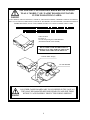
INTRODUCTION OF THE OWNERS MANUAL
SEGA ENTERPRISES, LTD., has for more than 30 years been supplying various innovative and
popular amusement products to the world market. This Owners Manual is intended to provide
detailed descriptions together with all the necessary installation, game settings and parts ordering
information related to VIRTUA NBA U/R Naomi Cabinet type, a new SEGA product.
This manual is intended for those who have knowledge of electricity and technical expertise, especially in ICs, CRTs, microprocessors, and circuit boards. Read this manual carefully to acquire
sufficient knowledge before working on the machine. Should there be a malfunction, non-technical
personnel should under no circumstances touch the interior system. Should the need arise, contact
our main office, or the closest branch office listed below.
SEGA ENTERPRISES, INC. (USA)
Customer Service
45133 Industrial Drive
Fremont, CA 94538
Phone 415-701-6580
Fax
415-701-6594
7:30 am - 4:00 pm, Pacific Standard Time
Monday thru Friday
1
General Precautions
Follow Instructions: All operating and use instructions should be followed.
Attachments: Do not use attachments not recommended by the product manufacturer as they may cause hazards.
Accessories: Do not place this product on an unstable cart, stand, tripod, bracket, or table. The product may fall,
causing serious injury to a child or adult, and serious damage to the product. Use only with a cart, stand, tripod, bracket, or
table recommended by the manufacturer, or sold with the product. Any mounting of the product should follow the
manufacturer’s instructions, and should use only mounting accessories recommended by the manufacturer.
Moving the Product: This product should be moved with care. Quick stops, excessive force, and uneven surfaces
may cause the product to overturn.
Ventilation: Slots and openings in the cabinet are provided for ventilation, to ensure reliable operation of the product
and to protect it from overheating; these openings must not be blocked or covered. The openings should never be blocked
by placing the product in a built-in installation such as a bookcase or rack unless proper ventilation is provided or the
manufacturer’s instructions have been adhered to.
Power Sources: This product should be operated only from the type of power source indicated on the marking label.
If you are not sure of the type of power supply to your location, consult your local power company. For products intended
to operate from battery power or other sources, refer to the operating instructions.
Grounding or Polarization: This product is equipped with a three-wire grounding-type plug, a plug having a third
(grounding) pin. This plug will only fit into a grounding-type power outlet. This is a safety feature. If you are unable to
insert the plug into the outlet, contact your electrician to replace your obsolete outlet. Do not defeat the safety purpose of the
grounding-type plug.
Power Cord Protection: Power-supply cords should be routed so that they are not likely to be walked on or pinched
by items placed upon or against them, paying particular attention to cords at plugs, convenience receptacles, and the point
where they exit from the product.
Overloading: Do not overload wall outlets, extension cords, or integral convenience receptacles as this can result in
a risk of fire or electric shock.
Object and Liquid Entry: Never push objects of any kind into this product through openings as they may touch
dangerous voltage points or short-out parts that could result in a fire or electric shock. Never spill liquid of any kind on the
product.
Servicing: Do not attempt to service this product yourself as opening or removing covers may expose you to dangerous voltage or other hazards. Refer all servicing to qualified service personnel.
Damage Requiring Service: Unplug this product from the wall outlet and refer servicing to qualified service personnel under the following conditions:
a) If the power cord or plug is damaged;
b) If liquid has been spilled, or objects have fallen into the product;
c) If the product has been exposed to rain or water;
d) If the product does not operate normally when following the operating instructions. Adjust only those controls that
are explained in the operating instructions. An improper adjustment of other controls may result in damage and will
often require extensive work by a qualified technician to restore the product to its normal operation;
e) If the product has been dropped or damaged in any way;
f) When the product exhibits a distinct change in performance; this indicates a need for service.
Replacement Parts: When replacement parts are required, be sure the service technician has used replacements parts
specified by the manufacturer or that have the same characteristics as the original part. Unauthorized substitutions may
result in fire, electric shock, or other hazards.
2
Safety Check: Upon completion of any service or repairs to this product, ask the service technician to perform safety
checks to determine that the product is in proper operating condition.
Heat: The product should be situated away from heat sources such as radiators, heat registers, stoves, or other products (including amplifiers) that produce heat.
Lithium Battery- Dispose of batteries only in accordance with the battery manufacturer’s recommendations.
Do not dispose in an open flame condition, since the battery may explode.
Cleaning: When cleaning the monitor glass, use water or glass cleaner and a soft cloth. Do not apply chemicals such
as benzine, thinner, etc.
Location: This an indoor game machine, DO NOT install it outside. To ensure proper usage, avoid installing indoors
in the places mentioned below:
• Places subject to rain/water leakage, or condensation due to humidity;
• In close proximity to a potential wet area;
• Locations receiving direct sunlight;
• Places close to heating units or hot air;
•In the vicinity of highly inflammable/volatile chemicals or hazardous matter;
• On sloped surfaces;
• In the vicinity of emergency response facilities such as fire exits and fire extinguishers;
• Places subject to any type of violent impact;
• Dusty places.
INSTALLATION PRECAUTIONS
• Verify the amperage of the branch circuit outlet before plugging in the power plug. Do not overload the circuit.
• Avoid using an extension cord. If one is required, use an extension cord of type SJT, 16/3 AWG
rated min. 120 VAC, 7A.
• Moving this unit requires a minimum clearance (of doors, etc.) of 32” (W) by 77” (H).
• For the operation of this machine, secure a minimum area of 32” (W) by 42”(D).
REGULATORY APPROVALS
This game has been tested and found to comply with the Federal Communications Commission Rules.
This device complies with Part 15 of the FCC Rules. Operation is subject to the following two conditions: (1) This
device may not cause harmful interference, and (2) this device must accept any interference received, including interference
that may cause undesired operation.
This game has been tested and listed by Underwriters Laboratories, Inc., to ANSI/UL22.
3
1 . PRECAUTIONS TO BE HEEDED FOR OPERATION
In order to prevent accidents, be sure to comply with the following points before and during operation.
PRECAUTIONS TO BE HEEDED FOR OPERATION BEFORE STARTING THE OPERATION
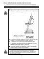
In order to avoid accidents, check the following before starting the operation:
Check if all of the adjusters are in contact with the surface. If they are not,
the cabinet can move and cause an accident.
Do not climb on the product. Climbing on the product can cause falling down
accidents. To check the top portion of the product, use a step.
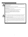
To avoid electric shock, check to see if door & cover parts are closed.
To avoid electric shock, short circuit and or parts damage, do not put the
following items on or in the periphery of the product:
Flower vases, flower pots, cups, water tanks, cosmetics, and receptacles/
containers/vessels containing chemicals and water.
To avoid injury, be sure to provide sufficient space by considering the
potentially crowded situation at the installation location. Insufficient installation space can cause the player to come into contact with or hit others
and result in injury or trouble.
4
PRECAUTIONS TO BE HEEDED DURING OPERATION
To avoid injury and accidents, those who fall under the following catagories are not
allowed to play the game:
* Intoxicated persons
* Those who have high blood pressure or heart problems.
* Those who have experienced muscle convulsion or loss of consciousness when playing
video games, etc.
* Persons susceptible to motion sickness.
* Persons whose acts runs counter to the products warning displays.
* Instruct those who wear high-heeled shoes to refrain from
playing the game by explaining that playing the game with highheeled shoes is very dangerous and likely to cause a potentially
hazardous situation.
To avoid electric shock and short circuit, do not allow customers to put hands and fingers
or extraneous matter in openings of the product or small openings in or around doors.
To avoid electric shock and short circuit, do not allow the customers to unplug the power
plug without a justifiable reason.
Although this product has the accident preventive covering attached to potentially hazardous places where hand and fingers could be caught, small children are unable to perceive
hazards. Use care so that small children do not come close to the product when in play.
Immediately stop such violent acts as hitting and kicking the product. Such violent acts can
cause parts damage and/or falling down, resulting in injury due to fragments and falling
down.
5
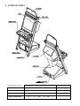
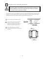
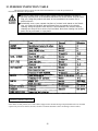
2 . NAME OF PARTS
GAME SPECIFICATIONS
WIDTH in.
LENGTH in.
HEIGHT in.
WEIGHT lbs.
40”
X
70”
X
100”
~ 425 LBS.
CABINET
30”
X
41”
X
71”
325 LBS.
BILLBOARD
30”
X
0.5”
X
12”
2 LBS.
30”
X
58”
X
88”
380 LBS.
DURING SHIPPING
WHEN ASSEMBLED
6
3 . ACCESSORIES
7
THE SHIPMENT METHOD DESCRIBED BELOW APPLIES
TO ALL ‘MODEL 3’ OR ‘NAOMI’ BOARDS CONTAINED
IN THE FOLLOWING GAMES:
LOST WORLD, VIRTUA FIGHTER 3, SUPER GT, SEGA BASS FISHING, STRIKER 2 HARLEY DAVIDSON,
RALLY 2, DAYTONA 2, DIRT DEVILS, HOUSE OF THE DEAD 2, OCEAN HUNTER, STAR WARS TRILOGY,
ZOMBIE REVENGE, CRAZY TAXI, JAMBO SAFARI, F355, VIRTUA TENNIS, VIRTUA NBA
!!NEVER SHIP MODEL 3 / NAOMI GAME
BOARDS OUTSIDE OF CAGE!!
CARTON BOX
601-8928 (1)
Used for transporting the GAME BOARD.
{SUPPLIED WITH YOUR GAME}
DO NOT SHIP GAME BOARD WITHOUT
THIS BOX AS IT MAY DAMAGE THE GAME
BOARD AND VOID YOUR WARRANTY.
“CHECK SIDE” Display
FILTER BOARD
NO OTHER GAMES BOARDS ARE TO BE SHIPPED IN THE CAGE AS
THEY MAY BE DAMAGED BEYOND REPAIR. PLEASE SHIP THEM
WITHOUT CAGE PROPERLY PROTECTED DURING SHIPPING.
8
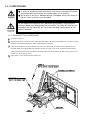
4 . ASSEMBLING AND INSTALLATION
Assembling should be performed as per this manual. Since this is a
complex machine, erroneous assembling may cause damage to the
machine, or malfunctioning to occur.
When assembling, be sure to perform work by plural persons.
Depending on the assembly work, there are some cases in which
performing the work by a single person can cause personal injury or
parts damage.
When carrying out the assembly work, follow the procedure in the following 5-item sequence:
1
ASSY OF BILLBOARD
2
SECURING IN PLACE (ADJUSTER ADJUSTMENT)
3
POWER SUPPLY
4
ASSEMBLING CHECK
Note that the tools such as a phillips screwdriver and wrench for M16 hexagon bolt w/24 mm width
across flats are required for the assembly work.
Perform conector connection securely. Insufficient insertin can cause
electrical shock or short circuit.
Be careful so as not to damage wirings. Damaged wiring can cause
electric shock or short circuit.
9
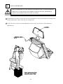
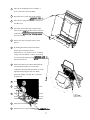
1
ASSY OF BILLBOARD
Due to its large size, it is very difficult for one person alone to install the billboard,
Make sure 2 or more persons are available to perform this work. Attempting to
perform the installation alone can cause an accident.
1 Mount Billboard on cabinet by ensuring the front lip of the Billboard is securely placed under the mounting bracket
already installed on the cabinet. Fasten with the 3 hexagon bolts.
2 Connect all of the 4 connectors inside the Billboard box (This needs to be done prior to final installation of
Billboard Assy).
10
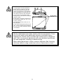
2
SECURING IN PLACE (ADJUSTER ADJUSTMENT)
Be sure to have all the Adjusters make contact with the surface. Unless the Adjusters come into contact with the surface, the Cabinet
can move of itself, causing an accident.
This machine has 4 each of casters and adjusters (shown below). When the installation position is determined, cause
the adjusters to come into contact with the floor directly, make adjustments in a manner so that the casters will be
raised approximately 5mm. from the floor and make sure that the machine position is level.
1
Move the machine to the installation position.
2
Cause all of the leg levelers to make contact
with the floor. By using a wrench, make
adjustments in the height of the leg adjusters to
ensure that the machine's position is level.
3
After making adjustments, fasten the leg
adjuster nut upward and secure the height of the
leg adjuster.
11
3
POWER SUPPLY
Ensure that the power cord is not exposed on the surface (passage,
etc.). If exposed, they can be caught and are susceptible to damage.
If damaged, the cord can cause an electric shock or short circuit.
Ensure that the wiring position is not in the customer's passage way
or the wiring has protective covering.
Connect the game to the power supply and turn on power to the game. Before connecting power supply be sure that
power switch is off
1 Turning the AC unit’s main switch on will cause the machine
to start the power check and network check automatically.
12
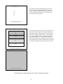
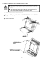
4
ASSEMBLING CHECK
The TEST MENU allows for each part of the cabinet to be checked, the Monitor to be adjusted, and the coin and game
related various functions to be performed.
Selecting the MEMORY TEST on the test mode menu screen causes the on-board memory to be tested automatically.
The game board is satisfactory if the display beside each IC No. shows GOOD.
Selecting the INPUT TEST on the Test Mode menu screen
causes the screen (on Which each switch adnV.R. are tested)
to be displayed. Press each switch. For the coin switch test,
insert a coin from the coin inlet with the coin chute door
being open. If the display beside each switch indicates
“ON”, the switch and wiring connections are satisfactory.
Check the display of V.R. value for steering wheel and
accelerator & brake. If the V.R. values are not satisfactory,
make adjustments as neccesary.
In the OUTPUT TEST mode, carry out lamp test to ensure
that each lamp lights up satisfactory.
13
SOUND
TEST
VOICE
EFFECT
B.G.M.
In the TEST mode, selecting SOUND TEST causes the
screen, on which sound related BD and wiring connections are tested, to be displayed. Be sure to check if the
sound is satisfactorily emitted from each of speaker and
the sound volume is appropriate.
>EXIT
SELECT WITH SERVICE BUTTON AND
PRESS TEST BUTTON TO EXIT
C.R.T. TEST 1/2
RED
GREEN
BLUE
In the TEST mode menu, selecting C.R.T. TEST allows the
screen (on which the projector is tested) to be displayed.
Although the projector adjustments have been made at the
same time of shipment from the factory, color deviation,
etc., may occur due to the effect caused by geomagnitism,
the location building’s steel frames and other game machines in the periphery. By watching the test mode screen,
make judgement as to whether an adjustment is needed. If it
is neccessary, adjust the projector by refering to Section 9.
WHITE
PRESS TEST BUTTON TO CONTINUE
C.R.T. TEST 2/2
PRESS TEST BUTTON TO CONTINUE
Perform the above inspections also at the time of monthly inspection.
14
5 . PRECATIONS TO BE HEEDED WHEN MOVING THE MACHINE
When moving the machine, be sure to pull out the plug from
the power supply. Moving the machine with the plug as is
inserted can damage the power cord and cause a fire or electric shock.
When moving the machine on the floor, retract the Adjusters
and ensure that Casters make contact with the floor. During
transportation, pay careful attention so that Casters do not
tread power cords. Damaging the power cords can cause an
electric shock and/or short circuit.
When lifting the cabinet, be sure to hold the catch portions or
bottom part. Lifting the cabinet by holding other portions can
damage parts and installation portions, due to the empty
weight of the cabinet, and cause personal injury.
Use care when handling glass made parts. When the glass is damaged, fragments of glass can cause injury
15
6 . CONTENTS OF GAME
The following explanations apply to the case the product is functioning satisfactorily. Should there be any moves
different from the following contents, some sort of faults may have occured. Immediately look into the cause of the
fault and eliminate the cause thereof to ensure satisfactory operation.
OUTLINE OF GAME
FROM AMONG THE 29 NBA TEAMS, SELECT YOU R FAVORITE TEAM
When a single play mode is selected, you battle against the computer controlled players in a tournament imagined
real NBA playoffs.
If the score you have earned is greater than that of the opposing team at the game end, you can proceed to the next
stage. In case of a tie score or less the game is over.
A player can buy into play a versus game, and the game can be continued up to the 4th quater. Upon finishing a
quarter, the player who has earned greater score can proceed to the next game. The player who lost the game can
also play the game by executing a continue.
In case that a quarter ends in a tie, the player who has earned greater score in that quarter can proceed to the next
quarter.
HOW TO OPERATE
Operate the lever and the 2 buttons to play the game.
LEVER:
movement
BLUE BUTTON:
(offense) pass
(defense) steal
RED BUTTON:
(offense) shoot
(defense) block shot/rebound
HOW TO PLAY
OFFENSE:
JUMP SHOT
When standing still, keep pressing down the shoot button to jump. Release the shoot button to shoot
the ball.
RUNNING JUMPER
Press the shoot button to do a running jumper while dribbling.
If the defense stops your dribble, you will shoot a regular jump shot. You can perform a dunk shot
depending on the distance to the goal or the timing of a shot.
PASS:
You can pass to any of your teammates by inclining the Lever in the direction of the intended player,
and then pressing the pass button.
DEFENSE:
BLOCK SHOT
You can interrupt an opposing player’s shot if you press the block button timely in accordance to his
jump. You can decrease the probability of making the shot, even if you can not block the shot.
STEAL
When you are very close to the opposing player dribbling, if you press the steal button timely, you
can steal the ball. You can also steal the ball if you timely press the steal button at a certain position
when an opposing player is passing the ball.
16
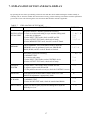
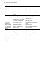
7 . EXPLANATION OF TEST AND DATA DISPLAY
By operating the switch unit, periodically perform the tests and data check. When installing the machine initially or
collecting cash, or when the machine does not function correctly, perform checking in accordance with the explanations
given in this section. The following shows tests and modes that should be utilized as applicable.
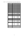
TABLE 7
EXPLANATION OF TEST MODE
ITEMS
DESCRIPTION
When the machine is installed, perform the following:
INSTALLATION 1. Check to see that each setting is as per standard setting made
at the time of shipment.
OF MACHINE
2. In the INPUT TEST mode, check each SW and VR.
3. In the OUTPUT TEST mode, check each of lamps.
4. In the MEMORY TEST mode, check ICs on the IC Board.
MEMORY
CONTROL
SYSTEM
Choose MEMORY TEST in the MENU mode to allow the
MEMORY test to be performed. In this test, PROGRAM
RAMs, ROMs, and ICs on the IC Board are checked.
SECTIONS
7 - 10, 7 - 11
7-6
7-7
7 - 3, 7 - 4
7 - 3, 7 - 4
Periodically perform the following:
1. MEMORY TEST
2. Ascertain each setting.
3. In the INPUT TEST mode, test the CONTROL device
4. In the OUTPUT TEST mode, check each of lamps.
7 - 10, 7 - l1
1. In the INPUT TEST mode, check each SW and VR.
2. Adjust or replace each SW and VR.
3. If the problem can not be solved yet, check the CONTROL’s moves.
7-6
MONITOR
In the MONITOR ADJUSTMENT mode, check to see if the
MONITOR adjustment is appropriately made.
IC BOARD
1. MEMORY TEST
2. In the SOUND TEST mode, check the sound related ROMs.
DATA CHECK
Check such data as game play time and histogram to adjust the
difficulty level, etc
17
7-6
7-7
8
12
7-2
7-8
7 - 15
7 - 1 SWITCH UNIT AND COIN METER
Never touch places other than those specified. Touching places not
specified can cause electric shock and short circuit.
Adjust to the optimum sound volume by considering the environmental
requirements of the installation location.
If the COIN METER and the game board are electrically disconnected,
game play is not possible.
Open COIN CHUTE DOOR, and the
switch unit shown appears. The function
of each switch is as follows:
SWITCH UNIT
1
SPEAKER VOLUME:
Sound Volume can be adjusted for the 2 Speakers.
2
WOOFER VOLUME:
Sound Voume can be adjusted for the WOOFER.
3
TEST BUTTON:
For the handling of the TEST BUTTON, refer to the following pages.
4
SERVICE BUTTON:
Gives credits without registering on the coin meter.
5
DEMAG. SWITCH:
Eliminates the on-screen color unevenness due to magnetization of CRT. First use this
SW before performing the monitor’s color adjustment.
18
7 - 2 SYSTEM TEST MODE
The contents of setings chnaged in the TEST mode are stored when the TEST mode
is finished from EXIT in the MENU mode. If the power is turned off before the TEST
mode is finished, the contents of setting chnage become ineffective.
Executing “BACKUP DATA CLEAR” in the SYSTEM TEST MODE does not clear the
BOOKKEEPING data in the GAME TEST MODE.
Entering the TEST mode clears fractional number of coins less than one credit and
BONUS ADDER data.
The SYSTEM TEST mode mainly allows for IC Board functioning check, monitor adjustment, coin assignments, etc.
For details, refer to NAOMI SERVICE MANUAL. The following assignments, however, should be designated for this
product.
CABINET TYPE:
1 PLAYER (S)
MONITOR TYPE:
HORIZONTAL
COIN CHUTE TYPE:
COMMON
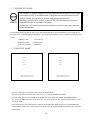
7 - 3 GAME TEST MODE
SOUND TEST
SOUND TEST
VOICE
VOICE
EFFECT
EFFECT
B.G.M
B.G.M
>EXIT
>EXIT
SELECT WITH SERVICE BUTTON
PRESS TEST BUTTON TO EXIT
SELECT WITH SERVICE BUTTON
PRESS TEST BUTTON TO EXIT
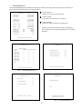
Press the TEST button to display the SYSTEM TEST MODE MENU.
By pressing the SERVICE button, move the arrow (->) to select the GAME TEST MODE.
Press the TEST button to enter GAME TEST MODE. The screen displays the GAME TEST MODE MENU.
By pressing the SERVICE button, move the arrow (->) to select the desired item. Press the TEST button to execute
the selected item.
Select EXIT and press the TEST button to exit from the GAME TEST MODE and return to the SYSTEM TEST
MODE MENU. Further, select EXIT and press the TEST button to finish SYSTEM TEST MODE and return to the
normal mode.
19
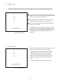
7 -4 INPUT TEST
Select INPUT TEST to have the screen shown below appear and to observe the status of each switch and the
value of each V.R. on the Control Panel. Periodically check the status of each switch and V.R. on this screen.
SOUND TEST
VOICE
EFFECT
B.G.M
>EXIT
By pressing each switch, if the display on the right-hand side
of the name of each switch changes to ON from OFF, the SW
and the wiring connections are satisfactory.
To check CHUTE 1 & CHUTE 2 coin switches, open the
COIN CHUTE DOOR and insert a coin(s) in the slot.
Press either the TEST BUTTON and the START BUTTON
to return to the test menu.
SELECT WITH SERVICE BUTTON
PRESS TEST BUTTON TO EXIT
FIG. 7.4 INPUT TEST
As a standard, refer to the following for each of the Volume’s
adjustment. By operating the Handle (Steering Wheel) and
Pedal, if the V of each Volume guage smoothly moves as the
corresponding value varies ina natural manner, then it is
satisfactory.
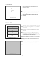
7 - 5 OUTPUT TEST
SOUND TEST
VOICE
EFFECT
B.G.M
>EXIT
Choose OUTPUT TEST to cause the following lower screen
to appear. In this test, check the status of each lamp.
The right-hand side “ON” & “OFF” display of START
LAMP automatically alternates. The lamp lights up
when “ON” is displayed and goes off when “OFF” is
displayed. Check to ensure that the lamp lights up and
goes off in consistency with the display of “ON” and
“OFF”.
Press the TEST button to return to the TEST MENU.
SELECT WITH SERVICE BUTTON
PRESS TEST BUTTON TO EXIT
FIG. 7.5 OUTPUT TEST
20
7 - 6 SOUND TEST
SOUND TEST
This test mode allows each sound related board and
speaker to be checked.
AUTO
SE
B.G.M & VOICE
>EXIT
Press the Service Button to select the sound to be tested,
and press the Test Button to have the selected Sound
Test screen appear.
Select EXIT and press the Test Button to return to the
Test Menu.
SELECT WITH SERVICE BUTTON
PRESS TEST BUTTON TO EXIT
FIG. 7.6 SOUND TEST
7 - 7 C.R.T. TEST
C.R.T. TEST 1/2
RED
GREEN
BLUE
Select C.R.T. TEST to cause the MONITOR to display the
screen shown left, allowing MONITOR adjustment status
to be checked.
Periodically check the MONITOR adjustment status on
this screen.
The screen (1/2) enables color adjustment check to be
performed. The color bar of each of the 4 colors, i.e.,red,
green, blue, and white, is the darkest at the extreme left and
becomes brighter towards the extreme right.
WHITE
Press the TEST BUTTON to shift to the next screen (2/2).
PRESS TEST BUTTON TO CONTINUE
The screen (2/2) allows screen size and distortion to be
tested.
C.R.T. TEST 2/2
Check if the CROSSHATCH FRAME LINE goes out of
the screen and if the crosshatch lines are distorted.
Press the TEST BUTTON to return to the MENU mode.
PRESS TEST BUTTON TO EXIT
FIG. 7.7 C.R.T. TEST
21
7 - 8 VS. TEAM DATA
In this test, the Team Data in the VS. mode can be checked.
VS> TEAM DATA
USE:
USE:
Displays team selection frequency.
WIN:
Displays each team’s total number of victories in versus
games.
WIN:
DRAW:
LOSE:
DRAW:
Displays each team’s total number of draws in versus
games.
>EXIT
PRESS TEST BUTTON TO EXIT
LOSE:
Displays each team’s total number of losses in versus
games.
FIG. 7.8 VS. TEAM DATA
22
7 - 9 GAME ASSIGNMENTS
Selecting the GAME ASSIGNMENTS in the MENU mode causes the present game settings
to be displayed and also the game settings changes (game difficulty, etc.) can be made. Each
item displays the following content.
SETTING CHANGE PROCEDURE
1
2
3
Press the SERVICE BUTTON to move the “>” to the desired item.
Choose the desired setting change item by using the TEST BUTTON.
To return to the MENU mode, move the arrow to EXIT and press the TEST BUTTON.
GAME ASSIGNMENTS
START TIME
TIME DIFICULTY
GAME DIFFICULTY
50
4/8
4/8
>EXIT
SELECT WITH SERVICE BUTTON
AND PRESS TEST BUTTON TO EXIT
TIME SET
The time for one play can be set within a range of 1’15” and
3’00”.
ONE MATCH MODE
Select from among OFF, 1 GAME, and FULL GAME.
OFF- This is the standard setting
1 GAME- Game is over when one game is finished. This
option is for some sorts of event such as game competition, etc.
FULL GAME- Regardless of communication mode 1P (against
the computer) mode, the game starts at the 1st quarter.
GAME DIFFICULTY
Sets the difficulty level in 4 categories, i.e., EASY, NORMAL,
HARD, and HARDEST.
CONTINUE TYPE
Game continue setting. “CHARGE” and “WINNER NO
CHARGE” settings are available. The standard setting is
WINNER NO CHARGE.
WINNER NO CHARGE>The player who wins the versus
game can continue to play.
CHARGE>In this option, each time game is finished, the
player who plays the game against the computer is urged to
continue whether he wins or not. In versus game, the players
are urged to continue each time quarter ends regardless of win
or loss.
VS. WIN TO CHARGE>In this option, when played against a
computer, the player is urged to continue each time when game
is finished. When played in VS. mode, the player who wins the
game can continue the game.
23
7 - 10 COIN ASSIGNMENTS
The “COIN ASSIGNMENTS” mode permits you to set the start number of credits, as well as the basic numbers
of coins and credits. This mode expresses “how many coins correspond to how many credits.”
SETTING CHANGE PROCEDURE
Setting changes cannot be stored unless the TEST BUTTON is pressed
while the arrow is on EXIT.
1
Press the SERVICE BUTTON to move the arrow to the desired item.
2
Choose the desired setting change item by using the TEST BUTTON.
3
To return to the MENU mode, move the arrow to EXIT and press the TEST BUTTON.
7 - 10 COIN ASSIGNMENTS
COIN ASSIGNMENTS
COIN/CREDIT SETTING
#1
CHUTE#1
1 COIN
1 CREDIT
CHUTE#2
1 COIN
1 CREDIT
ADDITIONAL SETTING
MANUAL SETTING
>EXIT
COIN/CREDIT SETTING
Sets the CREDITS increase increment per coin insertion.
There are 27 setings from #1 to #27, expressed in XX
CREDIT as against XX COINS inserted. (TABLE 7.10a,
7.10b) #27 refers to FREE PLAY.
When the COIN CHUTE TYPE is set to INDIVIDUAL,
there are some setting numbers not displayed as indicated in
TABLE 7.10b.
MANUAL SETTING
This allows credit increase setting as against coin insertion
to be further set in the manner finer than COIN/CREDIT
SETTING (refer to TABLE 7.10c).
SELECT WITH SERVICE BUTTON
AND PRESS TEST BUTTON
24
TABLE 7.10a COIN/CREDIT SETTING (COIN CHUTE COMMON TYPE)
SETTING
SETTING #1
SETTING #2
SETTING #3
SETTING #4
SETTING #5
SETTING #6
SETTING #7
SETTING #8
SETTING #9
SETTING #10
SETTING #11
SETTING #12
SETTING #13
SETTING #14
SETTING #15
SETTING #16
SETTING #17
SETTING #18
SETTING #19
SETTING #20
SETTING #21
SETTING #22
SETTING #23
SETTING #24
SETTING #25
SETTING #26
SETTING #27
FUNCTIONING OF CHUTE#1
1 COIN
1 CREDIT
1 COIN
2 CREDITS
1 COIN
3 CREDITS
1 COIN
4 CREDITS
1 COIN
5 CREDITS
1 COIN
2 CREDITS
1 COIN
5 CREDITS
1 COIN
3 CREDITS
1 COIN
4 CREDITS
1 COIN
5 CREDITS
1 COIN
6 CREDITS
2 COINS
1 CREDIT
1 COIN
1 CREDIT
1 COIN
2 CREDITS
1 COIN
1 CREDIT
2 COINS
3 CREDITS
1 COIN
3 CREDITS
3 COINS
1 CREDIT
4 COINS
1 CREDIT
1 COIN
1 CREDIT
2 COINS
2 CREDITS
3 COINS
3 CREDITS
4 COINS
5 CREDITS
1 COIN
5 CREDITS
5 COINS
1 CREDIT
1 COIN
2 CREDITS
2 COINS
1 CREDIT
4 COINS
2 CREDITS
5 COINS
3 CREDITS
1 COIN
3 CREDITS
1 COIN
1 CREDIT
2 COINS
2 CREDITS
3 COINS
3 CREDITS
4 COINS
4 CREDITS
5 COINS
6 CREDITS
1 COIN
1 CREDITS
FREE PLAY
25
MANUAL SETTING
Selecting MANUAL SETTING in the COIN ASSIGNMENTS mode displays the following screen.
MANUAL SETTING
COIN TO CREDIT
1 COIN
BONUS ADDER
NO BONUS ADDER
1
1 CREDIT
2
COIN CHUTE #1 MULTIPLIER
1 COIN COUNTS AS 1 COIN
COIN
1
2
3
CREDIT 1
2
3
4
4
5
5
6
6
7
7
8
8
9
9
COIN CHUTE #2 MULTIPLIER
1 COIN COUNTS AS 1 COIN
COIN
1
2
3
CREDIT 1
2
3
4
4
5
5
6
6
7
7
8
8
9
9
3
>EXIT
SELECT WITH SERVICE BUTTON
AND PRESS TEST BUTTON
FIG. 7.11b MANUAL SETTING
1 Determines Coin/Credit setting.
2 This sets how many coins should be inserted to obtain one Service Coin.
3 This sets how many tokens one coin represents.
Table 7.10c MANUAL SETTING
COIN TO CREDIT
1 COIN
2 COINS
3 COINS
4 COINS
5 COINS
6 COINS
7 COINS
8 COINS
9 COINS
BONUS ADDER
NO BONUS ADDER
2 COINS GIVE 1 EXTRA COIN
3 COINS GIVE 1 EXTRA COIN
4 COINS GIVE 1 EXTRA COIN
5 COINS GIVE 1 EXTRA COIN
6 COINS GIVE 1 EXTRA COIN
7 COINS GIVE 1 EXTRA COIN
8 COINS GIVE 1 EXTRA COIN
9 COINS GIVE 1 EXTRA COIN
COIN CHUTE MULTIPLIER
1 COIN COUNTS AS 1 COIN
1 COIN COUNTS AS 2 COINS
1 COIN COUNTS AS 3 COINS
1 COIN COUNTS AS 4 COINS
1 COIN COUNTS AS 5 COINS
1 COIN COUNTS AS 6 COINS
1 COIN COUNTS AS 7 COINS
1 COIN COUNTS AS 8 COINS
1 COIN COUNTS AS 9 COINS
26
1 CREDIT
1 CREDIT
1 CREDIT
1 CREDIT
1 CREDIT
1 CREDIT
1 CREDIT
1 CREDIT
1 CREDIT
7 - 11 BOOKKEEPING
Choosing BOOKKEEPING in the MENU mode displays the data of operating status up to the present are shown on 2
pages. Press the TEST BUTTON to proceed to PAGE 2/2.
BOOKKEEPING
COIN CHUTE#*:
Number of coins put in each Coin Chute.
PAGE1/5
COIN CHUTE #1
COIN CHUTE #2
TOTAL COINS
XXXXXXXXXXX
XXXXXXXXXXX
XXXXXXXXXXX
COIN CREDITS
SERVICE CREDITS
TOTAL CREDITS
XXXXXXXXXXX
XXXXXXXXXXX
XXXXXXXXXXX
NUMBER OF GAMES
XXXXXXXXXXX
TOTAL
TIME
1P PLAY
TIME
VS. PLAY
TIME
AVERAGE PLAY
LONGEST PLAY
SHORTEST PLAY
PLAY TIME RATE
VS. PLAY RATE
XDXXHXXMXXS
XDXXHXXMXXS
XDXXHXXMXXS
XXMXXS
XXMXXS
XXMXXS
XXX
XXX
TIME
TIME
TIME
TOTAL COINS:
Total number of activations of Coin Chutes.
COIN CREDITS:
Number of credits registered by inserting coins.
In Page 2/5, Histogram of Number of Play as against Play
Time is displayed. For setting the DIFFICULTY, refer to this
histogram.
PRESS TEST BUTTON TO CONTINUE
FIG. 7.11a BOOKKEEPING (1/5)
BOOKKEEPING PAGE 2/5
BOOKKEEPING 3/5
TIME HISTOGRAM
COURSE
BEGINNER ADVANCED EXPERT
~2M29S
0
0
0
2M30S~2M44S
0
0
0
2M45S~2M59S
0
0
0
3M00S~3M14S
0
0
0
3M15S~3M29S
0
0
0
3M30S~3M44S
0
0
0
3M45S~3M59S
0
0
0
4M00S~4M14S
0
0
0
4M15S~4M29S
0
0
0
4M30S~
0
0
0
TOTAL GAME COUNT
XXX
CONTINUE GAME COUNT
XXX
PLAYER 1 GAME COUNT
XXX
PLAYER 2 GAME COUNT
XXX
PRESS TEST BUTTON TO CONTINUE
PRESS TEST BUTTON TO CONTINUE
FIG. 7.11c BOOKKEEPING (3/5)
FIG. 7.11b BOOKKEEPING (2/5)
BOOKKEEPING 5/5
BOOKKEEPING PAGE 4/5
DRAW COUNT
XX
VS. WINS MAXIMUM
XX
VS. WINS HISTOGRAM
XX
TOURNAMENT REPORT
>EXIT
SELECT WITH SERVICE BUTTON
PRESS TEST BUTTON TO EXIT
PRESS TEST BUTTON TO CONTINUE
FIG. 7.11d BOOKKEEPING (4/5)
FIG. 7.11e BOOKKEEPING (5/5)
27
7 - 12 BACKUP DATA CLEAR
Clears the contents of BOOKKEEPING and high
score player ranking entry.
BACKUP DATA CLEAR
YES (CLEAR)
>NO (CANCEL)
When clearing, bring the arrow to “YES” and when
not clearing, to “NO”, by using the SERVICE
BUTTON, and push the TEST BUTTON.
When the data has been cleared, “COMPLETED”
will be displayed. Bring the arrow to “NO” and
press the TEST BUTTON to cause the MENU
mode to return on to the screen.
Note that the contents of the GAME SETTING,
COIN SETTING, and BOARD SETTING are not
affected by BACKUP DATA CLEAR operation.
SELECT WITH SERVICE BUTTON
PRESS TEST BUTTON TO EXIT
FIG. 7.12 BACKUP DATA CLEAR
28
8. CONTROL PANEL
In order to prevent an electric shock and short circuit, be sure to turn power off
before performing work by touching the interior parts of the product.
Be careful so as not to damage wirings. Damaged wiring can cause an electric shock
or short circuit accident.
Do not touch undesignated areas. Touching undesignated areas can cause electrical
shock or short circuit.
This work should be performed by the Location’s Maintenance Man or Serviceman.
Performing work by non-technical personnel can cause electric shock hazard.
When closing the Control Panel, be very careful so as not to have hand and fingers
pinched in.
8 - 1 ADJUSTING AND REPLACING THE VOLUME
1
Turn power OFF by using the Main SW of AC Unit or SUB PWR SPLY SW inside the SERVICE DOOR.
2
Unlock the lock on theback of the Control Panel Base, and open the Control Panel Base.
3
There are 6 Connectors on the monitor side of the Base interior. Disconnect all of the 6 Connectors. Depending on
the game used, however, not all of the 6 connectors may have been connected.
4
By removing the 6 sets of Carriege bolts and Flange Nuts, the Control Panel can be removed from the Base. At
this time, be very careful so as not to damage wiring.
29
HOW TO REPLACE INSTRUCTION SHEET
1
Turn power OFF by using the Main SW of AC Unit or the SUB PWR SUPPLY SW inside the SERVICE DOOR.
2
Unlock the lock on the back of the Control Panel Base, and open the Control Panel Base.
3 From inside the Control Panel Base, remove the 4 L WASHERS from both sides of INSTRUCTION COVER by
removing the screw from each.
4
Remove the Instruction Cover to replace the Instruction Sheet.
By using ther reversed procedure, install the Instruction Cover by securing the 4L WASHERS. Pay careful
attention to the method securing the L WASHERS.
30
9 . COIN SELECTOR
HANDLING THE COIN JAM
If the coin is not rejected when the REJECT BUTTON is pressed, open the coin chute door
and open the selector gate. After removing the jammed coin, put a normal coin in and check
to see that the selector correctly functions.
CLEANING THE COIN SELECTOR
1
2
3
4
5
6
GATE
The coin selector should be cleaned
once every 3 months. When cleaning,
follow the procedure below:
Turn the power for the machine OFF.
Open the coin chute door.
Open the gate and dust off by using a
soft brush (made of wool, etc.).
Remove and cleen smears by using a
soft cloth dipped in water or diluted
chemical detergent and then squeezed
dry.
Remove the CRADLE.
When removing the retaining ring(Ering), be very careful so as not to bend
the shaft.
Remove stain from the shaft and pillow
portions by wiping off with a soft cloth,
etc.
After wiping as per #5 above, further
apply a dry cloth, etc. to cause the coin
selector to dry completely.
FIG. 11a
CRADLE
FIG.11b
Never apply machine oil, etc. to
the coin selector
After cleaning the Coin Selecting,
Insert a regular coin in the normal
working status and ensure that
the Selector correctly functions.
COIN INSERTION TEST
Once a month, when performing the COIN SW
TEST, simultaneously check the following:
Does the Coin Meter count satisfactorily?
Does the coin drop into the Cashbox correctly?
Is the coin rejected when inserted while keeping
the REJECT BUTTON is pressed down?
Insert a coin
while keeping
the Reject
Button pressed
down and check
if it is
rejected.
COIN METER
FIG. 11c
31
OPTIONAL DOLLAR BILL ACCEPTOR
THE COIN DOOR ASSEMBLY USED ON VIRTUA TENNIS COMES
EQUIPPED TO ACCEPT A DOLLAR BILL ACCEPTOR. ALL NEEDED
WIRING CONNECTIONS ARE CONVIENENTLY LOCATED INSIDE THE
GAME FOR THIS APPLICATION.
THE COIN DOOR CAN ACCCOMMODATE THE FOLLOWING
VALIDATORS:
HOLE POSITION#1
(FORWARD-MOST POSITION)
Mars 2000 series
HOLE POSITION#2
Mars 2000 series
DBV45 (JCM)
HOLE POSITION #3
CURRENTLY NOT USED
HOLE POSITION #4
DSI01*
*The back flange on the chute can be removed for hold position #4.
If the flange is not removed, it may interfere with the back of the
cabinent.
The frame and cashbox enclosure on this coindoor has been modified to accomodate a Mars 2000 series
upstacker. A 2000 series stacker can be added by simply removing the top two entry door and replacing it with a one
entry door with a cut-out for a stacker. This one entry door can be ordered through Coin Controls or one of Coin Controls
authorized distributors. The part number is 91-4000-01. The Mars stacker can be obtained through an autherized Mars
distibutor.
It should also be noted that this unit comes equipped with security hasp that surrounds the two bottom doors where the
cash box is located. This is to ensure that the monies within are not tampered with, except by the operator.
32
33
10. MONITOR
When performing such work as installing and removing the monitor, inserting and disconnecting the external connectors to and from monitor, be sure to disconnect the power connector
(plug) before starting work. Proceeding the work without following this instruction can cause
electric shock of malfunctioning.
Using the monitor by converting it without obtaining a prior permission is not allowed. SEGA
shall not be liable for any malfunctioning and accident caused by said conversion.
Primary side and secondary side
The monitor’s circuit which is divided into the Primary
side and secondary side, is electrically isolated. Do
not touch the primary side and the secondary side
simultaneously. Failing to observe the instruction can
cause electric shock, and this is very dangerous.
When making monitor adjustments, use a nonconductive driver and make adjustment without
touching any other part other than the Adjustment
V.R. and Knob. Also, be sure not to cause a shortcircuit to the Primary side and the Secondary side. If
short-circuited, it can cause electric shock or malfunctioning, which is very dangerous.
High tension Voltage
Some of the parts inside the monitor are subject to high-tension voltage in excess of 20,000
volts and very dangerous. Therefore, do not touch the monitor interior. Should soldering &
paper wastes, etc. be mixed in the monitor, turn the power off so as not to cause malfunctioning or fire hazard.
Connecting the CRT and PCB
For combining the CRT and PCB, use the specified part No. to maintain the status of adjustments made at the factory. The anode of the CRT itself will be accumulitavely charged as time
elapses, generating high tension voltage which is very dangerous. The monitor should be used
with the Chassis, CRT and PCB assembled. When repair, etc. is required at the time of malfunctioning, be sure to send it in an “as assembled” condition. If these are disassembled, what’s
charged to said high tension voltage can be discharged, causing a very hazardous situation.
Therefore, under no circumstances should it be disassembled.
Static Electricity
Touching the CRT surface sometimes causes you to slightly feel electricity. This is because the
CRT surfaces are subject to static and will not adversly affect the human body.
Installation and removal
Ensure that the Magnetizer Coil, FBT (Fly-Back Transformer), Anode Lead and Focus Lead are
not positioned close to the sheet metal work’s sharp edges, etc. and avoid damaging the
insulated portions so as not to cause an electric shock and malfunctioning. (For the name of
parts, refer to the above figures.)
34
For the purpose of static prevention,
special coating is applied to the CRT
face of this product. To protect the
coating, pay attention to the following
points. Damaging the coating film can
cause electric shock to the customers.
For the caution to be heeded when
clearing, refer to the Section of Periodic
inspection Table.
Do not apply or rub with a hard item (a
rod with pointed edge, pen, etc.) to or
on C.R.T. surfaces.
Avoid applying stickers, seals, etc. on
the C.R.T. face.
Do not remove aluminum foils from the
C.R.T. corners. Removing the aluminum
foils can cause static prevention effects
to be lowered.
Monitor adjustments have been made at the time of shipment. Therefore do not make further adjustment without a justifiable reason.
Adjusting the monitor which contains high tension parts is dangerous
work. Also, an erroneous adjustment can cause deviated synchronization and image fault, resulting in malfunctioning.
When making adjustment, utilize a resinous Alignment Rod. Servicing
with bare hands or using conductive tools can cause electric shock.
35
When performing such work as monitor installation/removal, or inserting /disconnectiing the
exteernal Connector connected to teh monitor and it’s interiror, first be sure to disconect thje
power connector (plug). Working witht eh power plug as is connected can cause electric shock or
malfunctioning.
When performing work, be very careful. To avoid electric shock accidents, etc., personnel other
tha those who have technical expertise are not allowed to perform this work.
Perform work bny following the procedure herein stated. Failing to comply with these instructions
can cause an electric shock accident.
Be sure to use 2 or more workers for this work. Performing work by work person can cause injury
or parts damage.
To ensure performing the work safety, provide sufficient space.
Working in places with narrow space can cause injury or working errors.
Be careful so as not to damage wirings. Damaged wiring can cuase an electric shock or short
circuit accident.
Do not touch places ther than those specified. Touching places other than those specified can
cuase an electric shock or short circuit accident.
After the vertical/horizontal transposition of the MONITOR (GAME BD
replacement), monitor adjustments may be required.
For perfroming the monitor’s vertical/horzontal transposition in the manner consistent with the Game Board, follow the
procedure below:
1
After turning power off by using the Main SW of
AC Unit or the SUB PWR SPLY SW inside the
SERVICE DOOR, unplug the power plug from the
socket outlet.
2
Open the Control Panel Base.
3
By using a flat blade type screwdriver, etc., remove
the 4 Screw Caps from the Front Panel.
36
1
Take out the 4 tamperproof screws and the 2
screws, and remove the Front Panel.
2
Disconnect the 2 Connectors for the speakers.
3
Take out the 6 Tamperproof screws, and remove
the CRT Cover.
4
Disconnect the 2 Connectors connected to the
frame on the back side of CRT and the Connector
connected to the Printed Circuit Board to loosae
the secured wiring.
5
Remove the nuts securing the corners of the
monitor.
6
By holding the monitors sheet metal frame
portion, pull out from the cabinet.
At this time, be very careful so as not to damage
wiring. Since the monitor is a heavy item, lift up
by 2 persons and another person is to support the
monitor from the rear.
7
Install the monitor to the cabinet. When placing
the cabinet horizontally, the 2 Connectors
connected to the aforementioned frame are on the
right-hand side facing the CRT face. When
placing the cabinet vertically, the 2 Connectors
are underside.
8
Secure the monitor with the 4 nuts.
9
Connect the aforementioned 3 connectors, and
secure wiring.
10
Take out the 8 screws, remove the mask from the
Front Panel, and change the installation direction
of Mask so as to match the monitor.s orientation.
11
Install the Front Panel and CRT Cover.
12
Install the 4 screw caps to the Front Panel.
37
38
39
11. REPLACEMENT OF FLUORESCENT LAMP
When performing the work, be sure to turn power off. Working
with power on can cause an electric shock or short circuit accident.
The Fluorescent Lamp, when it gets hot, can cause burns. Be
very careful when replacing the Fluorescent Lamp.
11 -1 REPLACEMENT OF FLUORESCENT LAMP
1
Turn power OFF by using the Main SW or the SUB PWR SPLY SW inside the SERVICE
DOOR.
2
Open the Control Panel.
40
3 By using a Flat-blade screwdriver, etc.remove the 4 Screw
Caps from the Front Panel.
4 Take out the 4 Tamperproof screws and 2 screws, and remove the Front Panel to replace the Fluorescent Lamp.
41
12. PERIODIC INSPECTION TABLE
The items listed below require periodic check and maintenance to retain the performance of
this machine and ensure safe operation.
Be sure to check once a year to see if Power Cords are damaged, the plug is
securley inserted, dust is accumulated between the Socket Outlet and the Power
Plug, etc. Using the product with dust as is accumulated can cause a fire or
electrical shock.
Periodically once a year, request the place of contact herin stated or the Distributer, etc. where the product was purchased from, as regards to the interior
cleaning. Using the product with dust as is accumulated in the interior without
cleaning can cause a fire or short circuit accident. Note that cleaning the interior
parts can be performed on a pay-basis.
CLEANING CABINET SURFACES
If the cabinet is badly stained, use a cloth which is dipped in the chemical detergent liquid diluted with water and then
squezzed dry. Do not use thinner, benzine, alcohol or chemical dustcloth as these can damage Cabinet surfaces.
42
13. TROUBLESHOOTING
Should trouble occur, first check connector connections.
PROBLEMS
CAUSE
COUNTERMEASURES
With Main SW
ON, no activation
Power is not supplied.
Plug in correctly
Power supply/voltage is not correct.
Make sure that power supply/voltage is
correct.
Check fuse. Remove the cause of
overload and replace fuse
AC main fuse causes the
power to be cut off due to momentary
overload.
Operation is
unsatisfactory
Volume Setting Failure
Perform Volume setting
Adjust or replace V.R.
Poor mesh of V.R. gear.
Adjust Gear mesh..
Spring failure due to secular change
of Accelerator and Brake Mecha.
Replace the Spring.
Sound from
Speakers and
woofer not emitted
Incorrect volume adjustment
Malfunctioning bd and AMP.
Adjsut SW UNIT’s sound adjsutment
volume.
Perform Sound test.
The image on MON..
screen has color
deviation.
Affected by the magnetic field of
installation location.
Make CONVERGENCE adjustment.
(Refer to Section 12.)
No sound is emitted.
Sound Volume adjustment is not
appropriate.
Adjust sound volume. (see Section 7).
Sound BD and speaker are
malfunctioning.
Perform sound test to find and replace
defective parts.(Refer to Section 7).
Joystick controller
does not operate.
Switch malfunctioning.
Replace the SW.
The Fluorescent
lamp does not
light up.
The Fluorescent tube is burnt out.
Replace the Fluorescent tube
(Refer to Section 11).
43
14. GAME BOARD
In order to prevent an electrical shock, be sure to turn power off before
performing work by touching the interior parts of the product.
Be careful so as not to damage wirings. Damaged wiring can cause an
electric shock or short circuit accident.
Do not expose the Game BD, etc. without a good reason. In this product,
setting changes are made during the test mode. The Game BD need not be
operated. Use the Game BD, etc. as is with the same setting made at the
time of shipment.
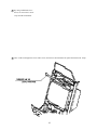
14 -1 REMOVING THE GAME BOARD
1 Turn main switch off.
2 Disconnect all of the Connectors connected to the Filter Board at the front of the Shield Case, 3 connectors on the
left hand side facing the Shield Case and the right-hand side Connector.
3 Take out the thumbscrew securing the Base, and remove the Base from the cabinet with the Shield Case as is
mounted. When removing the Base first withdraw the Base towards you up to the notch portions allowing for
evading the fitting which secures the Base. From that position, lift up and remove the Base. At this time, be very
careful so as not to damage wiring.
4 Take out the 4 screws and remove the Shield Case.
44
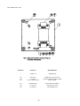
14 - 3 COMPOSITION OF GAME BOARD
Ensure that the DIP SW setting is performed as designated as designated. Failure
to observe this may cause functioning not suitable for the operation, or malfunctioning.
ASSY CASE NAO USA (840-0021D-01) :USA
DIP SW SETTING
IN the product, set all of the DIP SWes to OFF.
45
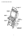
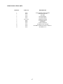
15. DESIGN RELATED PARTS
46
DESIGN RELATED PARTS
ITEM NO.
PART NO.
DESCRIPTION
1
2
3
4
5
6
7
8
9
10
13
14
XXX
XXX
XXX
XXX
XXX
NOA-1507
XXX
XXX
XXX
XXX
XXX
XXX
PLAY INSTRUCTION SH NBA
SUB INSTR SH NBA
POP NBA
STICKER SIDE L
STICKER SIDE R
EMBLEM NAOMI
STICKER FRONT
STICKER F
SHEET EMBLEM
GUARD PLATE CENTER
STICKER CONTROL PANEL OVERLAY
STICKER ??????
47
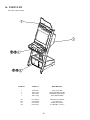
16. PARTS LIST
TOP ASSY VIRTUA NBA
ITEM NO.
PART NO.
DESCRIPTION
1
2
3
7
NOE-1000
NOA-2000
NOA-0001
NOA-1300
ASSY U/R CABI
ASSYCONTROL PANEL
WOODEN BASE MAIN
ASSY BILLBOARD
201
202
203
204
031-0S0416
050-F00400
032-000425
068-441616
CRG BLT STN M4X16
FLG NUT M4
WING BLT M4X25
FLT WSHR 4.4-16X1.6
48
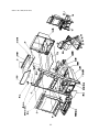
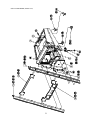
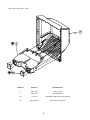
ASSY U/R CABI (NOE-1000)
49
ASSY U/R CABI (NOE-1000)
ITEM NO.
PART NO.
DESCRIPTION
1
2
3
4
5
6
7
8
9
10
11
12
13
14
15
16
17
18
19
20
21
23
24
25
26
27
29
30
NOB-1100
NOA-1200
NOA-1300
NOA-1400
NOA-1500
NOA-4000
NOA-1750
NOA-1801
NOB-1001
NOB-1002
NOA-1003
NOA-1004
NOA-1005
HOT-1007
280-5112
280-5113
280-5114
CTA-1006
CTA-1150
NOC-1700
LOCAL PURCHASE
NOA-1009
NOA-1010
NOA-1011
NOA-1116
NOA-4100
NOA-1014
NOE-1480
ASSY FRAMEWORK UR
ASSY CRT COVER
ASSY BILLBOARD
ASSY CONTROL BOX W/CC
ASSY FRONT PANEL
ASSY ELEC
ASSY SERVICE DOOR
REAR HATCH
FRAME COVER U/R R
FRAME COVER U/R L
ENDCAP R
ENDCAP L
REAR COVER UPPER
LID COIN CNTR
BUSH FOR TV
COLLAR FOR TV
SPACER 6.4-25X2
SCR CAP
ASSY CC BOX WW
AC UNIT UL
FL HOLDER
WSHR PLATE
BILLBOARD HOLDER
FL BRKT
LID COMMUNI PORT
ASSY XFMR
CUCHION SPONGE 580
COIN SELECTOR UNIT
101
102
110
200-5787
LOCAL PURCHASE
601-6231-01
ASSY CLR DSPL 29TYPE 31K 100V
ASSY FL 20W W/CONN HIGH
EDGING NEW TYPE
201
202
203
204
205
206
207
208
209
210
211
212
213
214
215
216
217
218
219
008-T00625-0C
030-000620-S
010-P00408-F
008-T00412-0C
008-T00412-0C
050-F00600
000-P00430-W
000-P00320
032-000425
068-441616
008-B00820-0C
031-000626-0C
060-F00800
000-P00412-W
008-B00620-0B
060-F00500
060-S00500
050-H00500
000-P00308-W
TMP PRF SCR TH CRM M6X25
HEX BLT W/S M6X20
S-TITE SCR PH W/F M4X8
TMP PRF SCR TH CRM M4X12
TMP PRF SCR TH CRM M4X12
FLG NUT M6
M SCR PH W/FS M4X30
M SCR PH M3X20
WING BLT M4X25
FLT WSHR 4.4-16X1.6
TMP PRF SCR BH CRM M8X20
CRG BLT CRM M6X20
FLT WSHR M8
M SCR PH W/FS M4X12
TMP PRF SCR BH BLK M6X20
FLT WSHR M5
SPR WSHR M5
HEX NUT M5
M SCR PH W/FS M3X8
50
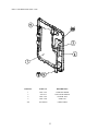
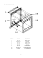
ASSY FRAMEWORK (NOB0-1100)
51
ASSY FRAMEWORK (NOB0-1100)
ITEM NO.
PART NO.
DESCRIPTION
1
2
3
4
5
6
7
8
9
11
NOA-1601
NOB-1101
NOB-1102
NOA-1111X
NOA-1112X
NOA-1113
NOA-1114
HOT-1200
253-5366
NOA-1115
BASE BOX
MAIN FRAME UR R
MAIN FRAME UR L
LOWER BEAM
UPPER BEAM
HOOF R
HOOF L
ASSY CASH BOX DOOR
CASH BOX
TNG REAR HATCH
102
103
104
105
601-5699X
601-10461
601-10462
220-5575
LEG ADJUSTER BOLT M16X75
CASTER D51H66 FREE
CASTER D51H73 FIX
CAM LOCK MASTER W/O KEY
201
202
203
204
205
206
207
050-F00600
030-000620-S
068-652016
050-F00400
010-P00408-F
000-F00310
050-HO1600
FLG NUT 6
HEX BLT W/S M6X20
FLT WSHR 6.5-20X1.6
FLG NUT M4
S-TITE SCR PH W/F M4X8
M SCR FH M3X10
HEXNUT M16
52
ASSY CASH BOX DOOR (HOT-1200)
ITEM NO.
PART NO.
DESCRIPTION
1
3
4
5
HOT-1201
220-5574
HOT-1203
HOT-1204
CASH BOX DOOR
CAM LOCK W/KEYS
CENTER TNG
SIDE TNG
202
065-E00300
E RING 3MM
53
ASSY CC BOX WW (CTA-1150)
ITEM NO.
PART NO.
DESCRIPTION
1
2
3
4
CTA-1151
DP-1167
CTA-1153
CTA-1160
CC BOX WW
TNG LKG
CHUTE W
SW UNIT
101
102
97-1003-05
220-5575
ASSY C.C.CHUTE DOOR
CAM LOCK MASTER W/O KEY
54
ASSY SW UNIT (CTA-1160)
ITEM NO.
PART NO.
DESCRIPTION
1
CTA-1161
SW BRKT
101
102
104
220-5179
601-0042
509-5028
VOL CONT B-5K OHM
KNOB 22MM
SW PB 1M
55
ASSY CRT COVER (NOA-1200)
ITEM NO.
PART NO.
DESCRIPTION
1
2
NOA-1201
NOA-1202
CRT COVER
SPEAKER BOX
101
130-5205
SPEAKER 4OHM 10W 100 W/SHIELD
201
000-P00410-W
M SCR PH W/FS M4X10
56
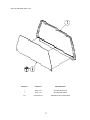
ASSY BILLBOARD (NOA-1300)
ITEM NO.
PART NO.
DESCRIPTION
1
2
NOA-1301
NOA-1302
BILLBOARD PLATE
BILLBOARD SHEET
201
008-t00408-0C
TMP PRF SCR TH CRM M4X8
57
ASSY FRONT PANEL (CTA-1400)
ITEM NO.
PART NO.
DESCRIPTION
1
2
3
4
5
6
7
NOA-1501
NOA-1502-01
NOA-1503
NOA-1504
NOA-1505
NOA-1506
NOA-1507
FRONT PANEL
MASK MS9
LIGHT COVER
PRISM PLATE
LID GCS
LID VMS
EMBLEM NAOMI
201
202
000-P00416-W
012-P00416
M SCR PH W/FS M4X12
TAP SCR #2 PH 4X16
58
ASSY AC UNIT (NOC-1700)
ITEM NO.
PART NO.
DESCRIPTION
1
NOB-1701
AC BRKT
101
102
103
509-5876
214-0202
512-5046-5000
LOCKER SW JW-L21RKK
AC INLET PANEL TYPE
C.P. 5000MA CE UL
201
202
203
204
000-P00308-W
050-H00400
060-F00400
060-S00400
M SCR PH W/FS M3X8
HEX NUT M4
FLT WSHR M4
SPR WSHR M4
59
ASSY CONTROL BOX ( )
60
61
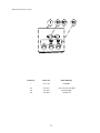
ASSY CONTROL PANEL (NOA- 20001)
ITEM NO.
PART NO.
DESCRIPTION
1
2
NOA-2002
NOA-2003
CTRL PNL BASE 2A6B
CTRL PNL PLATE 2A6B
101
102
103
610-6723-4C01
509-5756-01
509-5755-01
ASSY ANALOG JOY 4C GREEN
SW PB D24 YELLOW
SW PB D30 GREEN
201
202
203
204
050-U00400
060-F00400
060-S00400
050-H00400
U NUT M4
FLT WSHR M4
SPR WSHR M4
HEX NUT M4
62
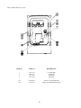
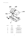
ASSY ELEC (NOA-4000)
ITEM NO.
PART NO.
DESCRIPTION
1
NOA-4001
ELEC BASE
101
102
103
104
105
108
400-5397
560-5407-UL
838-13616
838-11856-UL
509-5876
601-6231-B60
SW REGU FOR JVS
AUDIO XFMR 120V 17V2.1AX2
AUDIO POWER AMP 2 CH
CONNECT BD UL
LOCKER SW JW-L21RKK
EDGING NEW TYPE L=60
201
202
203
010-P00406-F
010-P00306-F
010-P00320-F
S-TITE SCR PH W/F M4X6
S-TITE SCR PH W/F M3X6
S-TITE SCR PH W/F M3X20
63
ASSY MAIN BD (CTA-4100)
ITEM NO.
PART NO.
DESCRIPTION
1
2
NOA-4101
840-0021D-01
WOODEN BASE MAIN
ASSY CASE NAO NBA USA
101
102
103
838-13616
838-13739
560-5413-V
AUDIO POWER AMP 2CH
SW BD NAOMICABINET
XFMR 100V 12.8V6.3A
201
000-P00408-W
M SCR PH W/FS M4X8
64
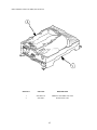
ASSY SHIELD CASE NAO NBA (840-0021D-01)
ITEM NO.
PART NO.
DESCRIPTION
1
2
840-0021A-01
840-0021C
SHIELD CASE NBA NAO USA
ROM CASE NAO
65
ASSY XFMR (NOA-4100)
ITEM NO.
PART NO.
DESCRIPTION
1
NOB-4101
XFMR BASE
101
102
103
560-5426-V
514-5093
LOCAL PURCHASE
XFMR 100-120V 100V5.5A
FUSE HOLDER F-64AB COVER
FUSE 5000MA
201
202
203
000-P00416-W
011-T03512
011-P00312
M SCR PH W/FS M4X16
TAP SCR TH 3.5X12
TAP SCR PH 3X12
66
VISIT OUR SERVICE WEBSITE!